

Page 1
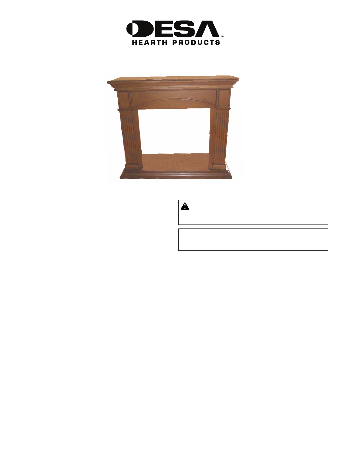
W32RO MANTEL AND BASE
ASSEMBLY AND INSTALLATION INSTRUCTIONS
IMPORTANT: Read entire instruction sheet before
assembling or installing mantel kit.
This mantel is only approved for use with DESA
Heating, LLC 32" replace systems. Do not use
mantel with any other product.
This mantel kit contains the following:
• Mantel pieces - unassembled and marked as follows:
#1 Base
#2 Right Side with arrow
#3 Right Front Leg with arrow
#4 Left Side with arrow
#5 Left Front Leg with arrow
#6 Header with arrow
#7 Top
• Hardware Kit*
14 - Metal Brackets 118937-01
28 - Screws M6 x 12 mm (1/2") 121149-01
11 - Screws M6 x 30 mm (1 1/4") 121335-01
11 - Washers M6 121336-01
1 - Allen Wrench 121337-01
* Extra hardware may be included.
If any wood pieces are missing or damaged, contact the
dealer where you purchased this mantel for replacement.
If hardware is missing or damaged, contact DESA Heating,
LLC at 1-866-672-6040 for referral. You can also visit DESA
Heating, LLC's web site at www.desatech.com.
Note: Gather all mantel pieces together before assembling.
ASSEMBLING MANTEL
WARNING: Use only 1/2" screws to attach metal
angle brackets. Damage to mantel will result if other
screws are used for this purpose.
IMPORTANT: More than one person is required to lift
assembled mantel. Lift mantel by leg assemblies. Lifting
by header or mantel top could damage mantel.
When assembling mantel do not tighten screws completely
until told to do so. There should be some play in the pieces
to allow for proper alignment and best possible t. It is very
important that more than one person assemble mantel. Panels
must be held in proper alignment to each other while tightening screws to assure fewer gaps and proper surface align-
ment. When tightening screws, do not over tighten. This may
cause threads to strip. The supplied Allen wrench should be
used rather than a power screwdriver. Panels have threaded
inserts installed at screw locations. Screws should start and
turn easily in threaded holes when assembled according to
instructions. Do not force screws into holes.
IMPORTANT: A serial number label is located inside of right
side panel and on outside package. When calling to request
technical assistance or for replacement parts please have
serial number ready.
www.desatech.com
Page 2
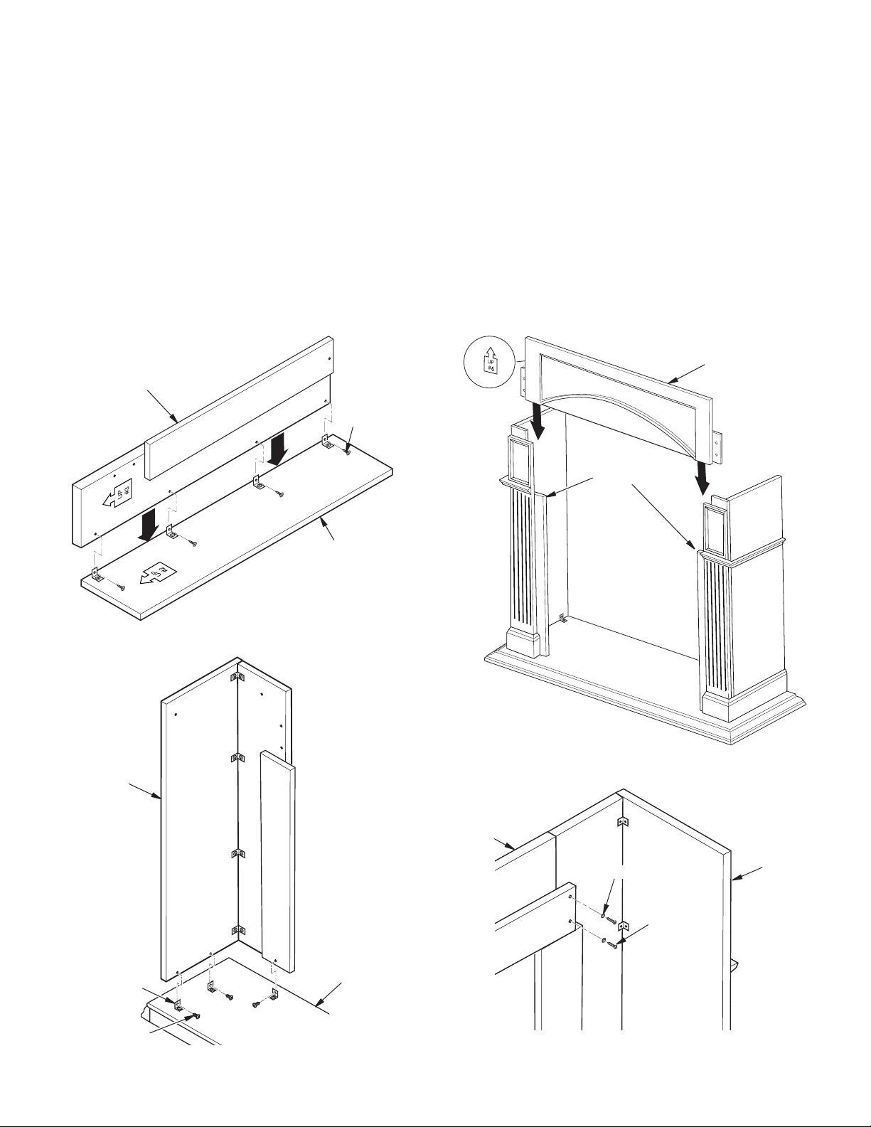
1. Lay right side panel (#2) face down on a soft surface
to avoid marking nish. Attach four brackets with 1/2"
screws to bottom of right front leg (#3) leaving screws
slightly loose. Face brackets out (see Figure 1). Place
right front leg (#3) over right side (#2) as shown in Figure
2, paying close attention to direction arrow pointing up
on panels. Align threaded holes with brackets on side.
Start four 1/2" screws through brackets. Align bottom of
side and leg assembly so they are ush with each other.
Hold these pieces securely in alignment while tightening
(but not over tightening) screws.
2. Assemble left side (#4) and left leg (#5) as described in
step 1.
3. Attach 6 brackets to base (#1) at threaded hole locations
using 1/2" screws leaving screws loose. Face brackets
toward outside (see Figure 2).
Right Front Leg
1/2" Screws
4. Place right side/leg assembly on base and align threaded
holes with brackets. Start 1/2" screws through brackets
into threaded holes in side/leg assembly. Back of side/
leg assembly should be ush with back of base. Assure
alignment is correct and spaces are at a minimum and
tighten leaving screws slightly loose.
5. Assemble left side/leg assembly to base (#1) following
step #4.
HEADER ASSEMBLY
Position header (#6) between leg assemblies onto shoulders with direction arrow pointing up. Align threaded holes
in header with holes in leg assembly (see Figure 4). Attach
header (#4) with four 1 1⁄4" screws and washers (see Figure
4). Hold header in proper alignment with leg assemblies and
tighten, leaving screws slightly loose.
Header
Right
Side/Leg
Assembly
Figure 1 - Attaching Front Leg
Right Side
Left Leg
Assembly
Header
Shoulder
Right Leg
Assembly
Figure 3 - Installing Header
Washer
Leg
Assembly
2
Bracket
1/2" Screw
Figure 2 - Leg Assembly to Base
Base (#1)
www.desatech.com
1 1/4" Screw
Figure 4 - Attaching Header to Leg Assembly
122075-01B
Page 3

MANTEL TOP ASSEMBLY
Place mantel top (#7) on mantel assembly. Align back of top
with back of sides. Using four 1 1/4" screws with washers, place
two in each mantel side assembly (see Figure 5). With three
1 1/4" screws with washers, attach top to header. Make sure
all pieces are aligned properly and tighten, leaving screws
slightly loose.
Washer
11/4" Screw
Top (#7)
Back of Top
Flush with
Back of Leg
Assembly
Leg
Assemblies
Figure 5 - Attaching Top to Leg and Header Assembly
Figure 6 - Installing Fireplace
GAS FIREPLACE INSTALLATION
1. Fireplace should be fully assembled. See Assembling
Fireplace in replace owner’s manual.
2. Place mantel base close to installation location. See replace owner’s manual for installation clearances. Leave
enough room to insert replace from back of mantel.
3. Install gas line. See Connecting to Gas Supply in replace
owner’s manual. Remember to leave access to the gas
shutoff valve somewhere on the base or where it is ac-
cessible to the user.
4. Check for leaks. See Checking Gas Connections in re-
place owner’s manual.
5. Position replace inside mantel (see Figure 6). Carefully
position gas lines. Important: Use caution when positioning replace on base. Base may scratch easily. Make
sure replace is in proper position within mantel opening
before continuing with installation.
6. Fireplace with louver door: Lower bottom louver door.
Use two screws provided in hardware package and attach
replace to wooden base. Close louver door.
Fireplace with xed louver: Before installing logs or
burner assembly (see owner’s manual) remove screws
securing oor to assembly. Lift oor for access to bottom of replace. Use two screws provided in replace
hardware package and attach replace base to wooden
base. Reinstall oor with screws removed previously.
7. Carefully push mantel and base into position against
wall.
ELECTRIC FIREPLACE INSTALLATION
This mantel can be used with DESA Heating, LLC's 32" Electric
Fireplace. Electric replaces install from the front of mantel.
To install electric replace see replace instruction manual.
Use caution when positioning replace on base. Base may
scratch easily.
122075-01B
www.desatech.com
3
Page 4

122075 01
DESA Heating, LLC
2701 Industrial Drive
P.O. Box 90004
Bowling Green, KY 42102-9004
www.desatech.com
1-866-672-6040
NOT A UPC
122075-01
Rev. B
10/08
 Loading...