

Desa VP2600T, VP1600A, VP1600TA, VP2600A, VP2600TA Service Manual
...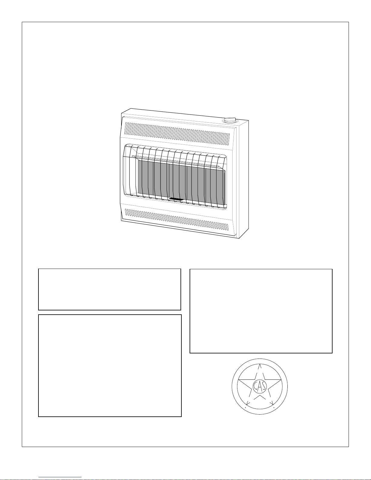
SERVICE MANUAL
VENT-FREE GAS HEATERS
VANGUARD FRONT
CERAMIC PLAQUE MODELS
FOR YOUR SAFETY
Do not store or use gasoline or other
flammable vapors and liquids in the
vicinity of this or any other appliance.
FOR YOUR SAFETY
WHAT TO DO IF YOU SMELL GAS
• Do not try to light any appliance.
• Do not touch any electrical switch; do
not use any phone in your building.
• Immediately call your gas supplier
from a neighbor’s phone. Follow the
gas supplier’s instructions.
• If you cannot reach your gas supplier,
call the fire department.
GRH/PV 005
WARNING: Improper installation, ad-
justment, alteration, service or maintenance can cause injury or property damage. Refer to this manual for correct
installation and operational procedures.
For assistance or additional information
consult a qualified installer, service
agency or the gas supplier.
T
I
O
A
N
N
A
H
T
I
W
S
E
I
A
L
P
M
O
C
N
G
A
I
S
S
E
S
D
C
L
S
A
R
E
M
O
C
E
R
T
F
I
C
E
A
N
T
Y
S
T
A
N
D
A
R
D
N
S
O
I
T
I
A
D
E
I
F
I
G 009
Save this manual for future reference.

VENT-FREE GAS HEATER SERVICE MANUAL
TABLE
OF
CONTENTS
Section 1 - Safety Information
Safety Requirements ..............................................................................................3
Warnings................................................................................................................. 3
Section 2 - Introduction
Technical Service Department ............................................................................... 4
Product Features .................................................................................................... 4
Accessories ............................................................................................................ 4
Section 3 - General Operation and Component Descriptions
General Operation .................................................................................................. 5
Burner Assembly .................................................................................................... 5
Ignition System ....................................................................................................... 5
Control Valve .......................................................................................................... 6
Gas Regulator ........................................................................................................ 6
Oxygen Depletion System ...................................................................................... 6
Section 4 - Tools and Equipment ................................................................................. 7
Section 5 - Installation
Gas Type ................................................................................................................ 8
Location: Safety Precautions .................................................................................. 8
Gas Supply Installation ........................................................................................... 9
Propane Installation ................................................................................................ 10
External Regulators ................................................................................................ 10
Section 6 - Test Procedures
Testing Gas Supply Line Connections ................................................................... 11
Testing Heater Gas Connections ........................................................................... 11
Correcting Leaks .................................................................................................... 11
Testing Control Valve and Thermocouple .............................................................. 12
Section 7 - Specifications............................................................................................. 13
Section 8 - Troubleshooting
Ignition Problems
No Spark................................................................................................................. 14
Ignitor Sparks, But Pilot Will Not Light .................................................................... 15
Pilot Lights, But Will Not Stay Lit ............................................................................ 16,17
Main Burner Does Not Light (pilot stays lit) ........................................................... 18
Delayed Ignition Of Main Burner ............................................................................ 18
Combustion Problems
Backfiring During Operation ................................................................................... 19
Smoke or Unwanted Odors .................................................................................... 19
Gas Odor ................................................................................................................ 19
Service Information ...................................................................................................... Back Page
2
VENT-FREE GAS HEATER SERVICE MANUAL
SECTION
1
SAFETY INFORMATION
Safety Requirements
This service manual is intended for use by
individuals with adequate electrical and mechanical skills. Attempts to repair this heater by
WARNINGS
IMPORTANT: Read the Owner’s Manual carefully and completely before trying to assemble,
operate, or service this heater. Improper use of this heater can cause serious injury or death from
fire, explosion, electrical shock, electrocution, and carbon monoxide poisoning.
!
WARNING ICON G 001
!
DANGER
WARNING ICON G 001
Carbon monoxide poisoning may lead to death!
Early signs of carbon monoxide poisoning resemble the flu, with headaches, dizziness, and/or
nausea. If you have these signs, the heater may not be working properly. Get fresh air at once!
Have heater serviced. Some people such as pregnant women, persons with heart or lung disease,
persons with anemia, those under the influence of alcohol, and those at high altitudes are more
affected by carbon monoxide than others. Make certain you read and understand all Warnings.
Keep the Owner’s Manual for reference. It is your guide to safe and proper operation of this heater.
1. Use only propane gas for models designated as propane.
2. Use only natural gas for models designated as natural.
3. If using propane model, do not place propane supply tank inside any structure. The
propane supply tank must be located outdoors.
4. If you smell gas
• Shut off gas supply.
• Do not try to light any appliance.
• Do not touch any electrical switch; do not use any phone in your building.
• Immediately call your gas supplier from a neighbor’s phone. Follow the gas supplier’s
instructions.
• If you cannot reach your gas supplier, call the fire department.
5. Never install the heater
• in sleeping quarters, a mobile home, or a recreational vehicle
• where curtains, furniture, clothing, or other flammable objects are less than 36 inches
from the front, top, or sides of the heater
• as a fireplace insert
• in high traffic areas
• in windy or drafty areas
6. Always run heater at LOW, THERMOSTAT/MEDIUM, or HIGH locked positions. Never set
control knob between locked positions. Poor combustion and higher levels of carbon monoxide
may result.
7. Open window to admit fresh, outside air when using heater. Open window one (1) or two (2)
inches. When used without fresh, outside air, heater may give off carbon monoxide gas.
8. Never run heater in small, closed room. Open door into next room to help ventilate.
9. If heater shuts off, do not relight until you provide fresh, outside air. If heater keeps shutting
off, have it serviced.
10. Do not run heater
• where flammable liquids or vapors are used or stored
• under dusty conditions
11. Never place any objects on the heater.
12. Surface of heater becomes very hot when running heater. Keep children and adults away
from hot surface. Heater will remain hot for a time after shutdown. Allow surface to cool
before touching.
13. Make sure grill guard is in place before running heater.
14. Do not alter heater or its controls. Any change may create a safety hazard.
15. Make sure heater is turned off, unplugged, and cool before servicing.
individuals without those skills can result in
personal injury as well as property damage.
3
VENT-FREE GAS HEATER SERVICE MANUAL
SECTION
2
INTRODUCTION
Technical Service Department
The Technical Service Department, located in
Bowling Green, Kentucky, is committed to assisting our Authorized Service Centers and Dealers to provide prompt, efficient service. If you
need assistance or have questions about servicing problems, please call DESA International’s
Technical Service Department at 1-800-323-
5190.
Product Features
The ceramic plaque heaters covered by this
service manual have many features that assure
customer satisfaction and comfort.
•
Infra-red Heat:
plaques give off infra-red radiant light which
travels through the air and heats nearby
objects.
•
Variable Heat Output:
heaters can be adjusted to one of three
alternative heat settings to provide user
comfort. The thermostat heaters can be
adjusted to the desired heat setting to permit economical use. In the event of a power
The glowing ceramic burner
The non-thermostat
NOTE: This number is ONLY for technical service assistance and CANNOT be used for ordering parts, billing questions, order status, etc. For
sales department and parts ordering, call 1-502781-9600.
outage, the heater can be operated manually on high or low.
Piezo Electric Ignition:
•
started and operated without matches or
other external means. The pilot is ignited by
a spark created from the piezo ignitor when
the control knob is depressed and turned to
the “PILOT” position.
•
Oxygen Depletion System:
designed to shut off if the oxygen level in
the room falls to an unacceptable level.
The heater can be
The heater is
Accessories
The following accessories are available from
DESA International:
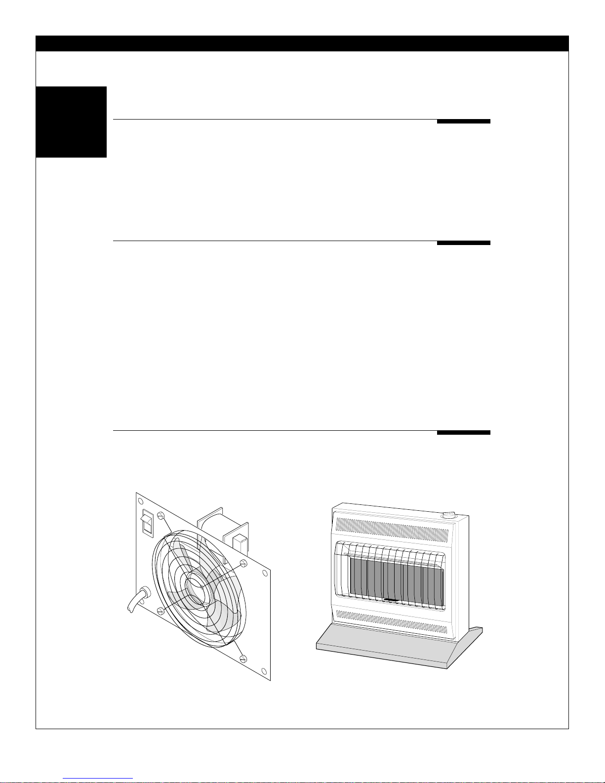
1. Fan Kit GA2100A. The fan accessory pro-
vides better heat distribution in the room.
A 007FAN ACCESSORY-GRH
Figure 1. Optional Fan Kit
2. Floor Mounting Stand GA4000 (3-plaque
models) and GA4010 (5-plaque models).
The floor stand allows the heater to be
installed away from a wall.
OPTIONAL FLOOR MOUNT-GRH
Figure 2. Optional Floor Mounting Stand
A 005
For accessories, contact authorized dealers of this product. If they are unable to supply
accessory parts, call DESA International at 1-502-781-9600.
4
VENT-FREE GAS HEATER SERVICE MANUAL
SECTION
3
GENERAL OPERATION AND COMPONENT DESCRIPTIONS
General Operation
NOTE: See Owner’s Manual for operating
procedure.
The heater is operated by the control knob
located on the top of the heater. Be sure that the
service supply valve is open and that the manual
shut-off valve (Figure 8, page 9) is fully open.
Depressing the control knob and turning it to the
“PILOT” position will direct gas to the pilot and
provide a spark to light the pilot. The control
knob must be held down (at least 10 seconds)
until the thermocouple is heated enough to hold
the valve open. Once the pilot flame is
established, the control knob can be released
and turned to any of the operating position
settings. The control knob can also be left in the
Burner Assembly
The burner assembly is constructed of a plated
steel burner case with ceramic plaques cemented into the face. A metal frame assures
uniform spacing between the plaques. The gas
orifices are mounted at the bottom of the air/gas
inlet tubes. The air/gas mixture is distributed to
“PILOT” position so that the heater is ready to
use.
Turning the control knob operates the control
valve and directs the flow of gas to the pilot and
the burner plaques. The gas is mixed with air
and is injected into the burner chambers through
tubes in the bottom of the burner. The air/gas
mixture burns on the surface of the ceramic
burner plaques, causing the ceramic plaques to
glow with a radiant orange color. With proper
care and servicing, the heater should give many
years of satisfactory use to the customer. Be
sure to inspect and service the heater at least
annually.
the plaques through the steel burner chambers
and through the small holes in the ceramic
plaques. The air/gas mixture burns near the
surface of the ceramic plaques, resulting in the
production of both radiant and convected heat.
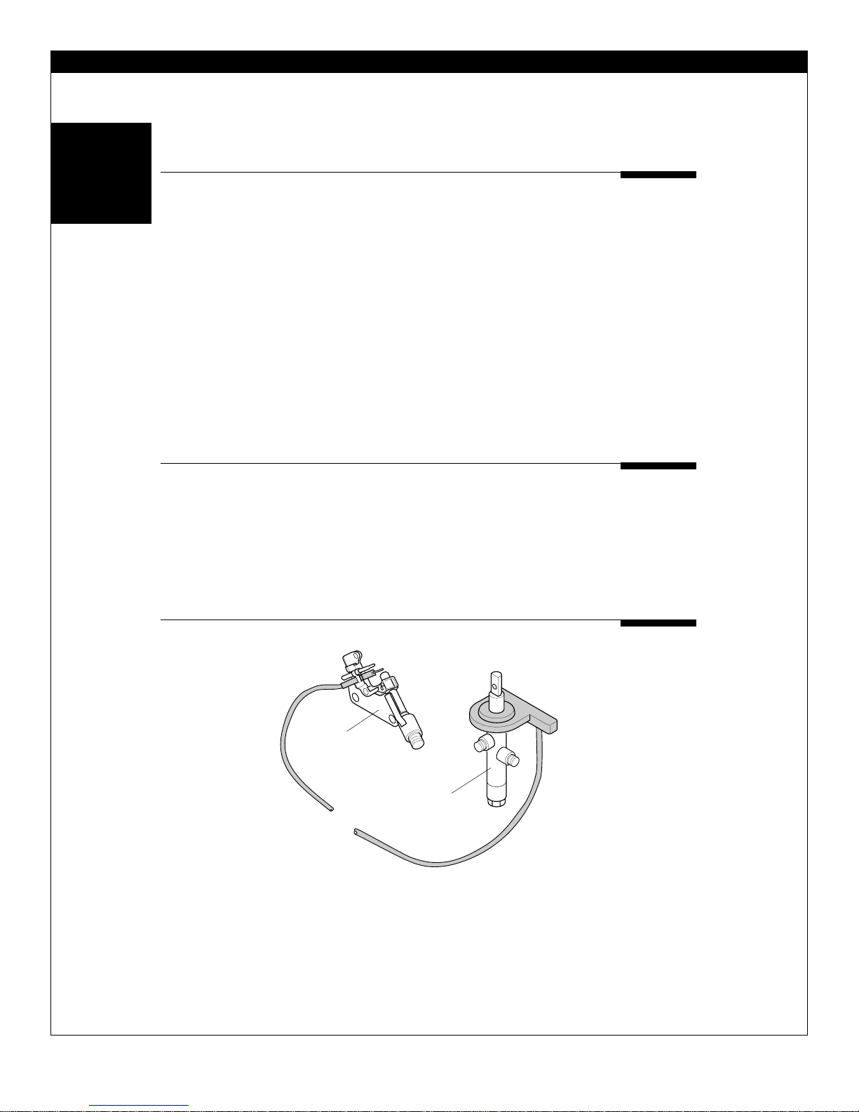
Ignition System
The ignitor assembly utilizes a piezo electric
ignition system. The spark generator is built into the control valve and will provide a spark to the pilot when the control
knob is fully depressed and turned
Pilot
Control
Valve
IGNITION SYSTEM
Figure 3. Ignition System
from the “OFF” position to the “PILOT” position.
The resulting high voltage spark ignites the gas
at the pilot tube. The pilot flame will
in turn light the main burners
when the control knob is
rotated to the desired
heat setting.
GRH/P027
5
VENT-FREE GAS HEATER SERVICE MANUAL
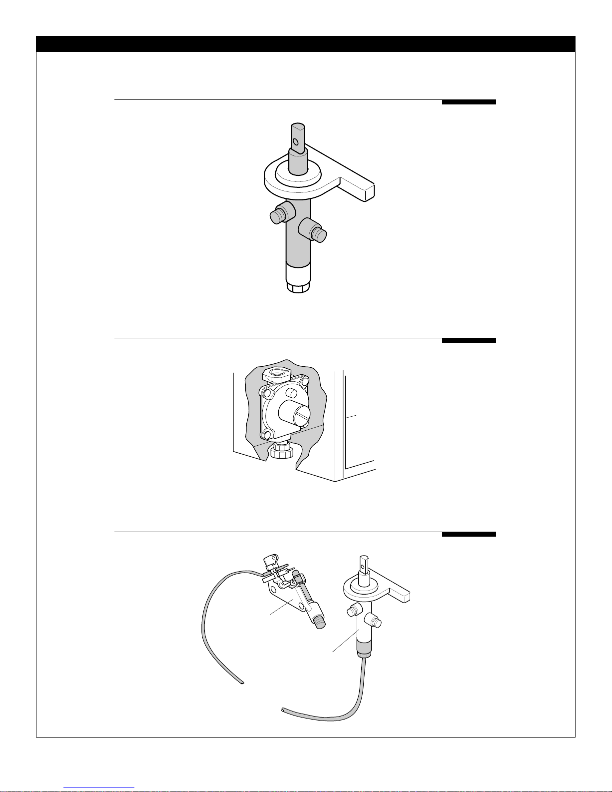
Control Valve
The control valve directs the flow of gas to the
pilot burner and the main burners. The control knob should be slightly depressed and
rotated to select the appropriate heat setting, the “PILOT” setting or to turn the
heater off.
The control valve will maintain gas
flow to the main burner and the pilot
burner only if the thermocouple which
is mounted on the pilot burner is sufficiently heated. The heated thermo-
Figure 4. Control Valve
Gas Regulator
The gas regulator is used to reduce the incoming
gas pressure to the appropriate pressure for proper operation of the heater. The
regulator pressure is preset
and cannot be adjusted.
couple provides a low level electric current to an
electromagnetic plunger in the control valve.
This low level electric current keeps the
plunger open allowing gas to flow to the
pilot and the main burner. If the pilot
flame is extinguished, or if the
pilot flame lifts off of the
thermocouple due to lack of
oxygen, the electric current to
the valve will be reduced and the plunger will
close, shutting off all gas flow to the heater.
Gas Valve
GRH/P028
NOTE: Propane heaters also require an exter-
nal regulator (11"-14" W.C.) be installed. The external regulator is not
supplied with the heater.
Oxygen Depletion System (O.D.S.)
The pilot burner is designed to produce a precision flame which will lift off of the pilot
thermocouple if the oxygen content of the surrounding air is too low.
The resulting cooling
of the pilot thermo-
6
Figure 5. Gas Regulator
GAS REGULATOR GRH/P 032
couple will cause the control valve to close,
Pilot
Control
Valve
O.D.S.
GRH/P 029
Figure 6. Oxygen Depletion System
shutting off all gas flow to the
heater. The oxygen deple-
tion system is required
on all models of ventfree heaters covered
by this manual.
 Loading...