

Desa VMH1OTPB, EFS1OTN, VMH26PRA, VMH26NRA, EFS26PR Owner's Operation And Installation Manual
...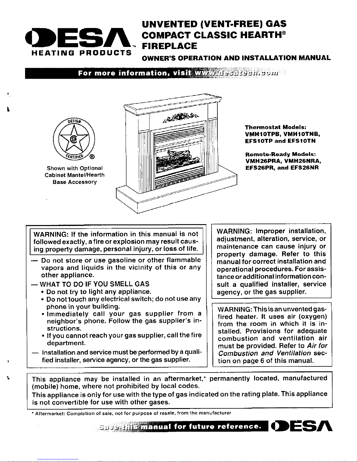
UNVENTED (VENT-FREE) GAS
MESA
COMPACT CLASSIC HEARTH®
TM
FIREPLACE
HEATING PRODUCTS
OWNER'S OPERATION AND INSTALLATION MANUAL
For more information, visit
Thermostat Models:
VMH1OTPB, VMH1OTNB,
EFS1OTP and EFS1OTN
Remote-Ready Models:
VMH26PRA, VMH26NRA,
EFS26PR, and EFS26NR
Shown with Optional
Cabinet Mantel/Hearth
Base Accessory
WARNING: If the information in this manual is not
followed exactly, a fire or explosion may result caus-
ing property damage, personal injury, or loss of life.
—
Do not store or use gasoline or other flammable
vapors and liquids in the vicinity of this or any
other appliance.
— WHAT TO DO IF YOU SMELL GAS
•
Do not try to light any appliance.
•
Do not touch any electrical switch; do not use any
phone in your building.
•
Immediately call your gas supplier from a
neighbor's phone. Follow the gas supplier's in-
structions.
•
If you cannot reach your gas supplier, call the fire
department.
—
Installation and service must be performed by a quali-
fied installer, service agency, or the gas supplier.
WARNING: Improper installation,
adjustment, alteration, service, or
maintenance can cause injury or
property damage. Refer to this
manual for correct installation and
operational procedures. For assis-
tance or additional information con-
sult a qualified installer, service
agency, or the gas supplier.
WARNING: This is an unvented gas-
fired heater. It uses air (oxygen)
from the room in which it is in-
stalled. Provisions for adequate
combustion and ventilation air
must be provided. Refer to
Air for
Combustion and Ventilation
sec-
tion on page 6 of this manual.
This appliance may be installed in an aftermarket,* permanently located, manufactured
(mobile) home, where not prohibited by local codes.
This appliance is only for use with the type of gas indicated on the rating plate. This appliance
is not convertible for use with other gases.
Aftermarket: Completion of sale, not for purpose of resale, from the manufacturer
-
.jk
iivaI for future reference.
aliEsft
TABLE OF CONTENTS
SAFETY INFORMATION
TABLE OF CONTENTS
SAFETY INFORMATION
2
CLEANING AND MAINTENANCE
29
PRODUCT IDENTIFICATION
3
WIRING DIAGRAM
29
OPTIONAL REMOTE CONTROL ACCESSORIES
4
TROUBLESHOOTING
30
LOCAL CODES
4
SPECIFICATIONS
33
PRODUCT FEATURES
4
REPLACEMENT PARTS
33
UNPACKING
4
SERVICR HINTS
33
ASSEMBLY
5
TEC. -0-IICAL SERVICE
33
AIR FOR COMBUSTION AND VENTILATION
6
ILLUS :RATED PARTS BREAKDOWN AND PARTS LIST
34
INSTALLATION
8
ACCESSORIES
38
OPERATING FIREPLACE
23
OWNER'S REGISTRATION FORM
41
INSPECTING BURNERS
28
WARRANTY INFORMATION
Back Cover
SAFETY INFORMATION
A
WARNINGS
A
WARNING: This product contains and/or generates
A
WARNING: Do not use a blower insert, heat
chemicals known to the State of California to cause
exchanger insert, or other accessory not approved
cancer or birth defects, or other reproductive harm.
for use with this fireplace.
IMPORTANT: Read this owner's manual carefully and
A
WARNING: Do not allow fans to blow directly into
completely before trying to assemble, operate, or ser-
the fireplace. Avoid any drafts that alter burner flame
vice this fireplace. Improper use of this fireplace can patterns. Ceilihs fans can
create
drafts that alter
cause serious injury or death from burns, fire, explo-
burner flame patterns. Altered burner patterns can
sion, electrical shock, and carbon monoxide poisoning.
cause sooting.
Due to high temperatures, the appliance should be
A
DANGER: Carbon monoxide poisoning may lead
located out of traffic and away from furniture and
to death!
draperies.
•
Carbon Monoxide Poisoning: Early signs of carbon monoxide
poisoning resemble the flu, with headaches, dizziness. or nausea.
If you have these signs, the fireplace may not he working properly.
Get fresh air at once! Have fireplace serviced. Some people
are
more affected by carbon monoxide than others. These include
pregnant women, people with heart or lung disease
OF
after
those under the influence of alcohol and those at high altitudes.
Natural and Propane/LP Gas: Natural and propanc/LT gases are
odorless. An odor-making agent is added to the gas. The odor
helps you detect a gas leak. However, the odor added to the gas can
fade. Gas may be present even though no odor exists.
Make certain you read and understand all warnings. Keep this
manual for reference. It is your guide to safe and proper operation
of this fireplace.
Do not place clothing or other fiammablematerial on
or near the appliance. Never place any objects on
the heater.
Fireplace front and screen become very hot when
running heater. Keep children and adults away
from
hot surfaces to avoid burns or clothing ignition.
Fireplace will remain hot for a time after shutdown.
Allow surfaces to cool before touching.
Carefully supervise young children when they are in
the room with fireplace. When using the hand-held
remote accessory (Remote-Ready Models Only), keep
selector
switch in the
OFF position to
prevent chil-
dren
from turning on burners with remote.
—
You must operate this fireplace with the fireplace
A
WARNING: Any change to this fireplace or its
controls can be dangerous.
screen in place. Make sure fireplace screen is closed
before running fireplace.
L
--
For
more informatiofl
j
J.1
d
z.J
).S.111_1
107072 el)
SAFETY INFORMATION
PRODUCT IDENTIFICATION
SAFETY INFORMATION
Continued
Keep the appliance area clear and free from combus-
tible materials, gasoline, and other flammable vapors
and liquids.
I. This appliance is only for use with the type of gas indicated on
the rating plate. This appliance is not convertible for use with
other gases.
2.
Do not place propane/LP supply tank(s) inside any structure.
Locate propane/LP supply tank(s) outdoors.
3.
If you smell gas
•
shut off gas supply
•
do not try to light any appliance
•
do not touch any electrical switch; do not use any phone in
your building
•
immediately call your gas supplier from a neighbor's phone.
Follow the gas supplier's instructions
•
if you cannot reach your gas supplier, call the lire department
4.
This fireplace shall not be installed in a bathroom. Remote-
Ready Models shall not be installed in a bedroom.
5.
Do not use this fireplace as a wood-buming fireplace. Ilse only
the logs provided with the fireplace.
6.
Do not add extra logs or ornaments such as pine cones, ver-
MICUilte, or rock wool. Using these added items can cause soot-
ing. Do not add lava rock around base. Rock and debris could
fall into the control area of fireplace.
7.
This fireplace is designed to be smokeless. If logs ever appear
to smoke, turn off fireplace and call a qualified service person.
Note: During
initial operation. slight smoking could occur due
to log curing and fireplace burning manufacturing residues.
8.
To prevent the creation of soot, follow the instructions in
Clean-
ing and Maintenance, page
29.
9.
Before using furniture polish, wax, carpet cleaner, or similar
products. turn fireplace off. If heated, the vapors from these
products may create a vs hire powder residue within burner box
or on adjacent" alls or furniture.
10.
This fireplace needs fresh air ventilation to run properly. This
fireplace has an Oxygen Depletion Sensing tODS) safety
shutoff system. The ODS shuts down the fireplace if not enough
fresh air is available. See
Airlar Combustion and Ventilation.
pages 6 through S. If fireplace keeps shutting off, see
Trouble-
shooting,
pages 30 through 32.
It. Do not run fireplace
•
where flammable liquids or vapors are used or stored.
•
under dusty conditions.
2. Do not use this fireplace
IC)
cook food or burn paper or other
objects.
15.
Turn off and unplug fireplace and let cool before servicing. Only
a qualified service person should service and repair fireplace.
16.
Operating fireplace above elevations of 4,500 feet could cause
pilot outage.
17.
Do not operate fireplace if any log is broken. Do not operate
fireplace if a log is chipped (dime-surd or larger).
IS. To prevent pertbrmance problems, do not use propane/LP fuel
tank of less than 100 lbs. capacity.
19. Provide adequate clearances around air openings.
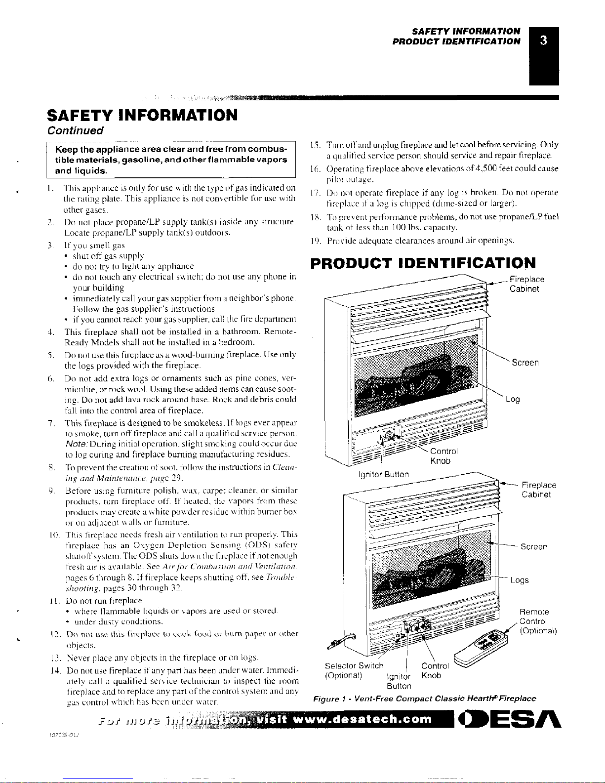
PRODUCT IDENTIFICATION
Fireplace
Cabinet
Screen
og
Ignitor
Button
Fireplace
Cabinet
Screen
Logs
emote
,-,„Th
-------,4_,/
c.---
---
Control
(Optional)
13.
Never place any objects in the fireplace or on logs.
14.
Do not use fireplace if any part has been under water. Immedi-
Selector Switch
Control
al)
ately call a qualified service technician to inspect the room
(Option
Ignitor
Knob
fireplace and to replace any part of the control system and any
Button
gas control which has been under water.
Figure 1 - Vent-Free Compact Classic Hearth° Fireplace
id!'
in!, if _; hi]
piy,14-:,'
,
:lirlisit www•desatech.com
CIDESA
07032-01J
OPTIONAL REMOTE CONTROL ACCESSORIES
LOCAL CODES
PRODUCT FEATURES
UNPACKING
OPTIONAL REMOTE
CONTROL ACCESSORIES
(For Remote-Ready Models Only)
There are four optional remote controls that can be purchased
separately for Remote-Ready Models only:
•
wall switch
• hand-held ON/OFF remote
•
wall thermostat
• hand-held thermostat remote
See
Accessories,
pages 38 and 39.
LOCAL CODES
Install and use fireplace with care. Follow all local codes. In the
absence of local codes, use the latest edition of
The :National Fuel
Gas
Code ANSI Z22$. I/NFPA 54*.
*.Available from:
American National Standards Institute, Inc.
1430 Broadway
New York, NY 10018
National Fire Protection Association, Inc.
Batterymarch Park
Quincy, MA 02269
PRODUCT FEATURES
SAFETY PILOT
This fireplace has a pilot with an Oxygen Depletion Sensing (ODS)
safety shutoff system. The ODS/pilot is a required feature for vent-tree
room fireplaces. The ODS/pilot shuts off the fireplace if there is not
enough fresh air.
PIEZO IGNITION SYSTEM
This fireplace has a piezo ignitor. This system requires no matches,
batteries, or other sources to light fireplace.
THERMOSTATIC HEAT CONTROL FOR
THERMOSTAT-CONTROLLED MODELS
Thermostat-Controlled models have a thermostat sensing bulb and
a control valve. The thermostat will automatically modulate the heat
output to maintain a consistent room temperature. This results in
greater fireplace comfort. This can also result in lower gas hills.
UNPACKING
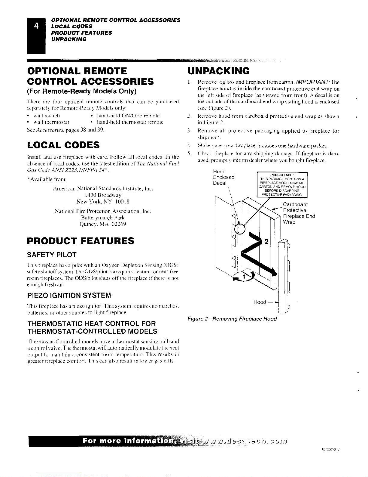
1.
Remove log box and fireplace from carton.
IMPORTANT:The
fireplace hood is inside
the
cardboard protective end wrap on
the left side of fireplace (as viewed from front). A decal is on
the outside of the cardboard end wrap stating hood is enclosed
(see figure
2).
2.
Remove hood from cardboard protective end wrap as shown
in Figure 2.
3.
Remove all protective packaging applied to fireplace for
shipment.
4.
Make sure your fireplace includes one hardware packet.
3. Check tireplace for any shipping damage. If fireplace is dam-
aged, pror I ipt's! inform dealer where you bought fireplace.
Hood
Enclosed
Decal
THS PACKAGE CONTAINS A
FIREPLACE HOOD UNWRAP
CARTON AND RPAAOVE HOOD
BEFORE DISCARDING
PROTECTIVE PACKAGING
Cardboard
Protective
Fireplace End
Wrap
<!
Hood —
Figure 2 - Removing Fireplace Hood
For more lot
1070,72-0IJ
Tools Required:
•
Phillips screwdriver
•
5/16" hex wrench
•
slotted screwdriver
•
scissors
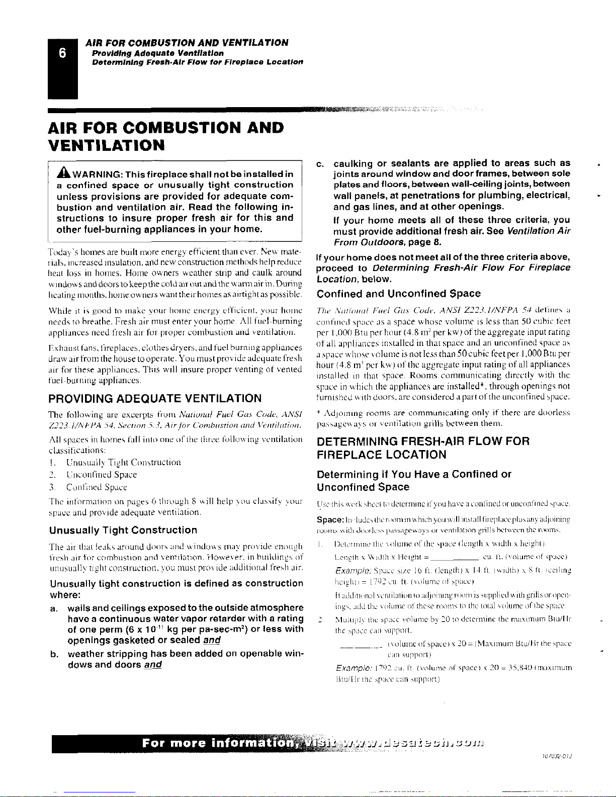
1.
Remove two screws that hold fireplace screen in place for ship-
ping. These screws are located near top of screen. Discard
screws. Lift fireplace scree: up and pull out to remove. Set
screen aside until installation
!Hs
been completed.
2.
Cut two plastic straps to remove the log from the firebox cavity.
3.
An optional blower is available.
Seedcressonies,
pages 38 and
39. Install optional blower now. Follow installation instruc-
tions provided with blower. See page 12 for Remote-Ready
Models or page 14 for Thermostat-Controlled Models.
Firebox Top
Sheet Metal Screws
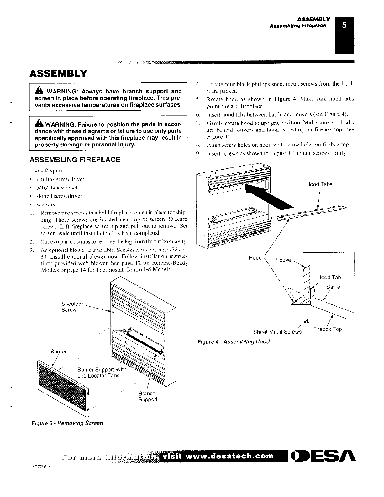
Figure 4 - Assembling Hood
ASSEMBLY
Assembling Fireplace
N4,MIUMINS.
ASSEMBLY
A
WARNING: Always have branch support and
screen in place before operating fireplace. This pre-
vents excessive temperatures on
fireplace surfaces.
A
WARNING: Failure to position the parts in accor-
dance with these diagrams or failure to use only parts
specifically approved with this fireplace may result in
property damage or personal injury.
ASSEMBLING FIREPLACE
4.
Locate four black phillips sheet metal screws from the hard-
ware packet.
5.
Rotate hood as shown in Figure 4. Make sure hood tabs
point toward fireplace.
6.
Insert hood tabs between baffle and louvers (see Figure 4).
7.
Gently rotate hood to upright position. Make sure hood tabs
are behind louvers and hood is resting on firebox top (see
Figure 4).
8.
Align screw holes on hood with screw holes on firebox top.
9.
Insert screws as shown in Figure 4. Tighten screws firmly.
Figure 3 - Removing Screen
u iiPitz; la! 91.4,114
visit www.desatech.com
•ESA
'07032-01.!
AIR FOR COMBUSTION AND VENTILATION
Providing Adequate Ventilation
Determining Fresh-Air Flow for Fireplace Location
AIR FOR COMBUSTION AND
VENTILATION
A
WARNING: This fireplace shall not be installed in
a confined space or unusually tight construction
unless provisions are provided for adequate com-
bustion and ventilation air. Read the following in-
structions to insure proper fresh air for this and
other fuel-burning appliances in your home.
Today's homes are built more energy efficient than ever. Nev mate-
rials,
increased insulation,
and new construction methods help reduce
heat loss in homes. Home owners weather strip and caulk around
windows and doors to keep the cold air out and the warm air in. During
heating months, home owners
want their
homes as antight
as possible.
While it is good to make your home energy efficient
your
home
needs to breathe. Fresh air must enter your borne. All fuel-burning
appliances need fresh air for proper combustion and ventilation.
Exhaust fans, fireplaces, clothes dryers, and fuel burning appliances
draw air from the house to operate. You must provide adequate fresh
air for these appliances. This will insure proper venting of vented
fuel-burning appliances.
PROVIDING ADEQUATE VENTILATION
The following
are excerpts from
National Fuel Gas Code, ANSI
21223. I/NEPA 54. Section 5.3, Air for Combustion and Ventilation.
All
spaces in homes fall
iron
one of he throe
following ventilation
classifications:
1.
Unusually Tight Construction
2.
Unconfined Space
3.
Confined Space
The information on pages 6 through S
V.
ill help you classify your
space and provide adequate ventilation.
Unusually Tight Construction
c. caulking or sealants are applied to areas such as
joints around window and door frames, between sole
plates and floors, between wall-ceiling joints, between
wall panels, at penetrations for plumbing, electrical,
and gas lines, and at other openings.
If your home meets all of these three criteria, you
must provide additional fresh air. See
Ventilation Air
From Outdoors,
page
8.
If your home does not meet all of the three criteria above,
proceed to
Determining Fresh-Air Flow For Fireplace
Location,
below.
Confined and Unconfined Space
The National Fuel Gus Code. ANSI Z223.1/NEPA 54
defines a
confined space as
a space whose volume is less than 50 cubic feet
per 1,000 Btu per hour (4.8 in' per kw) of the aggregate input rating
of all appliances installed in that space and an unconfined space as
a space whose volume is not less than 50 cubic feet per 1,000 Btu per
hour (4.8 in per kw) of the aggregate input rating of all appliances
installed in that space. Rooms communicating directly with the
space in which the appliances are installed*, through openings not
furnished with doors, are considered a part of the unconfined space.
Adjoining rooms
are communicating only
if there are doorless
passaged\ ays or ventilation grills between them.
DETERMINING FRESH-AIR FLOW FOR
FIREPLACE LOCATION
Determining if You Have a Confined or
Unconfined Space
Use this work sheet
to determine if you
have a confined or unconfined space.
Space:
Inaludes the
MOM
in which you will install
fireplace
plus any adjoinin2
rooms with rloorless passageways or ventilation grills between the rooms.
The
air that leaks around doors and windows may provide enough
I.
1)(2LT111111C the
‘olume of the space (length x width x
height))
fresh
air for combustion and vemilation. However, in buildings of
Length
x Width x Height =
cu. ft. (volume otspace)
unusually tight construction, you must provide additional fresh air.
Example:
Space size 16 ft. (length) x
14 P. (width)
S ft. ',Jain)]
Unusually tight construction is defined
as construction
height I =
1792 en tt. (volume
of space)
where:
If additional ventilation to achommic
10011115
supplied with
grillsoropen-
a.
walls and ceilings exposed to the outside atmosphere
ings, add the volume of these rooms
to die
total volume
of the space
have a continuous water vapor retarder with a
rating
2 Nlutuplv the space volume by 20 to
determine
the maximum Btuil
In
of one perm (6 x 1 0
-
" kg
per pa-sec-in') or less with
thc spnce can support.
openings
gasketed or sealed
and
volurnc
of space)
\ 20 = (Maximum Btud
-
ir the spice
b.
weather
stripping has been added on openable win-
can support)
dows and doors
and
Example:
1792
Cu. ft. (volume of space) x 20 4
35,840 (maximum
13tull hr the space can support)
For more informaitioni`',
4 1.,,t
:J sfr 31.1
(J,L:1)11J
107032-01J
AIR FOR COMBUSTION AND VENTILATION
Determining Fresh-Air Flow for Fireplace Location (Cont.)
Ventilation Air
AIR FOR COMBUSTION AND
VENTILATION
Continued
Add the Btu/I fr of all fuel burning appliances in the space.
Vent-free fireplace
Bt till Ir
Gas water heater* Btu/I fr
Gas
furnace
Btu/Hr
Vented gas heater
Bitt/Hr
Gas fireplace logs
Biu/Hr
Other gas appliances'
d-
Btu/Hr
Total
=
Btu/Hr
* Do not include direct
-
vent gas appliances. Direct
-
vent draws com-
bustion
air from the outdoors and vents to the outdoors.
Example:
Gas water heater
30
.
000
Rtii/Hr
Vent-free fireplace
+
10,000
Btu/Hr
Total
rz
40,000
Blu/l
Ir
4. Compare the maximum Btu/Ur the space can support with the actual
amount of Btu/Hr used.
Btu/Hr (maximum the space can support)
Btu/Hr (actual amount of Btudir used)
Example:
35,840 Btu/Hr (maximum the space can support)
40,000 Btu/Hr (actual amount of Btu/Hr used)
The space in the above example is a confined spac because the actual Btu/
Ir used is more than the maximum Btu/Hr the space can support. You must
provide additional fresh air. Your options are as follows:
A.
Rework worksheet, adding the space of an adjoining room. if the
extra space provides an unconfined space. remove door to adjoining
room or add ventilation grills between rooms. See
'owe/or/on Air Frain
Inside Building.
B.
Vent room directly to the outdoors. See
likaailtnion Air From Out-
doors.
page 8.
C.
Install a lower B tu/H r fireplace. if low er Btu/H r sOc makes coon,
unconfined.
the actual Btu/Hr used is less than the maximum Btu/Hr the space can support,
the space is an unconfined space. You will need no additional fresh air ventilation.
A
WARNING: If the area in which the fireplace
may
be operated is smaller than that defined as an uncon-
fined space or if the building is of unusually tight ,
construction, provide adequate combustion and ven-
tilation air by one of the methods described in the
National Fuel Gas Code, ANSI Z223.1/NFPA 54 Sec-
tion 5.3
or applicable local codes.
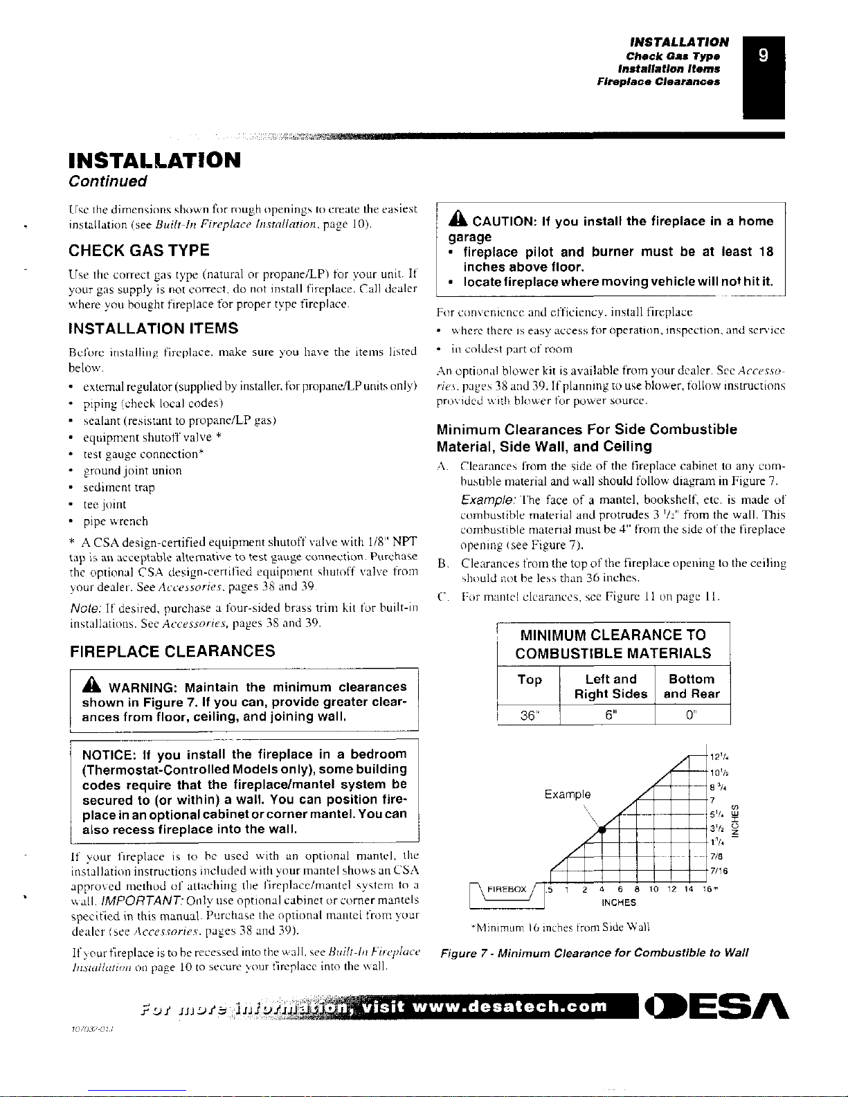
VENTILATION AIR
Ventilation Air From Inside Building
This fresh air would come from an adjoining
unconfined
space.
When ventilating to
an adjoining unconfined space, you must
provide two permanent openings: one within 12"
of
the ceiling and
one w ithin 12"
of the floor on the wall connecting
the two spaces
see options
I
and 2. Figure 5). You can also remove door into
adjoining room (see option 3. Figure 5). Follow the
National Fuel
Gcis Code, A
51.517223. l/NFPA 54, Section 5.3, Air for Combustion
and Ventilation
for
required size of ventilation grills or ducts.
.0
---,DA
--
V
ent,Iai3O0 O
nlii
Int
o Ad p A
corn.
Op
II
or
A
g
R m
Roo
Doo
r
c
Adjornng
o
n
...
•1.A.N
Figure 5- Ventilation Air from Inside Building
,
.1
7
visit www.desatech.com
CIDESA
:'07032-01i
INSTALLATION
Check Gas Type
Installation Items
Fireplace Clearances
INSTALLATION
Continued
Use the dimensions shown for rough openings to create the easiest
installation (see
Built-In Fireplace Installation.
page 10).
CHECK GAS TYPE
Use the correct gas type (natural or propane/LP) for your unit. If
your gas supply is not correct, do not install fireplace. Call dealer
where you bought fireplace for proper type fireplace.
INSTALLATION ITEMS
Before installing fireplace, make sure you have the items listed
below.
•
external regulator (supplied by installer, for propane/LP units only)
•
piping (check local codes)
•
sealant (resistant to propane/LP gas)
•
equipment shutoff valve *
•
test gauge connection*
•
ground joint union
•
sediment trap
•
tee joint
•
pipe wrench
* A CSA design-certified equipment shutoff valve with 1/8" NPT
tap is an acceptable alternative to test gauge connection. Purchase
the optional CSA design-certified equipment shutoff valve from
your dealer. See
Accessories.
pages 38 and 39.
Note:
If desired, purchase a four-sided brass trim kit for built-in
installations. See
Accessories,
pages 38 and 39.
FIREPLACE CLEARANCES
A
WARNING: Maintain the minimum clearances
shown in Figure 7. If you can, provide greater clear-
ances from floor, ceiling, and joining wall.
NOTICE: If you install the fireplace in a bedroom
(Thermostat-Controlled Models only), some building
codes require that the fireplace/mantel system be
secured to (or within) a wall. You can position fire-
place in an optional cabinet or corner mantel. You can
also recess fireplace into the wall.
If your fireplace is to be used with an optional mantel, the
installation instructions included with your mantel shows an ESA
approved method of attaching the l'ireplace/mantel system to a
wall.
IMPORTANT:
Only use optional cabinet or corner mantels
specified in this manual. Purchase the optional mantel from your
dealer (see
Accessories.
pages 38 and 39).
If your fireplace is to be recessed into the wall, see
Built-In Fireplace
Installation
00 page 10 to secure your fireplace into the wall.
A
CAUTION: If you install the fireplace in a home
garage
•
fireplace pilot and burner must be at least 18
inches above floor.
•
locate fireplace where moving vehicle will not hit it.
For convenience and efficiency. install fireplace
•
where there is easy
access for operation, inspection,
and
SCINICe
•
in coldest part of room
An optional blower kit is available from your dealer. See
Accesso-
ries.
pages 38 and 39.11 planning to use blower, follow instructions
provided with blower for power source.
Minimum Clearances For Side Combustible
Material, Side Wall, and Ceiling
A.
Clearances from the side of the fireplace cabinet to any com-
bustible material and wall should follow diagram in Figure 7.
Example:
The face of a mantel, bookshelf, etc. is made of
combustible material and protrudes 3
1
/2"
from the wall. This
combustible material must be 4" from the side of the fireplace
opening (see Figure 7).
B.
Clearances from the top of the fireplace opening to the ceiling
should not he less than 36 inches.
C.
For mantel clearances, see Figure 11 on page 11.
MINIMUM CLEARANCE TO
COMBUSTIBLE MATERIALS
Top
Left and
Bottom
Right Sides and Rear
■
36"
6"
0"
12
1
/4
1002
Example
8 30
nn
rani 7/8
MMMMMM
7/16
1
1
/4
4 6 8 10 12 14 16*
FIREBOX
IN
•
Nfinimum lb
inches from Side Wall
Figure 7- Minimum Clearance for Combustible to Wall
*if Lit :)/ iithit
4
,
•11
0
visit www.desatech.com
MESA
10 7032- 0
INSTALLATION
Built-In Fireplace Installation
NaillikalittiliklaRatttadnAls,
INSTALLATION
Continued
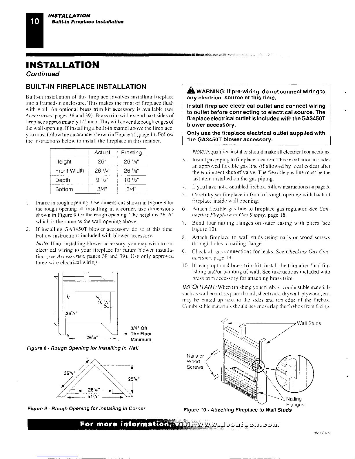
BUILT-IN FIREPLACE INSTALLATION
Built-in installation of this fireplace involves installing fireplace
into a framed-in enclosure. This makes the front of fireplace flush
with wall. An optional brass trim kit accessory is available (see
Accessories',
pages 38 and 39). Brass trim will extend past sides of
fireplace approximately 1/2 inch. This will cover the rough edges of
the wall opening. If installing a built-in mantel above the fireplace,
you must follow the clearances shown in Figure II ,page 11. Follow
the instructions below to install the fireplace in this manner.
'
Actual
•
Framig
Height
26" .
261t
Front Width
263/4"
•
267/5"
Depth
9 I/2"
101/2"
Bottom
3/4"
3/4"
1.
Frame in rough opening. Use dimensions shown in Figure 8 for
the rough opening. If installing in a corner, use dimensions
shown in Figure 9 for the rough opening. The height is 26
7
/s"
which is the same as the wall opening above.
2.
If installing GA3450T blower accessory, do so at this time.
Follow instructions included with blower accessory.
Note:
If not installing blower accessory, you may wish to run
electrical wiring to your fireplace for future blower installa-
tion (see
Accessories.
pages 38 and 39). Use only approved
three-wire electrical wiring.
10 Itin
A
WARNING: If pre-wiring, do not connect wiring to
any electrical source at this time.
Install fireplace electrical outlet and connect wiring
to outlet before connecting to electrical source. The
fireplace electrical outlet is included with the GA3450T
blower accessory.
Only use the fireplace electrical outlet supplied with
the GA34507 blower accessory.
Note:
A qualified installer should make all electrical connections.
3.
Install gas piping to fireplace location. This installation includes
all approved flexible gas line (if allowed by local codes) after
the equipment shutoff valve. The flexible gas line must be the
last itern installed on the gas piping.
4.
If you have not assembled firebox, follow instmetions on page 5.
5.
Carefully set fireplace in front of rough opening with back of
Ii replace inside wall
opening.
6.
Attach flexible gas line to fireplace gas regulator. See
Con-
necting Fireplace to Gas Supply,
page 18.
7.
Bend four nailing flanges on outer casing with pliers (see
Figure
It)).
S. Attach fireplace to wall studs using nails or wood screws
through holes in nailing flange.
9. Check all gas connections for leaks. See
Checking Gas Con-
nections.
page 19.
W. If using
optional brass trim kit, install the trim after final fin-
ishing and/or painting of wall. See instructions included with
brass trim accessory for attaching brass trim.
IMPORTANT:
When finishing your firebox, combustible materials
such as all board. gypsum board, sheet rock, drywall, plywood, etc.
inay he hinted up
next
to the sides and top edge of the firebox.
Combusshle materials should
never
-
overlapthe
firehox front facing.
3/4" Off
•
The Floor
26718"
Minimum
ads
Figure 8- Rough Opening for Installing in Wall
36
5
/a"
26'fi."
51
3
/4“
Nails or
Wood
Screws \
Figure 9-
Rough Opening for Installing in Corner
Figure 10 - Attaching Fireplace to Wall
Studs
For more information,
z
INSTALLATION
Built-In Fireplace Installation (Cont.)
Optional Mantel Installation
INSTALLATION
Continued
A
WARNING: Do not allow any combustible materi-
NOTICE: If your installation does not meet the mini-
,
als to overlap the firebox front facing,
mum clearances shown, you must do one of the
,
following:
IMPORTANT:
Noncombustible materials such as brick, tile, etc.
•
raise the mantel to an acceptable height
may overlap the front facing, but should never cover any necessary
•
remove the mantel
openings nice touvereu slots.
A
WARNING: Do not allow noncombustible materials
to cover any necessary openings like louvered slots.
A
WARNING: Never modify or cover the louvered
slots on the front of the firebox.
A
WARNING: Use only noncombustible mortar or
adhesives when overlapping the front facing with
noncombustible facing
material.
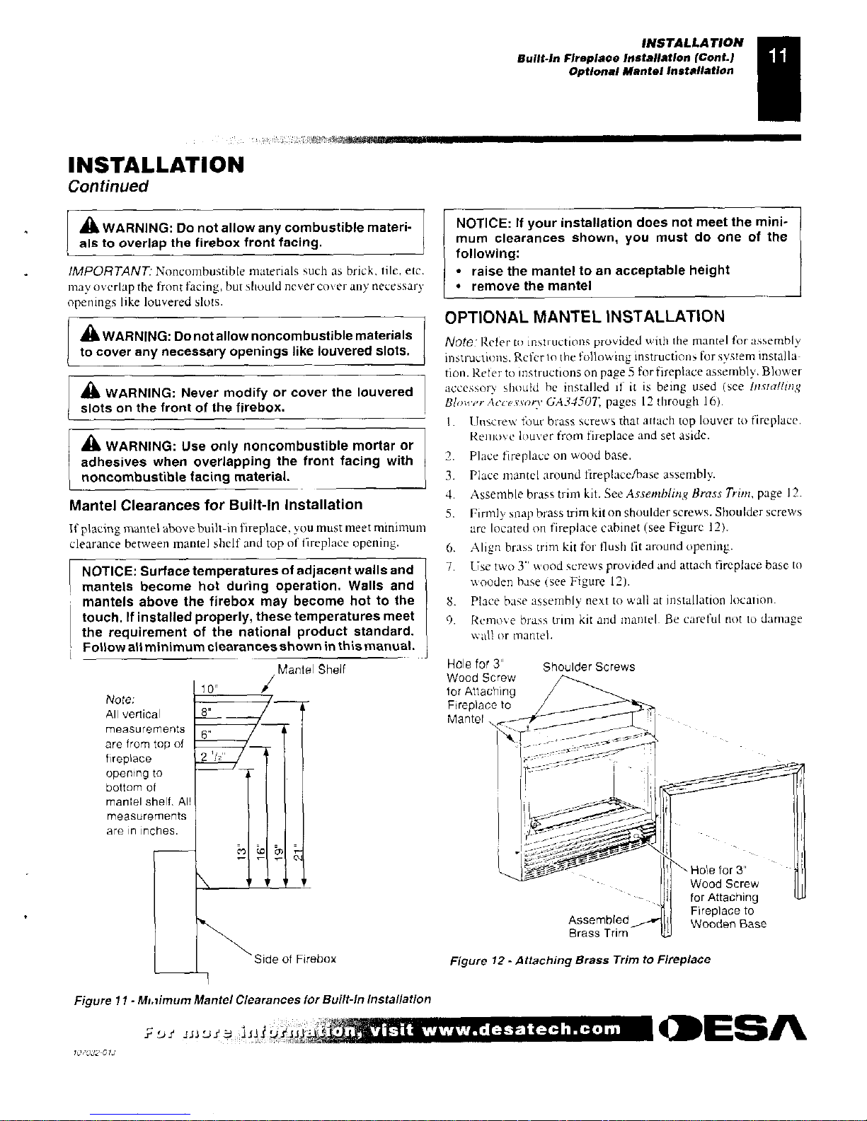
Mantel Clearances for Built-In Installation
If placing mantel above built-in fireplace, you must meet minimum
clearance between mantel shelf and top of fireplace opening.
NOTICE:
Surface temperatures of adjacent walls and
mantels become hot during operation. Walls and
mantels above the firebox may become hot to the
touch. If installed properly, these temperatures meet
the requirement of the national product standard.
Follow all minimum clearances shown in this manual.
Mantel Shelf
Note:
All vertical
measurements
are from top of
fireplace
opening to
bottom of
mantel shelf. All
measurements
are in inches.
OPTIONAL MANTEL INSTALLATION
Note:
Refer to instructions provided with the mantel for assembly
instructions. Refer to the following instructions for system installa-
tion. Refer to instructions on page 5 for fireplace assembly. Blower
accessory should be installed if it is being used (see
Installing
Blower Accesvory GA34507:
pages 12 through 16).
1.
Unscrew four brass
Screws
that attach top louver to fireplace.
Remove louver from fireplace and set aside.
2.
Place fireplace on wood base.
3.
Place mantel around fireplace/base assembly.
4.
Assemble brass trim kit. See
Assembling Brass Trim,
page 12.
5.
Firmly snap brass trim kit on shoulder screws. Shoulder screws
are located on fireplace cabinet (see Figure 12).
6.
Align brass trim kit for flush fit around opening.
7.
Use two 3" wood screws provided and attach fireplace base to
wooden base (see Figure 12).
8.
Place base assembly next to wall at installation location.
9.
Remove brass trim kit and mantel. Be careful not to damage
wall or mantel.
Hole for 3"
Shoulder Screws
Wood Screw
for Attaching
Fireplace to
Mantel
lair 8:4_
i 'Ns Hole for 3'
.
I
Wood Screw
..
" --- .
I
..
for Attaching
,
1
Assembled
Fireplace to
I Wooden Base
Brass Trim
Side of Firebox
Figure 12 - Attaching Brass Trim to Fireplace
Figure 11 -
M1,71177UM
Mantel Clearances for Built-In Installation
1111.32 '15.11p.ii,,
a
g„inil;
visit www.desatech.corn
CDESA
ILIG.132 GI,
INSTALLATION
Optional Mantel Installation (Cont.)
Installing Blower Accessory GA34507" in Remote-Ready Models
INSTALLATION
Continued
10.
Attach wood base to floor with two 1 3/4'' black screws pro-
vided
(see
Figure 13). lithe floor is concrete use anchor method
(see
Attaching Wood Base
to Solid Floor,
page 17).
11.
Install gas line. See
Connecting
To Gas Supply,
pages 17 and IS.
12.
Check for leaks. See
Checking
Gas Connections,
page 19.
13.
Place mantel around fireplace. Be careful not to damage wall
or mantel.
14.
Place brass trim kit on the shoulder screws located on the side
and top of the fireplace. Firmly snap the brass trim over the
shoulder screws on fireplace (see Figure 12, page 11).
15.
Adjust assembly to remove any gaps. Attach remaining two 3''
wood screws from hardware pack through openings inside of
fireplace sides into the mantel. The openings are located at top
behind the area for the brass louvers (see Figure 12, page II).
16.
Reinstall top brass louvers.
Set
Screws
Adjusting
/
Top Brass Trim
Plate
Slot
Mitered Edge
Side Brass Trim—'
Figure 14 - Assembling Brass Trim
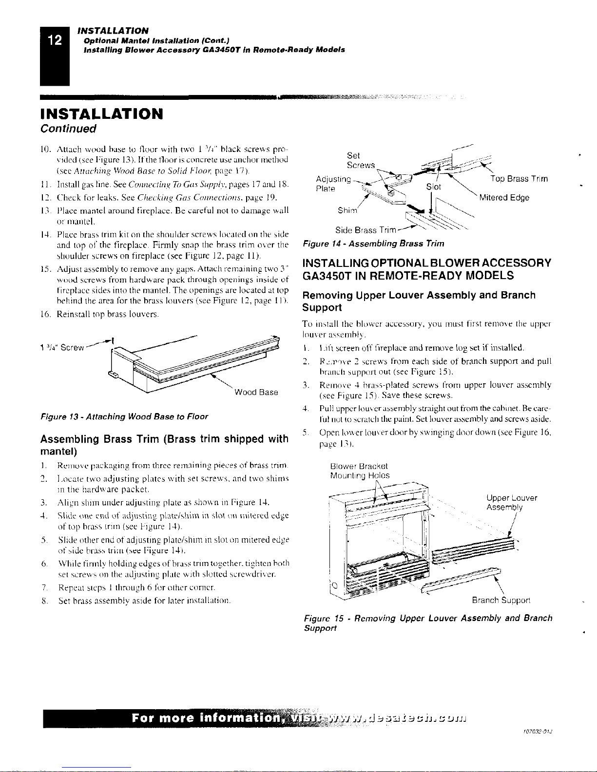
INSTALLING OPTIONAL BLOWER ACCESSORY
GA3450T IN REMOTE-READY MODELS
Removing Upper Louver Assembly and Branch
Support
To install the blower accessory, you must first remove the upper
louver assembly.
1 3/4"
Screw
...-----
_..--
i'\
•••••••
•0
101........111.1
---
----
----
------
—
Wood Base
Figure 13 - Attaching Wood Base to Floor
Assembling Brass Trim (Brass trim shipped with
mantel)
Remove packaging from three remaining pieces of brass (rim.
2.
Locate two adjUSting plates with set screws, and two shims
in the hardware packet.
3.
Align shim under adjusting plate as shown in Figure 14.
4.
Slide one end of adjusting plate/shim in slot on mitered edge
of top brass trim (see Hgure 14).
5.
Slide other end of adjusting plate/shim in slot on mitered edge
of side brass trim (see Figure 14).
6.
While firmly holding edges of brass trim together. tighten both
set screws on the adjusting plate with slotted screwdriver.
7.
Repeat steps 1 through 6 for other corner.
S.
Set brass assembly aside for later installation.
I. Lift screen off fireplace and
2.
P
i,PON
e
2 screws from each
branch support out (see Figure
3.
Remove 4 brass-plated
Screws
(see Figure 15). Save these
4.
Pull upper louver assembly straight
ful not to scratch the paint. Set
5.
Open lower louver door by
page I 3 I.
Blower Bracket
Mounting Holes
Lii—il
iill—t?
I
Se'
e
-
remove log set if installed.
side of branch support and pull
15).
from upper louver assembly
screws.
out from the cabinet. Be care-
louver assembly and screws aside.
swinging door down (see Figure 16,
I
Upper Louver
Assembly
,
I
I
Branch Support
Figure 15 - Removing Upper Louver Assembly and Branch
Support
For more information,'
107032-01J
INSTALLATION
Installing Blower Accessory GA34507 in Remote-Ready Models (Cont)
INSTALLATION
Continued
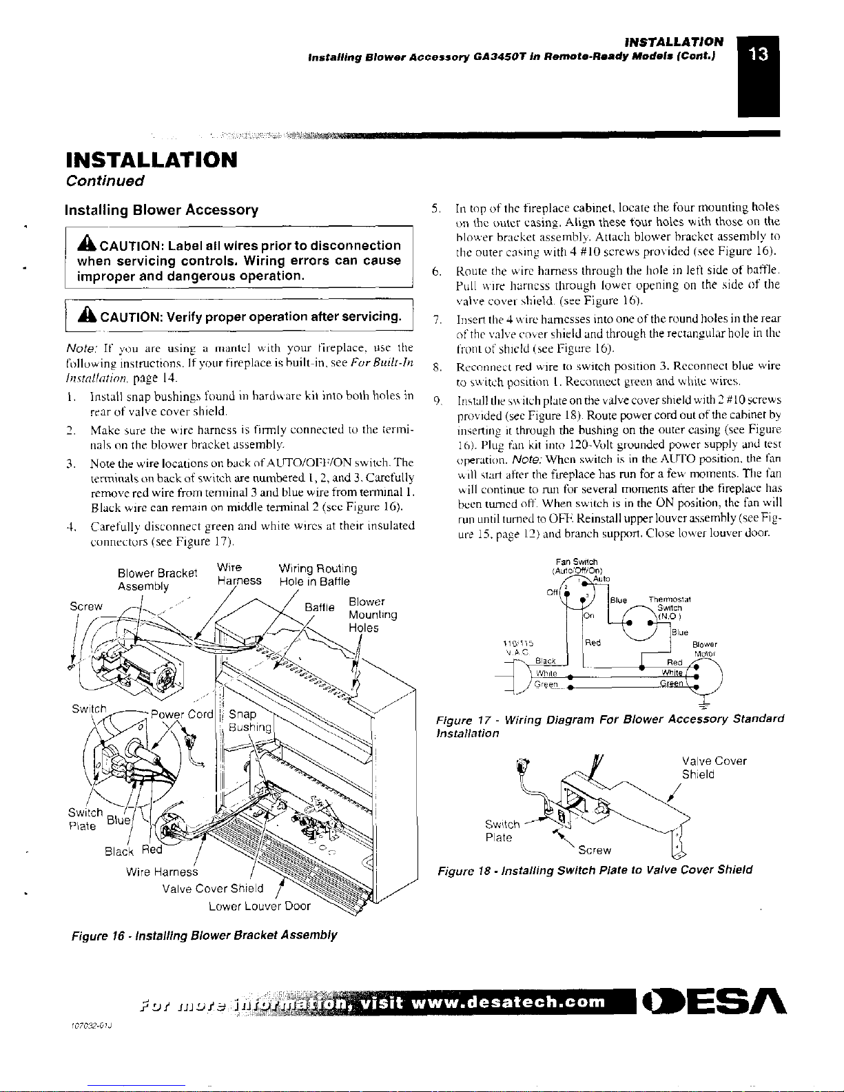
Installing Blower Accessory
A
CAUTION:
Label all wires prior to disconnection
when servicing controls. Wiring errors can cause
improper and dangerous operation.
A
CAUTION: Verify proper operation after servicing.
Note:
If you are using a mantel with your fireplace, use the
Following instructions. If your fireplace is built-in, see
For Built-1n
Installation,
page 14_
1.
Install snap bushings found in hardware kit into both holes in
rear of valve cover shield.
2.
Make sure the wire harness is firmly connected to the termi-
nals on the blower bracket assembly.
3.
Note the wire locations on back of AUTO/OFF/ON switch. The
terminals on back of switch are numbered 1,2, and 3, Carefully
remove red wire from terminal 3 and blue wire from terminal 1.
Black wire can remain on middle terminal 2 (sec Figure 16).
4.
Carefully disconnect green and white wires at their insulated
connectors (see Figure 17).
Blower Bracket
Wire
Wiring Routing
Assembly
Harness Hole in Baffle
Blower
Screw
-
I
Bathe
Mounting
Snap
5.
In top of the fireplace cabinet, locate the four mounting holes
on the outer easing. Align these tour holes with those on the
blower bracket assembly. Attach blower bracket assembly to
the outer casing with 4 #10 screws provided (see Figure 16).
6.
Route the wire harness through the hole in left side of baffle.
Pull wire harness through lower opening on the side
of the
valve cover shield. (see Figure 16).
7.
Insert the 4 wire harnesses into one of the round holes in the rear
of the valve cover shield and through the rectangular hole in the
Front of shield (see Figure 16).
8.
Reconnect red wire to switch position 3. Reconnect blue wire
to switch position t . Reconnect green and white wires.
9.
Install the switch plate on the valve cover shield with 2 #I0 screws
provided (see Figure 18). Route power cord out of the cabinet by
inserting it through the bushing on the outer casing (see Figure
16). Plug fan kit into 120-Volt grounded power supply and test
operation.
Note:
When switch is in the AUTO position, the fan
will start after the fireplace has run for a few moments. The fan
ill continue to run for several moments after the fireplace has
been turned off. When switch is in the ON position, the fan will
run until turned to OFF. Reinstall upper louver assembly (see Fig-
ure 15, page 12) and branch support. Close lower louver door.
Figure 17 - Wiring Diagram For Blower Accessory Standard
Installation
Plate
Black Red —
Switcl
Plate
alve Cover
hield
Wire Harness
Figure 18 - Installing Switch Plate to Valve Cover Shield
Valve Cover Shield
Lower Louver Door
Figure 16
-
Installing Blower Bracket Assembly
Lli
LIJILeS
1044
,
oth visit
www.desatech.com
*ESA
107032-C1J
INSTALLATION
Installing Blower Accessory GA3450T in Remote-Ready Models (Cont.)
Installing Blower Accessory GA3450T In Thermostat-Controlled Models
INSTALLATION
Continued
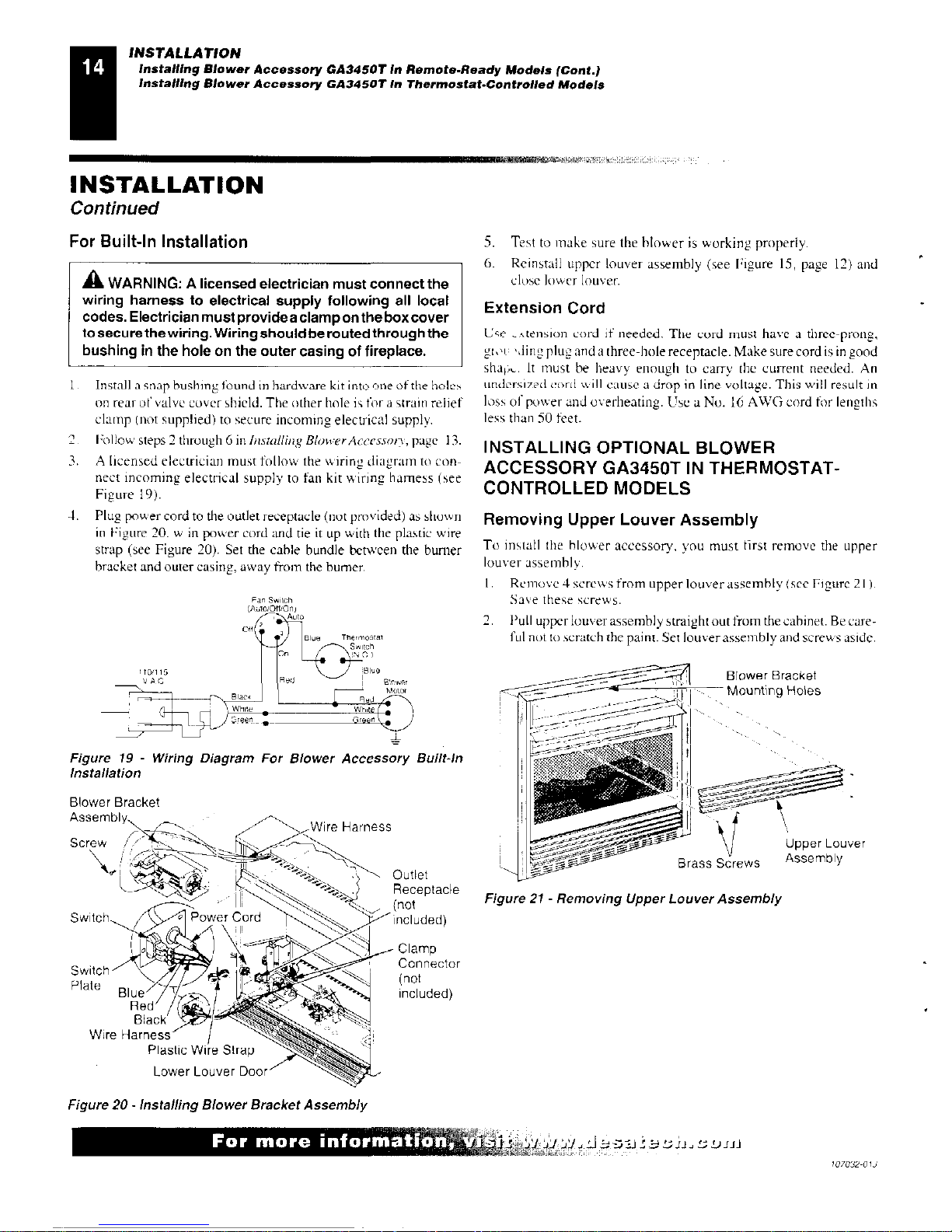
For Built-In Installation
A
WARNING: A licensed electrician must connect the
wiring harness to electrical supply following all local
codes. Electrician must provides clamp on the box cover
to secure the wiring. Wiring should be routed through the
bushing in the hole on the outer
casing of fireplace.
1
Install a snap bushing found in hardware kit into one of the holes
on rear of valve cover shield. The other hole is for a strain relief
clamp (not supplied) to secure incoming electrical supply.
2
Follow steps 2 through 6 in
Installing Blower Accessory,
page 13.
3.
A licensed electrician must follow the wiring diagram to con-
nect incoming electrical supply to fan kit wiring harness (see
Figure 19).
4.
Plug power cord to the outlet receptacle (not provided) as shown
in Figure 20. w in power cord and tie it up
with
the plastic wire
strap (see Figure 20). Set the cable bundle between the burner
bracket and outer casing, away from the burner.
Figure 19 - Wiring Diagram For Blower Accessory Built-In
Installation
5.
Test to make sure the blower is working properly.
6.
Reinstall upper louver assembly (see Figure 15, page 12) and
close lower louver.
Extension Cord
Use _A tension cord if needed. The cord must have a three-prong,
gt,ic 'ding plug and a three-hole receptacle. Make sure cord is in good
shak„. It must be heavy enough to carry the current needed. An
undarsims(I coni will cause a drop in line voltage. This will result in
loss of power and overheating. Use a No. 16 AWG cord for lengths
less than 50 feet.
INSTALLING OPTIONAL BLOWER
ACCESSORY GA3450T IN THERMOSTAT-
CONTROLLED MODELS
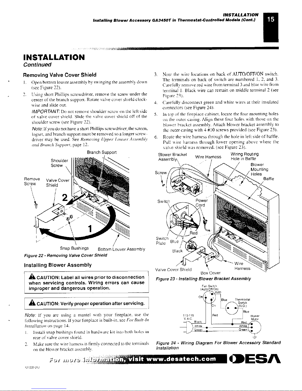
Removing Upper Louver Assembly
To install the blower accessory, you must first remove the upper
louver assembly,
I.
Remove 4 screws from upper louver assembly (see
Figure 211,
Save these screws.
2. Pull upper louver assembly straight out from the cabinet. Be care-
ful not to scratch the paint. Set louver assembly and screws aside.
Blower Bracket
Mounting Holes
11
V
Upper Louver
Assembly
Outlet
Brass Screws
Receptacle
(not
Figure 21 - Removing Upper Louver Assembly
Included)
Clamp
Connector
(not
included)
Blower Bracket
Screw /.
E
-
,---- 'n-,„Wire Harness
e I \
0 Power
Cord
Switch
- rz--4,
.. n
Plate
Wire
Plastic Wire Strap
-"----,\
:- -,. ---
Lower Louver Door
Figure 20 - Installing Blower Bracket Assembly
For more informatiaii;'
4 4,
.f:DJJJ
107032-Old
INSTALLATION
Installing Blower Accessory GA34507 in Thermostat-Controlled Models (Cont.)
INSTALLATION
Continued
Removing Valve Cover Shield
1.
Open bottom louver assembly by swinging the assembly down
(see Figure 22).
2.
Using short Phillips screwdriver, remove the screw under the
center of the branch support. Rotate valve cover shield clock-
wise and slide out.
IMPORTANT.' Do
not remove shoulder
SCFCNV
on the kit side
of valve cover shield. Slide the valve cover shield off of the
shoulder screw (see Figure 22).
Note:If
you do not have a short Phillips screwdriver, the screen,
logset, and branch support must be removed so a longer screw-
driver may be used. See
Removing tipper Louver Assembly
and Branch Support,
page 12.
Branch Support
Shoulder
Screw ,
k
g-
L
Remove Valve Cover [...
:::1
Screw
Shield
\
\
L
2 • _,
,,--
,
,. ..•
,
. -
40 -,
•-•:,
•••
-•
1
...
..-----
1
Snap Bushings
Bottom Louver Assembly
Figure 22- Removing Valve Cover Shield
Installing Blower Assembly
A
CAUTION: Label all wires prior to disconnection
when servicing controls. Wiring errors can cause
improper and dangerous operation.
A
CAUTION: Verify proper operation after servicing.
Note:
If you are using a mantel with your fireplace, use the
following instructions. If your fireplace is built-in, see
For Built-hi
Installation
on page 14.
Install snap bushings found in hardware kit into both holes in
rear of valve cover shield.
2. Make sure the wire harness is firmly connected to the terminals
on the blower bracket assembly.
3.
Note the wire locations on hack of AUTO/OFF/ON switch.
The terminals on back of switch are numbered 1, 2, and 3.
Carefully remove red wire from terminal 3 and blue wire from
terminal 1. Black wire can remain on middle terminal 2
(see
Figure 23).
4.
Carefully disconnect green and white wires at their insulated
connectors (see Figure 24).
5.
In top of the fireplace cabinet, locate the four mounting holes
on the outer casing. Align these four holes with those on the
blower bracket assembly. Attach blower bracket assembly to
the outer casing with 4 #10 screws provided (see Figure 23).
6.
Route the wire harness through the hole in left side of baffle.
Pull
,
A
ire harness through lower opening above where the
valve shield was removed. (see Figure 23).
Blower Bracket
Wiring Routing
Wire Harness
Assembly
Hole in Baffle
,
,
Blower
W
Screw
,r. --
I.,
O
i
iMounting
II
Baffle
or
IA-
1->1 ,
151
--• -Thr•-- - ,.. ' • -........
"./C
Switch
Power
Switch
7
72'
Plate Blue
Black
v-
Wire ''-
Valve Cover Shield
Harness
Box
Cover
Figure 23 - Installing Blower Bracket Assembly
Figure 24 - Wiring Diagram For Blower Accessory Standard
Installation
;Di
inDie
.n visit www.desatech.com
MESA.
107032 -012
INSTALLATION
Installing Blower Accessory GA3450T in Thermostat-Controlled Models (Cont.)
INSTALLATION
Continued
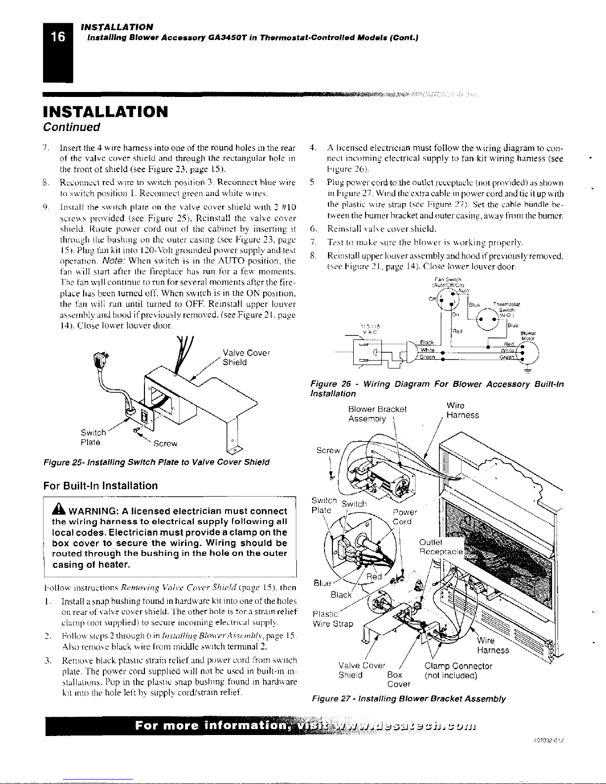
7.
Insert the 4 wire harness into one of the round holes in the rear
of the valve cover shield and through the rectangular hole in
the front of shield (see Figure 23, page 15).
S. Reconnect red wire to switch position 3. Reconnect blue wire
to switch position 1. Reconnect green and white wires.
9. Install
the switch plate on the valve cover
shield with 2 #10
screws provided (see Figure 25). Reinstall the valve cover
shield. Route power cord out of the cabinet by inserting it
through the bushing on the outer casing (see Figure 23, page
15). Plug fan kit into 120-Volt grounded power supply and test
operation.
Note:
When switch is in the AUTO position, the
fan will start after the fireplace has run for a few moments.
The fan will continue to run for several moments after the fire-
place has been turned off. When switch is in the ON position,
the fan will ran until turned to OFF. Reinstall upper louver
assembly and hood if previously removed. (see Figure 21, page
14). Close lower louver door.
Valve Cover
Shield
4. A licensed electrician must follow the wiring diagram to con-
nect incoming electrical supply to fan kit wiring harness (see
Figure 26).
Plug power cord
to the outlet receptacle (not provided) as shown
in Figure 27.
Wind
the extra cable in power cord and tie it up with
the plastic \s ire strap
(see
Figure 27). Set the cable bundle
be-
tween
the burner bracket and outer casing, away from the burner.
6.
Reinstall valve cover shield.
7.
Test to make
sure
the blower is working properly.
S. Reinstall upper louver assembly and hood if previously removed.
(see Figure
21,
page 14). Close lower louver door.
Figure 26 - Wiring Diagram For Blower Accessory Built-In
Installation
Switch
Plate
Screw
Figure 25- Installing Switch Plate to Valve Cover Shield
For Built-In Installation
A
WARNING: A licensed electrician must connect
the wiring harness to electrical supply following all
local codes. Electrician must provide a clamp on the
box cover to secure the wiring. Wiring should be
routed through the bushing in the hole on the outer
casing of heater.
Screw
k I
Switch
Plate
Blower Bracket
Assembly \
Wire
Harness
Follow instructions
Removing Valve Cover Shield
(page 15), then
Install a snap bushing found in hardware kit into one of the holes
on
rear of valve cover shield. The other
hole is for a strain relief
clamp not supplied) to secure incoming electrical supply.
2.
Follow steps
2 through 6 in
Installing Blower Assembly,
page 15.
Also remove black wire from middle switch terminal 2.
3.
Remove black plastic strain relief and power cord from switch
plate. The power cord supplied will not be used in built-in in-
stallations. Pop in the plastic snap bushing found in hardware
kit into the hole left by supply cord/strain relief
Plastic -
Wire Strap
Valve Cover
caamp isonnector
Shield
Box
(not included)
Cover
Figure 27- Installing Blower Bracket Assembly
For more information, t ?0
,4,4/47
/,;j
ch
.3-Lise,z/J,L;Din
107032-01,1
 Loading...