

Desa VS18NV, CFS30NVA, CFS24NVA, VS30NVA, VL18NTA Owner's Operating & Installation Manual
...
DESA INTERNATIONAL
LO
PILOT
OFF
HI
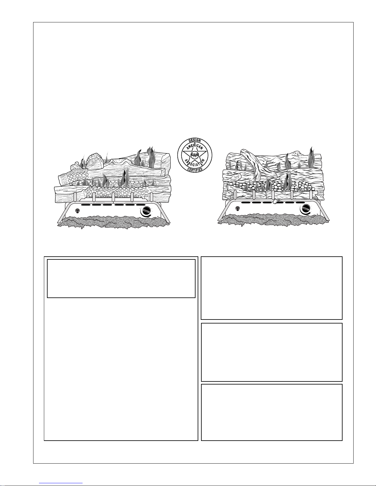
UNVENTED (VENT-FREE)
PROPANE GAS LOG HEATER
Manually Control Models Also Designed Certified as V ented Decorative Appliance)
This appliance may be installed in an aftermarket* manufactured (mobile) home,
where not prohibited by state or local codes.
* Aftermarket: Completion of sale, not for purpose of resale, from the manufacturer
OWNER’S OPERATION AND INSTALLATION MANUAL
SPLIT OAK DESIGN
LO
PILOT
OFF
HI
18" (Non “A” Model), 24", and 30"
(“A” Models) Variable Manually-Controlled
and (“A” Models) Thermostatically Controlled
WARNING: If the information in this manual is
not followed exactly, a fire or explosion may
result causing property damage, personal
injury, or loss of life.
— Do not store or use gasoline or other
flammable vapors and liquids in the vicinity
of this or any other appliance.
— WHAT TO DO IF YOU SMELL GAS
• Do not try to light any appliance.
• Do not touch any electrical switch; do
not use any phone in your building.
• Immediately call your gas supplier from
a neighbor’s phone. Follow the gas
supplier’s instructions.
• If you cannot reach your gas supplier,
call the fire department.
— Installation and service must be per-
formed by a qualified installer, service
agency, or the gas supplier.
ST ANDARD OAK DESIGN
®
18", 24", and 30"
(“A” Models) Thermostatically-Controlled
WARNING: Improper installation, adjustment,
alteration, service, or maintenance can cause
injury or property damage. Refer to this
manual for correct installation and operational procedures. For assistance or additional information consult a qualified installer,
service agency, or the gas supplier.
WARNING: This gas log set is for installation in a masonry solid fuel burning fireplace, a U.L. listed manufactured solid fuel
burning fireplace or an AGA design certified vent-free firebox (including LogMate
FB32C and FB32NC) listed for use with
these gas log models .
WARNING: This is an unvented gas-fired
heater. It uses air (oxygen) from the room in
which it is installed. Provisions for adequate
combustion and ventilation air must be
provided. Refer to “Air for Combustion and
Ventilation” section in this manual.
Save this manual for future reference.
CONTENTS
SECTION PAGE
Safety Information................................................................................... 2
Product Identification .............................................................................. 4
Local Codes ............................................................................................. 5
Unpacking................................................................................................ 5
Product Features ...................................................................................... 5
Air for Combustion and Ventilation........................................................ 5
Installing .................................................................................................. 9
Check Gas Type ............................................................................... 9
Installation and Clearances (Vent-Free Operation Only)................. 10
Installing Damper Clamp Accessory for Vented Operation ............ 14
Installing Heater Base Assembly ..................................................... 15
Connecting to Gas Supply................................................................ 16
Checking Gas Connections .............................................................. 18
Installing Logs.................................................................................. 20
Operating Heater (Thermostat-Controlled Models) ................................ 22
Operating Heater (Manually-Controlled Models) ................................... 24
Inspecting Burners................................................................................... 27
Cleaning and Maintenance ...................................................................... 28
Troubleshooting....................................................................................... 28
Optional Positioning of Thermostat Sensing Bulb .................................. 32
Technical Service .................................................................................... 34
Specifications .......................................................................................... 34
Service Hints ........................................................................................... 34
Replacn/ent Parts ................................................................................... 35
Accessories .............................................................................................. 35
Illustrated Parts Lists ............................................................................... 36-41
Warranty Information .............................................................................. Back Cover
SAFETY
INFORMATION
2
W ARNINGS
WARNING ICON G 001
IMPORTANT: Read this owner’s manual carefully and completely before
trying to assemble, operate, or service this heater. Improper use of this
heater can cause serious injury or death from burns, fire, explosion,
electrical shock, and carbon monoxide poisoning.
DANGER
WARNING ICON G 001
Carbon monoxide poisoning may lead to death!
Carbon Monoxide Poisoning: Early signs of carbon monoxide poisoning resemble
the flu, with headaches, dizziness, or nausea. If you have these signs, the heater may not
be working properly. Get fresh air at once! Have heater serviced. Some people are more
affected by carbon monoxide than others. These include pregnant women, people with
heart or lung disease or anemia, those under the influence of alcohol, and those at high
altitudes.
Propane Gas: Propane gas is odorless. An odor-making agent is added to the gas. The
odor helps you detect a gas leak. However, the odor added to the gas can fade. Gas may be
present even though no odor exists.
Make certain you read and understand all Warnings. Keep this manual for reference. It is
your guide to safe and proper operation of this heater.
Safety Information continues on next page
102653
SAFETY
INFORMATION
Continued
102653
W ARNINGS
WARNING: Any change to this heater or its controls can be dangerous.
1. This appliance is only for use with the type of gas indicated on the rating plate. This
appliance is not convertible for use with other gases.
2. Do not place propane supply tank(s) inside any structure. Locate propane supply tank(s) outdoors.
3. If you smell gas
• shut off gas supply
• do not try to light any appliance
• do not touch any electrical switch; do not use any phone in your building
• immediately call your gas supplier from a neighbor’s phone. Follow the gas supplier’s
instructions
• if you cannot reach your gas supplier, call the fire department
4. This heater shall not be installed in a bedroom or bathroom.
5. Never install the heater
• in a recreational vehicle
• where curtains, furniture, clothing, or other flammable objects are less than 36 inches
from the front, top, or sides of the heater
• in high traffic areas
• in windy or drafty areas
6. Before installing in a solid fuel burning fireplace, the chimney flue and firebox must be
cleaned of soot, creosote, ashes and loose paint by a qualified chimney cleaner. Creosote
will ignite if highly heated. Inspect chimney flue for damage. If damaged, operate heater
with flue damper closed.
7. If fireplace has glass doors, never operate this heater with glass doors closed. If you operate
heater with doors closed, heat buildup inside fireplace will cause glass to burst. Also if
fireplace opening has vents at the bottom, you must open the vents before operating heater.
8. You must operate this heater with a fireplace screen in place. Make sure fireplace screen
is closed before running heater.
9. This log heater is designed to be smokeless. If logs ever appear to smoke, turn off heater
and call a qualified service person.
occur due to log curing and heater burning manufacturing residues.
10. Do not allow fans to blow directly into the fireplace. Avoid any drafts that alter burner
flame patterns. Ceiling fans may create drafts that alter burner flame patterns. Altered
burner patterns can cause sooting.
11. Do not use a blower insert, heat exchanger insert or other accessory not approved for use
with this heater.
12. This heater needs fresh, outside air ventilation to run properly. This heater has an oxygen
depletion sensor (ODS) pilot light safety system. The ODS shuts down the heater if not
enough fresh air is available. See Air for Combustion and Ventilation, pages 5 through 8.
If heater keeps shutting off, see Troubleshooting, pages 28 through 31.
13. Do not run heater
• where flammable liquids or vapors are used or stored
• under dusty conditions
14. Do not use this heater to cook food or burn paper or other objects.
15. Never place any objects on the heater.
16. Heater base assembly becomes very hot when running heater. Keep children and adults
away from hot surface to avoid burns or clothing ignition. Heater will remain hot for a
time after shutpdown. Allow surface to cool before touching.
17. Carefully supervise young children when they are in the room with heater.
18. Do not use heater if any part has been exposed to or under water. Immediately call a
qualified service technician to inspect the room heater and to replace any part of the
control system and any gas control which has been under water.
19. Do not operate heater if any log is broken. Do not operate heater if a log is chipped (dimesized or larger).
20. Turn heater off and let cool before servicing. Only a qualified service person should
service and repair heater.
21. Operating heater above elevations of 4,500 feet may cause pilot outage.
22. To prevent performance problems, the use of a propane fuel tank of less than 100 lb.
capacity is not recommended.
Note:
Continued
During initial operation, slight smoking may
3
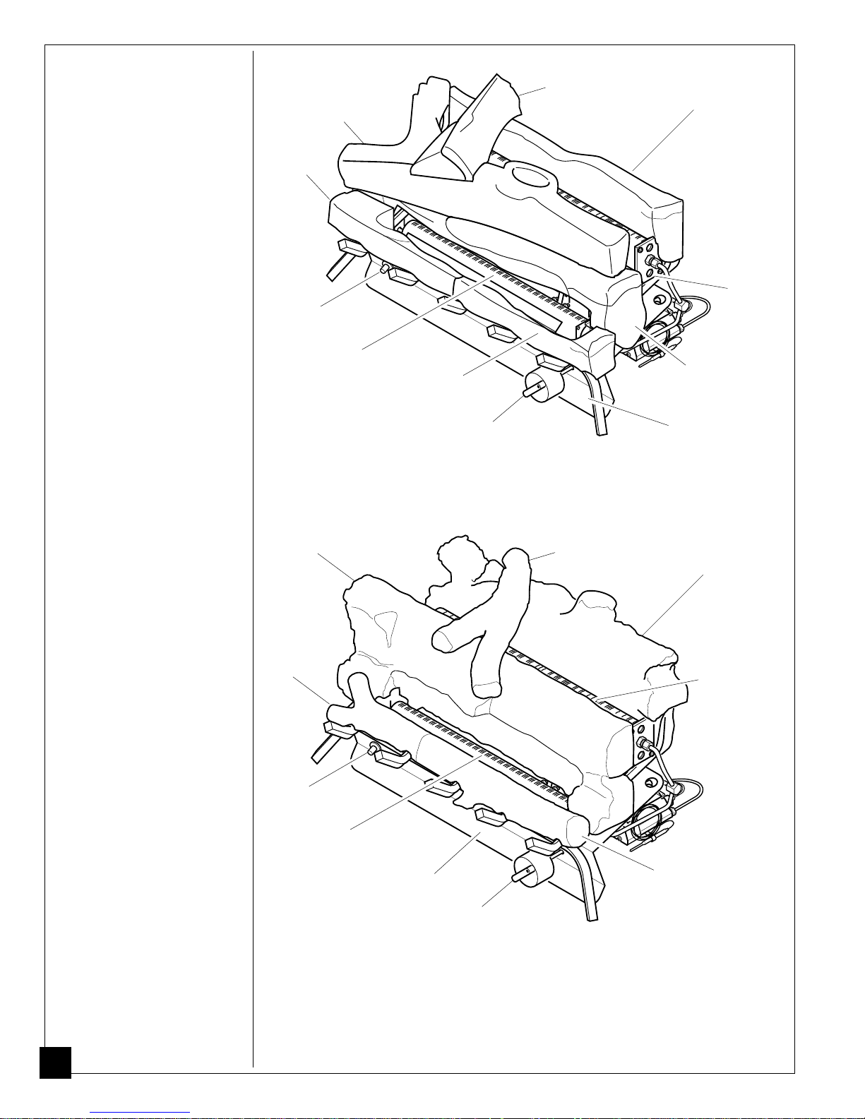
PRODUCT
IDENTIFICATION
Top Middle Log
Left
Front
Branch
Crossover Log
Rear Log
Piezo
Ignitor
Front Log
Left Front
Branch
Front
Burner
Right Front
Branch
Control Knob
Figure 1 - Split Oak Design Model
Crossover Log
Rear
Burner
Bottom
Middle
Log
Base Assembly
Rear Log
Rear Burner
Piezo
Ignitor
4
Front
Burner
Base Assembly
Control Knob
Figure 2 - Standard Oak Design Model
Right
Front
Branch
102653
LOCAL CODES
Install and use heater with care. Follow all local codes. In the absence of local
codes, use the latest edition of The National Fuel Gas Code ANSI Z223, also
known as NFPA 54*.
*Available from:
American National Standards Institute, Inc.
1430 Broadway
New York, NY 10018
National Fire Protection Association, Inc.
Batterymarch Park
Quincy, MA 02269
Note:
Where listed vented decorative logs are required, thermostat operation is
not permitted.
UNPACKING
PRODUCT
FEATURES
1. Remove logs and heater base assembly from carton.
heater base assembly by burners. This could damage heater. Always handle
base assembly by grate.
2. Remove all protective packaging applied to logs and heater for shipment.
3. Check all items for any shipping damage. If damaged, promptly inform dealer
where you bought heater.
Operation
This heater is clean burning. It requires no outside venting. There is no heat loss out
a vent or up a chimney. Heat is generated by both realistic flames and glowing coals.
This heater is designed for vent-free operation with flue damper closed. State and local
codes in some areas prohibit the use of vent-free heaters. You can operate heater as a
vented product by opening flue damper.
Safety Device
This heater has a pilot with an Oxygen Depletion Sensor Shutoff System (ODS).
The ODS/pilot is a required feature for vent-free room heaters. The ODS/pilot
shuts off the heater if there is not enough fresh air.
Piezo Ignition System
This heater has a piezo ignitor. This system requires no matches, batteries, or other
sources to light heater.
Note:
Do not pick up
AIR FOR
COMBUSTION
AND
VENTILATION
Today’s homes are built more energy efficient than ever. New materials, increased
insulation, and new construction methods help reduce heat loss in homes. Home
owners weather strip and caulk around windows and doors to keep the cold air out
and the warm air in. During heating months, home owners want their homes as
airtight as possible.
While it is good to make your home energy efficient, your home needs to breathe.
Fresh air must enter your home. All fuel-burning appliances need fresh air for
proper combustion and ventilation.
Exhaust fans, fireplaces, clothes dryers, and fuel burning appliances draw air from
the house to operate. You must provide adequate fresh air for these appliances.
This will insure proper venting of vented fuel-burning appliances.
102653
W ARNING
This heater shall not be installed in a confined space unless
provisions are provided for adequate combustion and ventilation
air. Read the following instructions to insure proper fresh air for
this and other fuel-burning appliances in your home.
Continued
5

AIR FOR
COMBUSTION
AND
VENTILATION
Continued
PROVIDING ADEQUATE VENTILATION
The following is exerpts from National Fuel Gas Code. NFPA 54/ANSI Z223.1,
Section 5.3, Air for Combustion and Ventilation.
All spaces in homes fall into one of the three following ventilation classifications:
1. Unusually Tight Contruction; 2. Unconfined Space; 3. Confined Space.
The information on pages 5 through 8 will help you classify your space and provide
adequate ventilation.
Unusually Tight Construction
The air that leaks around doors and windows may provide enough fresh air for
combustion and ventilation. However, in buildings of unusually tight construction,
you must provide additional fresh air.
Unusually tight construction is defined as construction where:
a. walls and ceilings exposed to the outside atmosphere have a continu-
ous water vapor retarder with a rating of one perm or less with openings gasketed or sealed
b. weather stripping has been added on openable windows and doors
and
c. caulking or sealants are applied to areas such as joints around window
and door frames, between sole plates and floors, between wall-ceiling
joints, between wall panels, at penetrations for plumbing, electrical, and
gas lines, and at other openings.
If your home meets all of the three criteria above, you must provide additional fresh air. See
If your home does not meet all of the three criteria above, proceed to page 6.
Ventilation Air From Outdoors
and
, page 8
.
Unconfined Space
The National Fuel Gas Code, ANSIZ223.1, 1992, Section 5.3 defines uncon-
fined space as having a minimum air volume of 50 cubic feet (127 cubic cm)
for each 1000 Btu/Hr input rating of all appliances in the space (cubic feet
equals length x width x height of space). Include adjoining rooms only if there
are doorless passageways or ventilation grills between the rooms.
Confined Space
The National Fuel Gas Code, ANSIZ223.1, 1992, Section 5.3 defines confined
space as having an air volume of less than 50 cubic feet (127 cubic cm) for each
1000 Btu/Hr input rating of all appliances in the space (cubic feet equals length
x width x height of space). Include adjoining rooms only if there are doorless
passageways or ventilation grills between the rooms.
6
102653

AIR FOR
COMBUSTION
AND
VENTILATION
Continued
DETERMINING AIR FLOW FOR HEATER LOCATION
Determining if You Have a Confined or Unconfined Space
Use this work sheet to determine if you have a confined or unconfined space.
Space: Includes the room in which you will install heater plus any adjoining rooms with
doorless passageways or ventilation grills between the rooms.
1. Determine the volume of the space (length x width x height).
Length x Width x Height = ___________________ cu. ft. (volume of space)
Example:
If additional ventilation to adjoining room is supplied with grills or openings, add the
volume of these rooms to the total volume of the space.
2. Divide the space volume by 50 cubic feet to determine the maximum Btu/Hr the space
can support.
____________ (volume of space) ÷ 50 cu. ft. = (Maximum Btu/Hr
the space can support)
Example:
Btu/Hr the space can support)
3. Add the Btu/Hr of all fuel burning appliances in the space.
Example:
* Do not include direct-vent gas appliances. Direct-vent draws combustion air from the
outdoors and vents to the outdoors.
4. Compare the maximum Btu/Hr the space can support with the actual amount of Btu/Hr
used.
_________________ Btu/Hr (maximum the space can support)
_________________ Btu/Hr (actual amount of Btu/Hr used)
Example:
The space in the above example is a confined space because the actual Btu/Hr used is more
than the maximum Btu/Hr the space can support. You must provide additional fresh air.
Your options are as follows:
A. Rework worksheet, adding the space of an adjoining room. If the extra space provides
an unconfined space, remove door to adjoining room or add ventilation grills between
rooms. See Ventilation Air From Inside Building, page 8.
B. Vent room directly to the outdoors. See Ventilation Air From Outdoors, page 8.
C. Install a lower Btu/Hr heater, if lower Btu/Hr size makes room unconfined.
If the actual Btu/Hr used is less than the maximum Btu/Hr the space can support, the space
is an unconfined space. You will need no additional fresh air ventilation.
Space size 20 ft. (length) x 16 ft. (width) x 8 ft. (ceiling height) =
2560 cu. ft. (volume of space)
2560 cu. ft. (volume of space) ÷ 50 cu. ft. = 51.2 or 51,200 (maximum
Vent-free heater ___________________ Btu/Hr
Gas water heater* ___________________ Btu/Hr
Gas furnace ___________________ Btu/Hr
Vented gas heater ___________________ Btu/Hr
Gas fireplace logs ___________________ Btu/Hr
Other gas appliances* + ___________________ Btu/Hr
Total = ___________________ Btu/Hr
Gas water heater 40,000 Btu/Hr
Vent-free heater + 33,000 Btu/Hr
Total = 73,000 Btu/Hr
51,200 Btu/Hr (maximum the space can support)
73,000 Btu/Hr (actual amount of Btu/Hr used)
102653
Continued
7
AIR FOR
COMBUSTION
AND
VENTILATION
Continued
W ARNING
If the area in which the heater may be operated is smaller than
that defined as an unconfined space, provide adequate combustion and ventilation air by one of the methods described in the
National Fuel Gas Code, ANSI Z223.1, 1992, Section 5.3.
VENTILATION AIR
Ventilation Air From Inside Building
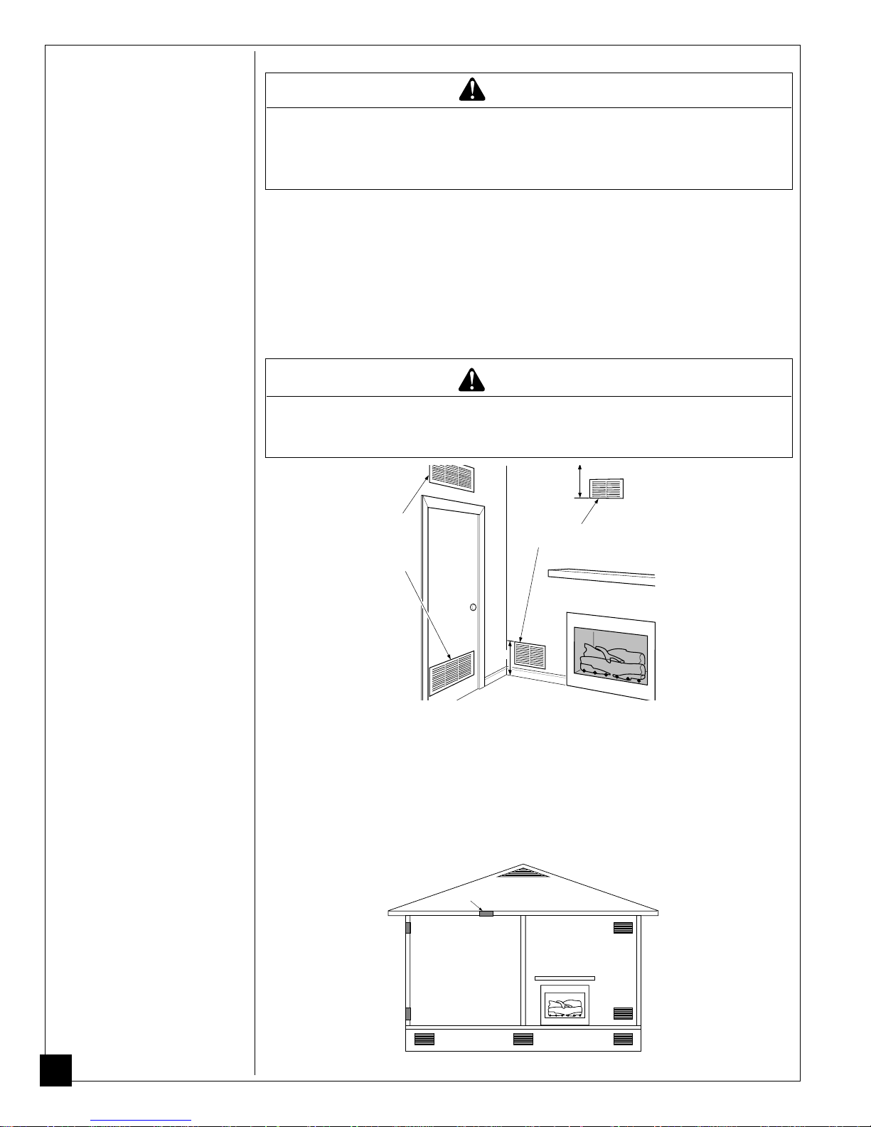
This fresh air would come from an adjoining unconfined space. When ventilating to an
adjoining unconfined space, you must provide two permanent openings: one within 12" of the
ceiling and one within 12" of the floor on the wall connecting the two spaces (see options 1
and 2, Figure 3). You can also remove door into adjoining room (see option 3, Figure 3).
Follow the National Fuel Gas Code NFPA 54/ANSI Z223.1, Section 5.3, Air for Combustion
and Ventilation for required size of ventilation grills or ducts.
W ARNING
Rework worksheet, adding the space of the adjoining unconfined
space.
appliances in both spaces.
The combined spaces must have enough fresh air to supply all
12"
Ventilation
Grills
Into Adjoining
Room,
Option 1
Or
Remove
Door into
Adjoining
Room,
Option
3
Ventilation Grills
Into Adjoining Room,
Option 2
12"
Figure 3 - Ventilation Air from Inside Building
Ventilation Air From Outdoors
Provide extra fresh air by using ventilation grills or ducts. You must provide two permanent openings: one within 12" of the ceiling and one within 12" of the floor. Connect these
items directly to the outdoors or spaces open to the outdoors. These spaces include attics
and crawl spaces.
IMPORTANT:
thermostat-controlled power vent. Heated air entering the attic will activate the power
vent.
Do not provide openings for inlet or outlet air into attic if attic has a
Ventilated
Attic
To Attic
Outlet
Air
Outlet
Air
8
To
Crawl
Inlet
Air
Inlet Air
Ventilated
Crawl Space
Space
Figure 4 - Ventilation Air from Outdoors
102653
INSTALLING
NOTICE
A qualified service person must install heater. Follow all local codes.
NOTICE
State or local codes may only allow operation of this appliance in a
vented configuration. Check your state or local codes.
W ARNING
Before installing in a solid fuel burning fireplace, the chimney flue
and firebox must be cleaned of soot, creosote, ashes and loose paint
by a qualified chimney cleaner. Creosote will ignite if highly heated.
Inspect chimney flue for damage. If damaged, operate heater with
flue damper closed.
W ARNING
Seal any fresh air vents or ash clean-out doors located on floor or wall
of fireplace. If not, drafting may cause pilot outage or sooting. Use a
heat-resistant sealant. Do not seal chimney flue damper.
W ARNING
Never install the heater
• in a bedroom or bathroom
• in a recreational vehicle
• where curtains, furniture, clothing, or other flammable objects are
less than 36 inches from the front, top, or sides of the heater
• in high traffic areas
• in windy or drafty areas
CAUTION
This heater creates warm air currents. These currents move heat
to wall surfaces next to heater. Installing heater next to vinyl or
cloth wall coverings or operating heater where impurities in the air
(such as tobacco smoke) exist, may discolor walls.
IMPORTANT:
cial, installing heater in rooms without enough ventilation air may cause mildew to
form from too much moisture. See Air for Combustion and Ventilation, pages 5
through 8.
Vent-free heaters add moisture to the air. Although this is benefi-
CHECK GAS TYPE
Use only propane gas. If your gas supply is not propane, do not install heater. Call
dealer where you bought heater for proper type heater.
102653
Continued
9

INSTALLING
INSTALLATION AND CLEARANCES (Vent-Free Operation Only)
Continued
WARNING
Maintain the minimum clearances. If you can, provide greater clearances from floor, ceiling, and adjoining wall.
MINIMUM FIREPLACE CLEARANCE
TO COMBUSTIBLE MATERIALS
Log Size Side Wall Ceiling Floor
18", 24", 30" 16" 42" 5"
LOG SIZING REQUIREMENTS
Log Minimum Firebox Size
Size Height Depth Front Width Rear Width
18" 17" 14" 20" 14"
24" 17" 14" 26" 18"
30" 17" 14" 32" 22"
Carefully follow the instructions below. This will ensure safe installation into a
masonry or U.L. listed manufactured fireplace.
Minimum Wall and Ceiling Clearances (see Figure 5)
A. Clearances from the side of the fireplace opening to any combustible wall
should not be less than 16 inches.
B. Clearances from the top of the fireplace opening to the ceiling should not be
less than 42 inches.
42"
16"
10
Figure 5 - Minimum Clearance to Wall and Ceiling
102653
INSTALLING
NOTICE
Continued
Manual control heaters may be used as a vented
product. If so, you must always run heater with
chimney flue damper open. If running heater with
damper open, non-combustible material above
fireplace opening is not needed. Go to
Installing
Damper Clamp Accessory for Vented Operation,
page 14.
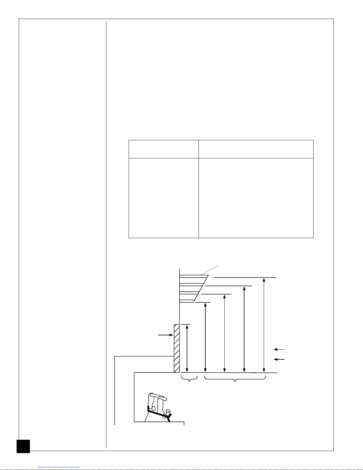
Minimum Non Combustible Material Clearances
If Not Using Mantel
Note:
If using a mantel, go to page 12. If not using a mantel, follow the informa-
tion on this page.
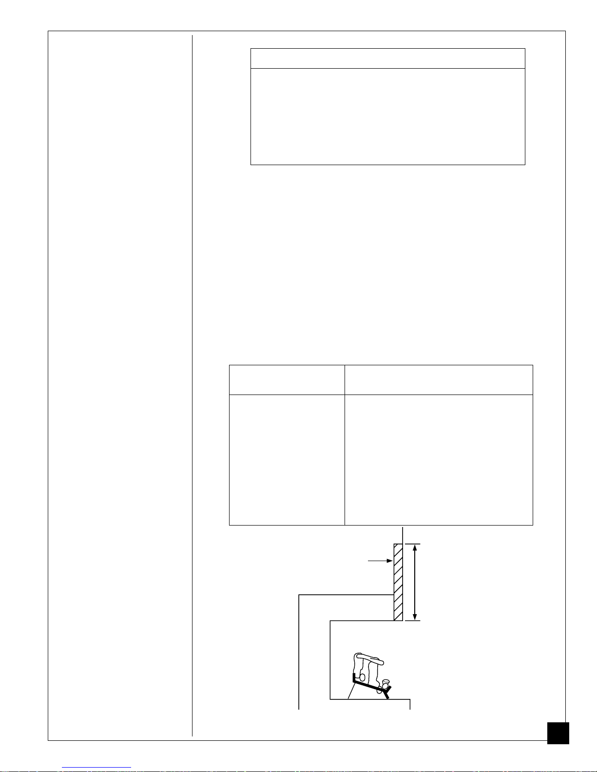
You must have non combustible material(s) above the fireplace opening. Non
combustible materials (such as slate, marble, tile, etc.) must be at least 1/2 inch
thick. With sheet metal, you must have non combustible material behind it. Non
combustible material must extend at least 8" up (for all models). If non combustible material is less than 12", you must install the fireplace hood accessory (24"
and 30" models only). See chart below and Figure 5 for minimum clearances.
IMPORTANT:
If you cannot meet these minimum clearances, you must operate
heater with chimney flue damper open. Go to Installing Damper Clamp Accessory
for Vented Operation, page 14.
Noncombustible Requirements for
Material Distance (A) Safe Installation
12" or more Noncombustible material OK.
Between 8" and 12" 24" or 30" Models: Install fireplace hood
accessory (GA6050 or GA6052, see
Accessories,
18" Model: Noncombustible material OK.
Less than 8" Noncombustible material must be
extended to at least 8". See
and 12",
material, you must operate heater with
flue damper open.
Heat Resistant
Material
page 35).
Between 8"
above. If you cannot extend
(A)
102653
Figure 6 - Heat Resistant Material (Slate, Marble, Tile, etc.) Above Fireplace
Continued
11
INSTALLING
Continued
Minimum Noncombustible Material Clearances
If Using Mantel
You must have noncombustible material(s) above the fireplace opening. Noncombustible materials (such as slate, marble, tile, etc.) must be at least 1/2 inch thick.
With sheet metal, you must have noncombustible material behind it. Noncombustible material must extend at least 8 inches up (for all models). If noncombustible
material is less than 12", you must install the fireplace hood accessory (24" and 30"
models only). Even if noncombustible material is more than 12", you may need the
hood accessory to deflect heat away from your mantel shelf. See chart below and
Figures 7 and 8 for minimum clearances.
IMPORTANT:
If you cannot meet these minimum clearances, you must operate
heater with chimney flue damper open. Go to Installing Damper Clamp Accessory
for Vented Operation, page 14.
Noncombustible Requirements for
Material Distance (A) Safe Installation
12" or more Noncombustible material OK.
Between 8" and 12" 24" or 30" Models: Install fireplace hood
accessory (GA6050 or GA6052, see
Accessories,
page 35).
18" Model: Noncombustible material OK.
Less than 8" Noncombustible material must be
extended to at least 8". See
and 12",
above. If you cannot extend
Between 8"
material, you must operate heater with
flue damper open.
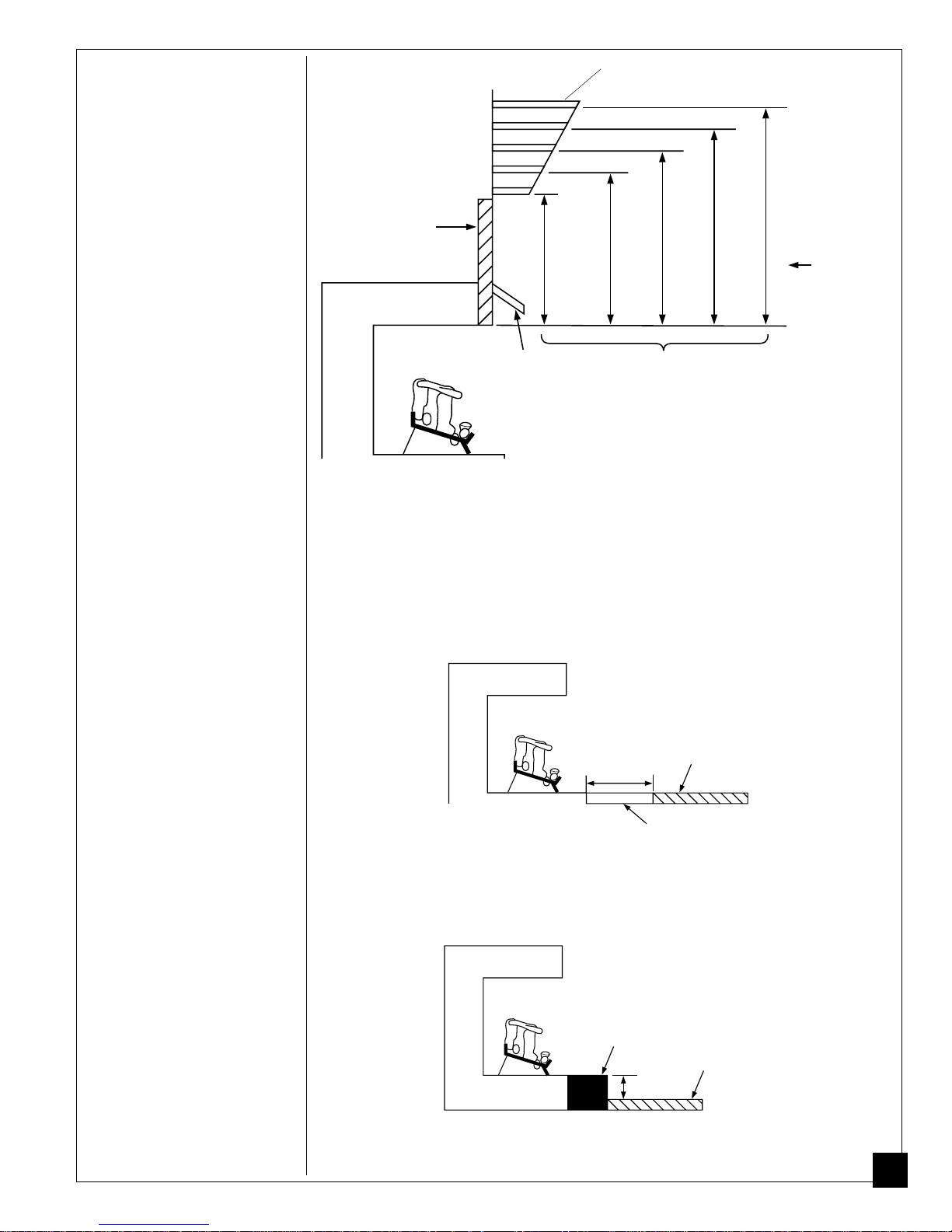
Mantel Clearances
If you meet minimum clearance between mantel shelf and top of fireplace opening,
a hood is not required (see Figure 7).
Mantel Shelf
10"
8"
6"
2
1
/2
"
Underside of
Mantel Shelf
If above minimum clearances are not met, you must have a hood. Follow
12
minimum clearances shown in Figure 8 on page 13 when using hood.
Minimum NonCombustible
Material
Figure 7 - Minimum Mantel Clearances Without Using Hood
(A)
12"
8"
Minimum NonCombustible
Material Height
20"
14"
1
24
/2
"
27
3
/4
"
16
Distances to
Underside of
Mantel
18
All minimum
distances are
in inches
1
/2
"
30"
1
/2
"
20"
Log Set
24"/30" Models
18" Model
Top of Fireplace
Opening
102653
Mantel Shelf
INSTALLING
Continued
Minimum NonCombustible
Material
12"
10"
8"
6"
1
"
/2
2
8"
Min.
Hood
(GA6050, GA6052)
12" 15" 18"
Distances to
Underside of
Mantel
Underside of
Mantel Shelf
All minimum
distances are
in inches
Log Sets
18", 24",
20"
& 30" Models
Top of Fireplace
Opening
Figure 8 - Minimum Mantel Clearances When Using Hood
If your installation does not meet the above minimum clearances, you must:
• operate the logs only with the flue damper open, OR
• raise the mantel to an acceptable height, OR
• remove the mantel.
Floor Clearances
A. If installing appliance on the floor level, you must maintain the minimum
distance of 14" to combustibles (see Figure 9).
Combustible
14"
Min.
Material
Non-Combustible
Material
Figure 9 - Minimum Fireplace Clearances If Installed at Floor Level
B. If combustible materials are less than 14" to the fireplace, you must install
appliance at least 5" above the combustible flooring (see Figure 10).
Hearth
5"
Min.
Combustible
Material
102653
Figure 10 - Minimum Fireplace Clearances Above Combustible Flooring
Continued
13
INSTALLING
Continued
INSTALLING DAMPER CLAMP ACCESSORY FOR
VENTED OPERATION
Note:
When used as a vented heater, appliance must be installed only in a solid-
fuel burning fireplace with a working flue and constructed of non combustible
material.
If your heater is a manually controlled model, you may use this heater as a vented
product. There are three reasons for operating your heater in the vented mode.
1. The fireplace does not meet the clearance to combustibles requirements for
vent-free operation.
2. State or local codes do not permit vent-free operation.
3. You prefer vented operation.
If reasons number 1 or 2 above apply to you, you must permanently open chimney flue
damper. You must install the damper clamp accessory (to order, see Accessories, page
35). This will insure vented operation (see Figure 11). The damper clamp will keep
damper open. Installation instructions are included with clamp accessory.
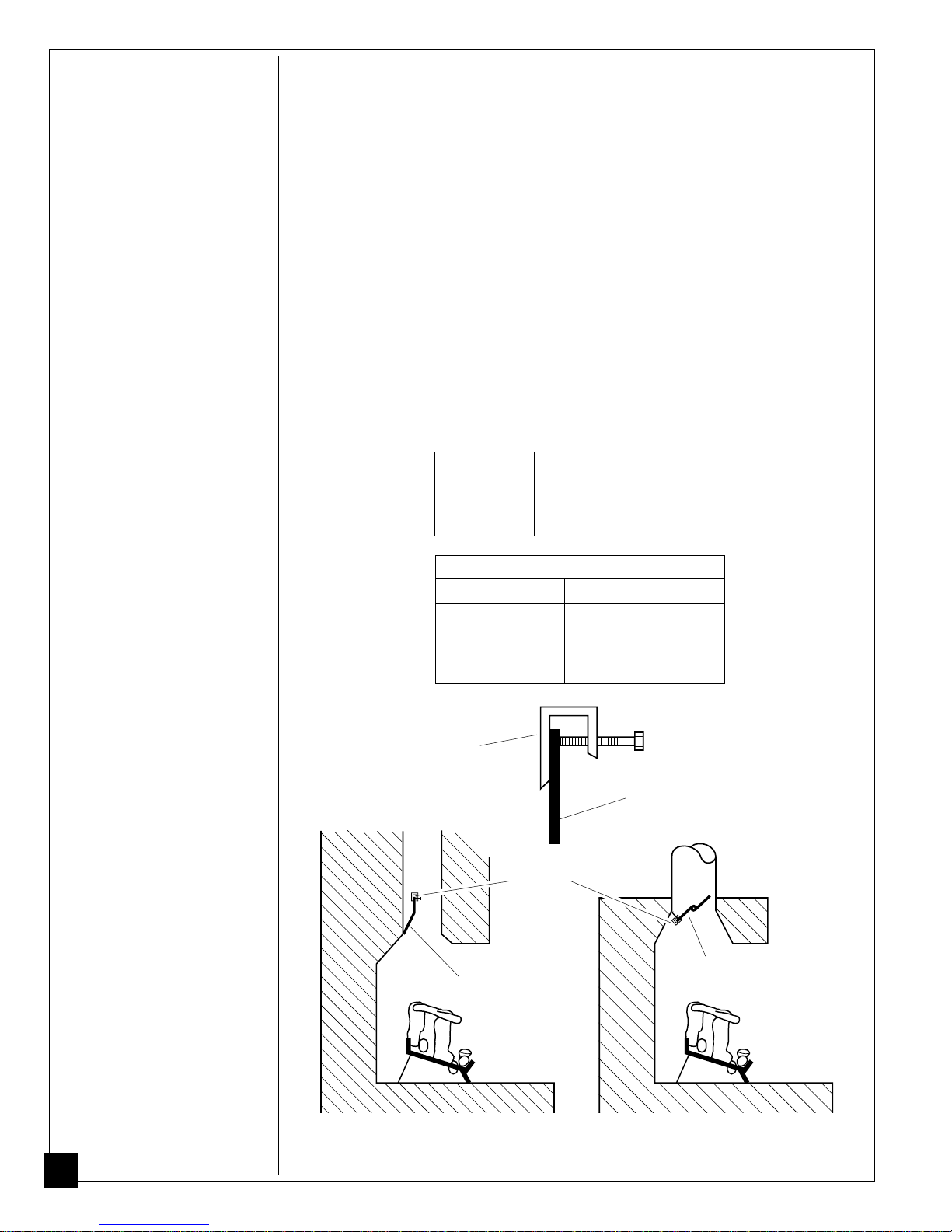
See chart below for minimum permanent flue opening you must provide. Attach
damper clamp so the minimum permanent flue opening will be maintained at all times.
Chimney Minimum Permanent
Height (ft.) Flue Opening (sq. ins.)
6' to 15' 39 sq. inches
15' to 30' 29 sq. inches
Area of Various Standard Round Flues
Diameter (ins.) Area (sq. ins.)
5" 20 sq. inches
6" 29 sq. inches
7" 39 sq. inches
8" 51 sq. inches
Damper
Clamp
Damper
Damper
Clamp
Damper
Damper
14
Masonry Fireplace
Figure 11 - Attaching Damper Clamp
Manufactured Fireplace
102653
 Loading...