

Page 1
®
B-VENT DECORATIVE GAS FIREPLACE
OWNER’S OPERATION AND INSTALLATION MANUAL
®
VGL450N (NATURAL) AND VGL450P (PROPANE/LP)
FOR YOUR SAFETY
— Do not store or use gasoline or any other flam-
mable vapors or liquids in the vicinity of this or
any other appliance.
— Due to high temperatures, the appliance should
be located out of traffic and away from furniture
and draperies.
— Do not place clothing or other flammable mate-
rials on or near the appliance.
— NEVER leave children unattended when a fire is
burning in the appliance.
— WHAT TO DO IF YOU SMELL GAS :
• Do not try to light any appliance.
• Do not touch any electrical switch;
• Do not use any phone in your building.
• Immediately call your gas supplier from a
neighbor’s phone. Follow the gas supplier’s
instructions.
• If you cannot reach your gas supplier, call the
fire department.
SAVE THIS BOOK
This book is valuable. In addition to instructing
you on how to install and maintain your appliance, it also contains information that will
enable you to obtain replacement parts or
optional accessory items when needed. Keep
it with your other important papers.
WARNING: Improper installation,
adjustment, alteration, service or
maintenance can cause injury or
property damage. Refer to this
manual. For assistance or additional
information consult a qualified installer, service agency, or the gas
supplier.
WARNING: THE DECORATIVE GAS APPLIANCE SERIES IS INTENDED FOR USE WITH
NATURAL OR PROPANE GAS ONLY ! (DEPENDING ON THE TYPE OF GAS YOUR
PARTICULAR MODEL IS APPROVED FOR).
DO NOT ATTEMPT TO BURN ANY SOLID
FUELS IN THESE APPLIANCES.
CHECK LOCAL CODES PRIOR TO INSTALLATION
This appliance may be installed in an aftermarket* manufactured (mobile) home, where not prohibited by state
or local codes.
*Aftermarket: Completion of sale, not for purpose of resale, from the manufacturer.
Save this manual for future reference.
Page 2
VGL450 Series
J
TH
TP
TP
TH
IN
PILOT ADJ
ON OFF
P
I
L
O
T
R
O
B
E
R
T
S
H
A
W
®
VENTED TYPE DECORATIVE APPLIANCE
33"
12
4
29 1/2"
4" DIA.
19"
1
/2"
Nailing
Flange
4
10"
14"
5/8"
HEARTH
DIMENSIONS
2 7/8"
2"
17"
24"
36"
3/4"
Spacers
1
2
/2"
23
3
25
/8"
3
/4"
1
/2"
21 7/8"
7
3 Sides
3
/4"
1
/2"
24"
1"
1 1/4"
32"
33 5/8"
AGA and CGA Rating Labels
Located Behind Access Panel
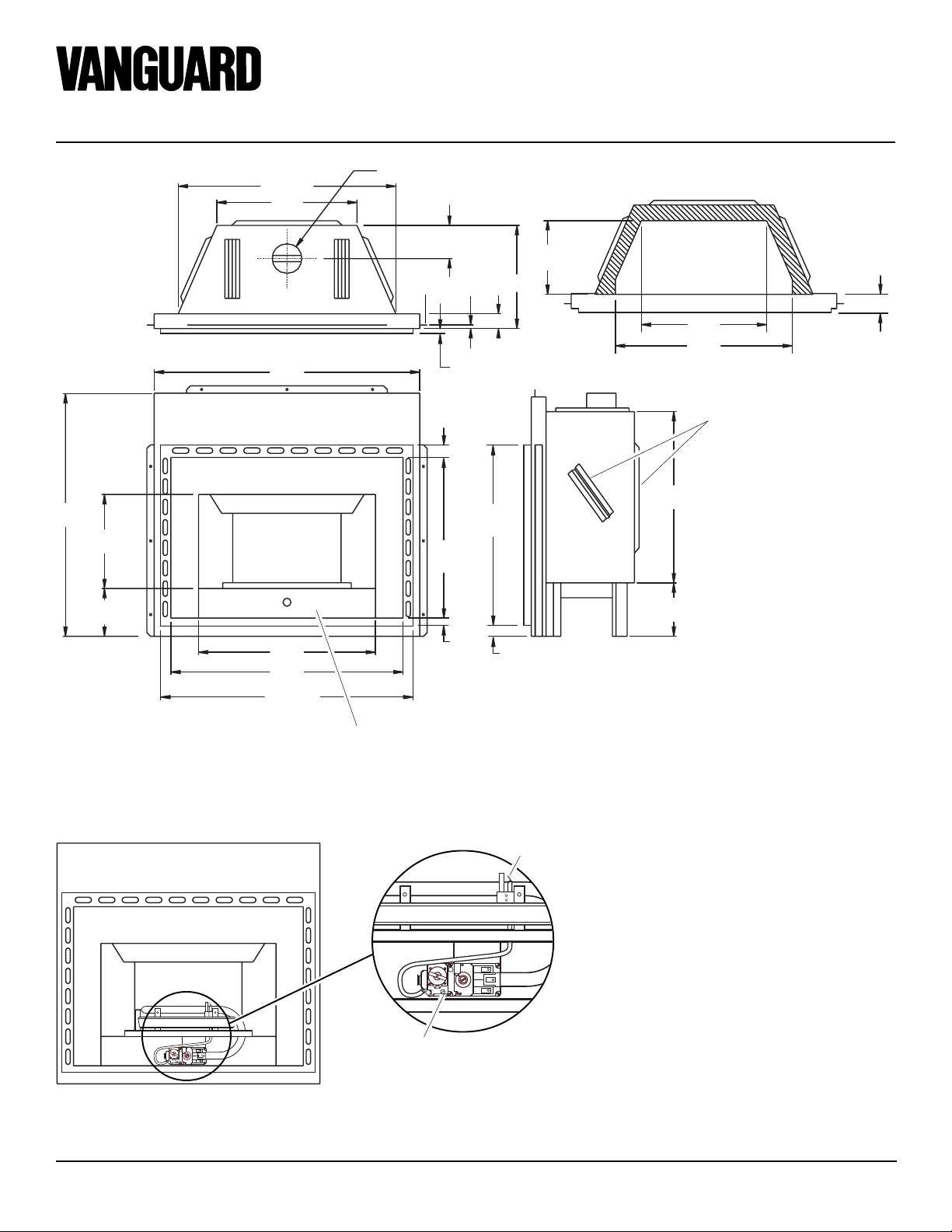
Figure 1 - Appliance Dimensions
Note:
All dimensions in this installation manual are in inches unless otherwise specified.
Pilot Assembly
ON OFF
W
A
H
IN
TH
S
T
TP
R
P
T
I
L
O
E
B
TH
TP
O
R
PILOT ADJ
J
Control Valve
Figure 2 - Location of Pilot Assembly and Control Valve (Access Panel and Logs
Removed for Clarity)
2
105704
Page 3
OWNER’S MANUAL
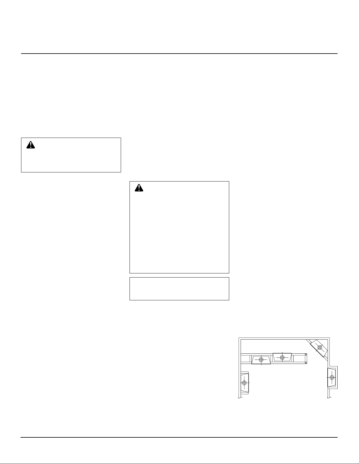
INTERNAL WALL
INSTALLATION
CORNER
INSTALLATION
FULL
PROJECTION
INSTALLATION
FLUSH
INSTALLATION
INTRODUCTION
Model VGL450 series is a radiant heat decorative gas appliance that uses a millivolt gas
control valve and a pilot ignition system.
This appliance requires a 4" B-1 type venting system.
4" B-1 type vent NOT supplied by DESA.
Check with your "B" vent instructions for
installation guidelines.
WARNING: This gas appliance must not be connected to a
chimney flue servicing a solid
fuel burning appliance.
• Model VGL450N uses N ATURAL GAS
ONL Y.
• Model VGL450P uses PROPANE GAS
ONLY.
If you have any doubts as to which gas your
particular unit is approved and tested for,
please check the AGA/CGA rating plate
located behind the access panel (Figure 1,
page 2).
BEFORE YOU BEGIN
Before beginning the installation of your
appliance, read these instructions through
completely.
This DESA appliance and its approved components are safe when installed according to
this installation manual and are operated as
recommended by DESA. Unless you use
DESA approved components tested for this
appliance, YOU MAY CAUSE A FIRE
HAZARD!
The DESA warranty will be voided by, and
DESA disclaims any responsibility for the
following actions :
A) Modification of the appliance or any of
the components manufactured by
DESA unless otherwise permitted in
writing by DESA.
B) Use of any component part not ap-
proved by DESA in combination with
this DESA appliance.
C) Installation and/or operation in a man-
ner other than instructed in this manual.
D) The burning of an ything other than the
type of gas approved for use in this gas
appliance.
This appliance, when installed, must be
electrically grounded in accordance with
local codes or, in the absence of local codes,
with the National Electrical Code, ANSI/
NFPA 70 or the CSA C22.1 CANADIAN
ELECTRICAL CODE for Canada.
The installation must conform with local
codes or, in the absence of local codes, with
the National Fuel Gas Code ANSI Z223.1 or
with the current CAN/CGA-B149[.1 OR .2]
Installation Codes for Canada.
This appliance complies with ANS Z21.50-
1998 and CAN/CGA 2.22-M98 Standard as
a VENTED DECORATIVE GAS APPLIANCE and is tested and listed by the Ameri-
can Gas Association and Canadian Gas
Association.
CAUTION: Installation and repair should be done by a qualified service person. The appliance should be inspected before
use, and at least annually by a
qualified service person. More frequent cleaning may be required
due to excessive lint from carpeting, bedding material, pet hair,
etc. It is imperative that the control compartments, burners and
circulating air passageways of
the appliance be kept clean.
NOTICE: This appliance is not
intended to be used as a primary
source of heat.
SELECTING
LOCATION
To determine the safest and most efficient
location for your appliance, you must take
into consideration the following guidelines:
1. The location must allow for proper
clearances (see Clearances, page 4 ).
2. Consider a location where heat output
would not be affected by drafts, air conditioning ducts, windows or doors.
3. A location that avoids the cutting of
joists or roof rafters will make installation easier. Figure 3 sho ws a plan view
of a few common locations.
Flush installations are recommended
where living space is limited or at a premium, and since the space required to enclose the appliance would be located beyond an outside wall, this would also reduce
the cutting of joists, roof rafters and such.
Check local codes for any restrictions.
Projected installations can extend any
distance into the room. A projection may be
ideal for a new addition on an existing,
finished wall.
Corner installations make use of space
that may not normally be used and provides
a wider and more efficient range for radiant
heat transference.
Internal wall installations provide a discreet option for room separation and can
also be ideal as an addition to an existing
wall.
Also, in selecting a location, the following
precautions must be observed:
1. Do not connect this appliance to a
chimney system used for a solid fuel
burning fireplace.
2. Install in an area providing ventilation
and adequate combustion air.
3. Due to high temperatures, the appliance
should be located out of traffic and
away from furniture and draperies.
4. NEVER obstruct the front opening of
the appliance or the flow of combustion and ventilation air. Keep control
compartments accessible.
5. Do not locate in the vicinity where
gasoline or other flammable liquids
may be stored. The appliance area must
be kept clear and free from these combustible materials.
Figure 3 - Possible Locations for Installing
Appliance
105704
3
Page 4
VGL450 Series
23 5/8"
MINIMUM
33 3/8"
MINIMUM TO
FRAMING
10 3/8"
MIN.
DRYWALL
36 1/4"
14" MIN.
36 1/4"
MIN.
33 1/4"
MIN.
*
14" MIN.
36 1/4"
MIN.
33 1/4"
MIN.
®
VENTED TYPE DECORATIVE APPLIANCE
PRE-INSTALLATION
PREPARATION
CLEARANCES
Minimum clearances to combustibles are:
• Back and sides
of outer surround:.....................0" min.
• Drywall to sides
of front face:.............................0" min.
• "B" V ent surfaces: ....................1" min.
• Ceiling to opening:.................30" min.
• Floor: ........................................ 0" min.
• Adjacent side wall:..................18" min
0" Clearance
Nail to Stud
or Header
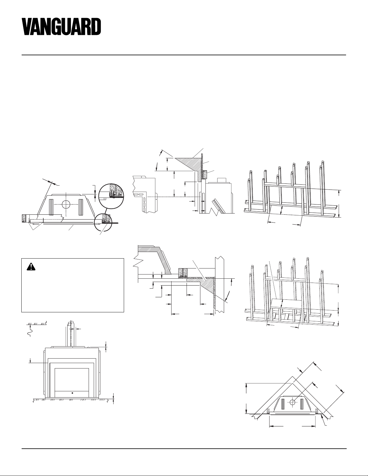
Figure 4 - Minimum Clearances (Top View)
Front
Face
Drywall
MANTEL CLEARANCES
Woodwork, such as wood trims, mantels,
and other combustible material, must not be
placed within 7 inches of the appliance's
opening. Combustible material projecting
more than 1 1/2 inches from the appliance's
front face must not be placed less than 12
inches from the opening of the appliance
(ref. NFPA Standard 211 Section 7-3.3.3.).
Figures 6 and 7 show limits on mantel
locations.
Combustible
33°
6" Nom.
Within
12"
7" Min.
3" Nom.
1 1/2"
Max.
Figure 6 - Mantel Clearances - Side View
(Cross Section)
Combustible
Material May
Be Used
Material
Drywall
Header
FRAMING
Typical framing is shown in Figures 8
through 10, depending on your particular
installation.
If the appliance is to be installed directly on
carpeting, tile (other than ceramic), or any
combustible material other than wood flooring, the appliance must be installed upon a
metal or wood panel extending the full width
and depth of the appliance.
If a raised platform is to be constructed,
ceiling clearance must be maintained (see
Clearances).
Figure 8 - Rough Opening for Installing in
Wall
Platform Must Be Solid, Flat, and Fully
Supported
CAUTION : Do not block required air spaces with insulation
or any other material.
Do not obstruct effective opening of appliance with any type of
facing material.
1" Min. Clearance To
“B” Vents Outer Pipe
30" Minimum
Clearance
From Top Of
Opening T o
Ceiling
Figure 5 - Minimum Clearances (Front
View)
0" Clearance
To Top Of Spacer
0" Clearance
To Floor
1 1/2"
MAX.
3"
NOM.
6" MIN.
WITHIN 12"
18" MIN. TO
ADJACENT WALL
33°
Figure 7 - Mantel Clearances - Top View
(Cross Section)
4
*As Required By Design, As Long As
Ceiling Clearance Is Maintained
Figure 9 - Rough Opening for Installing
on Raised Platform
Figure 10 - Rough Opening for Corner
Installation
105704
Page 5
OWNER’S MANUAL
PRE-INSTALLATION
PREPARATION
Continued
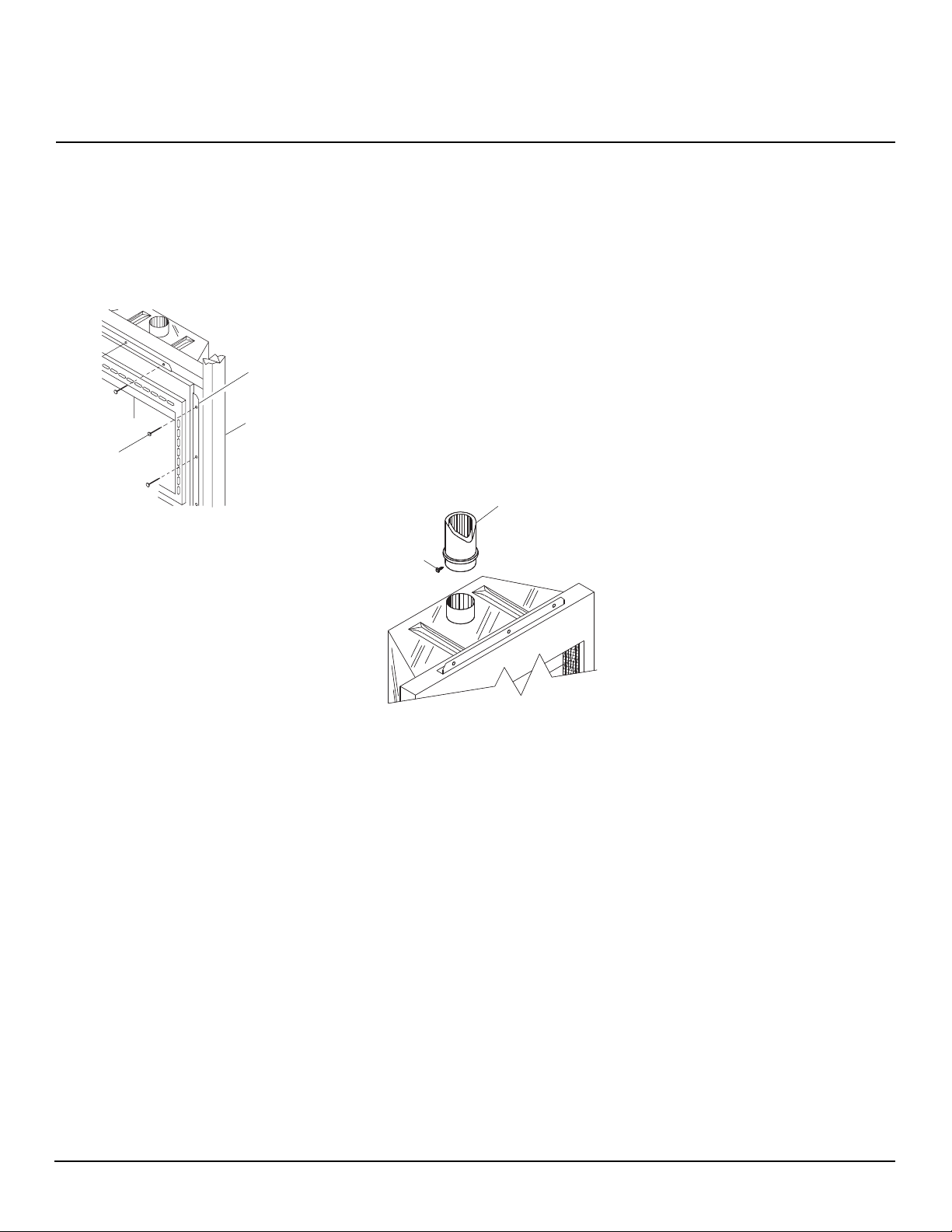
Proceed to secure appliance to prepared
framing at nailing flanges located at the
sides of the appliance as shown in Figure 11.
Nailing
Flanges
Framing
Nails
Figure 11 - Attaching Fireplace to Wall
Studs
VENTING
INSTALLATION
A 4" B-1 Type Gas Vent Pipe is a double
wall, unitized venting system (not supplied)
which must be installed during the rough
framing of the appliance. Any B-1 Type gas
vent system may be used for proper venting
as long as it is installed per the manufacturer's
recommendations.
This appliance has been supplied with a 4"
dia. starting collar for a snug fit. Slide B-1
vent pipe over starter pipe until fully seated.
Fasten this first section of "B" vent pipe by
running a 3/4" long sheet metal screw
through outer wall of pipe until secure. (see
Figure 12).
Double Wall B-1
Secure B-Vent
to Starter
Collar Using
3/4" Long
Sheet Metal
Screw
Type Vent
(Not Supplied)
The B-1 vent pipe must be properly terminated per manufacturer's instructions.
Check with your B-1 Vent installation instructions regarding multiple venting into a
common flue.
IMPORTANT:
minate in an attic space.
Minimum height for complete system (vent
termination and appliance) is 12 feet.
Maximum horizontal run of B-1 type vent
pipe can be no greater than 75% of total
vertical height of the vent.
Vent pipe MUST NOT ter-
Figure 12 - Securing “B” Vent to Starter
Collar
105704
5
Page 6

VGL450 Series
®
VENTED TYPE DECORATIVE APPLIANCE
INSTALLATION
WALL SWITCH
INSTALLATION
1. Remove access panel from lower front
face.
2. Connect the millivolt wires from terminals TH and TH/TP to wall switch
as shown in Figure 13 (both are sup-
The installation of a wall switch in this
plied).
appliance allows you to activate the gas
control valve without the use of normal
current.
CAUTION: Do not wire this
millivolt system wall switch to a
regular power supply.
Pilot
Thermopile
VGL450 SERIES MILLIVOLT
WIRING DIAGRAM
Gas Line
to Burner
Pilot Gas
Line
TH
CONTROL VALVE
Incoming
Main
Gas
Supply
(HEAT LIMIT
SWITCH)
Figure 13 - Wall Switch Wiring Diagram
Note:
If any of the original wire as supplied must be replaced, use 18 AWG TYPE CL2 (UL)
TP
TH/TP
USE ONLY CL2 THERMOSTAT WIRE
18 GA. RED/WHITE (PROVIDED)
OR EQUIVALENT
N.O. WALL SWITCH
105 C (25 ft. length MAXIMUM) or equivalent.
DO NOT
CONNECT
TO 120V
(SUPPLIED)
OPTIONAL WIRELESS HANDHELD REMOTE CONTROL
(GHRC) INSTALLATION
Note:
If using optional wireless hand-held
remote control, the wall switch is no longer
operational.
Installing Receiver
1. Remove access panel from lower front
face of firebox. Lift straight up on access panel until it stops. Pull bottom of
access panel forward, then down.
2. Disconnect wall switch wires from TH
and TH/TP terminals on control valve
(see Figure 13).
3. Install remote receiver unit onto mount-
ing bracket using the two plastic mounting clips (see Figure 14).
4. Connect wires to control valve. Con-
nect white wire to terminal TH. Connect red wire to terminal TH/TP.
5. Locate the battery clip mounted on the
back of the receiver (see Figure 15).
6. Slide 9-volt battery (not included)
through the clip.
line battery.
7. Attach the terminal wires to the battery
(see Figure 15).
8. Replace access panel. Place top of ac-
cess panel into opening and slide up.
Push bottom of access panel in and
slide down to install.
Receiver
Note:
Only use alka-
Plastic
Mounting
Clips
Mounting
Bracket
Figure 14 - Installing Remote Receiver
(Shown from Rear of Mounting Bracket)
9-Volt Battery
Battery
Clip
Terminal
Wires
Figure 15 - Installing Battery in Receiver
6
Receiver
105704
Page 7

OWNER’S MANUAL
INSTALLATION
Continued
Installing 9-Volt Battery in HandHeld Remote Control Unit
1. Remove battery cover on back of remote control unit.
2. Attach terminal wires to the battery
(not included). Place battery into the
battery housing.
line battery.
3. Replace battery cover onto remote control unit.
Battery
Terminal
Wires
9-Volt
Battery
Figure 16 - Installing Battery in HandHeld Remote Control Unit
Cover
Note:
Only use alka-
Remote
Control Unit
Battery
Housing
GAS SUPPLY TESTING
Note:
This section is intended as a guide for
qualified technicians installing gas to this
appliance.
Do not connect appliance before pressure
testing gas piping. Damage to gas valve may
result and an unsafe condition may be caused.
IMPORTANT:
vidual shut-off valve must be disconnected
The appliance and its indi-
A 1/8" NPT plugged tapping is provided on
the Gas Control Valve for a test gauge
connection immediately upstream of the
gas supply connection to the appliance (see
Figure 17).
Red Surface Indicates
For Propane Use Only
Gas Shut
Off Valve
Coupling
from the gas supply piping system during
any pressure testing of that system at test
pressures in excess of 1/2 psig (3.5 kPa).
The Gas Control Valve is secured to the
burner pan assembly underneath the front
ledge.
Flexible
Gas Line
DO NOT
KINK
Figure 17 - 1/8" Plugged Tapping Location
GAS RATINGS
TYPE OF GAS: NATURAL PROPANE/LP
MAX. INPUT
RATING (Btu/hr): 12,000 12,000
MANIFOLD
PRESSURE: 3.5 in. W.C. 10.0 in. W.C.
* MIN. SUPPLY
PRESSURE: 4.5 in. W.C. 7.0 in. W.C.
MAX. SUPPLY
PRESSURE: 10.5 in. W.C. 13.0 in. W.C.
P
I
L
O
T
IN
ON OFF
PILOT ADJ
Pilot
Adjustment
Cap
W
A
H
S
T
R
E
B
O
R
Air Shutter
TH
TP
TH
TP
1/8" NPT
Plugged
Tapping
105704
*For the purpose of input adjustment
Continued
7
Page 8

VGL450 Series
®
VENTED TYPE DECORATIVE APPLIANCE
INSTALLATION
Continued
GAS LINE HOOK-UP
NOTICE: Gas line hookup should
be done by your gas supplier or a
qualified service person.
WARNING: Before you pro-
ceed, make sure your gas supply
is OFF.
A manual shut-off valve must be included
within (6') six feet of the appliance’s gas
supply system. For your convenience, it
may be desirable to install the shut-off valve
outside the appliance's enclosure where it
can be accessed with a key through a wall as
shown in Figure 18.
Route an approved gas line towards the
appliance coming in from any direction (see
Figure 19).
A flexible gas line long enough to connect
the incoming approved gas line with the gas
control valve will be required, along with a
sediment trap.
The approximate location of the gas control
valve inlet is indicated in Figure 19.
Note:
Do NOT kink flexible gas line.
Before connecting the flexible gas line to
the gas control valve, a sediment trap must
be included between them. It must extend
down 3 inches beyond the center of the pipe
(See Figure 20).
Prepare incoming approved gas line with
teflon tape or pipe joint compound (Check
with local building codes).
CAUTION: Compounds used
on threaded joints of gas piping
shall be resistant to the action of
Liquefied Petroleum (LP or propane), and should be applied
lightly to ensure excess sealant
does not enter the gas line.
WARNING: All gas piping
and connections must be tested
for leaks after the installation is
completed.
After ensuring that the gas valve
is on, apply a soap and water
solution to all connections and
joints. If bubbles appear, leaks
can be detected and corrected.
Do not use an open flame for leak
testing and do not operate any
appliance if a leak is detected.
Complete your gas installation by connecting incoming gas line with flexible gas line.
Secure tightly with wrench but do not overtighten. Replace burner pan.
Figure 18 - Manual Shut-Off Valve
Installation
Note:
Incoming
Gas Line can
be Routed into
Appliance from
any Direction
6"
Approximate
Gas Valve
Inlet Location
Figure 19 - Routing Incoming Gas Line
4"
Figure 20 - Gas Connection
8
105704
Page 9

OWNER’S MANUAL
INSTALLATION
Continued
2. Place log #2 (large front log) in
groove on firebox floor in front of
burner with log texture facing up and
out (see Figure 22).
3. Place lava rock along sides and front
of inside of firebox bottom. It is not
necessary to use all of the lava rock
provided.
NOTICE: Do not put lava rock on
burner or under burner. Placing
lava rock on burner could cause
performance problems.
Figure 22 - Installing Log No. 2
OPERATING
FIREPLACE
FOR YOUR SAFETY
READ BEFORE
LIGHTING
WARNING: If you do not follow these instructions exactly, a
fire or explosion may result causing property damage, personal
injury or loss of life.
A. This appliance has a pilot which must
be lighted by hand. When lighting the
pilot, follow these instructions exactly .
B. BEFORE LIGHTING smell all
around the appliance area for gas. Be
sure to smell next to the floor because
some gas is heavier than air and will
settle on the floor.
WHAT TO DO IF YOU SMELL
GAS
• Do not try to light any appliance.
• Do not touch any electric switch; do
not use any phone in your building.
• Immediately call y our gas supplier
from a neighbor’s phone. Follow
the gas supplier’s instructions.
• If you cannot reach your gas supplier, call the fire department.
C. Use only your hand to push in or turn
the gas control knob. Ne ver use tools.
If the knob will not push in or turn
by hand, don’t try to repair it, call a
qualified service technician or gas
supplier. Force or attempted repair
may result in a fire or explosion.
D. Do not use this appliance if any part
has been under water. Immediately
call a qualified service technician to
inspect the appliance and to replace
any part of the control system and
any gas control which has been under water.
LIGHTING
INSTRUCTIONS
1. STOP! Read the safety information,
above.
2. Turn wall switch to the OFF position.
3. Tur n off all electric power to the appliance.
4. Remove control access panel.
5. Turn gas control knob clockwise
to the OFF position.
Clockwise
6. Wait five (5) minutes to clear out any
gas. If you smell gas, STOP! F ollow “B”
in the safety information. If you don’t
smell gas, go to the next step.
7. Find pilot. Follow metal tube from
gas control. The pilot is behind the
burner tube.
8. Tur n control knob counterclockwise
to the PILOT position.
C-clockwise
9. Push in the knob all the way and hold
in. Immediately light the pilot by
pressing the red ignitor button. Continue to hold the control knob in for
about (1) minute after the pilot is lit.
Release button and it will pop back
up. Pilot should remain lit. If it goes
out, repeat steps 5 through 9.
• If button does not pop up when
released, stop and immediately
call your service technician or gas
supplier .
• If the pilot will not stay lit after sev-
eral tries, turn the gas control knob
to “OFF” and call your service
technician or gas supplier.
10. Turn gas control knob counterclockwise
turned to “ON” only if the control
knob is popped out.
11. Replace control access panel.
12. Turn on all electric power to the appliance.
Position Indicator
TP
TP
TH
to “ON”. Knob can be
C-clockwise
R
O
TH
B
E
R
T
S
H
A
W
J
PILOT ADJ
O
L
I
T
P
IN
ON OFF
105704
Gas Control Knob
Figure 23 - Control Knob in the PILOT
position
9
Continued
Page 10

VGL450 Series
®
VENTED TYPE DECORATIVE APPLIANCE
OPERATING
FIREPLACE
Continued
TO TURN OFF GAS
TO APPLIANCE
1. Turn off the wall switch.
2. Tur n off all electric power to the appliance if service is to be performed.
3. Remove control access panel.
4. Turn gas control clockwise
to “OFF”. Do not force.
5. Replace control access panel.
OPTIONAL REMOTE
OPERATION
Note:
The GHRC receiver and handheld remote control kit must be purchased
separately (see Accessories & Replacement
Parts, page 14). Follow installation instructions on pages 6 and 7 of this manual.
1. After lighting, let pilot flame burn for
about one minute. T ur n control knob
to ON position. Adjust flame adjustment knob anywhere between HI
and LO. Slide the selector switch to
the REMOTE position.
burner may light if hand-held remote
ON button was on when selector
switch was last turned off. You can
now turn the burner on and off with
the hand-held remote control unit.
IMPORTANT:
lector switch in the REMOTE position when the pilot is not lit. This will
drain the battery.
IMPORTANT:
ON/OFF buttons on the hand-held
remote control unit for up to 3 seconds to assure proper operation.
2. Press the ON/OFF button to turn the
burner on and off. When turning
burner off, the pilot will remain lit.
IMPORTANT:
manually turn the control knob on
the heater to the OFF position.
Pilot Burner
Figure 24 - Pilot
Do not leave the se-
Be sure to press the
To turn the pilot off,
Thermopile
NOTE:
Clockwise
The
PILOT ASSEMBLY
ADJUSTMENT
The pilot assembly is factory preset for the
proper flame height. Alterations to these
settings may have occurred during shipping
and handling, if this is the case, some minor
readjustments may be necessary.
The pilot assembly is located behind the burner
tube on the right hand side. The thermopile
height should be at a distance of 3/8" to 1/2"
from the pilot flame (see Figure 25).
Thermopile
3/8" To 1/2"
Figure 25 - Correct Pilot Flame Pattern
Pilot
Burner
BURNER FLAME
ADJUSTMENT
The Air Shutter, located at the base of the
Main Burner Tube has been factory preset
to the proper air to gas ratio which results in
a long, blue flame (see Figure 26).
If readjustment is necessary, you can restore
proper flame setting by loosening the air
shutter screw and rotating the air shutter
until proper flame setting is achieved.
Tighten screw back (see Figure 17, page 7,
for air shutter location).
Closing the Air Shutter reduces the air to gas
mix resulting in a longer, yellow flame
which could cause sooting.
CORRECT
Long, Blue Flame
INCORRECT
CLOSE
SHUTTER
INCORRECT
OPEN
SHUTTER
Figure 26 - Burner Flame Patterns
Short, Sharp,
Blowing Flame
Long, Uneven,
Yellow Flame
OPERATING
GUIDELINES AND
MAINTENANCE
INSTRUCTIONS
Do not use this appliance if any part has
been under water. Immediately call a qualified service technician to inspect the appliance and to replace any part of the control
system and any gas control which has been
under water.
When lit for the first time, the appliance will
emit a slight odor for about an hour or two.
This is a normal occurrence which is due to
the "curing" of logs and "burn-in" of internal paints and lubricants used in the manufacturing process.
In cleaning, take care not to alter the settings
on the pilot assembly.
WARNING: Have a qualified
agency periodically inspect the
vent system at the start of each
heating season so as to be free of
any obstructions which may
hinder normal operation. Never
obstruct the flow of combustion
and ventilation air; keep the front
of the appliance clear of all obstacles and combustible materials such as gasoline or other flammable vapors or liquids. It is also
imperative that the control compartments, burners and circulating air passageways of the appliance be kept clean.
CAUTION: Keep control compartment, logs, burners, and area
surrounding the logs clean by
vacuuming or brushing at least
twice a year. Temporary removal
of the log set may ease the cleaning of the burner and pilot assembly (see
Rock
hot. Handle only when cool.
Installing Logs and Lava
, pages 8 and 9).
WARNING: The logs can be
10
105704
Page 11

OWNER’S MANUAL
WARNING: Turn off gas and
remote wall switch before servicing appliance. Any safety screen
or guard removed for servicing
this appliance must be replaced
prior to operating.
Periodically inspect the vent system connections both inside and outside the appliance. Be sure that there are no obstructions
which may hinder the appliance's normal
operation. If the connection does not appear
to be correct, contact your local service
technician.
WARNING: CHILDREN AND
ADULTS SHOULD BE ALERTED
TO THE HAZARDS OF HIGH SURFACE TEMPERATURES AND TO
STAY AWAY FROM THESE TO
AVOID BURNS OR CLOTHING
IGNITION.
YOUNG CHILDREN SHOULD BE
CAREFULLY SUPERVISED
WHEN THEY ARE IN THE SAME
ROOM AS THE APPLIANCE.
WIRING DIAGRAM
Pilot
Gas Line
to Burner
Pilot Gas
Line
Thermopile
SERVICE HINTS
When Gas Pressure Is Too Low
• pilot will not stay lit
• burner will have delayed ignition
• fireplace will not produce specified heat
• propane/LP gas supply may be low
When Gas Quality Is Bad
• pilot will not stay lit
• burner will produce flames and soot
• fireplace will backfire when lit
You may feel your gas pressure is too low
or gas quality is bad. If so, contact your
local propane/LP gas supplier.
TECHNICAL
SERVICE
You may have further questions about installation, operation, or troubleshooting.
If so, contact DESA International’s Technical Service Department at 1-800-323-
5190.
You can also visit DESA International’s
Technical Services web site at
www.desatech.com.
VGL450 SERIES MILLIVOLT
WIRING DIAGRAM
DO NOT
CONNECT
TO 120V
REPLACEMENT
PARTS
Note:
Use only original replacement parts.
This will protect your warranty coverage for
parts replaced under warranty.
PARTS UNDER WARRANTY
Contact authorized dealers of this product. If
they can’t supply original replacement part(s)
call DESA International’s Technical Service Department at 1-800-323-5190 for referral information.
When calling DESA International, have
ready
• your name
• your address
• model and serial numbers of your fireplace
• how fireplace was malfunctioning
• type of gas used (propane/LP or natural
gas)
• purchase date
Usually, we will ask you to return the defective part to the factory.
PARTS NOT UNDER
WARRANTY
Contact authorized dealers of this product. If
they can’t supply original replacement part(s)
call DESA International’s Parts Department
at 1-800-972-7879 for referral information.
When calling DESA International, have
ready
• model number of your fireplace
• the replacement part number
Incoming
Main
Gas
Supply
105704
CONTROL VALVE
TH
TP
TH/TP
(HEAT LIMIT
SWITCH)
N.O. WALL SWITCH
(SUPPLIED)
USE ONLY CL2 THERMOSTAT WIRE
18 GA. RED/WHITE (PROVIDED)
OR EQUIVALENT
11
Page 12

VGL450 Series
®
VENTED TYPE DECORATIVE APPLIANCE
TROUBLESHOOTING
Note:
For additional help, visit DESA
International’s Technical Service web
site at www.desatech.com.
Note:
Before troubleshooting the system,
make sure the gas shut-off valve is ON.
OBSERVED PROBLEM
Cannot light pilot
Pilot will not stay lit
The two most common causes of a malfunctioning gas appliance are:
1. Loose wiring connections
2. Construction debris clogging the pilot and/or gas control valve filter
POSSIBLE CAUSE
1. No gas supply , or shut-off valve is OFF
2. Air in gas line
3. Construction debris clogging pilot orifice
4. Low gas pressure
5. Control valve knob is not on the PILO T
position
6. Kinked pilot line
7. Bad valve
1. Loose wiring on thermopile to regulator valve. No millivolt current is being
sent back to regulator
2. If valve knob and wall switch are in the
ON position, probable defective regulator valve
REMEDY
1. Check to see if you have gas supply
2. Hold regulator control valve in the PILOT
position for 3 to 4 minutes to purge air
3. Remove debris and dirt, inspect and
clean any other possible obstructions
4. Contact your gas supplier
5. Refer to section on pilot lighting
6. Have a qualified technician replace pilot line
7. Replace regulator valve (see Accessories
& Replacement Parts, page 14)
1. Check wiring connections. Refer to wiring diagram shown in Wall Switch In-
stallation, page 6
2. Have a qualified technician replace valv e
No gas to burner, although wall switch and
valve are set to the ON position
Frequent pilot outage
Pilot goes out when wall switch is ON
1. Wall switch wires defective or too long
2. Pilot not generating sufficient
millivoltage
1. Pilot flame may be too low, causing
safety pilot to “drop out”
1. Millivolt output on thermopile too high
www.desatech.com
1. Check electrical connections
2. See Pilot will not stay lit, above
1. Clean and adjust pilot flame for maximum
flame impingement on pilot generator
1. Replace thermopile
12
105704
Page 13

TROUBLESHOOTING
Continued
WARNING: If you smell gas
• Shut off gas supply.
• Do not try to light any appliance.
• Do not touch any electrical switch; do not use any phone in your
building.
• Immediately call your gas supplier from a neighbor’s phone. Follow the
gas supplier’s instructions.
• If you cannot reach your gas supplier, call the fire department.
OWNER’S MANUAL
IMPORTANT:
supplies, paint, paint remover, cigarette smoke, cements and glues, new carpet or textiles,
etc., create fumes. These fumes may mix with combustion air and create odors.
Operating fireplace where impurities in air exist may create odors. Cleaning
OBSERVED PROBLEM
Fireplace produces a clicking/ticking noise
just after burner is lit or shut off
Fireplace produces unwanted odors
Gas odor even when control knob is in OFF
position
Gas odor during combustion
POSSIBLE CAUSE
1. Metal expanding while heating or contracting while cooling
1. Fireplace burning vapors from paint, hair
spray, glues, etc. (See
statement above)
2. Low fuel supply
3. Gas leak. See Warning statement at
top of page
1. Gas leak. See Warning statement at
top of page
2. Control valve defective
1. Foreign matter between control valve
and burner
2. Gas leak. See Warning statement at
top of page
IMPORTANT
REMEDY
1. This is common with most fireplaces. If
noise is excessive, contact qualif ied service person
1. Ventilate room. Stop using odor causing products while fireplace is running
2. Refill supply tank
3. Locate and correct all leaks (see Gas
Line Hook-Up, page 8)
1. Locate and correct all leaks (see Gas
Line Hook-Up, page 8)
2. Replace control valve
1. Take apart gas tubing and remove foreign matter
2. Locate and correct all leaks (see Gas
Line Hook-Up, page 8)
Dark residue on logs or inside of fireplace
105704
1. Improper log placement
2. Air holes at burner inlet blocked
3. Burner flame holes blocked
www.desatech.com
13
1. Properly locate logs
2. Clean out air holes at burner inlets. Periodically repeat as needed
3. Remove blockage or replace burner
Page 14

VGL450 Series
®
VENTED TYPE DECORATIVE APPLIANCE
ACCESSORIES AND
REPLACEMENT
PARTS
RECEIVER AND HAND-HELD
REMOTE CONTROL KIT
GHRC SERIES
For all models. Allows the gas log heater to
be turned on and off by using a hand-held
remote control.
"B-1 TYPE" VENT PIPE
(Not Shown)
Any B-1 type, 4" dia., gas vent pipe may be
purchased from your local distributor or
local hardware store.
Rear Log
Front Log
LOG SET - 25916 (105738-01)
Front and rear logs come standard with all
units. Check with local representative for
options.
Thermopile
Assy.
Pilot Assy.
Colored Cap
Indicates for
Propane Use
Only
GAS CONTROL VALVE
Natural - 14201 (105741-01)
LP - 27086 (105741-02)
If in need of replacing, have a qualified
technician replace it.
Wall Switch
and Cover
Plate
Millivolt
Wires
WALL SWITCH
22180 (105742-01)
Wall switch, cover plate, and millivolt wires
are supplied with the appliance. If wires
need replacing, use proper gauge.
BI-FOLD GLASS DOORS
Brushed Brass - VDGL450
Polished Brass - VDPL450
For all models. Bi-fold glass doors with
extruded aluminum brushed or polished
brass finish.
Pilot Gas
Line
PILOT ASSEMBLY
Natural - 20382 (105740-01)
LP - 27085 (105740-02)
If in need of replacing, have a qualified
technician replace it.
HEAT LIMIT SWITCH
14116 (105739-01)
Should the limit switch need replacing, have
a qualified technician replace it (see Wiring
Diagram, page 11). The limit switch is
located under the top door track on the right
hand side.
14
105704
Page 15

OWNER’S MANUAL
NOTES
_______________________________________________________________________________________________
_______________________________________________________________________________________________
_______________________________________________________________________________________________
_______________________________________________________________________________________________
_______________________________________________________________________________________________
_______________________________________________________________________________________________
_______________________________________________________________________________________________
_______________________________________________________________________________________________
_______________________________________________________________________________________________
_______________________________________________________________________________________________
_______________________________________________________________________________________________
_______________________________________________________________________________________________
_______________________________________________________________________________________________
_______________________________________________________________________________________________
_______________________________________________________________________________________________
_______________________________________________________________________________________________
_______________________________________________________________________________________________
_______________________________________________________________________________________________
_______________________________________________________________________________________________
_______________________________________________________________________________________________
_______________________________________________________________________________________________
_______________________________________________________________________________________________
_______________________________________________________________________________________________
_______________________________________________________________________________________________
_______________________________________________________________________________________________
_______________________________________________________________________________________________
_______________________________________________________________________________________________
_______________________________________________________________________________________________
_______________________________________________________________________________________________
_______________________________________________________________________________________________
_______________________________________________________________________________________________
_______________________________________________________________________________________________
_______________________________________________________________________________________________
_______________________________________________________________________________________________
105704
15
Page 16

WARRANTY INFORMATION
KEEP THIS WARRANTY
Model
Serial No.
Date Purchased
Always specify model and serial numbers when communicating with the factory.
We reserve the right to amend these specifications at any time without notice. The only warranty applicable is our standard written
warranty. We make no other warranty, expressed or implied.
LIMITED WARRANTY
B-VENT FIREPLACE
DESA International warrants this product to be free from defects in materials and components for four (4) years from the date of first purchase,
provided that the product has been properly installed, operated and maintained in accordance with all applicable instructions. To make a claim
under this warranty the Bill of Sale or cancelled check must be presented.
This warranty is extended only to the original retail purchaser. This warranty covers the cost of part(s) required to restore this heater to proper
operating condition and an allowance for labor when provided by a DESA Authorized Service Center. Warranty part(s) MUST be obtained
through authorized dealers of this product and/or DESA International who will provide original factory replacement parts. Failure to use
original factory replacement parts voids this warranty. The heater MUST be installed by a qualified installer in accordance with all local codes
and instructions furnished with the unit.
This warranty does not apply to parts that are not in original condition because of normal wear and tear, or parts that fail or become damaged
as a result of misuse, accidents, lack of proper maintenance or defects caused by improper installation. Travel, diagnostic cost, labor,
transportation and any and all such other costs related to repairing a defective heater will be the responsibility of the owner.
TO THE FULL EXTENT ALLOWED BY THE LAW OF THE JURISDICTION THAT GOVERNS THE SALE OF THE PRODUCT;
THIS EXPRESS WARRANTY EXCLUDES ANY AND ALL OTHER EXPRESSED WARRANTIES AND LIMITS THE DURATION
OF ANY AND ALL IMPLIED WARRANTIES, INCLUDING WARRANTIES OF MERCHANTABILITY AND FITNESS FOR A
PARTICULAR PURPOSE TO FOUR (4) YEARS ON ALL COMPONENTS FROM THE DATE OF FIRST PURCHASE; AND DESA
INTERNATIONAL’S LIABILITY IS HEREBY LIMITED TO THE PURCHASE PRICE OF THE PRODUCT AND DESA INTERNATIONAL SHALL NOT BE LIABLE FOR ANY OTHER DAMAGES WHATSOEVER INCLUDING INDIRECT, INCIDENTAL OR
CONSEQUENTIAL DAMAGES.
Some states do not allow a limitation on how long an implied warranty lasts or an exclusion or limitation of incidental or consequential
damages, so the above limitation on implied warranties, or exclusion or limitation on damages may not apply to you.
This warranty gives you specific legal rights, and you may also have other rights that vary from state to state.
For information about this warranty write:
INTERNATIONAL
2701 Industrial Drive
P.O. Box 90004
Bowling Green, KY 42102-9004
www.desatech.com
105704 01
NOT A UPC
105704-01
55739
Rev. A
04/99
 Loading...