

Desa VDVF36 TPNA, DVF36 TPNPA, VDVF36 TPNPA, VDVF36 TPNEA, VDVF36 TPNPEA Installation Instructions Manual
...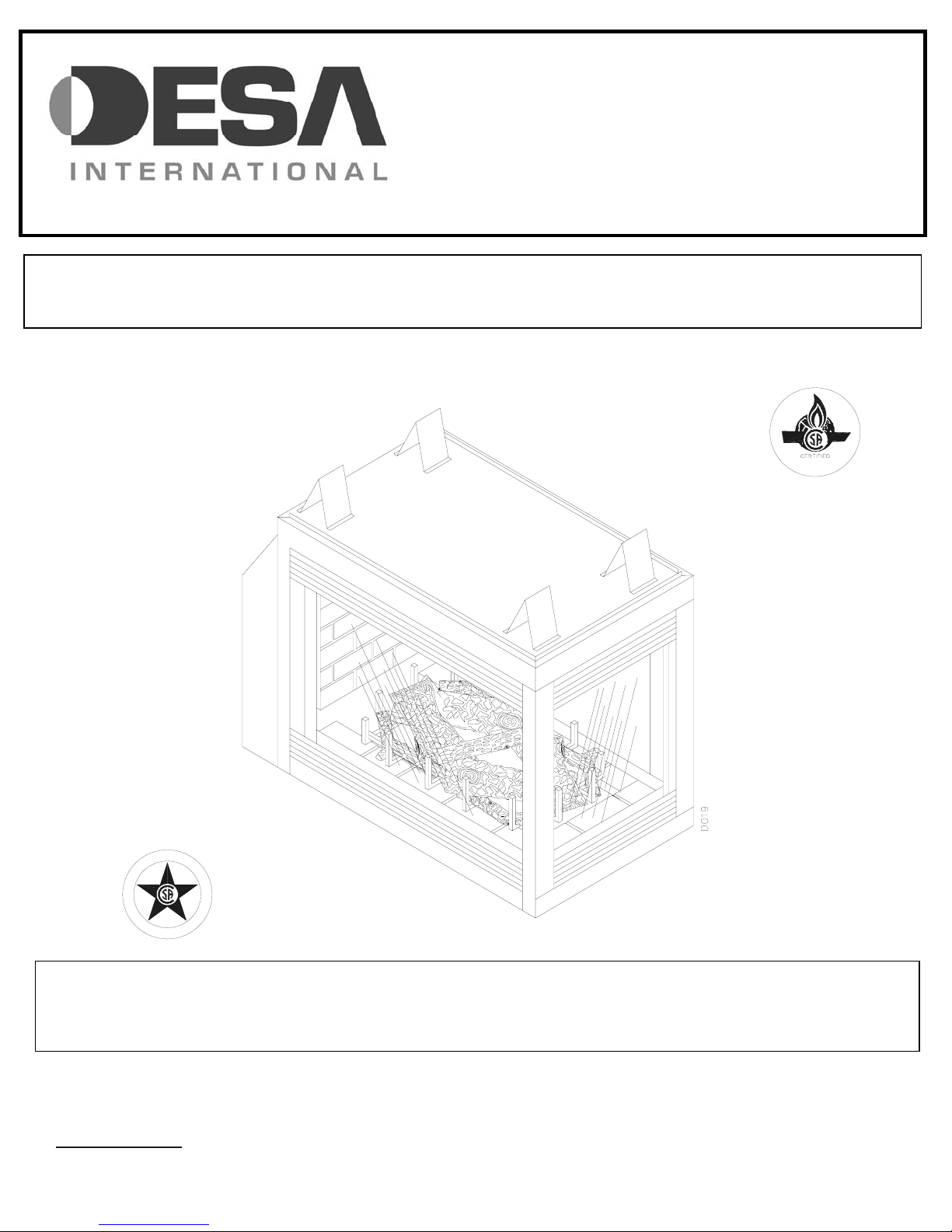
PENINSULA MODELS (V)DVF36
TPNA/TPNPA/TPNEA/TPNPEA
SEE THROUGH MODELS (V)DVF36
GRAVITY DIRECT VENT GAS FIREPLACE
TSTA/TSTPA/TSTEA/TSTPEA
INSTALLATION INSTRUCTIONS
SAVE THIS BOOK
This book is valuable. In addition to instructing you on how to install and maintain your appliance, it also contains information that will
enable you to obtain replacement parts or accessory items when needed. Keep it with your other important papers.
G
I
S
E
N
D
PENINSULA MODEL
SHOWN
C
E
D
R
E
I
T
F
This appliance may be installed in an aftermarket* permanently, manufactured (mobile) home, where not prohibited by state or local
codes. This appliance is only for use with the type of gas indicated on the rating plate. This appliance is not convertible for use with
other gases, unless a certified kit is used and installed by a qualified technician.
*Aftermarket: Completion of sale, not for purpose of resale, from the manufacturer.
I
DESA INTERNATIONAL
2701 INDUSTRIAL DRIVE P/N 56131
P.O. BOX 90024 REV C
BOWLING GREEN, KY 42101-9004 8/02
www.desatech.com

CONTENTS
• DIMENSIONS ---------------------------------------------------------------------------------------- PG. 2
• INTRODUCTION ---------------------------------------------------------------------------------------- PG. 3
• CLEARANCES ---------------------------------------------------------------------------------------- PG. 4
• FRAMING ---------------------------------------------------------------------------------------- PG. 5
• GENERAL VENTING ---------------------------------------------------------------------------------------- PG. 6
• VENTING INSTALLATION ---------------------------------------------------------------------------------------- PG. 7
• HORIZONTAL TERMINATION ---------------------------------------------------------------------------------------- PG. 11
• VERTICAL TERMINATION ---------------------------------------------------------------------------------------- PG. 12
• TERMINATION CLEARANCES ---------------------------------------------------------------------------------------- PG. 15
• WIRING CONNECTIONS ---------------------------------------------------------------------------------------- PG. 16
• REMOTE CONTROL ---------------------------------------------------------------------------------------- PG. 17
• GAS LINE HOOK-UP ---------------------------------------------------------------------------------------- PG. 18
• INSTALLING LOG SET ---------------------------------------------------------------------------------------- PG. 19
• GLASS DOORS ---------------------------------------------------------------------------------------- PG. 20
• LIGHTING INSTRUCTIONS ---------------------------------------------------------------------------------------- PG. 24
• TROUBLE SHOOTING GUIDE ---------------------------------------------------------------------------------------- PG. 26
• REPLACEMENT AND ACCESSORIES -------------------------------------------------------------------------------------- PG. 28
• WARRANTY ---------------------------------------------------------------------------------------- PG. 29
- 1 - For more information, visit www.desatech.com
D
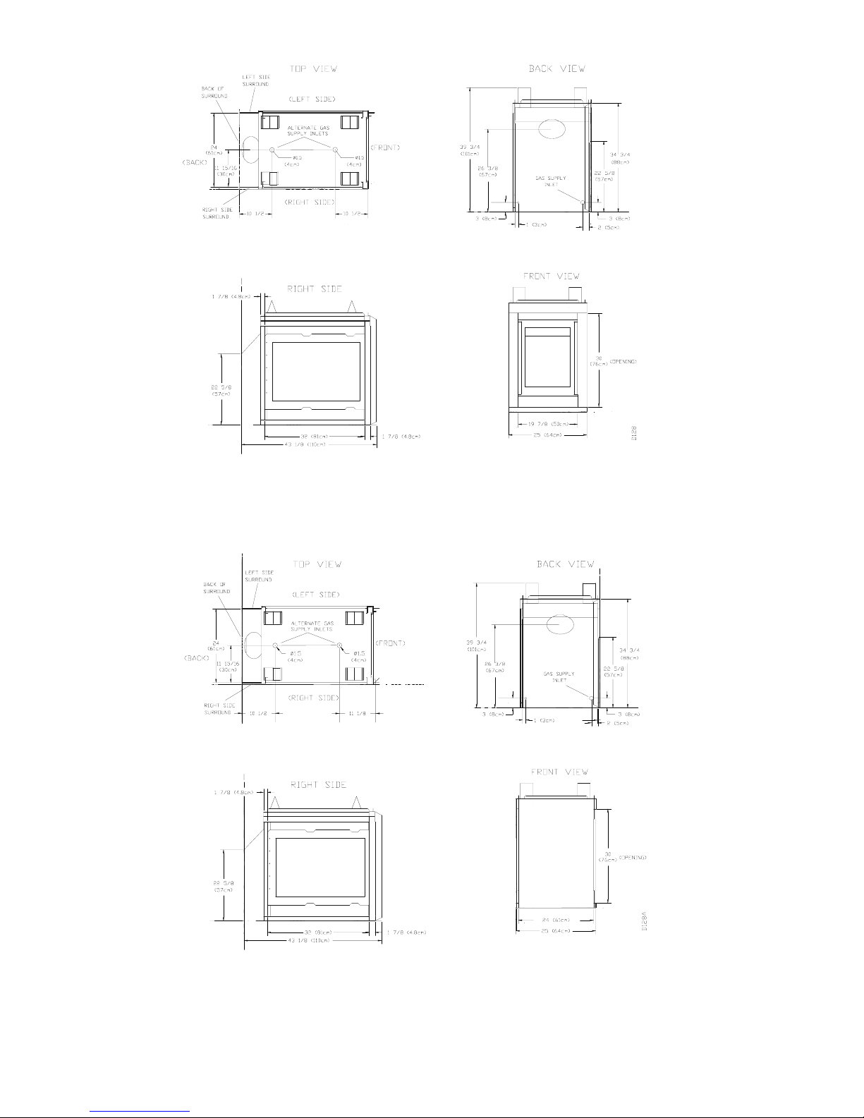
Figure 1 PENINSULA DIMENSIONS
Figure 2 SEE -THROUGH DIMENSIONS
- 2 - For more information, visit www.desatech.com
r
d
n
N
p
r
d
a
a
d
• Do not store or use gasoline or any other flammable
vapors or liquids in the vicinity of this or any othe
appliance.
• Due to high temperatures, the appliance should be
located out of traffic and away from furniture an
draperies.
• Do not place clothing or other flammable materials o
or near the appliance.
EVER leave children unattended when a fire is
•
burning in the fireplace.
WHAT TO DO IF YOU SMELL GAS
• Do not try to light any appliance.
• Do not touch any electrical switch.
• Do not use any phone in your building.
• Immediately call your gas supplier from a neighbor’s
phone. Follow the gas supplier’s instructions.
• If you cannot reach your gas supplier, call the fire
department.
WARNING: Improper installation, adjustment,
alteration, service or maintenance can cause injury,
roperty damage, or loss of life. Refer to this manual fo
assistance or additional information. Consult a qualifie
installer or local distributor.
CHECK LOCAL CODES BEFORE
INSTALLING THIS FIREPLACE.
FOR YOUR SAFETY
FOR YOUR SAFETY
INTRODUCTION
Models (V) DVF36TPNA/TPNPA series are three-sided direct
vent gas fireplaces and models (V) DVF36TSTA/TSTPA are
two-sided direct vent gas fireplace heaters with sealed
combustion chambers. Both use a millivolt gas control valve
with a millivolt ignition system.
Models (V) DVF36TPNEA/TPNPEA and (V) DVF36
STEA/TSTPEA use a direct spark ignition with a 24 VAC
control module. All models have HI/LO valve that controls
the flame height. These units can be equipped with louvers
for circulating or with panels for non-circulating operation.
Fan Kit models DVFFBK and DVFFBKT are available for
these units as an option. If you are uncertain as to what gas
your unit is equipped for, please check the rating plate located
in the interior of the appliance opening or consult your local
distributor of DESA products.
BEFORE BEGINNING THE INSTALLATION OF THE
FIREPLACE, READ THESE INSTRUCTIONS THROUGH,
COMPLETELY.
♦ This DESA fireplace and its components are safe
when installed according to this installation manual.
Unless you use DESA components, which has been
designed and tested for this appliance, you may cause
a fire hazard.
♦ The DESA warranty will be voided by and DESA
disclaims any responsibility for the following actions:
a) Modification of the fireplace, components, doors, blower,
fans, air inlet system and damper control.
b) Use of any component part not manufactured or approved
by DESA in combination with a DESA fireplace system.
c) Installation and/or operation in a manner other than
instructed in this manual.
d) Burning of anything other than the type of gas approved for
use in this gas appliance.
This appliance, when installed, must be electrically grounded
in accordance with local codes, or in the absence of local
codes, with the National Electrical Code, ANSI/NFPA 70 or
CSA C22.1 Canadian Electrical Code for Canada.
The installation must conform to local codes, or in the
absence of local codes, with the National Fuel Gas Code ANSI
Z223.1 (CAN B149. in CANADA)
This appliance complies with ANSI Z21.50, and CGA
2.22M98 as a VENTED GAS FIREPLACE and is listed and
tested by the Canadian Standards Association.
NOTICE: Installation and repair should be done by
qualified service person. The appliance should be
inspected before use and at least annually thereafter by
qualified service person. More frequent cleaning may be
required due to excessive lint from carpeting, bedding etc.
It is important that the control compartments, burners an
circulating air systems be kept clean.
SELECTING LOCATION
To determine the safest and most efficient location for your
appliance, consider the following guidelines:
1. The location must allow for all the proper clearances (see
section on Clearances and Mantle Clearances).
2. Consider a location where drafts, air conditioning ducts,
windows, or doors would not affect the heat output.
3. A location that avoids the cutting of joists or roof rafters
makes installation easier.
-3 - For more information, visit www.desatech.com
f
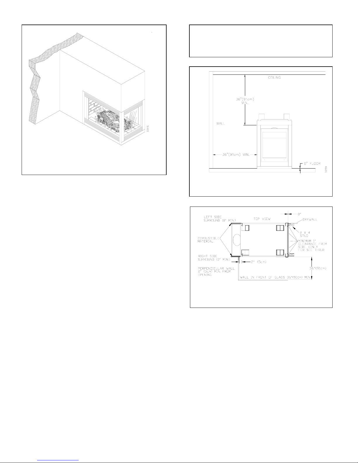
Figure 3 FIREPLACE INSTALLATION OF
PENINSULA MODEL SHOWN
IN SELECTING A LOCATION, THE FOLLOWING
PRECAUTIONS MUST BE OBSERVED:
1. A projection may be ideal for a new addition on an
existing finished wall. Refer to horizontal termination
configurations on page 11 or vertical termination
configurations on page 12.
2. Do not connect this appliance to a chimney system used
for a solid fuel-burning fireplace.
3. Due to high temperatures, do not locate this
appliance in high traffic areas or near furniture and
draperies.
4. Never obstruct the front opening of the appliance or the
flow of combustion and ventilation air. Keep control
compartments accessible.
5. Do not locate close to where gasoline or other flammable
liquids may be stored. The appliance must be kept clear
and free from combustible materials.
CLEARANCES
Minimum clearances to combustibles are:
• Back and side of surround …………… 0”
• Vent Surfaces (side and bottom) ………. 1”
• Top Vent Surface (horizontal run) ……… 2”
• Ceiling to Opening ………………………... 36”
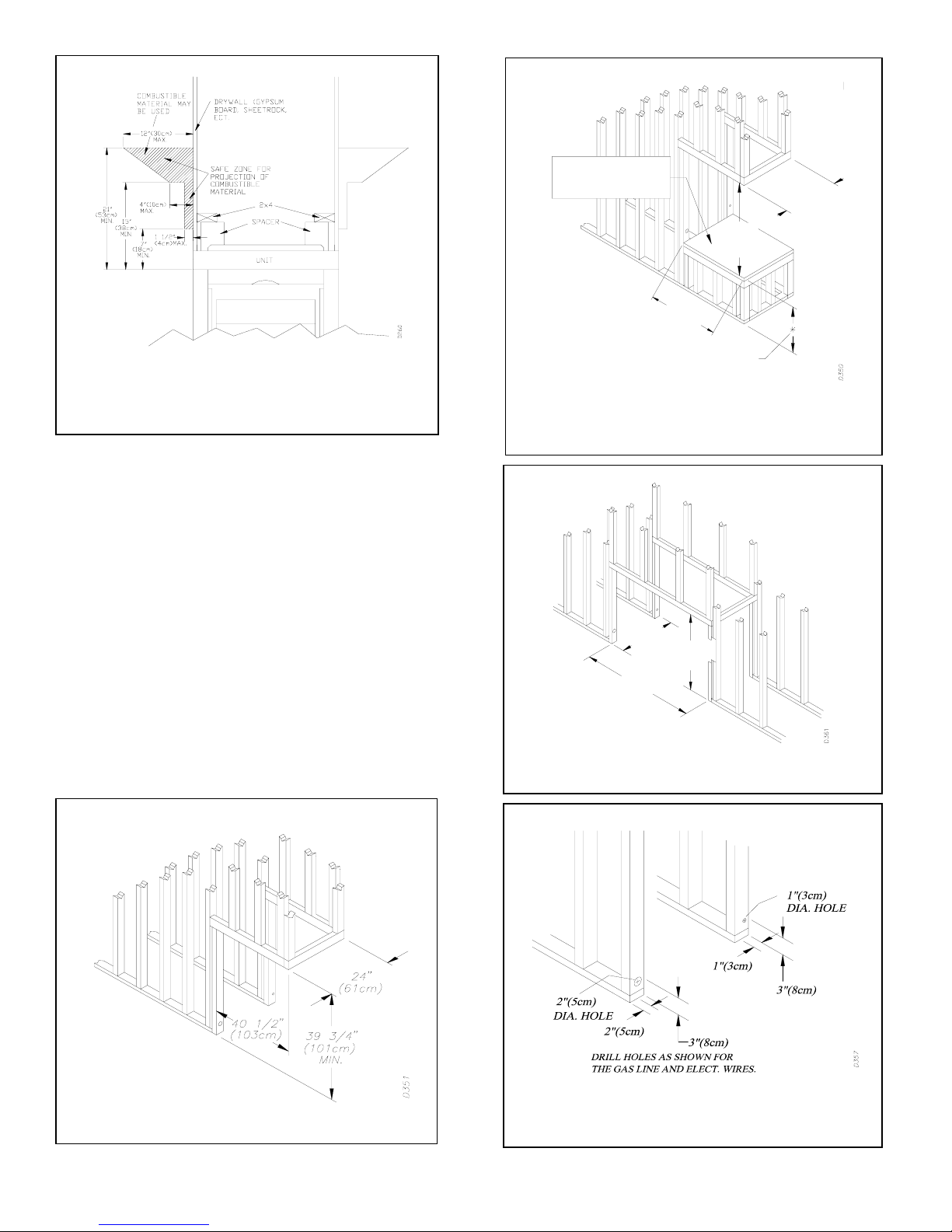
MANTEL CLEARANCES
Woodwork, such as wood trims, mantles, and other
combustible materials should not be placed within 7 inches
(178 mm) of the opening of this fireplace (see figure 6).
Combustible material above projecting more than 1-1/2 inches
(38 mm) from the appliance's front face must not be placed
less the 15 inches (381 mm) from the opening of the
appliance, (ref. NFPA Standard 211 Sec.7-3.3.3).
• Floor ………………………………………. 0”
• Wall to Front of Glass …………………….. 36”
• Perpendicular Wall to Opening of Unit …… 2”
• Top Spacer …………………………. 0”
CAUTION: Do not block required air spaces with
insulation or any other materials. Do not obstruct the
effective opening of the appliance with any type o
facing material.
Figure 4 MINIMUM CLEARANCES
PENINSULA MODEL
Figure 5 MINIMUM CLEARANCES
SEE-THROUGH MODEL
-4 - For more information, visit www.desatech.com
g
g
ure 6 MANTEL CLEARANCES FOR
Fi
PENINSULA AND SEE-THROUGH MODELS
(PENINSULA SHOWN)
FRAMING
Once the final location has been determined, observing
clearances for the vent termination, you may construct framing
using dimensions shown in figures 7, 8 and 9 depending on
your particular installation. If the appliance is to be installed
directly on carpeting, tile (other than ceramic), or any
combustible material other than wood flooring, the appliance
must be installed upon a metal or wood panel extending the
full width and depth of the appliance. There are three holes on
each side of the bottom of the unit where screws can be used
to secure the unit to the floor.
The gas supply line may be connected through the side
framing or alternately through the lower sub-flooring or a
platform base if provided (see figures 10 and 11). Depending
on the installation, refer to the appropriate illustration.
Figure 7 ROUGH OPENING (PENINSULA)
PLATFORM MUST BE
SOLID, FLAT, AND
FULLY SUPPORTED
39 3/4"
(101cm)
MIN.
24"
(61cm)
40 1/2"
(103cm)
AS REQUIRED BY DESIGN
AS LONG AS CEILING
CLEARANCE IS MAINTAINED
ure 8 ROUGH OPENING ON PLATFORM
Fi
(PENINSULA)
24"
(61 cm)
43 1/4"
(110 cm)
39 3/4"
(101 cm)
MIN.
Figure 9 ROUGH OPENING (SEE-THROUGH)
Figure 10
AND ELECTRICAL WIRES FOR BOTH MODELS
HOLE LOCATIONS FOR GAS LINE
-5 - For more information, visit www.desatech.com
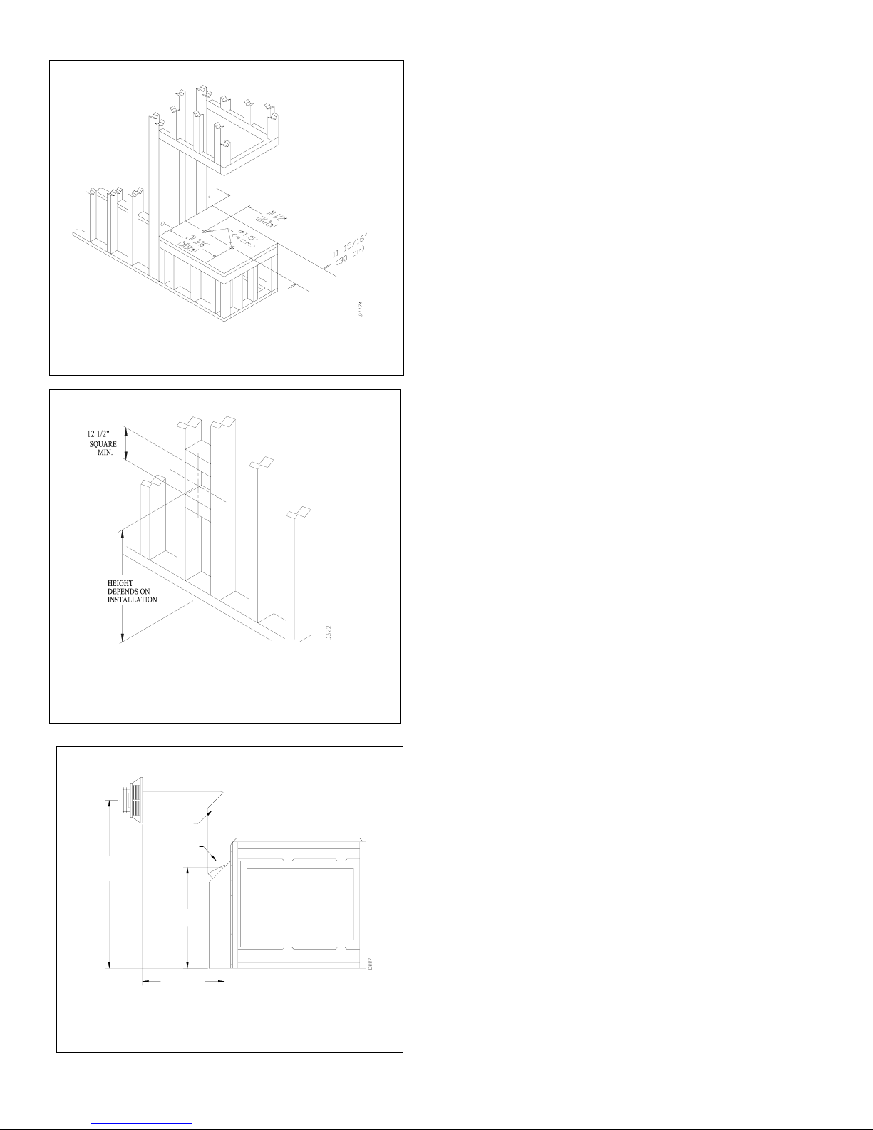
Figure 11
ALTERNATE GAS SUPPLY LOCATION
Figure 12 ROUGH OPENING FOR
INSTALLATION OF EXTERIOR VENT
TERMINAL
TERMINATION CAP
VERTICAL
HEIGHT DEPENDS
ON INSTALLATION
90 DEG.
ELBOW
45 DEG. ELBOW
26 3/8"
(67cm)
HORIZONTAL
LENGTH DEPENDS
ON INSTALLATION
Figure 13 VENT OPENING HEIGHT
FIREPLACE
GENERAL VENTING
These models are approved for use with Simpson, DuraVent®, rigid type direct vent pipe as supplied by DESA or
may be used with approved types of flexible vent pipe (i.e.
ECCO-FLEX™ or ZFlex™) when appropriately sized for a 8"
outer and 5" inner diameter application.
Your Fireplace is approved for venting either horizontally
through a sidewall, or vertically through a roofline using the
following guidelines:
• Only use DESA supplied or approved types of venting
components or venting kits. Do not mix different types of vent
components, modify vent components, or custom fabricate
vent components for use in any one installation.
• Minimum clearances between vent pipes and combustible
material is 1" (25mm), except where stated otherwise.
• Combustible material may be flush with the top front of the
fireplace with a maximum thickness of 3/4".
• Do not recess venting terminals into a wall or siding.
• Do not install vent terminals below grade level maintain a
minimum height of 12" above snow line.
• Do not terminate the venting system into an attic or garage.
• Install horizontal venting with a 1/4" rise for every 12" of
run towards the termination.
• There must not be any obstruction such as bushes, garden
sheds, fences, decks, or utility buildings within 24" from the
front of the termination cap.
• Do not locate termination cap where excessive snow or ice
build up may occur. Be sure to clear vent termination area
after snow falls to prevent accidental blockage of the venting
system. When using snow blowers, do not direct snow towards
vent termination area.
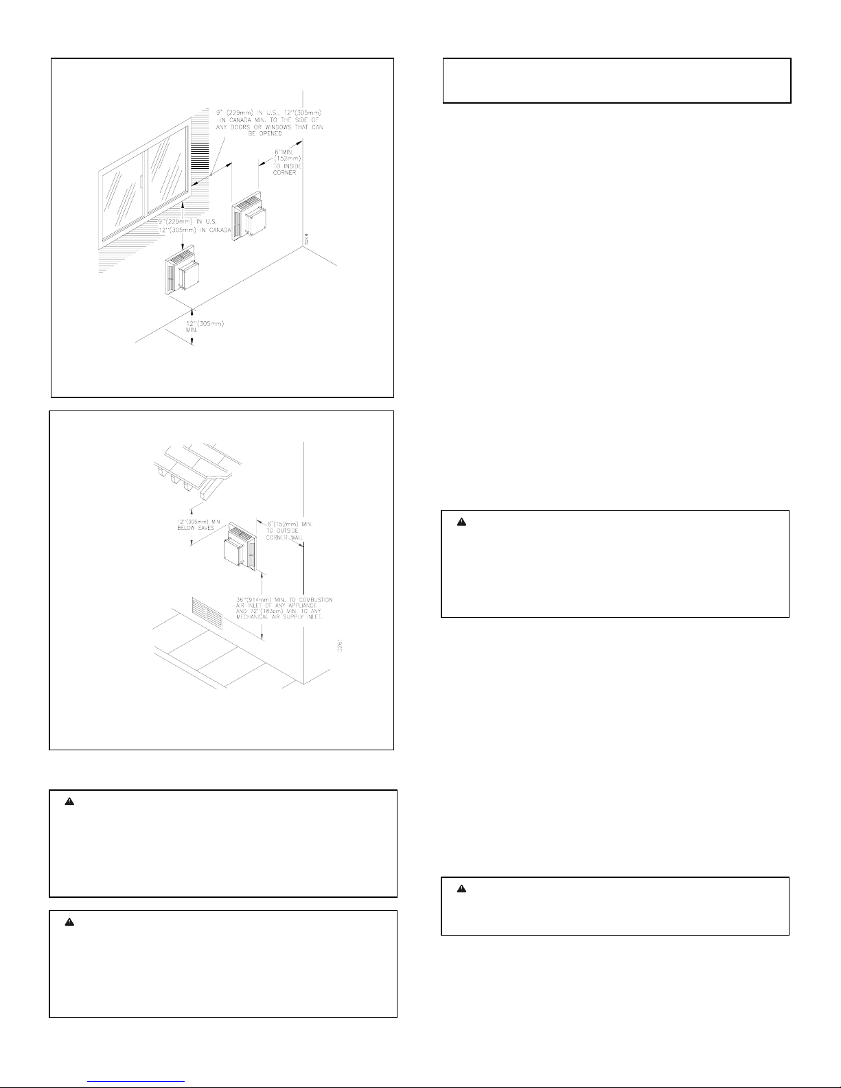
VENT TERMINATION CLEARANCES
The final position of your appliance depends on the location of
the vent termination in relation to the clearances that must be
observed as shown in figures 14 and 15.
You may avoid extra framing by positioning your fireplace
against an already existing framing member. The back of the
fireplace may be positioned directly against a combustible
wall.
* Check with local codes or with the current CAN/CGA B149
(.1 or .2) Installation Codes for Canada for Installations in the
USA follow the current National Fuel Gas Code, ANS Z223.1
also known as NFPA 54.
-6 - For more information, visit www.desatech.com
d
f
d
y
h
h
w
N
y
m
a
n
a
Figure 14 VENT CLEARANCES
Figure 15 VENT CLEARANCES
VENTING INSTALLATION
WARNING: Read all instructions completely an
thoroughly before attempting installation. Failure to do so
could result in serious injury, property damage or loss o
life. Operation of an improperly installed and maintaine
venting system could result in serious injury, propert
damage or loss of life.
WARNING: Seal all connections with hig
temperature silicone every time a vent connection is made.
Before joining elbows or pipes, apply a bead of hig
temperature silicone sealant to the male end of the elbo
or pipe. High temperature silicone must also be used to reseal any connections after maintenance to venting system.
OTICE: Failure to follow these instructions will void the
warranty.
INSTALLATION PRECAUTIONS
Consult local building codes before beginning the installation.
The installer must make sure to select the proper vent system
for installation. Before installing a vent kit, the installer must
read this fireplace manual and any vent kit instructions.
Only a qualified installer or service person should install a
venting system. The installer must follow these safety rules:
• Wear gloves and safety glasses for protection.
• Use extreme caution when using ladders or when working
on top of roofs.
• Be aware if electrical wiring locations in walls and
ceilings.
The following actions will void the warranty on your venting
system:
• Installation of any damaged venting component.
• Unauthorized modification of the venting system.
• Installation of any component part not manufactured or
approved by DESA. Installation other than as instructed
by these instructions.
WARNING: This gas fireplace and its vent assembl
must be vented directly to the outside. The venting syste
must NEVER be attached to the chimney serving
separate solid fuel-burning appliance. Each gas appliance
must use a separate vent system. Do not use in commo
vent system.
INSTALLATION PLANNING
There are two basic types of direct-vent installations:
• Horizontal Termination
• Vertical Termination (Rigid Vent Pipe Only)
It is important to select the proper length of vent pipe for the
type of termination you choose. It is also important to note the
wall thickness.
For Horizontal Termination: Select the amount of vertical
rise desired. The horizontal run of venting must have 1/4" rise
for every 12" of run towards the termination.
WARNING: Never run the vent downward as this
may cause excessive temperatures, which could cause
fire.
Up to two 90° elbows may be used in this vent configuration.
See Horizontal Termination Configurations page 11.
-7 - For more information, visit www.desatech.com
For Vertical Terminations: Measure the distance from the
N
fireplace flue outlet to the ceiling. Add the ceiling thickness,
the vertical rise in an attic or second story, and allow for
sufficient vent height above the roofline.
You may use up to two 90° elbows in this configuration. See
Vertical Termination Configurations on pages xx and xx.
Note: You may use two 45° elbows in place of a 90° elbow.
You must follow rise to run ratios when using 45° elbows.
For two-story applications, fire stops are required at each floor
level. If an offset is needed in the attic, additional pipe and
elbows will be required.
You may use a chase with a vent termination having exposed
pipe on the exterior of the house. See Installing Vent System
in a chase.
Your DESA direct-vent fireplace has been tested for a
minimum of 3 feet of vertical rise with accommodation for a
maximum of 11" wall thickness. Any horizontal application
longer than 12" must provide a minimum of one (1) foot of
vertical rise for every three (3) feet of horizontal run. The
maximum amount of horizontal run is 20' with 8' of vertical
rise (see Installation for Horizontal Termination, page 11).
The maximum vertical run is 30' (see Installation for Vertical
Termination, page 12).
INSTALLING VENT SYSTEM IN A CHASE
A chase is a vertical box-like structure built to enclose venting
that runs along the outside of a building.
OTICE: Treatment of firestops and construction of the
chase may vary from building type to building type. These
instructions are not substitutes for the requirements of local
building codes. You must follow all local building codes.
NOTE: When installing in a chase, you should insulate the
chase as you would the outside walls of your home. This is
especially important in cold climates. A minimum clearance
between vent pipes and combustible materials such as
insulation is 1".
After framing the chase install the venting system by
following the installation instructions for vertical installations
on page xx.
INSTALLATION FOR HORIZONTAL TERMINATION
1. Determine the route your horizontal venting will
take.
NOTE: The location of the horizontal vent termination on the
exterior wall must meet all local and national building codes
and must not be easily blocked or obstructed.
WARNING: Do not recess a vent terminal into a wall
or a siding. This will cause a fire hazard.
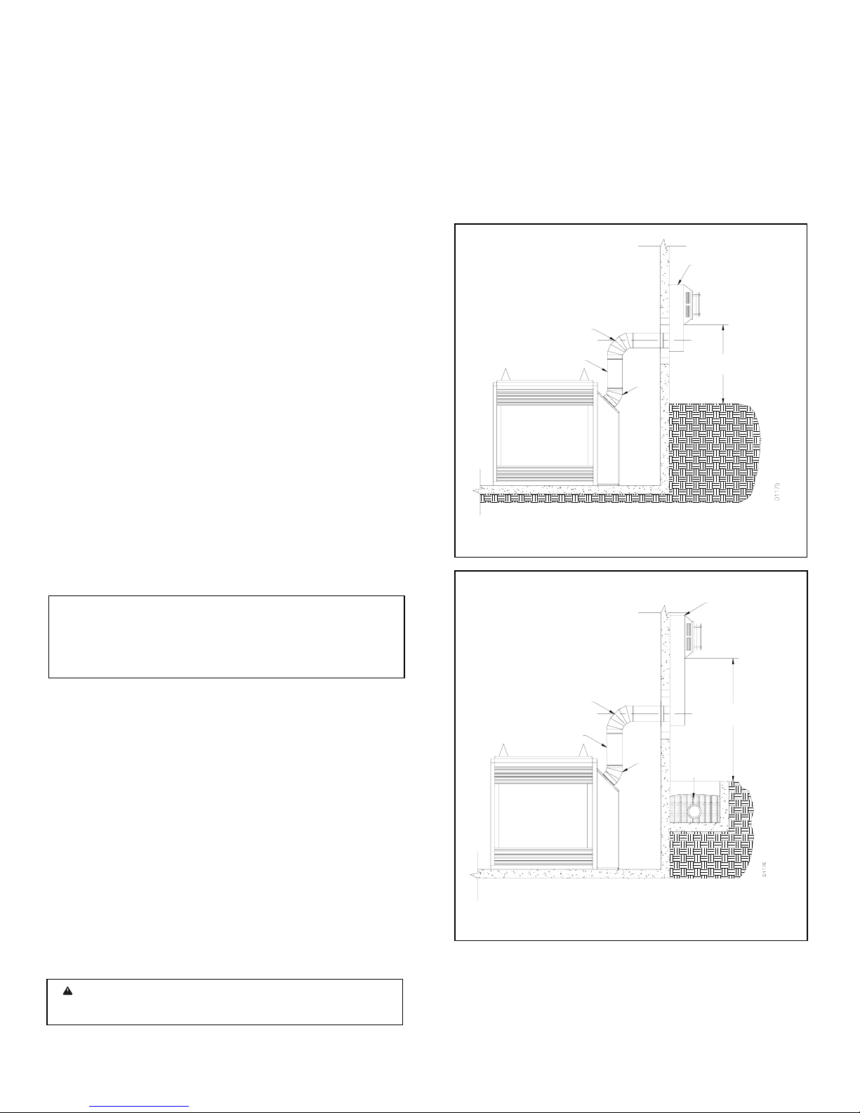
Snorkel terminations are available for terminations requiring a
vertical rise on the exterior of the building (see figures 16 and
17). Snorkel kits are available for rigid pipe applications only
to provide for a 14" rise and a 36" rise (see page 14). Follow
the same installation procedures used for standard horizontal
terminations. If installing the snorkel termination to raise the
vent termination from below grade level such as in a basement
installation, you must provide proper drainage to prevent
water from entering the snorkel termination (see figure 17).
Do not back fill around the snorkel termination.
SNORKEL
1' MINIMUM
90°
12" MIN.
45°
Figure 16 SNORKEL TERMINATION
36" SNORKEL
1' MINIMUM
90°
45°
12" MIN.
DRAINAGE
Figure 17 SNORKEL TERMINATION W/ DRAIN PIPE
2. Rigid vent-pipes and fittings have special twist-lock
connections. Assemble the desired combinations of pipe and
elbows to the appliance adapter with pipe seams oriented
towards the wall or floor.
-8 - For more information, visit www.desatech.com
 Loading...