

Page 1
OUTDOOR ELECTRIC PATIO TABLE UMBRELLA STAND AND
FOOT WARMER SERVICE MANUAL
MODELS PD15EA, PG15EA, PL15EA AND PV15EA
1500 WATT 120V 60HZ 12.5 AMPS
IMPORTANT: Read and understand this manual
before assembling, starting or servicing this
product. When using electrical products, basic
safety precautions should always be followed to
reduce the risk of fire, electric shock and injury to
persons. Keep this manual for future reference.
TABLE OF CONTENTS
Safety Information ............................................... 2
Pre-Operating Instructions .................................. 3
General Information ............................................. 4
Product Identification ........................................... 5
Installation ........................................................... 5
Operation ............................................................. 5
Cleaning .............................................................. 5
Save this manual for future reference.
For more information, visit www.desatech.com
Wiring Diagram .................................................... 5
Safety Requirements ........................................... 6
Cautions .............................................................. 6
All Systems Working Together ............................. 6
Troubleshooting ................................................... 6
Reassembly Points .............................................. 8
Illustrated Parts Breakdown and Parts List ....... 10
Page 2

SAFETY INFORMATION
IMPORTANT: Read this manual
carefully and completely before
trying to assemble, operate or
service this product. When using
electrical products, the following
basic safety precautions should
always be followed to reduce the
risk of fire, electric shock and
injury to persons.
WARNING: As with most electrical appliances, electrical parts
in this product are electrically live
even when switch is off.
1. Do not use this product if the power circuit
does not have ground fault circuit interrupt
(GFCI) protection. GFCI should be wired
into the homes electrical circuit by a qualified
electrician.
2. This product must be used on a grounded
supply circuit.
3. Product must be used on a 15 or 20 amp
maximum overcurrent protection circuit.
4. DO NOT use indoors or plug this product into
an indoor circuit.
5. Avoid the use of an extension cord. Extension
cord may overheat and cause risk of fire. If you
must have an extension cord, the cord shall be
minimum size of 14 awg and not rated less
than 1875 watts. Use only 3 wire cord type
(3 prong plug) marked for outdoor use.
6. Do not use 16 or 18 gauge extension cords.
Damage to household wiring and/or fire could
result.
7. Avoid overheating the cord. DO NOT run cord
under outdoor carpeting. DO NOT cover cord
with throw rugs, runners or the like. Arrange
cord away from traffic area and where it will
not be tripped over.
8. Do not run cord through doorways, holes in
floors or walls.
9. DO NOT operate product with a damaged
cord or plug or after the product malfunctions,
has been dropped or damaged in any manner.
Return product to service center for examina
tion, electrical or mechanical adjustment or
repair.
10. Do not remove, bend or modify any metal
prongs or pins of cord.
2
www.desatech.com
11. Do not allow the legs of chairs or the table to
rest on the power cord.
12. Always unplug product after use.
13. When unplugging, be sure to pull by the plug
and not the cord.
14.
Keep electrical plug dry and off of wet
surfaces.
15. Do not place or store where product can fall or
be pulled into swimming pool or body of water.
If product falls into water, unplug immediately.
DO NOT REACH INTO WATER. If water is
above the air intakes (see Figure 3, page 4) or
product is totally immersed in water, dispose
of heater properly.
16. Do not use near or place where standing water
can occur.
17. Do not hose down or pressure wash.
18. For outdoor use only in temperatures above
freezing.
19. Use product only for intended outdoor use as
described in this manual. Any other use not
recommended by the manufacturer may cause
fire, electric shock, or injury to persons.
20. Do not operate this product in the rain.
21.
Keep combustible and flammable materials,
such as gasoline and paint thinner, at least 3 ft
(0.9 m) from all sides of the product. DO NOT
place combustible liquids above the product.
Avoid spilling combustible liquids on the
product.
22. This product has hot and arcing or sparking
parts inside. Do not use where flammable
vapors are present
23. DO NOT insert or allow foreign objects to
enter any ventilation or exhaust opening as this
may cause an electric shock or fire or damage
the product.
24. To prevent a possible fire, DO NOT block
air intakes in any manner. DO NOT use on
soft surfaces such as grass, wet soil or where
openings may become blocked.
25. Do not permanently block air exhaust in any
manner.
26. DO NOT locate product on top of carpet.
27. Warn children of the risk of death by electri
cal shock. Extreme caution is necessary when
any product is used by or near children or
animals.
28. DO NOT attempt to repair or adjust any
electrical or mechanical parts on this unit.
Unauthorized repairs or alterations of this
product may increase the risk of fire, electrical
shock or injury to persons. The inside of the
unit contains no user serviceable parts. All
servicing should be performed by qualified
personnel only.
115423-01A
-
Page 3
SAFETY INFORMATION
RESET
TEST
WARNING
Continued
29. Use only in accordance with the local ordinances and codes.
30. This product is not to be used as the sole
support for an umbrella. Umbrella must be
supported by a table.
31. Do not use or install umbrella into product
at temperatures below freezing. A damaged
product could result in the risk of fire, electric
shock and injury to persons.
32. Do not use this at any elevation above floor
level. Do not place on a table.
33. Locate product so “ON” light can be easily seen
10 ft (3.05 m) around and 5 ft (1.52 m) above.
34.
If a table cloth is used on the table above the product, secure it to prevent movement due to wind.
35. Do not use in temperatures above 75° F
(28.9° C). Nuisance tripping of manual reset
thermal protector can occur.
36. Take precautions to prevent spilling drinks on
product.
37. If the product will not operate, see specific
instructions in Troubleshooting, page 6.
38. Save these instructions for future reference.
This product contains and/or
generates chemicals known to
the state of California to cause
cancer or birth defects or other
reproductive harm.
PRE-OPERATING
INSTRUCTIONS
GROUND FAULT INTERRUPTER
• Since 1971 the National Electric Code (NEC)
has required Ground Fault Circuit Interrupter
devices on all outdoor circuits.
•
If your residence was built before 1971, check with
a qualified electrician to determine if a Ground
Fault Circuit Interrupter protector exists.
• Do not use this product if the circuit does not
have a GFCI protection.
• Do not plug this product into an indoor circuit.
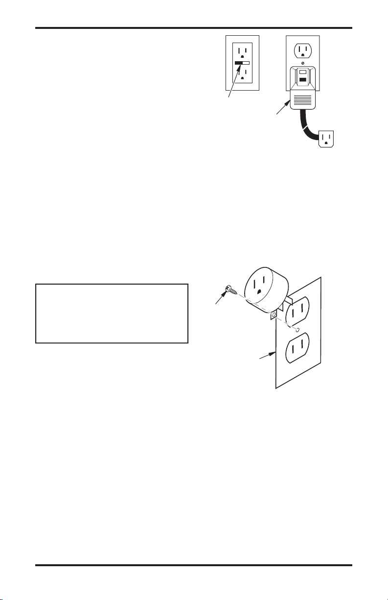
• Typical accepted GFCI devices are shown in
Figure 1.
• Avoid the use of an extension cord. Extension
cord may overheat and cause risk of fire. If you
must have an extension cord, the cord shall be
minimum size of 14 awg and not rated less than
1875 watts. Use only 3 wire cord type (3 prong
plug) marked for outdoor use.
115423-01A 3
www.desatech.com
Test and
Reset
Buttons
GFCI Cord
Adapter
Figure 1 - GFCI Options
PLUG ADAPTER
IMPORTANT: This product must be used on a
grounded supply circuit.
An adapter as shown in Figure 2 is available for
connecting three-prong grounding type plugs to
two-slot receptacles. The green grounding lug
extending from the adapter must be connected to
a permanent ground such as a properly grounded
outlet box.
Metal
Screw
Cover of
Grounded
Outlet Box
Figure 2 - Plug Adapter
Page 4
GENERAL INFORMATION
ARRANGEMENT OF MANUAL
This manual contains information and service
procedures to assist the service technician in
understanding and correcting problems on DESA
Heating Products Umbrella Stand and Electric
Foot Warmer. The first section of the manual
contains basic information concerning the operation of the different components in the heater.
This information should be reviewed by service
personnel to provide a basic understanding of how
the components function in the working system.
The Troubleshooting section of this manual is
intended to provide a quick reference concerning
conditions which result in customer complaints.
These procedures will help the service technician
quickly diagnose a malfunctioning heater. The
illustrations in this manual may not necessarily
depict the actual heater model and are intended
for reference ONLY.
TECHNICAL SERVICE DEPARTMENT
The Te chn ica l Serv ice Department, located
in Bowling Green, Kentucky, is committed to
assisting our Authorized Service Centers to increase their service knowledge so that they can
provide prompt, efficient service. This Service
Manual covers the majority of problems that are
associated with the heaters. However, as with
any product, certain problems can arise which
have not been covered. If such problems arise,
please call the Technical Service Departmentʼs
number, 1-866-672-6040 or visit our website at
www.desatech.com, to address these technical
problem areas. If you need assistance for ordering
parts, billing questions, etc. you should contact
1-866-672-6040.
SERVICE PREPARATION
A clean work area at the start of each job is essential for efficient service work. Heaters which are
extremely dirty should be cleaned prior to service.
Cleaning will occasionally uncover the problem
area. Tools needed for the job should be obtained
before work is started. Delays resulting from locating tools result in lost time and wages.
Use caution and common sense when working on
a heater. Always remember that electrical parts can
result in potential shock. Heater parts are hot dur
ing operation, which could result in burns.
TOOLS REQUIRED
In addition to common hand tools, the service
shop should have the following tools and instru
ments for proper repairing of the heaters. These
4
www.desatech.com
instruments will be referred to throughout this
manual.
INSTRUMENT RANGE
1/4" Nut Driver N/A
3/16" Nut Driver N/A
11/32" Nut Driver N/A
1/8" Allen Wrench N/A
3/4" Open end wrench N/A
Torque Wrench N/A
Multimeter*
*Available at most electronic stores.
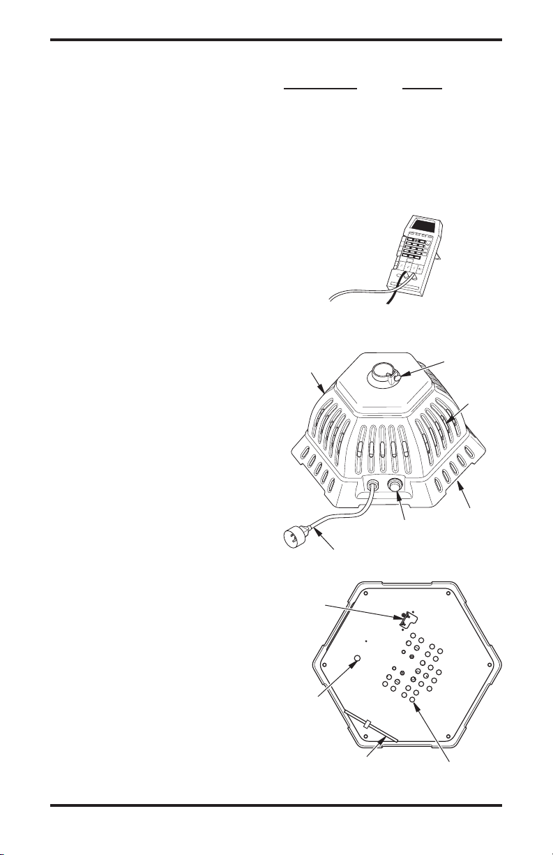
Multimeter
0-250 VAC/0-200 Ohm
PRODUCT
IDENTIFICATION
Body
Lighted
On/Off
Power Cord
Tip
Switch
Access to
-
Thermal
Limit Switch
-
Push
Rod
Figure 3 - Umbrella Stand Warmer
Switch
Thumb
Screw
Air Intake
(opening
to bottom
of warmer)
Air Intakes
115423-01A
Warm
Air
Exhaust
(Bottom
View)
Page 5

INSTALLATION
POWER PLUG
120V 60Hz
GREEN
BLACK
N
L
N
L
WHITE
ON/OFF
SWITCH
HEATING
ELEMENT
MOTOR
BLACK
MANUAL RESET
THERMAL LIMIT
SWITCH
TIP SWITCH
BLACK
GREEN
BLACK
BLACK
WHITE
WHITE
1. Locate product under outdoor patio table on
hard, level, dry surface. Post of tip over switch
must be on solid surface for product to work.
Listen for the “click”. See Figure 3 for switch
location.
2. Slowly lower umbrella pole into product. Do
not drop pole, it may damage product.
3. Tighten thumb screw of product to secure pole.
Pole will be approximately 7 inches higher
than if used without this product.
4. Make sure the product is in the OFF posi
tion before plugging into a grounded GFCI
protected 120V 60 HZ outlet.
5. Avoid overloading your circuit by not using
other high wattage products in the same outlet.
At 1500 watts, this unit draw 12.5 Amps.
OPERATION
IMPORTANT: Review and understand the warnings in the Safety
Information section, page 2.
They are needed to safely operate this product. Follow all local
ordinances and codes when
using this product.
1. Push lighted ON/OFF switch.
2.
The power light will remain lit during
operation.
3. Stay back from product until all water or
debris has blown clear.
4. Product will warm in a few minutes.
WIRING DIAGRAM
-
SAFETY REQUIREMENTS
This service manual is intended for use by individuals with an adequate knowledge of electrical
and mechanical skills. Attempts to repair this
heater by individuals without those skills can result
in personal injury, as well as property damage
CLEANING
DURING SEASON CARE
Always unplug the product before moving or
cleaning.
1. Do not disassemble. Carefully wipe the exte
rior of unit with a soft, damp cloth.
2. After cleaning, be sure to completely dry the
unit with a cloth or towel.
AFTER SEASON CARE
Store product indoors in a dry location. No maintenance is required for this product.
115423-01A 5
-
www.desatech.com
Page 6

CAUTIONS
A
C
Air To Be Heated Heated Air
D
E
B
1. Before servicing, disconnect the heater from
the electrical power source by removing the
electrical plug from the wall receptacle.
Note: When certain tests require electrical power
to be applied, connect electrical power only for
the time necessary to complete the test.
2. Do not bypass safety devices except when
instructed to do so during troubleshooting
procedures.
3. If replacement parts are necessary, do not
substitute with non-factory parts (use only
factory authorized replacement parts).
4. Make sure all electrical connections are secure
and correct prior to connecting heater to a
grounded electrical power source.
ALL SYSTEMS WORKING
TOGETHER
There are three basic systems within the heater, the
heating system, air system and safety system.
A tubular heating element (A) warms the sur
rounding air.
A fan (B) on one end of a motor (C) draws air into
the product. This air is directed over the heating
element to create warm heated air out.
An over temperature switch (D) shuts the heater off
in the abnormal event a motor were to fail.
A tip over switch (E) shuts the heater off in the
event the product is tipped over.
TROUBLESHOOTING
CAUTION: Risk of electric
shock.
If your product fails to operate:
1. Make sure the electrical outlet GFCI or circuit
breaker and extension cord is working.
2. Check for operation of tip switch. The ON/
OFF switch light can be on but the tip switch
OFF. Move product until a “click” is heard.
To prevent damage of tip switch post, do not
slide product.
3. Look for obstructions around fan. If you find
an obstruction, turn the product OFF and
UNPLUG THE PRODUCT. Have the product
serviced by a qualified individual.
4. Check for tripped thermal protector. Motor
and heating element do not operate. Wait 10
minutes for product to cool. Push reset button.
See Thermal Limit Switch below.
THERMAL LIMIT SWITCH
-
If product is used in temperatures below 75° F
(28.9° C), the limit switch should not require
resetting unless there is a malfunction. If a mal
function does occur, have the product serviced by
an authorized service center.
Resetting Thermal Limit Switch
1. Unplug product.
2. Allow product to cool.
3. Turn product upside down.
4. Remove plug on bottom.
5. Insert provided plastic push rod through hole
and guide to small red button on thermal
limit switch (see Figure 5). A flashlight will
improve visibility.
6. Lightly push red button to reset switch.
-
Figure 4 - System Operation
INSPECTION
Check for damage in the following ways:
1. Examine exterior of plastic shroud and inside
pole receiver for cracks. Replace shroud if
cracks are found.
2. Examine cover of on/off switch for cracks.
Replace switch if cracks are found.
6
www.desatech.com
Air Intake Openings
Push Rod
Access to
Thermal
Limit Switch
Figure 5 - Resetting Thermal Limit Switch
115423-01A
Page 7

TROUBLESHOOTING
Continued
7. Replace removed plug in hole. Perform a trial
operation.
8. If repeated resetting of the thermal limit switch
is required, have the product serviced by an
authorized service center.
OBSERVED FAULT
Tubular heating element heats up but
no rush of warm air is felt at outlet vents
Rotate fan by hand to determine if fan
rotates easily
Fan is difficult Fan rotates easily
to rotate by hand
1 Fan or motor 3 Open motor coil
obstructed
2 Dry motor bearing
Test Procedure
1. Fan or Motor Obstructed
Remove obstruction. Clean heater.
2. Dry Motor Bearing
If the fan is difficult to turn, then motor bearings
are defective. Bearings are permanently lubricated,
therefore motor should be replaced.
3. Open Motor Coil
Disconnect motor wires (black and white). Attach
the ohmmeter leads to the motor wire terminals.
Using the 0 to 200 ohm scale, measure the resistance of the motor coil. If the resistance is not
approximately 6.0 to 6.4 ohms at 73° F, the motor
is defective and should be replaced.
No te: Re sis tances may var y due to motor
temperature.
OBSERVED FAULT
Motor starts and runs but cool air is felt
Does tubular heating element heat up?
No Yes
WARNING: WARNING:
Hot Surface! Hot Surface!
1 Look for defective 3 Check for blocked
tubular heating air intake openings
element
2 Open tubular heating
element
Test Procedure
1. Look for Defective Tubular Heating
Element
After approximately 2 minutes the tubular heating element should glow a dull red when placed
in a dark area.
2. Open Tubular Heating Element
Disconnect element wires (black and white).
Attach the ohmmeter leads to the element wire
terminals. Using the 0 to 200 ohm scale, measure
the resistance of the element. If the resistance is
not 8.5 to 11 ohms at 73° F the element is defective
and should be replaced.
vary due to element temperature.
3. Check for Blocked Air Intake Openings
Check for blockages around vent openings at bot
tom of heater (see Figure 5, page 6).
Note: Resistances may
-
Figure 7 - Testing Heating Element
Figure 6 - Testing Motor
115423-01A 7
www.desatech.com
Page 8

REASSEMBLY POINTS
Because this is an outdoor product where the
control of water is important, the following steps
for assembly must be followed.
1. The closed cell foam gasket must seal the hex
shaped pan to the inside of the plastic housing
(see Figure 8). The seal is to be completely
even in the corners of joined parts.
2. The tubular heating element rubber sealing
washers must be against the top surface of the
steel pan and under the brass flat washers as
shown in Figure 9. Nuts on opposite side of pan
must be tightened 1/2 turn past finger tight.
3. Apply a
4. The tip switch cover must isolate tip switch
5. To complete grounding of heater, all ground
6. No wires should be seen through openings in
SMALL drop of thread locking sealant (rated to 300° F, such as Loctite Thread
Locker Blue) to each of the thermal reset
switch mounting screws (see Figure 10).
Torque screws to 6 to 9 inch-pounds.
from metal base as shown in Figure 11.
wires must be fixed with screws as originally
assembled by the manufacturer. Additionally,
internal tooth washers must be against the steel
pan and under nuts as shown in Figure 12, for
the tubular heating element.
bottom of heater (see Figure 13).
Figure 10 - Thermal Reset Switch
Mounting Screws
Figure 11 - Tip Switch Cover
Figure 8 - Foam Gasket
Brass Flat
Washer
Figure 9 - Tubular Heating Element
Sealing Washers
8
Figure 12 - Grounding of the Tubular
Rubber
Sealing
Washer
www.desatech.com
Figure 13 - Air Openings in Bottom of
Heating Element
Heater
115423-01A
Page 9

REASSEMBLY POINTS
Continued
7. Tubular heating element must be flush against
bracket (see Figure 14). This centers the ele
ment to the center hole in metal pan.
8. Fan must be located with set screw at back of
and on flat of shaft (see Figure 15).
9. Heater is equipped with heat reflective tape.
If loose or damaged, replace tape as shown in
Figures 16 and 17. Tape edge should touch top
of louver openings.
Figure 14 - Heating Element and Bracket
Back of, and
Fan Set
Screw
Flat of Motor
Shaft
-
Figure 16 - Reflective Tape and Louvers
Figure 17 - Reflective Tape on All Louvers
Motor
Shaft
Figure 15 - Fan and Motor
115423-01A 9
www.desatech.com
Page 10

ILLUSTRATED PARTS BREAKDOWN
19
1
7
28
14
16
9
8
2
17
18
27
26
15
Requires
Loctite Thread
Locker Blue
6
3
22
23
20
13
11
10
21
2
12
24
25
Steel
Nut
Brass
Washer
Rubber Seal
Bottom View
5
4
10
www.desatech.com
115423-01A
Page 11

PARTS LIST
This list contains replaceable parts used in your product. When ordering parts, be sure to provide the
correct model and serial numbers (from the identification decal), then the part number and description
of the desired part.
KEY PART
NO. NUMBER DESCRIPTION QTY.
1 113560-01 Galvanized Steel Base 1
2 M11084-39 Screw, #8-18 x 1/2" Hex Head 12
3 113053-01 Plastic Umbrella Body 1
4 113152-01 Power Cord 1
5 113570-01 Bushing, Power Cord Strain Relief 1
6 M10908-14 Screw #8-32 x 3/8" Hex Head 2
7 113562-01 Motor, "C" Frame 1
8 097384-02 Nut, Captive Washer #8-32 2
9 M12461-14 Screw, #8-32 x 3/8" Hex Head 2
10 113563-01 Fan 1
11 113059-01 Element, 1500 Watt Heating 1
12 103457-01 Button Plug 1
13 114679-01 Screen Guard Kit 1
14 114025-01 Manual Reset Limit Switch 1
15 M10908-2 Screw, #6-32 x 3/8" Hex Head 2
16 107729-01 Tip Switch 1
17 097968-07 Screw, #4-40 x 3/4" Hex Head 2
18 097384-04 Captive Washer Nut 2
19 ** Mounting Pan Kit 1
20 113558-01 On/Off Switch 1
21 097785-10 Gasket Seal 1
22 113578-01 Thumb Screw, 1/4 - 20 x 1 1
23 113577-01 Nut, 1/4-20 Weld 1
24 113200-01 Tip Switch Actuator 1
25 WLI-8 Lock Tooth Washer 2
26 114024-01 Tip Switch Cover 1
27 114030-01 Push Rod 1
28 113251-02 Rubber Motor Mount 1
PARTS AVAILABLE - NOT SHOWN
113579-01 Black Wire Assembly 14 AWG, 6.5" 1
113579-02 Green Wire Assembly 14 AWG 2
113579-03 Black Wire Assembly 14 AWG, 9.5" 1
098303-02 Motor Ground Wire Screw, #6-20 x 5/16" Hex Head 1
113613-01 Identification Decal 1
113611-01 Cord Tag 1
114966-02 Warning Decal 1
115498-01 Heat Reflective Tape, 2 x 4.5" 6
**Not a field replaceable part.
115423-01A 11
www.desatech.com
Page 12

115423 01
2701 Industrial Drive
P.O. Box 90004
Bowling Green, KY 42102-9004
www.desatech.com
NOT A UPC
115423-01
Rev. A
10/04
 Loading...