

Desa MD18, VVDR24, FVDR24, MD24, VVDR3 Owner's Operation And Installation Manual
...
VENTED DECORATIVE NATURAL GAS LOGS
OWNER’S OPERATION AND
INSTALLATION MANUAL
For more information, visit www.desatech.com
For more information, visit www.desatech.com
Vanguard Burner Models VVSR18, VVSR24, VVDR18, VVDR24, and VVDR30
For Use with Log Sets:
Hanover Round Oak Log Models VSLR18 and VSLR24
Kingston Split Oak Log Models VDLCR18, VDLCR24 (Shown), and VDLCR30
FMI Burner Models FVSR18, FVSR24, FVDR18, FVDR24, and FVDR30
For Use with Log Sets:
Arlington Round Oak Log Models FSLR18 and FSLR24
Manchester Split Oak Log Models FDLCR18, FDLCR24 and FDLCR30
Comfort Glow Oxford Oak Log Set and Burner Models:
CVSR18 and CVSR24
Comfort Glow Amherst Oak Log Set and Burner Models:
CPVSR18 and CPVSR24
Comfort Glow Berkshire Oak Log Set and Burner Models:
CVDR18, CVDR24, and CVDR30
Comfort Glow Shenandoah Oak Log Set and Burner Models:
LBFL18 and LBFL24
Comfort Glow Conventry Oak Log Set and Burner Models:
LVDR18, LVDR24 and LVDR30
Comfort Glow Mendocino Oak Log Set and Burner Models:
BFLT18 and BFLT24
Comfort Glow Malibu Drift Log Set and Burner Models: MD18 and MD24
RGA 2-72
APPROVED
TESTED AND
LISTED BY
WARNING: If the information in this manual is not
followed exactly, a fire or explosion may result causing property damage, personal injury, or loss of life.
— Do not store or use gasoline or other flammable
vapors and liquids in the vicinity of this or any
other appliance.
— WHAT TO DO IF YOU SMELL GAS
• Do not try to light any appliance.
• Do not touch any electrical switch; do not use
WARNING: Improper installation,
adjustment, alteration, service, or
maintenance can cause injury or
property damage. Refer to this
manual for correct installation and
operational procedures. For assistance or additional information consult a qualified installer, service
agency, or the gas supplier.
any phone in your building.
• Immediately call your gas supplier from a
neighbor’s phone. Follow the gas supplier’s
instructions.
• If you cannot reach your gas supplier, call the
fire department.
— Installation and service must be performed by a
qualified installer, service agency, or the gas
supplier.
WARNING: This appliance is for
installation only in a solid-fuel burning masonry or UL127 factory-built
fireplace, constructed of noncombustible material, and connected
to a working flue. (See page 7 for
minimum flue opening.)
WARNING: This is a gas-fired appliance. It uses air (oxygen) from the room in which it is installed.
Provisions for adequate combustion and ventilation air must be provided. Refer to the
National
Fuel Gas Codes, ANSI Z233.1/NFPA 54, Section 5.3, Air for Combustion and Ventilation.
This appliance may be installed in an aftermarket,* permanently located, manufactured
(mobile) home, where not prohibited by local codes.
* Aftermarket: Completion of sale, not for purpose of resale, from the manufacturer
Save this manual for future reference.
Save this manual for future reference.

TABLE OF CONTENTS
SAFETY INFORMATION
2
TABLE OF CONTENTS
SAFETY INFORMATION ............................................................ 2
PRODUCT IDENTIFICATION ..................................................... 3
LOCAL CODES........................................................................... 3
UNPACKING............................................................................... 3
OPTIONAL PRODUCT FEATURES ........................................... 3
INSTALLATION ........................................................................... 4
OPERA TING APPLIANCE ........................................................ 10
CLEANING AND MAINTENANCE .............................................11
SAFETY INFORMATION
WARNINGS
WARNING ICON G 001
WARNING: This product contains and/or generates
chemicals known to the State of California to cause
cancer or birth defects, or other reproductive harm.
WARNING: Keep flue open when operating unit.
IMPORTANT: Read this owner’s manual carefully and
completely before trying to assemble, operate, or service this log set. Improper use of this log set can cause
serious injury or death from burns, fire, explosion,
electrical shock, and carbon monoxide poisoning.
DANGER: Carbon monoxide poisoning may lead
to death!
Carbon Monoxide Poisoning: Early signs of carbon monoxide
poisoning resemble the flu, with headaches, dizziness, or nausea. If
you have these signs, the log set may not be working properly. Get
fresh air at once! Have log set serviced. Some people are more
affected by carbon monoxide than others. These include pregnant
women, people with heart or lung disease or anemia, those under the
influence of alcohol, and those at high altitudes.
Natural Gas: Natural gas is odorless. An odor-making agent is
added to the gas. The odor helps you detect a gas leak. However, the
odor added to the gas can fade. Gas may be present even though no
odor exists.
Make certain you read and understand all warnings. Keep this manual
for reference. It is your guide to safe and proper operation of this log set.
WARNING: Any change to this log set or its
controls can be dangerous.
1. This appliance, as supplied, is only for use with the type of gas
indicated on the rating plate. This appliance is convertible for use
with propane/LP, using the GA9050A or GA9150A pilot kit.
SERVICE HINTS........................................................................11
TECHNICAL SERVICE ..............................................................11
REPLACEMENT PARTS ........................................................... 11
TROUBLESHOOTING .............................................................. 12
ACCESSORIES ........................................................................ 15
ILLUSTRATED PARTS BREAKDOWN AND PARTS LIST ....... 16
OWNER’S REGISTRATION FORM........................................ ..29
WARRANTY INFORMATION ...................................... Back Cover
2. If you smell gas
• shut off gas supply
• do not try to light any appliance
• do not touch any electrical switch; do not use any phone in
your building
• immediately call your gas supplier from a neighbor’ s phone.
Follow the gas supplier’s instructions
• if you cannot reach your gas supplier, call the fire department
3. Never install the log set
• in a recreational vehicle
• where curtains, furniture, clothing, or other flammable objects are less than 42 inches from the front, top, or sides of
the log set
• in high traffic areas
• in windy or drafty areas
4. Before installing in a solid fuel burning fireplace, the chimney
flue and firebox must be cleaned of soot, creosote, ashes and
loose paint by a qualified chimney cleaner. Creosote will ignite if highly heated. Inspect chimney flue for damage. If damaged, repair flue before operating heater.
5. You must operate this l og s et with a fireplace screen in place.
Make sure fireplace screen is closed before running log set.
6. This log set is designed to be smokeless. If logs ever appear to
smoke, turn off appliance and call a qualified service person.
Note:
During initial operation, slight smoking could occur due
to log curing and the burning of manufacturing residues. You
may wish to add more ventilation by opening a window.
7. T o reduce the creation of soot, follow the instructions in Clean-
ing and Maintenance, page 11.
8. Do not allow fans to blow directly into the fireplace. Avoid
any drafts that alter burner flame patterns. Ceiling fans can
create drafts that alter burner flame patterns. Altered burner
patterns can increase sooting.
9. Do not use a blower insert, heat exchanger insert or other accessory not approved for use with this log set.
10. The installation and provisions for combustion and ventilation
air must conform with the National Fuel Gas Code, ANSI Z233.1/
NFPA 54, Section 5.3, Air for Combustion and Ventilation.
For more information, visit www.desatech.com
For more information, visit www.desatech.com
901265-01K
SAFETY INFORMATION
PRODUCT IDENTIFICATION
LOCAL CODES
UNPACKING
OPTIONAL PRODUCT FEATURES
3
3
SAFETY INFORMATION
Continued
11. Do not run log set
• where flammable liquids or vapors are used or stored
• under dusty conditions
12. Do not burn solid fuel in the fireplace after installing the log set.
Do not use this log set to cook food or burn paper or other objects.
13. Log set becomes very hot when in use. Keep children and adults
away from hot surface to avoid burns or clothing ignition. Log
set will remain hot for a time after shutdown. Allow surface to
cool before touching.
14. Carefully supervise young children when they are in the room
with log set.
15. Do not use appliance if any part has been exposed to or under
water. Immediately call a qualified service technician to inspect
the room appliance and to replace any part of the control system (if using GA9050A or GA9150A) and any gas control which
has been under water.
16. To help prevent breakage, new logs must be broken-in (see
Curing Logs page 10).
17. Turn log set off and let cool before servicing, installing, or repairing. Only a qualified service person should install, service, or repair log set.
18. Provide adequate clearances around air openings.
LOCAL CODES
Install and use log set with care. Follow all local codes. In the absence
of local codes, use the latest edition of The National Fuel Gas Code
ANSI Z223.1/NFPA 54*.
*Available from:
American National Standards Institute, Inc.
1430 Broadway
New York, NY 10018
National Fire Protection Association, Inc.
Batterymarch Park
Quincy, MA 02269
UNPACKING
CAUTION: Do not remove the data plates from the
burner pan. The data plates contain important product information.
1. Remove logs, hearth kit, pan materials, and hardware from carton.
2. Remove all protective packaging applied to logs and base for
shipment.
3. Check all items for any shipping damage. If damaged, promptly
inform dealer where you bought the product.
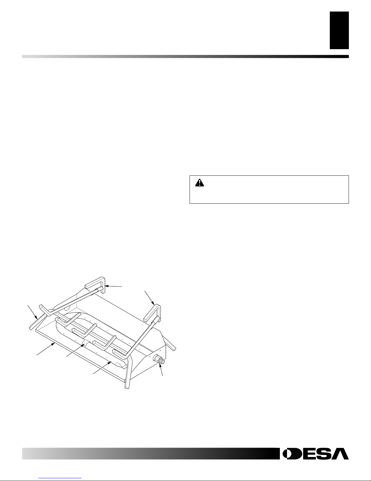
PRODUCT IDENTIFICATION
Grate Steps
Grate
Burner
Pan
Figure 1 - Product Identification (Dual Burner Shown)
Hearth Kit Model _________________________
Serial Number ___________________________
Log Set Model ___________________________
Burner
Clamp
Burner
Manifold
Burner Inlet
Fitting
OPTIONAL PRODUCT
FEATURES
ON/OFF SAFETY VALVE/PILOT KIT AND
PROPANE/LP CONVERSION
An optional valve/safety pilot kit with a piezo ignitor is available for
this appliance. This system requires no matches, batteries, or other
sources to light. You must use this optional system for LP conversion. See Accessories, page 15.
REMOTE CONTROL READY (MILLIVOLT)
SAFETY VALVE/PILOT KIT
An optional millivolt valve/safety pilot kit with a piezo ignitor is
available for this appliance. This system requires no matches, batteries,
or other sources to light. This system may be connected to a wall switch
or hand-held wireless remote control. See Accessories, page 15.
REMOTE CONTROL ACCESSORIES
There is an optional hand-held ON/OFF remote control that can be
purchased separately for this log set. You must use the millivolt
valve/safety pilot kit to use remote accessories with this appliance.
See Accessories, page 15.
A wall switch is also available for this appliance. You must use the
millivolt valve/safety pilot kit to use the wall switch with this
appliance. See Accessories, page 15.
For more information, visit www.desatech.com
For more information, visit www.desatech.com
901265-01K
INSTALLATION
4
Flue Opening Specifications
Check Gas Type
Venting Specifications for Installation
INSTALLATION
CAUTION: Do not remove the data plates attached
to the burner pan. The data plates contain important
warranty information.
WARNING: Before installing in a solid fuel burning
fireplace, the chimney flue and firebox must be cleaned
of soot, creosote, ashes and loose paint by a qualified
chimney cleaner. Creosote will ignite if highly heated.
A dirty chimney flue may create and distribute soot
within the house. Inspect chimney flue for damage. If
damaged, repair flue before operating heater.
NOTICE: Installation, service, and repair of this appliance must be performed by a qualified installer,
service agency, company or gas supplier experienced with this type of gas appliance. Only factory
authorized components listed in these instructions
may be used in accordance with the manufacturer’s
instructions and all codes and requirements of the
authority having jurisdiction. Any modifications to
this kit, or use of unauthorized components or accessory items will void the manufacturer’s warranty, and
may result in a hazardous condition.
FLUE OPENING SPECIFICATIONS
Note:
This vented appliance must be installed only in a solid-fuel
burning fireplace with a working flue and constructed of noncombustible material.
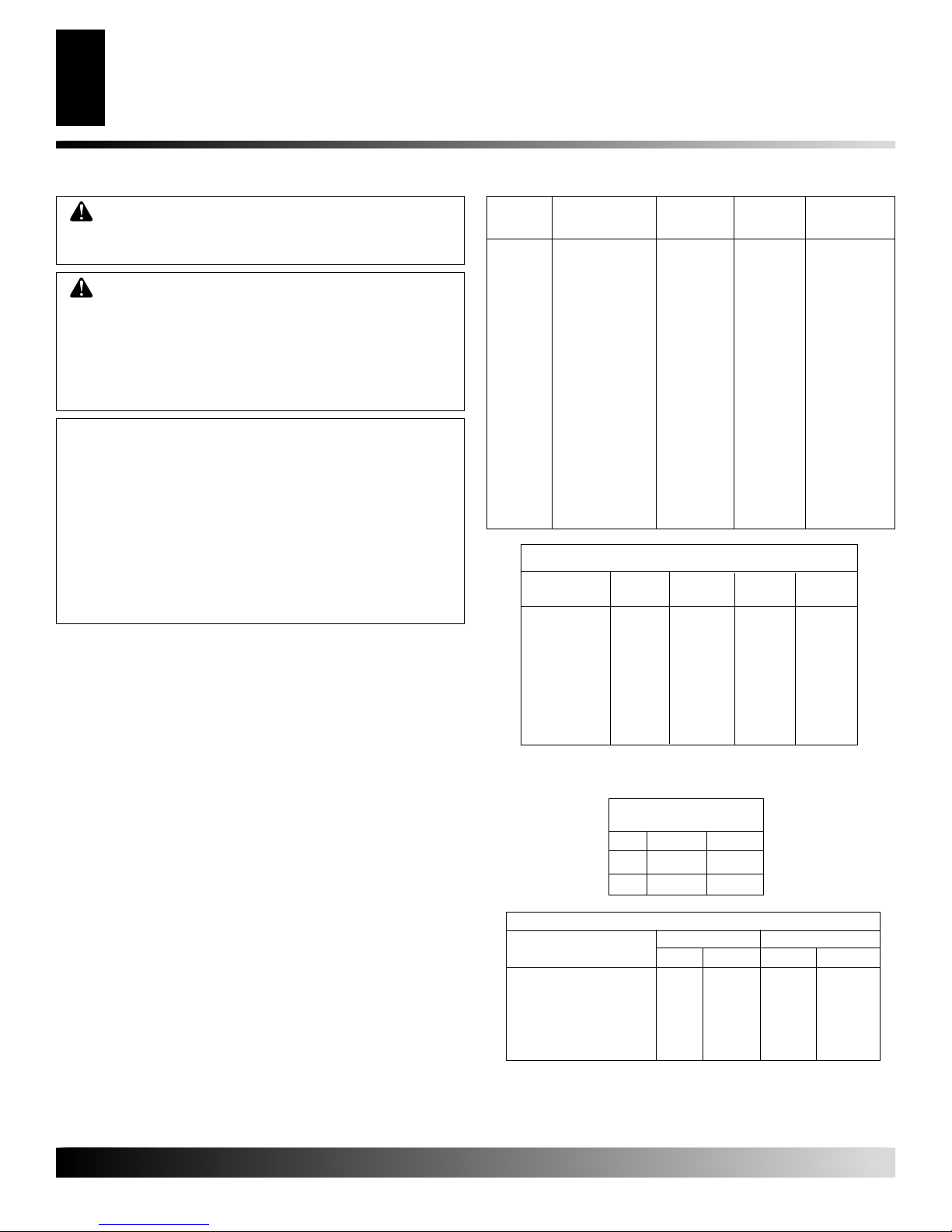
The charts in Figure 2 indicate technical information regarding the
installation of your gas log set. Please make sure that all of the
specifications shown are applicable before installation is attempted.
The fireplace must include a working flue and venting system with
the minimum openings shown in the Figure 2.
CHECK GAS TYPE
Use only natural gas. If your gas supply is not natural gas, you must
install ON/OFF Safety Valve/Pilot Kit (see Accessories, page 15).
Call dealer where you bought log set.
If the fireplace does not have a gas supply shutoff valve, one must
be installed.
VENTING SPECIFICATIONS FOR
INSTALLATION
The fireplace chimney flue and vent must be drafting properly. To
check the vent for proper drafting: Light a tightly rolled newspaper
on one end and place it at the inside front edge of the fireplace.
Observe the smoke and be sure the vent is properly drawing it up the
chimney. If the smoke spills out into the room, extinguish the flame
and remove any obstruction until proper venting is achieved.
The chimney flue must remain open a minimum of 3" at all times
during the operation of this log set.
MODEL DESCRIPTION
BURNER
VVSR18 18" Single 50,000 40,000 8" dia.
FVSR18
VVSR24 24" Single 60,000 50,000 8" dia.
FVSR24
VVDR18 18" Dual 55,000 45,000 8" dia.
FVDR18
MD18
VVDR24 24" Dual 65,000 55,000 8" dia.
FVDR24
MD24
VVDR30 30" Dual 70,000 60,000 8" dia.
FVDR30
LBFL18 18" Triple 65,000 55,000 8" dia.
BFLT18
LBFL24 24" Triple 70,000 60,000 8" dia.
BFLT24
MINIMUM FIREBOX SIZES
FRONT BACK
MODEL WIDTH* WIDTH** DEPTH HEIGHT
18DR/SR 28" 16" 14" 18"
MD18
24DR/SR 29 3/4" 17" 15 1/2" 18"
MD24
30DR 36" 27" 18" 18"
BFL18 28" 16" 15 1/2" 18"
BFL24 30" 22" 15 1/2" 18"
*Add 6" if safety valve/pilot is used
**At depth indicated
FUEL INLET PRESSURE
SPECIFICATIONS (W.C.)
NG 5.5" 10.5"
LP 11" 13"
LOG NATURAL PROPANE/LP
SIZE IN. NUM. IN. NUM.
18SR/DR .120 31 .073 49
MD18/18SR/DR
24SR/DR/BFL18 .129 30 .086 44
MD24/24SR/DR/BFL18
30DR/BFL24 .1405 28 .089 43
Btu Input
Natural Gas
Min. Max.
BURNER ORIFICE
Btu Input
Propane/LP
Gas
Minimum
Vent Opening
Figure 2 - Technical Information Charts
For more information, visit www.desatech.com
For more information, visit www.desatech.com
901265-01K
INSTALLATION
Continued
Installing Damper Clamp
INSTALLATION
Connecting to Gas Supply
5
5
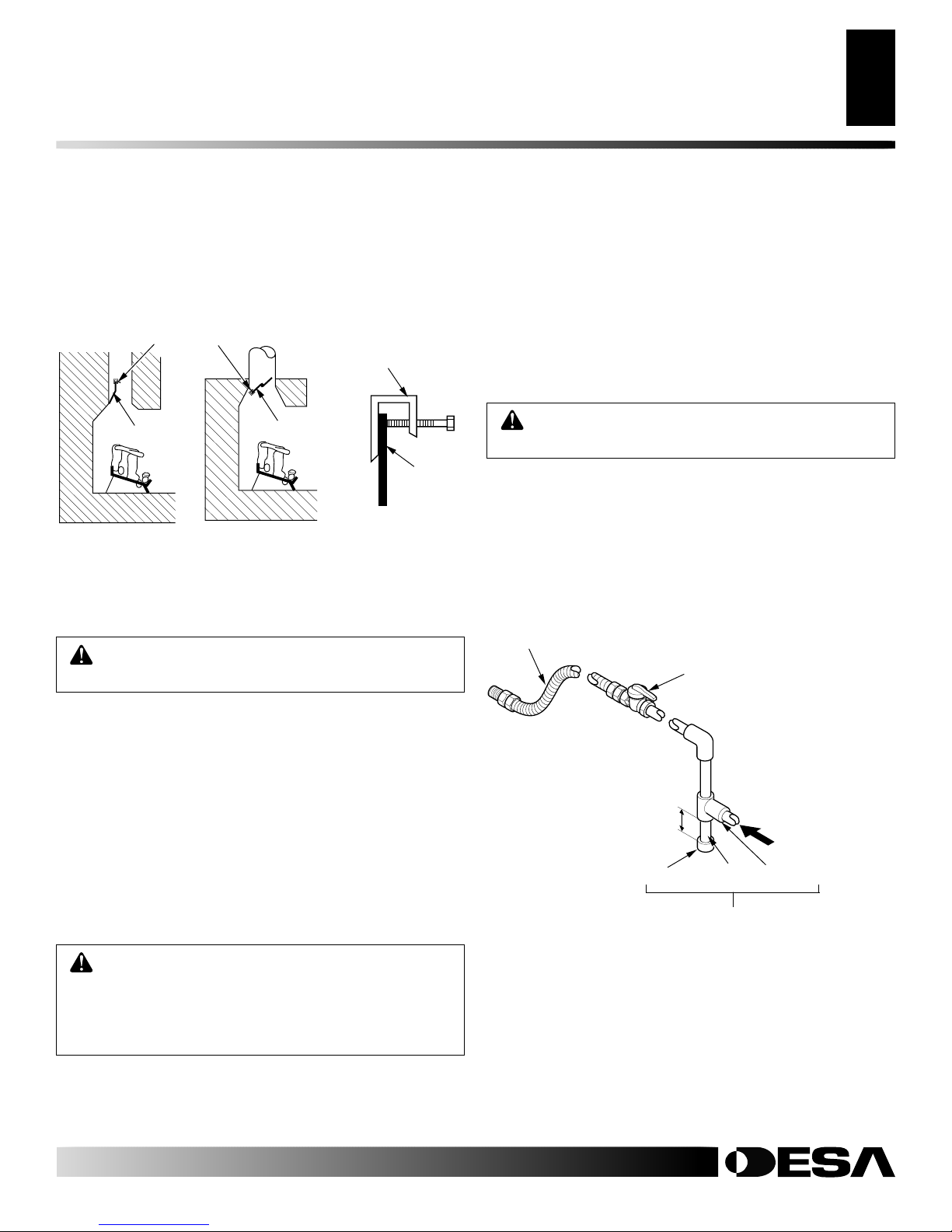
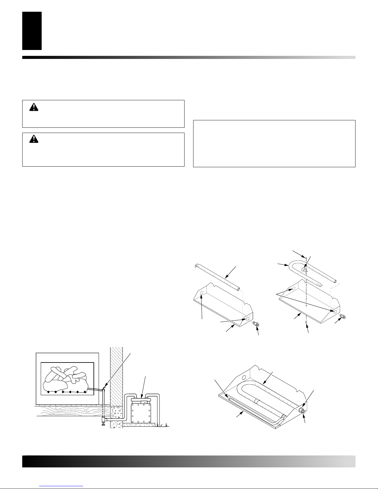
INSTALLING DAMPER CLAMP
Secure the damper stop clamp provided to the leading edge of the
damper as shown in Figure 3. If for any reason this clamp doesn't
work on your fireplace, another suitable clamp or permanent stop
must be installed, or the damper blade must be cut or removed.
Damper Clamp
Damper
Masonry Fireplace
Figure 3 - Attaching Damper Clamp
Manufactured
Fireplace
Damper
Damper
Clamp
Damper
CONNECTING TO GAS SUPPLY
WARNING: A qualified service person must connect log set to gas supply. Follow all local codes.
Installation Items Needed
Before installing log set, make sure you have the items listed below.
• piping (check local codes)
• sealant (resistant to Propane/LP gas)
• equipment shutoff valve
• test gauge connection
• adjustable (crescent) wrench or pliers
• sediment trap
• tee joint
• pipe wrench
Installation must include a equipment shutoff valve, union, and
plugged 1/8" NPT tap. Locate NPT tap within reach for test gauge
hook up. NPT tap must be upstream from log set (see Figure 4).
IMPORTANT:
Install equipment shutoff valve in an accessible
location. The equipment shutoff valve is for turning on or shutting
off the gas to the appliance.
Apply pipe joint sealant lightly to male NPT threads. This will
prevent excess sealant from going into pipe. Excess sealant in pipe
could result in a clogged burner injector.
WARNING: Use pipe joint sealant that is resistant
to liquid petroleum (LP) gas.
We recommend that you install a sediment trap in supply line as
shown in Figure 4. Locate sediment trap where it is within reach for
cleaning. Install in piping system between fuel supply and heater.
Locate sediment trap where trapped matter is not likely to freeze. A
sediment trap traps moisture and contaminants. This keeps them
from going into log set controls. If sediment trap is not installed or
is installed wrong, log set may not run properly.
Approved Flexible Gas Hose
(if allowed by local codes)
CSA Design-Certified
Equipment Shutoff
Valve With 1/8" NPT
Tap*
3" Minimum
Cap
Figure 4 - Gas Connection
Pipe Nipple
Sediment Trap
From Gas Meter
(5" W.C.** to 10.5"
W.C. Pressure)
Tee Joint
CAUTION: Use only new, black iron or steel pipe.
Internally-tinned copper tubing may be used in certain
areas. Check your local codes. Use pipe of 1/2" diameter or greater to allow proper gas volume to log set. If
pipe is too small, undue loss of volume will occur.
For more information, visit www.desatech.com
For more information, visit www.desatech.com
901265-01K
* Purchase the optional CSA design-certified equipment shutoff
valve from your dealer. See Accessories, page 15.
** Minimum inlet pressure for purpose of input adjustment.
INSTALLATION
6
Checking Gas Connections
Hearth Kit Assembly and Installation
INSTALLATION
Continued
CHECKING GAS CONNECTIONS
WARNING: Test all gas piping and connections,
internal and external to unit, for leaks after installing
or servicing. Correct all leaks at once.
WARNING: Never use an open flame to check for
a leak. Apply a noncorrosive leak detection fluid to
all joints. Bubbles forming show a leak. Correct all
leaks at once.
Pressure Testing Gas Supply Piping System
Test Pressures In Excess Of 1/2 PSIG (3.5 kPa)
1. Disconnect log set and its individual equipment shutoff valve
from gas supply piping system.
2. Cap off open end of gas pipe where equipment shutoff valve
was connected.
3. Pressurize supply piping system by either using compressed
air or opening main gas valve located on or near gas meter.
4. Check all joints of gas supply piping system. Apply noncorrosive
leak detection fluid to gas joints. Bubbles forming show a leak.
5. Correct all leaks at once.
6. Reconnect log set and equipment shutoff valve to gas supply.
Check reconnected fittings for leaks.
Test Pressures Equal To or Less Than 1/2 PSIG (3.5 kPa)
1. Close equipment shutoff valve (see Figure 5).
2. Pressurize supply piping system by either using compressed
air or opening main gas valve located on or near gas meter.
3. Check all joints from gas meter to equipment shutoff valve
(see Figure 5). Apply noncorrosive leak detection fluid to gas
joints. Bubbles forming show a leak.
4. Correct all leaks at once.
Equipment
Shutoff Valve
Gas Meter
HEARTH KIT ASSEMBLY AND INSTALLATION
Kit Assembly - Single and Dual-Flame Only
1. Determine which side the gas line will be coming into the fireplace.
NOTICE: Triple-burner models CBL18/24 or BFLT18/24
come preassembled with gas inlet on right side of
burner pan. DO NOT attempt to reposition burner on
triple-burner models. If your fireplace supply is on the
left side, a longer 3/8" flex line should be purchased and
routed behind burner pan and away from flame area.
2. Using a hammer and screw driver, remove knockout plug from
the side of the pan that corresponds to the gas line (see Figure 6).
3. Unscrew burner inlet fitting from burner manifold.
4. Place burner manifold in pan with threaded opening facing
open knockout plug.
5. Using thread sealant (resistant to the action of propane/LP
gas) on larger end of fitting, screw the burner inlet fitting
through hole and into burner manifold (see Figure 6). Tighten
using a wrench. If using propane/LP gas, see Propane/LP
Gas Conversion, page 8.
Nut
Burner Manifold
Knockout
Plugs
Knockout
Plugs
Burner Pan
(Front)
SINGLE-BURNER DUAL-FLAME
Front Burner
Burner Pan
(Front)
Burner Inlet
Fitting
Burner
Manifold
Burner Clamp
Burner Inlet
Screw
Fitting
Gas Connection
Must Be On Right
Side For Triple
Burner
Figure 5 - Checking Gas Joints
For more information, visit www.desatech.com
For more information, visit www.desatech.com
Burner Pan
(Front)
TRIPLE-BURNER
Figure 6 - Installing Burner
Burner Inlet
Fitting
901265-01K
INSTALLATION
Continued
Hearth Kit Assembly and Installation (Cont.)
INSTALLATION
Optional GA9050A ON/OFF Safety Valve/Pilot Kit Assembly
7
7
6. Using burner clamp, screw , and nut provided, assemble clamp
to pan (“U” style and triple burners only). This will hold the
burner manifold in place.
7. If using optional GA9050A kit, go to Optional GA9050A On/
Off Safety Valve/Pilot Kit section for installation instructions.
If using optional GA9150A kit, follow instructions included
with kit for installation and operation.
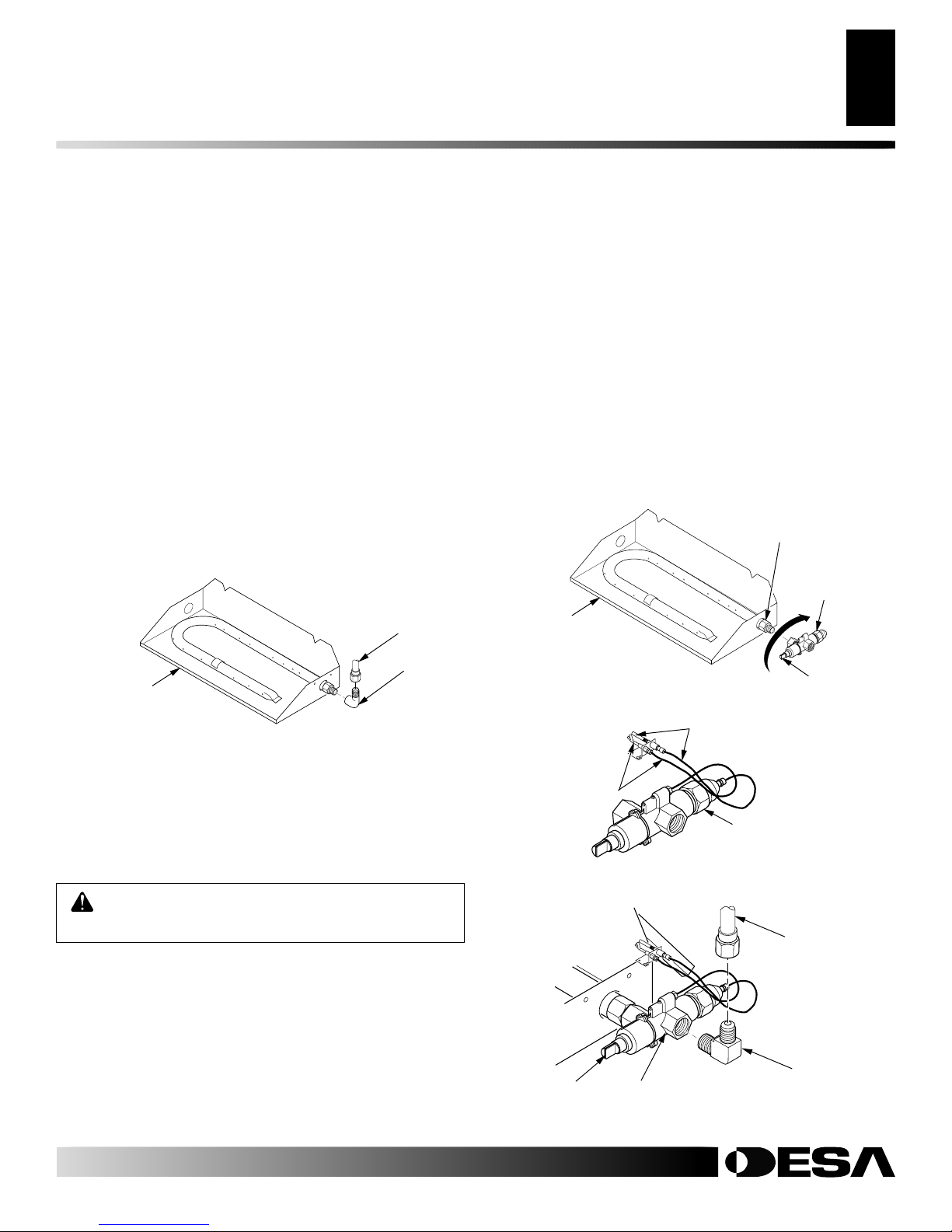
Installation and Gas Connection
1. Place the burner pan assembly in the center of the fireplace
floor. Make sure the front of pan faces forward.
2. Thread the gas supply fitting to the fireplace gas supply pipe.
Use thread sealant.
3. Install adapter fitting onto the burner inlet fitting using
thread sealant on male threads of burner inlet fitting (see
Figure 7). Adjust to most convenient position.
4. Install the gas connector tube to the gas supply fitting. Carefully shape tube to attach to adapter fitting. Be careful not to
cause kinks in tube.
Gas Connector
Burner Pan
Assembly (Facing
Front of Fireplace)
Figure 7 - Connecting Gas to Appliance
Tube
Adapter
Fitting
3. Install the inlet fitting into the inlet opening of the gas control
valve (see Figure 10). Use thread sealant on the male pipe
threads.
4. Place the burner pan assembly in the center of the fireplace
floor. Make sure the front of pan faces forward.
5. Thread the gas supply fitting to the fireplace gas supply pipe.
Adjust to most convenient position.
6.
Install the gas connector tube t o the gas supply fitting. Carefully
shape tube to attach to adapter fitting. Be careful not to cause
kinks in tube.
7. Test for leaks following instructions under Testing Burner for
Leaks, page 9.
8.
Retighten and adjust the location of the gas control as necessary .
The gas control should be level, with the control rod to the front.
Burner Inlet Fitting
Gas Control
Valve
Burner Pan
Assembly
Figure 8 - Installing Gas Control Valve
Thermocouple and Line
Control Rod
OPTIONAL GA9050A ON/OFF SAFETY
VALVE/PILOT KIT ASSEMBLY
For additional convenience and safety, or for propane/LP conversion, an optional ON/OFF safety valve/pilot kit is available. See
Accessories, page 15.
WARNING: You must use a ON/OFF safety valve/
pilot kit for propane/LP conversion.
Natural Gas Installation
1. Thread the gas control valve onto the burner inlet fitting (see
Figure 8). Use thread sealant on the male threads of the burner
inlet fitting. Hold the burner inlet fitting with a wrench to prevent overtightening the connection to the burner. Make sure
the control rod is facing the front (see Figure 8).
2. Attach the pilot gas line to the pilot outlet of the gas control valve
and tighten. Connect the thermocouple to the rear of the gas control valve. See Figure 9. Do not overtighten. If using propane/LP
gas, see Changing Pilot Orifice, page 8.
For more information, visit www.desatech.com
For more information, visit www.desatech.com
901265-01K
Pilot and Line
Gas Control Valve
Figure 9 - Gas Control Valve with Thermocouple and Pilot
Gas
Connector
Tube
Gas Inlet
Gas Control
Valve
Figure 10 - Installing Inlet Fitting and Gas Connector Tube
Inlet
Opening
Fitting
INSTALLATION
8
Optional GA9050A ON/OFF Safety Valve/Pilot Kit Assembly (Cont.)
INSTALLATION
Continued
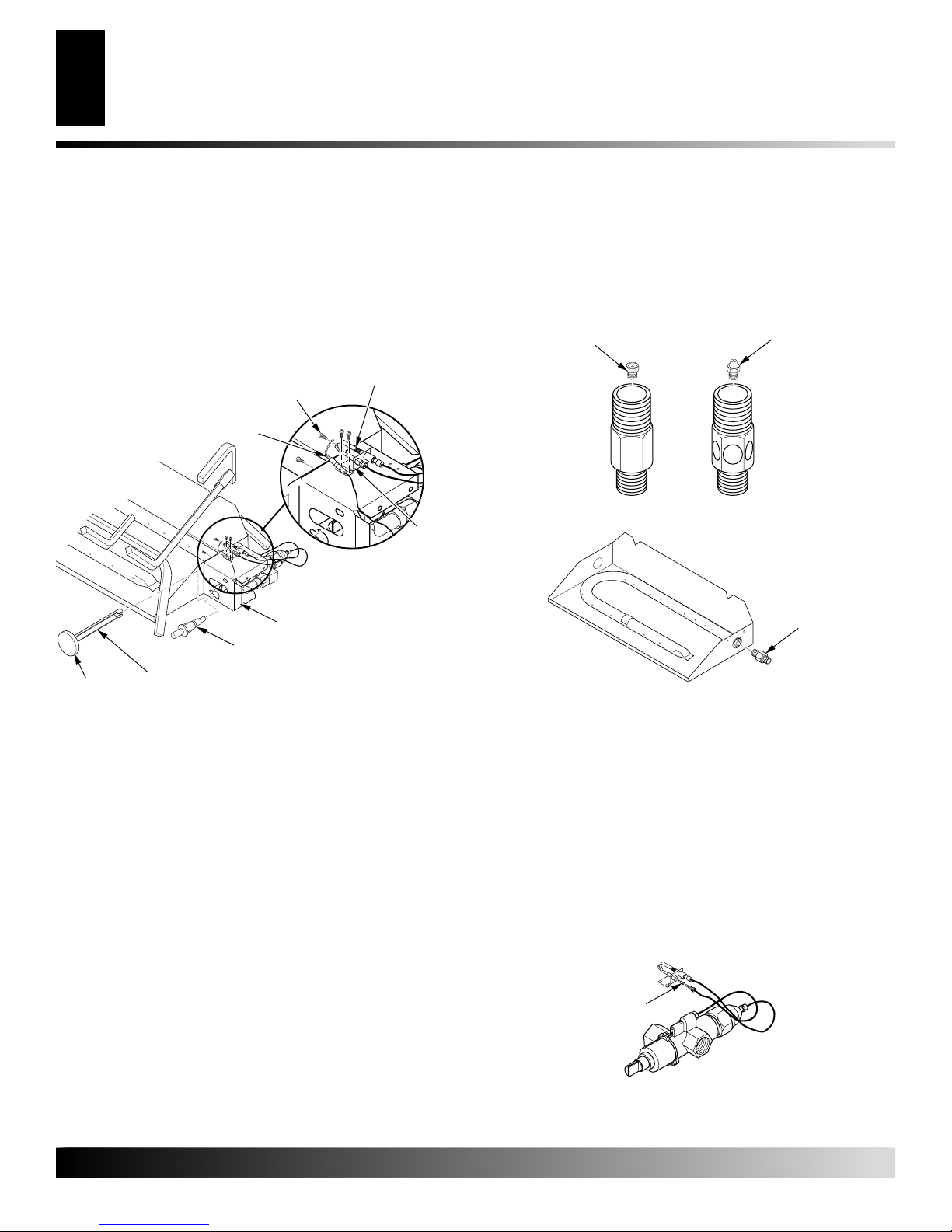
9. Install cover to burner pan using screws provided.
10. Install thermocouple, pilot, and ignitor onto valve cover as
shown in Figure 11. Use the provided screws.
11. Push the control rod extension onto the “D” shaped control
rod through the center hole in the cover.
12. Install the position decal and control knob making sure to align
the marks with the correct stop positions of the gas control.
Screw
Ignitor
Valve Cover
Piezo Ignitor
Control Rod
Control
Knob
Figure 11 - Installing Cover, Control Knob, and Piezo Ignitor
Extension
Thermocouple
Pilot
Propane/LP Gas Conversion
To convert to propane/LP gas, the burner inlet fitting and pilot orifice
must be replaced. The propane/LP burner inlet fitting is supplied with
the orifice installed for a 24" log set. If you have an 18" or 30" set, you
must change this orifice also. See Figure 1, page 3 for product
identification.
Burner Inlet Fitting
1. Remove the burner inlet fitting from the burner pan assembly.
DO NOT remove the orifice from this fitting. The propane/LP
burner inlet fitting is included in the hardware kit (see Figure 12).
2. Be sure to use the correct orifice for your appliance. The hardware kit included with this appliance contains two orifices with
a cone-like shape. If you have an 18" set, the orifice for the
burner inlet fitting is red; for a 30" set, it is black. If you have
a 24" log set, the orifice is already installed inside the fitting.
3. For an 18" or 30" set, use a 10mm socket or nut driver to remove the orifice from the propane/LP burner inlet fitting.
Choose the correct orifice for your log set size and install in
place of the orifice you just removed.
4. Using thread sealant (resistant to the action of propane/LP gas) on
larger end of fitting, screw the burner inlet fitting through hole
and into burner manifold (see Figure 13). Tighten using a wrench.
5 . Follow steps 1 through 12 under Natural Gas Installation, pages
7 and 8.
Injector for
Natural Gas
NATURAL
GAS FITTING
Figure 12 - Burner Inlet Fittings with Injectors
Figure 13 - Remove Burner Inlet Fitting
Injector for
Propane/LP Gas
PROPANE/LP
GAS FITTING
Burner Inlet
Fitting for
Natural Gas
Changing Pilot Orifice
The pilot is provided with a natural gas orifice installed. For
propane/LP gas you must remove it and replace it with an propane/
LP orifice. The accessory hardware kit contains an propane/LP
orifice with a red stripe for converting the pilot.
1. Gently loosen and remove the pilot line connection from the
bracket (see Figure 14).
2. Replace the injector (see Figure 14) with the propane/LP pilot
injector with the red stripe.
3. Replace and tighten the pilot line to the bracket.
4. Continue with step 3 under Natural Gas Installation, pages 7
and 8.
Pilot Injector
Figure 14 - Installing Propane/LP Pilot Orifice
For more information, visit www.desatech.com
For more information, visit www.desatech.com
901265-01K
INSTALLATION
Continued
Testing Burner for Leaks
INSTALLATION
Adding Pan Material
Installing the Grate and Logs
9
9
TESTING BURNER FOR LEAKS
1. Generously apply noncorrosive leak detection fluid to all
connections.
WARNING: Never check for gas leaks with
open flame.
2. Light the burner with the shutoff valve no more than half open
and holding a match slightly in front of the pan (see Lighting
Instructions, page 10).
3. Inspect all connections for bubbles, raw gas odor, or flame
from any area other than the burner (leaks). If leaks are detected, shut off the gas valve immediately. Tighten, or reassemble the loose connection(s) using pipe joint compound until
burner system is leak free.
4. When the burner is tested and leak free, observe the individual
tongues of flame on the burner.
cludes more ports on the outside of the bar. Make sure that all
ports are clear and producing flame evenly across the burner. If
any ports appear blocked, clear them by removing the burner
manifold and reaming the ports with a modified paper clip or
other suitable tool.
5. When finished testing, turn the gas shutoff valve OFF to extinguish all flames.
Note:
The burner design in-
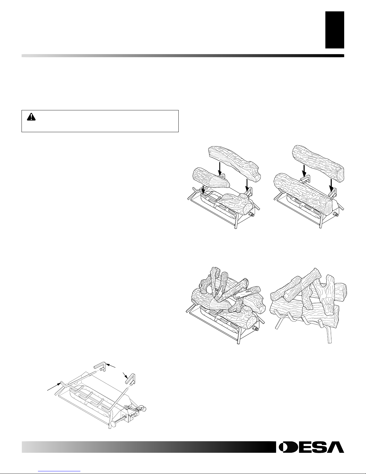
ADDING PAN MATERIAL
1. Open the bag of ash bed material (vermiculite) and spread it
evenly across the burner pan to the top. You may overflow the
front and sides of the pan to cover the entire pan and connecting hardware. Do not cover GA9050A or GA9150A valve.
2. Open the glowing embers and evenly cover the ash bed material (vermiculite) in the burner pan.
3. Place the back log on the grate onto the grate steps (see
Figure 16).
4. Place the front log(s) on the grate and slide forward against
the front bars on the grate (see Figure 16).
5. Place the smaller top logs onto the bottom logs (see Figure 17).
Leave as much open space between logs as possible to minimize flame impingement and sooting.
they are handled roughly or if hit together while being placed.
Kingston Split Oak Logs
Figure 16 - Installing Front and Back Logs (Number and style of
your logs may vary)
Note:
Logs may chip if
Hanover Round Oak Logs
INSTALLING THE GRATE AND LOGS
1. Place the grate over the burner pan where the two outer horizontal supports on the grate fit into the two pan positioning
notches in the rear vertical edge of the pan.
2. Slide the two rear log grate steps over the two outer horizontal
supports on the grate as shown in Figure 15.
Grate Steps
Grate
Figure 15 - Installing Grate (Pan Material Not Shown)
For more information, visit www.desatech.com
For more information, visit www.desatech.com
901265-01K
Kingston Split Oak Logs Malibu Drift Logs
Figure 17 - Placement of Top Logs
OPERATING APPLIANCE
10
For Your Safety Read Before Lighting
Lighting Instructions
Gas Shutoff Valve Operation
Curing Logs
Operating Instructions for GA9050A
OPERATING APPLIANCE
FOR YOUR SAFETY
READ BEFORE LIGHTING
WARNING: Keep flue open when operating unit.
WARNING: If you do not follow these instructions
exactly, a fire or explosion may result causing property damage, personal injury or loss of life.
BEFORE LIGHTING smell all around the appliance area for
gas. Be sure to smell next to the floor because some gas is heavier
than air and will settle on the floor.
WHAT TO DO IF YOU SMELL GAS
• Do not try to light any appliance.
• Do not touch any electric switch; do not use any phone in
your building.
• Immediately call your gas supplier from a neighbor’ s phone.
Follow the gas supplier’s instructions.
• If you cannot reach your gas supplier, call the fire department.
LIGHTING
INSTRUCTIONS
1. STOP! Read the safety information, above.
2. Turn the gas shutoff valve to OFF.
3. W ait f ive (5) min utes to clear out any gas. If you then smell
gas STOP! Follow the safety inf ormation above. If you don't
smell gas, go on to the next step.
4. Light a match and lay it on top of the pan material about
2" from the end of the supply side of the pan
5. Slowly turn the gas shutoff valve ON until the burner ig-
nites. If the burner doesn’t ignite within 10 seconds with
the match burning, turn the shutoff v alv e OFF and r epeat
steps 1 through 4 again.
CURING
LOGS
During the 2-3 hour appliance break-in period, you may detect
an odor from the appliance as the various paints and compounds used in the manufacturing of this log set cure. This is a
normal and temporary situation that is not cause for alarm.
However, you may want to provide extra ventilation to the room
during this time.
To ensure proper curing of the logs:
• Ignite a 2" flame and maintain it for 1 hour.
• Burn the logs in consecutive 1 hour periods raising the flame
an additional 2" to full flame height for a total of three hours.
OPERATING INSTRUCTIONS
FOR GA9050A
Note:
Operation instructions for GA9150A Remote Ready
Valve/Pilot Kit will be included with the kit.
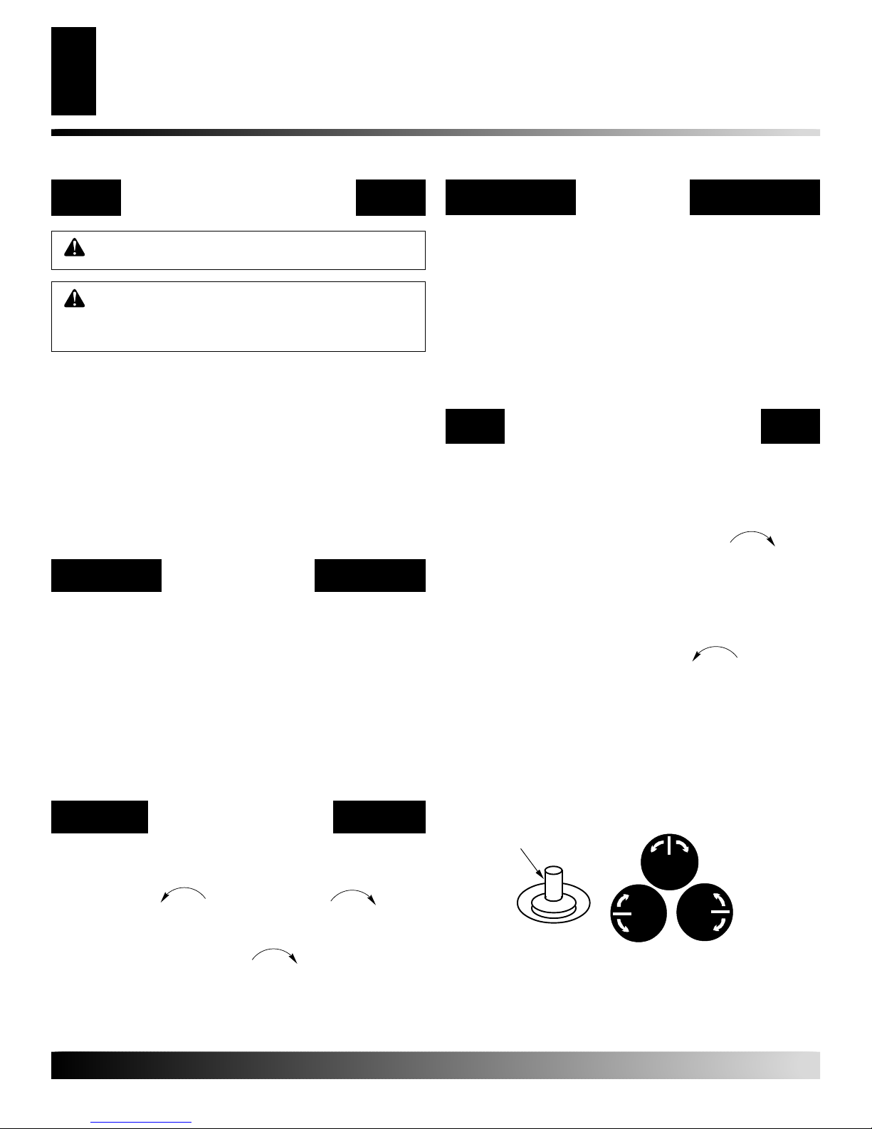
1. STOP! Read the safety inf ormation, column one this page.
2. Make sure equipment shutoff valve is fully open.
3. Press in and turn control knob clockwise to the
OFF position.
4. Wait five (5) minutes to clear out any gas. Then smell for
gas around log set and near floor. If you smell gas, STOP!
Refer to the National Fuel Gas Codes, ANSI Z233.1/NFPA
54, Section 5.3, Air for Combustion and Ventilation. If you
don’t smell gas, go to the next step.
5. T urn control knob counter clockwise to the PILOT
position and press in. Keep control knob pr essed in for f ive
(5) seconds.
Note:
You may be running this log set for the first time
after hooking up to gas supply . If so, the control knob may
need to be pressed in for 30 seconds. This will allow air to
bleed from the gas system.
• If contr ol knob does not pop up when released, contact a
qualified service person or gas supplier for repairs.
GAS SHUTOFF
VALVE OPERATION
Flame Adjustment
Adjust the flame ON/OFF by turning the gas shutoff valve
counterclockwise to open or clockwise to close,
as necessary.
Shutting Off Appliance
Turn gas shutoff valve clockwise to the OFF position.
For more information, visit www.desatech.com
For more information, visit www.desatech.com
Control Knob
Pilot
Ignitor
ON
FROM "PILOT" POSITION
SLIGHT PUSH TO
On
PULL PUSH
TURN OFF
PULL PUSH
SLIGHT PUSH TO
FROM "PILOT" POSITION
ON OFF
Figure 18 - Ignitor and Control Knob
TURN OFF
OFF
FROM "PILOT" POSITION
SLIGHT PUSH TO
PULL PUSH
TURN OFF
Off
ON
OFF
901265-01K
 Loading...