

Desa GW30B, GW30PB, GWB30PB, GWB30B Installation Instructions Manual
GW30PB, GWB30PB
GRAVITY DIRECT VENT WALL FURNACE
INSTALLATION INSTRUCTIONS
GW30B, GWB30B
SAVE THIS BOOK
This book is valuable. In addition to instructing you on how to install and maintain your appliance, it also contains information that will
enable you to obtain replacement parts or accessory items when needed. Keep it with your other important papers.
G
I
S
E
N
D
C
E
D
R
E
I
T
F
WARNING: This Gravity Direct Vent Wall Furnace Series is intended for use with natural or propane gas only (depending on the
type of gas your particular model is approved for), do not attempt to burn any solid fuels in this fireplace.
I
DESA INTERNATIONAL
2701 INDUSTRIAL DRIVE P/N 55328
P.O. BOX 90024 REV B
BOWLING GREEN, KY 42101-9004 6/02
www.desatech.com
CONTENTS
1. INTRODUCTION PG. 2
2. MINIMUM DIMENSION PG. 2
3. MINIMUM CLEARANCES PG. 3
4. MANTEL CLEARANCES PG. 3
5. TOGGLE SWITCH PG. 4
5. GAS SUPPLY TESTING & HOOK-UP PG. 5
6. SURROUND ASSEMBLY PG. 6
8. PILOT ADJUSTMENT PG. 7
9. GLASS PANEL REMOVAL PG. 7-8
11. LOG INSTALLATION PG. 8
12. BURNER FLAME ADJUSTMENT PG. 8
13. TERMINATION CAP PG. 9
14. TRANSITION BOX PG. 9
15. WIRING DIAGRAM PG. 10
16. LIGHTING INSTRUCTIONS PG. 11
17. TROUBLESHOOTING PG. 12
18. ACCESSORY PARTS LIST PG. 13
19. LIMITED WARRANTY PG. 14
- 1 - For more information, visit www.desatech.com
r
d
n
N
r
d
• Do not store or use gasoline or any other flammable
vapors or liquids in the vicinity of this or any othe
appliance.
• Due to high temperatures, the appliance should be
located out of traffic and away from furniture an
draperies.
• Do not place clothing or other flammable materials o
or near the appliance.
EVER leave children unattended when a fire is
•
burning in the fireplace.
WHAT TO DO IF YOU SMELL GAS
• Do not try to light any appliance.
• Do not touch any electrical switch.
• Do not use any phone in your building.
• Immediately call your gas supplier from a neighbor’s
phone. Follow the gas supplier’s instructions.
• If you cannot reach your gas supplier, call the fire
department.
WARNING: Improper installation, adjustment,
alteration, service or maintenance can cause injury,
property damage, or loss of life. Refer to this manual fo
assistance or additional information. Consult a qualifie
installer or local distributor.
CHECK LOCAL CODES BEFORE
INSTALLING THIS FIREPLACE.
FOR YOUR SAFETY
FOR YOUR SAFETY
INTRODUCTION
Models GW30B/GW30PB series are gravity direct vent wall
furnace inserts with a sealed combustion chamber that uses
millivolt gas control valve and millivolt ignition system.
The system requires a unique termination that includes
transition pipes. The flex pipe must be installed only in
masonry or listed factory built chimney.
If you are uncertain as to what gas your unit is equipped for,
please check the rating plate located in the interior of the
appliance opening or consult your local distributor of DESA
products.
BEFORE BEGINNING THE INSTALLATION OF THE
FIREPLACE, READ THESE INSTRUCTIONS THROUGH,
COMPLETELY.
♦ This DESA fireplace and its components are safe
when installed according to this installation manual.
Unless you use DESA components, which has been
designed and tested for this appliance, you may cause
a fire hazard.
♦ The DESA warranty will be voided by and DESA
disclaims any responsibility for the following actions:
a) Modification of the fireplace, components, doors, blower,
fans, air inlet system and damper control.
b) Use of any component part not manufactured or approved
by DESA in combination with a DESA fireplace system.
When installed on site in a Manufactured Home (mobile
home) installation must conform with the Manufactured Home
Construction and Safety Standard, Title 24 CFR, Part 3280 or
when such a standard is not applicable, the Standard for
Manufactured Home Installation, ANSI A225.1/NFPA 501A.
This appliance, when installed, must be electrically grounded
in accordance with local codes, or in the absence of local
codes, with the National Electrical Code, ANSI/NFPA 701987 and CSA C22.2 Canadian Electrical Code for Canada.
The installation must conform to local codes, or in the
absence of local codes, with the National Fuel Gas Code ANSI
Z223.1-1992 (CAN B149. IN CANADA)
This appliance complies with ANSI Z21.44-1995, and CAN1
2.19-M81, IR #41 and #55 as a gravity direct vent wall
furnace.
THIS APPLIANCE MAY BE USED AS A PRIMARY
SOURCE OF HEAT.
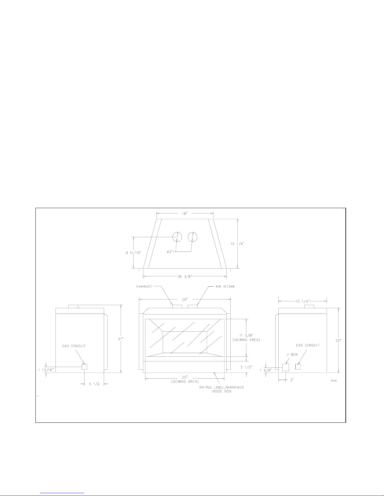
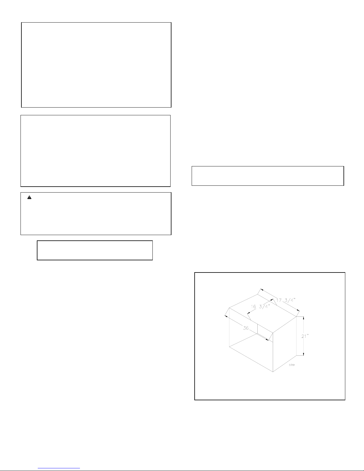
MINIMUM INSIDE FIREPLACE DIMENSIONS
The minimum inside dimensions of a masonry or listed factory
built fireplace are as follows:
• Front Width ………………………… 36”
• Back Width ………………………… 17 ¾ “
• Depth ………………………… 16 ¾ “
• Height ………………………… 21”
MINIMUM CHIMNEY SIZE
If the insert is installed in a masonry fireplace, the dimensions
of the chimney must be a minimum of 7 1/8 “ x 4”.
INSIDE DIMENSION
-2 - For more information, visit www.desatech.com
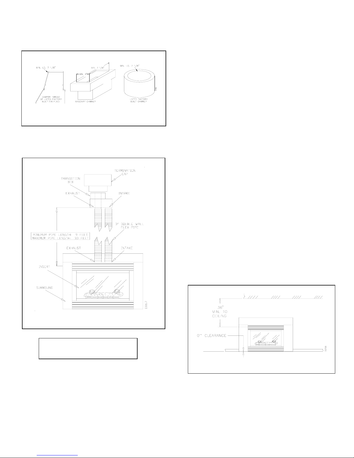
If the insert is installed in a listed factory built fireplace, the
dimensions of the factory built chimney must be a minimum
of 7 1/8 “ in diameter.
MINIMUM DIMENSIONS
NOTE: DAMPER THROAT OF THE CHIMNEY MUST
MEET THE MINIMUM DIMENSIONS SPECIFIED.
VENTING HEIGHT
Minimum venting height is 9 feet
Maximum venting height is 33 feet
To determine the safest and most efficient location for your
appliance, consider the following guidelines:
1. The location must allow for all the proper clearances (see
section on Clearances and Mantle Clearances).
2. Consider a location where the heat output would not be
affected by drafts, air conditioning ducts, windows, or doors.
3. This fireplace may be installed in bedrooms or
bathrooms in accordance with local codes.
ALSO, IN SELECTING A LOCATION, THE
FOLLOWING PRECAUTIONS MUST BE OBSERVED:
1. Due to high temperatures, do not locate this
appliance in high traffic areas or near furniture and
draperies.
2. Never obstruct the front opening of the appliance or the
flow of combustion and ventilation air. Keep control
compartments accessible.
3. Do not locate close to where gasoline or other flammable
liquids may be stored. The appliance must be kept clear
and free from combustible materials.
MINIMUM CLEARANCES TO COMBUSTIBLES
• Opposite wall -------------------------------- 36”
• Ceiling to top of insert----------------------- 36”
• Perpendicular wall from edge of glass ---- 9”
• Floor ------------------------------------------- 0”
MANTLE CLEARANCES
Woodwork, such as wood trims, mantles, and other
combustible materials projecting no more than 1-1/2 inches
(38mm) shall not be placed within 6 inches (152 mm) of the
top of the insert (Refer to the above figure). Combustible
material above and projecting more than 1-1/2 inches (38
mm) from the appliance's front face must not be placed less
the 12 inches (305 mm) from the opening of the appliance,
(ref. NFPA Standard 211 Sec.7-3.3.3).
CLEARANCES
-3 - For more information, visit www.desatech.com
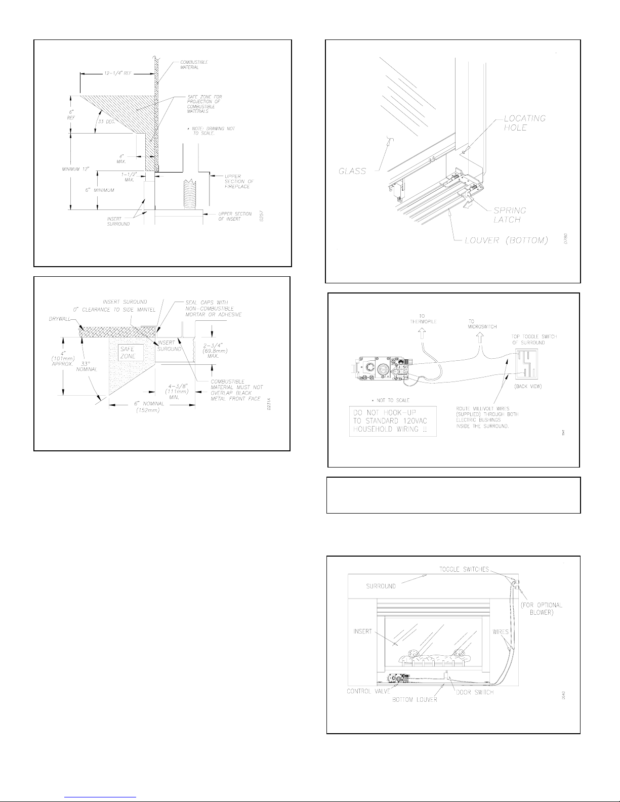
MANTEL CLEARANCE
TOP VIEW OF FIREPLACE
TOGGLE SWITCH CONNECTION
The installation of a toggle switch in this appliance allows you
to activate the gas control valve without the use of normal
household electricity. The valve operates on millivolt current
supplied by the heat generated from the sensor on the
thermopile. Refer to Surround Attachment for installing the
surround.
1. To swing down louver assembly. First pull on the upper
spring latches towards the inside of louver assembly. The
spring latches are located at each corner of the louver
assembly as shown in the preceding figure.
2. Connect the 18 GA. wires from the gas control valve to
the TOGGLE SWITCH located at the upper right corner
of the surround as shown in the figure below. (Wires and
toggle switches are supplied with the appliance).
3. The wires must be routed through the lower right side of
the insert, through both electric bushings of the insert (one
at the lower right side and the other towards the top), and
finally connected to the top toggle switch.
4. The bottom toggle switch is for the optional blower. The
wires for the blower are routed the same way as the wires
for the gas control valve. Refer to the wiring diagram on
page xx for connecting the wires to the blower.
BOTTOM LOUVER
GAS CONTROL VALVE
CAUTION: Do not wire this millivolt system wall switch
to a regular 120v AC wiring.
NOTE: If any of the original wire supplied must be replaced,
use type 18 AWG-105 deg. C (25 ft. length maximum) or
equivalent.
TOGGLE SWITCH LOCATION
-4 - For more information, visit www.desatech.com
 Loading...