


Contractor:
Manufacturer:
@
DENT-X
X-ray
Apparatus,
Dental,
DentalEZ
Field,
Hand
&
Held
Portable
Installation,
NSN
Operation
Number:
Contract:
Original
HDX
Intraoral
&
Maintenance
6525-01-425-5216
SP0200-00-D-8501
Document
Approved
Number
English
Language
353020
Version
X-ray
Lancaster,
Manual
PA
USA17601-5891

Table
of
Contents
Portable
HDX
Intraoral
X-ray
Section
Section
Section
Section
Section
Section
Section
Section
Section
Section X O
Section
Section
Section
I
Il
IT
IV
Unpacking
Tubehead & Cone
Tools
Assembly
V
Preliminary
Calibration
Calibration
VI
Turning System
VII
VII
General
Darkroom
IX
XI
Troubleshooting
Block
Wiring
Parts
XII
XIII
Limited
Introduction
Certification & Records
Statements
Installation...
Components
Required
Instructions
System
Checks
Checks
Operation.
Suggested
Darkroom
Recommendations
Common
Annual
User
Service
Maintenance
Diagram
Diagram,
Replacement
Parts
List
Specifications
Warranty
and
and
Symbols
Checks
ON & Self
and
for
kV
Exposure
Practices
Film
Problems
Maintenance
Information...
Service
Flow
Chart
Schematics
and
Cage
Product
Description..
....
Used
Calibration
and
mA
Diagnostics
Time
Settings:
and
Procedures
Program
Information
+
....
Speed
Group
“D” & “E”
iii
14
Installation,
Operation
and
Maintenance
Instructions
I

Section
This
manual
maintenance
HDX
Intraoral
only
be
performed
technician
dental
experienced
X-ray
I
Introduction
contains
instructions
X-ray
systems.
installation,
for
System.
by
in
an
the
DentalEZ®
These
procedures
maintenance
installing
operation,
Portable
service
and
servicing
and
should
Portable
Microcomputer
monitors
technique
HDX
Intraoral
and
factors
X-ray
and
precisely regulates
(kV,
DentalEZ
Features
specialized
mA,
and
exposure
circuitry
the
exposure
time)
5
that
WARNING:
This
AM
4B
Constant
The
conventional
up
patient
factors
observed.
After
Time
Procedures
Emission
HDX
to
30%
please
the
.
X-ray
unit
and
operator
and
operating
installing
review
Maintenance
Chart
and
with
Power
CEP™
Portable
X-rays
+
may
be
dangerous
unless
instructions
the
Portable
the
Operation
Section,
Darkroom
the
staff.
(CEP!M)
X-ray
as
illustrated.
to
safe
exposure
are
X-ray,
Section,
the
Exposure
Practices
Technology
emits
“Constant
and
continuously
potential dental
Compatible
line
Self-diagnostic
Up
and
by
.01
Very
*
Transportable.
during
an
X-ray
Conventional
voltage
down
second
short
exposure
machines
with a wide
conditions
control
arrows
increments
exposure
rather
can
X-ray
with
Alternating
range
panel
to
change
time
than
reduce
Normal
Current
of
120
time
in
bursts
radiation
70
KVp
Waveform
and
240
setting
as
dose
in
by
2
Voltage
“UUUUUU
Voltage
*
Compendium
DentalEZ
Time
Report,
Fig. 1 Comparison
Portable
May
HDX
1993,
Vol.
XIV,
Intraoral
No.
with
X-ray
5,
article
x-ray
“X-radiation:
outputs
Potential
from
HDX
Risks
and
AC & DC
Portable
Intraoral
Constant
Power
Dose
Reduction
systems
versus
X-ray
with
Emission
(CEP™)
Mechanisms.”
Section
I
Introduction
Portable
HDX
Intraoral
X-ray
Portable
Up & Down
‘Arrows
Amber
X-ray
Exposure
Lane
Power
Supply
Power
Light
POWER
HDX
x-ray
Voltage
Exposure
Time
120
|
—
Switch
Components
Selector
or
220/240
Volts.
Digital
i
Display
Control
Exposure
Panel
Switch
Yoke
Exposure
Control
Panel
Interconnect
Switch
Tubehead
Cable
Assembly
(Beam
Limiting
Device)
Tubehead
Assembly
s
jel
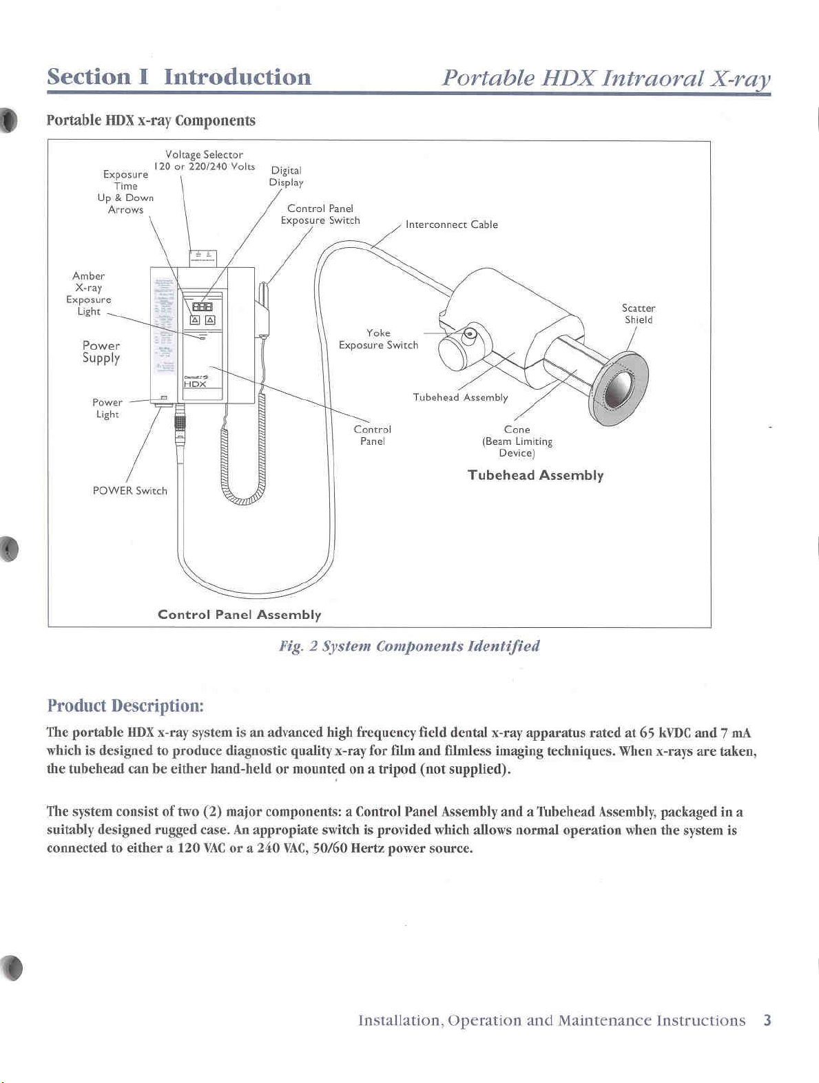
Product
The
which
the
tubehead
The
suitably
connected
Description:
portable
is
system
HDX
designed
can
consist
designed rugged
to
either a 120 VAC
to
be
Control
x-ray
system
produce
either
of
two
(2)
case.
Panel
Assembly
is
an
advanced
diagnostic
hand-held
major
components: a Control
An
appropiate
or a 240
Fig. 2 System
high
quality
or
mounted
VAC,
x-ray
switch
50/60
on a tripod
Hertz
Components
frequency
for
is
provided
film
Panel
power
field
and
(not
Identified
dental
filmless
supplied).
Assembly
which
allows
source.
x-ray
apparatus
imaging
and a ‘Tubehead
techniques.
normal
operation
rated
at
65
When
Assembly,
when
kVDC
and 7 mA
x-rays
are
packaged
the
system
taken,
in
a
is
Installation,
Operation
and
Maintenance
Instructions
3

Section
DentalEZ®
with
applicable
assembled,
accordance
The
installer
1;
Installing
with
the
N
Checking
performing
required.
Maintaining
equipment.
below
II
Certification
certifies
checked,
with
is
responsible
manufacturer's
the
for this
that
Regulations
calibrated,
the
instructions
the
Portable
calibration
the
calibration
records
Use
purpose.
this
for:
X-ray
of
the
Maintenance
&
equipment
and
Standards
and
maintained
in
this
manual.
in
accordance
instructions.
of
the
machine
procedures
the
location
Records
complies
when
in
and
when
of
the
Record
Tubehead
Cone Model
Serial
Control
*
Panel
Manufactured
Model
No.
No.
Model
Serial
No.
Serial
No.
No.
by:
DentalEZ®,
DentalEZ
No.
Lancaster,
PA,
>
USA
*
Providing
Maintenance
responsible
future
This
product
the
Radiation
applicable
Routine
the
Manual
for
reference.
complies
Control
at
date
of
Install
Maintenance
Installation,
to
the
maintaining
with
DHHS
for
Health
manufacture.
and
Maintenance
Operation
user
the
manual
standards
Safety
Act
By
By
and
who
for
under
of
1968
is
Maintenance
Date
Date
Record
Checks & Calibration
Checks & Calibration
By
By
Date
Date
4
DentalEZ
Portable
HDX
Chart 1 Maintenance
Intraoral
Record
X-ray

Section
III
Statements
and
Symbols
Used
Portable
HDX
Product
Note:
Read
Safety/Warning
and
all
special
carefully
Statements
on
the
safety
Alternating
Attention,
Dangerous
=?
Fuse
IN-position
and
Portable
instructions
note
HDX
the
meanings
current
consult
voltage
of
the
Symbols
X-ray
and
accompanying
Main
System.
warnings
of
each.
Switch
used
in
this
documents
Intraoral
in
this
manual
manual,
X-ray
and
OUT-position
lonizing
OFF
(power)
ON
(power)
Protective
Type
B
X-ray
X-ray
@0>©-O0*Dhf
-|
source
source
of
the
radiation
earth
(ground)
assembly
assembly:
Main
emitting
Switch
Installation,
Operation
and
Maintenance
Instructions
5

Section
IV
Installation
Unpacking
Components
System Contents
Carrier
Tubehead
Assembly
Control
20
cm
Instruction
International
NorthAmerican
Shield,
Interconnect
Fuses 5 amp
Installation
the
Case
Assembly
Instructions
Panel
Round
Manual
Scatter,
amp
“
amp
3
vs
amp
of
Components
of
the
Portable
Cone
Power
Cable
Slo
Slo
Power
Cone
Blo - 3
Blo
Slo
Blo
Slo
Blo - 2
the
Tubehead
Cord
Cord
-
3
-
Pes.
Pes.
2
Pes
Pes.
HDX
}
and
x-ray
120
240
}
Cone
Volts
Val
olts
Tools
Required
Fluke”
Digital'M
Phillips
Slotted
Allen
Needle
Adjustable
73
Digital
Pulse
Head
Screwdrivers
wrench
nose
“*
Fluke®
is a registered
*
EDS?
is a registered
DE.
Multimeter*
Counter,
Screwdriver
5/64”,
pliers,
wrench,
trademark
EDS
(small
6”
6”
trademark
of
of
or
equivalent
Model
(small
and
the
Engineered
and
medium)
Fluke,
Corp.,
Design
XR201*
medium)
Everett,
System,
or
equivatene
WA.
Wilmington,
Note:
The
Verify
Thread
For
O-ring
cone
hand
CAUTION:
Tubebead
is
evident.
return
assembly
for
repair
replacement.
cone
has
is
on
into
held
use,
A
Do
not
if
an
Always
Tubebead
to
the
or
no
filters
threaded
Tubehead,
slide
scatter
install
oil
leak
factory
attached.
base
of
cone.
and
align
shield
grooves.
flush
to
Cone.
四
CE
Align
Grooves
Scatter
Shield
6
DentalEZ
Portable
HDX
Intraoral
Fig. 3 Installation
X-ray
of
Cone
and
Shield
to
Tubehead

Section
IV
Installation
Portable
HDX
Intraoral
X-ray
Assembly
1.
Measure
between
A.
100
B.
200
Remove
120
VAC
FOR
120
A.
Insert
B.
Insert
FOR
240
A.
Insert
B.
Insert
Instructions
and
determine
either:
to
130
VAC,
single
to
260
VAC,
single
top
cover
or
240
VOLT
two 5 Amp
1/4
Amp
VOLT
two 3 Amp
1/8
Amp
of
Voltage
VAC
setting,
OPERATION:
fuses
fuse
OPERATION:
fuses
fuse
the
phase
phase
into
into
power
and
and 5 Amperes,
Selector
then
into
Main
I/O
Fuse
Selector
into
Main
I/O
Fuse
Selector
supply
10
Amperes,
Switch
replace
Fuse
holders
holder
Fig. 5 |
Voltage
Fuse
holders
holder
Fig. 6 |
Voltage
line
voltage
50/60
50/60
receptacle,
top
cover.
located
in
bottom
Wwe
—
|
located
in
bottom
200
t0
|
|
130
VAC
1
260
VAC
and
Hz.
Hz.
turn
Front
in
of
power
in
of
power
——
|
amperage.
or
Voltage
Fig.4
Power
Supply
view
bottom
supply.,
bottom
supply.
|
The
supply
Selector
[Ke
ia
must
Switch
be
knob
rated
to
100
to
vac
either
130
sare
left
side
of
power
supply.
|
FI,F2
Fuse
5
left
side
ト
|
ai
|
AMPS
of
power
>
supply.
(8)
Pal.
<
(A)
FI,F2
3
AMPS
Fuse
|
Select either
power
Insert
6.
power
For
of
supply.
connector
supply.
either
Tubehead
hand-held
А.
B.
120
by
FOR
and
For
(See
volt
or
on
end
or
tripod
turning
TRIPOD
turn
14-20
Assembly
Tubehead
HAND-HELD
figure
240
volt
of
Tubehead
mounted
cone
clockwise
operation
screw
Fig.7
of
to
tripod
operation
3.)
power
supply
Interconnecting
use
until
of
Tubehead - Turn
on
tripod
Gr
/
/
of
Tubehead - Slide
Installation,
cord.
of
Tubehead,
seated.
into
threaded
Insert
proper
Cable
install
Tubehead
hole
into
Shield
Operation
round
cone
on
in
side
and
end
into
receptacle
to
threaded
its
side
of
yoke.
Scatter
over
Maintenance
receptacle
in
bottom
opening
over
top
front
end
Instructions
in
bottom
of
on
front
of a tripod
of
cone
of
7

Section V System
Checks
and
Calibration
DentalEZ
25
System
The
require
upon
listed
these
compliance
Preliminary
Item
Labels
Other
Warning
Tubehead
Cone
Control
Exposure
or
Exposure
Checks — General
Portable
adjustment
installation
below
checks
Labels
Statement
(BLD)
Panel
Switch
Tubehead
Switch
X-ray
and
again
and
with
regulations
Checks
Information
is
factory
during
perform
during
calibrations
Check
Verify
Verify
Verify
that
*
legibility
legibility
Check
Inspect
necessary.
Inspect
calibrated
installation.
the
annual
cannot
labels
Tubehead
for
oil
for
cord
and
preliminary
maintenance.
are
not
be
for
Assembly
of
of
leaks.
damage.
for
damage.
should
However,
checks
performed,
assured.
the
following
all
other
warning
If
statement
found, return
Lead
lining
Switch operation
not
If
+
labels.
must
A
Note:
Refer
(Section
components.
Dentalez®
assistance.
components
Control
Tubehead
on
cover
Panel
the
should
RADIATION
fails
preliminary
calibrated.
repair
XI,
power
to
entire
is
to
Maintenance
pages
If a problem
Customer
are
legible
*
supply
factory
interior
be
smooth
Cone
for
HAZARD:
checks,
DO
NOT
complete.
Service
24-42)
for
Service
and
in
place:
cover.
replacement.
surface
and
positive.
Do
not use
or
if
operate X-ray
Information
replacement
persists
of
for
technical
cone.
Replace
contact
Replace
X-ray
it
cannot
of
if
if
be
until
cone
damaged.
it
if
Line
Voltage
Calibration
To
complete
*
*
*
*
*
8
Checks
Preliminary
Power-ON
Line
voltage
Calibration
Calibration
DentalEZ
AM
a
installation,
RADIATION
switch
Measure
either
OPERATE
and
System
checks
sequence
regulation
checks
procedure,
Portable
is
activated.
incoming
100
follow
checks
check
for
kV
if
HDX
HAZARD:
line
to
130
VAC
THIS
SYSTEM.
Checks
these
steps:
and
mA
required
Intraoral
X-rays
Unauthorized
are
voltage
or
200
Contact
X-ray
emitied
use
at
the
Incoming
to
260
an
electrician
when
is
probibited.
VAC.
If
control
Power
outside
or
local
panel
is
energized,
Receptacle.
of
these
power
Voltage
limits,
utility
company
DO
and
range
NOT
either
under
ATTEMPT
to
correct.
exposure
load
TO
is

Section V System
Checks
and
Calibration
Portable
HDX
©
6
Power-ON
turn
system
sa
Calibration
Note:
require
The
mA
voltages
checked
removing
supply
Remove
Connect
multimeter
to
terminals
inside
yoke
following
the
chart
Sequence
ON.
RADIATION
checking
block
cone
The
X-ray
only a calibration check
and
can
without
cover.
yoke
of
CAUTION:
calibration,
waiting
microprocessor
operator
and
the
end
in a safe
Check
kV
be
the
power
end
2.
Before
from exceeding
Refer
HAZARD:
calibrating
of
the
direction
for
kV
and
is
factory
sense
cap.
Potentiometer
(Do
Fig. 9 kV & mA
taking
take
several
15
seconds
is
Power | Exposure | Exposure | Meter
Check | Meter | cwitch|
Multimeter
to
ha
() to
mA
Time | Go.
If
kV,
mA,
above
end
chart
cap
White
Multimeter
Yoke:
to
(lead
to
(+)
lead
Brown
to | ON
à
White
Digital
=
Place
in
front
of
cone
Chart 2 Calibration
and
time
are
within
the
system
is
to
Page
11,
Operation,
While
cone
mA
calibrated
Fig. 8 Yoke
not
any
between
programmed
performing
procedure,
with lead
away
from
during
adjust)
long
0.10
the
system
Yellow
Test
exposures
second
either
or
aim
any
person.
and
SHOULD
installation.
End
Cap
Brown
White
Points
to
check
exposures
exposures.
to
prevent
duty
cycle.
Setting | Switch | Reads
464
166
YDE
rose | 1680
206
|
seconds | Read
Settings
limits
calibrated.
È
Meter
as
Reinstall
listed
+72
voc
20
vom
in
yoke
Installation,
to
If
the
the
any
range,
Measure
1.
Measure
2.
Set
3.
Make
Ll
120/230
Fig.
10
4,
Calculate
Examples:
No
load
voltage
The
an
to
+
the
under
Regulation % =100x(118115)/115 = 100
Result
If
not
under
(100
КУА
regulation
Setup
A
Operation
of
the
kV,
continue
Line
Regulation
incoming
timer
to 2 second
exposure
、
White
VAC
Inpui
line
Regulation
where
voltage
load
of
either
within
for
4%,
load
to
130
buck-boost
after
Calibration
SHOCK
supply
TURN
MULTIMETER
Use
an
CAUTION:
discharge
and
green
connecting
Intraoral
mA,
or
time
Calibration.
line
voltage.
exposure
while
reading
U
o
Line
Voltage
regulation
%
=
100 x Va
V, = voltage
V, = voltage
120
Volts
=
118
volts
=115
volts
=100x3V/115
=
100 x .026
=
2.6%
example
call
voltage
VAC
HAZARD:
are
POWER
insulated
Wait 4 minutes
after
and
is
within
the
local
is
not
or
200
transformer.
installing
All
at
dangerous
OFF
LEADS
adjustment
power
wires
must
control
Maintenance
panel.
readings
are
(See
time.
multimeter.
Black
©
Green/Yellow
Measurment
as
follows:
VD,
with
no
load
under
load.
230-240
36
30)
100 x 6V/230
=
100 x .026
=
2.6%
4%
tolerance.
utility
company.
within
to
transformer.
circuits
WHEN
OR
be
operating
260
VAC),
Remeasure
inside
voltage
CONNECTING
MOVING
for
is
OFF.
below 2 VDC
Instructions
X-ray
out
of
figure
u
x(236-230)/230
tool.
capacitors
Voltage
10.)
Points
Volts
If
the
range
install a 1.5
line
power
levels.
JUMPER.
to
at
red
before
9

Section
Remove
Remove
Reconnect
control
power
KV (Red)
GND
(Blk)
Detail
AT
NOR
7-Pin
i)
Hi
V
System
panel
supply
and
mA
AD|
R201
from
mounting
cover.
4-Pin
connectors
Switcher
o
Checks
bracket
on
Board
and
on
front
control
Calibration
of
power
panel.
supply
cover.
Unplug
the
DentalEZ
7-pin
and
4-pin
connectors.
25
Хх
©
jmper
1205
一
Detail
“B"
lea
e
4
)
A
R202
FIL
AD}
R203
Calibration
Chårt
"alibrati:
Calibration
Settings
aa
@
Note: A nonconductive
inside
use a metal
Turn
Place
Detail
Connect
cover
the
Set
Turn
IMPORTANT:
counterclockwise
potentiometer
Set
Press
meter.
Chart
è
RADIATION
cone
the
power
jumper
B).
as
(+)
lead
the
meter
the
the
exposure
and
3
with lead
power
screwdriver
OFF.
J205
the
meter
follows:
to
the
to
power
Turn
1/8th
hold
the
FIL
mA
Fine
mA
KVP
HAZARD:
supply
in
to
(-)
lead
brown
read
switch
R201, R202,
until
time
exposure
[O
Fig.
11
CALIBRATION
7.4
VDC
to
7.6
68
VDC
t07.2VDC
6.6
to
VDC
6.4
While
performing
or
aim
the
cone
screwdriver
for
adjustments.
for
the
following
the
CAL
(See
figure
the
contacts
to
the
white
terminal.
+8.00
of a turn
ON.
stopped.
to
2.00
VDC.
and
(45°)
seconds.
switch
Yellow
System
VDC | CAL | R203
VDC
behind
Then
clockwise.
Calibration
J205 | Adjust | Yellow
|
in a safe
is
terminal
R203
turn
and
|
the
checking
direction
included
DO
NOT
steps.
11
above,
the
yoke
and
(FIL)
each
read
the
RIO
R202
Pots
and
NIA
(+)|
Black
|
and
away
Adjust
+7.60
‘Turn
Place
Detail
Turn
Using
meter
exposures.
Move
terminal.
Using
meter
exposures.
Calibration
covers
calibrating
from
R203
VDC
the
power
jumper
A)
the
power
2.00
reads
the
2.00
reads
carefully.
White
Test
Points
|White|
GRND
Brown | Power | Timer | Exposure
1 | Pos
o
|
Neg
procedure,
any
person.
(FIL)
during
switch
J205
position.
switch
second
between
(+)
meter
second
between
is
complete;
(+)
ON | 200
N/A
either
until
multimeter
exposures.
OFF.
in
NOR
ON.
exposures,
+6.80
lead
exposures,
+6.40
turn
Brown
Press,
Read,
Adjust
block
the
end
of
(See
adjust
and
from
adjust
and
X-ray
reads
figure
R201
+7.20
brown
R202
+6.60
OFF.
+7.40
11
above,
(mA)
VDC
during
to
yellow
(kV)
VDC
during
Assemble
the
to
until
until
all
10
DentalEZ
Portable
HDX
Intraoral
X-ray

Section
Turning
4 à
©%
RADIATION
factors
portable
and
CAUTION:
occur,
the
System
operator,
Fig.
VI_
refer
Fig.
Fig.
14
Note:
The
computer
correct,
for
control
disconnects.
panel.
one
displays
second.
panel
Turn
Fig.
New
installations
Note:
thousand,
sounds 4 times.
maintenance
When
the
for
Operation
ON & Self
HAZARD: Observe
and
operating
X-ray
12
Turning
If
the
to
may
following
User
LISI
LI
13
Software
111
Revision
TIE
LTI
Software
CHS
displays
15
Number
Display
display
the
display
To
service.
Checksum
calculates
(a
standard
If
checksum
power
rir
lt]
LILI
of
(in
000.
exposure
flashes 4 times
continue
Diagnostics
instructions
be
dangerous
System
sequence
Service
Information.
Level
5
Display
the
checksum,
software
is
not
error
OFF,
code
and
LI
Unit
Exposures
thousands)
count
exposure
safe
exposure
as
to
patient
ON
does
Display
and
signal)
correct,
Ell,
replace
reaches
and a chime
count,
and
control
call
Installation,
the
not
if
the
149
for
Portable
Note:
The
when
in
The
separate
A,
The
B.
Note:
time
the
again
the
seconds
.38
1.88
X-ray
Standby
X-ray
Adjusting
If
is
selected
system
be
an
Fig.
Preferred
system
is
is
is
actions, A through
Condition
may
exposure
displayed.
16
Current
to
two
an
exposure
an
exposure
now
be
the
Exposure
and
is
turned
HDX
Time
is
initially
decimal
in
left
2
To
increase
Exposure
To
press
“e
0
内
change
DI
Minimum
Time
Fig.
change
and release
Exposure
Change
Operation
Fig.
17
Exposure
the
exposure
or
the
DOWN
JE
ゴロ ゴビ
34 JI
93 ゴリ
Fig.
18
Exposure
Q0U
Maximum
Exposure
19
Exposure
the
preferred
both
Fig.
20
Time
Buttons
and
Intraoral
JI
„II
Preferred
standby, ready
in
time
the
ON,
2)
X-ray
3)
Time
Time
Time
#5
the
preset
turned
places.
time
of
time
of
E.
standby
Time
other
system
is
the
preferred
than
OFF
ON
Power
Time
Display
time,
press
button
Min
time
the
to
ゴゴ
Time
Sequence
After
Exposure
and
Max
setting,
UP and
VIIA
Maintenance
X-ray
Display
exposure
ON.
It
displays
For
example:
0.38
seconds;
1.88
seconds.
for
one
of five
indefinitely.
the
preferred
turned
OFF,
time
ゴゴ
Preferred
4)
the
decrease.
reaching
Time
returns
Settings
simultaneously
DOWN
displays
Time
UP
button
4
Steps
Every
Second
Dl
Maximum,
to
Minimum
arrows.
Instructions
time
when
will
the
to
II

Section
The
control
Adjust
point
Select
or
Mode,
and
the
DOWN
VI
panel
as
the
new
arrow.
ゴゴ
When
Time,
permanent
Wait 5 seconds.
Turn
displayed.
C.
Making
Fig.
the
turn
the
system
CAUTION:
cycle.
be
21
display
the
memory.
an
Exposure
made
Operation
is
now
indicated
chime
One
sounding 2 times
Preferred
Preferred
shows
system
ON.
The
Always
0.25
every
in
the
by
the
Time
Exposure
the
new
OFF
to
store
new
preferred
observe
second
15
seconds.
Preferred
blinking
per
by
pressing
Plon
Time
Setting
desired
the
the
system
X-ray
exposure
Time
decimal
second.
the
Preferred
new
time
time
is
UP
in
now
duty
can
Error
Note:
sounds.
error
Information
Replace
If
to
D.
codes:
Fig.
Release
If
code
the
an error
User
Service
Turning
23
exposure
for
code
DentalEZ
EU
Exposure
switch
E02
Fig.
exposure
Information.
the
Switch
released
within
switch
appears.
otber error
15
is
Refer
codes.
EDUC
24
Switch
held
too
displays
System
switch
OFF
in
during
seconds
depressed
its
|
tou
soon. . .
to
long.
holder.
an
exposure,
after
too
User
>
©
chime
long,
Service
refer
Press
and hold
Release
à
gg
Fig.
22
Select
exposure
switch.
Note:
After
power
wbicb
operational.
indicated
end
OFF,
is
of
and
applied
takes
by
the
the
Exposure
switch
pressing
to
the
0.6
seconds
Then
the
the
amber
exposure,
chime
=
Time
until
tbe
exposure
X-ray
exposure
X-ray
the
X-ray
sounds.
chime
tube
to
sounds.
filament,
become
begins,
light.
light
switch,
fully
as
At
the
turns
Automatic
inadvertently
exposures
cool
microprocessor
programmed
tube.
to
60
Any
minute
0.50
System
1.
2.
duty
without
down
combinations
second
between
After
each
times
Cones
disinfectant
cleaned
All
mild
the
can
be
exposures).
cleaning
(BLDs):
other
soapy
Fig.
25
Turning
cycle
control:
tries
to
initiate
waiting
the
exposures,
in
the
control
to
automatically
exposure,
last
emission
of 1 second
made
(e.g.
information:
Use
only
(liquid
while
assembled
parts:
water.
Use
System
If
for
an
four
non-alcohol
cloth
OFF.
an
operator
two
consecutive
the
panel
protect
OFF
duration
of
exposure
0.25
or
spray).
to
Tubehead.
dampened
X-ray
tube
the
is
the
interval
is
provided.
second
based
Can
to
X-ray
equal
per
or
two
be
with
12
DentalEZ
Portable
HDX
Intraoral
X-ray
Section
VII
Exposure
Time
Settings
Portable
HDX
Speed
(Kodak
Exposure
Maxillary
Mandibular
Speed
(Agfa
Exposure
Maxillary
Mandibular
|
Speed
(Kodak
|
Exposure
Maxillary
Mandibular
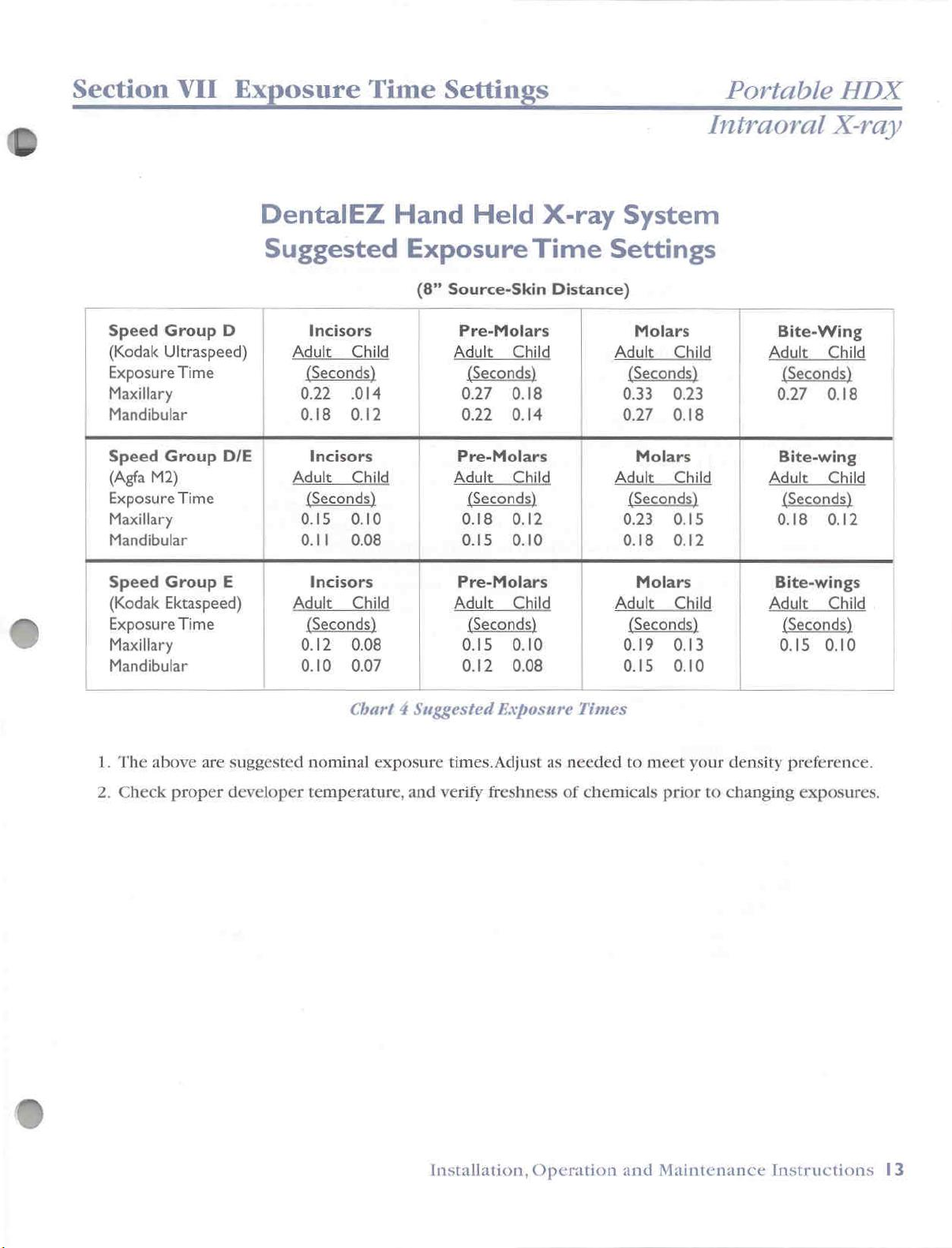
DentalEZ
Suggested
Group
Ultraspeed)
Group
M2) Adult
Group
Ektaspeed)
Time
Time
Time
D
D/E
E
Incisors
Adult
Seconds
0.22 .014 0.27
0.18 0.12 0.22
Incisors
|
Seconds)
0.15
0.11
Incisors
Adult
(Seconds) (Seconds)
0.12
0.10 0.07 0.12 0.08 0.15 0.10
Hand
Held
Exposure
(8”
Source-Skin
Pre-Molars
Child
Child
0.10
0.08
Child
0.08
Chart 4 Suggested
Adult
|
Pre-Molars
|
Adult
|
|
0.15 0.10
Pre-Molars
Adult
(Seconds
(Seconds)
0.18 0.12
0.15
X-ray
Time
Distance)
Child
0.18
0.14
Child
Child
0.10
Exposure
Intraoral
System
Settings
Molars
Adult
(Seconds)
0.33 0.23
0.27 0.18
Molars
Adult
0.23 0.15
|
0.18
Molars
Adult
(Seconds)
0.19 0.13 0.15
|
Times
Child
Child
Seconds)
0.12
Child
Bite-Wing
Adult
|
(Seconds)
0.27 0.18
Bite-wing
Adult
(Seconds
0.18
Bite-wings
Adult
(Seconds)
X-ray
Child
Child
0.12
Child
0.10
1.
2.
The
above
Check
are
proper
suggested
developer
nominal
temperature,
exposure
times.Adjust
and
verify
Installation,
as
freshness
Operation
needed
of
chemicals
to
and
meet
your
density
prior
to
changing
Maintenance
preference.
exposures.
Instructions
13

Section
ectio
VIII
Darkr
arkroom
Practices
i
and
Procedures
DentalEZ
©
Darkroom
I.
General:
The
standardization
sharp
the
routine
film.
Also, a properly
Il.
Darkroom
(manual
A
good
should
1
or
equal)
dry
areas
recommendations).
especially
more
e
To
check
darkroom
darkness.
unsafe
Practices
and
contrasty
will
usually
Recommendations:
and
automatic
darkroom
include a 15
designed
(if a film
important
sensitive than
for
door
Check
light
should
unsafe
and
sources
and
Procedures
of
the
x-ray
films
reduce
processed
processors)
be
watt
(maximum)
to
be
other
than
Further,
if
the
“D”
film
light
leak(s)
wait
darkroom
are
film
exposing / film
which
the
film
film
large
enough
used with
Kodak
to
prevent
user
is
using
(ULTRA-SPEED)
in
the
in
the
darkroom
for
light
found,
eliminate
are
rich
contrast
minimizes
so
that
frosted
the
film
is
used,
we
fogging
Speed
darkroom:
leaks
them
handling / film
with
diagnostic
thus
making
the
patient
there
are
light
bulb
and
used,
and
be
suggest
of
the
Group
to
unsafe
for
about 5 minutes
around
films,
“E”
light
With
the
using
contacting
the
weather
processing
information.
it
more
radiation
“dry”
and
known
positioned
the
darkroom
(e.g.
Kodak
condition(s).
safelight
door,
vents,
technigues
Any
difficult
exposure.
“wet”
filter
the
EKTASPEED)
at
areas.
(for
least
film
must
turned
for
your
eyes
cracks,
stripping,
will
result
deviation(s)
to
see
detail(s)
The
safelight
example, a Kodak
four
(4)
feet
from
manufacturer
be
light
film
OFF,
close
to
adjust
ceilings
tape
ete...
for
tight
which
the
to
tiles
in
from
in
the
GBX-
the
their
-
is
the
etc...
If
A.
If
®
Manual
A
following
Darkroom
Hand
darkroom
A.
Hand-Tank
B.
Thermostatic
C.
Safelight
light
D.
Floating
E.
Accurate
*,
Solution
G.
Scrub
H. A chart
Equipped
Tanks:
which
items
(as
[it
filter - for
Thermometer.
darkroom
stirring
brushes
for
With:
has a manual
minimum):
with 1 gallon
water
should
temperature
include a 15
example, a Kodak
timer.
paddles
(one
for
the
listing
the
date
developing
solution
inserts.
control
watt
cat
(one
for
the
developer
when
the
tank
installed
valve.
(maximum)
no.
GBX-1
developer
and
one
solutions
in
it
frosted
Safelight
and
one
for
the
fixer
were
last
should
light
or
equal]
for
the
insert).
changed.
consist
bulb
and a known
fixer
of
the
insert).
14
DentalEZ
Portable
HDX
Intraoral
X-ray

Section
VIIL_
Darkroom
Practices
and
Procedures
Portable
HDX
Simplified
Ideally,
follow
Developing
we
this
Note:
Procedure:
recommend
simplified
For
consistent
that
developing
(using a second
*
75
Intraoral
‧
Three-8”
+
Any
combination
intraoral
Developer:
of
water.
Stir
with
Fixer:
One
Stir
you
follow
procedure.
results,
set
x
films)
One
we
of
solutions)
films
10”
films,
(1)
developer
(1)
ounce
with
fixer
the
recommend
(all
sizes),
or
...
of
the
above
ounce
of
paddle.
of
fixer
paddle.
solution
manufacturer's
replenishing
after
processing:
or
...
(one
8” x 10”
developer
concentrate
concentrate
(do
the
developer
film
not
dilute).
Intraoral
recommendations
and
approximately
diluted
with
two
fixer
solutions
equals
(2)
X-ray
-
or
25
ounces
®
Automatic
A
darkroom
following
B.
Safelight
-
for
C.
Paddles
D.
Scrub
Processing
which
items
[it
should
example, a Kodak
for
stirring
brushes
E. A Thermometer.
An
automatic
system
If
the
processor
is
positioning
film
maintained
of
it
System
has
an
(as
minimum):
include a 15
the
(one
for
processor
in
accordance
is
installed
relative
automatic
cat
no.
solutions
the
developer
will
in
the
to
the
“dry”
processing
watt
(maximum)
GBX-1
(one
Safelight
for
and
standardize
with
the
darkroom,
area,
and
system
frosted
or
the
developer
one
for
your
film
procedure
the
above
the
procedure
installed
light
equal]
and
the
fixer
processing
recommended
safelight
in
it
should
bulb
and a known
one
for
the
fixer
insert).
technique provided
by
the
recommendations,
to
check
for
light
consist
of
light
tank).
the
the
manufacturer.
leak(s)
filter
apply.
Installation,
Operation
and
Maintenance
Instructions
15

Section
ection
*
Important
1.
Your
replenishment
For
8
solution
solutions
For
A.
operating
B.
developer
desired
paddles)
VIII
Darkr
arkroom
Tips:
automatic
those intraoral
ounces
those
Each
Each
of
working
daily
or
be
changed
larger
time
it
temperature
time
the
and
number
before
film
processor
feature:
only
processors
strength
after
processing
every 3 to 4 weeks.
processor
is
turned
processor
fixer
tanks
of
films,
processing
Practices
may
developer
equipped
“ON”,
or
and
else
is
to
make
stir
the
allow
light
turned
films.
i
or
may
without
20
to
30
with
automatic
sufficient
films
“ON”,
sure
sufficient
each
solution
and
not
be
automatic
and
fixer
films.
may
time
be
check
in
Also,
solution
produced.
Procedures
equipped
solution
replenisher
it
for
the
solution
solutions
the
replenisher
with
replenishment:
should
is
recommended
replenishment:
the
solutions
levels
are
available
DentalEZ
the
automatic
be
to
be
in
the
to
tank
(use
solution
added
that
to
the
heated
replenisher
process
separate
22
each
up
the
to
III.
Common
Three
A)
2.
FILMS
For
those
It is
important
reduce
Film
of
the
+
A)
Films
*
B)
Films
+
©)
Films
ARE
Light films
I
Too
2.Slower
3.Short
4.
5.
6.
processors
that
the
possibility
Problems
most
common
are
too
are
too
lack
contrast
TOO
LIGHT
may
short X-ray
speed
developing
Developing
Developing
X-ray
machine
equipped
the
processor
of
light
x-ray
film
light
(not
dark
(too
(Cannot
(not
be
caused
exposure
film
being
time
solutions
solutions
too
defective.
with
daylight
be
fogging
install
the
loaders:
in
an
films.
problems encountered
enough
much
enough
by
one
time
used
(hand-tank).
density)
density)
easily
see
density):
or
more
selected.
diagnostic
of
the
cold.
exhausted.
area
of
subdued
are:
detail)
following:
lighting.
This
will
help
16
DentalEZ
Portable
HDX
Intraoral
X-ray

Section
VIII
Darkroom
Practices
and
Procedures
Portable
HDX
1.
Too
short X-ray
Check
been
set for
2.
Slower
If
Speed
SPEED
film.
3.
Developing
If
the
films
tions
may
the
solutions
processor - if
for
the
4.
Short
developing
Be
sure
manufacturer.
or
so,
only
darken
will
not
visible
and
some
HDX
Suggested
the
speed
film
“E”
film
Kodak)
solutions
are
be
too cold.
are
solutions
heater(s)
to
follow
If
those
and
be
darken
and
thus
darkness
exposure
speed
being
(e.g.
is
being
too
at
to
time
the
the
areas
visible - the
sufficiently
valuable
time
exposure
of
the
used:
Kodak
exposed.
too
cold:
light
when
If
manual
the
recommended
are
warm
(hand-tank
time/temperature
films
are
of
the
diagnostic
which
selected:
Time
film
being
EKTASPEED)
Check
the
tank - add
too
cold
up
solutions?
system):
removed
film
emulsion
areas
of
to
be
visible
makes
it
Setting
used,
is
routinely
film
packet
recommended
warm
temperature
after
turning
If
yes,
developing
from
the
which
the
emulsion
and
as a result,
information
more
difficult
Chart
and
repair
to
verify
for
the
used,
(and
box)
developing
water
ON
developing
which
will
to
(usually
the
the
film
recommendations
received a large
received a lesser
many
be
lost.
to
visualize
that
correct
tooth
processor,
being
perhaps
to
verify
time
the
water
68
degrees
processor
solution
of
the
Further,
diagnostic
is
amount
Intraoral
exposure
examined.
Speed
followed,
bath
did
prematurely
subtle
the
“D”
brand
F).
you allow
as
provided
name/speed
(not
If
automatic
needed.
of
radiation
amount
grays
films
will
details.
X-ray
time
has
(e.g.
ULTRA-
then
the
solu-
solutions)
film
enough
by
the
solutions
after 1 minute
will
of
radiation
will
not
lack
contrast
of
until
time
be
5.
Developing
Films
contrast
Replenishment
consistent
6.
X-ray
Perhaps
your
machine
processed
machine
time
solutions
in
(like
reusing
Procedure
developing
defective:
the
actual
counter
as
necessary.
exhausted:
solutions
coffee
results
X-ray
to
verify
which
grounds
above
month-to-month.
exposure
the
are
to
or
the
is
shorter
exposure
Installation,
exhausted
brew
manufacturer's
than
time.
will
another
what
If
incorrect,
Operation
pot
be
lighter
of
recommendations
the
timer indicator
troubleshoot
than
coffee),
and
Follow
Maintenance
normal
the
to
maintain
reads.
and
repair
and
will
lack
Simplified
Suggest
the
X-ray
Instructions
using
17

Section
B)
FILMS
1.
Too
VIII
ARE
TOO
-Too
=
„Faster
D
.
Short
D
.Developing
.
X-ray
JE
long
X-ray
Darkroom
DARK
long
X-ray
exposure
speed
cone
machine
exposure
film
installed
solutions
defective.
(too
being
time
much
on
Practices
density):
time
selected.
used.
X-ray
but
too
hot.
selected:
and
exposure
Procedures
time
set for
long
DentalEZ
cone.
25
Check
been
2.
If
EKTASPEED)
film.
3.
Manual
followed
until
4.
Perhaps
your
machine
HDX
set
for
Note:
Faster
Speed
speed
*D”
Developing,
Hand
then
the
solutions
X-ray
machine
the
time
as
Suggested
the
speed
The
actual
gested
process
setting
film
(e.g.
Kodak
is
běing
solutions
Tank:
the
defective:
actual
counter
necessary.
Exposure
of
the
exposure
on
the
film,
being
used:
ULTRASPEED)
exposed.
too
hot:
If
the
films
solutions
are
at
the
X-ray
exposure
to
verify
Time
film
being
time
setting
the
correct
if
the
density
Check
are
too
may
be
too
recommended
is
longer
the
exposure
Setting
used,
on
chart.
of
the
is
routinely
film
packet
dark
when
hot.
Add
temperature
than
time.
Chart
and
If
to
for
the
X-ray
it
is
film
used,
(and
the
ice
what
If
incorrect,
verify
the
not,
is
still
box)
recommended
cubes
the
that
tooth
perhaps
(usually
being
is
usually
reset
the
too
to
to
the
timer indicator
troubleshoot
correct
within
x-ray
dark,
Speed
verify
development
water
68
degrees
exposure
examined.
25%
timer
it
may
be
“E”
film
brand
name/speed
bath
(not
F).
reads.
and
repair
time
of
the
and
retake
fogged.
(e.g.
Kodak
time
solutions)
Suggest
the
has
sug-
and
of
is
using
X-ray
C)
FILMS
If
more
c.)
DentalEZ
the
a.)
b.)
LACK
film
lacks
of
the
An
unsafe
The
processing
An
unsafe
Portable
CONTRAST
contrast
following
light
condition.
film
storage
HDX
(cannot
and
is
too
conditions:
chemicals.
location.
Intraoral
X-ray
easily
see
dark,
diagnostic
it
may
be
fogged.
detail):
Fog
is
usually
caused
by
any 1 or

Section
VIII
Darkroom
Practices
and
Procedures
Portable
HDX
D
Procedure
To
determine
amalgam
Read
because
to
penetrate
then
the
the
these
film
filing
printing
Procedure
1.
Unsafe
To
determine
steps:
a.
Light
wait
in
darkroom
found,
to
determine
if a
film
or a gold
areas
either
is
fogged.
to
check
Light
leak(s)
Source:
if
in
the
darkroom
for
eliminate
is
on
this
should
of
them
for
the
films
the
darkroom:
light
them
whether
fogged,
crown
page
through
be
“window-panel
and
source
were
for
about 5 minutes
leaks
around
using
the
film
place a dry
directly
thus
of
fogged
With
weather
on
the
expose
fogged
by
the
the
door,
is
fogged.
processed
top
of
this
filing
or
clear”
the
film).
films:
an
unsafe
safelight
for
your
vents,
stripping,
film(s)
page.
crown.
(the
If
you
light
turned
eyes
cracks,
tape
etc.
which
You
X-rays
cannot
in
the
OFF,
close
to
adjust
etc.
If
Intraoral
has
should
do
be
not
have
read
darkroom,
the
to
unsafe
either a large
able
to
read
sufficient
easily
darkroom
the
light
the
printing,
follow
darkness.
these
door
sources
X-ray
it
easily
power
and
Check
are
b.
Master
Insert
completely
composed
c.
To
determine
packet
an
exposed
stored
d.
To
determine
coin
safelight.
patient
outline
(allowing
15
watts
surface
film.
In
daylight,
the
film
and
clear.
to,
if
the
and
process
film.
in
an
area
if
the
on
top
of
it,
After 5 minutes,
film.
If
there
of
the
coin,
white
and
should
(it
should
unwrap a film
hanger
Rinse
If
which
and
light
and
box
of
it
immediately
this
film
was
safelight
place
is
no
the
safelight
to
expose
be a frosted
be
least 4 feet
directly
dry.
film
is
is
not
too
is
unsafe:
it
on
process
image
and
place
into
the
This
is
your
defective:
as
hot.
the
of
is
the
lamp),
away).
In
in
the
developer
clear
Try a new
Turn
ON
dry
work
the
film
the
round
unsafe.
film),
or
as
Check
the
it
Fixer
master
total
darkness,
the
master
box
the
surface
in
the
coin,
bulb
the
safelight
on a single
solution
film
for
to
which
remove
and
fixer
film,
of
film
safelight.
same
the
to
see
wattage
Unwrap a film,
so
that
manner
safelight
if
the
too
may
film
hanger.
about 2 minutes
all
other
the
film
solutions
it
may
and
repeat
it
is
as
is
safelight
large
be
too
as
be
outdated
this
exposed
you
would
safe-
If
filter
(it
must
close
or
until
films
will
be
from
the
film
though
test.
place a small
to
you
is
to
the
it
was
or
was
the
process
see the
cracked
not
exceed
dry
work
it
a
is
Installation,
Operation
and
Maintenance
Instructions
19

Section
2.
Film
If
3.
Chemical
VIII
Darkroom
Storage
Care
in
storage
humidity
degrees E and
Each
stock
A
good
after
to
exposed
exposure.
you
patient
where
bracket
and,
package
is
rotated
precaution
use).This
films
suspect
and
immediately
the films
table)
Fog
(pre
and
of
X-ray
of
course,
30
to
should
and
the
is
will
protect
even
films
are
are
temporarily
after
exposure
Caused
Practices
post
exposure):
film
is
extremely
radiation.
50
percent
be
placed
older
to
always
more
being
by
film
the
so
inadvertently
process
is
Contaminated
Ideally,
relative
so
that
used
store
X-ray
films
from
because
it.
If
the
stored
unsafe.
and
important
unexposed
humidity
the
expiration
first.
films
being
they
exposed,
film
(whether
Procedures
because
film
in
an
date
in
leaded
exposed
are
more
have
does
not
it
is
in
area
sensitive
show
the
Developer/Fixer
film
is
affected
should
is
storage
to
the
be
stored
properly
clearly
any
assistant take a film
any
uniform
shielded
visible
containers
stray
radiation.
after
exposure
fog,
then
pocket
Chemicals:
by
heat,
at
50
to
70
from
X-rays.
so
that
the
(before and
This
than
on a live
the
usual
or
on
the
film
applies
before
place
Suggest
developer
Note:
For
additional
suggest
following
following
dumping
and
Be
sure
a
brush
detect a faint
Hint:
information
the
enclosed
1.
Successful
2.
Exposure
3.
Quality
the
solutions
fixer
tanks.
to
use a different
can
contaminate
smell
When
Fixer
splashing
amount
during
Eastman
pouring
Solutions
of
the
on
procedures
Kodak
Intraoral
and
Assurance
presently
of
rotten
the
solutions
First
and
into
the
developer
developing
processing
X-ray
exposure
recommended
publications:
Radiography
Processing
in
Dental
in
scrub
brush
the
Developer
eggs.
very
solution
cycle)
and
for
Dental
Radiography
your
system,
for
each
tank.
into
the
slowly
tank
and
image
by
to
(the
which
contaminating
receptor
your
film
(N418).
Radiography
scrub
tank.A
Also,
processor
prevent
fixer
solution
is
normally
(film)
processor
(N413).
(N-416)
and
rinse
small
if
contaminated,
internal
any
carried
the
amount
tanks,
fixer
solution
can
tolerate a small
over
solutions
processing
manufacturer
thoroughly
of
Fixer
you
Always
from
by
the
again.
techniques,
and/or
the
may
Pour
film
on
the
we
the
20
DentalEZ
Portable
HDX
Intraoral
X-ray

Section
IX
Annual
Maintenance
Program
Portable
HDX
で
The
calibration
that
were
authorized
1.
Perform
2.
Calibration
A.
Remove
of
the
applicable
and
qualified
the
Preliminary
check
yoke
system
at
for
end
must
the
time
of
maintenance
System
kV
and
mA:
cap and
be
checked
manufacture.
personnel
Checks
connect
on
(place)
on
an
annual
Failure
relieves
page 8 of this
to
DentalEZ
meters
basis
have
manual.
as
per
to
assure
the
following
and
chart
Remove
Yoke
End
Cap
Fig.
26
Power | Exposure | Exposure | Meter
Check | Meter | switch | Setting | Switch | Reads
ky
mA | to
Multimeter
Yoke:
toYellow
() to
Multimeter
Yoke:
()leadto | ON
(+)
lead
White
(+)
lead
Brown
я
White
Digital
to
to
Impulse
Time | Gioni:
Counter
Place
in
front
of
cone
Chart
Poténtiometer
(Do
not
adjust.)
kV
and
mA
Test
iü)
seconds | Read
5Calibration
Settings
White
Yellow
Points
»
y
Meter
continued
annual
its
agent(s)
5:
áno
+66
voe
+68
to
+72
voc
200
+/-0.02
ia
Intraoral
compliance
maintenance
of
all
regulatory
X-ray
with
regulations
performed
responsibilities.
by
Note:
/f
complete.
B.
3.
Calibrate
4.
The
RW
mA
If
kV,
annual
and
exposure
mA
or
exposure
the
system
maintenance
time
time
by
following
program
readings
are
out
the
calibration
is
now
are
within
of
specified
complete
Installation,
specified ranges,
range,
procedure
and
the
normal
Operation
Reinstall
system
detailed
operation
yoke end
must
be
on
page
can
and
Maintenance
cap.
Calibration
calibrated.
10.
now
be
resumed.
check
Instructions
is
21

Section
X
User
Service
Information
Notes:
Table 1 User
1.
2.
SYMPTOM
Power
digital
Power
lit
during
Power
but
System
Digital
display
power
Film
Film
Film
ON
display
ON,
but
no
ON
digital
display
ON
density
density
Lacks
All
all
Error codes
by
x-ray
attempted
display
operates
all
8's
repairs
of
maintenance
Error
light
and
light
seguence.
too
too
Contrast
should
the
radiation
Codes
and
are
not
digital
produced
exposure.
is
not
is.
normally.
does
not
during
light.
dark.
E11
be
and
personnel.
lit.
display
lit,
performed
safety
regulations
above
PROBLEM
Primary
System
line
120
Light
connector
Problem
display
Film
or
Film
or
An
processing
film
by
which
but
volts.
is
is
under
is
over
unsafe
storage
maintenance
applicable
are
displayed
power
connected
voltage
inoperable
with
or
either
either
developed.
OFE
selector
is
disconnected.
either
display
under
developed.
over
light
condition,
and/or
problem.
service
at
are
to
240
set
or
digital
circuit.
exposed
exposed
an
unsafe
the
time
fault
volts
for
personnel
of
manufacturing.
conditions
CORRECTIVE
Check
OK,
service.
Replace
fuse
for
OK
maintenance
Call
service,
Portable
time
Check
correct
used.
Pages
procedure.
Check
correct
used.
Pages
procedure.
Refer
Procedures,
Pages
to
ensure
which
call
and
240
to
maintenance
cannot
must
building
maintenance
T3
fuse
set
voltage
volts.
operate
personnel
Do
not
X-ray
be
to
make
exposure
Also
refer
14-20.
Also
14-20.
to
14-20.
Check
to
make
exposure
refer
Check
Darkroom
Section
that
the
be
ACTION
circuit
with
selector
system,
personnel
attempt
because
set
properly.
sure
chart
to
Section
the
sure
chart
to
Section
the
Practices
VII
system
corrected
breaker.
personnel
correct
but
that
developing
that
,
meets
rated
switch
have
correct
for
to
use
Exposure
the
is
being
VIII
the
is
being
VIII,
developing
and
only
If
for
it.
the
,
The
following
sound
E01
22.
for
DentaleZ
Error
the
number
Portable
codes
of
times
HDX
will
be
displayed
indicated.
Exposure
prematurely
the
end
on
switch
of
the
the
digital
was
released
exposure.
Intraoral
X-ray
display
before
when
they
Error
code
5
seconds.
film
packet
occur,
will
Retake
or
and
the
clear
film
digital
chime
after
using
sensor.
will
new

Section
X
User
Service
Information
Portable
HDX
(continuation
E02
dg
d J
E03 e è
E04 d ce
Bİ8
ge:
55
-
of
Table
1)
Hand
Held
coiled
Switch
15
or
The
specified
Duty
Low
power
cord
pressed
seconds
coil
cord
line
cycle
incoming
switch turned
Exposure
or
Yoke
for
after
shorted.
voltage
minimum.
exceeded.
line
more
chime
is
below
voltage
switch
Exposure
than
sounds
the
when
ON.
or
Turn
power
seconds,
If
problem
held
switch
assembly
Turn
power
minutes.
persists,
personnel
voltage.
System
connected
Wait
OFE
Wait a few
If
problem
maintenance
service.
Try
set
until
then
Intraoral
OFF,
wait a few
and
turn
persists,
and
coiled
or
yoke
OFF
wait a few
again.
call
maintenance
to
check
for
240
to
120
error
message
continue
minutes
persists,
personnel
back
ON.
replace
cord
exposure
If
problem
incoming
volts,
but
volts
line.
is
usage.
and
try
call
for
X-ray
hand
switch.
line
turned
again.
EP
ge
149
(During
On
NOTE:
service.
Power
Sequence)
For
all
other
Error
codes,
System
but
voltage
240
volt
Faulty
Exposure
149,000
be
note
full
error
EEPROM
at
connected
selector
position
count
(the
150,000).
EEPROM
code,
has
turn
to
120
switch
reached
will
system
volts
in
OFE and
line|
Set
line
selector
volt
position.
Call
maintenance
service.
If
continued
is
desired,
personnel
Failure
EEPROM
operation
exposure
at
call
to
150,000.
maintenance
counting
Call
maintenance
for
service.
replace
will
not
of
the
count
switch
personnel
X-ray - the
will
to
of
exposures
the
affect
the
simply
personnel
120
for
stop
for
Installation,
Operation
and
Maintenance
Instructions
23

Section
To
maintain
Intraoral
subassemblies.
A
WARNING:
conditions
by
or
OFF
to
action.
Note:
If
not
provide a solution
DentalEZ”
assistance,
XI
system
X-ray
system
SHOCK
present
should
maintenance
above
immediately,
the
troubleshooting
the
corrective
Customer
Maintenance
compatibility,
replacement
HAZARD:
inside
never
Error
that
is
displayed,
Dangerous
the
power
remove
codes
must
personnel.
For
actions
to
the
Service
use
components/
supply.
the
power
E11
and
be
corrected
turn
other
tables
listed
problem,
for
technical
only
voltages
above
If
error
the
power
error
for
in
this
Service
HDX
The
operator
supply
contact
cover.
are
fault
or
repaired
code
switch
codes
refer
corrective
table
are
E11
do
Information
**
See
Error
Troubleshooting
codes
End
Power-ON
Errors
Exposure
Other
are
EL
Fig.
of
exposure
check
EO!
and
£02
count
has
error
conditions/Preferred
Table
2,
for
prefixed
|
27
by
|
Error
reached
149
thousand
Time
details.
the
letter
Γιο)
|
Code
Message
#*
Adjust
五:
Mode
EOI-E04
All
other
E
EUS
---
during
during
EUS
Note:
24
error
error
Problem
O
[]
DentalEZ
JI
上
standby
exposure
Error
disconnected
codes = User
codes = To be
| | ddd
I
code
Portable
M
DS
or
ode
E03
to
Service
performed
Table
2.
|
Exposure
before end
Exposure
more
chime
Exposure
while
time.
oa
Line
minimum
Duty
Maintenance
than
sounds.
changing
exposure
voltage
cycle
is
normal
X-ray
HDX
and
due
to
Intraoral
Information
by
Personnel
Cause(s)
switch
switch
switch
range.
not a default
slow
X-ray
released
of
exposure.
pressed
15
seconds
depressed | If
exposure
switch
below
exceeded.
discharge
maintenance
Troubleshooting
Error
exposure
Sensor.
for | Unit
after
or 2020
specified
clears
error
error
exposure
Replace
Power
Retry.
Check
Measure
install
Wait
preselected
condition,
of
capacitors.
service
Correction
code
using
will
reset
when
code
does
code
switch
Yoke
on
OFF;
If
problem
incoming
line
buck/boost
until
the
and
may
personnel
Table
clears
after 5 second.
new
film
in
five
seconds.
exposure
E17
Exposure
ae
wait a few
regulation.
digital
exposure
occur
switch
not
clear,
occurs
or
mating
persists:
voltage.
transformer.
display
when
ONLY.
packet
is
turn
when
cord
Switch
Exposure:
minutes.
Contact
indicates
time
again.
power
Take
or
digital
Error
code
released,
power
power
with
local
OFF.
ON,
is
damaged.
Part
Switch
Power
utility
is
If
No.
ON.
or
the

Section
XI
Maintenance
Service
Information
Portable
HDX
E01-E04
All
other
Note:
Error
error
error
Problem
code
Note
code
codes = User
codes = To
E11
or
before
de...
do...
be
higher
turning
Service
performed
Cause(s)
is
indicated
X-ray
Software
Up
switch
Information
by
maintenance
by a blinking
OFE
malfunction.
A
ON when
power
V
display
ON.
service
and
Power
ON.
problem,
line.
Make
line.
If
Panel
personnel
chime
OFF;
Retry.
sure
problem
Part.
Intraoral
ONLY.
Correction
sounding
wait a few
If
this
is
an
noise
may
unit
is
plugged
persists,
No.
303070
twice
per
seconds.
intermittent
be
present
to
an
replace
Control
X-ray
second.
Power
on
the
isolated
C
IL
EC
|
=
し
に
[
기
|
TI
io
。
.
|
ee
Down
On
Head
power
Tube
connection
Hardware
signal
Hardware
signal
exposure.
switch
cable
supply
Head
OFF
ON
ON when
disconnected
Intermittent
malfunction.
during
malfunction.
but
Assy.
exposure.
not
during
power
REG
REG
from
Verify
Interconnecting
connected
Replace
Part
Send
Refer
31.
Refer
31.
Tube Head
No.
303062
Tube Head
to
Troubleshooting
to
Troubleshooting
to
the
Cable
Power
Supply
Interconnect
to
factory
Flow
Flow
is
properly
Receptacle.
Cable,
for
repair.
Chart,
Chart,
Page
Page
Installation,
Operation
and
Maintenance
Instructions
25

Section
FT
し
Г
E
films
films
Problem
17]
I
|
mi
seems
are
seems
are
System
but
System
but
XI
Maintenance
(oe...
|
MM]
Jee... | Incorrect
normal,
light.
normal,
dark.
Service
Cause(s)
Exposure
[power
Voltage
Line
X-ray
Film
underdeveloped.
Film
too
Faulty
switch
ON.
Position
Selector
voltage
power
is
underexposed
is
overexposed
dark.
EEPROM.
low
ON.
ON
when|
of
the
Switch
when
or
or
Information
Replace
300071,
check
Troubleshooting
Position
voltage.
Measure
correct
Remeasure
or
Check
adjust
Check
adjust
Replace
Control
or
remote
Voltage
line
or
replace
Exposure
exposure
Exposure
exposure
control
Panel
Yoke
Exposure
cable
Flow
Selector
regulation.
install
control
buck/booster
line
regulation
Time
time.
Time
time.
panel,
Correction
Exposure
Switch,
connection.
Chart,
Page
Switch
Contact
after
panel,
Part
Settings,
Check
Settings,
Check
Part
Section
Section
No.
DentalEZ
Switch,
Part
No.
Refer
to
31.
to
match
local
utility
transformer.
installing
No.
303070
Page
13.
Increase
VIII,
Pages
Page
13.
Decrease
VIII,
Pages
303070.
22
Part
No.
303060,
incoming
transformer;
14-20.
14-20.
Or
to
or
or
Number
chime
during
sequence.
Power
do
No
green,
System
normally.
No
ON
functions
Exposure
display
ON
functions
sounds 4 times
power
light & digits
not
display.
power
but
chime
sequence.
sequence.
149
flashes
ON
light,
digits
operates
during
System
normally.
indicator:
during
power
System
normally.
&
red
or
display.
power
20
Exposure
149
thousand.
volatile
exposure
150
Primary
Lamp
Faulty
Faulty
circuit.
Faulty
associated
RAM
count;
thousand.)
power
burned
audio
exposure
digit
count
at
(Non-
stores
FULL
OFE
out.
circuit.
indicator
display
circuit.
or
at
Replace
Note:
Failure
X-ray
Check
Note:
Note:
Part
Replace
operation,
Replace
next
service
Operating
Replace
Regulations
Replace
No.
Note:
Regulations
Note:
Do
cannot
control
to
building
power
call.
control
logic
board,
303070.
control
not
use
be
set
properly
panel,
replace
but
count
circuit
supply
the
X-ray
panel,
require
Part
require
panel,
Portable
Part
No.
control
stops
breaker.
cover,
Part
Part
Part
is
safe.
No.
X-ray
No.
300486
X-ray
No.
X-ray,
303070.
panel
303070.
303070.
does
at
150
No.
380411,
exposure
or
exposure
as
time
not
affect
thousand.
at
signal.
control
light.
settings
the
panel,
26
DentalEZ
Portable
HDX
Intraoral
X-ray

Section
XI
Maintenance
Service
Information
Portable
HDX
When a problem
Consult
diagram,
obvious
blown
Do
return
Check
boards
All
technician
safety
repairs
Fuse
A
troubleshooting
and
repair
malfunctions
fuses
first.
not
attempt
it
to
the
the
system
or
the
tube
repairs
should
to
ensure
specifications.
in
the
Chart
Replacement
CAUTION:
and
type.
Fuse
F1,F2
F3
F1,
F3
F2
Rating
230-240v
230-240v
is
reported,
procedures
such
to
disassemble
factory
System
120v
120v
for
calibration
head.
be
performed
that
Enter
1,Maintenance
Alweeys
verify
tables
replace
and
as
burned
the
repair
after
the
system
dates
Fuse
Rating
5A,
250
1/4A,
250
3A,
250
1/8A,250
the
complaint.
flow
chart,
carefully.
tube
or
replacing
by a trained
of
Record
fuses
vac
vac
vac
vac
Repair
out
lamps
head.
replacement.
meets
adjustments
on
with
correct rating
Main
1/0
Main
1/0
wiring
and
Always
PC
radiation
and
page
4.
Circuit
Power
Board
Power
Board
Intraoral
Control
Unplug
panel.
Using a Phillips
bottom
Gently
bracket,
Unplug
of
Install
Panel
exposure
of
press
and
7-pin
control
new
Fig.
29
Replacement
switch
screwdriver
power
panel.
supply.
control
slide
panel
and
4-pin
control
Mounting
panel
up
connectors
panel
of
Control
with cord
remove
in
toward
and
off.
in
reverse
Control
Panel
Panel
from
from
order.
X-ray
control
bracket
mounting
the
at
the
back
Fuses
on
Fuse
right
F1
and
F2
are
the
bottom
F3
for
of
the
left
the
I/O
power
Power
Fig.
x
Switch
28
Fuse & Power
found
of
the
Board
supply.
FI,
Connection
behind
power
is
found
F2
Fuse
the
power
supply.
on
the
Interconnect
Receptacle
F3
Inlet
Power
Locations
switch
bottom
Cable
Fuse
Installation,
Operation
and
Maintenance
Instructions
27

Section
1/0
Board
Turn
Remove
Replacement
SHOCK
present
supply.
removing
OFF
power
power
XI
Maintenance
HAZARD:
on
the
circuit
Turn
cover.
at
circuit
supply
OFF
cover.
Dangerous
boards
power
breaker.
voltages
inside
to
system
Service
are
the
power
before
Information
Switcher
A
Board
SHOCK
on
Turn
Replacement
HAZARD:
the
circuit
OFF
cover:
Disconnect
supply
assembly.
Dangerous
boards
power
power
DentalEZ
inside
to
system
cord
voltages
the
power
before
at
bottom
25
are
present
supply.
removing
of
power
SHOCK
capacitors
discharge
attempt
screw
Unplug 7 connectors
Remove 4 screw
I/O
board
Remove 3 fasteners
to
the
left
CAUTION:
sulator
HAZARD:
terminals.
OR
loosen
to
remove
before
to
discharge
terminals
clamps
Be
between
pb:
Install
A
Note:
1/0
new
CAUTION:
seated,
Check
Board.
1/0
before
system
board
Be
Allow 4 minutes
(C101
of
securing
from
sure
sure
turning
calibration
removing
the
securing
retaining
chassis.
to
I/O
in
reverse
all
and C102)
capacitors
I/O
I/O
reinstall
board and
connectors
X-ray
fuses.
board.
C101
C101
board.
fishpaper
order.
ON.
after
for large
to
safely
Do
by
shorting
and
C102
and
C102.
Move
board
power
are
properly
replacing
NOT
to
in-
sup-
Remove
^
Unplug 5 connectors.
Remove 4 screws
Move
A
power
SHOCK
capacitors
safely.
capacitors
board
to
CAUTION:
insulator
supply
HAZARD:
Do
securing
the
right
Be
between
supply.
Install
A
Check
board. Calibrate
Note:
before
new
switcher
CAUTION:
properly
system
Contact
returning
board
Make
seated.
calibration
if
necessary.
DentalEZ®
any
cover.
Allow 4 minutes
(C101
by
sure
part
and
NOT
attempt
shorting
switcher
to
remove
to
switcher
in
sure
after
for
(e.g.
reinstall
reverse
all
return
Tube
C102)
replacing
to
to
terminals.
board.
from
chassis.
fisbpaper
board
order.
connectors
authorization
Head).
for
large
discharge
discharge
and
power
are
switcher
28
3
Fasteners
Fig.
DentalEZ
IO
30
Mounting
Portable
VO
Board
View
Board
of
Chinips
of
I/O
HDX
Securing
C101 8 C102
Board
Intraoral
X-ray
Fig.
때
31
Mounting
Switcher
of
Switcher
Board
Board
Screws

Section
Procedure
XI
to
check
Maintenance
operation
of
the
Service
Switcher
PC
Information
Board
Portable
Intraoral
HDX
X-ray
Check
circuit
a
OM
OB
A.
Check
LED
Coe
CR203
and
verify
board:
RADIATION
checking
block
the
cone
person.
SHOCK
present
or
supply
in a safe
ké
integrated
Use
extreme
operation
board:
7
cover
ON
ON = mA
the
HAZARD:
and
end
HAZARD:
on
circuit
circus)
is
System
=
Hi
operation
While
calibrating
of
the
cone
direction
Dangerous
boards
Li) me)
caution
removed.
of
LED
lights
Operating
o
ee
ilament
voltage
and/or
of
the
performing
procedure,
with
lead
away
(including
Inside
whenever
Power
located
Status
Granit
Circuit
kV
are
Switcher
or
aim
from
voltages
the
suppe):
the
power
at
top
ircui
enable
absent
printed
the
either
the
any
are
IC's
of
bled
enabled
kV
Indicator
B.
CR201
Verify
a.
b.
c.
CAUTION:
several
d.
e.
f.
Set
LED
CR202
Press
posure
xX
ray
Press
-
Increase
Press
circuit
exposure
tube
tube
it
lights
CR201
CR203
FIL
Indicator
operation:
time
CR203
0.10
exposure
should
should
and
is
Before taking
to
exposure
and
turns
CR202
be
hold
exposure
over,
the
second exposures
beat
up
beat
to
switch.
momentarily.
exposure
CR203 - CR201
OFF
to
0.01
seconds.
be
ON;
and
CR201
OFE
switch.
chime
long
lowly.
slowly.
Observe
time
to
switch.
sounds
When
exposures,
to
allow
LED
0.10
seconds.
Observe
turns
momentarily.
once.
CR202
LEDs
ON
and
ex-
take
the
and
Note:
CR203
system
an
exposure.
is
in
should
standby
Fig.
be
32
ON
when
OFF
and
Switcher
X-ray
during
Board
_
eee
mA
ADJ
R201
TP201
kV
(Red)
TP202
GND
(Black)
N
Jumper
J205
CAL
回
и
hi
kV
AD)
FIL
ADJ
R203
oud
|
o
6
Installation,
Operation
and
Maintenance
Instructions
29

Section
E01-E04
All
other
error
sounds.
XI
Maintenance
error
codes
codes = To
Exposure
switch
released
before
exposure
ended.
Exposure
pressed
than
switch
for
more
15
seconds
after
chime
Exposure
switch
pressed
while
changing
exposure
time.
=
User
be
maintenance
personnel
Error
code
seconds.
using
new
depress
for
entire
Error
exposure
If
not,
code
£17
when
switch
Service
Service
performed
ONLY.
clears
after
Retake
exposure
film
packet,
exposure
exposure.
code
switch
power
occurs
power
damaged.
and
switch
clears
when
released.
OFF.
if
again
ON,
exposure
Information
Information
by
service
5
error
Determine a connectors
Line
voltage
below
specified
range.
Check
supply
power
connections
inspect
all
wiring,
is
&
200
300
Series = Control
HDX
inserted properly
at
DentalEZ
board
position
in
the
identification
100
Series = I/O
Series = Switcher
Panel,
Portable
Intraoral
Troubleshooting
Flow
Chart
1.
Make
sure
power
cord
the
bottom
2.
Measure
local
utility
a
buck/booster
into
of
power
line
regulation.
or
electrician
transformer.
by
the
number:
Board
Board
Logic
Board.
X-ray
is
receptacle
supply.
Contact
to
install
2%
1”
digit
30
DentalEZ
Portable
HDX
Intraoral
X-r
Duty Wait
Cycle
Exceeded
time
Continue
until
preselected
is
displayed.
use.
exposure

Section
=
REG
signal
during
an
exposure,
Inspect
ALL
У
Disconnect 6 wires
from
TB201,
contunuity
Head
connected
interconnect
receptacle.
Disconnect
Reseat
all
exposure,
+
Does
K101
exposure?
v
Does
CR202
light
during
an
exposure?
Y
[
YES
Does
v
is
300
voe
Tüm
potentiometers
exposure.
Does
Tuo
Recalibrate
v
Replace
XI
OFF
1/O & switcher
check
With
YES
power & check
YES
VO
board
Is
E15
YES
click
YES
board
Tube
to
cable
Anyredto
and
head
still
displaying?
during
an
No” | to
Green
Black
head
p>)
CR201
Mick
during
YES
-340
ve
measured
YES
R201,
code
unit
head.
R202. 8 R203
E15
error
HDX
tube
Maintenance
Tum
seconds.
persists,
sure
circuit.
replace
page
connections
Blue
Red
Green
lo
or
any
to
or
any
connections.
connections.
No:
an
exposure?
between,
displayed
HDX
power
OFF;
wait a few
Retry.
if
problem
naise
on
line.
unit
is
on a dedicated
Problem
contro!
27.
Make
persists,
panel,
see
&
wires,
to
blue - <5
to
to
any
any
red - open
OHMS.
red - <5
OHMS
black-short
any
blue - open
blue - open
red - open
blue - open
Take
an
p|
Ropace/o
board
È
Shor
P301
pins
pins.
Does
CR202
P201
counterolockvise
during
NO
light?
NO
—=
Pin 5 (+)
orange
A
exposure?
tako | YES
Service
Portable
Intraoral
Troubleshooting
Flow
Chart
Cable
고
o
PL
wire & Pin 8 ()
not
connected
to
VO
board
Head
cable
connected
Control
fn
properly
connected,
not
to
wall
plate.
panel
a
py
Repair
sikke
er
connections,
Check
calibration
Replace
control
panel
Momentarily
1208
Pin 2 to
Does
GR202
Replace
control
yellow
BI
Installation,
short
Pin
light? | ΝΟ
panel.
Information
X-ray
Check
connections
Verify
proper
1,
2:
Reseat
of
Replace
4.
wire?
Roplace
&
recalibrate
connections
Remove
wall
cable
Check
connector
control
^
plate
connections.
for
loose
pins
and
7-pin
and
4-pin
panel and
control
panel
Replace İDİ
‘switcher
switcher
board
unit.
Operation
at
TB101
at
terminals
cover and
and
recessed
crimps.
connector
wall
plate,
Gale
contra
panel
board,
F
UP
during
DOWN
during
and
TB102.
check
at
the
Power
NO
and
switch
rear
OFF,
Portable
Intraoral
ON
power
ON.
switch
ON
power
ON.
Power
Check
P301
P301
Recalibrate
Maintenance
unit
Renlace
ro
board.
X-ray
Replace
contro!
includes
See
page
OFF:
resistance
pin 8 to
pin 8 to
]
Instructions
pane!
membrane
27.
Replace
control
YES
between:
head
cable
head
cable
NOW
Repair
wiring
or
connections,
HDX
which
switch.
panel
YES
Power
OFF:
Does
P301
pin 5 lo
pin
8
measure
less
than
1008.
Black
wire.
Green
wire.
31

Section
XI
Maintenance
Service
Information
DentalEZ
25
EOI-E04
User
All
other
maintenance
error
Service
error
be
performed
Using
Switch
Disconnect
switch
power
HDX
Intraoral
Troubleshooting
codes
=
Flew’
Information
codes = To
by
service
personnel
ONLY.
、
Exposure
ON
ON.
the
Exposure
for
Control
switch
during
power
Panel
Using
Switch
the
y
exposure
cord,
and
ON?
is
E17
displaying?
turn
still
X-ray
Ghat
Does
Yoke
only.
ls
CR203
K101
click
Does
P301
measure
Does
J301
measure
Does
J102
measure
Exposure
REG
signal
not
exposure.
Check & inspect ALL
wires & connections | УЕЗ
on
IO & switcher
boards.
ON
during
an
lit
with
power
during
an
pin 5 (+)
-8 to
-15
pin 2 (+)
+0.0V
to05VDC?
pin 5 (+)
-8 to
-15
ON?
exposure?
to
Pin 8 (-)|
VDC?
YES
to
pin
у
to
pin 2 (-)
VDC?
NO
NO
Replace
YES
5
||
YES
Lp»
NO Nf
NO
replace
5) [ ーーーーーーーー
NO
Tum
power
power
Replace
board,
[Replace
board.
Replace
board.
Repair
OFF.
ON.
Does
y
Replace
switch.
switcher
1/O
board
control
switcher
open
I/O
board.
Unplug
E16
still
νο
exposure
between
J102 & J301.
exposure
appear?
switch.
Turn
32
Replace
exposure
Check
DentalEz
NO
YES
y
switch,
calibration.
Portable
HDX
Connect
Exposure
and
disconnect
of
Tube
Head.
Replace
control
Intraoral
Switch
Yoke
Turn
panel,
from
Exposure
power
On.
TET
sil
displaying?
YES
Check
calibration.
X-ray
Control
Panel
Switch
inside
No
Replace
Yoke
exposure
switch.

Section
XI
Maintenance
Service
Information
Portable
HDX
EOI-E04
Service
All
other
performed
service
error
Information
error
by
personnel
Portable
Intraoral
Troubleshooting
Flow
Chart
codes = User
codes = To be
maintenance
ONLY.
HDX
X-ray
On
the logic
clockwise
If
problem
control
Low
line
voltage
during
power
ON.
board,
no
more
still
occurs,
panel.
Determine a connector’s
in
the
100
200
Series = Switcher
300
tum
R302
than % turn.
replace
Series = Control
Intraoral
board
position
identification
Series = I/O
Exposure
reached
(EEPROM
150,000.)
number:
Board
Board
Panel,
Logic
count
"149"
is
full
by
the
|*
Board.
has
thousand.
at
X-ray
digit
Replace
control
panel.
Power
supply
fuses
Inspect
‘connections,
connections & all
wiring.
fuse:
Inspect
connections,
connections & all
wiring.
fuse:
blown,
YES
all
I/O
board
switcher board
Replace
power
power
SA,
120V
3A,
230-240V.
Contact
DentalEZ
Technical
F102,
Contact
Technical
Service.
all
1/0
board
switcher
Replace
power
120V,
230-240,
DentalEZ
Service.
supply
supply
YES
board
power
supply)
supply
.25A
.125А.
Check
calibration.
Check
calibration.
unit
unit
Replace
control
panel
if
desired.
Put
X-ray
safe
‘Turn
Press
switch,
codes
in
direction.
power
ャ
Does
system
perform
self
diagnostics
correctly.
Can
display
to
0.02
set
seconds?
y
Press
exposure | YES
switch.
Any
codes
appear?
y
Can
display
set
to
0.02
pee
y
exposure | yes. | Referto
Any
appear?
ON.
YES
be
ves
error}
——B|
no
be | yg
г
YES
error
NO
Replace
panel.
No
Referto
Troubleshooting
Chart.
Replace
control
Troubleshooting
Chart,
control
panel,
Installation,
Operation
and
Maintenance
Instructions
33

Section
Portable
Wiring
XI
Maintenance
HDX
Diagram
Intraoral
303105
X-ray
Service
Information
DentalEZ
>
i
|
р
|
1
FS
[se
SRN | 34020)
va | amo
È
FR
i
T
hole,
br
hm
1IBA
USA
NT
ov)
Vp
(240)
(120)
Power
BLK)
Gai]
va
wat]
Ds!
=
一
LI
ON
=
FILI
SEI
EMI
Fer
Pros
[J104
<
!<|
can
[SiS
oro
Ligh
BL
no
3<
PL
303103
TP201
©
TP20g
sí
on
Me
Integrated
Part
#300071
Мелье
a
Assembly
πω
Part
#300459
mid
2qGND
341
49007
$
ЧУ
6 Ч
вомм
UP
kv
R302
LV
TRIP
POINT
34
DentalEZ
Portable
HDX
Intraoral
X-ray
RY
E
RED
&
Heatsink
Assembly
Part
#300458
ORG
YELLOW

Section
XI
Maintenance
Service
Information
Portable
HDX
GREEN
YAL
EN
BROW
YELLOW
Nu
ДО
να
EN
N
Intarconneet
Jot
i
T
lev
mA
1
1
I
Test
Point
Test
Poi
(+65¥)
Ground | >
(+7.0V)
Cable
P
quo
tes
GAN
BLACK
BLUE
С
Ты
ES
val
Tir
BRN.
Intraoral
X-ray
[E
à
o
55
te
35
CL
-
cs
3
-
fi
Es
BEKO
Sed
HAS
suulo
izle
ео
sa
의
—
οἱ
ol
9
Portable
PUSH-PULL
CONVERTER
SWITCH
REGULATOR
X-RAYTUBEHEAD
ISOLATIONTRANSFORMERS
er
POWER
SUPPLY
[129/240
Block
HDX
Intraoral
Diagram
LOGIC
CIRCUITS
VAC
|
|
+12
&
REGULATED
POWER
X-ray
FILAMENT
CONTROL
CIRCUIT
|
[CONTROL
|PANEL
+5VDC
SUPPLIES
Installation,
Operation
and
Maintenance
Instructions
35

Section
XI
Maintenance
Service
Information
DentalEZ
>
Logic
|
Schematics
Board
.ee
EE た ミト よ キ
トド
キー
м
CIS
wer
вены
И
ta
sr
$
м
ЗЕ
Bo
e!
e
ko
leo
к
Я
10600
070
Ta
vesomecoen]
本
-到
Bilge,
8
=
8
a
局
Sw
av
se
vv
ev
nos
ma
pos
rose
slo
Ho
a
ho
о
in
sal
tal
中
ca
5528
a
PS
EE
пес
MW
noue
si
m
salim
a
©
O
28333833
ESISTITE
Fe
ÆRE
ο.
a
一
で
a
Wise
33333383
TR
owes
圖
ΓΙ
때
|
一
Po
Lig
DE
Je
am
一
5
7
E
м
È
2
PJeod
91607
à
121“
fr
회
LIE
JE
057
一
此
5
I
e
Ace
al
$
A
As]
>]
Eta
|6
BODES
EN
sopé
ws
Moins
as
so
pos
Hva
|9
hva
sayeweyag
AS
СО
ER
ve
E
E
个
|
EE
s
seek
P
可
vote
DH
TS
joer
a/a
e
-|
FO0FNI
En
Zoni
ηπὶ
on
tu
=
a
«a
케테
Ace
8
ager
feito
10€F
D/4
et
8
A
Fe
=
вести
na
4
ο]
sam
E
Aso
ES
Ταν
увозит
m;
cor
za
3
5
1
acrow/coen
as
uen
ra
tive
Ξ
3
で
T
は
3
3-14
a
ση
00
수
TANTA
aa
A
E
ESA
7
5
ano}
8083
iü
EE
È
El
le]
2
7
sorma
à
$
1
Я
13
ες
abi
È
A
o
36
DentalEZ
Portable
HDX
Intraoral
X-ray

Section
Ie
we
=
ore
=
ーー
|
KO]
E
eo
x
EE
Y
4
XI
Maintenance
1
1
|
I
BE
4
tom
105
som
Lu
I
Ne
Y
mn
tomo
5003
i»
om
any?
1
as
:
E
:
ns
lv
sonia
moro
‘LNIHLSNIAY
NI
3DNYHD
ETES
AMOLDVA
1ON
Cd
|
GND
oFu9g
(9214AA)
|
|
00006
E
CONS
[
Em
<
ano
ANI
sie)
1
|
|
MIDA
aes
td
a
(money)
m
|
ΠΜ
|
1
1
i
|
NZ
4003
om
“prestem
000
)
IA
у
κι
к
>
—
a
。
we
|
|
Service
|
|
|
!
I
a
Tuo
[
jeune
CJ
wis
si
ore
Cu
10y
чан.
TAH
>-
W
aera]
|
|
1
a
|
Information
1
I
I
È
|
!
olho
Y
Io
ga
sono
u!
1
to
ul
“>
|
니이
UN
LU
一
一
人
一
一
一
一
i
|
Y
vino
vivo
1:
シル
ゴト
FOO
00009
1d
(40019)
(parffOads
asrAra1O
8$SaTGHDD)
τον
QH
8:
Pu
Portable
τν
3
|
|
|
NOI
CET
"sumo
N
EE
va
sino
다
Y
ma
id
~
Ad
0027
^
15052
NUHI
1070
vi
|
τν.
"оч
he
e.
fens)
20490
|
|
B
=
eml00
ーー
44
%07F
0001
19152
Эт
0808.14
6052
Y
!
&
SI
Guns
+)
00000)
20301
1
|
HDX
>
т
στ,
=
o
a
oO”
πο
SI
proH
9u)
ο
opisus
pros
Suna
qu
IVVE7
|
|
a
8
901€0€
WDISDIG
UNII
pDBH
a
2qNL
Installation,
Operation
and
Maintenance
Instructions
37

MICROPARDS.
IN
SPECIFIED
FILM, 1/4W,
ARE
METAL
VALUES
OTHERWISE
ARE
UNLESS
RESISTORS
CAPACITORS
NOTES
Maintenance
o
o.
b
В
<
hek
в
<»
+
<
Service
qui
IRFB42
Be
8239
Talos:
cR219
IN9148
Lea
is
Tv
ALL
MOSFETS
Information
406
R238
47
ohms;
2W
+
cazi
В сов
M
erai7 | mrese
MR2404F
canis
cue
a
on
DentalE
R237
100
ohms,
a
A233
100K
коза
150K
Z
>
Lo
o
개
11
ler
y
c
2|
sk
©
вк
“|
p
10
ane
Ia
com
UNEF
70.
мо
1
uo
ek
la
|
5
1206
po
svk
5
wh
|?
вес
|}
sem
7201
<
ia
1
2]
N
니 -
ad
ele
NT
CR202
U203
é
和
“4
14A-10R-1648.
E
>
Ki
U202
4N25A 95818
4N25A
l
++
k
|
區
cR206
A232
1.50
w
+
id
OHMS.
2
Ly
cs
cm
10
(CR220
x
100
ops
em
do
7
a
825K
an
dark
38
DentalEZ
Portable
HDX
Intraoral
X-ray

Portable
Switcher
Schematics
HEAT
SINK
cas
A
où
一
—
—
RAS
9203
187842
He
ls
st
92
>
MR856
ο
CR
1N6302A|
$
CR212
1N6302A
cz07
do
Is
VIN
a
U207
LM3524
in
1
|
lo
come
티유
和
sr,
M
SHUT
10
1 1
R236
5000HMS
7w
*
πω
@
16
al
n
ce
osc
|?
OUT
и
ara
14
EB
8
ep
ビー<*
7
비디
ac
IN
2
0
скач
Ae
MR856
os
cs
39
uy
RN201
2010)
k
у
RN201G) | ЭГ
47K
R207
sn
9
4
Yaz
4 | СР
11S
5|
lk
$ à
|
16
=
=
745
x
PC
Board
*
о
9202
\IRF842
CR210
notas)
mo
し
SE
ep
unos
109A
a
$
HEAT
SINK
fino
303104
+
CR209
ras | 742
<
um
A
Na
7
+
3
a
R24
cio
14
210)
404
7
Ÿ
562:
oH
10
4
n
ΑΙ
IM
Bü,
562
OHMS
cmo
002
SV
PM
IN4004
U2i4
LM317
ala
HDX
(pe
Installation,
Operation
and
Maintenance
Intraoral
1
1
1
1
|
1
a.
id
LÉ
>
eb
|
1
1
3|
¡me
1
!
1
HVA
5
!
!
2
1
1
il
çeva
1
all
1
|
7
184
1
1
1
1
1
|
1
1
|
9
Lena
1
ㅣ
ㅣ
1
1
1
|
!
|
1
|
Imc
a)
1
1
1
1
1
1
1
1
1
1
1
1
1
1
1
1
Instructions
X-ray
39

Section
XI
!
!
|
GE
ano
|9
o
10181
e
©
Maintenance
1
|
lan
!
1
|
oil
|
(nav
oz
174
Pew)
cm
O
TO
1
EOIEOE
TOTAL
ig
=
οεο
Ni
ICE
て
(payeds
osimuayzo
ssajun)
Service
|
!
%1
АА
РИ
Way
Защ
ве
54035159
1
|
|
|
o
i
voit
pe
SPEIEJOJOIN
je
3JP
SJoJIOdeO
010
……631304484326
PJDog
0/1
:ss3oN
*T
て
e
|
I
|
Nowwed
an
|
ano
М
L-
<
<|
一
一
di
o
5
5084
ㅣ
띠기
一
|
anptsod
Information
|
|
|
|
1
|
|
ANI
toil
ино
00697
ASz
Nis)
6013
이
|
As
Jsupiws
NH
ani
pueprrog
|
ам
1
1
1
|
temos
pud
or
|
GND
отн
<.
+
=
DentalEZ
1
1
1
|
하
1
F
9
1
1
ie
i
lan
τν)
|
25
|
|
|
|
|
一
上
ler
[
-|
hepi
o
SE
一
|
!
(Lop)
z
i
101
“oa
5
5
soit
rs
[26]
EM
っ
AH
pu
(Lon)
I
di
(Lob
TP?
ls
ran
ュー
JOYDUMŞ
T
zL
Ol
+
04608
il
ea
uz)
ob
ран
ε
(Usi
9
BE)
#14
一
一
В
cora
|
901
8p91-MOT-VPT
(aulwpaeu)
OT
au
N
17
ΕΙ
4
ano)
1013
Woo
Lf
6
ove
7014
—59
JBUDIIMS
>
Z
Pueog
40
DentalEZ
Portable
HDX
Intr
10ra]
-ray

Section
Item
Partf
1
303068
2
303067
3
300481
4
303046
5
303088
6
300926
7*
303070
8
303050
9
380411
10
300433
11
303044
12
303062
13
303051
14
303060
15
300337
16
303052
17
300524
18
300564
19
300565
20
300558
21
300571
22
300747
23
300071
24*
303049
25
303048
26
303045
27
303040
28
303055
XII
Description
Board,
Board,
Bracket,
Plug,
Cone,
Control
Control
Cord,
Cover,
Power
Shield,
Interconnect
Cord
Switch,
Cover
Cap,
Filter,
Fuse, 5 Amp,
Fuse, 3 Amp,
Fuse,
Fuse,
O-Ring,
Exposure
Tube
Power
Carrier
Bracket,
Voltage
Parts
1/0.
(OEM:
Switcher.
Control
Dome.
Round,
Cover
Panel
Power,
Power
Switch
Scatter,
Power
Yoke
240
Yoke
Set,
Plastic
Line
.125
Amp,
.25
Amp,
Cone
Switch
Head
Assembly
Supply
Case
for
Control
Selector
List
- *
Certified
DentalEZ)
(OEM:
Panel
Mounting.
20
cm
Assembly
120V
Supply
Cone
Cable
w/connector
V
w/connector
Head
120V
230-240V
230-240V
120V
with
Coil
Portable
Assembly
Portable
Portable
Panel
Switch
Component
DentalEZ)
Cord
HDX
HDX
Intraoral
HDX
Intraoral
Intraoral
X-ray
X-ray
X-ray
Portable
Vendor
DentalEZ
DentalEZ
DentalEZ
Heyco
DentalEZ
DentalEZ
DentalEZ
Panel
Components
DentalEZ
Microswitch
DentalEZ
DentalEZ
Panel
Components
DentalEZ
DentalEZ
DentalEZ
Corcom
Bussman
Bussman
Bussman
Bussman
Apple
DentalEZ
DentalEZ
DentalEZ
DentalEZ
Реп
ЕЙ
NKK
Switches
HDX
Vendor
=
2784
一
一
86610710
一
AML31EBA4AD
0006020300
—
一
一 一 一
6EH1
MDL
MDL
MDL
MDL
221-70
一
==
一 一 一
HS16-5N
Intraoral
P/N
===
一
一
一
一
一
-一
-一
一
一
=
es
一 一
一
一
5
3
1/8
1/4
BN 62351
一
一
一
Cage#
—
一
=
28520
一 一 一
==
一
5F520
一 一 -
91929
ss
===
5F520
-一
==
一
-一
05245
71400
71400
71400
71400
=
一
===
ーーー
63426
X-ray
一
一
一
一
Fig.
33 Parts
Portable
List
Reference
Model
Installation,
Operation
and
Maintenance
Instructions
41

Section
XII
Parts
List
o
°
의
LG)
Fig.
34
e o
о
о
68)
I/O
Board
(see
figure
36.)
E
a
-
Switcher
see figure | |
=
Board
details
Page.
A2
Со,
C102
Control
(for
-
10)
La?
Panel
91
fx
F
o o
i
i
À
O]
il
1
8
0
o
o
©
©
Θ
©
©
©
,
08
i
¿E
B
a
1102
В
Fl,
42
F2
Power
DentalEZ
Supply
Portable
|
Fig.
Assembly
HDX
Intraoral
35
A
Detail
X-ray
(20)
F3
ES
gr
Fig.
1/0
6
2
36
Board
|
Kio!

Section
XIII
Classification:
Complies
EN60601-1:1990+A1+A2
Complies
Protection
Degree
Protection
Disinfection
For
Mode
Applied
Description:
‘The
frequency
assembly,
a
dentist
Tube
X-ray
with
for
with
CFR
-mild
-non-alcohol
use
and/or
of
DentalEZ
DHHS
Subchapter
against
of
protection:
against
methods:
soapy
in
environments
flammable
operation:
part
with
HDX
switching
and
is
or
by
the
Housing
tube:
UL2601-1:1997/CSA601.1-M90
J.
electrical
ingress
water
based
no
X-ray
designed
authorized
Assembly:
Model
Manufacturer:
Focal
X-ray
tube
target
‘Operating
Maximum
Operating
X-ray
Anode
Max.
anode
Generator:
Maximum
Leakage
permanently
Tube
Primary
Outer
1.
0.12
equivalent
Cone
Only
the
the
Portable
Target
tube
Maximum
tube
inherent
Tube
Anode
Thermal
Cooling
Characteristic:
heat
storage
heat
dissipation
output
kV
technique
Minimum
in
housing
cooling
protective
shell
mA
(Beam
temperature:
is
the
to 7 mA
Limiting
following
HDX
tube
tube
rating chart:
wave
Duty
useful
maximum
with a duty
x-ray
Technical
Radiation
Type
disinfectant
cleaning
Standby
conductive
mode
number:
material:
potential:
voltage:
current:
current:
filtration:
capacity:
power:
cycle:1
factors':
filtration
shielding:
DentalEZ
Performance
shock:
B
of
liquids:
where
no
agents
with
connection
is a dental
Intraoral
X-ray
for
dental
staff.
D-081B
‘Toshiba
spot:
0.8
angle:
20
degrees
to
the
Tungsten.
65
KV
See
7
mA
At least
equivalent
See
See
Anode
curve:
6.0K}
rate:
128 W (180
455 W nominal
form:
Constant
:60
every
65
beam:
curv
1.5
See
Minimum
50°C
rated
continuous
cycle
device):
cone
system
(see
‘The
bottom
indicate
ray
Measure
distance
shown,
Standard,
Class
À.
intermittent
|
Ordinary
for
cone
are
(BLD).
present.
flammable
to
X-ray
generator
use
only
and
must
(stationary
Corporation,
mm x 0.8
mm.
with
central
ray.
fixed.
rating
charts.
fixed.
0.8
mm
AL
at
rating
cooling
(8.5
KHU)
50 KV.
chart.
tube
HU/S)
potential
(one
0.25
second
15
seconds)
KV / 0.12
mm
Tube
of
small
axis,
Al
equivalent
housing
0.37
maximum.
1:60.
(BLD)
next
column):
circles
of
the
the
location,
of
the
the
minimum
(SSD)
mA.
mm
tube
is
tube
focal
from
Specifications
and
21
anesthetics
loading.
patient.
system
and
with a high
tube
be
operated
anode).
housing
Tokyo,
respect
curve.
at
65 kV, 7 mA.
(DC),
exposure
at
cooling
compatible
on
65
curve.
Pb
or
equivalent.
current
the
top
along
spot
(tube
and
assembly
the
housing
source-skin
the focal
Japan.
kV.
with
central
target).
spot
PAN
303088
Tube
X-ray
by
Maximum
Measurement
The
+/-2%,
sampling
accuracy
on
the
chime.
Electrical
Permissible
Maximum
Exposure
A
“deadman”
3.66 m long
Environmental
Operation:
Shipment $ Storage:
as
Installation,
Housing
Nominal
Controls
Rated
Permissible
Technigue
kV
osure
Maximum
deviation
is
measured
and a digital
resistor
time
of
better
control
panel
Specifications:
maximum
Maximum
apparent
Maximum
Maximum
line
120V: 5 Amp.,
switch
type
is
Operation
in
distance
Assembly:
dose
output
20
cm
Cooling
and
nominal
Line
voltage
factors
from
Base
by
multimeter.
with
is
measured
than
at
cone - 1.5
curves:
Generator:
line
voltage:
Frequency:
Phase: © Single
maximum
regulation:
line
current
at
maximum
line
current:
Duty
cycle:
Time
range:
indicated
Time:
of
Technique
using a builtin
an
Tube
accuracy
by a crystal
0.1%,
Exposure
illuminates,
Input
voltage:
Line
frequency:
Phase: Single Single
line
voltage
regulation:
resistance
supply
mains:
line
Line
stand-by
fusing
and
exposure
provided.
Specifications:
current:
Circuit
break
current:
(Fl
and
F2):
250V
cable:
switch
Temperature:
Relative
Altitude:
Temperature:
Altitude:
Relative
and
Maintenance
Portable
Intraoral
Cone
tip
configuration
Round - 6.3
cone
ti
R/second.
See
Cooling
line
values:
に
mA:
current
of
+/-1%,
and
ends
of
on a coiled
Humidity: 5 to
Humidity: 5 to
curve.
120V
50/60
Hz
4% 4%
ПА
65
kV/7mA — 65
1:60
(one
posure
0.01 - 2.00
second
+/5
kV
+/25%
+/-10%
0.01
seconds
(whichever
Factors
voltage
divider
is
measured
and a digital
controlled
time
begins
upon
activation
120VAC
50/60Hz
4%
0.65
Ohms
HA
15A
0.2
Amps
230-240V: 3 Amp.,
10°C
Sea
level
-23°C
Sea
Instructions
HDX
X-ray
&
field
size
cm
230-240V
50/60
Hz
Single
5.5A
0.25
every
increments.
for
for T >
counter
when
cord
to
90% non-condensing,
to
level
95%
kV/7mA
second
15
seconds
T=
0.01
or
is
greater).
with
multimeter.
ex-
seconds).
in
0.01
seconds
0.01
+/-1%
an
accuracy
using
a
with a base
the
X-ray
of
the
audible
230-240
50/60
VAC
Hz
4%
5.5A
10A
0.1
Amps
250V.
which
stretches
45°C
to
3,000
3,700
m
m
71°C
to
non-condensing.
of
light
43

Section
XIII
Technical
Specifications
ELECTROMAGNETIC
The
Portable
Interference
In
order
modify
electrical
SYSTEM
The
Portable
disposed
window
then
dispose
(ABSOLUTE
20
18
(mA)
16
14
12
CURRENT
10
8
TUBE
6
Chart
HDX
(EMD:
to
assure
any
of
the
devices,
DISPOSAL
HDX
of
in
in
the
of
MAXIMUM
9.1
0.2
6.
EXPOSURE
the
MAXIMUM
INTERFERENCE:
Intraoral
EN
continued
EMI
electromagnetic
AT
END
Intraoral
same
front
center
it
in
accordance
Chart5.
RATING
SELF-RECTIFIED
FOCAL
0.30.50.71
x-ray
60601-1-2,
system operation
control
SPOT:
devices.
OF
USEFUL
x-ray,
way
as
of
CHARTS
RATING
0.8
23
TIME(s)
is
designed
IEC
emissions
LIFE
with
any
electronic
the
tube
to
local
CHARTS)
mm
57
to
801-2:
Precaution
1991,
to
may
ADVICE:
exception
product.
head
(where
requirements.
10
meet
the
IEC
801-3:
EMI
performance
should
cause
interference
of
the
the
x
HU
STORAGE
10?
HEAT
following
Draft,
be
taken
transformer
In
regard
cone
is
200
180
160
140
120
100
80
60
40
20
standards
IEC
801-4:
levels
within
when
using
with
oil
to
disposing
attached).
30 60
Graph 1 Housing
this
other
inside
Drain
as
1988,
allowable
devices
of
the
MINUTES
they
relate
and IEC
device
in
the
tube
oil,
the
oil
90
Cooling
to
801-5:
limits,
do
in
the
presence
the
vicinity.
head,
puncture
into a clean
120
Electromagnetic
Draft.
not
can
the
150
Curve
remove
be
aluminum
container,
or
of
180
44
ANODE
(kJ)
STORAGE
HEALTH
1
1,
/
0
DentalEZ
THERMAL
Se,
do
DA
HEATING
|
1
Portable
CHARACTERISTICS
-—
Ne
TIME
COOLING
Mm
2
(min)
HDX
|
—
|
3
Intraoral
4
BETWEEN
TIME
MINIMUM
X-ray
EXPOSURES
2
4.6
Graph
8
10
SECONDS
2.
Duty
1.2
Cycle
14
1.6
1.8
2.0

Section
XIII
Limited
Warranty
Portable
HDX
DentalEZ”
free
of
defects
normal
date
Please
warranty
*
usage
of
installation.
note
the
and
Warranties
do
not
cover
improper
maintenance,
observance
installation
© © Liability
is
defective
liabilities,
including,
incidental
® © THIS
WARRANTY
WARRANTIES,
INCLUDING
MERCHANTABILITY
PARTICULAR
REPRESENTATIVE
TO
CHANGE
TO
GRANT
warrants
in
for a period
return
cover
handling,
the
material
following
policy:
manufacturing
costs
normal
of
operating,
instructions.
limited
product
in
without
damages
to
at
particular
limitation,
are
EXPRESSED
THE
WARRANTIES
PURPOSE.
THIS
ANY
OTHER
HDX
and
workmanship,
of
one
additional
resulting
cleaning,
wear
maintenance
repair
our
or
sole
discretion.
liability
excluded.
IS
IN
LIEU
OR
FITNESS
NO
OR
DEALER
WARRANTY
WARRANTY.
Intraoral
(1)
from
care
and
replacement
X-ray
year
terms
defects
abuse,
or
tear
on
from
All
for
damages,
consequential
OF
ALL
OTHER
OR IMPLIED,
OF
FOR
EMPLOYEE,
IS
AUTHORIZED
IN
ANY
to
under
of
our
only
non-
or
of
other
or
A
WAY
be
the
the
and
OR
If
product
with a Return
instructions
facility.
you
Please
number
returned
be
repaired
Freight
responsibility
warranty
discretion,
outside
returned
are
not
however,
carrier.
warranty
month
products
return
Authorization
to
If
the
product
to
provide
be
sure
on
the
without a return
or
costs
for
will
and
the
warranty
with
responsible
help
Written
repaired
warranty.
are
covered
warranty.
is
return
serial
to
include
package
given
product
of
the
be
repaired
returned
costs
you
repair
products
In
Intraoral
required,
number
the
product
is
under
number
the
you
authorization
credit
consideration.
returns
customer.
or
at
our
limits
will
invoiced
for
shipping
file a claim
estimates
are
warranty
for
the
we
will
provide
and
to
the
warranty
on
power
Return
are
Authorization
returning.
number
are
the
Products
replaced,
expense.
be
repaired
to
the
customer.
damages.
with
the
are
available.
protected
repairs
duration
or
X-ray
shipping
proper
we
will
supply.
Products
cannot
under
at
our
Products
and
We
freight
by a six-
replaced
of
the
original
you
ask
sole
We
will,
Out
of
Installation,
Operation
and
Maintenance
Instructions
45
 Loading...