


 Loading...
|
J-Chair® (Model J-3) |
|
and V-Chair™ |
J-Chair |
V-Chair |
Installation, Operation and Care Manual

Table of Contents |
|
Section I Introduction |
|
J-Chair Dimensions .............................................................................................................. |
2 |
Specifications ......................................................................................................................... |
3 |
V-Chair Dimensions ............................................................................................................. |
3 |
Section II Pre-installation |
|
Read/Review Instructions ................................................................................................... |
4 |
Unpacking ............................................................................................................................... |
5 |
Chair Placement ................................................................................................................... |
5 |
Section III Installation |
|
Preparing Chair ................................................................................................................. |
6-9 |
Delivery Units ....................................................................................................................... |
9 |
Chair Controls ...................................................................................................................... |
9 |
Options ............................................................................................................................. |
9-12 |
Chair Upholstery ......................................................................................................... |
12-16 |
Section IV Features |
|
Standard .............................................................................................................................. |
17 |
Optional .............................................................................................................................. |
17 |
Section V Operation |
|
Manual Positioning ............................................................................................................. |
18 |
Automatic Positioning ................................................................................................ |
18-20 |
Controller Functions/Modes ........................................................................................... |
20 |
Standard Features .............................................................................................................. |
21 |
Optional Features ........................................................................................................ |
21-22 |
Section VI Care |
|
Cleaning ......................................................................................................................... |
23-24 |
Disinfecting ......................................................................................................................... |
24 |
Section VII User Service Information |
|
DIP Switch Settings ........................................................................................................... |
25 |
Beep Codes .................................................................................................................. |
25-26 |
LED Codes .................................................................................................................... |
27-28 |
Service Instruction ............................................................................................................ |
27 |
Programming Travel Limits ......................................................................................... |
29-30 |
Control Valve Speed Adjustment .............................................................................. |
31-32 |
Section VIII Parts List ................................................................................... |
33 |
Product Support Services ............................................................................ |
34 |
Wiring Schematic |
|
Installation, Operation and Care Manual |
J-Chair/V-Chair 1 |
Section I Introduction |
J-Chair®/V-Chair™ |
This manual contains the installation, operation and care instructions and user service information for the DentalEZ® J-Chair® (Model J-3) and V-Chair™.
The DentalEZ J-Chair and V-Chair are designed to provide many years of trouble-free service when installed, operated and cared for according to the procedures set forth in this manual.
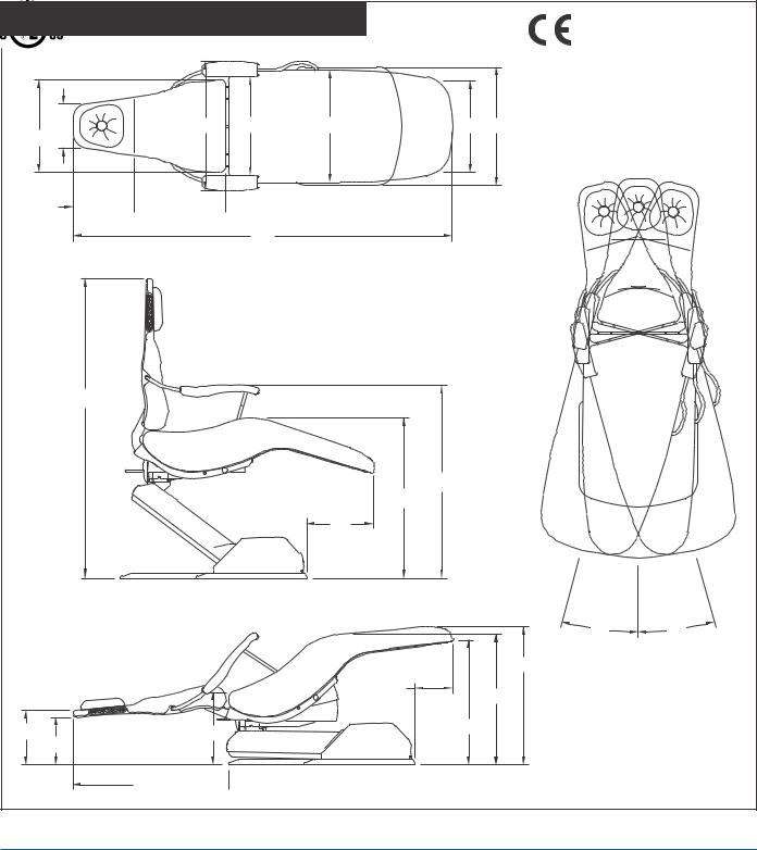
J-Chair Dimensions
Class 1, Type B Medical Equipment for Ordinary Use
|
|
|
|
|
|
with Respect to Electric |
|
|
|
|
|
|
Shock, Fire, Mechanical and |
|
|
|
|
|
|
Other Specified Hazards |
9" |
27.38" |
20.63" |
23" |
18" 24" |
53HN |
Only in Accordance with UL |
RISK |
2601-1 and CAN/CSA |
|||||
|
|
|
|
|
|
|
19" |
|
|
|
|
CLASS |
No. 601.1. |
|
|
|
|
2G |
12.25"  18"
18"
76"
63"
41.75" |
36" |
17" |
|
15º |
15º |
|
30" |
|
7" |
28.5" |
|
|
|
11" |
15" |
26" |
|
9.75" |
|
31.5"
 38"
38"
2 Installation, Operation and Care Manual
")
Section I Introduction
Specifications
Electrical Power: 15 amp fused Branch Circuit |
Shipping Weight: |
J-Chair |
V-Chair |
115 VAC, 50/60 Hz, as applicable |
Chair Carton: |
320 lbs. |
310 lbs. |
220 VAC, 50/60 Hz, as applicable |
Upholstery Package: |
60 lbs. |
60 lbs. |
V-Chair Dimensions
21"  8"
8"
4"
67"
11"
9.75"
27.38" 20.63" |
23" |
18" 24" |
53HN |
RISK |
|||
|
|
|
CLASS |
|
|
|
2G |
20"
76"
5" 11" 

4"
41.75"
36"
17"
30"
7"

28.5"
15" |
26" |
Class 1, Type B Medical Equipment for Ordinary Use
with Respect to Electric Shock, Fire, Mechanical and Other Specified Hazards Only in Accordance with UL 2601-1 and CAN/CSA
No. 601.1.
15˚ 15˚
31.5" 
 38"
38"
J-Chair/V-Chair 3
Section II Pre-installation |
J-Chair®/V-Chair™ |
Read/Review Instructions
To ensure proper installation, carefully read all the instructions contained in this manual paying close attention to all warnings, cautions and notes.
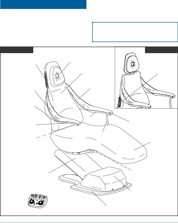
Before starting installation procedures, please review the illustration below to become familiar with the components of the DentalEZ J/V-Chair.
After the J/V-Chair is installed, please review the features, operation procedures and care guidelines with the doctor's staff. Then leave this manual in the doctor's office for the staff's future reference.
— NOTE —
Most instructions/illustrations depict only the J-Chair but similarly pertain to the V-Chair.
J-Chair |
|
V-Chair |
Back Switches |
Headrest |
|
|
Back |
|
|
|
|
|
Chair Back |
Switches |
|
|
|
Arm Sling |
Arm Sling |
|
|
|
|
|
|
1 |
|
|
2 |
|
|
3 |
Armrest |
|
4 |
|
A |
|
|
B |
|
|
|
|
|
Armrest |
Driven Arm |
Floating Arm |
|
|
|
|
|
Chair Brake |
Drive Arm |
|
|
Chair Seat |
|
(behind seat) |
|
|
Chair Base |
|
Model/Serial No. |
|
(front of seat |
|
(Cantilever Section) |
|
|
|
mount casting) |
|
|
|
|
Foot Control |
|
Base (Pump) |
|
|
Cover |
|
Chair Base Plate |
|
4 Installation, Operation and Care Manual
Section II Pre-installation
Unpacking
Tools Required:
•Pliers
•1/2" Socket and Ratchet
Chair Carton
1.Using pliers, remove the staples that secure the shipping carton to the wooden pallet.
2.Remove the carton and packing inserts from the pallet by lifting up.
3.Using a 1/2" socket and ratchet, remove the four bolts that secure the chair base to the shipping pallet.
— CAUTION —
If the chair is equipped with the air glide option, be careful not to tear the air caster when sliding the chair off the pallet and during placement of the chair.
4.Grasp the chair mount casting and slide the chair off the pallet.
— WARNING —
The J/V-Chair is shipped with a retaining strap to secure the base mechanism. DO NOT REMOVE this strap until the chair is out of the carton and in its position on the floor.
Upholstery Carton
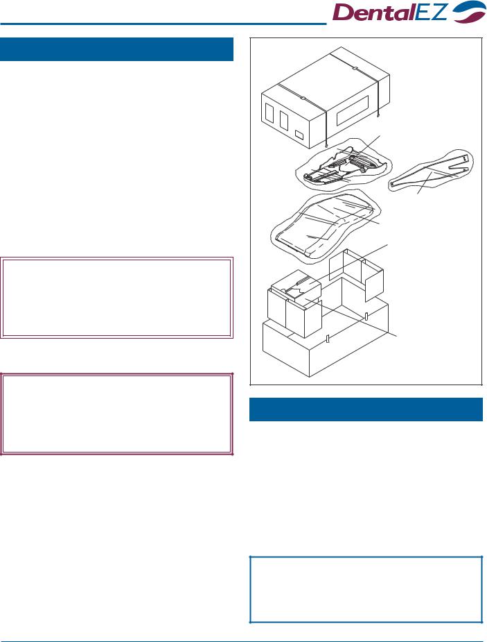
Remove and set aside the following items from the J/V-Chair upholstery assembly packaging:
•Upholstered Back Assembly
•Sling Assemblies
•Upholstered Seat
•Upholstered Armrests
•Headrest
•Optional Foot Control
•Any ordered Options
•Hardware Package
Upholstery |
Carton |
Upholstered |
Back Assembly |
Sling Assemblies |
Upholstered Seat |
Chair Controls/ |
Headrest/ |
Options/ |
Hardware |
Package |
Upholstered |
Armrests |
Chair Placement
1.Taking into consideration the J/V-Chair's specifications (found on Pages 2 and 3), position the chair in its permanent location on a smooth, hard and level floor.
NOTE: Make sure the chair is placed where nothing will interfere with its movement.
2.Remove the retaining strap that secured the base mechanism during shipment.
— NOTICE —
For any questions about an order, please contact a DentalEZ Equipment customer service representative at 1-866-DTE-INFO.
J-Chair/V-Chair 5
Section III Installation |
J-Chair®/V-Chair™ |
|
|
— WARNING —
DO NOT CONNECT the chair POWER cord until all shipping hardware is removed.
Tools Required:
•Phillips Screwdriver
•Flat-head Screwdriver
•9/16" Socket and Ratchet
•5/32" Allen Wrench
Preparing Chair
Chair Back Switches
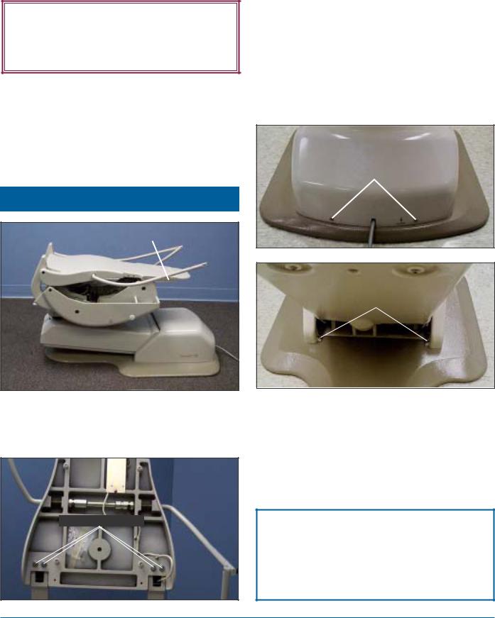
1.Lift up the chair back casting and attach the chair back using four 9/16" hex bolts and lock washers.
9/16" Hex Bolts
2.Connect the chair power. (The chair will emit two short beeps and the LEDs in the two back switch assemblies will light up to indicate the chair is on.)
3.On one side of the chair back, press the switch with the up arrow between the 3 and 4 buttons to raise the chair’s base to its full up position.
FRONT VIEW
Phillips-head Screws
REAR VIEW
Phillips-head Screws
4.Using a Phillips screwdriver, remove the four screws that secure the base cover. (See photos above.)
5.Gently lift off the base cover and set it aside.
NOTE: The base cover remains off the chair until installation is complete.
— NOTICE —
The hydraulic system is shipped with a plug in the reservoir to prevent spillage during shipment. This plug MUST be removed prior to operating the chair.
6 Installation, Operation and Care Manual

Section III Installation
Rubber
Shipping
Plug
6.Remove the rubber shipping plug from the reservoir vent hole.
7.Leave the plug on top of the reservoir cap for future use if necessary.
8.Make sure the stationary arm is on the specified side of the chair.
NOTE: If arm reversing is necessary, proceed with the following opposite arm conversion instructions:
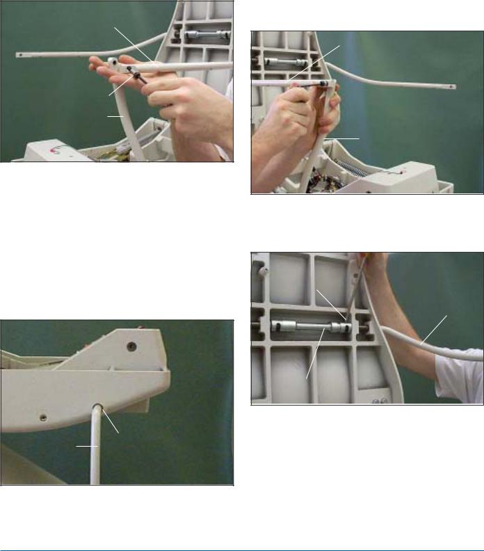
Opposite Arm Conversion
NOTE: The pictures show changing the driven arm from the left side to the right side of the chair. The steps below are for changing either side.
1.Make certain the chair back is in its full upright position.
2.Remove the decorative plastic cap that covers the hole on the opposite side of where the drive arm goes into the seat mount casting.
3.Flip the floating arm all the way up.
Floating Arm
Control
5/16" Slotted Sleeve
Screw
4.Remove the 5/16" slotted screw from the slot on the control sleeve that holds the floating arm.
5.Rotate the floating arm forward until it aligns with the driven arm.
6.Align the hole in the control sleeve with the threaded hole in the arm and install the 5/16" slotted screw that was removed in Step 4.
NOTE: This locks both arms and makes conversion easier.
Floating Arm |
5/16" Slotted |
|
|
|
Screw |
Driven Arm
Drive Arm
Align Arms
Plastic Cap
J-Chair/V-Chair 7
Section III Installation |
J-Chair®/V-Chair™ |
|
|
7.Using a 5/32" Allen wrench, remove the shoulder screw, bushing and washer that holds the driven arm to the drive arm.
Old Driven Arm
Position
Shoulder Screw,
Bushing & Washer
Old Drive Arm
Position
8.Rotate the drive and driven arms down towards the floor.
9.Pull the drive arm out of the hole in the seat mount casting.
NOTE: The drive arm should only come out of the seat mount casting when it is pointing to the floor. A pin in the casting fits into the groove on the arm and prevents it from pulling out of the casting when the arm is rotated up.
Drive Arm |
Seat Mount Casting |
Hole |
10.Push the drive arm, with it pointed toward the floor, into the hole on the opposite side of the seat mount casting.
11.Rotate the drive arm up, and make sure it will not pull out.
12.Rotate the two armrests until the hole in the driven arm lines up with the threaded hole in the drive arm.
New Driven Arm
Position
 Shoulder Screw,
Bushing & Washer
New Drive Arm
Position
13.Install the shoulder screw, bushing and washer that was removed in Step 7, placing the washer on the outside.
5/16" Slotted
Screw Old
Driven
Arm
Control Sleeve
14.Remove the 5/16" slotted screw that holds the old driven arm to the control sleeve.
15.Rotate the old driven arm back and install the 5/16" slotted screw into the arm through the slot in the control sleeve. (This arm is now the floating arm.)
8 Installation, Operation and Care Manual
Section III Installation
Control Sleeve |
New |
|
Floating |
|
Arm |
5/16" Slotted |
|
Screw |
|
NOTE: Make sure that when the new floating arm is rotated forward, it lines up with the new driven arm.
16.Place the plastic cap into the original drive arm hole in the seat mount casting.
of the additional controller follow the instructions supplied with the control package. If an auxiliary controller is added, the DIP switch settings on the main control board will need to be set before the controller is recognized (See the DIP Switch Settings, Page 25.)
Auxiliary Controller Options
Foot Control
The foot control harness must be routed through the cord-retaining bracket, which is located underneath the cantilever section. (For more information, refer to the instructions supplied with the foot control package.)
Delivery Units
Install chair-mounted and Magellan-style delivery units according to the manufacturer's instructions supplied with the unit.
Unit Mounted Touchpad
A touchpad can be mounted on the delivery head or assistant's arm of an aXcs® chair mounted unit. (For more information, refer to the instructions supplied with the touchpad control package.)
Chair Controls
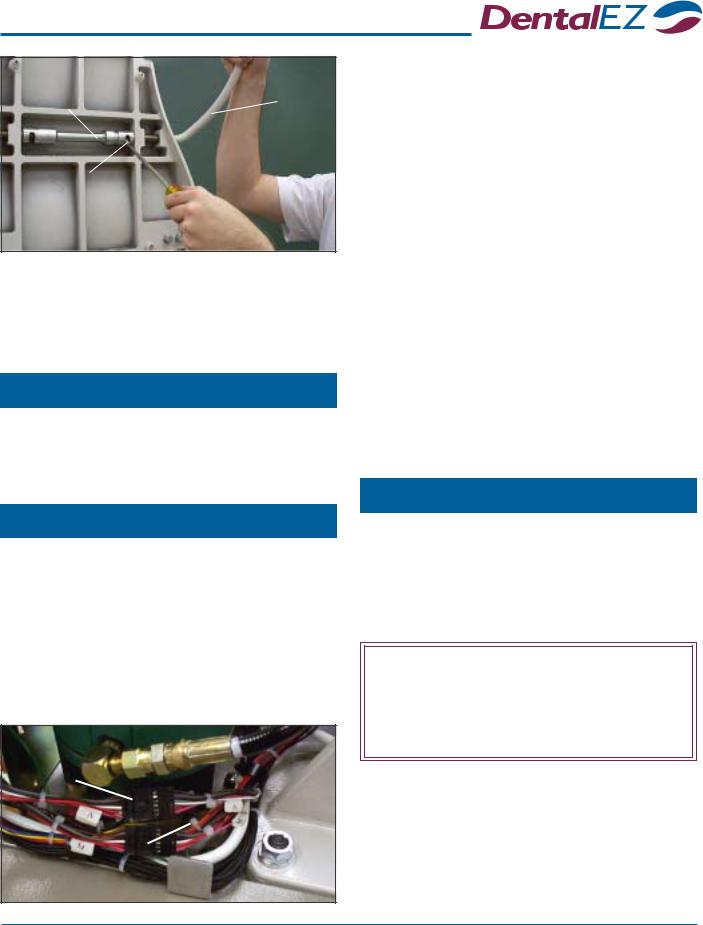
The J-Chair’s (Model J-3) primary controller is located on the chair back's head rest area with switches on both sides. The V-Chair’s primary controller is located on both sides of the lower back. The connections for this controller are labeled M (main) on the chair wiring harness. One controller can be added to the chair and should be attached to the chair wiring labeled A (auxiliary). For installation
Auxiliary Wiring
Harness
Connector Main Wiring
Harness
Connector
Options
Air Glide
NOTE: If the air glide option was ordered, the air regulator was attached to the base chassis prior to shipment of the chair.
— IMPORTANT —
For proper air glide operation, the floor MUST BE LEVEL and have a smooth, hard and non-obstructive surface.
1.Place the J/V-Chair on a smooth, hard and level (vinyl, tile or terrazzo type) floor.
2.Connect the air glide tubing to a regulated air supply source (usually 80 PSI on most dental units).
J-Chair/V-Chair 9
Section III Installation |
J-Chair®/V-Chair™ |
— CAUTION —
To prevent air caster damage, DO NOT EXCEED 20 PSI. If bouncing should occur, reduce the air pressure as required.
Air Regulator
Air Glide
Tubing
3.Adjust the air regulator located on the base chassis to 15-20 PSI.
4.Actuate the air regulator toggle switch at the rear of the chair on the base cantilever section cover.
 Air Regulator
Toggle Switch
5.Check for proper air glide operation.
6.Make sure the doctor and staff receive proper air glide feature operation instructions. (See Operation, Optional Features, Page 22.)
Light Receptacle
An AC power connector is supplied with each J/V- Chair to accommodate a light (up to 2 amps). The connector is located on the right side of the chair mount. A light having the proper connector can attach directly to the AC power connector, or a light receptacle plug can be installed. To install the J/V-Chair light receptacle option, proceed with the following steps:
1.Raise the seat to its full UP position.
2.Disconnect the chair power.
3.Feed the light receptacle cord through the slot in the front cover of the seat casting.
Light Receptacle
Cord
4.Connect the light receptacle connector to the chair AC power connector.
5.Using a 1/4" clamp and #10-32 x 3/8" screw and lock washer, secure the light receptacle cord to the chair mount casting.
AC Power |
Light |
Connector |
|
Chair |
Receptacle |
Power |
Connector Clamp |
Cord |
|
6.Arrange the chair power cord so there is no slack and make sure the cord does not come in contact with any of the chair's moving parts. Then, if necessary, adjust the clamp that secures the chair power cord.
10 Installation, Operation and Care Manual
Section III Installation
Auxiliary Light Relay
NOTICE: There are three different light relays that can be installed depending on the application:
•The 120 VAC relay is used with a light that requires a 120 VAC connection to its transformer.
•The 220 VAC relay is used with a light that requires a 220 VAC (single phase) connection to its transformer.
•The 24 VAC relay is used with a DentalEZ aXcs® Operatory Light and power module package. The aXcs light connects directly to the aXcs power module.
— CAUTION —
Make sure the voltage and amperage ratings for the light relay installed is correct for the light package. (The relay ratings are printed on the side of the relay.)
1.Raise the chair base to its full UP position.
2.Disconnect the chair power.
3.Review the wire schematic printed on the side of the relay. (Take note of the positions for the DC positive (+) and negative (-) connections.
There are two male 3/16" spade connectors on the relay.)
4.Using the screws and nuts supplied with the auxiliary light relay, mount the relay to the main control board mounting plate.
5.Plug in the DC relay wires according to the schematic. The red/white positive (+) and black negative (-) wires with female 3/16"
spade connectors are located on the wiring harness above the relay.
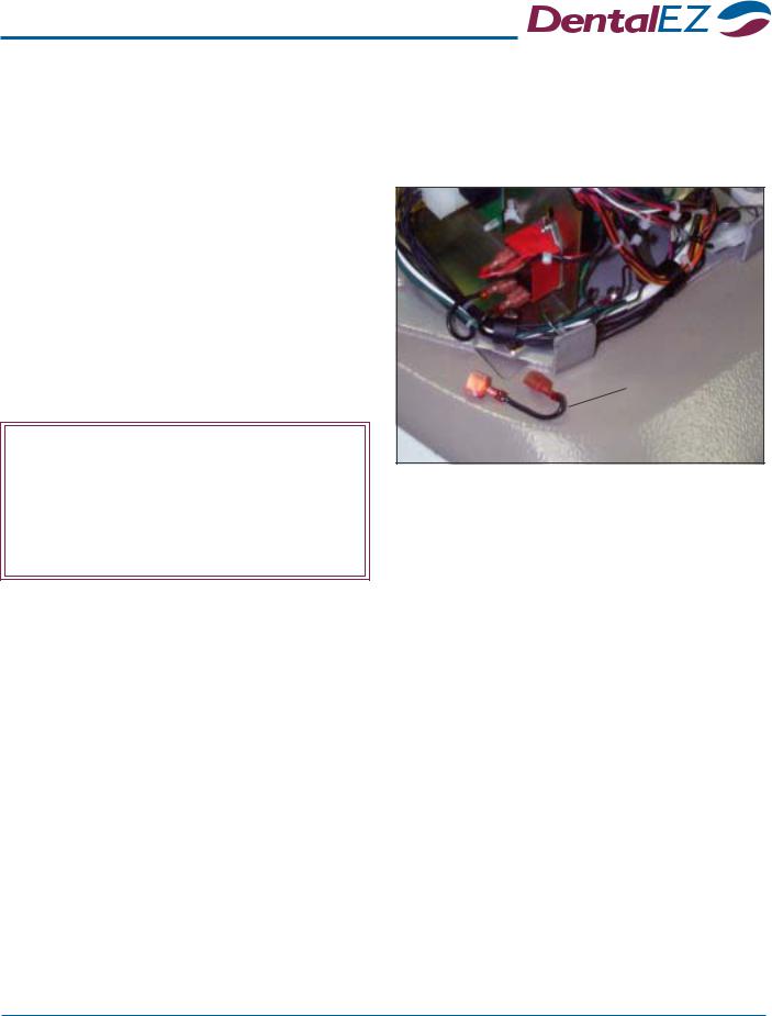
6.For 120/220 VAC connection do the following steps:
 Auxiliary
Light Relay
Chair Wiring
Jumper
120/220VAC
a.Locate the jumper in the black AC wiring below the relay and remove the short black jumper with the male 1/4" spade connectors.
b.Plug the two female 1/4" spade connectors into the male 1/4" spade connectors on the relay.
c.Proceed to Step 8.
7.For 24 VAC connection do the following steps:
a.Remove the four #10 screws that secure the utility service center (USC) cover and take off the cover.
NOTE: The aXcs light has two AC lines for low and high light intensities. The relay turns on and off the common wire to the light’s two AC lines.
J-Chair/V-Chair 11
Loading...