


Master Control Panel
User Manual

Table of Contents
Section I Introduction
Main Control Box .................................................................................................................... 2
Relay Box Connection (Single/Dual Vacuum Pump) ...........................................................3
Vacuum Pump Relay Box Wiring Schematic .......................................................................4
Master Water Control Valve Connection .............................................................................. 5
Air Compressor Remote Connections ................................................................................. 6
Rocker Switch Installation .................................................................................................... 6
Section II Wiring Schematics
MP - 100 / 300 ........................................................................................................................ 7
MP - 400 ................................................................................................................................8
MP - 700 ................................................................................................................................ 9
MP - 900 ...............................................................................................................................10
MP - 1000 ..... ...........................................................................................................................11
MP - 1100... .............................................................................................................................12
MP - 2000 ..............................................................................................................................13
MP - 2200 ..............................................................................................................................14
Limited Warranty ...............................................................................................................15
www.DentalEZ.com 866-DTE-INFO (opt 4)
www.DentalEZ.com
1
1

Section I Installation
Master Control Panel User Manual
Main Control Box
WARNING
Before proceeding with any electrical installation,
comply with and maintain all applicable local electrical
codes(s) and regulations.
NOTICE
All wiring between the main control box and equipment
should be Class B, low-voltage. In most cases, a conduit
is not required when using this type of wiring.
1. Position the main control mounting box so
that the master control panel switches are
easily visible and in a convenient location
(near the oice entrance/exit).
2. Once the main control mounting box is in position, secure it using the brackets provided.
NOTE: To ensure proper installation of the nished
master control panel, the mud ange must be
recessed by dray wall thickness.
3. Install the main control box wires as follows:
a. Using a hammer and pliers, remove the
appropriate knock-out from the main
control mounting box.
b. Fit a nylon grommet in the knock-out.
(This protects the wires from chaing and
shorting out.)
c. Run the appropriate wires to their respec-
tive equipment location, then connect the
wires according to the instructions on the
following pages.
4. After all wiring connections are completed
correctly, position and secure the master
control panel to the main control box using
the screws provided.
Wiring Chart
Model No. No. of Wires Wire Under 500 Ft. Wire Over 500 Ft.
CV-101 3 18 AWG 16 AWG
CV-102 3 18 AWG 16 AWG
MC-201 6 18 AWG 16 AWG
MC-202 6 18 AWG 16 AWG
Air Compressor 3 18 AWG 16 AWG
MWCV Solenoid Valve 2 18 AWG 16 AWG
MWCV Transformer 2 18 AWG 16 AWG
www.DentalEZ.com
www.DentalEZ.com
866-DTE-INFO (opt 4)
2
2

Section I Installation
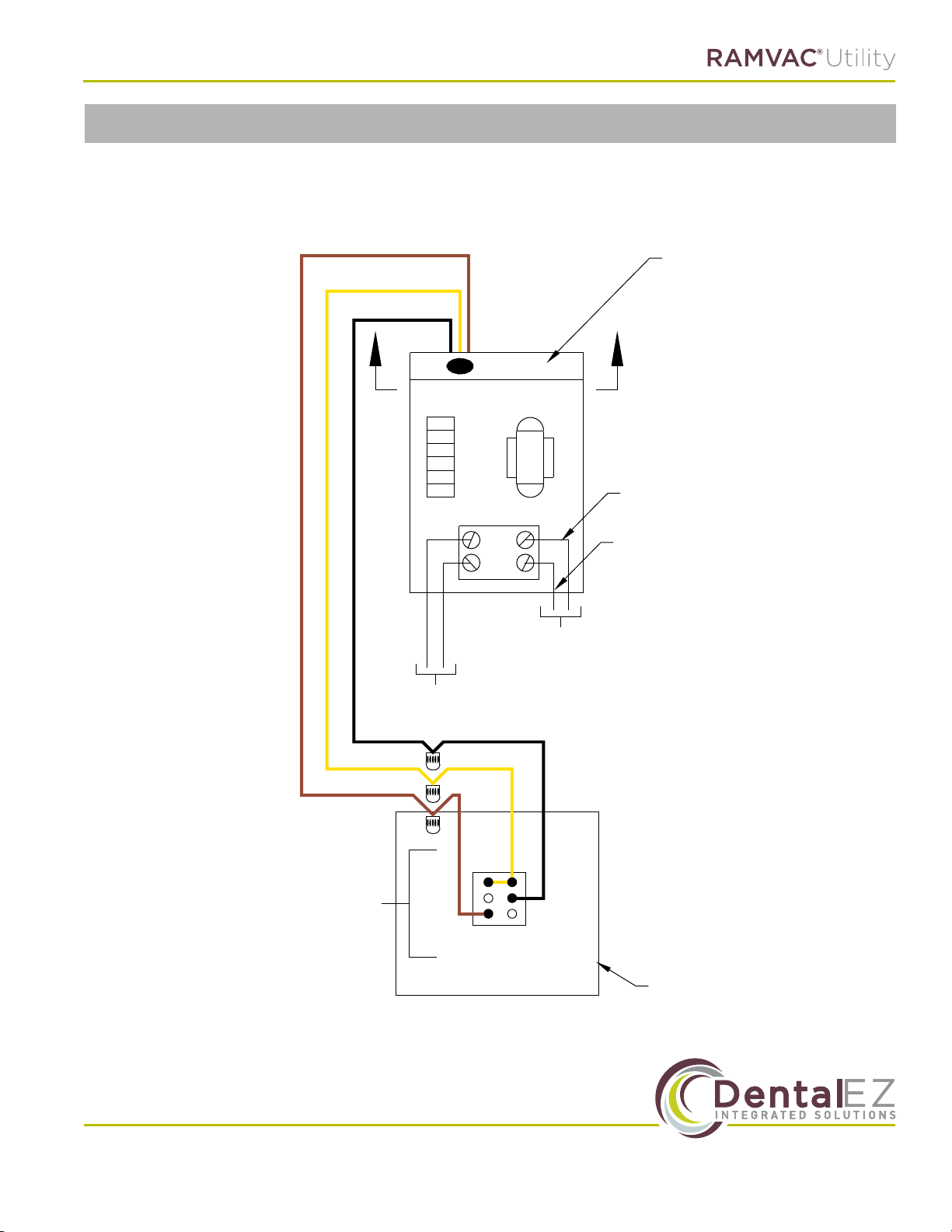
Relay Box Connection
Single/Dual Vacuum Pump
(All Panes, Except Turbine)
WARNING
Before proceeding with the single / dual vacuum pump
relay box connection, make sure the electrical power
supply to the vacuum pump is turned OFF.
NOTE: For dual vacuum pump relay box to the
main control box connection, Steps 1 through 8
listed below must be performed for each vacuum
pump. Refer to the vacuum pump relay box wiring
schematic on the next page.
NOTE: For vacuum pump relay boxes with factory
installed yellow, black and brown wires, it is not
necessary to perform Steps 1 through 8 below.
1. Loosen the top and bottom retainer screws
from the vacuum pump relay box and remove
the cover.
CAUTION
Before making any wiring connections to the main control
box, the vacuum unit should be completely installed.
NOTICE
All pumps ( single or dual) must have three, low-voltage
wires installed from the top of each relay box going to
the main control box in order to operate the master
control panel lighted ON / OFF switches.
2. Remove the black strain relief grommet from
the top of the vacuum pump relay box.
3. Place the tap connector slot over the yellow
transformer wire, and insert the brown wire
into the end of the tap connector.
4. Squeeze the metal connector tight, and snap
the attached cover in place.
5. Route the brown wire out through the strain
relief grommet hole along with the yellow and
black wires.
6. Reinstall the strain relief grommet around the
yellow, black and brown wires.
7. Reinstall the relay box cover and tighten the
top and bottom retainer screws.
8. Run and connect the low-voltage wires to the
main control panel mounting box according to
the applicable wiring schematic in Section II,
Wiring Schematics.
www.DentalEZ.com 866-DTE-INFO (opt 4)
www.DentalEZ.com
3
3

Section I Installation
Vacuum Pump Relay Box Wiring Schematic
MOTOR
Master Control Panel User Manual
BLUE
BLACK
GREEN
& YELLOW
BLACK
BROWN
RED
WHITE
0 1 2 3 4 5 6
BROWN
& WHITE
BLACK
BROWN
BLUE
YELLOW
BLACK
L2/N
L1
BROWN
PURPLE
GREEN
& YELLOW
LIGHT BLUE
PN: 64529265_E
October, 2017
www.DentalEZ.com
www.DentalEZ.com
866-DTE-INFO (opt 4)
4
4

Section I Installation
Master Water Control Valve Connection
(With 24-Volt Lighted Control Switch)
WARNING
To prevent any chance of electrical shock, always
disconnect power when indicated.
NOTICE
When using low voltage to operate the master water
control valve (MWCV), a 115-volt electrical receptacle for
the MWCV "plug-in" transformer must be supplied.
1. Make sure all power is properly disconnected.
2. Remove the MWCV from the shipping contain-
er or locate a previously installed MWCV in the
oice.
3. Dismantle the coil assembly.
4. Replace the 115-volt coil with the 24-volt coil
included in the kit.
5. Connect the two low-voltage wires from the
transformer according to the applicable master
control panel wiring schematic in Section II.
WARNING
Do not plug in the transformer until all electrical
connections are complete.
6. Test the MWCV and transformer as follows:
a. Turn the light switch to the OFF position.
(The light should be o.)
b. Turn the light switch to the ON position.
(The light should be on.)
c. When the switch is activated, the MWCV
should make a clicking sound, which indicates the valve is working properly.
d. If the light fails to come on, or if the MWCV
fails to function, check all connections
referring to the applicable master control
panel wiring schematic in Section II.
NOTE: If a light stays ON while the switch is
in the OFF position, simply reverse the wires
numbered 2 and 3 on the switch. The light
should then operate correctly.
www.DentalEZ.com 866-DTE-INFO (opt 4)
www.DentalEZ.com
5
5

Section I Installation
S1 Electrols Terminals
Air Compressor Remote Connection
WARNING
To prevent any chance of electrical shock, always
disconnect power when indicated.
1.
Disconnect power to the air compressor.
2. Mount the compressor relay box near the
junction box on the air compressor.
3. Connect the power source supply lines to L1
and L2 on the compressor relay box for new
installation.
Master Control Panel User Manual
4. Connect conduit from the compressor relay
box to the junction box.
5. Connect the two lines from T1 and T2 to the
two compressor power lines in the junction
box.
6. Run and connect low-voltage wires to the
main control box according to the applicable
master control panel wiring schematic in
Section II.
NOTE:
the power source supply lines from the
junction box.
When connecting a pump, replace the VAC switch
in the master control panel with the loose switch
supplied.
Refer to the schematic on the right for rocker
switch installation in the following panels:
PANEL PART #
MP - 300 64652017
MP - 1000 64568077
MP - 2000 64568110
MP - 2200 64568111
MP - 1000A 64568171
MP - 2000A 64568174
MP - 2200A 64568175
Connect to an S1 Electrols as follows:
Terminal #4 - connect to S1 terminal "G"
Terminal #3 - connect to S1 terminal "H"
Terminal #2 - connect to S1 terminal "F"
For existing installation, rst remove
Rocker Switch Installation
S1 Electrols Terminals
F
H
G
3
2
4
VAC Switch
www.DentalEZ.com
www.DentalEZ.com
866-DTE-INFO (opt 4)
6
6

Section II Wiring Schematics
MP - 100 / 300
One Switch, Single Vacuum
Brown
Yellow
Black
Line Voltage
(To Source)
L2
T2
L1
T1
Load
(To Vacuum Pump)
Vacuum Pump
Relay Box
Wall-Mounted Switches
Shown from
Back of Switch Plate
Vacuum
Junction Box
www.DentalEZ.com 866-DTE-INFO (opt 4)
www.DentalEZ.com
7
7

Section II Wiring Schematics
Two Switch, Dual Vacuum
Master Control Panel User Manual
MP - 400
ON/OFF Switches
Mounted on Dual Cabinet
Brown
Yellow
Black
Line Voltage
(To Source)
OFF
L2
T2
L1
T1
(To Vacuum
ON
Load
Pump)
Vacuum
Pump
Relay
Box
Brown
Yellow
Black
Line Voltage
(To Source)
ON
OFF
L2
T2
L1
T1
(To Vacuum
Vacuum
Pump
Relay
Box
Load
Pump)
Brown
Yellow
Black
Vacuum Pump
Relay Box
www.DentalEZ.com
www.DentalEZ.com
Vacuum 1
Vacuum Unit Panel Mounted Switches
(Same Connection as Back View)
ON
OFF
Brown
Yellow
Black
ON
OFF
Wall-Mounted
Switches
Shown from
Back of
Switch Plate
Junction Box
NOTE:
Vacuum 2
Using the circuit depicted in the diagram above, either switch will turn the vacuum pumps on. To wire pumps so that either
switch will turn the vacuum pumps o, use
the circuit shown in the diagram to the left.
866-DTE-INFO (opt 4)
8
8
Section II Wiring Schematics
One Switch, Air Compressor
MP - 700
Brown
Yellow
Black
Line Voltage
(To Source)
L2
T2
L1
T1
Black
Load
(To Air Compressor)
Compressor
Relay Box
Red
Wall-Mounted Switches
Shown from
Back of Switch Plate
Air Compressor
Junction Box
www.DentalEZ.com 866-DTE-INFO (opt 4)
www.DentalEZ.com
9
9

Section II Wiring Schematics
Three Switch, (Dynamic Dry) Single Vacuum, Air Compressor, Water
Solenoid Valve
Main Water Control
Master Control Panel User Manual
MP - 900
In
AC
Coil
24V
Coil
24V
Plug In Transformer
Brown
213
Air Comp. Water
Load (To Compressor)
Line Voltage (To Source)
Compressor Relay Box
Shown from
Wall-Mounted Switches
Vacuum
Back of Switch Plate
Red
Black
23123
Air
Out
T1
L1
L2 T2
Black
Yellow
Relay Box
Dynamic Dry
T1
L1
L2 T2
In
43143
Air
Load
(To Dynamic Dry)
1
Vac
Out
In
1
Vac
www.DentalEZ.com
www.DentalEZ.com
(Wall Mount Near Dynamic Dry)
(To Source)
Line Voltage
Brown
Yellow
Black
866-DTE-INFO (opt 4)
10
10

Section II Wiring Schematics
Three Switch, Single Vacuum, Air Compressor, Water
Solenoid Valve
Main Water Control
Plug In Transformer
MP - 1000
AC
24V
24V
213
In
Coil
Coil
Water
Brown
Brown
Yellow
Yellow
Black
Black
Air Comp.
Load (To Compressor)
Line Voltage (To Source)
Compressor Relay Box
Red
L2 T2
Black
T1
L1
23123
Air
Out
In
43143
Air
1
Vac
Out
In
1
Vac
Vacuum
Shown from
Back of Switch Plate
Wall-Mounted Switches
Relay Box
Vacuum Pump
www.DentalEZ.com 866-DTE-INFO (opt 4)
www.DentalEZ.com
11
11

Section II Wiring Schematics
Four Switch, Dual Vacuum, Air Compressor, Water
Red
Black
Load (To
Master Control Panel User Manual
MP - 1100
Compressor)
Relay Box
Compressor
to the Numbers on
the Side of the Switches
These Numbers Correspond
Shown from
Wall-Mounted Switches
Back of Switch Plate
(To Source)
1 2 3 4
Air Comp - In
on Valve
From Coil
4 1 3 2
Air Comp - Out
3
Jumper
Using the circuit depicted in the
Brown
T1
L1
L2 T2
Black
Yellow
Line Voltage
Solenoid Valve
diagram above, either switch will turn
the vacuum pumps on. To wire pumps so
that either switch will turn the vacuum
pumps o, use the circuit shown in the
Main Water Control
Plug In
Water Control - In
24V Trans.
Power from
Water Control - Out
NOTE:
diagram to the left.
Transformer
ON
OFF
Vac. #2 - In
1 3 4 1 3 4
Vac. #1 - In
Vac. #2 - Out
4 3 2 4 3 2 2 4
Vac. #1 - Out
Vacuum 1 Vacuum 2 Water Air Comp.
ON
OFF
Black
Yellow
Brown
(Same Connection as Back View Below)
Vacuum Unit Panel Mounted Switches
ON
OFF
Black
Yellow
Brown
www.DentalEZ.com
www.DentalEZ.com
Relay Box
Vacuum Pump
to the Numbers on the
Terminal in the Relay Box
These Numbers Correspond
12
12
Black
Yellow
Brown
(Same Connection as Back View)
Vacuum Unit Panel Mounted Switches
ON
OFF
Relay Box
Vacuum Pump
Black
Yellow
Brown
866-DTE-INFO (opt 4)

Section II Wiring Schematics
Two Switch, Single Vacuum, Air Compressor
MP - 2000
Brown
Yellow
Black
Relay Box
Compressor
Relay Box
Vacuum Pump
Load (To
Red
T2
L2
Black
T1
L1
Load (To
Line Voltage
Compressor)
Vacuum Pump
(To Source)
Air
Out
In
Air
(To Source)
Line Voltage
23123
43143
Vacuum Air Comp.
1
Vac
Out
In
1
Vac
Shown from
Back of Switch Plate
Wall-Mounted Switches
Blue
Blue
T1
T2
L1
L2
Black
Yellow
Brown
www.DentalEZ.com 866-DTE-INFO (opt 4)
www.DentalEZ.com
13
13

Section II Wiring Schematics
Three Switch, Dual Vacuum, Air Compressor
Relay Box
Red
T2
L2
Load (To
Black
Compressor)
T1
L1
(To Source)
Line Voltage
Brown
Compressor
Black
Yellow
Master Control Panel User Manual
MP - 2200
23123
Air
Out
In
Air
43143
Shown from
1
Vac
Out
In
1
Vac
Wall-Mounted Switches
Back of Switch Plate
Vacuum Unit Panel Mounted Switches
(Same Connection as Back View Below)
ON
ON
Brown
Brown
OFF
OFF
Using the circuit depicted in the
diagram above, either switch will turn
the vacuum pumps on. To wire pumps so
that either switch will turn the vacuum
pumps o, use the circuit shown in the
Vacuum 1 Vacuum 2 Air Comp.
231
Vac
Out
Black
Yellow
431
In
Vac
Relay Box
Vacuum Pump
Black
Yellow
ON
OFF
Brown
(Same Connection as Back View)
Vacuum Unit Panel Mounted Switches
ON
OFF
Brown
NOTE:
Black
Yellow
Black
Yellow
diagram to the left.
Relay Box
Vacuum Pump
www.DentalEZ.com
www.DentalEZ.com
14
14
866-DTE-INFO (opt 4)

Limited Warranty
Master Control Panel
DentalEZ and its employees are proud of the products we provide to the dental community. We stand
behind these products with a warranty against defects in material and workmanship as provided below.
In the event that you experience diiculty with the application or operation of any of our products,
please contact our technical service department at our expense at (866)DTE-INFO.
If we cannot resolve the issue by telephone, we will arrange for a representative to contact you or sug-
gest that the product be repaired by a dealer service technician.
If product repair or return is required, we will provide you with a Return Authorization number and ship-
ping instructions to return the product to the proper facility. If the product is under warranty we will ask
you to provide proof of purchase such as a copy of your invoice. Please be sure to include the Return
Authorization number on the package you are returning. Products returned without a return authorization number cannot be repaired.
Freight costs for product returns are the responsibility of the customer. Products under warranty will be
repaired or replaced, at our sole discretion, and returned at our expense. Products outside the warranty
limits will be repaired and returned with costs invoiced to the customer. We are not responsible for ship-
ping damages. We will, however, help you le a claim with the freight carrier. Written repair estimates are
available.
DentalEZ warrants the Master Control Panel to be free of defects in material and workmanship, under
normal usage, for a period of two (2) years from date of installation.*
Please note the following additional terms of our warranty and return policy:
• Warranties cover manufacturing defects only and do not cover defects resulting from abuse, improper handling, cleaning, care or maintenance, normal wear and tear or non-observance of operating, maintenance or installation instructions. Failure to use authorized parts or an authorized repair
facility voids this warranty.
• Liability is limited to repair or replacement of the defective product at our sole discretion. All
other liabilities, in particular liability for damages, including, without limitation, consequential or
incidental damages are excluded.
• THIS WARRANTY IS IN LIEU OF ALL OTHER WARRANTIES, EXPRESSED OR IMPLIED, INCLUDING ANY
IMPLIED WARRANTIES OF MERCHANTABILITY OR FITNESS FOR A PARTICULAR PURPOSE. NO EMPLOYEE, REPRESENTATIVE OR DEALER IS AUTHORIZED TO CHANGE THIS WARRANTY IN ANY WAY OR
TO GRANT ANY OTHER WARRANTY.
WARRANTY REPAIRS: Parts repaired or replaced on a product that is in warranty will be warranted for the
duration of that product’s original warranty.
NON-WARRANTY REPAIRS: The warranty on parts either repaired or replaced on an out-of-warranty
product will cover the repaired part only and will be for the time frame of a new parts warranty period.
PRODUCT RETURN: Opened products or product returns more than a year old cannot be returned for
credit. There will be a 15% ($25.00 minimum) restocking charge on all items authorized for return.
*Provided conditions dened in the instruction manual are met.
DentalEZ and RAMVAC are registered trademarks of DentalEZ, Inc.
SlugBuster is a trademark of DentalEZ, Inc.
© 2017 DentalEZ Alabama, Inc.
www.DentalEZ.com 866-DTE-INFO (opt 4)
www.DentalEZ.com
15
15

© DentalEZ® Alabama, Inc.
Printed in USA
212 North Main Street
Spearsh, SD 57783
866-DTE-INFO (opt 4)
www.dentalez.com
PN: 64710071D
January, 2018
 Loading...