


J-Chair® (Model J-3)
J-Chair
and V-Chair
™
1
2
3
4
A
B
V-Chair
Installation, Operation and Care Manual

Table of Contents
Section I Introduction
J-Chair Dimensions ..............................................................................................................2
Specifications .........................................................................................................................3
V-Chair Dimensions .............................................................................................................3
Section II Pre-installation
Read/Review Instructions ...................................................................................................4
Unpacking............................................................................................................................... 5
Chair Placement ...................................................................................................................5
Section III Installation
Preparing Chair ................................................................................................................. 6-9
Delivery Units .......................................................................................................................9
Chair Controls ......................................................................................................................9
Options ............................................................................................................................. 9-12
Chair Upholstery ......................................................................................................... 12-16
Section IV Features
Standard .............................................................................................................................. 17
Optional .............................................................................................................................. 17
Section V Operation
Manual Positioning............................................................................................................. 18
Automatic Positioning ................................................................................................ 18-20
Controller Functions/Modes........................................................................................... 20
Standard Features .............................................................................................................. 21
Optional Features........................................................................................................ 21-22
Section VI Care
Cleaning ......................................................................................................................... 23-24
Disinfecting ......................................................................................................................... 24
Section VII User Service Information
DIP Switch Settings ........................................................................................................... 25
Beep Codes .................................................................................................................. 25-26
LED Codes.................................................................................................................... 27-28
Service Instruction ............................................................................................................ 27
Programming Travel Limits......................................................................................... 29-30
Control Valve Speed Adjustment.............................................................................. 31-32
Section VIII Parts List ................................................................................... 33
Product Support Services ............................................................................ 34
Wiring Schematic
Installation, Operation and Care Manual
J-Chair/V-Chair
1

Section I Introduction
J-Chair®/V-Chair™
This manual contains the installation, operation and
care instructions and user service information for the
®
DentalEZ
J-Chair® (Model J-3) and V-Chair.
J-Chair Dimensions
19"
9"
12.25"
27.38"
18"
20.63"
76"
23"
The DentalEZ J-Chair and V-Chair are designed to
provide many years of trouble-free service when
installed, operated and cared for according to the
procedures set forth in this manual.
Class 1, Type B Medical
Equipment for Ordinary Use
with Respect to Electric
Shock, Fire, Mechanical and
Other Specified Hazards
18"
24"
53HN
RISK
CLASS
2G
Only in Accordance with UL
2601-1 and CAN/CSA
No. 601.1.
11"
9.75"
63"
31.5"
15"
38"
17"
36"
7"
41.75"
26"
28.5"
30"
15º
15º
2 Installation, Operation and Care Manual

Section I Introduction
Specifications
Electrical Power: 15 amp fused Branch Circuit
115 VAC, 50/60 Hz, as applicable
220 VAC, 50/60 Hz, as applicable
V-Chair Dimensions
21"
20.63"
8"
27.38"
20"
76"
5"
11"
4"
4"
23"
Shipping Weight: J-Chair V-Chair
Chair Carton: 320 lbs. 310 lbs.
Upholstery Package: 60 lbs. 60 lbs.
Class 1, Type B Medical
Equipment for Ordinary Use
with Respect to Electric
Shock, Fire, Mechanical and
Other Specified Hazards
18"
24"
53HN
RISK
CLASS
Only in Accordance with UL
2601-1 and CAN/CSA
No. 601.1.
2G
11"
67"
9.75"
1
2
3
4
A
B
41.75"
36"
17"
31.5"
30"
B
A
4
3
2
1
15"
7"
28.5"
26"
15˚
38"
15˚
J-Chair/V-Chair
3

Section II Pre-installation
J-Chair®/V-Chair™
Read/Review Instructions
To ensure proper installation, carefully read all the
instructions contained in this manual paying close
attention to all warnings, cautions and notes.
Before starting installation procedures, please review
the illustration below to become familiar with the
components of the DentalEZ J/V-Chair.
J-Chair
Back Switches
Arm Sling
Armrest
Headrest
After the J/V-Chair is installed, please review the
features, operation procedures and care guidelines
with the doctor's staff. Then leave this manual in
the doctor's office for the staff's future reference.
— NOTE —
Most instructions/illustrations depict only the
J-Chair but similarly pertain to the V-Chair.
Chair Back
Arm Sling
1
2
3
4
A
B
Switches
V-Chair
Back
Floating Arm
Chair Brake
(behind seat)
Chair Base
(Cantilever Section)
Foot Control
Armrest
Driven Arm
Drive Arm
Chair Seat
Model/Serial No.
(front of seat
mount casting)
Base (Pump)
Cover
Chair Base Plate
4 Installation, Operation and Care Manual

Section II Pre-installation
Unpacking
Tools Required:
Pliers
1/2" Socket and Ratchet
Chair Carton
1. Using pliers, remove the staples that secure
the shipping carton to the wooden pallet.
2. Remove the carton and packing inserts from
the pallet by lifting up.
3. Using a 1/2" socket and ratchet, remove the
four bolts that secure the chair base to the
shipping pallet.
— CAUTION —
If the chair is equipped with the air glide
option, be careful not to tear the air caster
when sliding the chair off the pallet and
during placement of the chair.
4. Grasp the chair mount casting and slide the
chair off the pallet.
Upholstery
Carton
Upholstered
Back Assembly
Sling Assemblies
Upholstered Seat
Chair Controls/
Headrest/
Options/
Hardware
Package
Upholstered
Armrests
— WARNING —
The J/V-Chair is shipped with a retaining
strap to secure the base mechanism. DO NOT
REMOVE this strap until the chair is out of
the carton and in its position on the floor.
Upholstery Carton
Remove and set aside the following items from the
J/V-Chair upholstery assembly packaging:
Upholstered Back Assembly
Sling Assemblies
Upholstered Seat
Upholstered Armrests
Headrest
Optional Foot Control
Any ordered Options
Hardware Package
Chair Placement
1. Taking into consideration the J/V-Chair's
specifications (found on Pages 2 and 3),
position the chair in its permanent location on
a smooth, hard and level floor.
NOTE: Make sure the chair is placed where nothing
will interfere with its movement.
2. Remove the retaining strap that secured the
base mechanism during shipment.
— NOTICE —
For any questions about an order, please
contact a DentalEZ Equipment customer
service representative at 1-866-DTE-INFO.
J-Chair/V-Chair
5

Section III Installation
— WARNING —
DO NOT CONNECT the chair POWER
cord until all shipping hardware is removed.
Tools Required:
Phillips Screwdriver
Flat-head Screwdriver
J-Chair
2. Connect the chair power. (The chair will emit
two short beeps and the LEDs in the two back
switch assemblies will light up to indicate the
chair is on.)
3. On one side of the chair back, press the
switch with the up arrow between the 3 and 4
buttons to raise the chairs base to its full up
position.
®
/V-Chair™
9/16" Socket and Ratchet
5/32" Allen Wrench
Preparing Chair
Chair Back Switches
1. Lift up the chair back casting and attach the
chair back using four 9/16" hex bolts and
lock washers.
FRONT VIEW
Phillips-head Screws
REAR VIEW
Phillips-head Screws
4. Using a Phillips screwdriver, remove the four
screws that secure the base cover. (See photos
above.)
9/16" Hex Bolts
6 Installation, Operation and Care Manual
5. Gently lift off the base cover and set it aside.
NOTE: The base cover remains off the chair until
installation is complete.
— NOTICE —
The hydraulic system is shipped with a plug in
the reservoir to prevent spillage during shipment. This plug MUST be removed prior to
operating the chair.

Section III Installation
Rubber
Shipping
Plug
6. Remove the rubber shipping plug from the
reservoir vent hole.
7. Leave the plug on top of the reservoir cap for
future use if necessary.
8. Make sure the stationary arm is on the
specified side of the chair.
2. Remove the decorative plastic cap that covers
the hole on the opposite side of where the
drive arm goes into the seat mount casting.
3. Flip the floating arm all the way up.
Floating Arm
5/16" Slotted
Screw
Control
Sleeve
NOTE: If arm reversing is necessary, proceed
with the following opposite arm conversion instructions:
Opposite Arm Conversion
NOTE: The pictures show changing the driven
arm from the left side to the right side of the chair.
The steps below are for changing either side.
1. Make certain the chair back is in its full
upright position.
Floating Arm
Driven Arm
Drive Arm
4. Remove the 5/16" slotted screw from the slot
on the control sleeve that holds the floating arm.
5. Rotate the floating arm forward until it aligns
with the driven arm.
6. Align the hole in the control sleeve with the
threaded hole in the arm and install the 5/16"
slotted screw that was removed in Step 4.
NOTE: This locks both arms and makes
conversion easier.
5/16" Slotted
Screw
Align Arms
Plastic Cap
J-Chair/V-Chair
7

Section III Installation
J-Chair
®
/V-Chair™
7. Using a 5/32" Allen wrench, remove the
shoulder screw, bushing and washer that holds
the driven arm to the drive arm.
Old Driven Arm
Position
Shoulder Screw,
Bushing & Washer
Old Drive Arm
Position
8. Rotate the drive and driven arms down
towards the floor.
9. Pull the drive arm out of the hole in the seat
mount casting.
NOTE: The drive arm should only come out of
the seat mount casting when it is pointing to the
floor. A pin in the casting fits into the groove on the
arm and prevents it from pulling out of the casting
when the arm is rotated up.
11. Rotate the drive arm up, and make sure it will
not pull out.
12. Rotate the two armrests until the hole in the
driven arm lines up with the threaded hole in
the drive arm.
New Driven Arm
Position
Shoulder Screw,
Bushing & Washer
New Drive Arm
Position
13. Install the shoulder screw, bushing and washer
that was removed in Step 7, placing the
washer on the outside.
5/16" Slotted
Screw
Old
Driven
Arm
Seat Mount Casting
Drive Arm
10. Push the drive arm, with it pointed toward the
floor, into the hole on the opposite side of
the seat mount casting.
8 Installation, Operation and Care Manual
Hole
Control Sleeve
14. Remove the 5/16" slotted screw that holds
the old driven arm to the control sleeve.
15. Rotate the old driven arm back and install the
5/16" slotted screw into the arm through the
slot in the control sleeve. (This arm is now the
floating arm.)

Section III Installation
Control Sleeve
5/16" Slotted
Screw
New
Floating
Arm
of the additional controller follow the instructions
supplied with the control package. If an auxiliary
controller is added, the DIP switch settings on the
main control board will need to be set before the
controller is recognized (See the DIP Switch Settings,
Page 25.)
Auxiliary Controller Options
Foot Control
NOTE: Make sure that when the new floating arm is
rotated forward, it lines up with the new driven arm.
16. Place the plastic cap into the original drive
arm hole in the seat mount casting.
Delivery Units
Install chair-mounted and Magellan-style delivery
units according to the manufacturer's instructions
supplied with the unit.
Chair Controls
The J-Chairs (Model J-3) primary controller is
located on the chair back's head rest area with
switches on both sides. The V-Chairs primary
controller is located on both sides of the lower back.
The connections for this controller are labeled M
(main) on the chair wiring harness. One controller
can be added to the chair and should be attached to
the chair wiring labeled A (auxiliary). For installation
Auxiliary Wiring
Harness
Connector
Main Wiring
Harness
Connector
The foot control harness must be routed through the
cord-retaining bracket, which is located underneath
the cantilever section. (For more information, refer to
the instructions supplied with the foot control package.)
Unit Mounted Touchpad
A touchpad can be mounted on the delivery head or
assistant's arm of an aXcs® chair mounted unit. (For
more information, refer to the instructions supplied with
the touchpad control package.)
Options
Air Glide
NOTE: If the air glide option was ordered, the air
regulator was attached to the base chassis prior to
shipment of the chair.
— IMPORTANT —
For proper air glide operation, the floor
MUST BE LEVEL and have a smooth, hard
and non-obstructive surface.
1. Place the J/V-Chair on a smooth, hard and
level (vinyl, tile or terrazzo type) floor.
2. Connect the air glide tubing to a regulated air
supply source (usually 80 PSI on most dental
units).
J-Chair/V-Chair
9

Section III Installation
— CAUTION —
To prevent air caster damage, DO NOT
EXCEED 20 PSI. If bouncing should occur,
reduce the air pressure as required.
Air Regulator
Air Glide
Tubing
3. Adjust the air regulator located on the base
chassis to 15-20 PSI.
4. Actuate the air regulator toggle switch at the rear
of the chair on the base cantilever section cover.
J-Chair®/V-Chair™
1. Raise the seat to its full UP position.
2. Disconnect the chair power.
3. Feed the light receptacle cord through the slot
in the front cover of the seat casting.
Light Receptacle
Cord
4. Connect the light receptacle connector to the
chair AC power connector.
5. Using a 1/4" clamp and #10-32 x 3/8" screw
and lock washer, secure the light receptacle
cord to the chair mount casting.
Air Regulator
Toggle Switch
5. Check for proper air glide operation.
6. Make sure the doctor and staff receive proper
air glide feature operation instructions. (See
Operation, Optional Features, Page 22.)
Light Receptacle
An AC power connector is supplied with each J/VChair to accommodate a light (up to 2 amps). The
connector is located on the right side of the chair
mount. A light having the proper connector can attach
directly to the AC power connector, or a light receptacle plug can be installed. To install the J/V-Chair
light receptacle option, proceed with the following steps:
AC Power
Connector
Chair
Power
Cord
6. Arrange the chair power cord so there is no
slack and make sure the cord does not come
in contact with any of the chair's moving
parts. Then, if necessary, adjust the clamp that
secures the chair power cord.
Light
Receptacle
Connector
Clamp
10 Installation, Operation and Care Manual

Section III Installation
Auxiliary Light Relay
NOTICE: There are three different light relays that
can be installed depending on the application:
The 120 VAC relay is used with a light that
requires a 120 VAC connection to its
transformer.
The 220 VAC relay is used with a light that
requires a 220 VAC (single phase) connection
to its transformer.
The 24 VAC relay is used with a DentalEZ
®
Operatory Light and power module
aXcs
package. The aXcs light connects directly to
the aXcs power module.
— CAUTION —
Make sure the voltage and amperage ratings
for the light relay installed is correct for the
light package. (The relay ratings are printed
on the side of the relay.)
spade connectors are located on the wiring
harness above the relay.
6. For 120/220 VAC connection do the
following steps:
Auxiliary
Light Relay
Chair Wiring
Jumper
120/220VAC
a. Locate the jumper in the black AC wiring
below the relay and remove the short
black jumper with the male 1/4" spade
connectors.
1. Raise the chair base to its full UP position.
2. Disconnect the chair power.
3. Review the wire schematic printed on the side
of the relay. (Take note of the positions for the
DC positive (+) and negative (-) connections.
There are two male 3/16" spade connectors on
the relay.)
4. Using the screws and nuts supplied with the
auxiliary light relay, mount the relay to the
main control board mounting plate.
5. Plug in the DC relay wires according to the
schematic. The red/white positive (+) and
black negative (-) wires with female 3/16"
b. Plug the two female 1/4" spade connectors
into the male 1/4" spade connectors on
the relay.
c. Proceed to Step 8.
7. For 24 VAC connection do the following
steps:
a. Remove the four #10 screws that secure
the utility service center (USC) cover and
take off the cover.
NOTE: The aXcs light has two AC lines for low and
high light intensities. The relay turns on and off the
common wire to the lights two AC lines.
J-Chair/V-Chair
11

Section III Installation
Wire
Connectors
Power Module
b. Locate the two wire connectors on the
black ground wire in the power module
wire harness. Then unplug the two
connectors from each other.
NOTE: In the kit, one end of the wire harness
adapter should have one tab and one receptacle connector
to match the connectors on the power module harness.
The other end should have two receptacle connectors.
These connectors will plug onto the relay.
Umbilical
J-Chair
8. Reconnect the chair power.
9. After a light has been installed and set to the
ON position, do the following to check the
operation of the auxiliary light relay:
a. Depress the auxiliary light relay button
once on the touch pad control. (Pressing
the auxiliary light relay button toggles the
on/off state of the light.)
b. One short beep will sound to alert the
operator the light state has changed.
®
/V-Chair™
— REMINDER —
Replace the base (pump) cover using the four
Phillips-head screws previously removed.
Chair Upholstery
c. Connect the wire adapter harness to the
wire connectors on the power module
harness.
Wire Adapter
Harness
24VAC
d. Route the wire adapter harness through
the umbilical going to the chair.
e. Plug the two wire connectors onto the
relay.
Arm Rests
1. Place the upholstered arm rests on the arms
with curved side of the arm rest to the
outside of the chair.
2. Fasten the upholstered arm rests to the
underside of the arms using two 1/4-20 x 1"
screws for each arm.
1/4-20 x 1"
Screws
Curved
Side
f. Replace the USC cover using the four #10
screws previously removed.
12 Installation, Operation and Care Manual

Section III Installation
Arm Slings
For each arm sling, perform the following steps:
1. Hold the arm sling with the larger tab to the
outside of the chair, and align the hole at the
end of the sling to the front hole on the
underside of the arm rest.
1/4-20 x 5/8"
Screw
Arm Sling
Larger
Tab
Front Hole
Arm
Rest
5. Using a 1/4-20 x 5/8" screw, fasten the upper
end of the arm sling's larger tab to the chair
back casting, allowing the sling to drape over
the upholstered arm rest.
Surgical Slings (Optional)
1. Follow the same procedure described for Arm
Slings on this page making sure the pouch for
the surgical sling board is facing down toward
the arm rest.
2. After the arm slings are attached, place the
surgical sling board into the sling pouch on
the driven arm with the slanted cut edge of
the board facing toward the chair.
Slanted
Cut Edge
2. Using a 1/4-20 x 5/8" screw, attach the arm
sling to the arm rest.
3. Place the arm sling's larger tab against the
chair back casting with the tab end toward the
front of the chair, and fold the smaller tab up
to align with the lower eyelet of the larger tab.
1/4-20 x 5/8"
Screw
Arm Sling
Arm Rest
4. Slide a 1/4-20 x 5/8" screw through the arm
sling's small tab eyelet, the lower eyelet of the
large tab and the chair back casting. Then
tighten the screw securely.
Larger Tab
Smaller Tab
Surgical
Sling
Board
Pouch
3. Wrap the two vinyl straps with Velcro
around the driven arm rest and sling.
Vinyl
Straps
Velcro
®
Driven
Arm
J-Chair/V-Chair
13

Section III Installation
J-Chair
®
/V-Chair™
Arm Cover Plate
1. Under each arm, position the arm cover plates
with the straight end of the plate towards the
front of the arm.
NOTE: The arm cover plate containing the cut out
goes on the driven arm of the chair.
Straight End
Phillips-head
Screw
Curved End
2. Using three Phillips-head screws, secure each
arm cover plate to the underside of the arms.
Movable Arm
Cover Plate
1. While keeping the lower part of the back
upholstery slightly lifted, align the two holes in
the top of the back upholstery over the two
washers at the top of the chair back casting.
(There will be a gap between the top of the chair
back casting and upholstered back until the
upholstered back is moved down into position.)
2. Slide the upholstered back down into position
and verify that the washers are holding the
back upholstery against the chair back casting.
Slide
down
Õ
Back Upholstery
J-Chair
NOTE: The J-chair back upholstery has two types of
fasteners: There are two align then slide-on fasteners at
the top and four blind grip push-on fasteners at the
middle and bottom.
Slide-On Fasteners
Blind Grip
Fasteners
Slide-On
Connectors
Blind
Grip
Connetors
3. Push down on both sides of the middle and
bottom of the upholstered back to snap the
four blind grip fasteners together.
NOTE: Make sure the tabs of the arm slings are
tucked in neatly.
Push
14 Installation, Operation and Care Manual

Section III Installation
V-Chair
NOTE: The V-chair back upholstery has two types
of fasteners: There are two align then slide-on fasteners
at the top and two blind grip push-on fasteners at the
bottom.
Slide-On
Fasteners
Blind
Grip
Fasteners
1. While keeping the lower part of the back
upholstery slightly lifted, align the two holes in
the top of the back upholstery over the two
washers at the top of the chair back casting.
(There will be a gap between the top of the chair
back casting and upholstered back until the
upholstered back is moved down into position.)
Slide
Õ
down
Slide-On
Connectors
Blind
Grip
Connectors
Seat Cushion
1. Place the seat cushion on the seat mount
casting.
2. Slide decorator plastic covered caps on four
1/4-20 x 5/8" screws.
1/4-20 x 5/8" Screws with
Decorator Plastic
Covered Caps
3. Attach the back of the chair seat cushion to
the back of the seat mount casting using two
1/4-20 x 5/8" screws with plastic caps. Then
snap the decorator cap covers in place.
4. Attach the front of the chair seat cushion to
the underside of the seat mount casting using
the remaining two 1/4-20 x 5/8" screws
with decorator caps. Then snap the decorator
cap covers in place.
Push
2. Slide the upholstered back down into position
and verify that the washers are holding the
back upholstery against the chair back casting.
3. Push down on both sides of the bottom of
the upholstered back to snap the two blind
grip fasteners together.
NOTE: Make sure the tabs of the arm slings are
tucked in neatly.
1/4-20 x 5/8" Screws
with Decorator Plastic
Covered Caps
J-Chair/V-Chair
15
Section III Installation
J-Chair®/V-Chair™
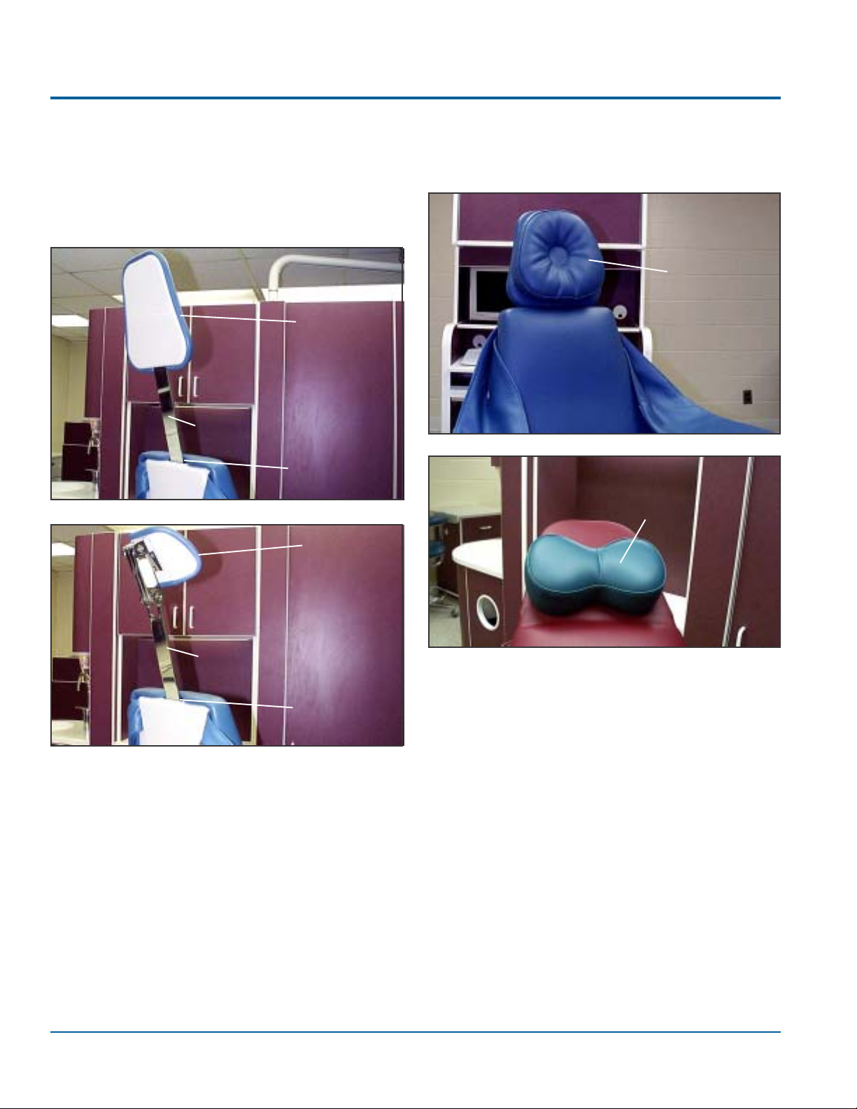
Head Rest
1. Slide the blade of the standard fixed headrest
or the optional double articulating headrest
into the opening of the V-Chair's back
casting.
Standard
Headrest
Blade
Opening
2. Place the magnetic headrest cushion or
magnetic neck support on the J-Chair or the
fixed headrest of the V-Chair.
Magnetic
Headrest
Cushion
Magnetic
Neck
Support
Blade
Optional
Double
Articulating
Headrest
Opening
16 Installation, Operation and Care Manual

Section IV Features
The DentalEZ J/V-Chair can be customized to
attain optimum work efficiency so dental professionals can offer quality care and treatment to patients. In
order to achieve the most efficient use in the operatory
and understand what the J/V-Chair offers, here is a
compilation of some standard and optional features:
Standard
Ergonomic/Comfort Features
The J/V-Chair allows total patient placement
flexibility to create the most comfortable working
position for the patient and dental team. Some of
these ergonomic and comfort features are:
u All chair function controls are conveniently
placed on both sides of the chair back.
u The back, seat and base positions adjust inde-
pendently. This feature allows precise placement
of the patient; therefore, eye, back and neck
strain are virtually eliminated, even after long
procedures.
u The ergonomically designed magnetic headrest
can be placed in any position on the upper
portion of the chair back to comfortably support the patient's head and neck.
Design Features
u Self diagnostics is possible via a series of visual
display signals (LED codes) and audible signals
(beep codes) making each function and control
condition easy to track. (See User Service Section.)
u Any control can be programmed to offer eight
pre-set positions for one operator, or four
presets each for two operators. (See Operation
Section.)
u Every J/V-Chair can accommodate an
additional control. (See Installation Section.)
u The chair can swivel 15° to either side of its
center position.
u Hydraulic, cantilever-style base provides superior
stability and smooth operation.
u The virtually silent hydraulic pump eliminates
distraction.
u Chair-mounted and Magellan-style delivery units
can be mounted.
u Upholstery is removable and replaceable.
Safety Features
u A base lowering safety features ensures nothing
gets caught underneath the base as it lowers. (See
Operation Section.)
u The chair arm and slings recline with patient and
hold the patient's arms in proper position for
better operator access.
u The reshaped, thin, tapered chair back allows
optimum access to the oral cavity while providing more lumbar and cervical support for
increased patient comfort.
u The new chair contour helps remove any ob-
structions from the operator's thighs and knees
allowing for a more ergonomically correct position.
u The seat has stretcher springs for comfort and
durability.
u TheV-Chair's headrest choice of the magnetic
catcher's mitt style cushion, magnetic neck
support or optional double articulating, provides
headrest options to accommodate all dental
procedures.
u A locking chair brake holds the chair in place
and stops any swivel movement. (See Operation
Section.)
u The handpiece operated chair movement lock-
out prevents any unexpected chair movement
while operating any handpiece.
Optional
u Air glide feature allows free and easy floor
positioning of the chair.
u An AC light receptacle outlet can be added to
the chair's AC power.
u Lights can be operated using the auxiliary light
relay button on the touch pad control.
u The V-Chair's headrest options can be easily and
quickly changed.
J-Chair/V-Chair
17

Section V Operation
J-Chair
®
/V-Chair™
Manual Positioning
Manual positioning of the J/V-Chair is accomplished
by using the back switch controls located on each side
of the chair, the foot control or the unit touch pad
control. The J/V-Chair can be operated using one or
two separate controls. To operate these controls:
1. Select the direction of travel.
2. Depress and hold the corresponding button.
3. The chair will move to a factory-set travel
limit, or run until the directional button is
released.
Automatic Positioning
Programming Auto Positions
The J/V-Chair back switch controls, the foot control
and unit touch pad control are capable of executing
eight auto positions (four on A mode indicated by a
green LED and four on B indicated by a yellow
LED).
To establish the pre-sets, refer to the appropriate J/V-
Chair switch control illustration on the next page and
perform the following steps:
1. Determine A or B user by depressing the A/B
toggle button. The A (green) or B (yellow)
LED will light and one beep will sound for A
mode and two beeps will sound for B mode.
2. Situate the chair in the desired auto position.
3. Press and hold the desired auto button (1, 2, 3
or 4) for approximately five seconds.
NOTE: The chair will beep once when the auto button
is first depressed and beep again after the program is
accepted.
4. Repeat Steps 1-3 to program the other three
positions.
18 Installation, Operation and Care Manual

Section V Operation
J-Chair Back Switch Control
Side of Chair
Back Up
Back Down
Seat Up
Seat Down
Base Up
Base Down
LED Light
(A green, one beep)
(B yellow, two beeps)
2
3
4
A
Auxiliary Light
1
B
Operator A/B
Toggle Button
Relay
Auto Buttons
Foot Control
V-Chair Back Switch Control
Side of Chair
1
Back Up
Back Down
Seat Up
2
3
Seat Down
4
Base Up
Base Down
A
B
Unit Touch Pad Control
Auxiliary Light
Relay
Auto Buttons
LED Light
(A green, one
beep)
(B yellow, two
beeps)
Operator A/B
Toggle Button
Operator A/B
Seat Up
Light
Relay
Seat Down
Operator A/B
LED
Auto Buttons
Back Down
Base Up
Back Up
Base
Down
Back Up
Back
Down
Base
Down
A/B
Toggle
Button
A LED
Light
(one beep;
green)
Seat Up
Seat
Down
Base Up
Auxiliary
Light
Relay
B LED
Light
(two beeps;
yellow)
Auto Buttons
J-Chair/V-Chair
19

Section V Operation
J-Chair
®
/V-Chair™
Activating Auto Positions
To activate the auto positions:
1. Determine A or B user by depressing the A/B
toggle button. The A (green) or B (yellow) LED
will light and one beep will sound for A mode
and two beeps will sound for B mode.
2. Depress the #1, 2, 3 or 4 button once on the
back switch control, foot control or the unit
touch pad control.
3. A beep will sound.
4. The chair will automatically stop in the
programmed position selected.
NOTE: Pressing any button on a chair control module
while the J/V-Chair is moving to a programmed
position will immediately stop the movement of the
chair, and three short beeps will sound. To continue and
complete the automatic positioning of the chair, simply
press the desired position button a second time.
Reprogramming Auto Positions
Command Time-out
When a function is moved or an auto position is
activated, the chair assumes movement completion
will take no longer than 45 seconds.
If a function button has been held down or an auto
position has not completed in this allotted time, the
chair will reset itself and restart as though it were
being powered up.
If a button is stuck on a controller, it will fail the
calibration test when the chair restarts and the original
command will be ignored.
If an auto position was activated and for some reason
could not be completed, the chair will not continue trying completion of this command when the chair restarts.
Silent Mode
Anytime a function position button is pressed, a short
beep sounds letting the operator know a function
move has started. These short beeps can be silenced
by changing the #3 DIP switch to the OFF position.
(See Section VII, Dip Switch Settings for details.)
To change a programmed position, simply maneuver
the J/V-Chair to the desired position and follow the
Programming Auto Positions instructions described
earlier in this Section.
NOTE: Reprogramming a new auto position spontane-
ously erases the old position.
Controller Functions/Modes
Controller Self-Calibration
When power is first connected to the chair, each
attached controller having its associated DIP switch
set to the ON position is tested and calibrated.
If a controller does not pass the calibration test, its
commands are ignored and an associated LED code
is generated letting the user know the controller failed
the calibration test.
While the chair is idle, approximately every 15 minutes, the attached controllers are tested and calibrated
to ensure they are working as expected.
Potentiometer Override Mode
In the event one of the three potentiometers used to
measure each function's position on the chair cannot
be read, the chair will automatically switch to a manualonly mode. In this mode, the chair can only be
manually positioned, and the affected function's travel
limits will be its limit switch position or physical limit.
A constant fast beep will sound while an affected
function is being moved to alert the operator the
function requires service. When the affected function
is idle, no beep signal will sound.
All other functions that are operating normally will
maintain their programmed travel limits without
audible signals.
Auto positions cannot be set or activated in this mode
because at least one of the function's positions
cannot be measured.
If any auto position buttons are pressed, the chair will
sound three short beeps to indicate auto positioning
is not available and the chair is in manual-only mode.
20 Installation, Operation and Care Manual

Section V Operation
Standard Features
Base Lowering Safety
The following describes how this feature operates:
1. When the base cantilever section lowers and
contacts an obstruction, the cover on the
underside of the cantilever section moves up
and activates safety switches.
2. Motion of the base stops immediately and the
chair emits a constant short warning beep.
NOTE: As long as the safety switches are
activated, the base will not lower any further. All
other chair functions, except auto programs, are still
available. If the chair is moving to an auto position
and the base cover moves up activating the safety
switches, auto positioning will stop.
3. Moving the base up and off the obstruction
deactivates the safety switches and silences the
warning beep.
Chair Arms
2. Swivel the chair to the desired position.
3. Lock the chair brake by moving the brake
handle to the right.
Standard Headrest (V-Chair)
Firmly push
down or pull
up the blade
from the
chair back to
change the
headrest
height.
Standard
Headrest
Blade
Optional Features
Double Articulating Headrest (V-Chair)
To position the double articulating headrest:
1. While facing the back of the headrest, fully
depress the release mechanism on the left.
The J/V-Chair's floating arm lifts to allow easy
patient entry and exit.
— CAUTION —
The chair's arms (floating or driven) SHOULD
NOT be used as a means of support when
entering, exiting or leaning against the chair.
Chair Rotation
The J/V-Chair is capable of swivelling 15° to
either side of its center position. To swivel the chair:
1. Release the
chair brake
located on the
back of the
chair seat
casting by
moving the
brake handle completely to the left.
Chair Brake Handle
(in lock position)
2. Keep the release mechanism depressed and tilt
the headrest until the desired position is reached.
3. Release the mechanism to lock the headrest in
place.
Double
Articulating
Headrest
(Optional)
Release
Mechanism
NOTE: The use of disposable headrest covers is
recommended to prevent soiling of the headrest. These
covers may be purchased through a local dental supplier.
J-Chair/V-Chair
21

Section V Operation
J-Chair
®
/V-Chair™
Air Glide
The air glide option aids the operator in repositioning
the chair. To operate the air glide option:
1. Make sure the chair is on a smooth hard, level
and non-obstructive surface.
2. Activate the air regulator toggle switch on the
base cover at the rear section of the chair.
Air Regulator
Toggle Switch
Surgical Sling
Make sure the surgical sling board is properly seated
in the pouch located on the underside of the surgical
sling. Then using the two vinyl straps with Velcro,
wrap the patients arm securely in place on the driven
arm of the chair.
Vinyl
Straps
with
Velcro
Surgical
Sling
Board
Driven Arm
3. The rear of the chair base is supported by an
air pillow and lifts off the floor.
4. When the base rear is raised, it allows the
rollers on the front of the base plate to
contact the floor.
5. While the chair is supported only by the rollers
and air pillow, reposition the chair as desired.
Auxiliary Light Relay
The auxiliary light relay allows the operator to turn on
an attached light and then control its on/off state
using the touch pad control. To operate the auxiliary
light relay option:
1. Depress the auxiliary light relay button once
on the touch pad control.
2. One short beep will sound to alert the
operator the light state has changed.
Light Receptacle
(See Installation Section, Page 10.)
3. Pressing the auxiliary light relay button
toggles the on/off state of the light.
22 Installation, Operation and Care Manual

Section VI Care
Cleaning
Before attempting to clean or disinfect the J/V-Chair,
please read the following instructions carefully.
— IMPORTANT —
Pay strict attention to all the cleaning product
manufacturer's warnings and cautions.
Because any cleaning product may be harmful or
irritating:
4 Use protective gloves and eye protection in a
well ventilated area.
4 Do not inhale or swallow any cleaning product.
4 Protect surrounding surfaces and clothing from
exposure.
When using strong cleaning agents, such as bleach or
alcohol, it is advisable to first test them in an inconspicuous area to be certain they will not damage the
upholstery, plastic or metal surfaces of the J/V-Chair.
c. Using a soft cloth dampened in plain
water, wipe away any residue.
2. To remove heavy soil:
a. Dampen a soft, white cloth with lighter
fluid (naphtha) and rub the area gently.
b. Using a soft cloth dampened in plain
water, wipe the area thoroughly.
3. To remove stains using bleach:
a. Prepare a solution comprised of one part
household bleach (sodium hypochlorite)
and nine parts water.
b. Apply the above solution to the stain
using a dampened, soft, white cloth.
NOTE: If necessary, full-strength household
bleach may be applied to the stained area using
a soft, white cloth.
c. Allow the bleach to puddle on the
affected area, or apply a bleach-soaked
cloth to the area for 30 minutes.
— CAUTION —
Cleaning agents, other than household bleach
or rubbing alcohol, may contain harsh or
unknown solvents. Also, these other cleaning
agents are subject to formula changes made
by the manufacturer without notice.
Chair Upholstery
1. To remove light soil:
a. Prepare a solution comprised of one part
household dishwashing liquid and nine
parts warm water.
b. Apply the above solution to the
upholstery using a soft, damp cloth.
NOTE: If necessary, a soft bristle brush
may be used.
d. Using a soft cloth dampened in plain
water, rinse the treated area thoroughly to
remove any bleach residue.
4. To remove stains using alcohol:
a. Dampen a soft, white cloth with rubbing
alcohol and rub the stain gently.
b. Using a soft cloth dampened in plain
water, rinse the treated area thoroughly to
remove any alcohol residue.
5. To restore luster:
a. Apply a light coat of spray furniture wax
containing lemon.
b. Wait 30 seconds and lightly buff the
surface using a clean, white cloth.
J-Chair/V-Chair
23

Section VI Care
J-Chair
®
/V-Chair™
Plastic and Coated Metal Surfaces
— CAUTION —
NEVER use abrasives or petroleum-based
cleaners on any plastic or coated metal surfaces
unless otherwise specified.
1. To remove ordinary dirt:
a. Prepare a soapy solution comprised of
household dishwashing liquid and water.
b. Using a soft cloth or sponge, apply this
soapy solution to the plastic and coated
metal surfaces.
NOTE: To remove heavier dirt, apply Formula
409® or Fantastik®.
c. Wipe the area dry immediately using a soft
cloth.
Bacterial Species:
w Bacillus Subtilis
w Staphylococcus Aureus
w Aerobacter Aerogenes
w Proteus Vulgaris
w Brevibacterium Species
w Streptomyces Rubrireticuli
w Escherichia Coli
w Klebsiella Pneumoniae
w Pseudomonas Aeruginosa
Fungal Species:
w Aspergillus Niger
w Aspergillus Flavus
w Penicillium Funiculosum
w Pennicillium Islandicum
w Chaetonium Globosum
w Trichoderma Species
w Auerobacidium Pullulene
w Canadida Albicans
Upholstery
2. To remove stubborn stains:
a. Apply a mild abrasive such as toothpaste or
liquid tooth polish using a soft, white cloth.
b. Using a chamois or moist sponge, remove
all traces of the mild abrasive.
c. Dry the area thoroughly to prevent marking.
Metal Surfaces and Chrome Parts
For ordinary dirt, fingerprints, etc., use a non-abrasive,
all-purpose cleaner.
Disinfecting
The J/V-Chair's upholstery is comprised of a sulfide
stain, oil and mildew resistant material which provides
outstanding protection in difficult medical and health
care environments. This material contains antimicrobial agents that are effective against the following
microorganisms:
High-Level Disinfection
The J/V-Chair's upholstery material is formulated to
withstand high-level disinfection, which is required in
medical/dental applications. Disinfectant products
that contain sodium hypochlorite (household bleach)
can be used full strength or with gluteraldehydes.
Intermediate-Level Disinfection
This level of disinfection is achieved by applying
either rubbing alcohol or a solution comprised of one
part sodium hypochlorite (household bleach) and nine
parts water. Because sodium hypochlorite is easier to
apply, its use is preferred over rubbing alcohol. To
achieve intermediate-level disinfection, rubbing
alcohol must remain puddled on the upholstery's
surface until evaporation is complete.
All Other Chair Surfaces
Cavicide is recommended for disinfecting all other
surfaces of the J/V-Chair. The use of any disinfectant,
other than Cavicide, may cause premature staining,
discoloration or damage to the J/V-Chair's materials.
24 Installation, Operation and Care Manual
Section VII User Service Information
DIP Switch Settings
A DIP switch assembly, which is located at the top
center of the main control board under the base
cover, is used to set certain functions of the chair's
electronic control package.
— IMPORTANT —
Change DIP switches only while the chair
power is disconnected. Once the chair power is
reconnected, the main control board will
recognize any changes made.
NOTE: The main control board expects at least one
controller attached to the M (main) wiring connector. If
there is no controller attached to either the M or A (auxiliary) connectors, the board will generate a service LED code
that indicates one of the controllers needs checking.
hctiwSPIDetatSnoitcnuF
NO
1#
2#
3#
4#
5#
6#
○○○○○○○○○○○○○○○○○○○○○○○○○○○○○○○○○○○○○○○○○○○○○○○○○○○○○○○○○
FFO
NO
○○○○○○○○○○○○○○○○○○○○○○○○○○○○○○○○○○○○○○○○○○○○○○○○○○○○○○○○○
FFO
NO
○○○○○○○○○○○○○○○○○○○○○○○○○○○○○○○○○○○○○○○○○○○○○○○○○○○○○○○○○
FFO
NO
○○○○○○○○○○○○○○○○○○○○○○○○○○○○○○○○○○○○○○○○○○○○○○○○○○○○○○○○○
FFO
NO
○○○○○○○○○○○○○○○○○○○○○○○○○○○○○○○○○○○○○○○○○○○○○○○○○○○○○○○○○
FFO
NO
○○○○○○○○○○○○○○○○○○○○○○○○○○○○○○○○○○○○○○○○○○○○○○○○○○○○○○○○○
FFO
rellortnoC M si NO .detcennocsirellortnochctiwskcabsemussadraobehtdna
rellortnoC A si NO .detcennocsirellortnoclanoitponasemussadraobehtdna
rellortnoC A si FFO .detcennocsirellortnoconsemussadraobehtdna
.edomnoitarepolamroN
tsuM nieb FFO noitisop
Main Control Board
#1 DIP
Switch
DIP
Switch
Assembly
).detcennocsirewopnehwsesiryllacitamotuaesab(edomnoitallatsnilaicepS
.detavitcaeraspeeblangisnoitavitcadnammocnoitcnuF
.decneliseraspeeblangisnoitavitcadnammocnoitcnuF
.edomgnimmargorpstimillevarT
.snoitcnuftaesdnakcab,esab:edomriahcnoitcnuf-eerhT
.snoitcnuftaes/kcabdnaesab:edomriahcnoitcnuf-owT
Beep Codes
The J/V-Chair's electronic control package is
designed to sound specific beep code signals to alert
the operator of certain control conditions. Understanding the beep codes enables the operator to
isolate the condition and take appropriate action.
Base conditions are indicated by a constant short
beep; back conditions by two constant short beeps;
and seat conditions by three constant short beeps.
Three short beeps indicate a function is not available
when its button is pressed. A constant fast beep that
sounds only when a function is moved indicates a
potentiometer condition.
The beep code signal chart on the following page lists
the audible sound, control condition and service
action to take. The codes are also prioritized letting
the user know that conditions listed above the indicated code are normal.
J-Chair/V-Chair
25

Section VII User Service Information
edoCpeeBnoitidnoCnoitcA
J-Chair
®
/V-Chair™
tnatsnoC
peebtsaf )BF(
tnatsnoC
(peebtrohs )BS
tnatsnoC )BS()BS( detavitca)4SL(hctiwstimilreppukcaB
tnatsnoC
)BS()BS()BS(
tnatsnoC )BS( eriw)7SL(hctiwstimilyrailixuA
)BS()BS()BS(
lortnocynanehW
desserpsinottub
)yaler
esab(edomnoitallatsnilaicepS
)sesiryllacitamotua
NO .rewopriahcehttcennoceR.
dnadetcatnocrevocytefasrewolesaB
&2SL(sehctiwsgnitavitcapudevom
.revoc
)3SL
○○○○○○○○○○○○○○○○○○○○○○○○○○○○○○○○
○○○○○○○○○○○○○○○○○○○○
demmajsirevoC
.ylreporpgnikrows'tierusekamotpu
○○○○○○○○○○○○○○○○○○○○○○○○○○○○○○○○○○○○○○○○○○○○○○○○○○○○
)1SL(hctiwstimilreppuesaB
.stimillevarts'riahcehtmargorpeR
reppustidedeecxeesab(detavitca
)timillevart
.stimillevarts'riahcehtmargorpeR
)timillevartreppustidedeecxekcab(
detavitca)5SL(hctiwstimilrepputaeS
.stimillevarts'riahcehtmargorpeR
)timillevartreppustidedeecxetaes(
○○○○○○○○○○○○○○○○○○○○○○○○○○○○○○○○○○○○○○○○○○○○○○○○○○○○
detavitca)6SL(hctiwstimilrewoltaeS
)timillevartrewolstidedeecxetaes(
.stimillevarts'riahcehtmargorpeR
deggulpnusrotcennoc
○○○○○○○○○○○○○○○○○○○○○○○○○○○○○○○○○○○○○○○○○○○○○○○○○○○○
resu(detavitcahctiwstimilyrailixuA
)noitpodellatsni
srotcennoceriwytefaseceipdnaH
deggulpnu
○○○○○○○○○○○○○○○○○○○○○○○○○○○○○○○○○○○○○○○○○○○○○○○○○○○○
thgilyrailixuatpecxe(
eceipdnaHdetavitcahctiwsytefas
)noitpodellatsni-resu(
ehT.detavitcan .hctiwsetavitcaedyletairporppa
othctiwsPID1#evoM.rewopriahcehttcennocsiD
rednunoitcurtsboevomerdnapuesabehtevoM
revocehthsupnehteerfs'tilitnudnuorarevocevoM
.ylerucesnideggulperasrotcennocerusekaM
tiyhwdnadellatsnisihctiwsehterehwenimreteD
.hctiwsetavitcaedyletairporppanehT.detavitcasaw
.ylerucesnideggulperasrotcennocerusekaM
sihctiwsyhwdnadellatsnisihctiwserehwenimreteD
otualortnocynanehW
margorpnoitisopotuAsidetavitcaton
desserpsinottub
stimillevartnielihW
edomgnimmargorp
si4#hctiwsPID( NO )
2ro1otuarehtiedna
)desserpsinottub
tnatsnoC )BF(
sinoitcnufaelihwylnO
gnivom
egnarfo
26 Installation, Operation and Care Manual
otuaehttuognikcolsiretemoitnetophcihwenimreteD
sretemoitnetoperomroenoesuaceb
egnarfotuorodetcennocsidera
ybrosedocDELecivresehtgnikcehcybsmargorp
delangissi)BF(tnatsnocalitnunoitcnufhcaegnivom
detacidniehtkcehC.noitomnisinoitcnufehtelihw
.noitcnufreporprofegaknildnagniriws'retemoitnetop
.egatlovdnaecnatsiserretemoitnetopehtkcehcnehT
esuacebstimillevartmargorptonnaC
erasretemoitnetoperomroeno
egnarfotuorodetcennocsid
ehttuognikcolsiretemoitnetophcihwenimreteD
DELecivresehtgnikcehcybmargorpstimillevart
)BF(tnatsnocalitnunoitcnufhcaegnivomybrosedoc
ehtkcehC.noitomnisinoitcnufehtelihwdelangissi
rofegaknildnagniriws'retemoitnetopdetacidni
s'retemoitnetopehtkcehcnehT.noitcnufreporp
.egatlovdnaecnatsiser
detavitcaehtnoretemoitnetopehT
tuorodetcennocsidsinoitcnufgnivom
ehtgnikcehcybretemoitnetopdetcepsusehtyfireV
gniriws'retemoitnetopehtkcehC.sedocDELecivres
ehtkcehcnehT.noitcnufreporprofegaknildna
.egatlovdnaecnatsisers'retemoitnetop

Section VII User Service Information
LED Codes
There is a three-light LED assembly on the main
control board that indicates each power up mode and
various service conditions the chair may encounter.
The LED assembly is located at the top center of the
main control board (left of the DIP switch assembly)
under the base cover.
The power-up codes are described in the table below.
A service condition LED code chart appears on the
next page. The LED codes are prioritized from top to
bottom letting the user know the conditions listed
above the indicated code are normal.
LEGEND
LED states: l = On m = Off k = Blinking
edoCDELedoCpeeBhctiwSPIDedoM
mm l
m l m
l mm
PC Board
lll
lll
mmm
lll
lll
lll
lll
lll
mmm
kkk
)BS(
)BS(
)BS(
)BS(
)BS(
)BS(
)BS(
)BF(tnatsnocffO1#)sesiryllacitamotuaesab(noitallatsnilaicepS
ffO4#,nO1#gnitarepolamroN
nO4#,nO1#gnimmargorpstimillevarT
#1 LED
LED
Assembly
Main Control Board
DIP Switch
Assembly
(The LED nearest the main
control board is number one.)
Service Instruction
If the area of concern is not addressed in this
manual, contact your local DentalEZ full-service
dealership. Please have the following product information available:
Model Name
Model Number
(found on the front of the seat mount casting )
Serial Number
Date of Installation
Model/Serial
Number Plate
Seat Mount
Casting
J-Chair/V-Chair
27

Section VII User Service Information
edoCDELnoitidnoCnoitcA
edomnoitallatsnilaicepS othctiwsPID1#evoM.rewopriahcehttcennocsiD nO .
eruliafretrevnocD/A .draoblortnocniamriahcehtecalpeR
deggulpnusrotcennoceriwytefaseceipdnaH
-resu(detavitcahctiwsytefaseceipdnaH
dnadetcatnocrevocytefasrewolesaB
)3SL&2SL(sehctiwsgnitavitcapudevom
mm k
m k m
m kk
kkk
eruliafMORPEE .draoblortnocniamriahcehtecalpeR
)noitpodellatsni
J-Chair
.rewopriahcehttcennoceR
®
/V-Chair™
.ylerucesnideggulperasrotcennocerusekaM
.hctiwsehtetavitcaedyletairporppanehT.detavitca
sawtiyhwdnadellatsnisihctiwsehterehwenimreteD
.revocehtrednunoitcutsboevomerdnapuesabevoM
l mm
ll m
l m l
m l m
mm l
m ll
lll
k mm
k m k
mm l
m ll
lll
mmm
demmajsirevoC
revocehthsupneht,eerfs'tilitnudnuorarevocehtevoM
.ylreporpgnikrows'tierusekamotpu
detavitca)1SL(hctiwstimilreppuesaB
.stimillevarts'riahcehtmargorpeR
)stimillevartreppus'tidedeecxeesab(
detavitca)4SL(hctiwstimilreppukcaB
.stimillevarts'riahcehtmargorpeR
)timillevartreppustidedeecxekcab(
taes(detavitca)5SL(hctiwstimilrepputaeS
.stimillevarts'riahcehtmargorpeR
timillevartreppustidedeecxe
taes(detavitca)6SL(hctiwstimilrewoltaeS
.stimillevarts'riahcehtmargorpeR
timillevartrewolstidedeecxe
srotcennoceriw)7SL(hctiwstimilyrailixuA
.ylerucesnideggulperasrotcennocerusekaM
deggulpnu
dellatsni-resu(detavitcahctiwstimilyrailixuA
)noitpo
rodetcennocsidsi)1P(retemoitnetopesaB
gnivomsiesabelihwylnO
egnarfotuo
rodetcennocsidsi)2P(retemoitnetopkcaB
gnivomsikcabelihwylnO
egnarfotuo
rodetcennocsidsi)3P(retemoitnetoptaeS
gnivomsitaeselihwylnO
egnarfotuo
.noitcnufreporp.egatlovdnaecnatsiserstikcehcnehT
sawtiyhwdnadellatsnisihctiwsehterehwenimreteD
.hctiwsehtetavitcaedyletairporppanehT.detavitca
rofegaknildnagniriws'retemoitnetopesabehtkcehC
.egatlovdnaecnatsiserstikcehcnehT.noitcnufreporp
rofegaknildnagniriws'retemoitnetopkcabehtkcehC
.egatlovdnaecnatsiserstikcehcnehT.noitcnufreporp
rofegaknildnagniriws'retemoitnetoptaesehtkcehC
rellortnoC M etarbilactonlliw)niam( kcehC.snoitcennocesoolroskaerbrofgniriwkcehC
.sehctiwskcutsrof
○○○○○○○○○○○○○○○○○○○○○○○○○○○○○○
ehtotdetcennocsirellortnocaerusekaM M fI.gniriw
otdetcennocebdluohsti,desusirellortnocenoylno M.
○○○○○○○○○○○○○○○○○○○○○○○○○○○○○○
rellortnocgnicrofrewopriahctcennocerdnatcennocsiD
.etarbilactonlliwllitstifirellortnocecalpeR.snoitarbilac
rellortnoC A etarbilactonlliw)yrailixua( rofkcehC.snoitcennocesoolroskaerbrofgniriwkcehC
.sehctiwskcuts
○○○○○○○○○○○○○○○○○○○○○○○○○○○○○○
otdetcennoctonsirellortnocafI ,A PID2#egnahc
othctiws FFO .etarbilactonlliwtios
○○○○○○○○○○○○○○○○○○○○○○○○○○○○○○
rellortnocgnicrofrewopriahctcennocerdnatcennocsiD
.etarbilactonlliwllitstifirellortnocecalpeR.snoitarbilac
eldisiriahcnehW
egnarfotuo
rodetcennocsidsi)2P(retemoitnetopkcaB
rodetcennocsidsi)1P(retemoitnetopesaB
eldisiriahcnehW
egnarfotuo
rodetcennocsidsi)3P(retemoitnetoptaeS
eldisiriahcnehW
egnarfotuo
rofegaknildnagniriws'retemoitnetopesabehtkcehC
.egatlovdnaecnatsiserstikcehcnehT.noticnufreporp
rofegaknildnagniriws'retemoitnetopkcabehtkcehC
.egatlovdnaecnatsiserstikcehcnehT.noitcnufreporp
rofegaknildnagniriws'retemoitnetoptaesehtkcehC
.egatlovdnaecnatsiserstikcehcnehT.noitcnufreporp
lamroN
28 Installation, Operation and Care Manual

Section VII User Service Information
Programming Travel Limits
Tools Required:
Phillips Screwdriver
Tape Measure
— WARNING —
Disconnect the chair power when indicated.
1. Raise the chair base and seat to their full UP
position, and place the chair back in a halfway
position.
2. Disconnect the chair power.
3. If the upholstered seat was installed, take it
off by unsnapping the decorator plastic cover
caps on the back and front of the chair seat
mount casting and removing and retaining the
1/4-20 x 5/8" screws with plastic caps from
the back and front of the chair seat cushion.
4. Take off the base (pump) cover by removing
and retaining the four Phillips-head screws
that attach it to the base plate.
NOTE:
specified are factory settings. Values within the ranges
are valid depending on specific applications. Different
travel limit values may be required to achieve adequate
clearance for accessories attached to or near the chair.
The upper and lower travel limit values
NOTE: Any one of the two possible controls con-
nected to the chair can be used to set the travel limits.
7. Perform the following steps to program the
upper limits:
a. Move the base up until the distance
between the bottom of the chair
mount casting and the top of the
cantilever support casting measures
between 22-5/8" and 22-3/4".
b. Move the back up until the distance between
the end of the spring connecting link and
the rear edge of the seat mount casting rib
measures between 14" and 14-1/8".
c. Move the seat up until the distance
between the chair mount casting and the
top edge of the seat mount casting
measures between 10-1/2" and 10-5/8".
5. On the main control board, flip the #4 DIP
switch to the ON position. (This will place the
chair in its travel limits programming mode
when the chairs power is reconnected.)
#4 DIP Switch
Main Control
Board
NOTE: All three LEDs on the board will light up
five times, along with a short beep each time, to indicate
the chair is in its travel limits programming mode.
6. Reconnect the chair power.
Step 7a
Cantilever
Support
Casting
Step 7b
Step 7c
Chair
Mount
Casting
Seat Mount Casting Rib
Spring Connecting Link
Chair
Mount
Casting
Seat
Mount
J-Chair/V-Chair
29

Section VII User Service Information
J-Chair
®
/V-Chair™
d. Press and release the auto #1 button on a
control.
— CAUTION —
Do not press the auto button for more
than one second.
NOTE: A short beep will sound when the button is
pressed, another will sound when the button is released.
The second beep indicates the travel limits have been
stored.
8. Perform the following steps to program the
lower limits:
a. Move the base down until the distance
between the bottom of the chair mount
casting and the top of the cantilever
support casting measures between 9-1/4"
and 9-3/8".
Step 8a
Step 8c
b. Move the back down until the distance
between the end of the spring connecting
link and the rear edge of the seat mount
casting rib measures between 11" and
11-1/8".
c. Move the seat down until the distance
between the chair mount casting and the
top edge of the seat mount casting
measures between 6-1/2" and 6-5/8".
d. Press and release the auto #2 button on a
control.
— CAUTION —
Do not press the auto button for more
than one second.
NOTE: A short beep will sound when the button is
pressed, another will sound when the button is released.
The second beep indicates the travel limits have been
stored.
Chair
Mount
Casting
Step 8b
Cantilever
Support
Casting
Seat Mount Casting Rib
Spring Connecting Link
Seat
Mount
Chair
Mount
Casting
9. Disconnect the chair power.
10. Flip the #4 DIP switch back to the OFF
position. (This will place the chair back into
its normal operating mode.)
11. Reconnect the chair power.
12. Move each function to their programmed
limits to verify they have been properly set.
(Each function should stop before activating a
limit switch or reaching a physical stop.)
NOTE: If a limit was adjusted to accommo-
date an accessory, make sure the resulting
clearance is sufficient.
13. Replace the pump cover using the four
Phillips-head screws previously removed.
14. Replace the seat using the four 1/4-20 x 5/8"
screws with plastic caps previously removed.
15. Reprogram the auto positions.
30 Installation, Operation and Care Manual

Section VII User Service Information
Control Valve Speed Adjustment
Tools Required:
Phillips Screwdriver
Flat-head Screwdriver
Safety Glasses
1. Raise the chair base to its full UP position.
2. Take off the base (pump) cover by removing
and retaining the four Phillips-head screws
that attach it to the base plate.
NOTE: Adjustable flow control valves, located in the
hydraulic control valve, are used to set the chair function
speeds. The base and back cylinders are single acting
cylinders. They have two flow control valves each (UP
and DOWN) to control their speeds. The seat cylinder
is double acting and requires four flow adjustment
valves. Valves marked (PWR) are for incoming
fluid. Valves marked (RET) are for outgoing
fluid. The (RET) valves are adjusted first to set a
gross speed and the (PWR) valves are used for fine
tuning the speeds. Once the (RET) flows have been set,
they should not be readjusted.
Function times given are based on a 200-pound person
sitting in the chair.
— WARNING —
Wear safety glasses while adjusting the valve.
Flow control valves should not be turned out
farther than the top of their heads being even
with the valve body surface. Adjustment of
the flow control valves beyond the valve body
surface may result in oil leakage with uncontrolled motion of the chair and the possibility
of a valve being ejected from the valve body.
a. Move the base up and down adjusting the
flow controls until it takes 12 seconds for
the base to move either up or down the
full travel.
b. Move the back up and down adjusting the
flow controls until it takes 12 seconds for
the back to move either up or down the
full travel.
UP
(RET)
DOWN
(RET)
DOWN
(PWR)
UP
(PWR)
CV4
DentalEZ Group
2500 Highway 31 South
Bay Minette, AL 36507
Hydraulic Valve
FLOW
INC.
DOWN
DOWN
SEAT
DEC.
UP
BACK
UP
BASE
CV3
CV2
CV1
J-Chair/V-Chair
31

Section VII User Service Information
c. Adjust the UP (PWR) and DOWN (PWR)
flow adjustment screws all the way open
(counterclockwise). The valves are open
when the top of the screws are
approximately level with the valve body.
d. Adjust the UP (RET) and DOWN (RET)
flow adjustments all the way closed
(clockwise).
NOTE: With the flow adjustments closed all the way,
the seat may not move at all until the valve is adjusted
open a little.
e. Move the seat up or down while opening
the corresponding (RET) flow
adjustments.
f. Continue adjusting the flows until the seat
moves from its full up and down positions
in about seven seconds both ways.
J-Chair
®
/V-Chair™
g. Adjust the UP (PWR) and DOWN (PWR)
flow adjustment screws all the way closed
(clockwise).
h. Move the seat up or down while opening
the corresponding (PWR) flow
adjustments.
i. Continue adjusting the flows until the seat
moves from its full up and down positions
in about nine seconds both ways.
3. Raise the chair base up.
4. Replace the base (pump) cover.
32 Installation, Operation and Care Manual

Section VIII Parts List
J-Chair (J-3) Upholstery
emaNtiK/traP.oNtiK/traP
(,3-J,teSyretslohpU nehwdeificepsroloc
)*/wdekramsmetisedulcnidnariahcgniredro
rotroppuSkceN*tserdaeH
ttiMs'rehctaC
*noihsuCkcaB678-1083
gnilSmrA *)tikrepowt( 347-1083
*"51,noihsuCtsermrAtfeL447-1083
*"51,noihsuCtsermrAthgiR647-1083
*)tsermra"51(etalPrevoCmrAnevirD839-1083
)tsermra"61(etalPrevoCmrAnevirD947-1083
*)tsermra"51(etalPrevoCmrAgnitaolF939-1083
)tsermra"61(etalPrevoCmrAgnitaolF057-1083
*noihsuCtaeS157-1083
*erawdraHgnitnuoMtaeS257-1083
*drauGeoTtaeS357-1083
*revoCrewoLtaeS457-1083
srenetsaFpirGdnilBkcaB247-1083
V-Chair Upholstery
emaNtiK/traP.oNtiK/traP
(,riahC-V,teSyretslohpU nehwdeificepsroloc
)*/wdekramsmetisedulcnidnariahcgniredro
*noihsuCkcaB219-1083
gnilSmrA *)tikrepowt( 347-1083
*noihsuCtsermrAtfeL447-1083
*noihsuCtsermrAthgiR647-1083
*etalPrevoCmrAnevirD947-1083
*etalPrevoCmrAgnitaolF057-1083
*noihsuCtaeS157-1083
*erawdraHgnitnuoMtaeS257-1083
*drauGeoTtaeS357-1083
*revoCrewoLtaeS457-1083
*noihsuCtserdaeHdradnatS728-1083
*noihsuCcitengaMtserdaeHdradnatS628-1083
).noitpo(*noihsuCtserdaeHgnitalucitrAelbuoD535-1083
sgnilSlacigruS )lanoitpo(*)tikrepowt( 116-5263
srenetsaFpirGdnilBkcaB247-1083
Electrical
emaNtiK/traP.oNtiK/traP
)CAV511(draoBtiucriCretsaM567-1083
)CAV022(draoBtiucriCretsaM887-1083
)CAV511(sesuF667-1083
)CAV022(sesuF767-1083
ssenraHgniriWniaM867-1083
)CAV511(droCrewoP967-1083
)CAV022(droCrewoP077-1083
)CAV511(roticapaCrotoMpmuP904-1083
)CAV022(roticapaCrotoMpmuP014-1083
)CAV511(dioneloSevlaV424-1083
)CAV022(dioneloSevlaV524-1083
retemoitnetoPesaB534-1083
)lla(hctiwStimiL134-1083
retemoitnetoPtaeSdnakcaB177-1083
ssenraHgniriWhctiwSkcaB519-1083
elbaClortnoCkcaB358-1083
noitpOelcatpeceRthgiL594-5263
Controls
emaNtiK/traP.oNtiK/traP
785-5263
047-1083
628-1083
hctiwSkcaBthgiR3-J498-1083
hctiwSkcaBtfeL3-J598-1083
hctiwSkcaBthgiRriahC-V319-1083
hctiwSkcaBtfeLriahC-V419-1083
noitpOdaPhcuoTdaeHyrevileD165-5263
ylbmessAdaPhcuoT957-1083
hctiwSenarbmeMdaPhcuoT067-1083
hctiwSenarbmeMmrAs'tnatsissAraeR097-1083
draoBtiucriCdaPhcuoT167-1083
noitpOlortnoCtooF845-5263
draoBtiucriClortnoCtooFdnakcaB367-1083
droClortnoCtooF467-1083
)CAV511(noitpOyaleRthgiL945-5263
)CAV022(noitpOyaleRthgiL195-5263
)eludomrewoprofCAV42(noitpOyaleRthgiL695-5263
noitpOhctiwSytefaSeceipdnaH265-5263
Mechanical
emaNtiK/traP.oNtiK/traP
wercSmrA211-0083
406-5263
gnirpS544-1083
eveelSlortnoC311-0083
sniPtoviPtaeS277-1083
rotautcAretemoitnetoPtaeSdnakcaB377-1083
retsaCedilGriA086-1083
rotalugeRedilGriA197-1083
hctiwSelggoTedilGriA297-1083
Hydraulic
emaNtiK/traP.oNtiK/traP
)CAV511(pmuP477-1083
)CAV022(pmuP577-1083
)CAV511(evlaV677-1083
)CAV022(evlaV777-1083
riovreseRdiulF877-1083
rednilyCesaB924-1083
rednilyCtaeSdnakcaB387-1083
)evlavotpmup(esoH087-1083
)rednilycesab(esoH487-1083
)putaesdnakcab(esoH187-1083
)nwodtaes(esoH287-1083
gnibuTtneVrednilyCkcaBdnaesaB814-1083
gnibuTriovreseRdnapmuP714-1083
)tnipeno(liOciluardyH945-1083
Exterior Components
emaNtiK/traP.oNtiK/traP
mrAtfeL547-1083
mrAthgiR747-1083
mrAevirD847-1083
revoCekarB557-1083
eldnaHekarB308-1083
revoCesaBpoT787-1083
revoCesaBmottoB657-1083
ylbmessArevoCtnorF397-1083
revoCpmuP737-1083
J-Chair/V-Chair
33

J-Chair®/V-Chair™Product Support Services
DentalEZ Group
DentalEZ Equipment Division
J-Chair (Model J-3) and V-Chair
The DentalEZ Group and its employees are proud of the products we provide in the dental community. We stand behind
these products with a warranty against defects in material and workmanship as provided below and have our own in-house
repair facility to service our products.
In the event you experience difficulty with the application or operation of any of our products, please contact our Customer
Service Department at our expense at 1-866-DTE-INFO (1-866-383-4636).
If we cannot resolve the issue by telephone, we will arrange for a representative to contact you or suggest that the product be
returned to our factory for inspection.
If product repair or return is required, we will provide you with a Return Authorization number and shipping instructions to
return the product to the proper facility. If the product is under warranty, we will ask you to provide proof of purchase, such
as a copy of your invoice. Please be sure to include the Return Authorization number on the package you are returning.
Products returned without a Return Authorization number cannot be repaired.
Freight costs for product returns are the responsibility of the customer. Products under warranty will be repaired or replaced
at our sole discretion and returned at our expense. Products outside the warranty limits will be repaired and returned with
costs invoiced to the customer. We are not responsible for shipping damages. We will, however, help you file a claim with the
freight carrier. Written repair estimates are available.
DentalEZ warrants the J/V-Chair to be free of defects in material and workmanship, under normal usage, under the following terms:
The following items are covered under this limited warranty for a period of three (3) years from the date of installation:*
Structures: Base Plate, Castings, Chair Seat and Back
Hydraulic System: Cylinders, Solenoid Valves and Pump
Electronics: Master Circuit Board and Foot Control Circuit Board, Chair Control
The upholstery package is covered under this limited warranty for a period of one (1) year from the date of installation.
Please note the following additional terms of our warranty and return policy:
Warranties cover manufacturing defects only and do not cover costs resulting from abuse, improper handling, cleaning,
care or maintenance, normal wear and tear or non-observance of operating, maintenance or installation instructions.
Failure to use authorized parts or an authorized repair facility voids this warranty.
Liability is limited to repair or replacement of the defective product at our sole discretion. All other liabilities, in
particular liability for damages, including, without limitation, consequential or incidental damages are excluded.
THIS WARRANTY IS IN LIEU OF ALL OTHER WARRANTIES, EXPRESSED OR IMPLIED, INCLUDING
ANY IMPLIED WARRANTIES OF MERCHANTABILITY OR FITNESS FOR A PARTICULAR PURPOSE. NO
EMPLOYEE, REPRESENTATIVE OR DEALER IS AUTHORIZED TO CHANGE THIS WARRANTY IN ANY
WAY OR TO GRANT ANY OTHER WARRANTY.
WARRANTY REPAIRS: Parts repaired or replaced on a product that is in warranty will be warranted for the duration of that
products original warranty.
NON-WARRANTY REPAIRS: The warranty on parts either repaired or replaced on an out-of-warranty product will cover
the repaired part only and will be for the time frame of a new parts warranty period.
PRODUCT RETURN: Opened product returns more than a year old cannot be returned for credit. There will be a 15%
($25.00 minimum) restocking charge on all items authorized for return.
* Provided conditions defined in the Installation, Operation and Care Manual are met.
V-Chair is a trademark, and DentalEZ, aXcs and J-Chair are registered trademarks of DentalEZ, Inc.
© 2002, DentalEZ Alabama, Inc.
34 Installation, Operation and Care Manual
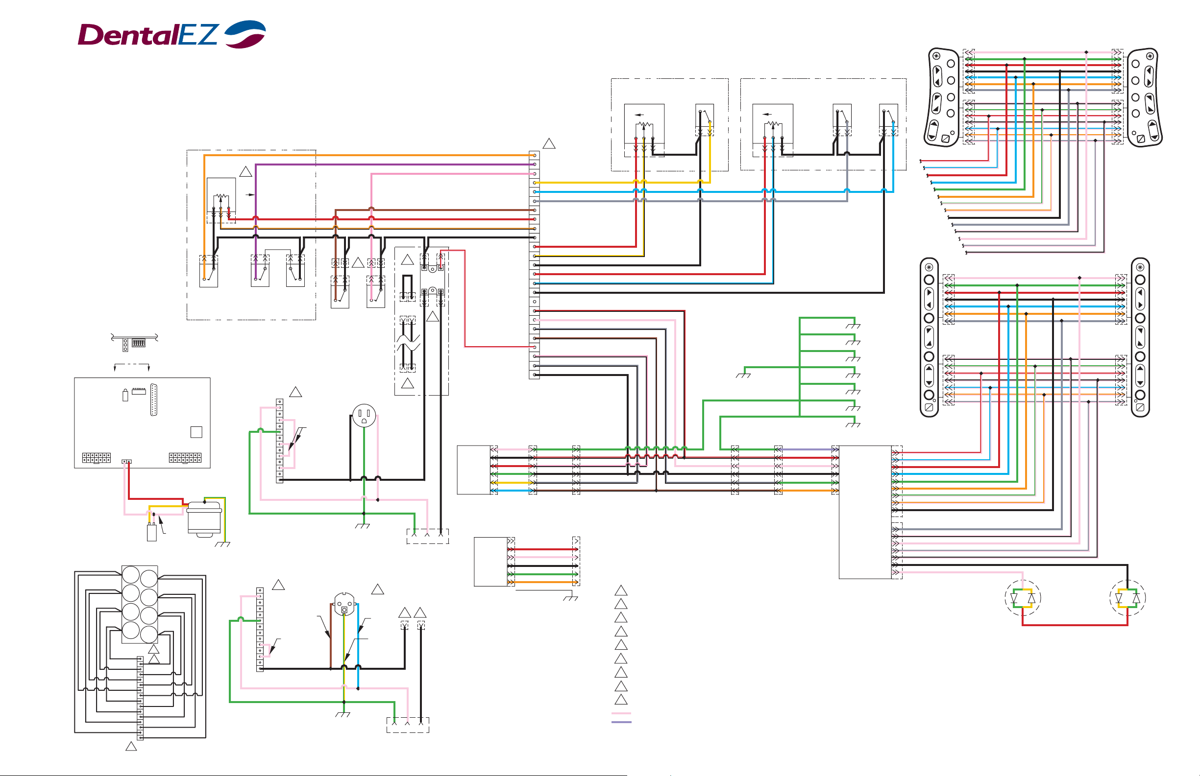
J-Chair /V-Chair
®
Wiring Schematic
Potentiometer
Up
1 2 3
N.C.
Base Upper
Limit Switch
(LS1)
1
2
LED
ASSEMBLY
3
A
MASTER CONTROL BOARD
P3
17 1
814
CAPACITOR
654321
View A-A
654321
P1
White
PWR
SEAT
DOWN
SV7
SEAT
UP
SV6
BACK
UP
SV3
BASE
UP
SV1
16
3
DIP SWITCH
ASSEMBLY
A
1
14
25
13
Red
Yellow
AC
White/Brown
RET
SEAT
UP
SV8
SEAT
DOWN
SV6
BACK
DOWN
SV4
BASE
DOWN
SV2
2
P5
1
1
P4
9
White
or
P2
P5
8
16
Green/Yellow
PUMP
(Ground)
Chassis
™
BASE CANTILEVER
Base
4
(P1)
CW
CW
N.C.
Limit
Switch
(LS2)
LOWER COVER
115 VAC
HOOKUP
1
3
4
5
7
8
9
10
11
12
13
14
220 VAC
HOOKUP
P3
1
2
3
4
5
6
7
8
9
10
11
12
13
14
N.C.
P3
Limit
Switch
(LS3)
1
2
6
White
N.C.
Auxiliary
Limit
Switch
(LS7)
(Optional)
Black (AC Line Hot)
White (AC Line Neutral)
Green (Safety Ground)
Brown
(AC Line
Hot)
220V CHAIR
POWER CORD
1
White
Black
White
Green
Chassis
6
N.C.
Safety
Handpiece
(Optional)
115V CHAIR
POWER CORD
Chassis
9
Blue
(Neutral)
Green
Yellow
(Safety
Ground)
5
AUX AC
RELAY
Black
8
3 2 1
CHAIR LIGHT
CONNECTION
5
7
Black
3 2 1
CHAIR LIGHT
CONNECTION
1
7
1
7
1
7
1
7
V-Chair
LEFT
SWITCH
1
2
3
4
A
B
J-Chair
LEFT
SWITCH
1
2
3
4
A
B
Green
V-Chair
RIGHT
SWITCH
BACK SEAT
Seat Lower
Limit Switch
(LS6)
N.C.
Black
Cantilever Base Pivot
Cantilever
Safety Switches
Chair Mount
Seat Controls
Black
Back Upper
Limit Switch
(LS4)
N.C.
Seat
Potentiometer
(P3)
Up
Green
Back
Potentiometer
(P2)
Up
1
Pink
P4
1
2
3
Yellow
4
Blue
5
Gray
6
7
8
9
10
11
12
13
14
15
16
17
18
19
20
21
23
24
25
Red (+5 VDC)
Yellow/Black
Black (DC Ground)
Red (+5 VDC)
Blue/Black
Black (DC Ground)
Red/Black (+12 VDC)
White (Control Signal M)
Gray/Black (Calibration M)
Brown/Black (Operator A/B LED)
22
White/Black (Control Signal A)
Gray/Black (Calibration A)
Black (DC Ground)
Orange
Purple
Brown
Red (+5 VDC)
Orange/Black
Black (DC Ground)
7
Red/White (Relay)
1 2 3 1 2 3
Chassis
Seat Mount
Back Controls
Drain Wire
Red
White
Black
Green
Orange
1
2
3
4
5
6
Black
TOUCH
PAD
CONROL
A
(Optional)
FOOT
CONROL
(Optional)
Green
White
1
Black
2
Red
3
Green
4
Yellow
5
Blue
6
CHAIR
A WIRING
EXTENSION
Red
White
Black
A
Green
Orange
Shield
Green
1
Red/Black
2
White/Black
3
Black
4
Gray/Black
5
Brown/Black
6
1
2
3
4
5
6
Red/Black
Gray/Black
Brown/Black
White
Black
2
3
4
5
6
CHAIR
M WIRING
EXTENSION
1
Connections shown in line for clarity.
2
All wires are black.
3
Pins 9 through 12 are neutral.
4
As functions move up, all potentiometer pin #2 voltages increase.
5
When a relay is not used, a shielded jumper wire is placed in line on the light connection.
6
When optional switches are not installed, connectors are plugged into each other.
7
120 & 220 VAC relays connect to the chair light connection.
8
24 VAC relay connects to the CMU main wire harness through a jumper wire which controls the light common.
9
International AC connection. Not used in US.
1
Black
J1
BACK
CONTROL
BOARD
Seat Upper
Limit Switch
(LS5)
N.C.
J3
J4
A
Red/White (Base Up)
Blue/White (Base Down)
Red (Back Up)
Blue (Back Down)
Green (Auto #1)
Orange (Auto #2)
Green/White (Auto #3)
Orange/White (Auto #4)
Black (Ground)
J-Chair
RIGHT
SWITCH
1
2
3
4
A
B
Red/White (Base Up)
1
Blue/White (Base Down)
2
Red (Back Up)
3
Blue (Back Down)
4
Green (Auto #1)
5
Orange (Auto #2)
6
Green/White (Auto #3)
7
Orange/White (Auto #4)
8
Black (Ground)
9
1
Gray (Seat Up)
2
White/Black (Seat Down)
3
White (Auxiliary Relay)
4
Gray/White (OP A/B)
5
Black/White (Shield Ground)
6
Black (Yellow LED)
7
White (Green LED)
7
1
2
1
3
7
4
B
1
Gray (Seat Up)
White/Black (Seat Down)
White (Auxiliary Relay)
Gray/White (OP A/B)
Black/White (Shield Ground)
7
1
7
1
Green
Yellow
Yellow
Red
= White
= Clear
P.N. 2717-202B
Schematic

DentalEZ Group
2500 Highway 31 South
Bay Minette, Alabama 36507
Phone: 1-866-DTE-INFO
Fax: (251) 937-0461
www.dentalez.com
PN: 2717-202B
Printed in USA
© DentalEZ Alabama, Inc.
August, 2002
 Loading...