

CORETM Delivery Unit
Magellan Mount
User Manual

Table of Contents
DentalEZ
®
Equipment
Section I Introduction
Product Overview ............................................... 1
Magellan Unit Features ......................................2
Dimensions ........................................................ 3
Speci cations .................................................... 4
Classi cations ................................................... 5
Explanation of Symbols & Signs ...................... 5
Safety Precautions ............................................ 6
Section II Preinstallation
Packaging .......................................................... 9
Unit Placement ................................................. 10
Utility Service Center (USC) ............................. 10
Section III Installation
Magellan Unit Support ..................................... 13
Umbilical Assembly .......................................... 15
Finalizing USC Installation ............................... 17
Magellan Unit Post ............................................ 19
Delivery Head ................................................... 20
USC Base ........................................................... 21
Rear Assistant .................................................. 21
Assistant’s Arm (Optional) .............................. 22
Assistant’s Instrumentation (Optional) ......... 23
Fiber Optic Tubing (Optional).......................... 24
Fiber Optic Electrical (Optional) ..................... 24
Light or Monitor Pole (Optional) ..................... 25
Power Module (Optional)................................. 26
Section VI Care
Cleaning ........................................................... 37
Disinfecting ...................................................... 38
Section VII User Service Information
Troubleshooting .............................................. 39
Service Instruction .......................................... 42
Disposal of Equipment .................................... 42
Section VIII Parts Lists/Diagrams
Utility Service Center ...................................... 43
Pivot/Mounting Hardware ............................... 43
Simplicity Assistant’s Arm (Optional) ............ 44
Galaxy Assistant’s Arm (Optional) ................. 45
CORE Assistant’s Arm (Optional) ................... 46
CORE Delivery Head ........................................ 47
Touch Pads ....................................................... 48
Clean Water System ........................................ 49
Foot Control ..................................................... 49
Air/Water Syringe ............................................ 50
HVE Nozzle ....................................................... 50
Saliva Ejector Nozzle ....................................... 50
EMC Information .............................................. 53
Limited Warranty ............................................. 55
Section IV Testing
Delivery System ............................................... 29
Syringe ............................................................. 30
Foot Control and Handpieces ......................... 30
Other Optional Features.................................. 32
Section V Operation
Delivery Head ................................................... 33
Syringe ............................................................. 34
Foot Control ..................................................... 34
Assistant’s Vacuum Accessories ................... 35
Clean Water System ........................................ 35
www.DentalEZ.com
PN: 2717-267C
866-DTE-INFO
i
i

CORETM Magellan Unit
www.DentalEZ.com
PN: 2717-267C
866-DTE-INFO
ii

Section I Introduction
DentalEZ
®
Equipment
Product Overview
This manual contains installation, operation and
care instructions, and user service information for
the DentalEZ® CORE™ Magellan Dental Delivery
Unit.
The CORE Magellan unit is intended to be used
by trained professional dental care personnel
only as an interface device to connect the dental
operatory hand instruments to the appropriate
supply utility such as air, water, vacuum, drain and
electrical. It functions as a system management
device that provides a method of operating the
hand instruments from a single control input
device.
The CORE Magellan unit is manufactured to be
used with a dental chair that supports a patient
in a reclined seated position. Operators will be
positioned around the patient’s head as required
for optimum access for the speci c procedure
being performed. The delivery unit positions the
handpieces for the optimum presentation to the
operator.
NOTICE
• Installation by an authorized
DentalEZ dealer service technician is
recommended.
• For any questions about an order, please
contact a DentalEZ Equipment customer
service representative at 866-DTE-INFO.
Light Post
(Optional)
Adjustable
Rear Assistant’s
Arm & Mount
(Optional
Delivery
Head
Magellan
Unit Post
Arm
The CORE Magellan unit is designed to provide
trouble-free service when installed, operated and
cared for according to the procedures set forth in
this manual.
To ensure proper installation, carefully
read all of the instructions contained in
this manual, paying close attention to all
warnings, cautions and notes.
Before starting installation procedures, review
the illustration to become familiar with the
components of the CORE Magellan unit (Figure 1).
After the CORE Magellan unit is installed, review
the features, operation procedures, and care
guidelines with the doctor’s sta .
Leave this manual in the doctor’s o ice.
Clean
Water
System
Magellan
Unit
Support
Figure 1. Main components of the CORE Magellan unit
www.DentalEZ.com
PN: 2717-267C
866-DTE-INFO
1
1

Section I Introduction
CORETM Magellan Unit
Magellan Unit Features
Designed with simplicity in mind, the CORE product line provides a straightforward, easy-to-use delivery
unit with common components, simple integrated holders and an easy-to-read pressure gauge. The
left/right Magellan-style mount unit positions StarDental® handpieces and ancillaries within easy,
comfortable reach.
Standard Features
• Secure tray placement.
• Air gauge for easy pressure
monitoring.
• Break release handle.
• Easy access control block and
internals for easy maintenance.
• Aluminum ex arm for stability and
ease of positioning.
• Built standard with BioFreeTM tubing.
Optional Features
• Optional integrated dual access touchpad controls.
• Rear assistant’s arm/instrumentation with centrally located solids collector and tubing.
www.DentalEZ.com
PN: 2717-267C
866-DTE-INFO
2

Section I Introduction
Dimensions
DentalEZ
®
Equipment
24¼"
16"
20¾"
15¼"
23½"
R23"
21¼"
R26¾"
1½"
19"
15¾"
17½"
Figure 2. Top and side view dimensions for the CORE Magellan-mount delivery unit
www.DentalEZ.com
PN: 2717-267C
3
3
57"
41"
10½"
10½-23⅞"
6¼"
866-DTE-INFO

Section I Introduction
CORETM Magellan Unit
Speci cations
Power Supply
• 115V AC, 50/60 Hz, as applicable
Air Pressure
• 551.6 kPa (80 PSI) (at regulator in USC)
Water Pressure
• 275.8 kPa (40 PSI) (at regulator in USC or clean
water manifold)
Clean Water System
• Reservoir capacity: 2.0 L
Shipping (Package) Weight
• CORE Traditional Delivery Head and Arms:
24.5 lb. (11.1 kg)
Recommended Environmental Conditions
Transportation and Storage
• Temperature range: -20°F to 165°F
(-29°C to 74°C)
• Relative humidity range: 0% to 95%
Operation
• Temperature range: 59°F to 80°F (15°C to 27°C)
• Relative humidity range: 0% to 95%
• Atmospheric pressure range: 50 to 105 kPa
• Magellan Delivery Unit Post: 13 lb. (5.8 kg)
• Magellan Delivery Unit Support: 20 lb. (9 kg)
• Utility Service Center (USC): 15 lb. (6.8 kg)
• Assistant’s Arm: 16 lb. (7.2 kg)
• Light Post (Optional): 15 lb. (6.8 kg)
www.DentalEZ.com
PN: 2717-267C
866-DTE-INFO
4

Section I Introduction
DentalEZ
®
Equipment
Classi cations
Medical-General Medical Equipment
Certi ed as to electrical shock, re
E355890
For the purposes of this user manual, the UL
approval is for the unit (head/arm assembly) and
power supply. All other regulatory markings are
provided in their respective manuals.
• Type of Protection Against Electric Shock:
Class 1 Equipment.
• Degree of Protection Against Electric Shock:
Type B Applied Parts. The handpiece is
considered an applied part.
and mechanical hazards only in
53HN
accordance with:
ANSI/AAMI ES60601-1:2005
CAN/CSA C22.2 NO. 60601-1-08
IEC 80601-2-60:2012
Explanation of Symbols & Signs
= Caution
= Warning
= Biohazard
= Warning - Dangerous Voltage
= General Mandatory Action
= Refer to Manual (Follow Instructions)
= Alternating Current
= Direct Current
= Protective Earth (Ground)
= Type B Applied Part
• Degree of Protection Against Ingress of Water:
Ordinary
• Flammable Gases: Equipment not suitable for
use in the presence of a ammable anesthetic
mixture with air, oxygen or nitrous oxide.
• Not intended for use in an oxygen rich
environment.
• Mode of Operation: Continuous
The authorized European representative is:
Dental Hygienics & Decontamination (DHD)
41 Blackwell Drive, Braintree Business Park
Braintree Essex, CM7 2PU, UK
Phone: +44 01787 877877 (ext. 200)
= European Certi cation
= Serial Number
= Manufacture Date
= Manufacturer
= Electromagnetic Radiation
= Do Not Trash
= Box Must Remain Upright
= Do Not Place Box on Unlevel Surface
= Do Not Stack Box
= Box Contents Safe Temperature Range
= Box Contents Safe Humidity Range
www.DentalEZ.com
PN: 2717-267C
866-DTE-INFO
5
5

Section I Introduction
CORETMMagellan Unit
Safety Precautions
WARNING
Before proceeding with electrical
installation, all wiring must be in
accordance with NEC and local electrical
codes.
To avoid the risk of electrical shock, this
equipment must only be connected to a
supply mains with protective earth.
• Do not modify this equipment without
permission from DentalEZ. Unauthorized
modi cation will void the warranty and
could result in serious injury. If this
equipment is modi ed, appropriate
inspection and testing must be conducted
to ensure continued safe use of
equipment.
• Property damage and/or personal injury
may result if directions are not followed or
OEM parts are not used.
CAUTION
To satisfy FCC RF exposure requirements
for mobile and base station transmission
devices, a separation distance of 20 cm or
more should be maintained between the
antenna of this device and persons during the
operation. To ensure compliance, operation at
closer that this distance is not recommended.
The antenna(s) used for this transmitter must
not be co-located or operating in conjunction
with any other antenna or transmitter.
NOTICE
• Some illustrations and instructions in
this user manual include installation of
optional city water. If optional city water
is wanted, purchase kit PN 3658-484 for
units with a cuspidor or PN 3658-485 for
units without a cuspidor.
• The use of ACCESSORY equipment not
complying with the equivalent safety
requirements of this equipment may lead
to a reduced level of safety of the resulting
system. Consideration relating to the
choice shall include:
• Use of the accessory in the PATIENT
VICINITY
• Evidence that the safety certi cation
of the ACCESSORY has been
performed in accordance to the
appropriate IEC 60601-1 harmonized
standard.
• Always turn o unit and remove power
from unit when servicing. (Turn o power
at disconnect or service breaker.
• Never leave children unattended when
unit is in use.
• Isolating the unit from the supply mains is
accomplished by unplugging the unit from
the power receptacle.
www.DentalEZ.com
PN: 2717-267C
866-DTE-INFO
6

Section I Introduction
Safety Precautions (Continued)
DentalEZ
®
Equipment
NOTICE
• Medical electrical equipment needs
special precautions regarding
electromagnetic (EMC) compatibility
and needs to be installed according to
EMC information. (See EMC Information
provided in this manual.)
• In accordance with Part 15 of FCC rules,
this equipment was tested and complies
with Class A digital device limits. These
limits are designed to give equipment
reasonable protection against
detrimental interference when operated
in a commercial environment.
• Mobile radio frequency (RF)
communications equipment can a ect
medical electrical equipment.
• Accessory equipment not complying with
the Medical Device Safety standard IEC
60601-1 may contribute to a reduced level
of safety of the CORE Delivery Unit. It is
necessary for all accessory equipment
and attachments to comply with IEC
80601-2-60 Medical Electrical Equipment.
NOTICE
This equipment has been tested and found
to comply with the limits for a Class B
digital device, pursuant to Part 15 of the FCC
Rules. These limits are designed to provide
reasonable protection against harmful
interference in a residential installation.
This equipment generates, uses and
can radiate radio frequency energy, and
if not installed and used in accordance
with the instructions, may cause harmful
interference to radio communications;
however, there is no guarantee that
interference will not occur in a particular
installation. If this equipment does cause
harmful interference to radio or television
reception (which can be determined by
turning the equipment o and on) the
user is encouraged to try to correct the
interference by one or more of the following
measures:
• Reorient or relocate the receiving
antenna.
• Increase the separation between the
equipment and receiver.
www.DentalEZ.com
PN: 2717-267C
• Connect the equipment to an outlet on
a circuit di erent from that to which the
receiver is connected.
• Consult the dealer or an experienced
radio/TV technician for help.
7
7
866-DTE-INFO

CORETM Magellan Unit
www.DentalEZ.com
PN: 2717-267C
866-DTE-INFO
8

Section II Preinstallation
Packaging
DentalEZ
®
Equipment
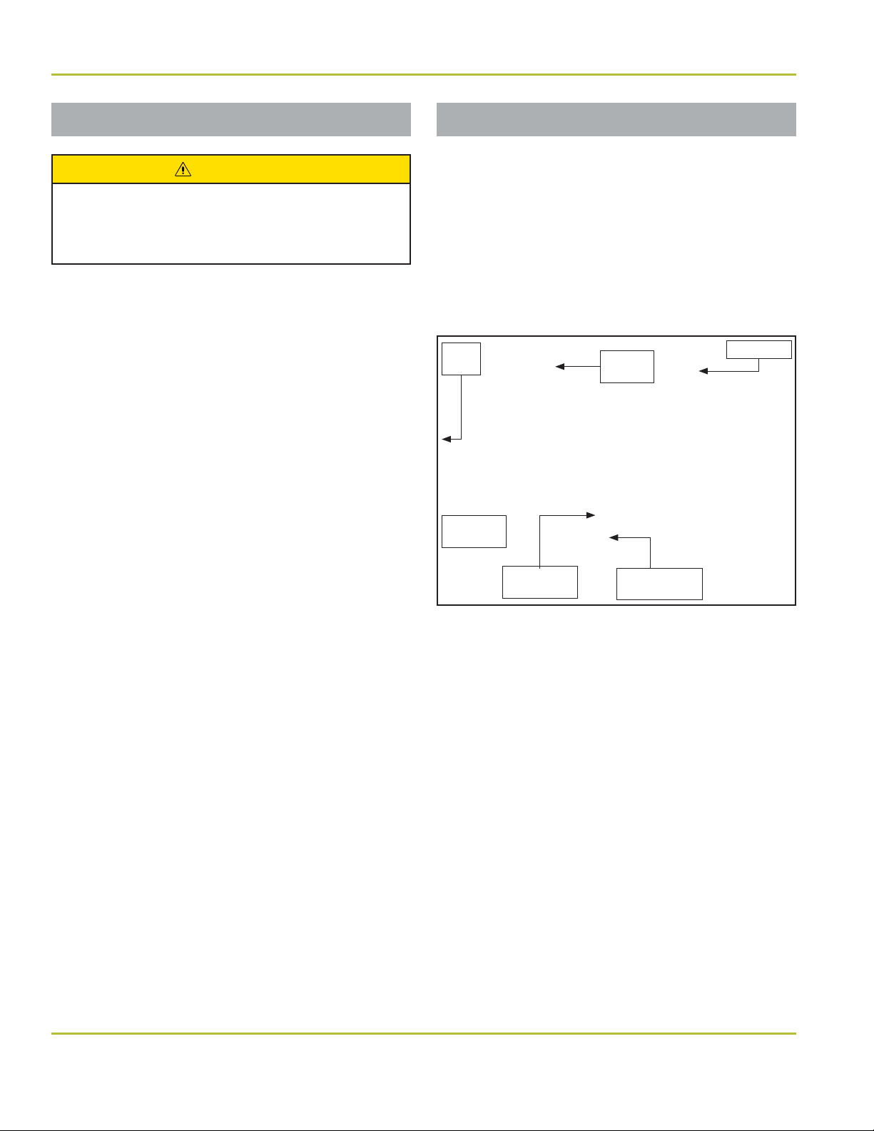
Unpacking Unit Cartons
The CORE Magellan unit components are packaged
and shipped according to the carton diagrams
shown (Figure 3 and Figure 4).
Verify the components packaging contents against
the packing list. All parts supplied are necessary for
proper installation; DO NOT discard any hardware
or components until installation is complete.
NOTE: Cartons may contain empty packing inserts
(even if optional components were ordered).
Magellan Unit Carton Contents
NOTE: If a pre-tubed chair was ordered, items
marked with an asterisk (*) will be on the chair.
• Magellan Unit Support*
• Umbilical*
• Clean Water System
CAUTION
To avoid damage to the carton contents, do
not use a knife or sharp object to open the
packaging.
Unit Post Carton Contents
NOTE: If light post was ordered, entire contents
will be inside light post box.
• Magellan Unit Post
• Installation Hardware
CORE Unit Light
Post (If Ordered)
Installation
Hardware
Magellan
Unit Post
Spacer
• Tray Package
• Utility Service Center
• Foot Control
Clean
Water
Package
Umbilical*
Magellan
Unit
Support*
Figure 3. CORE Magellan unit carton contents
Foot
Control
Tray
Package
Utility
Service
Center
(USC)
Figure 4. CORE Magellan unit post carton contents
Installation Hardware
Pole Pivot Supply Bag Magellan Light Supply Bag
(Optional)
Post Pivot Pin Spacer
Two Thrust Bearings
Four Thrust Washers Two #10 Internal Tooth Lock
3/8" x 2¼" Hex-head Bolt Two 5/6" Heavy Duty Electrical
.382/.393 ID × .683 OD Washer #10-32 × 3/8" Pan-head Screw
13/32" ID × 13/16" OD Washer
Socket Set Screw Light Adapter Cord Assembly
1/4-20 × 3/8" Set Screw
Rubber Pivot Cover
#10-32 × 1" Pan-head Screw
Washers
Clamps
7-1/2" Nylon Cable Tie
www.DentalEZ.com
PN: 2717-267C
866-DTE-INFO
9
9

Section II Preinstallation
CORETM Magellan Unit
Unit Placement
WARNING
• DO NOT position equipment any place
where it would interfere with unplugging
the power cord from the receptacle.
• The plug cannot be located in a position
that requires tools to access.
Utility Service Center (USC)
Parts Included
• Utility Service Center (USC)
• USC Cover
• USC Template
• Bag of Supplies
NOTICE
• Set the USC cover aside until all
installation and testing of the delivery
system is complete.
• DO NOT DISCARD the USC template after
use. Neatly refold it and place in it the
back of this user manual.
Tools Required
• Drill
USC Site Preparation
1. Remove and unfold the full-size USC template
found in the USC carton.
2. Position the USC template according to the
exact layout indicated, making certain correct
distance from base to chair is maintained.
3. Using the USC template, drill four corner
mounting holes for the USC base. DO NOT
secure the base to the oor at this time.
NOTE: For wood or metal oors, drill 5/32" holes.
For concrete oors, drill 1/4" holes and install
plastic anchors.
www.DentalEZ.com
PN: 2717-267C
866-DTE-INFO
10

Section II Preinstallation
Utility Service Center (USC) (Continued)
DentalEZ
®
Equipment
Plumbing Contractor’s Procedure
WARNING
• Before proceeding with plumbing
installation, comply with and maintain all
applicable utility codes and regulations.
NOTICE
• If use of the optional city water system
is planned for in the future, it is highly
recommended to install necessary
components now.
• For reference, a color-coded tubing
diagram is included with this user manual.
Tools Required
• 5/8" Open-end Wrench
USC Installation
NOTE: Items marked with an asterisk (*) are
optional components.
Chair Side
Vacuum
Fitting (Not
Supplied)
(Optional
City Water
Installation
Shown)
Figure 5. Utility service center with optional city water
Air Fitting
Assembly
Drain
Fitting (Not
Supplied)
*Water
Actuator
Valve
Assembly
7. Flush the air and *water lines to remove trash
and debris.
8. Connect the air tting assembly to the air stop
valve as shown in the template. Using a 5/8"
open-end wrench, tighten the nut securely.
9. Connect the *water actuator valve assembly to
the water stop valve as shown in the template.
Using a 5/8" open-end wrench, tighten the nut
securely.
1. Open the USC bag of supplies.
2. Orient the utilities as described in the USC
template and stub through the oor. Vacuum
and drain ttings not supplied; refer to the USC
template for requirements. (Figure 5)
NOTE: Pay close attention to the orientation of the
template to the chair.
3. Sweat the valve adapters to the air and *water
stubs.
4. Apply the appropriate thread sealant to the
valve adapter(s) and install the stop valve(s).
5. Sweat the vacuum elbow to the stub.
6. Sweat the hose connector to the elbow as
applicable and orient as shown in the template.
www.DentalEZ.com
PN: 2717-267C
Electrical Contractor’s Procedure
The electrical contractor is to provide a covered
115V AC receptacle that meets all applicable utility
codes and regulations. For the recommended
location of the 115V AC receptacle, refer to the
USC template.
NOTE: Electrical contractor’s parts are NOT
supplied.
CAUTION
Rating of main circuit breakers should be
20 Amps maximum.
866-DTE-INFO
11
11

CORETM Magellan Unit
www.DentalEZ.com
PN: 2717-267C
866-DTE-INFO
12

Section III Installation
Magellan Unit Support
DentalEZ
®
Equipment
Parts Included
• Magellan Unit Support
• Three Leveling Set Screws
• M16 Bolt
NOTE: If support is preinstalled, proceed to
Pinch Bolt &
Washer
Leveling Set
Screw Holes (3)
Figure 6. Magellan unit support
Step 6
CORE Chair
1. Raise the chair base and back to full UP
position.
2. Disconnect the chair from the power supply.
3. Take o the chair seat upholstery by removing
the ve Phillips-head screws from underneath
the chair (Figure 7).
4. Position the Magellan unit support so that
the lip of the chair rests underneath the lip of
the washer. The mount will hold itself in place
(Figure 8 and Figure 9).
.
Unit Support
Figure 8. Position the unit support under the chair
Figure 9. Slide lip of washer onto lip of chair
5. Install the M16 bolt loosely into the back of the
mount and into the chair.
6. If support is preinstalled, loosen (but do not
remove) M16 bolt to allow for leveling
(Figure 10).
Phillips-head Screws (5)
Figure 7. Remove ve (5) Phillips-head screws
www.DentalEZ.com
PN: 2717-267C
Figure 10. M16 bolt
13
13
Leveling
Set
Screws
M16 Bolt
866-DTE-INFO

Section III Installation
Magellan Unit Support (Continued)
CORETM Magellan Unit
7. Place a level on the Magellan unit support,
parallel with and perpendicular to the chair
center line, then check the level of the unit
support.
NOTE: If leveling is neces
screws until the unit support is level.
8. Tighten M16 bolt (55 foot-pounds).
NOTE: If necessary, repeat steps 5, 6 and 7 after
unit and light are added to re-level.
sary, adjust the 3/16" set
NuSimplicity Chair
1. Raise the base and back to full UP position.
2. Disconnect the chair from the power supply.
3. Take o the chair’s seat by removing the
1/4-20 thumb screw from underneath the seat.
Push the seat toward the back of the chair to
clear the substrate from the slide bosses, then
set the seat aside with all related hardware
(Figure 11).
Substrate 1/4-20 Thumb
Screw
4. Select the following items from the Magellan
unit support hardware package:
• Three 1/2" × 1½" Bolts
• Three 1/2" Lock Washers
• Four 1/2" Flat Washers
• Four 1/2" Shims
• Two 3/8" × 1/2" Set Screws
5. Determine if the two outside 1/2" threaded
hole mounting pads and the Magellan unit
support are level. If the mounting pads or unit
support are not level, select the necessary
amount of 1/2" shims needed to provide a level
condition across the two pads.
6. Position the Magellan unit support so that
the three 1/2" through holes align with the
corresponding threaded holes of the chair
mount casting.
7. Install the two outside 1/2" bolts and lock
washers and the number of 1/2" shims
determined in step 5 through the Magellan
unit support and thread into the chair mount
casting.
Figure 11. Remove the chair seat
NOTE: If inst
DentalEZ chair that is not pre-tubed, continue with
the following instructions. If installing on a pretubed chair,
www.DentalEZ.com
PN: 2717-267C
alling the CORE delivery unit on a
skip steps 4 through 10
.
8. Tighten both outside 1/2" bolts to allow a 3/16"
clearance at the middle 1/2" bolt location.
9. Install the middle 3/8" set screws in the
bottom of the Magellan unit support.
10. Install the middle 1/2" lock washer and 1/2"
bolt, but
14
do not
fully tighten.
866-DTE-INFO

Section III Installation
DentalEZ
®
Equipment
Magellan Unit Support (Continued)
11. Place a level on the Magellan unit support,
parallel with and perpendicular to the chair
center line, then check the level of the unit
support.
NOTE: If leveling is neces
screws until the unit support is level
Leveling Set Screws
Figure 12. Adjust 3/8" set screws if leveling is necessary
sary, adjust the 3/8" set
(Figure 12)
1/2" Bolts
Umbilical Assembly
CORE Chair
NOTE: Provide su icient slack in the umbilical
assembly to avoid stretching when the chair is in
its full UP position.
.
1. From the umbilical bag of supplies, select
the umbilical assembly with the supplied
L-bracket.
2. Route the umbilical between the hydraulic
pump and the control board, then under the
cantilever arm.
3. Route the remainder of the umbilical through
the pivot and up into the chair casting, using
tie wraps to secure.
NOTICE
For tubing connections, see the tubing
diagram in the back of this user manual.
12. Tighten all hardware (55 foot-pounds for 1/2"
bolt).
NuSimplicity Chair
1. From the umbilical bag of supplies, select
the umbilical assembly with the supplied
L-bracket.
2. Route the umbilical between the hydraulic
pump and the control board, then under the
cantilever arm.
3. Tie wrap the umbilical to the bracket
(Figure 13).
L-bracket
Tie Wrap
Figure 13. Tie wrap umbilical to L-bracket
www.DentalEZ.com
PN: 2717-267C
15
15
866-DTE-INFO

Section III Installation
Umbilical Assembly
4. Route the umbilical through the brackets on
the cantilever and secure using tie wraps
(Figure 14).
5. Route the remainder of the umbilical through
the pivot and up into the chair casting using
tie wraps to secure (Figure 15).
6. Using the two 10-32 screws provided, secure
the L-bracket.
7. Leave the base cover o until the foot control
has been installed.
CORETM Magellan Unit
Tie
Wraps
Figure 14. Route umbilical through cantilever brackets
Tie Wraps
Figure 15. Route remainder of umbilical through pivot
www.DentalEZ.com
PN: 2717-267C
866-DTE-INFO
16

Section III Installation
DentalEZ
Finalizing USC Installation
®
Equipment
NOTE: The following instructions for nalizing Utility
Service Center (USC) connections include optional city
water installation.
system only, omit steps 10* through 14*
If installing standard clean water
.
NOTICE
Pictures for the following steps are located on
the next page (Figure 16 - Figure 18).
NOTE: Refer to the tubing diagram (PN: 2662-304)
in the literature packet for all connections.
1. Select the following hardware items:
• Six 1/8" Tubing Clamps
• Three 1/4" Tubing Clamps
2. Remove the cable wrap to expose the tubing
connections of the umbilical assembly
NOTE: If the pump cover and the chair’s lower
cantilever cover are not already removed, take
them o now.
3. Route the foot control tubing into base of the
chair.
4. Find the foot control leads of the chair’s
umbilical assembly numbered 1, 2, 3 and 4
located toward the rear of the chair’s pump
motor assembly.
5. Attach the 1, 2, 3 and 4 leads with the
corresponding numbered connectors of the
foot control tubing.
6. In the USC, attach the hard, red air line
to the air valve tting using the supplied
compression tting (Figure 16, connection A).
7. Connect the 1/8" red tube from the umbilical
to the poppet valve connection opposite the
existing barb assembled to the 1/4" red tube
(Figure 17, connection C).
8. Connect the 1/8" yellow tube from the
umbilical to the poppet valve connection
opposite the existing barb assembled to the
1/8" yellow tube (Figure 17, connection D).
9. Connect the 1/4" red tube, numbered 1, to the
middle barb of the poppet valve in the USC.
Then secure the connection using a 1/4" tubing
clamp. (This is the drive air line for the foot
control) (Figure 17, connection E).
10. *Attach a 1/4" tubing clamp to the rigid 1/4"
green water line of the water regulator.
11. *Use soap to lubricate the 1/4" barb, then
connect the water line to the water valve
actuator (Figure 16, connection B).
12. *Connect the 1/4" green tube of the umbilical
to the connector from the 1/4" green tube of
the water regulator (Figure 18, connection F).
13. *Attach a 1/8" tubing clamp to the 1/8" yellow
air line of the poppet valve.
14. *Use soap to lubricate the barb of the water
valve actuator. Attach the 1/8" yellow line of
the poppet valve to this barb and secure using
a 1/8" tubing clamp (Figure 18, connection G).
15. If a rear assistant’s arm is installed, slip the
vacuum hose from the chair over the vacuum
elbow in the USC (Figure 18, connection H).
16. If an optional ber optic electrical system
is installed, attach the electrical leads of
the power pack transformer to the adapter
harness. Attach the electrical leads to the
matching connector on the main harness.
17. Route the main harness through the 5' × 1¾"
corrugated ducting hose to the inside of the
chair pump cover (for future connections if
necessary).
18. In the USC, open the air/water stop valves and
check for leaks.
www.DentalEZ.com
PN: 2717-267C
17
17
866-DTE-INFO

Section III Installation
Finalizing USC Installation (Continued)
*B
CORETM Magellan Unit
*Water Regulator
A
Vacuum
Elbow
Figure 16. Optional city water layout
C
D
E
Figure 17. Typical installation
Air
Regulator
*F
www.DentalEZ.com
PN: 2717-267C
*G
H
Figure 18. Typical installation
866-DTE-INFO
18

Section III Installation
Magellan Unit Post
Pivot Cover
Pivot Cover
DentalEZ
®
Equipment
3/8" Hex-head Bolt
3/8" Lock Washer
Magellan Unit Post
Tools Required
• 1/8" Hex Key
1. Select the following hardware package items
(Figure 19):
• 1/4" x 3/4" Set Screw
• 1/4" x 3/8" Set Screw
• 3/8-16" × 2-14" Hex Head Screw
• 3/8" Flat Washer
• 3/8" Lock Washer
3/8" Flat Washer
Post Pivot Pin
Slot
Unit Pole
Thrust Bearing
Unit Support
1/4-20 × 3.8"
Set Screw
Figure 19. Magellan unit post hardware
Thrust Washers
1/4-20 × 3.8"
Set Screw
Post Stop
(Ground Point)
5. Position a thrust washer onto the at member
of the Magellan unit pole and post pivot pin.
• Four Thrust Washers
• Two Thrust Bearings
• Pivot Cover
• Post Pivot Pin
• Post Stop
2. Place a thrust washer on the bearing surface
of the post pivot pin.
3. Apply lubricant to a thrust bearing and install the
bearing, followed by a second thrust washer.
4. Insert post pivot pin and bearing stack into
unit pole.
www.DentalEZ.com
PN: 2717-267C
6. Apply lubricant to the second thrust bearing
and install followed by a thrust washer.
7. Insert the post pivot pin and unit pole with thrust
bearing and washers into the unit support.
NOTE: Engagement is a slip
t, provided the
Magellan unit post is held in alignment.
CAUTION
To avoid damage to the pivot bushing, do not
use force when installing the pivot pin into the
Magellan unit post.
866-DTE-INFO
19
19

Section III Installation
CORETM Magellan Unit
Magellan Unit Post (Continued)
8. Make sure the pivot pin slot faces the side of
the unit support having the tapped hole.
9. Seat the pivot mount until its head is in full
contact with the bottom and sides of the
Magellan unit support.
10. Use 3/8-16" × 2-1/4" hex head screw,
lockwasher and at washer to secure post
pivot pin to unit support.
11. Locate the 1/4-20 × 3/4" long set screw in the
threaded hole on the Magellan unit support.
Then tighten the set screw to prevent the
pivot pin from rotating.
12. Place a 1/4-20 × 3/8" long set screw into
the threaded hole in the at member of the
Magellan unit post.
13. Engage the 1/4-20 × 3/8" set screw with a 1/8"
hex key to deform the internal bushing against
the pivot mount until a 3-lb force is required to
rotate the unit post.
14. Install the pivot cover over the bolt head.
Delivery Head
Delivery
Head
Tools Required
• 5/64" Hex Key
1. Remove the packaging from the delivery
head along with the adjustable arm and the
umbilical assembly.
2. Feed the umbilical assembly into the unit post,
ensuring that the leading end of the
umbilical assembly (with the protective spiral
end) does not catch on the open access slot
or weld seam of the unit post’s at joint.
www.DentalEZ.com
PN: 2717-267C
3. After the umbilical assembly is completely
installed in the unit post, insert ex arm into
unit post.
4. Secure the bearing arm support with a set
screw using 5/64" hex key.
5. Match and connect the tubes and wires
from the Magellan arm umbilical assembly
to the tubes and wires of the chair umbilical
assembly. Refer to tubing diagram (PN: 2662-
304).
6. For touchpad control equipped, route harness
through chair, connect terminal to main
control board, and coil excess harness.
866-DTE-INFO
20

Section III Installation
USC Base Rear Assistant
1. Position the USC base over the four corner holes
that were drilled during preinstallation.
2. Secure the base using four #10 screws.
NOTICE
If previous utilities interfere with the USC
base internal bracing, modi cation may be
necessary.
DentalEZ
Rear
Assistant
CORE Chair
Tools Required
®
Equipment
• 1/4" Hex Key
• 9/16" Socket
NOTE: Remove seat cushion, if necessary.
1. Place the chair in its full upright position.
2. Attach the rear assistant mount to the
platform below the chair brake with two
shoulder screws. Tighten in place with 1/4" hex
key (Figure 20).
NOTE: Recessed holes must be facing upward.
www.DentalEZ.com
PN: 2717-267C
Figure 20. Attach rear assistant mount to platform
21
21
866-DTE-INFO

Section III Installation
Rear Assistant (Continued) Assistant’s Arm (Optional)
3. Remove the cap and nut from the shoulder
bolt located in the link of the rear assistant’s
arm (Figure 21).
4. Place the link of the rear assistant’s arm on
Cap
plastic washer. (Be sure to keep the
Shoulder Bolt
washer/ spring washers in the
same orientation.)
Figure 21. Remove cap and nut from shoulder bolt
5. Thread the shoulder bolt into the bracket and
tighten the bolt securely using 1/4" hex key.
T
est that the arm rotates without the bolt
head turning.
top of the bracket and
Bracket
Link
Washer
CORETM Magellan Unit
Rear
Assistant’s
Arm & Mount
Tools Required
• 1/4" Hex Key
6. From the underside of the bracket, install the
nut on the shoulder bolt and tighten securely
with 9/16" socket.
7. Replace the cap in the link.
8. Pass the tubing and wires from the assistant’s
arm through the strain relief bushing in the
cantilever cover.
9. Pass the tubing wires through the wire
bracket.
10. Connect the 5/8" ID vacuum hose of the rear
assistant’s arm to the 5/8" ID vacuum hose of
the chair by sliding it over the connector of the
chair’s ducting hose.
11. Cut o excess vacuum tubing, if necessary.
• 9/16" Socket
NOTE: Remove seat cushion, if necessary.
1. Place the chair in its full upright position.
2. Remove the cap and nut from the shoulder bolt
located in the link of the rear assistant’s arm
(Figure 22).
Cap
Bracket
Shoulder Bolt
Figure 22. Remove cap and nut from shoulder bolt
Link
Washer
3. Place the link of the rear assistant’s arm on
top of the bracket and plastic washer. (Be
sure to keep the washer/spring washers in the
same orientation.)
www.DentalEZ.com
PN: 2717-267C
4. Thread the shoulder bolt into the bracket and
tighten the bolt securely with 1/4" hex key.
Test that the arm rotates without the bolt
head turning.
866-DTE-INFO
22

Section III Installation
DentalEZ
®
Equipment
Assistant’s Arm (Opt) (Continued) Assistant’s Instrumentation
5. From the underside of the bracket, install the
nut on the shoulder bolt and tighten securely
with 9/16" socket.
6. Replace the cap in the link.
7. Pass the tubing and wires from the assistant’s
arm through the strain relief bushing in the
cantilever cover.
8. Pass the tubing and wires through the wire
bracket.
9. Connect the 5/8" ID vacuum hose of the rear
assistant’s arm to the 5/8" ID vacuum hose of
the chair by sliding it over the connector of the
chair's ducting hose.
10. Cut o excess vacuum tubing, if necessary.
11. Refer to tubing diagram (PN: 2662-304) for
air/water connections.
12. For touchpad control equipped, route harness
through chair, connect terminal to main
control board, and coil excess harness.
Saliva Ejector (SE)
1. Connect the SE valve to the 5/16" OD SE tubing
(Figure 23).
SE Valve
5/16" OD SE Tubing
Figure 23. Connect SE tubing and SE valve
2. Hang the SE valve in the instrument holder.
3. Connect the SE tubing to the open 1/4" port
under the solids collector in the assistant’s
arm.
High Volume Evacuator (SE)
1. Connect the HVE valve to the 5/8" OD tubing
(Figure 24).
HVE Valve
www.DentalEZ.com
PN: 2717-267C
5/8" OD Tubing
Figure 24. Connect HVE valve and OD tubing
2. Hang the HVE valve in the instrument holder.
3. Connect the tubing to an open 1/2" port under
the solids collector in the assistant’s arm.
4. If an optional second high volume evacuator
valve is used, remove plug.
Air/Water Syringe
NOTE: The syringe for the delivery head is factory
installed.
866-DTE-INFO
23
23

Section III Installation
CORETM Magellan Unit
Fiber Optic Tubing (Optional) Fiber Optic Electrical (Optional)
NOTE: The ber optic tubing is factory installed. NOTE: The ber optic electrical wiring is factory
installed. To complete installation, connect the
ber optic wires from the unit head/arm to the
ber optic transformer in the utility service center
(USC). Plug in the ber optic transformer.
www.DentalEZ.com
PN: 2717-267C
866-DTE-INFO
24

Section III Installation
Light or Monitor Post (Optional)
DentalEZ
®
Equipment
Light
Post
Tools Required
• 1/8" Hex Key
1. Select the following hardware package items
(Figure 25):
• 1/4" × 3/4" Set Screw
• 1/4" × 3/8" Set Screw
• 3/8-16" × 2¼" Hex Head Bolt
• 3/8" Flat Washer
• 3/8" Lock Washer
Post Stop
Thrust
Washers
1/4" × 3/8"
Set Screw
1¼" Brass Bushing
Thrust
Washers
Slot
3/8" Flat Washer
3/8"-16 × 2¼"
Hex Head Bolt
Pivot Cover
1/4" × 3/4"
Set Screw
Counter Bore
Thrust Bearing
Light Arm or
Monitor Arm
Thrust
Bearing
Post Pivot Pin
3/8" Lock
Washer
• Four Thrust Washers
• Two Thrust Bearings
• Pivot Cover
• Post Pivot Pin
• Post Stop
2. Raise the chair base to its upper travel limit
and disconnect the chair power.
3. Apply lubricant to both sides of all thrust
washers and thrust bearings.
4. Place a thrust washer, bearing and another
thrust washer onto the pivot pin. Then insert
www.DentalEZ.com
PN: 2717-267C
Figure 25. Light/monitor post hardware
the pivot pin and bearing stack through the
1-1/4" brass bushing at the end of the light/
monitor post. Place another thrust washer,
bearing and thrust washer onto the pin.
5. While holding the bearings and pin in the post,
align the machined hole in the pivot pin with
the pin in the chair support’s bottom counter
bore. Then adjust the unit post and pin so the
pin will slide into the counter bore.
NOTE: Engagement is a slip
t, provided the
Magellan light/monitor post is held in alignment.
866-DTE-INFO
25
25
Section III Installation
CORETM Magellan Unit
Light or Monitor Pole (Opt) (Cont)
CAUTION
To avoid damage to the pivot bushing, do not
use force when installing the pivot mount into
the light/monitor post.
6. Seat the pivot mount until its head is in full
contact with the bottom and sides of the
Magellan unit support.
7. Make sure the pivot pin slot faces the side of
the unit support having the tapped hole.
8. While holding the unit post in position, install
the 3/8"-16 × 2¼" hex head bolt with 3/8" lock
and at washers through the pin so that it
threads into the chair support, then tighten
the bolt enough to remove most clearances
between the bearings.
9. Install the 1/4" × 3/4" set screw into the
threaded hole on the Magellan unit support,
then tighten the set screws to prevent the
pivot pin from rotating.
Power Module (Optional)
1. Unplug all cords from the receptacle in the
USC.
NOTE: See the power module system wiring
diagram provided with this user manual for
connections.
2. Connect the main wiring harness to the power
module (Figure 26).
1/8"
Barb
Main
Harness
1/8" Yellow
Line
Figure 26. Connect main harness to power module
Power
Module
1/8" Yellow
Line “T”
Umbilical
10. Finish tightening the bolt in the pin until all the
clearance between the bearings is removed
and the post moves freely, then re-tighten the
set screw.
11. Place a 1/4" × 3/8" set screw into the threaded hole
in the at member of the Magellan unit post.
12. Engage the set screw with a 1/8" hex key to
deform the internal bushing against the pivot
mount until a 3-lb force is required to rotate
the unit post.
13. Install the pivot cover over the bolt head.
www.DentalEZ.com
PN: 2717-267C
3. A “T” must be spliced into the 1/8" yellow
air line near the poppet valve. Then connect
the open end of the “T” to the barb of the
power module using a section of 1/8" yellow
air line and two tubing clamps. If necessary,
cut a section of 1/8" yellow air line out of the
umbilical to make connection.
4. After checking all the plug connections,
reconnect the power plug and surge protector
into the receptacle in the USC.
866-DTE-INFO
26

Section III Installation
Power Module (Opt) (Cont)
CAUTION
To avoid damage to the unit, the surge
protector supplied with the power module
must be used at all times.
5. Pass the green wire of the main harness
through the umbilical and ground it to the
power module, USC base or chair (Figure 27).
NOTE: It may be necessary to remove an existing
screw and reinsert the screw with the green
ground wire attached.
NOTE: Make sure the air valve in the USC is open.
DentalEZ
®
Equipment
Green
Ground
of Main
Harness
Figure 27. Pass green wire of harness through umbilical
6. At the delivery head, turn master switch to
ON and ensure power is available at power
module.
NOTICE
For power supply options, the Power Module
or the XP Power Supply must be chosen.
www.DentalEZ.com
PN: 2717-267C
27
27
866-DTE-INFO

CORETM Magellan Unit
www.DentalEZ.com
PN: 2717-267C
866-DTE-INFO
28

Section IV Testing
Delivery System
DentalEZ
®
Equipment
NOTICE
• Before testing the delivery system, make
sure the shipping tie wrap is removed
from the adjustable arm pivot area at the
delivery head.
• The air regulator is factory preset to
delivery 551.5 kPa (80 PSI). The water
regulator is preset to deliver 275.8 kPa
(40 PSI).
Tools Required
• Phillips-head Screwdriver
• 1/16" Hex Key
• 1/4" Hex Key
Utility Service Center
Air and Water Filter/Regulators
If the regulators are not set, do the following
adjustment process:
1. Pull the locking knob.
2. Turn the adjustment knob on each regulator
until the correct pressure reading is reached
(clockwise to increase or counterclockwise to
decrease).
3. When nished, push the locking knob down.
Adjustable Arm
To check the maneuverability of the CORE
adjustable arm, do the following:
1. Depress and hold the brake release button.
2. Lift the adjustable arm or lower it into the
desired position.
1. Turn ON all services supplying the USC.
2. Open the air and water manual stop valves by
turning the knobs counterclockwise.
3. Inspect all joints and connections for leaks.
4. Plug in any transformers in the USC into an
electrical outlet.
5. Flip the master switch forward to turn ON unit
(Figure 28).
OFF ON
Master
Switch
Figure 28. Turn master switch to ON position
6. Inspect for leaks in the service console,
cuspidor and delivery head.
3. Release the brake release button (Figure 29).
Brake
Release
Button
Brake
Release
Handle
Figure 29. Delivery head brake release
4. To adjust ex arm drift, remove ex arm
cap near the post using a Phillips-head
screwdriver and 1/16" hex key. With cover
removed, push unit in the furthest downward
position to gain access to the adjustment
screw. Using a 1/4" hex key, adjust drift by
rotating this screw. Once adjustment is
complete, reassemble ex arm cap.
www.DentalEZ.com
PN: 2717-267C
29
29
866-DTE-INFO

Section IV Testing
CORETM Magellan Unit
Syringe
If the unit is equipped with a syringe, rst depress
the air button and then the water button to test
the ow.
Foot Control & Handpieces (Opt)
Coolant Water Lines
1. At the foot control, ip the toggle to WET
(Figure 30).
WET/DRY
Toggle
Figure 30. Flip toggle switch to WET position
• Before connecting handpieces, all air must
be purged from the coolant water lines to
allow the system to function properly.
Dry Wet
Chip Air
CAUTION
Valve
2. Purge air from the coolant water lines on each
handpiece as follows:
a. Turn the water coolant valve
counterclockwise to its full, open position.
b. Remove the handpiece tubing from holder.
Water Adjustment Valves
Figure 31. Adjustment valves
c. While facing the deliver head, start with the
handpiece tubing on the far left, then fully
depress the foot control to allow water to
ow into a sink or other container.
www.DentalEZ.com
PN: 2717-267C
866-DTE-INFO
30

Section IV Testing
Foot Control & Handpieces (Opt) (Continued)
DentalEZ
®
Equipment
d. As the water is owing, continue the
purging operation of the remaining tubings
(moving from the left tubing to the right
tubing).
e. Allow water to ow freely from all tubings
until all air has escaped.
3. Attach the handpieces to the tubing as follows:
a. Slide the connector nut down along the
tubing to expose the handpiece adapter.
b. Carefully align and insert the handpiece
swivel base into the adapter.
c. Replace and tighten the connector nut to
complete installation.
Air Pressure
1. Flip the toggle to DRY at the foot control.
2. To adjust the individual handpiece drive air
pressure to the manufacturer’s speci cations,
do the following procedure:
a. Remove the handpiece from its holder.
c. Hold the handpiece, fully depress the foot
control, and observe the amount of air
pressure delivered to the handpiece.
d. Locate the air pressure adjustment screws
on the bottom of the delivery head chassis
(Figure 33).
Air Pressure Adjustment
Figure 33. Air pressure adjustment screws
e. Turn the air pressure adjustment screw
on the control valve of the appropriate
handpiece (counterclockwise to increase
pressure, clockwise to decrease pressure)
until the handpiece manufacturer’s correct
speci cation registers on the pressure
gauge.
b. Insert an air pressure gauge as indicated
(Figure 32).
Handpiece
Adapter
Tubing
(Insert
Nut
Figure 32. Insert air pressure gauge
www.DentalEZ.com
PN: 2717-267C
Air Pressure
Gauge Here)
3. Repeat step 2 (a-e) to set the pressure for
each handpiece.
Chip Air Foot Control (If Equipped)
If the handpiece utilizes coolant air, a burst of air
should be delivered to the handpiece when the
chip air valve is depressed.
866-DTE-INFO
31
31

Section IV Testing
CORETM Magellan Unit
Foot Control & Handpieces (Opt)
Flush Valve
1. Remove the handpiece from its holder.
2. Activate the ush valve (Figure 34).
3. Operate each handpiece for 30 seconds into a
cuspidor, sink or open vacuum line.
Flush Valve
Figure 34. Flush valve
Other Optional Features
Fiber Optics
Follow the test procedures outlined in the
instructions included in each ber optic
handpiece package.
Assistant’s Vacuum Accessories
Evacuate one cup of water (8 oz. each) through
the saliva ejector and the high-volume evacuator.
NOTICE
After all nal testing is complete, install the
USC cover.
www.DentalEZ.com
PN: 2717-267C
866-DTE-INFO
32

Section V Operation
Delivery Head
DentalEZ
®
Equipment
WARNING
• To prevent possible injury due to
accidental operation, do not leave young
children unattended.
• Do not place objects weighing more than
10 pounds on the delivery head/tray.
Master Switch Control
The master switch (located on the underside of
the delivery unit) controls the ON/OFF functions
of air, water and electricity to the entire unit. Flip
the master switch forward to turn ON unit
(Figure 35).
OFF ON
Master Switch
Figure 35. Flip master switch to ON
Delivery Head Positioning
The horizontal and vertical location of the delivery
head can be varied by doing the following:
• To vary the horizontal location, push or pull the
brake handle (Figure 37).
• To raise the delivery head, lift up the brake
handle with the brake button pressed.
• To lower the delivery head, make sure the
brake is o and pull the head down.
• When positioned correctly, release the brake
button.
Brake Release
Button
Brake
Release
Handle
Figure 37. Delivery head brake release
NOTICE
• IMPORTANT: At the end of each workday
and anytime the unit is unattended, make
sure the master switch is in OFF position.
Oil Collector/Filter
The oil collector/ lter is designed to collect oil
from the handpiece exhaust air. Periodically check
the lter for cleaning or replacement by removing
the cover and inspecting the lter (Figure 36).
Oil Filter Housing
Figure 36. Oil lter housing
www.DentalEZ.com
PN: 2717-267C
33
33
866-DTE-INFO

Section V Operation
Syringe Foot Control
CORETM Magellan Unit
The syringe is designed to deliver air or water, or a
mixture of air and water, as required.
• To deliver water only, press the button on the
syringe marked with a water drop symbol.
• For air only, press the button on the syringe
with no marking.
• To get a spray mixture of air and water, press
both buttons simultaneously.
The speed of the handpiece is controlled by
depressing the disc located on the foot control
(Figure 38).
WET/DRY
Toggle
Figure 38. Foot control disc
• A light pressure on the foot control disc
causes a slow speed.
• Full pressure on the disc causes the
handpiece to operate at full speed.
Dry Wet
Chip Air
Valve
NOTE: The optional coolant water spray ON/OFF
function is also controlled by using the toggle
located on the foot control as described above.
Chipblower
If the handpiece utilizes coolant air, the
chipblower is used to blow debris away from the
cutting site by creating an air blast through the
handpiece without causing the bur to rotate. To
operate the chip blower, depress and hold down
the valve on the upper right of the foot control.
Optional Fiber Optics
The ber optics control is automatically activated
by operating the handpiece using the foot control.
NOTE: When the foot control is released, the ber
optics light will stay on for approximately ten (10)
seconds to allow inspection of the cutting site.
www.DentalEZ.com
PN: 2717-267C
866-DTE-INFO
34

Section V Operation
DentalEZ
®
Equipment
Assistant’s Vacuum Accessories Clean Water System
WARNING
Do not hang objects weighing more than
5 pounds on the assistant’s arm.
The standard instrumentation for an assistant’s
arm is one High Volume Evacuator (HVE), one
Saliva Ejector (SE) and a three-way syringe.
(Syringe operating instructions on p. 34.) Optional
features include an additional HVE.
NOTE: The assistant’s arm pivots to allow
positioning of the instruments for easy access.
HVE and SE
The ow of vacuum through the HVE and SE is
controlled by a lever valve (Figure 39).
• Pushing the lever forward toward the tip
opens the vacuum.
Operation of the clean water system is as follows:
• Flip the toggle switch to the ON position (Figure
40).
• If optional city water is in use, ip the toggle
switch to change usage from city water to
bottle water.
• To remove the bottle, rst ip the toggle
switch to the OFF position, then unscrew it
from the assembly.
Toggle
Switch
• Moving the lever toward the hose end
decreases the vacuum ow.
• To close the valve, move the lever all the way
toward the hose end.
HVE Lever Valve
Close Open
SE Lever Valve
Close Open
Figure 39. HVE and SE lever valves
Bottle
Figure 40. Clean water system
NOTICE
This dental water delivery system is equipped
with BioFree
properties built in to protect it.
TM
tubing containing antimicrobial
www.DentalEZ.com
PN: 2717-267C
35
35
866-DTE-INFO

CORETM Magellan Unit
www.DentalEZ.com
PN: 2717-267C
866-DTE-INFO
36

Section VI Care
Cleaning
DentalEZ
®
Equipment
CAUTION
Do not use abrasive cleaning agents.
The CORE delivery unit should be cleaned as
follows:
• Wipe frequently with a damp, lint-free cloth.
• Use a neutral detergent to clean stains.
• At the end of the day, turn the master
ON/OFF valve to the OFF position and clean
instrumentation.
• Each morning, turn the master valve ON and
check the air and water systems for proper
operation using the three-way syringe.
NOTE: It is recommended that puncture-resistant
nitrile gloves be worn for the following procedures.
High-Volume Evacuator (HVE)
With the high-volume evacuator vacuum valve
in the OFF position, disconnect the valve. Using
a brush, clean the interior of the valve under a
faucet, and rinse thoroughly.
Solids Collector
To clean the solids collector located at the
instrument end of the assistant’s arm, do the
following:
1. Push the lever on the saliva ejector upward to
equalize pressure.
2. Remove the lid by lifting it straight up.
3. Grasp the stem on the basket and lift the
basket straight up.
4. Throw away and replace with new basket.
Clean Water System
Empty the bottle at the end of each day, then
before the day’s rst procedure, ll it with fresh
water.
Water Lines
To prevent contamination, maintain clean water
lines and regenerate the BioFreeTM tubing. (Refer
to the included packet.)
Air/Water Pressure Regulator Filter
Saliva Ejector (SE)
Disconnect the saliva ejector valve from the
tubing and repeat the procedure described for the
HVE.
NOTE: After cleaning the HVE, SE and solids
collector, evacuate two cups of SlugBusterTM
vacuum line cleaning solution (one cup each)
through the HVE and SE to sanitize the system.
NOTICE
Cleaning brushes and SlugBusterTM can be
ordered through DentalEZ dealers.
www.DentalEZ.com
PN: 2717-267C
The lter element in the air pressure regulator is
intended to keep moisture out of the unit and the
lter element in the water pressure regulator is
intended to keep contaminants out of the unit. It
is recommended to replace these lters at least
once a year. If the lter element is clogged, it will
visibly look dirty, causing a pressure and ow
drop. In this case, the element should be replaced.
866-DTE-INFO
37
37

Section VI Care
Disinfecting
CAUTION
• Use extreme caution when selecting the
proper chemical disinfectant for the CORE
Magellan unit.
• Avoid using disinfectants in spray
containers because they may cause
premature staining, discoloration and/or
damage to the unit.
• Do not use disinfectants that contain:
▪ Iodophors
▪ Glutaraldehydes
▪ Phenols
CORETM Magellan Unit
▪ Sodium Hypochlorites
▪ Alcohol (on plastic surfaces)
Liquid disinfectants are recommended for use on
the delivery system external surfaces and should
be applied using a soft, clean cloth.
TM
Cavicide
Cavicide is the recommended disinfectant for
use on all ext
from MetrexTM Research
ernal surfaces. Cavicide1
TM
is not
recommended for use.
Cavicide and CaviCide1 are trademarks of Metrex Research, LLC.
www.DentalEZ.com
PN: 2717-267C
866-DTE-INFO
38

Section VII User Service Information
Troubleshooting
DentalEZ
®
Equipment
A full color, fold-out tubing diagram of the CORE
WARNING
Magellan unit is provided with this manual.
• Before servicing, always disconnect the
The following charts should be used when
troubleshooting CORE Magellan unit problems.
If these suggested troubleshooting procedures
do not resolve the problem, refer to the Service
Instruction section that follows.
external power by unplugging the unit
from the power receptacle.
• Exercise extreme caution when
troubleshooting the electrical
components of the CORE Magellan unit.
When testing, always disconnect the
external power. When electrical power
NOTICE
The DentalEZ Technical Service Department is
available to supply service personnel with any
additional information or instructions needed to
repair or maintain the dental delivery system.
is required, safety precautions must be
followed.
• Do not modify this equipment without
authorization from the manufacturer.
• The power module power cord is not
replaceable by service personnel.
Delivery Head
Symptom Possible Cause(s) Solution
Unit will not
turn on
Unit has no
electric power
Unit has no air Unit is not turned on Ensure master toggle valve is in ON position.
No water
(handpiece and
syringe)
Air in coolant
water
No air to master switch Open stop valve in oor utility box.
Open and adjust air regulator to 80 PSI.
Check for pinched red 1/8" tubing in arms.
Faulty master switch Turn switch on and verify air ow.
Faulty air pilot valve Verify on air supply to top tting of valve.
If air is present at top tting of valve, verify air to foot control tubing. If
no air at tubing, valve is defective.
No building power Check main circuit supply.
Faulty electric switch Contact electrician.
Improper outlet voltage Verify proper outlet voltage in USC.
Air stop valve is closed Turn stop valve on and verify 80 PSI on air gauge.
Pinched air line Check for pinched or restricted 1/8" red tubing from oor utility box to
the master switch.
Faulty air pilot valve Check barbs for blockage. If none, replace valve.
Water toggle is in OFF position Place the CMU switch plate toggle in ON position.
No water in clean water bottle Fill bottle.
Pressure regulator not adjusted Ensure clean water system gauge reads 40 PSI.
No air to bottle water system Check for pinched or restricted airline.
Slide clamp is clamping line Move clamp to allow water ow through line.
Unit has not been purged Purge water lines (Section IV Testing, Foot Control & Handpieces)
Faulty water control valve If unit was purged, replace water control valve.
www.DentalEZ.com
PN: 2717-267C
39
39
866-DTE-INFO

Section VII User Service Information
Troubleshooting (Continued)
Handpiece
Symptom Possible Cause(s) Solution
No drive air Drive air ow adjustments on pinch valves
are closed
Faulty handpiece holder valve If valve does not release with handpiece out of holder and tubing to
Faulty foot control Depress foot control if no air is present, repair or replace foot control.
Pinched or restricted tubing Straighten or replace the 1/4" red tubing.
No ber-optic light
at handpiece
No coolant water
at any handpiece
Water dribbles
from handpiece
while in holder
Water dribbles
from handpiece
after foot control
is released
No coolant air to
handpiece
Power transformer is not plugged in Plug transformer into designated receptacle in USC.
Internal wires in control head and
post-mounted console are not connected
No signal air to ber optic lamp control Check pinched or restricted tubing.
Faulty transformer Check output for 22-23 VAC.
Faulty ber optic control Fiber optic controls have a calibration range of 2.5 to 6.0V DC. Check
Faulty bulb Replace bulb.
No signal air to receptacles in the USC Check for pinched or restricted tubing.
Coolant water adjustment valve closed. Turn valve counterclockwise to open valve.
Water toggle on foot control is in the OFF
position
Water toggle on clean water system is in the
OFF position
Slide clamp is in clamped position Slide clamp so it moves freely on tubing.
Water bottle empty Fill water bottle.
Pressure too low on clean water system Verify clean water system pressure gauge reads 40 PSI and adjust
Pinched or restricted tubing Straighten or replace tubing.
Faulty handpiece holder Repair or replace holder.
Pinched or restricted tubing to holder Straighten or replace tubing.
Pinch valve diaphragm is leaking Replace diaphragm.
Low air pressure Ensure air regulator gauge in oor box reads 80 PSI.
Low air pressure Ensure air regulator gauge in oor box reads 80 PSI.
Faulty water control valve Depress foot control then release. Remove black tubing from water
Faulty water relay in foot control Turn unit o . Open foot control and inspect water relay block. If piston
Pinched or restricted tubing from foot control Straighten or replace tubing.
Slide clamp is in clamped position Reposition slide clamp so it moves freely on tubing.
Pinched or restricted tubing Straighten or replace tubing.
Turn adjustments screw counterclockwise to adjust drive air pressure.
Set to manufacturer's recommended pressure.
holder is not restricted, replace hanger valve.
Check connections in control head and post-mounted console.
for proper voltage according to the handpiece manufacturer’s
recommendations.
Flip toggle to the right for the ON position.
Flip toggle to the ON position.
accordingly.
control valve. If dribble continues, replace valve.
is not damaged and is moving freely, stretch the spring. Reassemble
and retry foot control.
CORETM Magellan Unit
www.DentalEZ.com
PN: 2717-267C
866-DTE-INFO
40

Section VII User Service Information
DentalEZ
Troubleshooting (Continued)
Arm System
Symptom Possible Cause(s) Solution
Horizontal arms
drift left or right
Unit head is not
level from front
to back.
Adjustable arm
does not hold
position.
Symptom Possible Cause(s) Solution
Bowl rinse has no
water
Bowl rinse runs
continuously
Bowl does not
drain or drains
slowly
No water ows
from cup to ll
Unit is not properly leveled Verify unit is level. Also, verify arms are properly seated. Adjust
tension or set screws as needed.
Pivot is not properly adjusted Remove end cap cover and adjust bolt as necessary.
Improper adjustment With nothing on delivery head, adjust bolt at the rear of the ex arm so
unit stays in place.
Faulty brake switch Make sure air is running through the brake toggle when the brake is on.
No air to brake switch Ensure unit master toggle is in ON position.
Cuspidor (Optional)
Delivery HeadDelivery Head
Stop valve closed Open stop valve inside USC compartment.
Pinched or restricted 1/4" green tubing from
oor utility box to post-mounted console
Water actuator valve in oor utility box is not
activated
Bowl rinse button not working Verify air signal is present at the bowl rinse poppet valve on the
Bowl rinse actuator valve in cuspidor is not
opening
Water pressure is too high Set water pressure gauge at 40 PSI.
Bowl rinse actuator valve is stuck open Check the valve in the cuspidor for air signal. If air is present, check
Restricted or pinched drain line Examine drain line and free and obstructions
Restricted or pinched vent line Examine vent line and free any obstructions.
Cup ll button is not working Check actuator valve in cuspidor for air signal at cup ll actuator valve
Cup ll actuator valve in cuspidor is not open Verify signal is present at actuator when cup ll button is depressed. If
Check for restricted or obstructions and free accordingly.
Verify unit master switch is turned ON.
Verify air signal is present at valve on water line.
Verify regulator is open and pressure is at 40 PSI.
cuspidor when the bowl rinse button is depressed.
Verify air signal is present at actuator valve when button is depressed.
At actuator valve in cuspidor, check for water supply from oor utility
box. Also, ensure water passes through the valve when the rinse
button is depressed.
bowl rinse poppet valve. If air is not present, replace actuator valve.
in post-mounted console when button is depressed.
Check for pinched airlines.
air and water are present, replace valve.
®
Equipment
www.DentalEZ.com
PN: 2717-267C
41
41
866-DTE-INFO

Section VII User Service Information
Service Instruction Disposal of Equipment
CORETM Magellan Unit
If the area of concern is not addressed in this
manual, contact your local DentalEZ full-service
dealership at 866-DTE-INFO (866-383-4636). See
Limited Warranty.
Please have the following product information
available. Information may be found on the
product model/serial number label (Figure 41):
• Model Name:
• Model Number:
• Serial Number:
• Date of Installation:
• Dealer:
Model/Serial
Number Label
Disposal and Decommissioning of
DentalEZ Products
NOTE: All local regulatory requirements for
disposal and decommissioning of equipment
apply.
• Electrical Salvage
Remove all circuit board and electrical cabling
for recycle as electrical salvage.
• Metal Salvage
Remove all aluminum and steel components
for recycle as metal salvage.
• Plastic Salvage
Remove all plastic components for recycle as
plastic salvage.
• Biologically Contaminated Salvage
Figure 41. Model/serial number on CORE delivery head
Cuspidor, waste lines from the cuspidor, and
the oral extraction lines should be handled
with precaution and disposed of appropriately.
• Non-Salvage Components
All other material unsuitable for recycling
should be disposed of properly.
For speci c questions regarding material
type, contact DentalEZ customer service. For
decommissioning information on associated
equipment from other manufacturers, refer to the
documentation from the manufacturer.
www.DentalEZ.com
PN: 2717-267C
866-DTE-INFO
42

Section VIII Parts Lists/Diagrams
DentalEZ
®
Equipment
Utility Service Center
# Part/Kit Name Part/Kit No.
1* Water Actuator Valve 3801-637
2 Stop Valve 3800-960
3 Air Regulator 3801-638
4 Air Regulator Gauge Repl. Kit, Watts 3802-266
5* Water Regulator Gauge Repl. Kit, Watts 3802-269
6* Water Pressure Gauge 3800-533
7 Air Regulator Bowl, Watts 3802-267
8* Water Regulator Bowl, Watts 3802-268
9* Water & Air Regulator Repair Kit, Watts 3802-273
10* Water Regulator Filter, Watts 3802-270
11 Air Regulator Filter, Watts 3802-271
12 Regulator Retainer, Watts 3802-272
13 Poppet Valve 3801-649
*Optional Equipment
*1
3
2
*5
Pivot/Mounting Hardware
# Part/Kit Name Part/Kit No.
14 Pivot Hardware Kit, Unit or Light Pole 3801-866
14
4
7
*8
*9
*10 11
12
*6
13
www.DentalEZ.com
PN: 2717-267C
43
43
866-DTE-INFO

Section VIII Parts Lists/Diagrams
Simplicity Assistant’s Arm (Optional)
# Part/Kit Name Part/Kit No.
1 Instrument Holder 3801-710
2 Touch Pad PCB 3801-761
3 Touch Pad Cover 3801-708
4 Switch, J Membrane 3801-790
4a Switch, Simplicity Membrane 3802-356
5 Lid 3801-707
6 O-Ring 3801-720
7 Solids Collector Trap (3) 3625-338
8 Bottom Housing 3801-709
CORETM Magellan Unit
5
4
4a
6
7
3
2
8
1
www.DentalEZ.com
PN: 2717-267C
866-DTE-INFO
44

Section VIII Parts Lists/Diagrams
DentalEZ
®
Equipment
Galaxy Assistant’s Arm (Optional)
# Part/Kit Name Part/Kit No.
9 Instrument Holder Housing 3801-963
9a Instrument Housing w/Electrical Switches 3802-327
10 Solids Collector Trap (3) 3625-338
11 Lid 3801-964
12 O-Ring 3801-720
13 Inside Cover 3801-965
14 Bottom Housing 3801-966
12
14
11
10
13
9 9a
www.DentalEZ.com
PN: 2717-267C
45
45
866-DTE-INFO

Section VIII Parts Lists/Diagrams
CORE Assistant’s Arm (Optional)
# Part/Kit Name Part/Kit No.
1 Core Rear Assist Solids Cap 3802-556
2 O-Ring 3801-720
3 Core Rear Assist HVE Insert 3802-557
4 Core Rear Assist SE Insert 3802-558
5 Core Rear Assist Solids Bowl 3802-559
6 Core Rear Assist Pivot Pin 3802-560
7 Core Rear Assist BTM Cover 3802-561
8 Core Rear Assist TP, Blank 3802-562
9 Core Rear Assist TP, Core Chair 3802-563
10 Core Rear Assist TP, NuSimplicity Chair 3802-564
11 Solids Collector Plug 3802-565
12 Solids Collector Basket 3625-927
12
CORETM Magellan Unit
1
2
8 9 10
4
3
5
11
6
7
www.DentalEZ.com
PN: 2717-267C
866-DTE-INFO
46

Section VIII Parts Lists/Diagrams
2
DentalEZ
®
Equipment
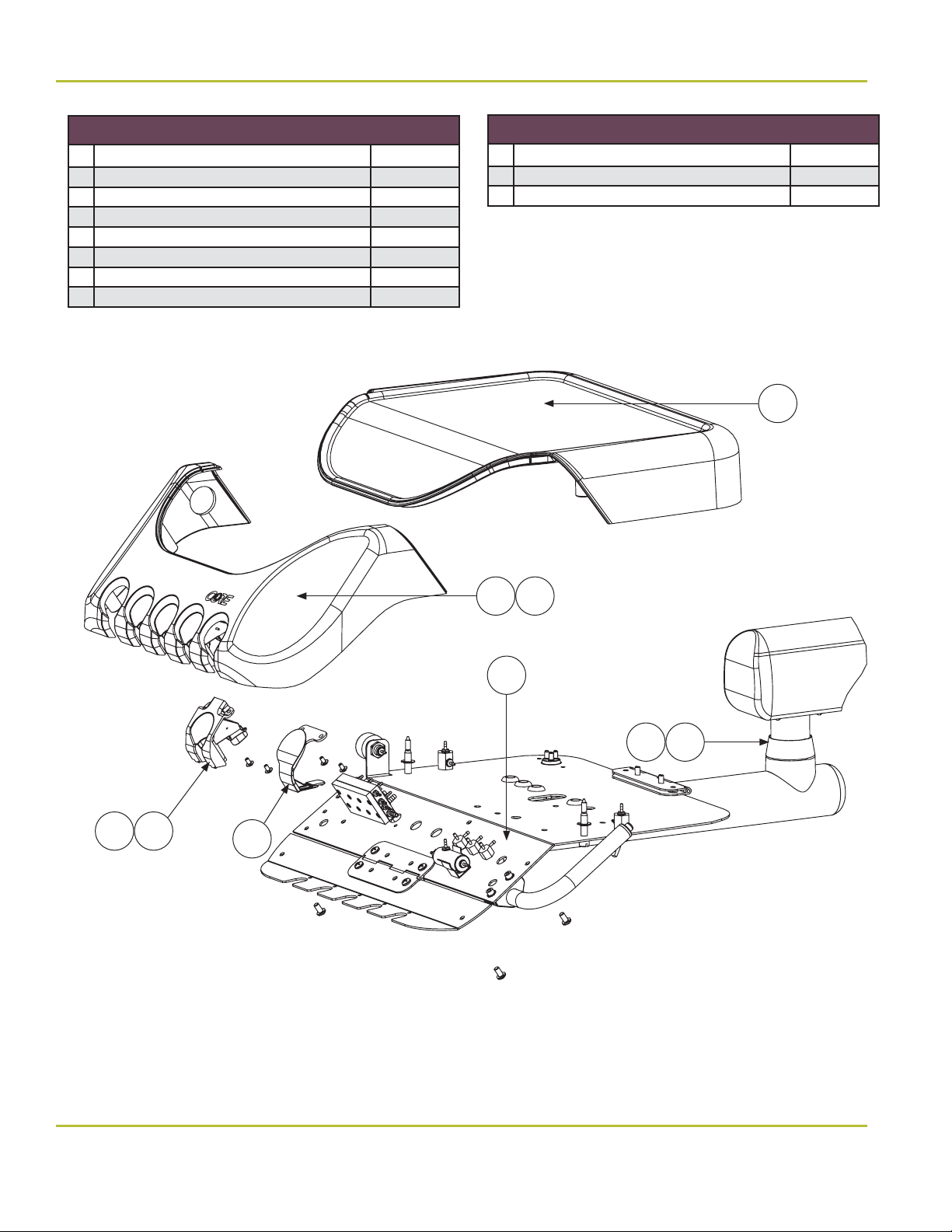
CORE Delivery Head
# Part/Kit Name Part/Kit No.
1 CORE Rigid Arm Cap 3802-553
2 CORE Flex Arm Cap 3802-554
3 CORE Flex Arm Cover 3802-555
4 Master ON/OFF Toggle 3802-063
5 Flush Toggle 3802-064
6 Air Pressure Gauge 3801-695
7 Repair Kit for Control Block 3802-386
8 Water Retraction Valve 3800-417
9 Brake Handle and Valve 3802-249
10 Lid Screw 3802-387
11 CORE Unit Oil Collector 3802-550
3
1
4
6
11
5
7
10
9
8
www.DentalEZ.com
PN: 2717-267C
47
47
866-DTE-INFO
Section VIII Parts Lists/Diagrams
CORETM Magellan Unit
CORE Delivery Head (Continued)
# Part/Kit Name Part/Kit No.
12 CORE HP Holder w/o Valve 3802-545
13 CORE HP Holder w/ Valve 3802-546
14 CORE HP Blank 3802-547
15 CORE Unit Cover 3802-548
16 CORE Unit Water Adjustment Valve 3802-549
17 CORE Head to Flex Arm Cap 3802-551
18 CORE Head to Flex Arm Key 3802-552
Touch Pads
# Part/Kit Name Part/Kit No.
19 CORE Chair 3802-573
20 NuSimplicity Chair 3802-580
15
19 20
16
1817
1312
14
www.DentalEZ.com
PN: 2717-267C
866-DTE-INFO
48

Section VIII Parts Lists/Diagrams
DentalEZ
®
Equipment
Clean Water System
# Part/Kit Name Part/Kit No.
1 Water Bottle 3802-349
2* City/Bottle Toggle 3802-116
3 Bottle ON/OFF Toggle 3802-117
4 Regulator Assembly 3802-118
5 Water Bottle Gasket 3802-342
Water Bottle, Complete Assembly 3625-763
*Optional Equipment
3
4
5
Foot Control
# Part/Kit Name Part/Kit No.
6 Drive Air Repair Kit 3802-417
7 Wet/Dry Toggle Valve 3802-418
8 Chip Air Valve 3802-419
9 Shuttle Valve Kit 3801-585
10 Kit, Ring - Foot Control XC 3802-484
Foot Control Complete 3625-498
7
8
6
1
10
9
www.DentalEZ.com
PN: 2717-267C
49
49
866-DTE-INFO

Section VIII Parts Lists/Diagrams
CORETM Magellan Unit
Air/Water Syringe
# Part/Kit Name Part/Kit No.
1 Cartridges 3802-203
2 Syringe Tip Kit 3802-205
3 O-Rings (Complete Set) 3658-420
HVE Nozzle
# Part/Kit Name Part/Kit No.
HVE Repair Kit 3802-154
Full Replacement Parts Kit 3801-927
1
2
3
Saliva Ejector Nozzle
# Part/Kit Name Part/Kit No.
SE Repair Kit 3802-153
Full Replacement Parts Kit 3801-926
www.DentalEZ.com
PN: 2717-267C
DentalEZ Parts Online
To order parts online, visit www.dentalezparts.com or
scan QR code with smartphone.
866-DTE-INFO
50

EMC Information
DentalEZ
®
Equipment
WARNING
• Use only replacement cables listed in Parts section. Other cables and accessories may negatively a ect
EMC performance.
• When the CORE Magellan Unit is used adjacent to other equipment, observe the unit to verify normal
operation.
Guidance and Manufacturer’s Declaration – Electromagnetic Emissions
The CORE Magellan Unit is intended for use in the electromagnetic environment speci ed below. The customer or the user of the CORE Magellan Unit
should assure that it is used in such an environment.
Emissions Test Compliance Electromagnetic Environment Guidance
RF Emissions CISPR 11 Group 1
RF Emissions CISPR 11 Class A
Harmonic Emissions
IEC 61000-3-2
Voltage Fluctuations/Flicker
Emissions
IEC 61000-3-3
Class A Not applicable
Class A Not applicable
The CORE Magellan Unit uses RF energy only for its internal function; therefore, its RF emissions are
very low and are not likely to cause any interference in nearby electronic equipment.
The CORE Magellan Unit is suitable for use in all establishments, other than domestic establishments
and those directly connected to the public low-voltage power supply network that supplies buildings
used for domestic purposes.
Guidance and Manufacturer’s Declaration – Electromagnetic Immunity
The CORE Magellan Unit is intended for use in the electromagnetic environment speci ed below. The customer or the end user of the CORE Magellan Unit
should assure that it is used in such an environment.
Immunity Test IEC 60601 Test Level Compliance Level Electromagnetic Environment Guidance
Electrostatic Discharge (ESD)
IEC 61000-4-2
Electrical Fast Transient/
Burst IEC 61000-4-4
Surge IEC 61000-4-5
Voltage Dips, Short
Interruptions and Voltage
Variations on Power Supply
Input Lines IEC 61000-4-11
Power Frequency (50/60 Hz)
Magnetic Field IEC 61000-4-8
NOTE: Ut is the AC mains voltage prior to application of the test level.
±6 kV contact
±8 kV air
±2 kV for power supply lines
±1 kV for input/output lines
±1 kV di erential mode
±2 kV common mode
<5% Ut (>95% dip in Ut)
for 0.5 cycle
40% Ut (60% dip in Ut)
for 5 cycles
70% Ut (30% dip in Ut)
for 25 cycles
<5% Ut (>95% dip in Ut)
for 5 sec
3 A/m 3 A/m
± 6 kV contact
± 8 kV air
± 2 kV for power supply lines
±1 kV for input/output lines
±1 kV di erential mode
±2 kV common mode
<5% Ut (>95% dip in Ut)
for 0.5 cycle
40% Ut (60% dip in Ut)
for 5 cycles
70% Ut (30% dip in Ut)
for 25 cycles
<5% Ut (>95% dip in Ut)
for 5 sec
Floors should be wood, concrete or ceramic tile.
If oors are covered with synthetic material, the
relative humidity should be at least 30%.
Mains power quality should be that of a typical
commercial or hospital environment.
Mains power quality should be that of a typical
commercial or hospital environment.
Mains power quality should be that of a typical
commercial or hospital environment. If the user of
the CORE Magellan Unit requires continued
operation during power mains interruptions, it is
recommended that the CORE Magellan Unit be
powered from an uninterruptible power supply or a
battery.
Power frequency magnetic elds should be at
levels characteristic of a typical location in a typical
commercial or hospital environment.
www.DentalEZ.com
PN: 2717-267C
51
51
866-DTE-INFO

EMC Information
CORETM Magellan Unit
Guidance and Manufacturer’s Declaration – Electromagnetic Emissions
The CORE Magellan Unit is intended for use in the electromagnetic environment speci ed below. The customer or the user of the CORE Magellan Unit
should assure that it is used in such an environment.
Immunity Test
Radiated RF
IEC 61000-4-3
Conducted RF
IEC 61000-4-6
NOTE 1: At 80 MHz and 800 MHz, the higher frequency range applies.
NOTE 2: These guidelines may not apply in all situations. Electromagnetic propagation is a ected by absorption and re ection from structures, objects and people.
a. Field strengths from xed transmitters, such as base stations for radio (cellular/cordless) telephones and land mobile radios, amateur radio, AM
and FM radio broadcast and TV broadcast cannot be predicted theoretically with accuracy. To assess the electromagnetic environment due to xed
RF transmitters, an electromagnetic site survey should be considered. If the measured eld strength in the location in which the CORE Magellan
Unit is used exceeds the applicable RF compliance level above, the CORE Magellan Unit should be observed to verify normal operation. If abnormal
performance is observed, additional measures may be necessary, such as reorienting or relocating the CORE Magellan Unit.
b. Over the frequency range 150 kHz to 80 MHz, eld strengths should be less than 3 V/m.
IEC 60601 Test
Level
3 V/m
80MHz to 2.5 GHz
150 kHz to 80 MHz
Compliance
Level
3 V/m
3 Vrms
Electromagnetic Environment Guidance
Portable and mobile RF communications equipment should be used no closer to any part of the
equipment, including cables, than the recommended separation distance calculated from the
equation applicable to the frequency of the transmitter.
d = 1.7 √P 80 MHz to 800 MHz
d = 2.3 √P 800 MHz to 2.5 GHz
d = [3.5/V1] √P
where P is the maximum output power rating of the transmitter in watts (W) according to the
transmitter manufacturer and d is the recommended separation distance in meters (m).
Field strengths from xed RF transmitters, as determined by an electromagnetic site survey,
should be less than the compliance level in each frequency range.
Interference may occur in the vicinity of equipment marked with the following symbol:
b
a
Recommended Separation Distance Between Portable and Mobile
RF Communications Equipment and the Model @ 3Vrms
The CORE Magellan Unit is intended for use in an electromagnetic environment in which radiated RF disturbances are controlled. The customer or
the user of the CORE Magellan Unit can help prevent electromagnetic interference by maintaining a minimum distance between portable and mobile
RF communications equipment (transmitters) and the CORE Magellan Unit as recommended below, according to the maximum output power of the
communications equipment.
Separation distance according to frequency of transmitter m
Rated maximum output power
of transmitter W
0.01 0.12 0.12 0.23
0.1 0.34 0.34 0.74
11.71.72.3
10 3.7 3.7 7.4
100 11.7 11.7 23.3
For transmitters rated at a maximum output power not listed above, the recommended separation distance d in meters (m) can be estimated using the
equation applicable to the frequency of the transmitter, where P is the maximum output rating of the transmitter in watts (W) according to the transmitter
manufacturer.
NOTE 1: At 80 MHz and 800 MHz, the separation distance for the higher frequency range applies.
NOTE 2: These guidelines may not apply in all situations. Electromagnetic propagation is a ected by absorption and re ection from structures, objects
and people.
150 kHz to 80 MHz 80 MHz to 800 MHz 800 MHz to 2.5 GHz
d
3.5
v
3.5
P
1
d
E
P
1
d
7
E
P
1
www.DentalEZ.com
PN: 2717-267C
866-DTE-INFO
52

Limited Warranty
DentalEZ
®
Equipment
CORETM Magellan Unit
DentalEZ and its employees are proud of the products we provide in the dental community. We stand behind these products
with a warranty against defects in material and workmanship as provided below.
In the event you experience di iculty with the application or operation of any of our products, please contact our Technical
Service Department at our expense at 866-DTE-INFO (866-383-4636).
If we cannot resolve the issue by telephone, we will arrange for a representative to contact you or suggest that the product
be repaired by a dealer service technician.
If product repair or return is required, we will provide you with a Return Authorization number and shipping instructions to
return the product to the proper facility. If the product is under warranty, we will ask you to provide proof of purchase, such
as a copy of your invoice. Please be sure to include the Return Authorization number on the package you are returning.
Products returned without a Return Authorization number cannot be repaired.
Freight costs for product returns are the responsibility of the customer. Products under warranty will be repaired or replaced
at our sole discretion and returned at our expense. Products outside the warranty limits will be repaired and returned with
costs invoiced to the customer. We are not responsible for shipping damages. We will, however, help you le a claim with the
freight carrier. Written repair estimates are available.
DentalEZ warrants the CORE Magellan Unit to be free of defects in material and workmanship, under normal usage, under
the following terms:
The following items are covered under this limited warranty for a period of ve (5) years from the date of installation*, with
the exception of the following items which are covered under this warranty for a period of one (1) year from the date of
installation*:
• Tubings and Fittings
• Wiring
• Syringe
Please note the following additional terms of our warranty and return policy:
• Warranties cover manufacturing defects only and do not cover defects resulting from abuse, improper handling,
cleaning, care or maintenance, normal wear and tear or non-observance of operating, maintenance or installation
instructions. Failure to use authorized parts or an authorized repair facility voids this warranty.
• Liability is limited to repair or replacement of the defective product at our sole discretion. All other liabilities, in
particular liability for damages, including, without limitation, consequential or incidental damages are excluded.
• THIS WARRANTY IS IN LIEU OF ALL OTHER WARRANTIES, EXPRESSED OR IMPLIED, INCLUDING ANY IMPLIED WARRANTIES
OF MERCHANTABILITY OR FITNESS FOR A PARTICULAR PURPOSE. NO EMPLOYEE, REPRESENTATIVE OR DEALER IS
AUTHORIZED TO CHANGE THIS WARRANTY IN ANY WAY OR TO GRANT ANY OTHER WARRANTY.
WARRANTY REPAIRS: Parts repaired or replaced on a product that is in warranty will be warranted for the duration of that
product’s original warranty.
NON-WARRANTY REPAIRS: The warranty on parts either repaired or replaced on an out-of-warranty product will cover the
repaired part only and will be for the time frame of a new parts warranty period.
PRODUCT RETURN: Opened products or product returns more than a year old cannot be returned for credit. There will be a 15%
($25.00 minimum) restocking charge on all items authorized for return.
*Provided conditions de ned in the Installation, Operation and Care Manual are met.
DentalEZ is a registered trademark of DentalEZ, Inc. CORE and NuSimplicity are trademarks of DentalEZ, Inc. SlugBuster is a
trademark of RAMVAC Dental Products, Inc.
© 2019 DentalEZ Alabama, Inc.
• Instrument Holder Insert
• Handpiece Tubings
• Cup Fill and Bowl Rinse Spouts
• High-Volume Evacuator Valves and
Saliva Ejector Valves
www.DentalEZ.com
PN: 2717-267C
53
53
866-DTE-INFO

© DentalEZ® Alabama, Inc.
Printed in USA
2500 Highway 31 South
Bay Minette, Alabama 36507
866-DTE-INFO
www.dentalez.com
PN: 2717-267C
April, 2019
 Loading...