

Page 1
A
0
E
Barcode Handy Terminal
BHT-70
-C
PI Reference Manual
Page 2

Copyright © DENSO WAVE INCORPORATED, 2007
All rights reserved. No part of this publication may be reproduced in any form or by any means without
permission in writing from the publisher.
Specifications are subject to change without prior notice.
All products and company names mentioned in this manual are trademarks or registered trademarks of their
respective holders.
Page 3

Contents
Chapter 1. Software Requirements for the BHT-700 ...................................................................................... 1
1.1. Operating System (OS) on the BHT-700.......................................................................................... 1
1.2. Application Development Software on the PC.................................................................................. 1
1.2.1. Application Development Tool ...................................................................................................... 1
1.2.2. Software Development Kit ............................................................................................................ 1
Chapter 2. Application Development Environment ......................................................................................... 2
2.1. Required Hardware (PC to be used for application development) ................................................... 2
2.2. Required Software ........................................................................................................................... 2
2.3. Installation ........................................................................................................................................ 2
Chapter 3. Output to the LCD Screen............................................................................................................. 3
3.1. Screen Fonts.................................................................................................................................... 3
3.2. Screen Rotation ............................................................................................................................... 3
3.2.1. Setting the Screen Rotation Control Key ...................................................................................... 3
3.3. Setting the Screen Rotation Angle ................................................................................................... 4
Chapter 4. Backlight Control........................................................................................................................... 5
4.1. Outline.............................................................................................................................................. 5
4.2. Setting the Backlight Function On/Off Key ....................................................................................... 5
4.3. Setting the Backlight Illumination Time............................................................................................. 6
4.4. Setting the Backlight Brightness and Power Saving Mode............................................................... 6
4.5. Controlling the Backlight with the Backlight Control Key .................................................................. 7
4.6. Controlling the Backlight with the Backlight Control Function........................................................... 8
4.7. Key Backlight ................................................................................................................................... 9
Chapter 5. Beeper and Vibrator Control ....................................................................................................... 10
5.1. Outline............................................................................................................................................ 10
5.2. Setting the Beeper/Vibrator ............................................................................................................ 11
5.3. Starting/Stopping the Beeper/Vibrator............................................................................................ 12
5.4. Priority Orders between Events that Activate the Beeper/Vibrator ................................................. 12
5.5. Beeper Volume Patterns ................................................................................................................ 12
Chapter 6. Keys and Trigger Switch Control ................................................................................................ 13
6.1. Outline............................................................................................................................................ 13
6.2. Setting the Keys and Trigger Switch .............................................................................................. 14
6.3. Shift Key Operation Mode .............................................................................................................. 15
6.4. Magic Key Control.......................................................................................................................... 15
6.5. Assigning a User-Defined Key Code to the Magic Keys ................................................................ 16
6.5.1. Assignment Method .................................................................................................................... 16
6.5.2. User-Defined Code Settings File (MKeyDef.txt).......................................................................... 16
6.6. Key Input Modes ............................................................................................................................ 17
6.6.1. Numeric Entry Mode ................................................................................................................... 17
6.6.2. Alphabet Entry Mode 1 (27 key pad) .......................................................................................... 17
6.7. Function Mode ............................................................................................................................... 20
6.8. Key Clicks ...................................................................................................................................... 20
6.9. Acquisition of Keypad Type............................................................................................................ 20
6.10. Auto Repeat Function .................................................................................................................... 21
Chapter 7. LCD Status Indication ................................................................................................................. 22
7.1. Outline............................................................................................................................................ 22
7.2. Setting the LCD Status Indication .................................................................................................. 23
Chapter 8. Power Management.................................................................................................................... 24
8.1. Outline............................................................................................................................................ 24
8.2. Standby .......................................................................................................................................... 25
8.2.1. Switching to the Standby State ...................................................................................................... 25
8.2.2. Standby Transition Prohibited Events ............................................................................................ 25
8.2.3. Setting the Standby Transition Timeout ......................................................................................... 25
8.3. Suspend ......................................................................................................................................... 26
8.3.1. Setting the Standby Transition Timeout ......................................................................................... 26
8.3.2. Suspend Transition Prohibited Events ........................................................................................... 26
8.3.3. Setting the Auto Power-off Timeout ............................................................................................... 26
8.3.4. Setting the Effective Held-down Time of the Power Key for Switching to the Suspend State ........ 26
Chapter 9. Battery State ............................................................................................................................... 27
Page 4

9.1. Outline............................................................................................................................................ 27
9.2. Battery Voltage Acquisition ............................................................................................................ 27
9.3. Battery Voltage Icon....................................................................................................................... 27
9.4. Battery Voltage Warning ................................................................................................................ 27
Chapter 10. LED ......................................................................................................................................... 28
10.1. Outline............................................................................................................................................ 28
10.2. LED Control.................................................................................................................................... 28
10.2.1. Display LED ................................................................................................................................. 28
10.2.2. Charge LED ................................................................................................................................. 28
Chapter 11. Data Communication............................................................................................................... 29
11.1. Outline............................................................................................................................................ 29
11.2. Programming for Data Communication .......................................................................................... 29
11.3. Assigning Port Number .................................................................................................................. 29
11.4. ActiveSync ..................................................................................................................................... 30
11.4.1. Establishing an ActiveSync Connection ....................................................................................... 30
11.4.2. ActiveSync Auto Connection Setting Method............................................................................... 30
Chapter 12. Wireless Communication......................................................................................................... 31
12.1. Outline............................................................................................................................................ 31
12.1.1. Spread Spectrum Communications Method ............................................................................ 31
12.1.2. Configuration of Spread Spectrum System ............................................................................. 31
12.2. Programming for Wireless Communication .................................................................................... 32
12.2.1. Wireless Communication Parameters ..................................................................................... 33
12.2.2. Opening and Closing the Wireless Communications Device................................................... 36
12.2.3. Checking Synchronization with the Access Point .................................................................... 37
Chapter 13. Barcode Reading..................................................................................................................... 38
13.1. Outline............................................................................................................................................ 38
13.1.1. Enable Reading....................................................................................................................... 38
13.1.2. Specify Options in the BHT_EnableBar Function .................................................................... 40
13.1.3. Barcode Buffer ........................................................................................................................ 41
13.2. Programming.................................................................................................................................. 42
13.2.1. Code Mark............................................................................................................................... 42
13.2.2. Multiple Code Reading ............................................................................................................ 42
13.2.3. Read Mode of the Trigger Switch ............................................................................................ 42
13.2.4. Generating a Check Digit of Barcode Data.............................................................................. 42
13.2.5. Controlling the Indicator LED and Beeper/Vibrator as a Confirmation of Successful Reading 43
13.2.6. Reading Split QR Codes (Only for BHT-700Q) ....................................................................... 43
13.3. Barcode Reading Using the Virtual COM Port ............................................................................... 44
13.3.1. Outline..................................................................................................................................... 44
13.3.2. Programming........................................................................................................................... 44
13.3.3. How to Use.............................................................................................................................. 44
Chapter 14. Updating OS............................................................................................................................ 45
Chapter 15. System Functions.................................................................................................................... 46
15.1. If a System Parameter Value is DWORD ....................................................................................... 47
15.2. If a System Parameter Value is a Character String........................................................................ 49
15.3. System Parameter Values That Can be Set/Obtained ................................................................... 51
15.4. Device Information Acquisition ....................................................................................................... 57
Chapter 16. Device Control Functions ........................................................................................................ 58
16.1. Barcode API ................................................................................................................................... 60
16.2. Backlight API................................................................................................................................ 101
16.3. Battery API ................................................................................................................................... 103
16.4. LED API ....................................................................................................................................... 105
16.5. Beeper/Vibrator API ..................................................................................................................... 110
16.6. Wireless Communication API....................................................................................................... 115
16.7. OS Updating API.......................................................................................................................... 131
16.8. Bluetooth API ............................................................................................................................... 132
16.9. Other APIs ........................................................................................................................................ 135
Chapter 17. Programming Using OCX (OLE Customer Control) .............................................................. 141
17.1. System Requirements.................................................................................................................. 141
17.2. Installation .................................................................................................................................... 141
17.3. Using OCX ................................................................................................................................... 141
17.4. Scanner Control ........................................................................................................................... 144
Page 5

17.4.1. Properties .............................................................................................................................. 144
17.4.2. Methods................................................................................................................................. 145
17.4.3. Event Callback Function........................................................................................................ 148
17.4.4. Error Codes ........................................................................................................................... 149
17.4.5. Coding Sample...................................................................................................................... 149
17.5. File Transfer Control .................................................................................................................... 150
17.5.1. Properties .............................................................................................................................. 150
17.5.2. Methods................................................................................................................................. 151
17.5.3. Event Callback Functions ...................................................................................................... 157
17.5.4. Coding Sample...................................................................................................................... 159
Appendix A. Keyboard Arrangement, Virtual Key Codes and Character Codes........................................ 160
A.1. 27-key pad ................................................................................................................................... 160
A.1.1. Keyborard Arrangement............................................................................................................ 160
A.1.2. Virtual Key Codes and Character Codes.................................................................................. 161
A.1.3. Character Codes in Alphabet Entry Mode................................................................................. 163
A.2. 42-key pad ................................................................................................................................... 164
A.2.1. Keyborard Arrangement............................................................................................................ 164
A.2.2. Virtual Key Codes and Character Codes.................................................................................. 166
Appendix B. Differences between Older Unit............................................................................................. 169
Page 6

Chapter 1. Software Requirements for the BHT-700
1.1. Operating System (OS) on the BHT-700
The OS running on the BHT-700 is Microsoft Windows CE 5.0.
1.2. Application Development Software on the PC
1.2.1. Application Development Tool
The application development tool for the BHT-700 is Microsoft eMbedded Visual C++ 4.0 (Service Pack
4)
1.2.2. Software Development Kit
The BHT-700 Software Development Kit provides the application development environment for Windows
CE set up on the BHT-700. It includes the following libraries:
(1) Help files
(2) Windows-CE standard header files
(3) Windows-CE standard library files
(4) BHT-dedicated header file : BHTLIB.h
• Includes statements for declaring BHT-dedicated APIs prototypes and macro definition of
constants.
• To use the BHT-dedicated APIs, the BHTLIB.h should be included.
(5) BHT-dedicated library : BHTLIB.lib
• Includes BHT-dedicated barcode reading functions and device driver management functions.
• To use the BHT-dedicated APIs, the BHTLIB.lib should be linked.
(6) BHT-dedicated OCX files : Scanner700.ocx (for BHT-700B), Scanner700Q.ocx (for BHT-700Q),
FileTransfer700.ocx, and FileTransferPC.ocx (for PC)
• Include BHT-dedicated barcode scanning functions and file transfer functions.
• To use the BHT-dedicated OCX, Scanner700.ocx, Scanner700Q.ocx, and FileTransfer700.ocx
should be linked.
1
Page 7

Chapter 2. Application Development Environment
2.1. Required Hardware (PC to be used for application development)
Item Specification
OS Microsoft Windows 2000 Professional with Service Pack 2 or higher,
or Microsoft Windows 2000 Server with Service Pack 2 or higher,
or Microsoft Windows XP Professional or higher.
PC With a Pentium-II class processor, 450 MHz or faster
Memory
HDD 200 MB or more hard disk space
Display VGA or higher-resolution monitor.
2.2. Required Software
Application development tool: Microsoft eMbedded Visual C++ 4.0 (SP4)
You can download Microsoft eMbedded Visual C++ 4.0 and Service Pack 4 from the Microsoft Web site:
(Microsoft eMbedded Visual C++ 4.0)
http://www.microsoft.com/downloads/details.aspx?FamilyID=1dacdb3d-50d1-41b2-a107fa75ae960856&DisplayLang=en
(Service Pack 4)
http://www.microsoft.com/downloads/details.aspx?FamilyID=4a4ed1f4-91d3-4dbe-986ea812984318e5&displaylang=en
APIs available for eMbedded Visual C++ are:
(1) Win32API
(2) Microsoft Foundation Class (MFC)
(3) Dedicated APIs (for device control or data entry from the BHT)
Software development kit: BHT700_XXX_SDK.msi
This should be embedded into Microsoft eMbedded Visual C++ 4.0 for use.
2.3. Installation
The Microsoft eMbedded Visual C++ 4.0 and BHT-700 software development kit should be installed to
an application development PC in this order. To install the development kit, run the BHT700_XXX.msi in
the BHT-700 Software Development Kit CD.
For Microsoft Windows 2000 Professional or Microsoft Windows XP Professional:
96 MB or more (128 MB or more recommended)
For Microsoft Windows 2000 Server :
192 MB or more (256 MB or more recommended)
A Super VGA (800 x 600 or larger) monitor is recommended.
2
Page 8

Chapter 3. Output to the LCD Screen
3.1. Screen Fonts
The BHT-700 has the following integrated screen fonts:
(1) Arial (ttf)
(2) Courier New (ttf)
(3) Tahoma (ttf)
(4) Time New Roman (ttf)
(5) Wingding (ttf)
If no screen font is specified, Tahoma applies automatically.
3.2. Screen Rotation
The screen can be rotated using either of the following methods.
(1) By pressing the screen rotation control key.
(2) By using the system setting function (BHT_SetSysSettingDW).
3.2.1. Setting the Screen Rotation Control Key
The screen rotation control key can be set using the
BHT_SetSysSettingDW (BHT_DISP_ROTATION_KEY,…) function.
Furthermore, the setting can be obtained using the
BHT_GetSysSettingDW (BHT_DISP_ROTATION_KEY,…) function.
The relationship between the settable screen rotation control keys and settings is outlined in the following
table.
Screen Rotation Control Key Set value Screen Rotation Control Key Set value
[M1] 0x00000201 [SF]+[M1] 0x00010201
[M2] 0x00000202 [SF]+[M2] 0x00010202
[M3] 0x00000203 [SF]+[M3] 0x00010203
3
Page 9

3.3. Setting the Screen Rotation Angle
The settable rotation angles are 0°, 90°, 180°, and 270°. The direction is anti-clockwise.
The screen rotation angle can be set and read using the
BHT_SetSysSettingDW (DWORD dwCtrlCode,DWORD dwSysParam) and
BHT_GetSysSettingDW (DWORD dwCtrlCode,DWORD *pdwSysParam) functions, respectively.
Parameter Type R/W
Screen
rotation
angle
DW R/W
Control Code
(dwCtrlCode)
BHT_DISP
_ROTATION
Parameter Value
(dwSysParam)
DISP_ROTATION_0
: 0°
DISP_ROTATION_90
: 90°
DISP_ROTATION_180
: 180°
DISP_ROTATION_270
: 270°
Default
DISP_ROTATION_0
Validation
Timing
Immediately
after setting
4
Page 10

Chapter 4. Backlight Control
4.1. Outline
The backlight illumination and power saving modes can be controlled using either of the following
methods.
(1) The backlight can be controlled by pressing the backlight control key.
(2) The backlight can be controlled using the backlight control function (BHT_SetBltStatus).
The following backlight related setting items are also available.
(1) Backlight control key
(2) Backlight illumination time
(3) Backlight brightness
(4) Backlight power saving mode
Furthermore, the BHT-700 keypad is also equipped with a backlight (hereafter referred to as key
backlight) for which the following settings can be made.
(1) Illumination device (when BHT_SetBltStatus is called)
(2) Key backlight illumination trigger
4.2. Setting the Backlight Function On/Off Key
You can assign the backlight function on/off key to other keys by the BHT_SetSysSettingDW
(BHT_BACKLIGHT_KEY...) function or by assigning the backlight control function to the magic key.The
table below lists the relationship between the keys that act as a backlight function on/off key and the set
values in the BHT_SetSysSettingDW (BHT_BACKLIGHT_KEY...) function.
If no key is specified as a backlight function on/off key, the combination of the SF key and M3 key works
as a backlight function on/off key by default.
Backlight control key Set value Backlight control key Set value
[M1] 0x00000201 [SF]+[M1] 0x00010201
[M2] 0x00000202 [SF]+[M2] 0x00010202
[M3] 0x00000203 [SF]+[M3] 0x00010203
[Ex]
Execute function BHT_SetSysSettingDW (BHT_BACKLIGHT_KEY, 0x00010201) when assigning a
simultaneous combination of the [SF] and [M1] keys to the backlight control key.
5
Page 11

4.3. Setting the Backlight Illumination Time
The backlight illumination time is set and read using the
BHT_SetSysSettingDW (DWORD dwCtrlCode,DWORD dwSysParam) and
BHT_GetSysSettingDW (DWORD dwCtrlCode,DWORD *pdwSysParam) functions.
Parameter Type R/W
Illumination time
DW R/W
when powered
by battery (sec.)
Illumination time
DW R/W
when placed on
CU (sec.)
Control Code
(dwCtrlCode)
BHT_BACKLIGHT
_BATT_TIME
BHT_BACKLIGHT
_AC_TIME
Parameter Value
(dwSysParam)
0 - 255
0: Backlight OFF
255: Continuously ON
0 - 255
0: Backlight OFF
255: Continuously ON
4.4. Setting the Backlight Brightness and Power Saving Mode
The backlight brightness and power saving mode are set and read using the
BHT_SetSysSettingDW (DWORD dwCtrlCode,DWORD dwSysParam) and
BHT_GetSysSettingDW (DWORD dwCtrlCode,DWORD *pdwSysParam) functions.
Parameter Type R/W
Backlight
brightness
Backlight power
saving mode
DW R/W
DW R/W
Control Code
(dwCtrlCode)
BHT_BACKLIGHT
_BRIGHTNESS
BHT_BACKLIGHT
_POWERSAVE
Parameter Value
(dwSysParam)
0: OFF
1: Dark
2: Bright (low)
3: Bright (high)
0: OFF
1: Dim
Default Validation Timing
When backlight
3
illumination timer is
next reset
60
Default Validation Timing
3
1
When backlight
illumination timer is
next reset
When the backlight is
next turned ON
When backlight
illumination status is
set to power saving
mode first after
setting
6
Page 12
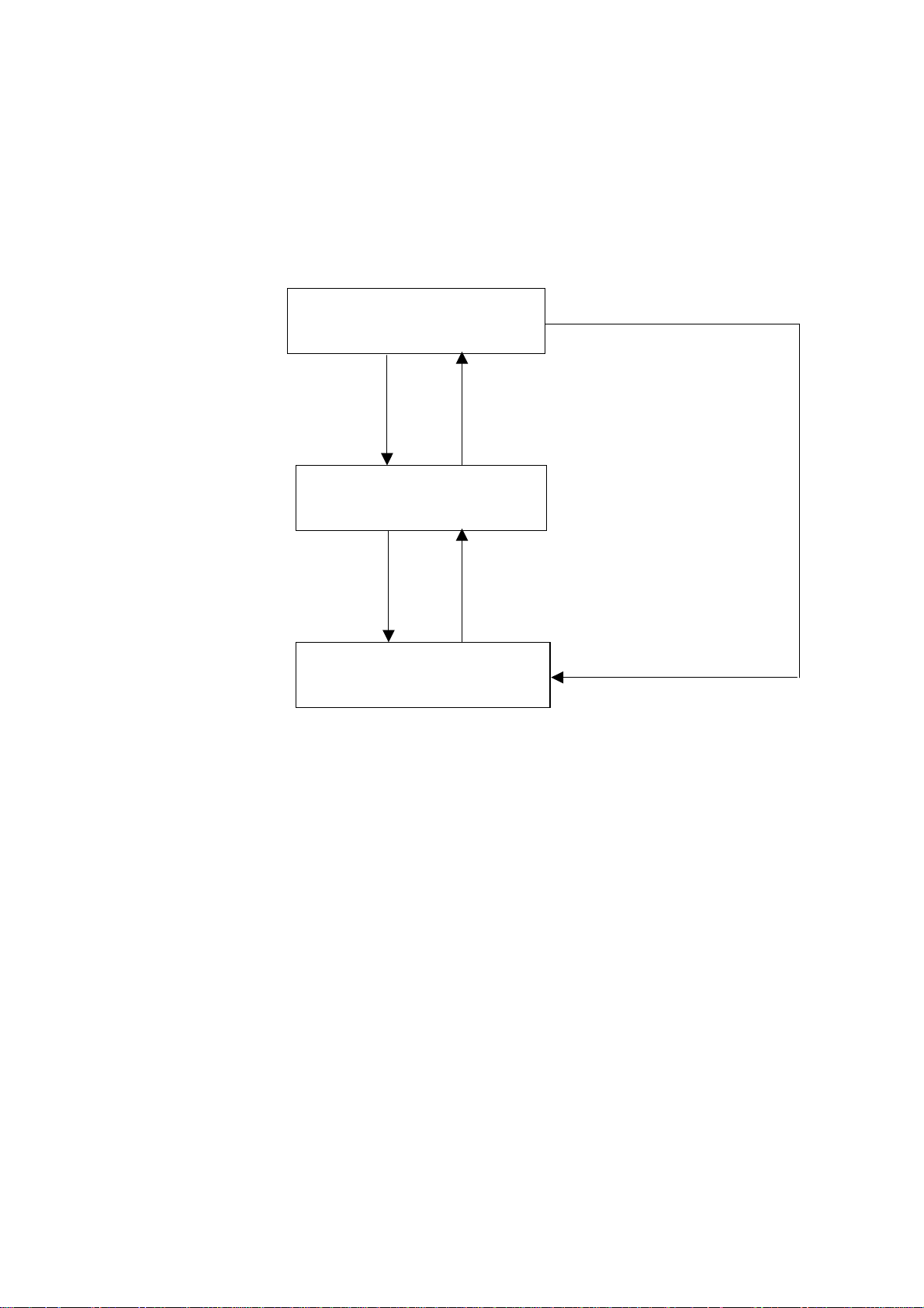
4.5. Controlling the Backlight with the Backlight Control Key
The backlight function can be enabled/disabled by pressing the backlight function control key (Default:
Hold down [SF] key and press [M3].).
The illumination time is specified using the BHT_SetSysSettingDW
(BHT_BACKLIGHT_BATT_TIME/BHT_BACKLIGHT_AC_TIME, …) function. The default value is 3
seconds when powered by the battery, and 60 seconds when placed on the CU. Backlight control is
performed as shown in the flow diagram below.
(1) Backlight power saving mode
(backlight function ON)
Press a key other (*3) than the backlight
control key. (*1)
Or alternatively tap the touch panel. (*4)
No key other than the backlight control key (*1) is
pressed and the touch panel is not tapped prior to
the backlight illumination time (*2) elapsing.
(2) Backlight ON
Press the backlight control key. (*1)
Press the backlight contr
(*1)
Default:
Setting is possible using the BHT_SetSysSettingDW (BHT_BACKLIGHT_KEY,…
(*2)
The backlight illumination time is set using the BHT_SetSysSettingDW (BHT_BACKLIGHT_BATT_TIME/
BHT_BACKLIGHT_AC_TIME,…
backlight control key is pressed, or if the touch panel is not tapped within this time.
This time is measured from the point all keys are released or the touch panel is last pressed.
(*3)
If key-press has not been set for the key backlight illumination trigger, the key backlight will not illuminate
even if a key is pressed. If, however, the key backlight is already illuminated beforehand, it will not turn
OFF by pressing a key.
(*4)
If touch panel tap has not been set for the key backlight illumination trigger, the key backlight will not
illuminate even if the touch panel is tapped. If, however, the key backlight is already illuminated
beforehand, it will not turn OFF by tapping the touch panel.
(*5)
Cold booting is performed from the status at (1) above.
However, cold booting is performed from the status at (1) when the registry is saved with the status at (1)
or (2), and is performed from the status at (3) when the registry is saved with the status at (3).
(*6)
When performing warm booting or when resuming from the suspend status, the process is performed from
(1) if the status prior to warm boot/suspend is (1) or (2), and is performed from (3) if the status prior to
warm boot/suspend is (3).
Hold down [SF] key and press [M3].
(3) Backlight power saving mode
(backlight function OFF)
) function. Power saving mode is enabled if no key other than the
Press the backlight control key. (*1)
) function.
7
Page 13
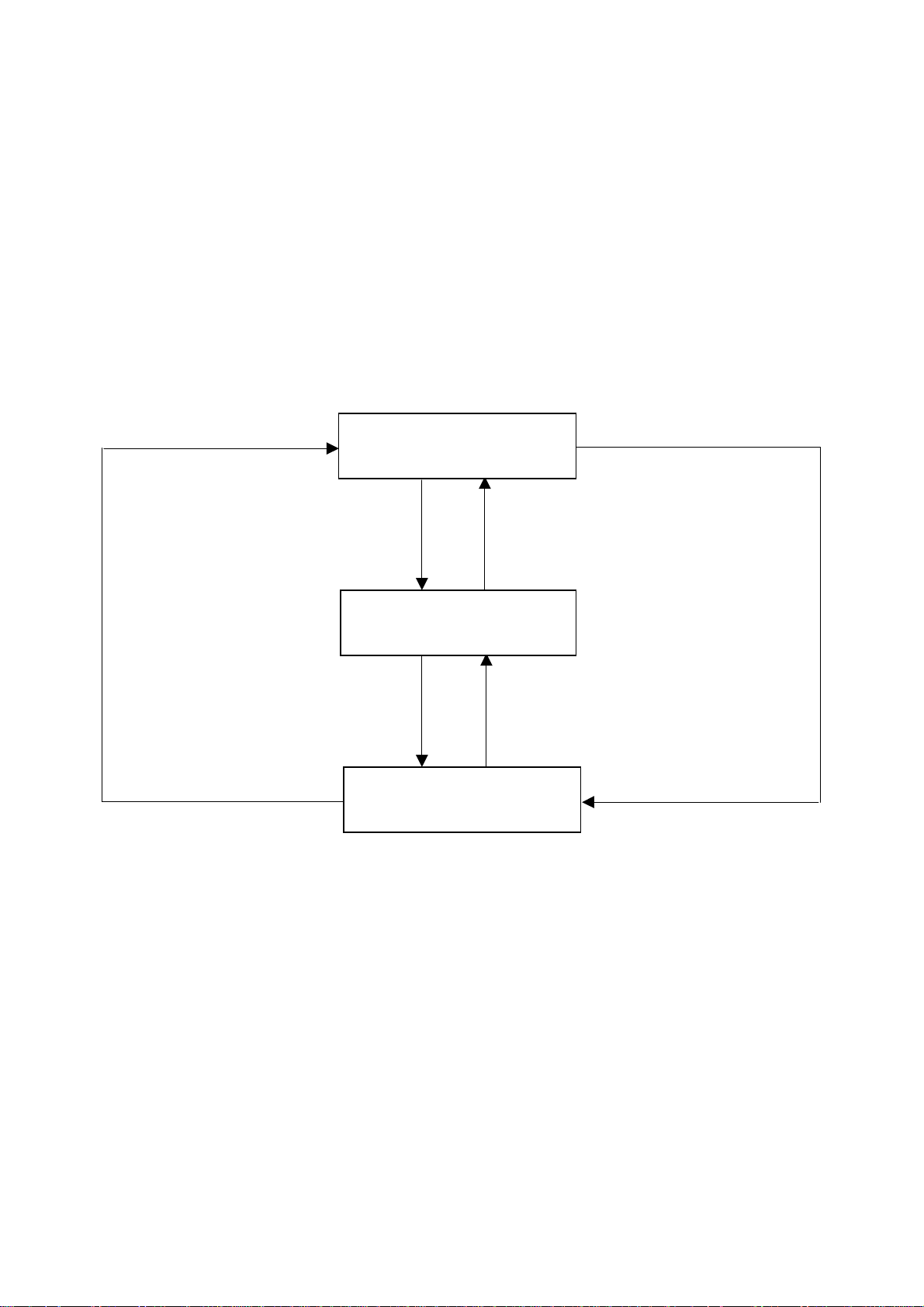
4.6. Controlling the Backlight with the Backlight Control Function
The backlight function can be controlled using the BHT_SetBltStatus function.
The BHT_SetBltStatus (BHT_BL_ENABLE_ON) function is used to enable the backlight function and turn
the backlight ON.
The backlight power saving mode is enabled if no keys are pressed, or the touch panel tapped from the
point the backlight is turned ON using the BHT_SetBltStatus (BHT_BL_ENABLE_ON) function until the
time set using the BHT_SetSysSettingDW
(BHT_BACKLIGHT_BATT_TIME/BHT_BACKLIGHT_AC_TIME,…) function (Default: 3 seconds when
powered by battery, 60 seconds when placed on CU) elapses, or if the BHT_SetBltStatus
(BHT_BL_ENABLE_OFF) function is executed. (The backlight function remains ON at this time.)
If the BHT_SetBltStatus (BHT_BL_DISABLE) function is executed, the backlight function is disabled, and
the backlight power saving mode is enabled.
Backlight control is performed as shown in the flow diagram below.
BHT_SetBltStatus
(BHT_BL_ENABLE_OFF)
(1) Backlight power saving mode
(backlight function ON)
Perform one of the following:
• BHT_SetBltStatus (BHT_BL_ENABLE_ON)
(*5)
• Press a key other (*3) than the backlight control
key. (*1)
• Tap the touch panel. (*4)
(2) Backlight ON
BHT_SetBltStatus (BHT_BL_ENABLE_OFF)
Furthermore, no key other than the backlight
control key (*1) is pressed and the touch panel is
not tapped prior to the backlight illumination time
(*2) elapsing.
BHT_SetBltStatus
(BHT_BL_DISABLE)
BHT_SetBltStatus
(BHT_BL_ENABLE_ON) (*5)
(3) Backlight power saving mode
(backlight function OFF)
(*1)
Default:
Setting is possible using the BHT_SetSysSettingDW (BHT_BACKLIGHT_KEY,…
(*2)
The backlight illumination time is set using the BHT_SetSysSettingDW (BHT_BACKLIGHT_BATT_TIME/
BHT_BACKLIGHT_AC_TIME,…) function. Power saving mode is enabled if no key other than the
backlight control key is pressed, or if the touch panel is not tapped within this time.
This time is measured from the point all keys are released or the touch panel is last pressed.
(*3)
If key-press has not been set for the key backlight illumination trigger, the key backlight will not illuminate
even if a key is pressed. If, however, the key backlight is already illuminated beforehand, it will not turn
OFF by pressing a key.
(*4)
If screen tap has not been set for the key backlight illumination trigger, the key backlight will not illuminate
even if the screen is tapped. If, however, the key backlight is already illuminated beforehand, it will not turn
OFF by tapping the screen.
Hold down [SF] key and press [M3].
BHT_SetBltStatus
(BHT_BL_DISABLE)
) function.
8
Page 14

(*5)
The backlight specified with the BHT_SetSysSettingDW (BHT_BACKLIGHT_DEVICE,…) function
illuminates.
(*6)
Cold booting is performed from the status at (1) above.
However, cold booting is performed from the status at (1) when the registry is saved with the status at (1)
or (2), and is performed from the status at (3) when the registry is saved with the status at (3).
(*7)
When performing warm booting or when resuming from the suspend status, the process is performed from
(1) if the status prior to warm boot/suspend is (1) or (2), and is performed from (3) if the status prior to
warm boot/suspend is (3).
4.7. Key Backlight
The following settings can be made for the key backlight.
Parameter type R/W
Device illuminated
when
BHT_SetBltStatus
called
Key backlight
illumination trigger
DW R/W
DW R/W
Control code
(dwCtrlCode)
BHT_BACKLIGHT
_DEVICE
BHT_BACKLIGHT_
_KEY_FACTOR
Parameter value
(dwSysParam)
One of the following
combinations:
0: None
LIGHTING_LCD(=1)
: LCD
LIGHTING_KEY(=2)
: KEY
LIGHTING_LCD
| LIGHTING_KEY(=3)
: Both
0 : Always OFF
BHT_BLT_KEY
_FACTOR_KEY
: Illuminate only when
keys pressed
BHT_BLT_KEY
_FACTOR_KEYTAP
: Illuminate when keys
pressed or tapped
Default Validating timing
1
1
Immediately after
setting, when
BHT_SetBltStatus
next called
Immediately after
setting, first tap or
key press when
“BHT_BLT_KEY
_FACTOR_KEY” or
“BHT_BLT_KEY_
FACTOR_KEYTAP”
9
Page 15

Chapter 5. Beeper and Vibrator Control
5.1. Outline
The beeper and vibrator are controlled by:
(1) the beeper/vibrator setting functions
(that allow you to choose beeper and/or vibrator and set the beeper volume. Refer to Section 5.2.)
(2) the beeper/vibrator start/stop functions
(that allow you to set the beeping or vibration interval, the number of repetitions, and frequency. Refer
to Section 5.3.)
10
Page 16

5.2. Setting the Beeper/Vibrator
The BHT_SetSysSettingDW (DWORD dwCtrlCode, DWORD dwSysParam)
and BHT_GetSysSettingDW (DWORD dwCtrlCode, DWORD *pdwSysParam) functions write or read the
beeper/vibrator parameters as specified below.
Parameter
name
Rumble
device
Beeper
volume
(*1)
Key clicks
(*2)
Screen taps DW R/W
Trigger
switch clicks
(*3)
Type R/W
DW R/W
DW R/W
DW R/W
DW R/W
(*1) This setting is effective only when the value 0, 1, or 2 is specified to the frequency in the beeper
start/stop functions (BHT_StartBeep or BHT_StartBeeperOnly).
(*2) This excludes the pressing of magic keys assigned to the trigger switch and the [SCAN] key when
the "trigger switch click sound" is OFF.
(*3) This is effective only when pressing magic keys assigned to the trigger switch and the [SCAN] key.
The rumble device specification above takes effect when the beeper/vibrator is driven:
(1) by the BHT_StartBeep function.
(2) due to low battery warning, in conjunction with the "Battery voltage has lowered." or "Charge the
Battery!" message.
(3) upon completion of barcode reading.
The MessageBox, MessageBeep and PlaySound Windows CE standard APIs and Windows CE standard
warning and notification sounds are enabled by the audio function, and therefore there is no influence on
settings made with the above functions.
The sound pattern of the key clicks, screen taps, and trigger switch clicks is as follows:
ON-duration: 10 ms
Frequency: 1396 Hz
Volume : Loud, Soft
Control code
(dwCtrlCode)
BHT_BEEP_VIB
_SELECT
BHT_BEEP_VIB
_VOLUME
BHT_BEEP_VIB
_KEY
BHT_BEEP_VIB
_TAP
BHT_BEEP_VIB
_TRGKEY
Parameter value
(dwSysParam)
BEEP_SELECT
: Beeper
VIB_SELECT
: Vibrator
BEEP_SELECT | VIB_SELECT
: Beeper and vibrator
0: OFF
1 (Lowest) to 5 (Highest)
0: OFF
1 (Soft)
2 (Loud)
0: OFF
1 (Soft)
2 (Loud)
CLICK_SOUND_OFF: Prohibit
CLICK_SOUND_ON: Permit
Default
BEEP_SELECT
after setting
5
after setting
2
after setting
2
after setting
CLICK_SOUND_OFF
after setting
Validating
timing
First sound
First sound
First sound
First sound
First sound
11
Page 17
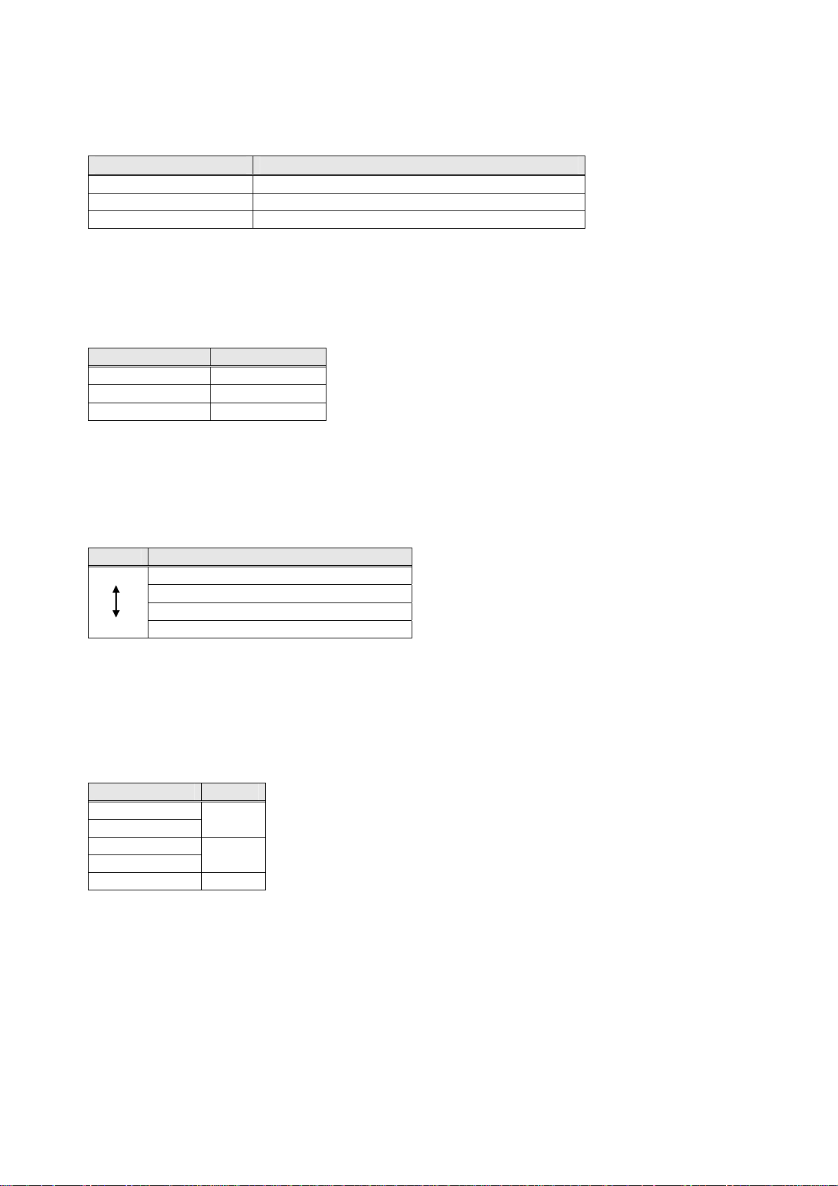
5.3. Starting/Stopping the Beeper/Vibrator
The beeper/vibrator is activated or deactivated by the following functions:
Function Used to:
BHT_StartBeep
BHT_StartBeeperOnly
BHT_StartVibratorOnly Activate the vibrator.
The functions listed above start the beeper/vibrator control and immediately pass control to the
subsequent statement or function. The actual device operation is carried out in background processing.
Specifying the frequency with value 0, 1, or 2 sounds the beeper with the frequency listed below. If any
other value is specified, the beeper sounds at the maximum volume.
Parameter value Frequency (Hz)
0 698
1 1396
2 2793
If the suspend or critical power states are turned OFF while the beeper is sounding or the vibrator is
vibrating, the BHT resumes with both the beeper and vibrator stopped when the unit is next resumed.
Activate the selected device (beeper or vibrator).
Activate the beeper.
5.4. Priority Orders between Events that Activate the Beeper/Vibrator
There are priority orders between events that activate the beeper/vibrator as listed below.
Priority Event that activate the beeper/vibrator
Higher
Lower
When the beeper or vibrator is being driven by any event, the lower priority event (if happens) activates
no beeper or vibrator but the same or higher priority event (if happens) overrides the currently operating
beeper or vibrator and newly activates the beeper or vibrator.
System error
Completion of barcode reading
Setting in applications
Key clicks or screen taps
5.5. Beeper Volume Patterns
The beeper is activated according to the beeper volume as listed below.
Beeper volume Volume
1 (lowest)
2
3
4
5 (highest) Loud
Soft
Mid
12
Page 18

Chapter 6. Keys and Trigger Switch Control
6.1. Outline
In addition to the processing for depressed or released keys and trigger switch, the BHT OS controls the
following functions assigned to them.
(1) Specifying the shift key operation mode
(2) Assigning functions to the magic keys (M1 to M3)
(3) Supporting the alphabet entry mode (in addition to the numeric entry mode)
(4) Function mode
(5) Key click sound
(6) Keyboard type acquisition
Furthermore, both the 27-key pad and 42-key pad keyboard types are supported.
13
Page 19

6.2. Setting the Keys and Trigger Switch
The BHT_SetSysSettingDW (DWORD dwCtrlCode, DWORD dwSysParam)
and BHT_GetSysSettingDW (DWORD dwCtrlCode, DWORD *pdwSysParam) functions write or read the
keys and trigger switch parameters.
Parameter
name
Shift key
operation
mode
Assignment to
M1 key
Assignment to
M2 key
Assignment to
M3 key
Entry mode DW R/W
Enable/disable
alphabet entry
switching key
Function
mode
Type R/W Control code Parameter value Default
DW R/W
DW R/W
DW R/W
DW R/W
DW R/W
DW R/W
BHT_KEY
_SHIFT_MODE
BHT_KEY
_M1_MODE
BHT_KEY
_M2_MODE
BHT_KEY
_M3_MODE
BHT_KEY
_INPUT_METHOD
BHT_DISABLE
_KEYMODE
_CHANGE_KEY
BHT_KEY
_FUNCTION
KEY_NON_LOCK
: Non-lock mode
KEY_ONE_TIME
: Onetime lock mode
MAGIC_FUNC_NONE
: Ignore the depressed key
MAGIC_FUNC_ENTER
: Treat as ENT key
MAGIC_FUNC_TRG
: Treat as trigger switch
MAGIC_FUNC_SHIFT
: Treat as SF key
MAGIC_FUNC_ALT
: Treat as ALT key
MAGIC_FUNC_CTRL
: Treat as CTRL key
MAGIC_FUNC_BLT
: Treat as backlight function
on/off key
MAGIC_FUNC_TAB
: Treat as TAB key
MAGIC_FUNC_CLEAR
: Treat as CLEAR key
MAGIC_FUNC_USERDEF
: User-defined code (*1)
INPUT_METHOD
_NUMERIC
: Numeric entry mode
INPUT_METHOD
_ALPHABET
: Alphabet entry mode 1
INPUT_METHOD
_ALPHABET 2
: Alphabet entry mode 2 (*2)
ENABLE_KEY
_TOCHANGE
_ALPHABET
: Enable alphabet entry
DISABLE_KEY
_TOCHANGE_ALPHABET
: Disable alphabet entry
KEY_FUNCTION_ON
: Function mode
KEY_FUNCTION_OFF
: Non-function mode
(*1) User-defined codes can only be acquired.
(*2) Alphabet entry mode 2 is only available with the 27-key pad.
KEY_NON_LOCK
MAGIC_FUNC_TAB
MAGIC_FUNC
_NONE
MAGIC_FUNC
_TRG
27-key type:
INPUT_METHOD
_NUMERIC
42-key type:
INPUT_METHOD
_ALPHABET
ENABLE_KEY
_TOCHANGE
_ALPHABET
KEY_FUNCTION
_OFF
Validating
timing
Immediately
after setting
Immediately
after setting
Immediately
after setting
Immediately
after setting
Immediately
after setting
Immediately
after setting
Immediately
after setting
14
Page 20
6.3. Shift Key Operation Mode
The shift key operation mode works as follows:
Shift key operation
mode
Non-lock mode - The keypad is shifted when the Shift key is held down.
Onetime lock
mode
- The shift status is cleared immediately after releasing a key when in the
shift status from the time the key is pressed until it is released while the
shift key is held down and after it is released.
Description
6.4. Magic Key Control
The table below lists the virtual key codes and character codes when magic keys (M1 to M3) are pressed.
Parameter value
MAGIC_FUNC_NONE [M1] key VK_M1 C1 - [M2] key VK_M2 C2 - [M3] key VK_M3 C3 - MAGIC_FUNC_ENTER VK_RETURN 0D 0D(CR) 0D(CR)
MAGIC_FUNC_TRG (*1) - MAGIC_FUNC_SHIFT VK_SHIFT 10 - MAGIC_FUNC_CTRL VK_CONTROL 11 - MAGIC_FUNC_ALT VK_MENU 12 - MAGIC_FUNC_BLT (*1) - MAGIC_FUNC_TAB VK_TAB 09 09 (tab) 09 (tab)
MAGIC_FUNC_LASER (*1) - MAGIC_FUNC_CLEAR VK_CLEAR 0C - MAGIC_FUNC_USERDEF (*2)
(*1) Returns the same virtual key code as when “MAGIC_FUNC_NONE” is assigned.
(*2) Notified virtual key codes are user-defined codes. In such a case, functions assigned to keys such as
the following cannot be executed.
- Changing the entry mode by pressing the [AL] key to which the function has been assigned.
- Backing up the registry by pressing the [SF] key to which the function has been assigned and the
[Power] key.
- Switching between backlight enable and backlight disable by assigning the function to [SF] + [M3].
Virtual key code Character code
Constant Value When not shifted Shifted
15
Page 21
A
A
6.5. Assigning a User-Defined Key Code to the Magic Keys
Apart from the previously mentioned functions, optional keys can be applied to the magic keys following
the method below.
With this function it is possible to assign keys to the magic keys that do not exist in the BHT-700, or to
execute the equivalent of a multi-key function by pressing a magic key once.
6.5.1. Assignment Method
The steps for setting user-defined key codes for the magic keys are as follows:
(1) Save a user-defined code settings file with the filename “MKeyDef.txt” in the FLASH folder of the BHT.
(2) Choose the key you wish to set from the key definition menu in the BhtShell (for further details refer to
the “BHT-700BB/700BWB/700BWBG-CE User’s Manual” or “BHT-700QWBG-CE User’s Manual”).
Backup files can be created with a backup registry.
6.5.2. User-Defined Code Settings File (MKeyDef.txt)
(1) File name
“MKeyDef.txt” (fixed)
(2) Format
<Character string inside the combo box>,<Defined code number>,<Defined code 1>,…,<Defined
code 4>
Item Display Method Setting Content
Character string inside the
combo box
Defined code number decimal number A user-defined code specified as a
Defined code 1 through 4 hexadecimal
[Ex] Setting a user-defined key code of “Alt + X” and “Alt + Y” to be added to the combo box list.
(*) If there is a mistake in the format of a line in the MKeyDef.txt file, that line will be ignored and removed
(*) Even if the MKeyDef.txt file is deleted, key code settings will be retained (the BhtShell will display
LT+X, 2, 0x12, 0x58
LT+Y, 2, 0x12, 0x59
from the BhtShell key definition menu.
"None"). When a different function is designated in the BhtShell, the previous key code settings will be
replaced.
Character string A character string containing up to
64 characters. Extra characters will
be ignored.
number between 1 and 4.
The virtual key code you wish to
number
assign.
16
Page 22

6.6. Key Input Modes
The BHT-700 key pad has the following three key entry modes.
(1) Numeric entry mode
This mode allows you to type in numeric data with the numeric keys.
(2) Alphabet entry mode 1
In the 27-key pad, use the numeric keys to type in alphabet letters in the same way as he/she uses a
cellular phone.
In the 42-key pad, use the alphabet keys to type in alphabet letters directly.
(3) Alphabet entry mode 2 (27-key pad only)
This entry mode is for alphabet entry at programs running on the computer when using terminal
services such as a remote desktop connection.
Similarly to aphabet entry mode 1, alphabet letters are entered using the numeric keys.
6.6.1. Numeric Entry Mode
The numeric entry mode starts by:
(1) calling the BHT_SetSysSettingDW (BHT_KEY_INPUT_METHOD, INPUT_METHOD_NUMERIC)
function.
(2) pressing the [AL] key when in alphabet entry mode 2 (27-key pad). (*1), or
pressing the [NUM] key when in alphabet entry mode 1 (42-key pad). (*1)
(*1) Effective only when the key entry mode transition key is not disabled.
Pressing keys in this mode returns virtual key codes and character codes specified in Appendix A.
6.6.2. Alphabet Entry Mode 1 (27 key pad)
The alphabet entry mode 1 starts by:
(1) calling the BHT_SetSysSettingDW (BHT_KEY_INPUT_METHOD, INPUT_METHOD_ALPHABET)
function.
(2) pressing the AL key(*2) in the numeric entry mode.
The alphabet entry mode 1 terminates by:
(1) switching to any other entry mode with the BHT_SetSysSettingDW function.
(2) pressing the AL key(*2) in the numeric entry mode.
(*2) The key takes effect only when it is not disabled by the BHT_DISABLE_KEYMODE-
CHANGE_KEY.
In the 27-key pad alphabet entry mode 1, alphabet characters can be entered using an alphabet
character similar to that used on a cellular phones.
(1) When changing to alphabet entry mode 1, an unestablished character display window similar to that
shown below displays.
Unestablished characters display.
The unestablished character display window has the following features.
- This window can be moved by using the stylus.
- The focus is not transferred to the unestablished character display window.
- The unestablished character display window always displays in the foreground.
Furthermore, the following icon displays in the task bar when in alphabet entry mode 1.
17
Page 23

(2) If keys [0] to [9] or the [.] key is pressed, the pressed key becomes an unestablished character and
displays in the unestablished character display window. The character then reverts to a character
code when any of these keys becomes established.
Press any of the following keys below to establish unestablished characters.
- Keys [0] to [9] or [.] that differ from the key pressed at the unestablished character
- [ENT] key
- “MAGIC_FUNC_ENTER” assigned to the magic keys
- Keys [F1] to [F12]
(3) Keys used for alphabet entry 1
The table below lists keys whose operations are different from those in the numeric entry mode.
Use this key To do this
0 to 9 and
period (.) keys
ENT key
BS key
F1 to F12 Key
Magic key
AL key
6.6.3. Alphabet Entry Mode 1 (42-Key Pad)
Alphabet entry mode 1 starts by:
(1) calling the BHT_SetSysSettingDW (BHT_KEY_INPUT_METHOD, INPUT_METHOD_ALPHABET)
function.
(2) pressing the [NUM] key when in numeric entry mode. (*2)
Alphabet entry mode 1 terminates by:
(1) switching to any other entry mode with
the BHT_SetSysSettingDW(BHT_KEY_INPUT_METHOD, INPUT_METHOD_XXXXXX) function.
(2) pressing the [NUM] key. (*2)
(*2) Effective only when the key entry mode transition key is not disabled.
When keys are pressed in this mode, virtual key codes and character codes are returned in accordance
with “Appendix A. Keyboard Arrangement, Virtual Key Codes and Character Codes”
-“A.2.2. Virtual Key Codes and Character Codes”.
Enter alphabets. For alphabets assigned to these keys, refer to
“Appendix A. Keyboard Arrangement, Virtual Key Codes and
Character Codes” – “A.1.3. Character Codes in Alphabet Entry Mode.”
Establish an unestablished key if any.
If there is no unestablished key, the same character code as in the
numeric entry mode is returned.
Clear an unestablished key if any.
If there is no unestablished key, the same character code as in the
numeric entry mode is returned.
Establish an unestablished key if any.
If there is no unestablished key, the same character code as in the
numeric entry mode is returned.
Establish an unestablished key if any when the
MAGIC_FUNC_ENTER is assigned to these keys.
If there is no unestablished key, the same character code as in the
numeric entry mode is returned.
Clears unestablished keys if any exist and switches to numeric entry
mode.
18
Page 24
6.6.4. Alphabet Entry Mode 2 (27-key pad only)
Alphabet entry mode 2 starts by:
(1) calling the BHT_SetSysSettingDW (BHT_KEY_INPUT_METHOD, INPUT_METHOD_ALPHABET2)
function.
(2) pressing the [AL] key when in alphabet entry mode 1. (*1)
Alphabet entry mode 2 terminates by:
(1) switching to any other entry mode with the BHT_SetSysSettingDW (BHT_KEY_INPUT_METHOD,
INPUT_METHOD_XXXXXX) function.
(2) pressing the [AL] key. (*1)
(*1) Effective only when the key entry mode transition key is not disabled.
Similarly to alphabet entry mode 1, alphabet letters can also be entered in alphabet entry mode 2 using
the same method used when entering alphabet letters with a cellular phone.
(1) The following icon below displays in the task bar when starting alphabet entry mode 2.
The unestablished character display window does not display.
(2) If keys [0] to [9] or the [.] key is pressed, characters assigned to those keys display at the current
cursor position. By pressing the same key(s) again, assigned characters display sequentially.
Press a different key to establish the entered character(s).
(3) Keys used in alphabet entry mode 2
The table below lists keys whose operations are different from those in the numeric entry mode.
Use this key To do this
[0] to [9] and
period (.) keys
[AL] key Switches to numeric entry mode.
Used to enter alphabet letters. For details of alphabet letters assigned to these
keys, refer to “Appendix A. Keyboard Arrangement, Virtual Key Codes and
Character Codes” – “A.1.3. Character Codes in Alphabet Entry Mode.”
19
Page 25

6.7. Function Mode
Use either of the methods below to enable function mode.
(1) Call up the BHT_SetSysSettingDW (BHT_KEY_FUNCTION,KEY_FUNCTION_ON) function.
(2) Press the [FN] key when in function mode.
Use either of the methods below to disable function mode and return to non-function mode.
(1) Call up the BHT_SetSysSettingDW (BHT_KEY_FUNCTION,KEY_FUNCTION_OFF) function.
(2) Press the [FN] key when in function mode.
Non-function mode is enabled as the default when the unit is booted up.
The following icon displays in the task bar when in function mode.
If a key is pressed when in function mode, a virtual key code or character code is returned as outlined
in ”Appendix A. Keyboard Arrangement, Virtual Key Codes, and Character Codes”.
6.8. Key Clicks
When the keys are pressed, the BHT clicks as specified below. Note that pressing the power key does
not click.
Parameter
value
(dwSysParam)
0: OFF
1: Soft
2: Loud
CLICK_SOUND
_OFF: Prohibit
CLICK_SOUND
_ON: Allow
Default Validating timing
2
CLICK_SOUND_OFF
first key press after
setting
first trigger key press
after setting
Parameter name Type R/W
Key click volume DW R/W
Trigger switch
clicks
DW R/W
Control code
(dwCtrlCode)
BHT_BEEP_VIB
_KEY
BHT_BEEP_VIB
_TRGKEY
6.9. Acquisition of Keypad Type
The BHT_GetSysSettingDW (DWORD dwCtrlCode,DWORD *pdwSysParam) function reads the keypad
type.
Parameter name Type R/W Control code Parameter value Default Validating timing
Keypad type DW R BHT_KEYBOARD_TYPE
KEYBOARD_TYPE1
: 27-key pad
KEYBOARD_TYPE2
: 42-key
- -
20
Page 26

6.10. Auto Repeat Function
The keys used to perform auto repeat are listed in the following table. Whether auto repeat function for
each key is enabled or disabled is listed in the following table.
Key 27-key pad 42-key pad
[0] to [9] key and
Period ([.]) key
[A] to [Z] key - ●
[BS] key ● ●
[C] key ● ●
[W][X][S][T] key
[F1] to [F12] key ● ●
[SF] key - [FN] key - [ENT] key - [TAB] key ● ●
[AL] key - N/A
[NUM] key N/A [ESC] key - [SCAN] key - Magic keys - No key assignment : -
Power key - -
* ● : Auto repeat performed , - : Auto repeat not performed
- In Numeric entry mode : ●
- In Alphabet entry mode : -
● ●
- [ENT]key : -
- Trigger key : -
- Shift key : -
- Backlight control key : -
- [TAB] key : ●
- [CTRL] key : -
- [ALT] key : -
- [CLEAR] key : -
- User-defined code : -
- No key assignment : -
- [ENT] key : -
- Trigger key : -
- Shift key : -
- Backlight contorol key : -
- [TAB] key : ●
- [CTRL] key : -
- [ALT] key : -
- [CLEAR] key : -
- User-defined code : -
●
21
Page 27
Chapter 7. LCD Status Indication
7.1. Outline
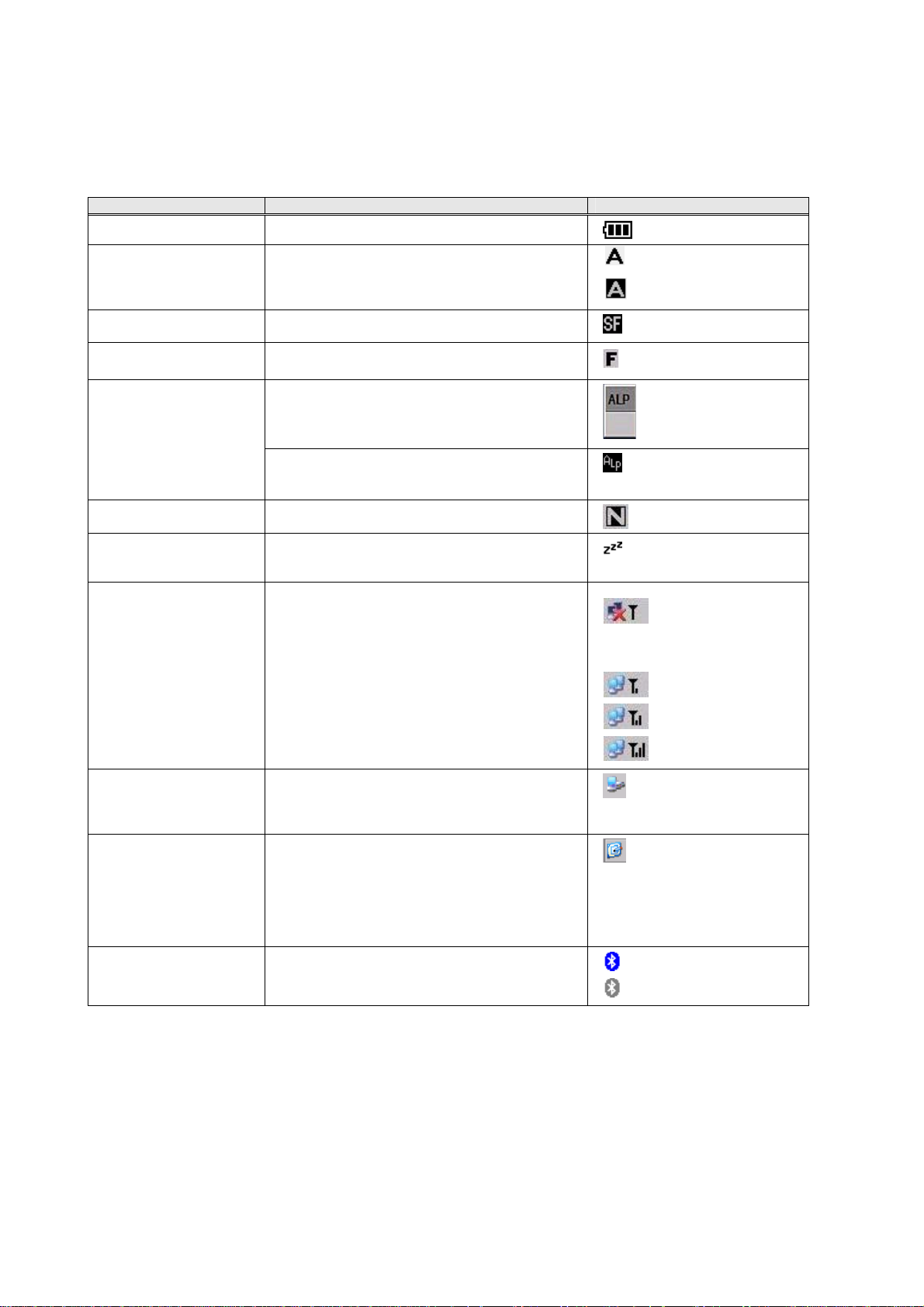
The status of the BHT is displayed on the LCD as specified below.
Status Description Icon
Battery voltage level Displays the battery voltage in five levels.
Software keyboard
display state
Keypad shift state Displays the icon when the keypad is shifted.
Function state Displays the icon when in function mode.
Alphabet input state
(27-key pad only)
Numeric entry status
(42-key pad only)
Standby state Displays this icon when the CPU comes to be on
Synchronization state Displays the open state of the wireless device
ActiveSync Displays this icon when the BHT is
Desktop display Switches the screen between the application
Bluetooth power status Displays the Bluetooth power status.
Shows whether the software keyboard is
displayed or hidden. Tapping this icon toggles the
software keyboard on and off.
Displays the ALP window when the alphabet
input function is activated. An unestablished
character appears in this ALP window.
Displays the icon when the alphabet input
function is activated.
Displays when in numeric entry mode.
standby.
and the radio field intensity.
communicating with the PC via Microsoft
ActiveSync (not using LAN).
execution display and desktop display. Tapping
this icon when an application program is running
switches the screen to the desktop display.
Tapping it again returns to the application
execution display.
No icons display if the unit is not equipped with a
Bluetooth device.
: The software keyboard is
displayed.
: The software keyboard is
hidden.
The wireless device is open.
The wireless device is open and
the wireless link is established
with an access point.
: Power OFF
: Radio field intensity
(Low)
: Radio field intensity
(Medium)
: Radio field intensity
(High)
: Power ON
22
Page 28
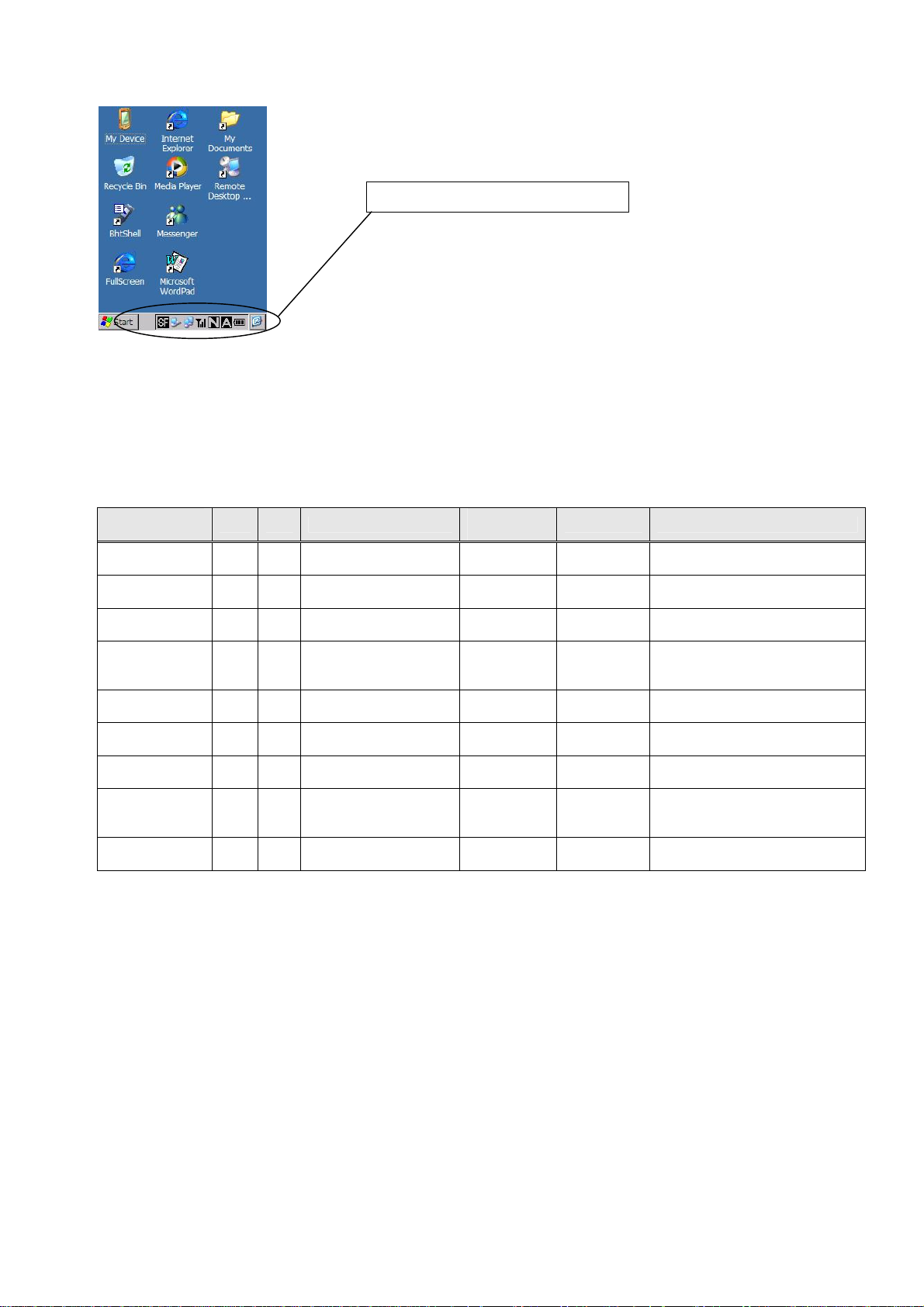
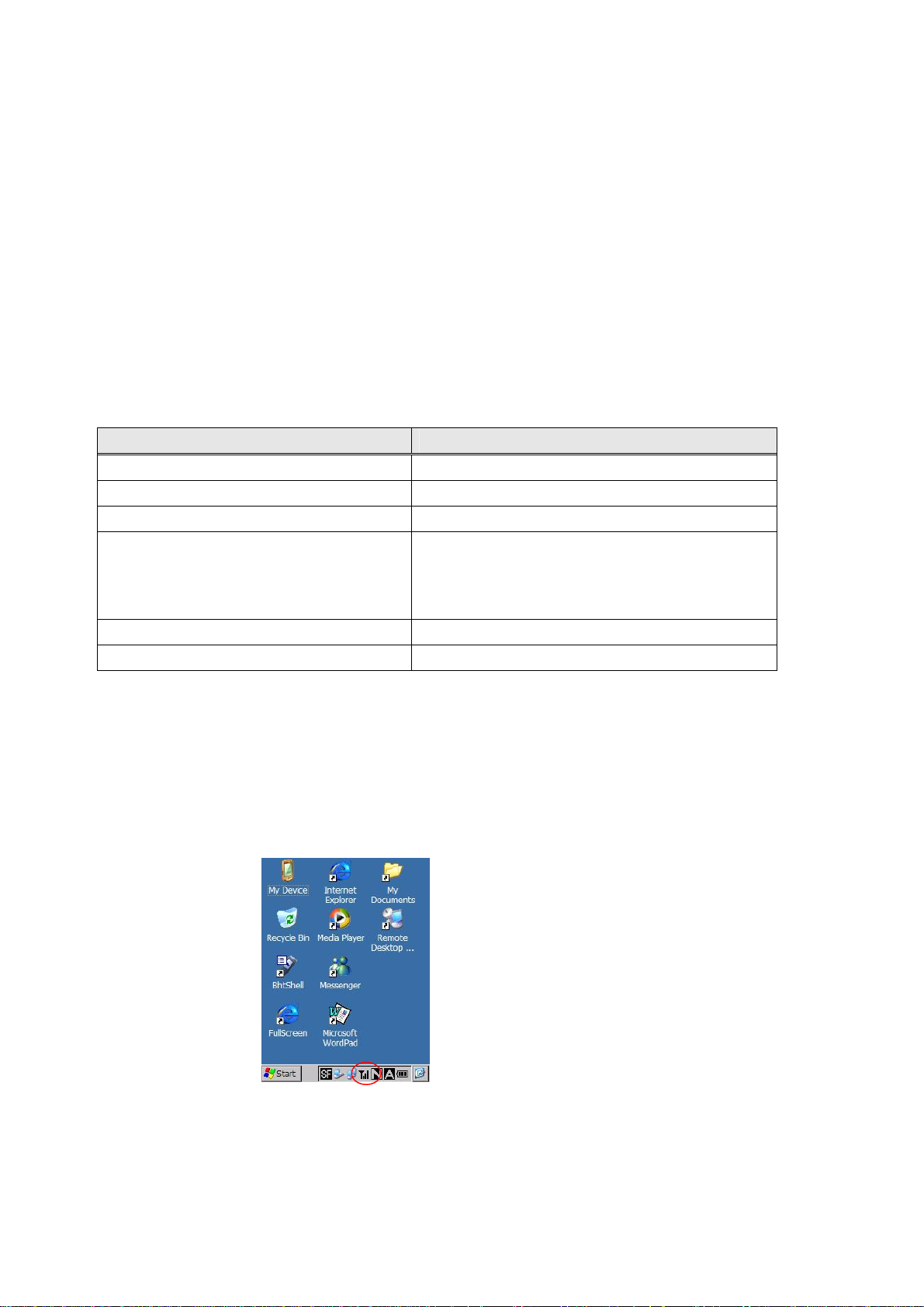
(Display sample of icons)
Status indicator icons in the task bar
7.2. Setting the LCD Status Indication
The BHT_SetSysSettingDW (DWORD dwCtrlCode, DWORD dwSysParam) and BHT_GetSysSettingDW
(DWORD dwCtrlCode, DWORD *pdwSysParam) functions write or read the LCD status indication as
specified below.
Battery voltage
level icon
Software
keyboard icon
Keypad shift
icon
Alphabet input
icon(27-key pad
only)
Synchronization
state icon
Standby state
icon
Function state
icon
Numeric entry
status (42-key
pad only)
Bluetooth
power status
Parameter
name
Type R/W Control code
DW R/W
DW R/W
DW R/W
DW R/W
DW R/W
DW R/W
DW R/W BHT_ICON_FUNC
DW R/W BHT_ICON_NUMERIC
DW R/W
BHT_ICON
_BATTERY
BHT_ICON
_SIP
BHT_ICON
_SHIFTKEY
BHT_ICON
_IN_ALPHA
BHT_ICON
_RADIO_INTENSE
BHT_ICON
_STANDBY
BHT_ICON
_BLUETOOTH
Parameter
value
0: Hide
1: Display
0: Hide
1: Display
0: Hide
1: Display
0: Hide
1: Display
0: Hide
1: Display
0: Hide
1: Display
0: Hide
1: Display
0: Hide
1: Display
0: Hide
1: Display
Default Validating timing
1
1 Immediately after setting
1 Immediately after setting
1 Immediately after setting
1 Immediately after setting
0 Immediately after setting
1 Immediately after setting
1 Immediately after setting
0 Immediately after setting
Immediately after setting
23
Page 29

Chapter 8. Power Management
8.1. Outline
The power management functions switch the system powering state.
The following four system power states exist.
(1) Power ON
(2) Standby
(3) Suspned (*1)
(4) Critical OFF (*2)
(*1) Suspend
The BHT will be suspended when the power is turned off with the power key or auto power off feature.
(*2) Critical OFF
The BHT will become critical off when the power is turned off due to battery voltage drop or battery cover
unlocked.
Notes
- No processing is performed when the BHT is on standby.
- When the SD memory card is used, disable the standby function before accessing the card.
24
Page 30

8.2. Standby
8.2.1. Switching to the Standby State
The BHT switches from the power ON state to the standby state when any of the following conditions
arises:
(1) When the standby transition timeout occurs after a standby transition prohibited event (listed below)
is completed.
(2) When waiting for the event specified by the BHT_WaitStandbyEvent function with the standby
transition prohibited event completed.
(3) When the standby transition prohibited event is completed while waiting for the event specified by
the BHT_WaitStandbyEvent function to occur.
8.2.2. Standby Transition Prohibited Events
The following items are standby transition prohibited events.
- Key being pressed
- Touch panel being tapped
- Screen being refreshed
- Beeper/vibrator in operation
- Key click sound/touch panel tap sound in operation
- Backlight being ON (excludes those times when continuously ON)
- Reading barcodes
- IrDA interface port opened
- Connector interface port opened
- USB interface opened
- Wireless device opened
- During USB-LAN communication
- Flash memory being erased or written
- RTC being accessed
- Indicator LED being ON
- System message being displayed
- Bluetooth device power being ON
- Explorer displayed
- Standby transition time set to "0"
8.2.3. Setting the Standby Transition Timeout
The BHT_SetSysSettingDW (DWORD dwCtrlCode, DWORD dwSysParam) and BHT_GetSysSettingDW
(DWORD dwCtrlCode, DWORD *pdwSysParam) functions write or read the standby transition timeout as
specified below.
Parameter name Type R/W Control code Parameter value Defaults Validating timing
Standby transition timeout
(in units of 100 msec)
DW R/W BHT_PM_STBYTIME
0: Disable
1 - 255
10
(1 sec)
Immediately after setting
25
Page 31

8.3. Suspend
8.3.1. Setting the Standby Transition Timeout
The BHT switches to the suspend state when any of the following conditions arises:
(1) When the power is on, the power key is held down for the effective held-down time (for switching to
the suspend state) or more.
(2) An auto power-off timeout occurs after one of the suspend transition prohibited events (listed below)
is completed.
(3) When the power OFF function is called.
8.3.2. Suspend Transition Prohibited Events
The following items are suspend transition prohibited events.
- Key press (other than power key) authentication
- Touch panel tap authentication
- When ActiveSync connection established (IrDA and USB)
- When auto power OFF time is set to "0"
- When the following registry value is set to "0" with a wireless connection established
[HKEY_LOCAL_MACHINE\Comm\CXPort]
"NoIdleTimerReset"=dword : 0
Furthermore, the auto power OFF time is reset upon the occurrence of the following events.
- When a serial communication event occurs (IrDA and USB)
- When the SystemIdleTimerReset() function is executed
- When an event with event object name "PowerManager, ActivityTimer, or UserActivity" is set
8.3.3. Setting the Auto Power-off Timeout
The BHT_SetSysSettingDW (DWORD dwCtrlCode, DWORD dwSysParam) and BHT_GetSysSettingDW
(DWORD dwCtrlCode, DWORD *pdwSysParam) functions write or read the auto power-off timeout as
specified below.
Parameter name Type R/W Control code Parameter value Defaults Validating timing
Auto power-off timeout
(sec.)
(When battery-driven)
Auto power-off timeout
(sec.)
(When placed on the CU)
DW R/W
DW R/W
BHT_PM
_BATTPOWEROFF
BHT_PM
_EXTPOWEROFF
8.3.4. Setting the Effective Held-down Time of the Power Key for Switching to the Suspend State
The BHT_SetSysSettingDW (DWORD dwCtrlCode, DWORD dwSysParam) and BHT_GetSysSettingDW
(DWORD dwCtrlCode, DWORD *pdwSysParam) functions write or read the effective held-down time of
the power key for switching to the suspend state as specified below.
Parameter name Type R/W Control code
Effective held-down time of the
power key for switching to the
suspend state (in units of 100 msec)
DW R/W
BHT_PWRDOWN_KEY
_WAIT_TIME
Saving the Registry
If the BHT is switched to the suspend state by pressing the power key with the SF (*1) key held down,
the Registry will be saved into the flash memory.
(*1) Here, this means only the key marked “SF.” The Registry will not be saved even if you press the
power key while holding down the magic key to which the SF key function is assigned.
0: Disable
1 0xFFFFFFFF
0: Disable
1 0xFFFFFFFF
180
(3 min.)
Parameter
value
1 - 255 5
Immediately after
setting
Immediately after
0
setting
Defaults
Validating
timing
Immediately
after setting
26
Page 32
Chapter 9. Battery State
9.1. Outline
The battery status can be ascertained using the following methods.
(1) Battery status acquisition
(2) Battery voltage icon
(3) Low battery voltage warning message display
9.2. Battery Voltage Acquisition
The BHT_GetPowerStatus function can be used to ascertain whether the BHT is on the CU, and acquires
the battery level, battery voltage, and battery type.
9.3. Battery Voltage Icon
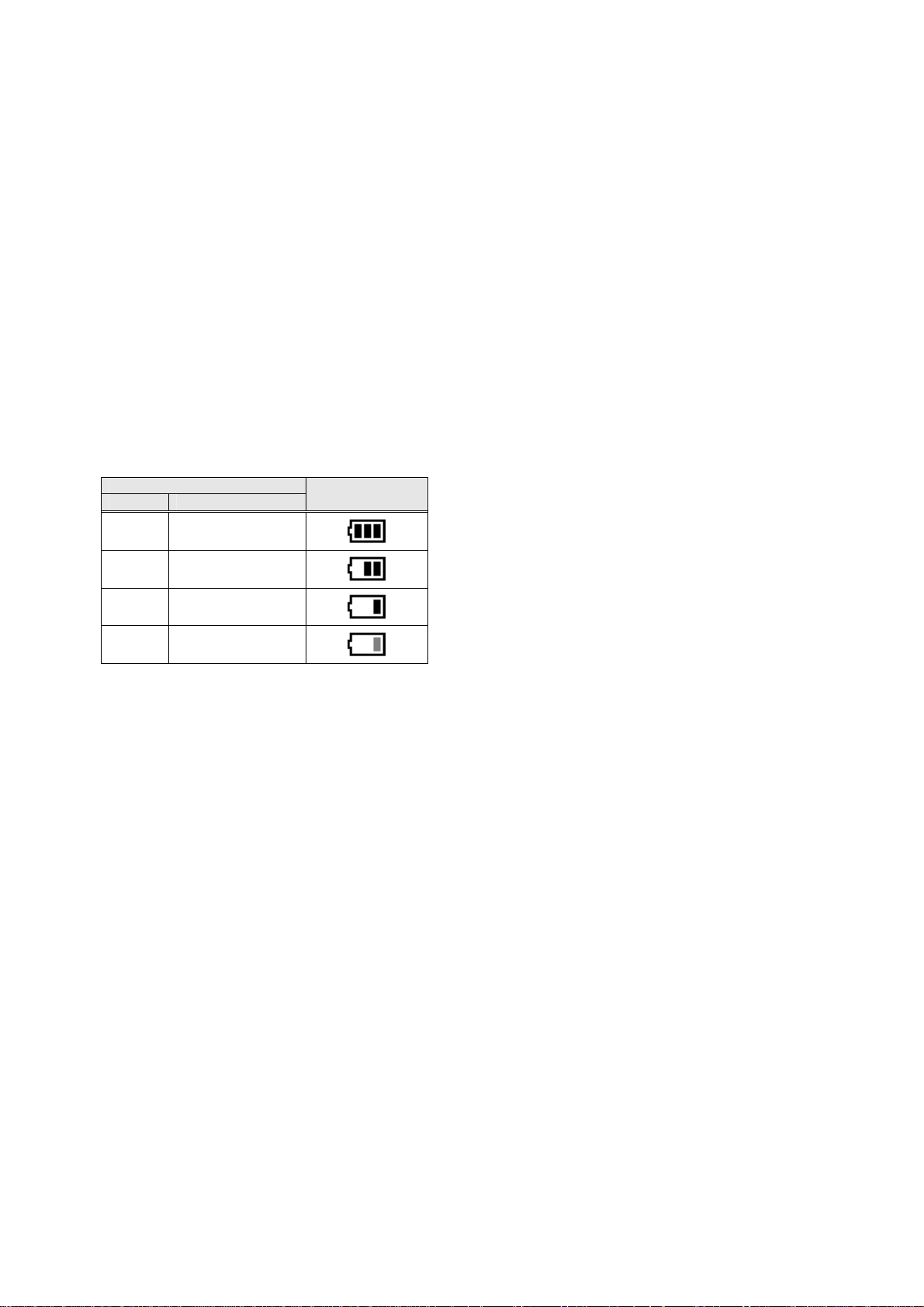
The battery voltage status is indicated with the icons below if the battery voltage status display is
authorized.
Battery voltage level
Level Voltage
Battey Voltage
Icon
High 3.9 V or higher
Medium
Low
Warning
3.7 V or higher and
less than 3.9 V
3.6 V or higher and
less than 3.7 V
3.5V or higher and
less than 3.6 V
9.4. Battery Voltage Warning
If the output voltage of the battery cartridge drops below the specified lower limit, the BHT displays the
Level-1 message "Battery voltage has lowered." on the LCD and beeps three times. After that, it will
resume the previous regular operation.
If the battery output voltage drops further, the BHT displays the Level-2 message "Charge the battery!,"
beeps five times, and then turns itself off automatically.
27
Page 33

Chapter 10. LED
10.1. Outline
The BHT-700 has two LEDs. The display LED can be controlled from the application.
LED Color ON/OFF control from applications
Indicator LED Red and blue Possible
Charger LED Red and green Impossible
10.2. LED Control
10.2.1. Display LED
(1) Control method
The red and blue display LEDs can be turned ON and OFF using the BHT_SetNLedStatus,
BHT_SetNLedOn, and BHT_SetNLedOff functions.
Furthermore, the LED ON/OFF status can be acquired using the BHT_GetNLedStatus and
BHT_GetNLedStatusEx functions
(2) Limited items
▪ LEDs cannot be controlled when a barcode device file is open. LEDs can be controlled, however, if
LEDs are set not to illuminate when a barcode device file is open.
▪ If the function mentioned at (1) above is used to turn ON an LED from the application, the LED
remains ON even after exiting the application used to turn ON the LED. Use the function mentioned at
(1) to turn OFF the LED.
10.2.2. Charge LED
The charge LED cannot be turned ON or OFF from the application.
28
Page 34
Chapter 11. Data Communication
11.1. Outline
In wired communication between the BHT and host computer, the following interfaces are available:
(1) IrDA interface
(2) Connector interface
(3) USB client interface
(4) USB host interface
11.2. Programming for Data Communication
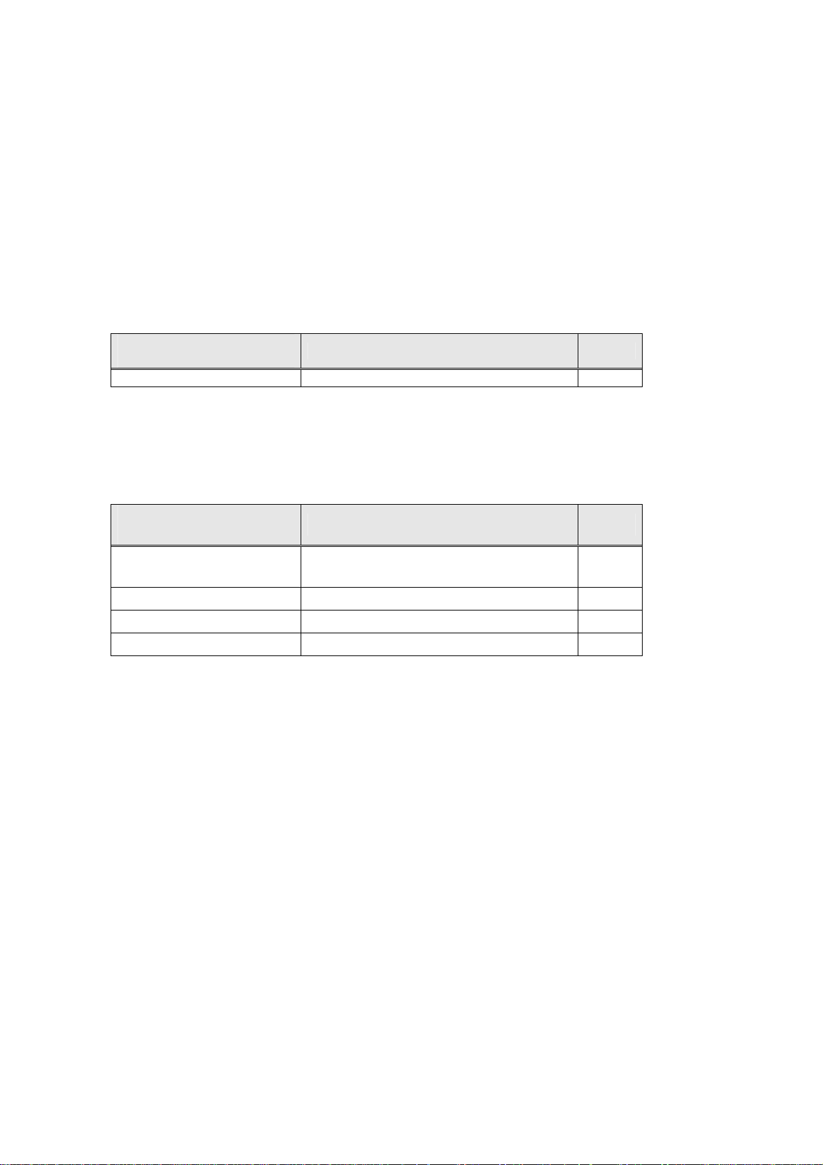
(1) IrDA interface
The IrDA interface is assigned to port 4.
Communications
parameter
Transmission speed (bps) 115200, 57600, 38400, 19200, 9600 115200
Parameters other than the transmission speed are fixed (Parity = None, Character length = 8 bits, Stop
bit length = 1 bit), since the physical layer of the IrDA interface complies with the IrDA-SIR 1.2.
(2) Connector interface
The Connector interface is assigned to port 1.
RTS and CTS signal lines are not supported.
Communications
parameter
Effective setting Default
Effective setting Default
Transmission speed (bps)
Parity None, even, or odd None
Character length 7 or 8 bits 8
Stop bit length 1 or 2 bits 1
(3) USB client interface
The USB clinet interface is used for ActiveSync connection.
(4) USB host interface
The USB host interface is used for connection with network via CU-714 and Ethernet cable. When
BHT-700 is set on CU-714, new connection named “AX-887721” is created in Control Panel.
115200,57600,38400,19200,9600,
4800,2400,1200,600,300
115200
11.3. Assigning Port Number
From COM1 to COM8 are used by system program. Assign 9 or 0 to COM port number of
communication made newly.
29
Page 35
11.4. ActiveSync
11.4.1. Establishing an ActiveSync Connection
An ActiveSync connection can be established with either of the following procedures.
(1) Manual connection via the [BhtShell] - [2:Communication] menu
(2) Auotmatic connection by placing the BHT on CU-733 connected to the computer by USB
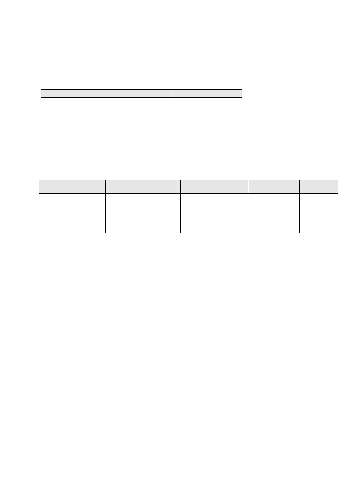
Communication I/F Manual Connection Automatic Connection
USB ● ●
IrDA ● -
Wireless ● USB-LAN (*1) ● (*1) CU-714 is necessary for USB-LAN communication.
11.4.2. ActiveSync Auto Connection Setting Method
The ActiveSync auto connection function is set and read using the BHT_SetSysSettingDW (DWORD
dwCtrlCode,DWORD dwSysParam) and BHT_GetSysSettingDW (DWORD dwCtrlCode,DWORD
*pdwSysParam) functions.
Parameter Type R/W Control Code Parameter Value Default
ActiveSync auto
connection
DW R/W
BHT_ACTSYNC
_AUTOCNCT
ACTSYNC
_AUTOCNCT_DISABLE
: Prohibited
ACTSYNC
_AUTOCNCT_USB
: USB only permitted
ACTSYNC
_AUTOCNCT
_USB
Validation
Timing
Immediately
after setting
30
Page 36
Chapter 12. Wireless Communication
12.1. Outline
12.1.1. Spread Spectrum Communications Method
Data communication is performed using TCP/IP protocol via a wireless module. Refer to item 13.2 for
details on communication program creation.
12.1.2. Configuration of Spread Spectrum System
The BHT communicates with the host computer via an access point in wireless communication.
For details, refer to the "BHT-700BB/700BWB/700BWBG-CE User's Manual" or "BHT-700QWBG-CE
User's Manual."
The table below shows the communications status transition as the state of the spread spectrum
communications device built in the BHT-700.
Spread spectrum communications device Communication
Open (power on) Impossible
Checking synchronization with access point Impossible
Synchronization complete Possible
Impossible
Roaming
End of roaming Possible
Close (power off) Impossible
If always being opened, the spread spectrum communications device will consume much power. When
the device is not in use, therefore, close it as soon as possible.
However, it will take several seconds to open the spread spectrum communications device and
synchronize it with the access point for making communications ready. Frequent opening and closing of
the device will require much time, resulting in slow response. Take into account the application purposes
of user programs when programming.
When the spread spectrum communications device is synchronized with the access point, the BHT will
display a synchronization icon on the LCD as shown below.
if the BHT is not synchronized with an access point
Possible
if synchronization with an access point is kept
31
Page 37

12.2. Programming for Wireless Communication
To connect to the wireless communications pathway, specify the following system settings in System
Menu or in a user program:
- POWER
- RADIO MODE
- ESSID (Extended Service Set ID)
- ENCRYPTION
- AUTHENTICATION
- EAP TYPE
- KEY(WEP KEY, PRE SHARED KEY)
For the procedure in System Menu, refer to the "BHT-700BB/700BWB/700BWBG-CE User's Manual" or
"BHT-700QWBG-CE User's Manual."
If no system settings are made in a user program, those made in System Menu will apply.
The following procedure is used to perform system settings in the user program.
Step 1: Select the profile to be edited.
Call the following function to edit an existing profile.
BHT_RF_IoControl (RF_UPDATE_PROFILE, NULL, 0, NULL, 0, NULL);
Call the following function to edit or create a new profile.
BHT_RF_IoControl (RF_SET_PROFILE, …);
Please refer to section “13.2.1 Wireless Communication Parameters” for details of the setting method.
Use ESSID and Infrastructure mode to specify the profile.
If no profile corresponding to the specified ESSID and Infrastructure mode combination exists, a new
profile will be created.
Step 2: Change parameter 1, parameter 2, ….., parameter N for the profile selected at Step 1.
Please refer to section “13.2.1 Wireless Communication Parameters”.
Step 3: Update the set parameters to the driver.
BHT_RF_IoControl (RF_COMMIT_PROFILE, NULL, 0, NULL, 0, NULL);
Use the highest priority profile from among those created to attempt a connection.
If connection fails, attempt to connect automatically using the highest priority profiles sequentially.
The profile with the highest priority will be the one created last.
Up to a maximum of 16 profiles can be created.
32
Page 38
12.2.1. Wireless Communication Parameters
Settable Parameters
The BHT can be used with the following security configurations by setting ZeroConfig.
- PEAP (802.1x)
- EAP-TLS (802.1x)
- PEAP (WPA)
- EAP-TLS (WPA)
- PSK (WPA)
- PEAP (WPA2)
- EAP-TLS (WPA2)
- PSK (WPA2)
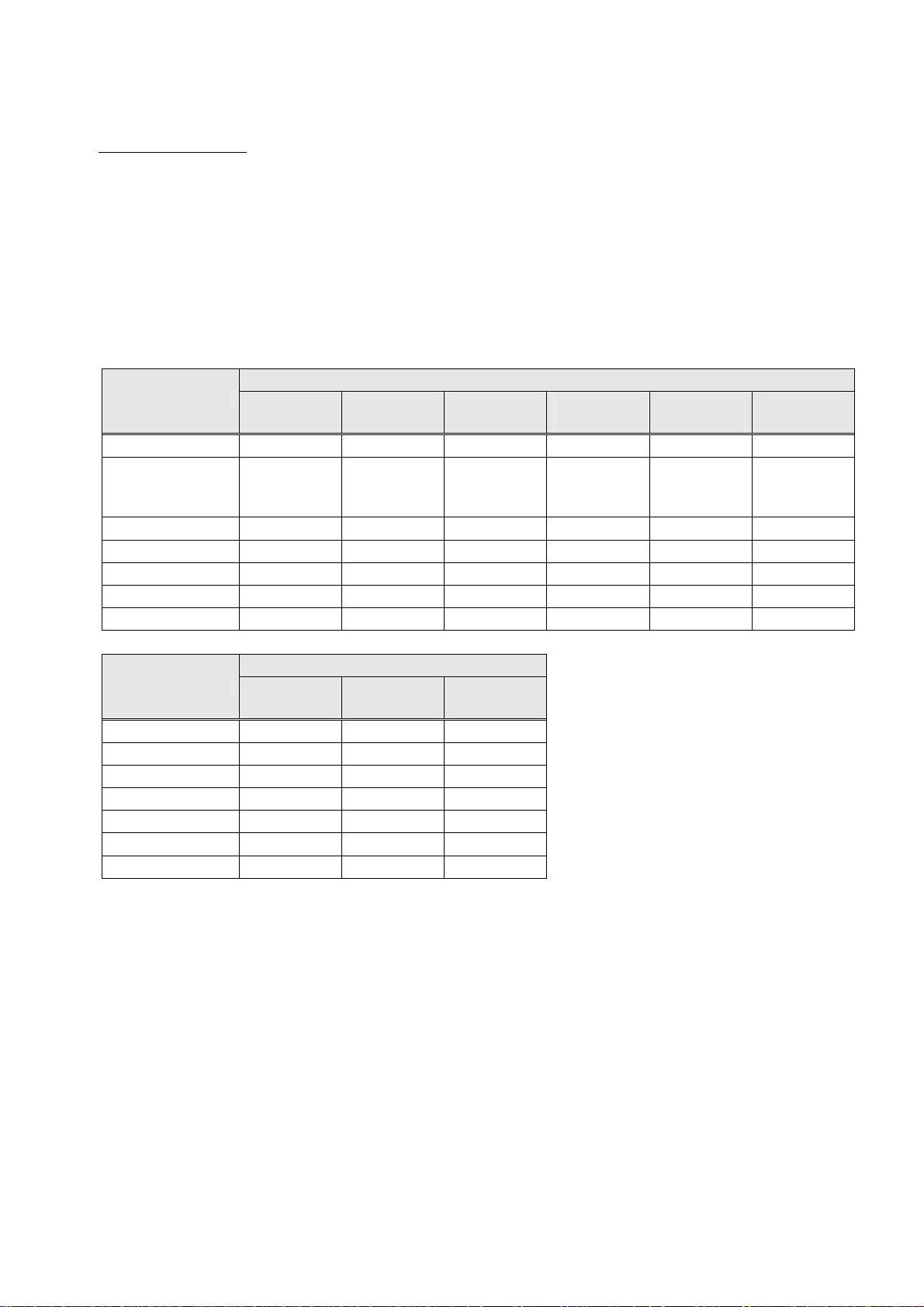
Details of the parameters used with the above security configurations are outlined in the table below.
Security
Parameter
None
PEAP
(802.1x)
EAP-TLS
(802.1x)
PEAP
(WPA)
EAP-TLS
(WPA)
Authentication OPEN OPEN OPEN WPA WPA WPA-PSK
Encryption
Disable
WEP
(static)
WEP
(auto
distribution)
WEP
(auto
distribution)
TKIP TKIP TKIP
802.1x Disable PEAP EAP-TLS PEAP EAP-TLS Disable
ESSID ● ● ● ● ● ●
Profile Priority ● ● ● ● ● ●
Pre Shared Key - - - - - ●
WEP Key ● - - - - -
Security
Parameter
PEAP
(WPA2)
EAP-TLS
(WPA2)
PSK
(WPA2)
Authentication WPA2 WPA2 WPA2-PSK
Encryption AES AES AES
802.1x PEAP EAP-TLS Disable
ESSID ● ● ●
Profile Priority ● ● ●
Pre Shared Key - - ●
WEP Key - - -
(●: Setting valid, -: Setting invalid)
PSK
(WPA)
33
Page 39
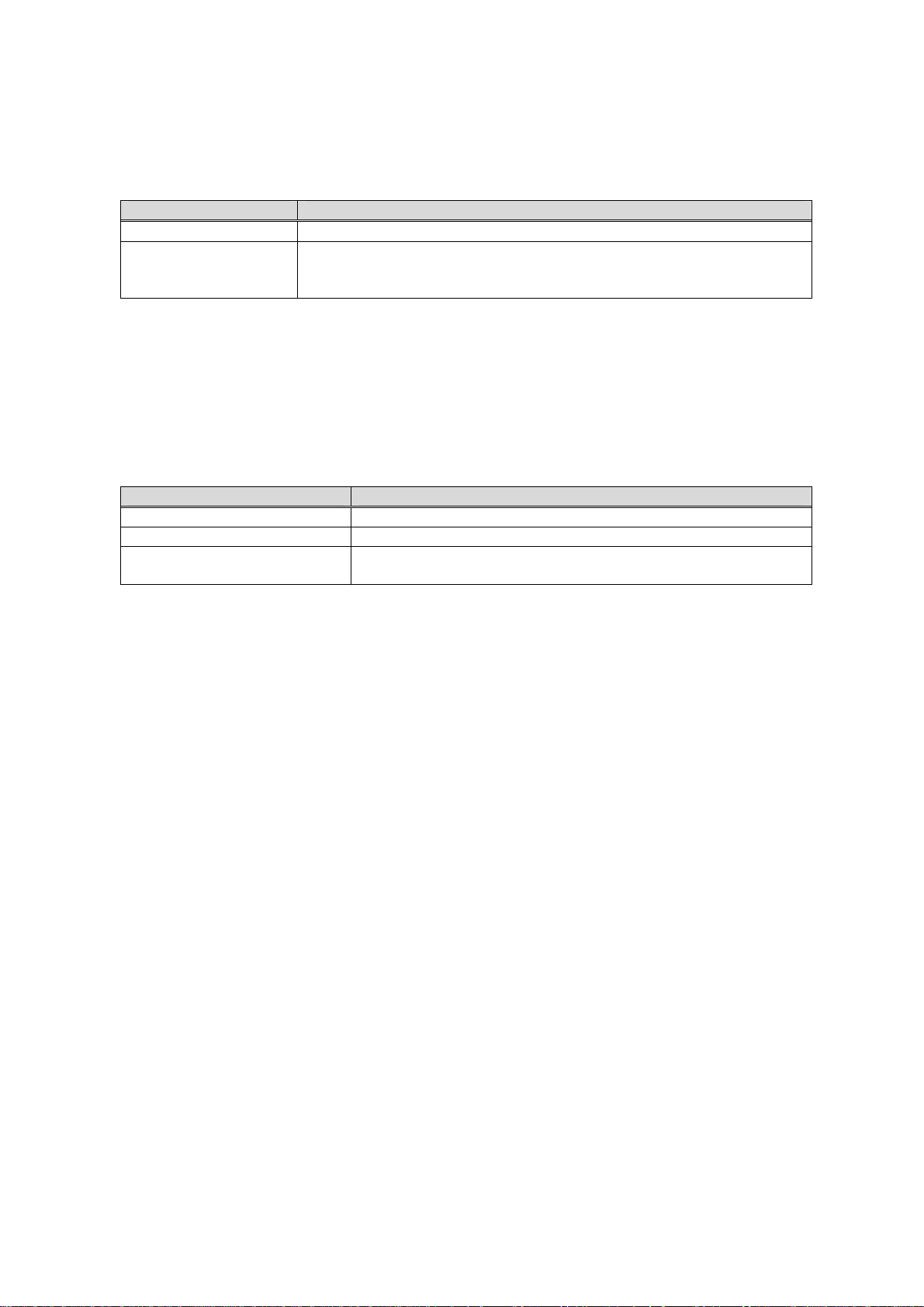
▪ POWER
Set the power mode for the wireless module built in the BHT. The following two power modes are
available. The default is P_PWRSAVE_PSP.
The set value is validated when the wireless LAN device is opened first after setting.
Power mode Power consuming state
P_PWRSAVE_CAM Consumes much power (no power saving effect)
P_PWRSAVE_PSP
[Ex.] Set the power mode to "Cosumes much power"
DWORD dwVal = P_PWRSAVE_CAM;
BHT_RF_SetParamInt (P_INT_POWERSAVE, &dwVal, sizeof(dwVal));
▪ RADIO MODE
The standard for the wireles LAN being used can be set. The following 3 patterns are available, with
the default set to 802.11b.
The set value is validated when the wireless LAN device is opened first after setting.
P_RADIOMODE_11A Operates on wireless LAN standard 802.11a.
P_RADIOMODE_11B Operates on wireless LAN standard 802.11b.
P_RADIOMODE_11B |
P_RADIOMODE_11G
[Ex.] To set the radio mode to “802.11b/g”:
DWORD dwVal = P_RADIOMODE_11B | P_RADIOMODE_11G;
BHT_RF_SetParamInt (P_INT_RADIOMODE, &dwVal, sizeof(dwVal));
▪ ESSID
Specify an ID that identifies the wireless network as a character string. The ESSID of the BHT should
be the same as the SSID of the access point. If the ESSID is not set correctly, no communication is
possible.
[Ex.] Set the "BHT700" to the ESSID (The infrastructure mode is assumed to be an “Infrastructure.”)
ST_RF_PROFILE_KEY stKey;
wcscpy(&stKey.szESSID[0], TEXT(“BHT700”)); // ESSID
stKey.dwInfraMode = INFRA_INFRASTRUCTURE; // Infrastructure
BHT_RF_IoControl (RF_SET_PROFILE, (LPVOID)&stKey, sizeof(stKey), NULL, 0, NULL);
▪ ENCRYPTION
This is the encryption method setting. A selection can be made from Prohibited, WEP, TKIP and AES.
▪ AUTHENTICATION
This is the authentication method setting. A selection can be made from Open, Shared, WPA, WPAPSK, WPA2, and WPA2-PSK.
Consumes less power (much power saving effect).
The BHT may take more time to establish the wireless link or send
response messages.
Radio mode State
Operates on wireless LAN standard 802.11b and 802.11g.
34
Page 40

▪ EAP TYPE
This is the EAP type setting. A selection can be made from Prohibited, PEAP, and TLS.
▪ KEY (WEP KEY, PRE SHARED KEY)
The encryption key (WEP KEY or PRESHARE KEY) can be set.
[Ex.] Setting to enable WEP. Set the WEP KEY to "01234567890123456789ABCDEF" (128 bit).
DWORD dwVal = P_AUTH_OPEN;
BHT_RF_SetParamInt (P_INT_AUTHENTICATE, &dwVal, sizeof(dwVal));
DWORD dwVal = P_ENCRYPT_WEP;
BHT_RF_SetParamInt (P_INT_ENCRYPTION, &dwVal, sizeof(dwVal));
DWORD dwVal = P_8021X_DISABLE;
BHT_RF_SetParamInt (P_INT_8021X, &dwVal, sizeof(dwVal));
BHT_RF_SetParamStr (P_STR_WEPKEY1,
TEXT(“01234567890123456789ABCDEF”),26);
Parameter List
Parameter Type R/W Parameter value Default
P_PWRSAVE_CAM
Power mode DW R/W
Radio mode DW R/W
Authentication
method
Encryption DW R/W
802.1x
Encryption
(EAP type)
Profile priority DW R/W 1 (high) to 16 (low) 1
Index Key DW R/W 1 to 4 1
WEP Key 1 WCS W
Pre Shared Key WCS W
Version WCS R -
MAC address WCS R - TEXT("00.00.00.00.00.00")
DW R/W
DW R/W
P_PWRSAVE_PSP
P_RADIOMODE_11A : 802.11a
P_RADIOMODE_11B : 802.11b
P_RADIOMODE_11B |
P_RADIOMODE_11G : 802.11b/g
P_AUTH_OPEN : Open
P_AUTH_SHARED : Shared
P_AUTH_WPA : WPA
P_AUTH_WPAPSK : WPA PSK
P_AUTH_WPA2 : WPA2
P_AUTH_WPA2PSK : WPA2 PSK
P_ENCRYPT_DISABLE : Prohibited
P_ENCRYPT_WEP : WEP
P_ENCRYPT_TKIP : TKIP
P_ENCRYPT_AES : AES
P_8021X_DISABLE : Prohibited
P_8021X_PEAP : PEAP
P_8021X_TLS : TLS
26-character hexadecimal notation
character string (128 bit)
10-character hexadecimal notation
character string (40 bit)
8 to 63-character ASCII character string
64-character hexadecimal notation
character string
: High power
consumption
: Low power
consumption
P_PWRSAVE_PSP
P_RADIOMODE_11B
P_AUTH_OPEN
P_ENCRYPT_DISABLE
P_8021X_DISABLE
TEXT(“”)
TEXT(“”)
Note that if you use BHT_RF_GetParamInt function for getting a value, the value preset by the
BHT_RF_SetParamInt function will be obtained.
35
Page 41
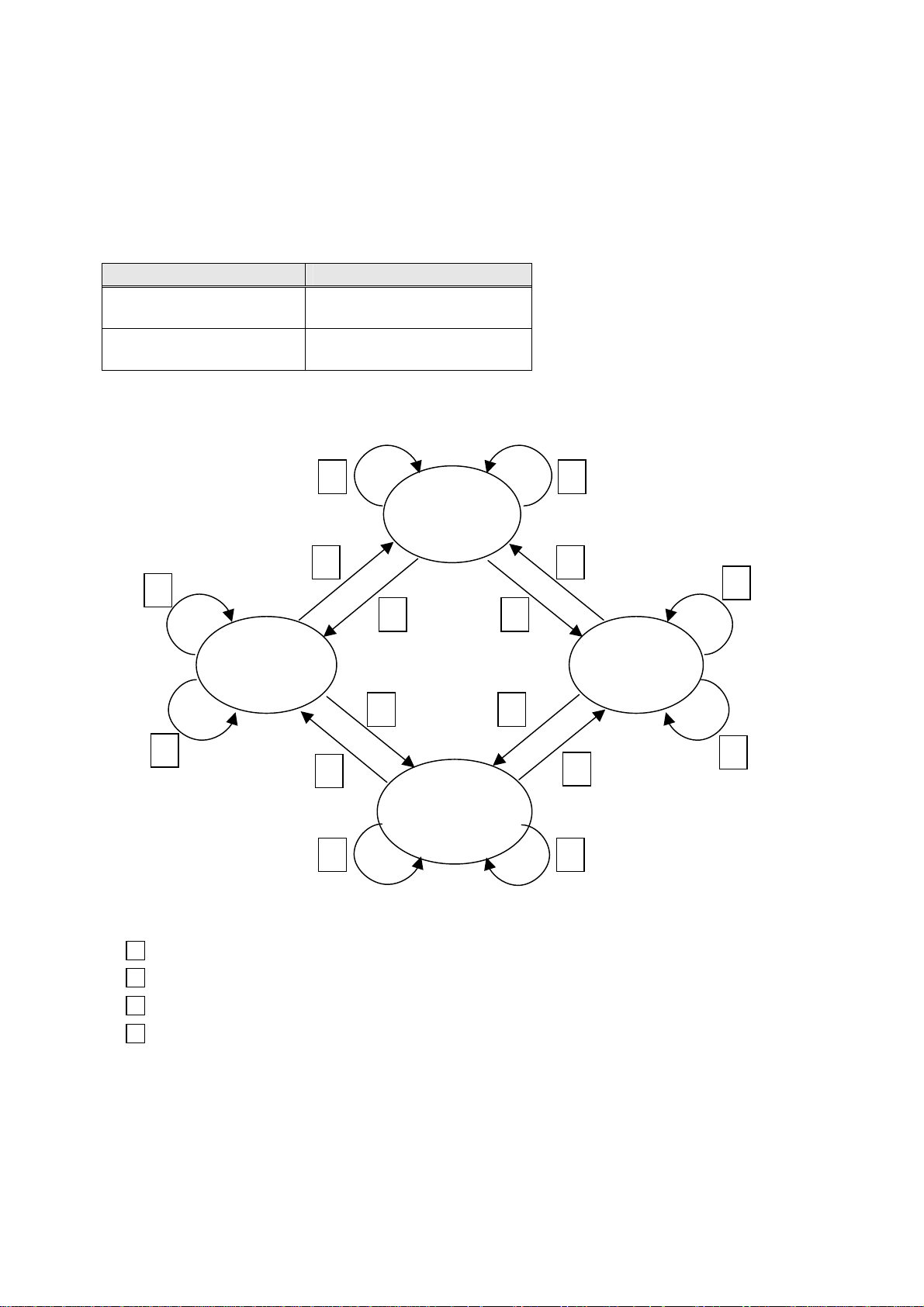
12.2.2. Opening and Closing the Wireless Communications Device
Use the BHT_RF_Open and BHT_RF_OpenEx functions to start up the wireless communication device
and permit wireless communication.
Use the BHT_RF_Close and BHT_RF_CloseEx functions to stop the wireless communication device and
prohibit wireless communication.
Use the BHT_RF_OpenEx (DWORD dwOpt) and BHT_RF_CloseEx (DWORD dwOpt) functions to
perform wireless communication in the following communication formats.
Settable Value Details
COMM_NORMAL
COMM_CONTINUOUS
Wireless communication
open
Wireless communication
continuously open
The following diagram illustrates the wireless communication device status transmission.
2
Wireless
communication
device stopped
4
2
1
1
3
Wireless
communication
open
3
1
4
2
Wireless
communication
continuously
open
4
4
3
Wireless
communication open
& wireless
communication
continuously open
3
2
1
1 BHT_RF_Open() (*1)
2 BHT_RF_Close () (*2)
3 BHT_RF_OpenEx(COMM_CONTINUOUS)
4 BHT_RF_CloseEx(COMM_CONTINUOUS)
(*1) Includes BHT_RF_OpenEx(COMM_NORMAL)
(*1) Includes BHT_RF_OpenEx(COMM_NORMAL)
36
Page 42

12.2.3. Checking Synchronization with the Access Point
When performing data communication with a wireless communication device, use the
BHT_RF_Synchronize function to check whether synchronization with the access point has been
obtained.
The following is a list of possible reasons why it may not be possible to obtain synchronization with the
access point.
(1) The wireless communication device is currently open.
Several seconds are required to obtain synchronization with the access point after opening the
wireless communication device.
Furthermore, when using DHCP, there are times when several tens of seconds are required to
obtain the IP after connecting to the network.
(2) When the wireless device is moved from the current access point to the next access point during
roaming
(3) When the wireless device is moved outside the radio-wave area covered by the access point.
(4) When the wireless device is moved to a location where an obstruction prevents wireless
communication with the access point.
37
Page 43

Chapter 13. Barcode Reading
13.1. Outline
13.1.1. Enable Reading
BHT-700B
The BHT_EnableBar function enables the barcode device to read barcodes. In this function, you may
specify the following barcode types available in the BHT. The BHT can handle one of them or their
combination.
Available Barcode Type Default Setting
Universal product codes
EAN-13 (*1) (JAN-13 (*1))
EAN-8 (JAN-8)
UPC-A (*1), UPC-E
Interleaved 2of5 (ITF)
Standard 2of5 (STF)
Codabar (NW-7)
Code 39
Code 93 No length of read data specified.
Code 128 (EAN-128) (*2) No length of read data specified.
Interleaved 2of5 (ITF)
RSS Nothing specified.
(*1) Reading wide bars
EAN-13 and UPC-A barcodes may be wider than the readable area of the barcode reading window.
Such wider bars can be read by long-distance scanning. Pull the barcode reading window away from
the barcode so that the entire barcode comes into the illumination range.
(*2) Specifying Code 128 makes it possible to read not only Code 128 but also EAN-128.
No national flag specified.
No length of read data specified.
No check digit.
No length of read data specified.
No check digit.
Short format of the start/stop characters supported.
No length of read data specified.
No check digit.
No start/stop character.
No length of read data specified.
No check digit.
No length of read data specified.
No check digit.
38
Page 44

BHT-700Q
The BHT_EnableBar function enables the barcode device to read barcodes. In this function, you may
specify the following barcode types available in the BHT. The BHT can handle one of them or their
combination.
Available Barcode Type Default Setting
2D codes
QR code
PDF417 PDF417, MicroPDF417
MaxiCode Nothing specified
Data Matrix Square Data Matrix, Rectangular Data Matrix
EAN·UCC Composite Nothing specified
1D codes
EAN-13 (*1) (JAN-13( *1))
EAN-8 (JAN-8)
UPC-A *1, UPC-E
Interleaved 2of5 (ITF)
CODABAR (NW-7)
CODE-39
CODE-93 No length of read data specified
CODE-128 (EAN-128)(*2) No length of read data specified
RSS Nothing specified
(*1) Reading wide bars
EAN-13 and UPC-A barcodes may be wider than the readable area of the barcode
reading window.Such wider bars can be read by long-distance scanning. Pull the
barcode reading window away from the barcode so that the entire barcode comes into
the illumination range.
(*2) Specifying Code 128 makes it possible to read not only Code 128 but also EAN-128.
Not specified: Model 1, Model 2, Micro QR code, code version
No split code scanning
Not specified: code no.
No country flag specified
No length of read data specified
No check digit
No length of read data specified
No check digit
No start/stop character
No length of read data specified
No check digit
No start/stop character
No length of read data specified
No check digit
39
Page 45

13.1.2. Specify Options in the BHT_EnableBar Function
You may also specify several options as listed below for each of the barcode types in the
BHT_EnableBar function.
BHT-700B
Barcode type Options
Universal product code Initial (country flag)
add-on code
Interleaved 2of5 (ITF) Length of read data
Check digit
CODABAR (NW-7) Length of read data
Start/stop character
Check digit
Code 39 Length of read data
Check digit
Code 93 Length of read data
Code 128 Length of read data
Standard 2of5(STF) Length of read data
Start/stop character
Check digit
MSI 1-digit check digit
2-digit check digit
RSS Nothing specified.
BHT-700Q
Barcode type Options
2D codes
QR Model
Code version
Split code scanning
PDF417 Code
MaxiCode Nothing specified
Data Matrix Code
Code no.
EAN·UCC Composite Nothing specified
1D codes
Universal product code Initial (country flag)
add-on code
Interleaved 2of5 (ITF) Length of read data
Check digit
CODABAR (NW-7) Length of read data
Start/stop character
Check digit
Code 39 Length of read data
Check digit
Code 93 Length of read data
Code 128 Length of read data
RSS Nothing specified
40
Page 46

13.1.3. Barcode Buffer
The barcode buffer stores the inputted barcode data.
BHT-700B
The barcode buffer will be occupied by one operator entry job and can contain up to 99 characters.
BHT-700Q
The barcode buffer will be occupied by one operator entry job and can contain up to 99 bytes in barcode
or 8,192 bytes in 2D code (1 kanji character equals 2 bytes).
You can check whether the barcode buffer stores code data, by using the BHT_GetBarNum function. To
read barcode data stored in the barcode buffer, use the BHT_ReadBar/BHT_ReadBarEx function.
41
Page 47

13.2. Programming
13.2.1. Code Mark
The BHT_GetBarType function allows you to check the code mark (denoting the code type) and the
length of the inputted barcode data.
13.2.2. Multiple Code Reading
You may activate the multiple code reading feature which reads more than one code type while
automatically identifying them. To do it, you should designate desired code types in the read code
parameter of the BHT_EnableBar function.
13.2.3. Read Mode of the Trigger Switch
The trigger switch function is assigned to the [SCAN] key and the magic key M3 by default. You may
assign the trigger switch function to other keys by using the BHT_SysSettingDW function.
You may select the read mode of the trigger switch by using the BHT_EnableBar function as listed below.
Read Mode BHT_EnableBar Function
Auto-off Mode
Momentary Switching Mode
Alternate Switching Mode
Continuous Reading Mode
To check whether the trigger switch is pressed or not, use the BHT_WaitEvent function as shown below.
BHT_WaitEvent (1, BHT_EVT_MASK_TRGDOWN, 0, &dwSignaledEvent);
if ( (dwSignaledEvent & BHT_EVT_MASK_TRGDOWN) != 0 ) {
printf("Trigger switch pressed ");
}
13.2.4. Generating a Check Digit of Barcode Data
Specifying a check digit in the BHT_EnableBar function makes the Interpreter automatically check
barcodes. If necessary, you may use the BHT_GetBarChkdgt function for generating a check digit of
barcode data.
BHT_EnableBar (TEXT ("F…
BHT_EnableBar (TEXT ("M…
BHT_EnableBar (TEXT ("A…
BHT_EnableBar (TEXT ("C…
42
Page 48

13.2.5. Controlling the Indicator LED and Beeper/Vibrator as a Confirmation of Successful Reading
By using the BHT_EnableBar function, you can control:
- whether the indicator LED should light in blue or not (Default: Light in blue)
- whether the beeper should beep or not (Default: No beep)
when a barcode is read successfully. For detailed specifications, refer to the description for the
BHT_EnableBar function.
It is also possible to operate the vibrator as a confirmation of successful reading instead, by using the
BHT_SetSysSettingDW (BHT_BEEP_VIB_SELECT, VIB_SELECT) function.
(1) Controlling the indicator LED
If you have activated the indicator LED (blue) in the BHT_EnableBar function, an application cannot
control the LED.
If you have deactivated the indicator LED (blue) in the BHT_EnableBar function, an application can
control the LED even when the barcode device file is opened.
This way, you can control the indicator LED, enabling that:
• a user program can check the value of a scanned barcode and turn on the indicator LED in blue
when the barcode has been read successfully.
• a user program can turn on the indicator LED in red the moment the barcode has been read.
(2) Controlling the beeper and vibrator
If you have activated the beeper in the BHT_EnableBar function, the BHT will beep when it reads a
barcode successfully.
You may select beeping only, vibrating only, or beeping & vibrating by setting on the system menu
(BhtShell.exe) or by setting the output port in the BHT_SetSysSettingDW(BHT_BEEP_VIB_SELECT,...).
This feature is used to sound the beeper or operate the vibrator the moment the BHT reads a barcode
successfully.
13.2.6. Reading Split QR Codes (Only for BHT-700Q)
The QR Code symbology can split data into a maximum of 16 blocks and encodes each of them into a
split code image. When those split code images are scanned, the splitter system restores them into the
oritinal data string in any of the following three modes--edit mode, batch edit mode, and non-edit mode.
These modes can be specified by BHT_EnableBar as follows:
Split code scanning mode BHT_EnableBar function
Edit mode BHT_EnableBar(…, TEXT("Q : E"))
Batch edit mode BHT_EnableBar(…, TEXT("Q : B"))
Non-edit mode BHT_EnableBar(…, TEXT("Q : C"))
In edit mode, after completion of reading all split code images, the splitter system stores the read data
into the code buffer. In batch edit mode, when all split code images that fall within the scanning range are
read, the splitter system stores the read data into the code buffer. In non-edit mode, each time a single
split code image is read, the splitter system stores the read data into the code buffer.
The code type which is acquired by the BHT_GetBarType function and the BHT_GetBarInfo function is
“Q” in edit mode and batch edit mode or “S” in non-edit mode.
43
Page 49

NOTE: In the Point Scan mode, scanning split codes in batch edit mode is disabled. (For details about
the Point Scan mode, refer to the “BHT-700BB/700BWB/700BWBG-CE User's Manual” or "BHT700QWBG-CE User's Manual").
13.3. Barcode Reading Using the Virtual COM Port
13.3.1. Outline
Barcode reading using the virtual COM port is supported on the BHT-700 series.
For greater convenience, this function is available for use in conjunction with kbifCE. For more
information on kbifCE, see the kbifCE user's guide (available for download on the DENSOWAVE QBNet
website).
Using this function it is possible to obtain reading data as if it were being received through a COM port.
For applications, it is equivalent to a reader being connected to the communication port (COMx). Using
COM, barcode reading data can be used by multiple applications.
13.3.2. Programming
Port number 5 is allocated to the virtual COM port used for barcode reading.
Barcode reading mode and the types of barcodes that are allowed to be read are designated by the
kbifCE.
A comparison of the functions of Win32 API when using a general COM port and a virtual COM port for
barcode use is as follows:
Win32 API General COM Virtual COM used for reading
CreateFile Open COM port ←
CloseHandle Close COM port ←
ReadFile Read received data Read data
GetCommMask Obtain type of wait event ←
SetCommMask Set type of wait event ←
Treat completed reading event as
receiving event.Non-reading events
invalid.(*1)
GetCommTimeouts Obtain timeout value ←
SetCommTimeouts Set timeout value ←
Non-receiver side timeouts invalid.(*1)
WaitCommEvent Wait for event ←
Non-receiving events invalid.
(*1) An error will not occur.
The following functions are not supported. If operation is attempted, no function will be executed.
List of functions not yet supported
WriteFile GetCommModemStatus SetCommBreak
ClearCommBreak GetCommProperties SetCommState
ClearCommError GetCommState SetupComm
EscapeCommFunction PurgeComm TransmitComm
13.3.3. How to Use
Start up kbifCE and set the destination for the virtual COM port (for further details see the kbifCE user's
guide).
44
Page 50
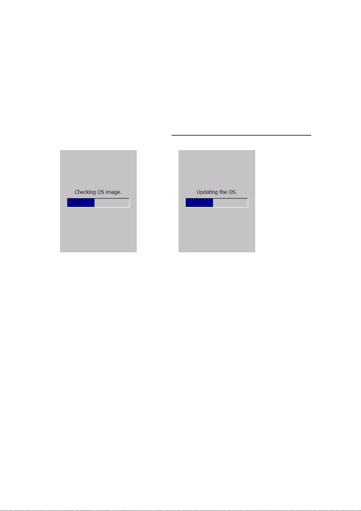
Chapter 14. Updating OS
The OS can be updated (version update) using the following method when running Windows CE.
(1) Copy the OS image file to an arbitrary folder.
(2) Execute the BHT_SystemModify function.
For the 1st argument, specify the absolute path to the folder in which the OS image file was stored,
and for the 2nd argument, specify whether to turn OFF the power or perform a cold boot after
updating the OS.
(For example) Update OS image file named “_B7BWDW0.SY3” stored in “\temp\” folder and
perform a cold boot after updating OS
DWORD dwRtn;
dwRtn = BHT_SystemModify(TEXT(
(3) Following display is shown during updating OS.
\\Temp\\_B7BWDW0.SY3), SYSMDFY_REBOOT);
(checking OS image) (writing OS image)
(4) After the OS has been successfully updated, the BHT-700 power will either be turned OFF or will
cold boot depending on the setting made for the 2nd argument.
45
Page 51

Chapter 15. System Functions
System functions are used when setting or acquiring system values or when acquiring device information.
Function Used to:
BHT_SetSysSettingDW
BHT_GetSysSettingDW
BHT_SetSysSettingWCS
BHT_GetSysSettingWCS
BHT_GetDeviceInfo
Write system parameter values (DWORD).
Read system parameter values (DWORD).
Write system parameter values (character string).
Read system parameter values (character string).
Device information acquisition
46
Page 52
15.1. If a System Parameter Value is DWORD
BHT_SetSysSettingDW
Description
Write system parameter values.
Syntax
DWORD BHT_SetSysSettingDW (
DWORD dwCtrlCode ,
DWORD dwSysParam )
Parameters
dwCtrlCode
[in] Control code
dwSysParam
[in] Parameter value
Return value
Error code Meaning
ERROR_SUCCESS Successful completion
ERROR_INVALID_PARAMETER Invalid parameter
ERROR_GEN_FAILURE Not supported
47
Page 53
BHT_GetSysSettingDW
Description
Read system parameter values.
Syntax
DWORD BHT_GetSysSettingDW (
DWORD dwCtrlCode ,
DWORD* pdwSysParam )
Parameters
dwCtrlCode
[in] Control code
pdwSysParam
[out] Address for storing the parameter value
Return value
Error code Meaning
ERROR_SUCCESS Successful completion
ERROR_GEN_FAILURE Not supported
ERROR_INVALID_PARAMETER No storage address specified
48
Page 54

15.2. If a System Parameter Value is a Character String
BHT_SetSysSettingWCS
Description
Write system parameter values.
Syntax
DWORD BHT_SetSysSettingWCS (
DWORD dwCtrlCode ,
TCHAR* pwchSysParam ,
DWORD dwLen )
Parameters
dwCtrlCode
[in] Control code
pwchSysParam
[in] Heading address of the storage buffer for a string written
dwLen
[in] String length
Return value
Error code Meaning
ERROR_SUCCESS Successful completion
ERROR_INVALID_PARAMETER Invalid parameter
ERROR_GEN_FAILURE Not supported
49
Page 55

BHT_GetSysSettingWCS
Description
Read system parameter values.
Syntax
DWORD BHT_GetSysSettingWCS (
DWORD dwCtrlCode ,
TCHAR* pwchSysParam ,
DWORD dwLen ,
DWORD* pdwLenReturned )
Parameters
dwCtrlCode
[in] Control code
pwchSysParam
[out] Heading address of the storage buffer for a string read
dwLen
[in] String length
pdwLenReturned
[out] Length of the string read out
Return value
Error code Meaning
ERROR_SUCCESS Successful completion
ERROR_GEN_FAILURE Not supported
ERROR_INVALID_PARAMETER No storage address specified
50
Page 56

15.3. System Parameter Values That Can be Set/Obtained
Parameter name Type R/W Control code Parameter value Default
System information related
System version
(4 characters)
Total RAM size
(bytes)(*1)
Total ROM size
(bytes) (*1)
Model name
(8 characters)
Product number
(16 characters)
Serial number
(6 characters)
Waiting time to switch to
standby mode (in units
of 100 ms)
Waiting time to auto
power OFF when
powered by battery
(sec.)
Waiting time to auto
power OFF when placed
on CU (sec.)
CPU clock (*2) DW R/W BHT_PM
Auto Power OFF
permitted when wireless
connection open
Rumble device DW R/W BHT_BEEP_VIB
Beeper volume DW R/W BHT_BEEP_VIB
Key click volume DW R/W BHT_BEEP_VIB_KEY 0: OFF
Screen tap volume DW R/W BHT_BEEP_VIB_TAP 0: OFF
Trigger switch clicks(*3) DW R/W BHT_BEEP_VIB
WCS R BHT_SYS_OS
DW R BHT_SYS
DW R BHT_SYS
WCS R BHT_SYS
WCS R BHT_SYS
WCS R/W BHT_SYS
DW R/W BHT_PM_STBYTIME 0: Disable
DW R/W BHT_PM
DW R/W BHT_PM
DW R/W BHT_PM_SUSPEND
_VERSION
_RAMSIZE
_ROMSIZE
_MACHINE_NAME
_MACHINE_NUMBER
_SERIAL_NUMBER
Power management related
_BATTPOWEROFF
_EXTPOWEROFF
_CPU_CLOCK
_RF
Beeper and vibrator related
_SELECT
_VOLUME
_TRGKEY
6-digit number Lower 6 characters in
1 to 255
0: Disable
1 to 0xFFFFFFFF
0: Disable
1 to 0xFFFFFFFF
CPU_CLK_NORMAL
: Regular speed
CPU_CLK_FAST
: High speed
SUSPEND_DISABLE
: Suspend prohibeted
SUSPEND_ENABLE
: Suspend permitted
BEEP_SELECT
: Beeper
VIB_SELECT
: Vibrator
(BEEP_SELECT
| VIB_SELECT)
: Beeper and vibrator
0:OFF
1 (lowest)
to 5 (highest)
1: Soft
2: Loud
1: Soft
2: Loud
CLICK_SOUND_OFF
: Prohibit
CLICK_SOUND_ON
: Allow
- - -
- - -
- - -
- - -
- - -
the code printed on the
back of the BHT
10 (1 sec) Immediately
180 (3 min) Immediately
0 Immediately
CPU_CLK_NORMAL When warm-
SUSPEND_ENABLE Immediately
BEEP_SELECT first sound
5 first sound
2 first sound
2 first sound
CLICK_SOUND_OFF first sound
Validating
timing
Immediately
after setting
after setting
after setting
after setting
booting after
setting
after setting
after setting
after setting
after setting
after setting
after setting
51
Page 57

Parameter name Type R/W Control code Parameter value Default
Backlight related
Backlight ON-duration
(sec.)
(When battery- driven)
Backlight ON-duration
(sec.)
(When placed on the
CU)
Control key DW R/W BHT_BACKLIGHT
Backlight brightness
level
Backlight power saving
mode
Illumination device
selection when backlight
illumination specified
from API
Key backlight
illumination trigger
Re-read prevention
enabled time (in units of
100 ms)
Black-and-white inverted
label
reading function
Decode level DW R/W BHT_BAR_DCD
Min. number of digits to
be read for ITF
Min. number of digits to
be read for STF (*5)
Min. number of digits to
be read for Codabar
(CODABAR)
DW R/W BHT_BACKLIGHT
_BATT_TIME
DW R/W BHT_BACKLIGHT
_AC_TIME
_KEY
DW R/W BHT_BACKLIGHT
_BRIGHTNESS
DW R/W BHT_BACKLIGHT
_POWERSAVE
DW R/W BHT_BACKLIGHT
_DEVICE
DW R/W BHT_BACKLIGHT
_FACTOR
Barcode reading related
DW R/W BHT_BAR_CRTIME 0 to 255 (*4) 10 Immediately
DW R/W BHT_BAR_INVERT BHT-700B
_LEVEL
DW R/W BHT_BAR_MINDGT
_ITF
DW R/W BHT_BAR_MINDGT
_STF
DW R/W BHT_BAR_MINDGT
_NW7
0 - 255
0: Backlight OFF
255: Backlight continuously
ON
0 - 255
0: Backlight OFF
255: Backlight continuously
ON
Key number 0x10203
0: OFF
1: Dark – 3: Bright
0: OFF
1: Dim
0: None
LIGHTING_LCD
:LCD
LIGHTING_KEY
:KEY
LIGHTING_LCD |
LIGHTING_KEY
: Both LCD and key
0: Always OFF
BHT_BLT_KEY_FACTOR_
KEY
: Key-press
BHT_BLT_KEY_FACTOR_
KEYTAP
: Both key-press and tap
0: Prohibit
1: Allow (automatic)
BHT-700Q
0: Disable
1. Enable (black-and-white
inversion only)
2: Allow (automatic)
1 to 9 4 When the
2 to 20 4 When the
1 to 20 3 When the
3 to 20 4 When the
Validating
timing
3 When backlight
60 When backlight
([SF]+[M3])
3 When the
1 When backlight
LIGHTING_LCD Immediately
BHT_BLT_KEY_
FACTOR_KEY
0 Immediately
illumination timer
is next reset
illumination timer
is next reset
Immediately
after setting
backlight is next
turned ON
illumination
status is set to
power saving
mode first after
setting
after setting,
when
BHT_SetBltStatu
s next called
Immediately
after setting, first
tap or key press
when
"BHT_BLT_KEY
_FACTOR_KEY"
or
"BHT_BLT_KEY
_FACTOR_KEY
TAP"
after setting
after setting
barcode device
is opened first
after setting
barcode device
is opened first
after setting
barcode device
is opened first
after setting
barcode device
is opened first
after setting
52
Page 58

Scanning range marker
(*6)
DW R/W BHT_BAR_MARKER MARKER_NORMAL
: Normal mode
MARKER_AHEAD
Maker ahead
:
MARKER_DISABLE
: Fixed to OFF
MARKER
_NORMAL
Immediately
after setting
53
Page 59

Parameter name Type R/W Control code Parameter value Default
Front-back inverted
reading (*6)
Scan mode (*6) DW R/W BHT_BAR_SCAN
Option data (*6) DW R/W BHT_BAR_OPTION
Ilumination mode (*6) DW R/W BHT_BAR_LIGHT_MO
Shift key mode DW R/W BHT_KEY_SHIFT
Assignment to M1 key DW R/W BHT_KEY
Assignment to M2 key DW R/W BHT_KEY
Assignment to M3 key DW R/W BHT_KEY
Key entry mode DW R/W BHT_KEY
Enable/disable alphabet
entry switching key
Function mode DW R/W BHT_KEY
Effective held-down time
of power key for
suspending
(in units of 100 ms)
Keypad type DW R BHT_KEYBOARD
DW R/W BHT_BAR_REVERSE 0: Disable
_MODE
_DATA
DE
Keyboard related
_MODE
_M1_MODE
_M2_MODE
_M3_MODE
_INPUT_METHOD
DW R/W BHT_DISABLE
_KEYMODE
_CHANGE_KEY
_FUNCTION
DW R/W BHT_PWRDOWN
_KEY_WAIT_TIME
_TYPE
1: Enable
SCAN_MODE_NORMAL
: Normal mode
SCAN_MODE_POINT
: Point scan mode
SCAN_MODE_1D
:Barcode reader mode
0: There is option data.
1: No option data
0:AUTO
1: Always ON
2: Always OFF
KEY_NON_LOCK
: Non-lock
KEY_ONE_TIME
: Onetime lock
MAGIC_FUNC_NONE
: Ignore the depressed key
MAGIC_FUNC_ENTER
: Treat as ENT key
MAGIC_FUNC_TRG
: Treat as trigger switch
MAGIC_FUNC_SHIFT
: Treat as SF key
MAGIC_FUNC_ALT
: Treat as ALT key
MAGIC_FUNC_CTRL
: Treat as CTRL key
MAGIC_FUNC_BLT
: Treat as bacjlight function
on/off key
MAGIC_FUNC_TAB
: Treat as TAB key
MAGIC_FUNC_CLEAR
: Treat as CLEAR key
MAGIC_FUNC_USERDEF
: User-defined code
INPUT_METHOD
_NUMERIC
: Numeric entry mode
INPUT_METHOD
_ALPHABET2
: Alphabet entry mode 2
ENABLE_KEY
_TOCHANGE
_ALPHABET
: Enable
DISABLE_KEY
_TOCHANGE
_ALPHABET
: Disable
KEY_FUNCTION_ON
: Function mode
KEY_FUNCTION_OFF
: Non-function mode
1 - 255 5 Immediately after
KEYBOARD_TYPE1
: 27-key pad
KEYBOARD_TYPE2
/ KEYBOARD_TYPE2P
: 42-key pad
Validating
timing
0 Immediately
SCAN_MODE_
NORMAL
0 Immediately
1 Immediately
KEY_NON
_LOCK
MAGIC_FUNC
_TAB
MAGIC_FUNC
_NONE
MAGIC_FUNC
_TRG
27-key type:
INPUT_METHO
D_NUMERIC
42-key type:
INPUT_METHO
D_ALPHABET
ENABLE_KEY
_TOCHANGE
_ALPHABET
KEY
_FUNCTION
_OFF
- -
after setting
When the
barcode device
is opened first
after setting
after setting
after setting
Immediately
after setting
Immediately after
setting
Immediately after
setting
Immediately after
setting
Immediately after
setting
Immediately after
setting
Immediately after
setting
setting
54
Page 60

Parameter name Type R/W Control code Parameter value Default Validating timing
Status indicator related
Battery voltage level
icon
Software keyboard
icon
Keypad shift icon DW R/W BHT_ICON
Alphabet input icon
(27-key type only)
Wireless
communication state
icon
Standby state icon DW R/W BHT_ICON
Function mode state
icon
Numeric entry mode
icon (42-key type only)
Bluetooth power status DW R/W BHT_ICON
ActiveSync automatic
connection
DW R/W BHT_ICON
_BATTERY
DW R/W BHT_ICON_SIP 0: Hide
_SHIFTKEY
DW R/W BHT_ICON
_IN_ALPHA
DW R/W BHT_ICON
_RADIO_INTEN
SE
_STANDBY
DW R/W BHT_ICON_FU
NC
DW R/W BHT_ICON_NU
MERIC
_BLUETOOTH
DW R/W BHT_ACTSYNC
_AUTOCNCT
0: Hide
1: Display
1: Display
0: Hide
1: Display
0: Hide
1: Display
0: Hide
1: Display
0: Hide
1: Display
0: Hide
1: Display
0: Hide
1: Display
0: Hide
1: Display
Communication related
ACTSYNC_AUTOCNCT
_DISABLE
: Prohibited
ACTSYNC_AUTOCNCT
_USB
: Only USB allowed
1 Immediately after setting
1 Immediately after setting
1 The icon appears when the
1 The icon appears when the
1 The icon appears when the
0 The icon appears when the
1 The icon appears when the
1 The icon appears when the
0 Immediately after setting
ACTSYNC
_AUTOCNCT
_USB
keypad is shifted first after
this parameter is set to "1."
(If the keypad has been
shifted, the icon appears
immediately.)
It disappears when the shift
is released first after this
parameter is set to "0."
alphabet input function is
activated first after this
parameter is set to "1."
It disappears when the
alphabet input function is
deactivated first after this
parameter is set to "0."
wireless device is opened
first after this parameter is
set to "1." (If the wireless
device has been opened, the
icon appears immediately.)
It disappears immediately
after this parameter is set to
"0."
CPU comes to be on
standby first after this
parameter is set to "1." It
disappears immediately after
this parameter is set to "0."
function mode is activated
first after this parameter is
set to "1."
It disappears when the
function mode is deactivated
first after this parameter is
set to "0."
numeric entry mode is
activated first after this
parameter is set to "1." It
disappears when the
numeric entry mode is
deactivated first after this
parameter is set to "0."
After setting, when the USB
cable or RS232C cable is
first inserted, or when the
CU421 is installed.
55
Page 61
Parameter name Type R/W Control code Parameter value Default Validating timing
Display related
Screen rotation DW R/W BHT_DISP
Screen rotation control
key
Touch screen disabling DW R/W BHT_TOUCH
Bluetooth device initial
power status
Voice output from
receiver
DW R/W BHT_DISP
DW R/W BHT_BT_INITIAL_
DW R/W BHT_AUDIO_OUT
_ROTATION
_ROTATION_KEY
_DEVICE
POWER_STATUS
_RCV
Touch screen related
DISP_ROTATION_0
: 0°
DISP_ROTATION_90
: 90°
DISP_ROTATION_180
: 180°
DISP_ROTATION_270
: 270°
Key no. None Immediately
TOUCH_ENABLE
: Enable
TOUCH_DISABLE
: Disable
Bluetooth related
BHT_BT_POWER_OFF
: Power OFF
BHT_BT_POWER_ON
: Power ON
Audio related
BHT_AUDIO_OUT_RCV
_DISABLE
: Disable
BHT_AUDIO_OUT_RCV
_ENABLE
: Enable
DISP
_ROTATION_0
TOUCH_ENABLE Immediately
BHT_BT
_POWER_OFF
BHT_AUDIO_OUT_
RCV_DISABLE
Immediately
after setting
after setting
after setting
Immediately
after setting
Immediately
after setting
(*1) The RAM or ROM size obtained indicates the capacity of the memory mounted on the BHT. To obtain t
he size of the memory area allowed for the user to use, use GetDiskFreeSpaceEx.
(*2) If the CPU clock is set to high speed, the processing speed becomes higher but the power
consumption Increases.
(*3) This parameter controls the on/off of the click sound of the magic key which the trigger switch is
assigned to. If it is set to ON, pressing the magic key clicks at the volume specified by the "Key clock
volume."
(*4) If this parameter is set to "0," the BHT no longer reads the same barcode in succession.
(*5) Only for BHT-700B
(*6) Only for BHT-700Q
56
Page 62
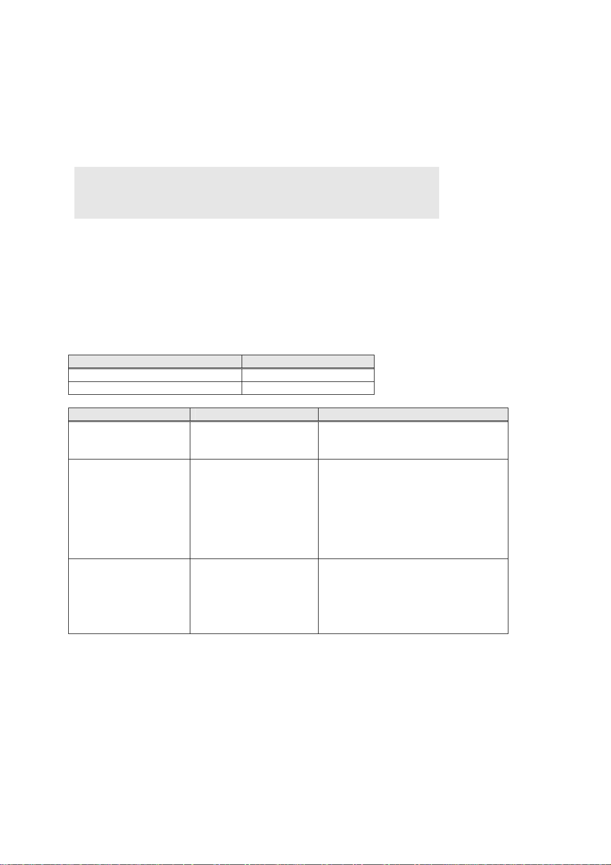
15.4. Device Information Acquisition
BHT_GetDeviceInfo
Description
Acquires the mounted device information.
Syntax
DWORD BHT_GetDeviceInfo(
DWORD dwDevice,
DWORD* pdwDevInfo,
LPVOID pvExtInfo )
Parameters
dwDevice
[in] Type of the device for which information is being acquired
pdwDevInfo
[out] Device information storage location
pdwDevInfo
[out] Extension information storage location
Return Value
Error Code Meaning
ERROR_SUCCESS Successful completion
ERROR_INVALID_PARAMETER Parameter error
Device Type dwDevice *pdwDevInfo
Read device BHT_DEV_SCANNER Either of the following :
SCANNER_1DIM :1D
SCANNER_2DIM :2D
Communication device BHT_DEV_COM The following combinations:
COMDEV_SERIAL :RS-232C
COMDEV_INFRARED :Infrared Port
COMDEV_USB :USB
COMDEV_RF :Wireless
COMDEV_BLUETOOTH
:Bluetooth
COMDEV_GPRS :GPRS
ActiveSync device BHT_DEV_ACTSYNC The following combinations:
ACTSYNC_SERIAL :RS-232C
ACTSYNC_INFRARED
:Infrared Port
ACTSYNC_USB :USB
ACTSYNC_RF :Wireless
57
Page 63

Chapter 16. Device Control Functions
The device control functions listed below control the devices (barcode reading device, backlight, battery,
indicator LED, etc.) dedicated to the BHT.
Function Used to:
BHT_EnableBar
BHT_DisableBar
BHT_ReadBar
BHT_ReadBarEx
BHT_GetBarType
BHT_GetBarNum
BHT_GetBarInfo
BHT_GetBarChkDgt
BHT_BAR_SetDecodeOptions
BHT_BAR_GetDecodeOptions
BHT_SetBltStatus
BHT_GetBltStatus
BHT_GetPowerStatus
BHT_GetPowerStatus2nd
BHT_GetNLedStatus
BHT_SetNLedStatus
BHT_GetNLedStatusEx
BHT_SetNLedOn
BHT_SetNLedOff
BHT_StartBeep
BHT_StartBeeperOnly
BHT_StartVibrationOnly
Open the barcode device file to enable barcode reading. This function
specifies the read mode and readable barcode types.
Close the barcode device file to disable barcode reading.
Read out data read from the barcode buffer.
Read out data from the barcode buffer and encodes it into the specified
data format.
Read the barcode type and the number of digits of a barcode read most
recently.
Read the number of digits of the barcode remaining in the barcode buffer.
Read the information on the code read most recently.
Calculate a check digit (CD) of the barcode data according to the
calculation method specified by dwCDType.
Sets the editing function setting value for the decoded result.
Acquires the editing function setting value for the decoded result.
Control the backlight.
Read the backlight status.
Read information about the battery loaded in the BHT body.
Read information about the battery loaded in the grip.
Read the status of the indicator LED.
Control the indicator LED.
Read the status of the indicator LED and synchronization LED.
Turn on the indicator LED and/or synchronization LED.
Turn off the indicator LED and/or synchronization LED.
Drive the beeper/vibrator.
Drive the beeper.
Drive the vibrator.
58
Page 64

BHT_RF_Open
BHT_RF_OpenEx
BHT_RF_Close
BHT_RF_CloseEx
BHT_RF_Synchronize
BHT_RF_GetParamInt
BHT_RF_SetParamInt
BHT_RF_GetParamStr
BHT_RF_SetParamStr
BHT_RF_GetInfoInt
BHT_RF_GetInfoStr
BHT_RF_IoControl
BHT_RF_GetSiteSurvey
BHT_SystemModify
BHT_WaitEvent
BHT_WaitStandbyEvent
BHT_ShutdownSystem
BHT_RegStore
Function Used to:
Open the wireless LAN device and enable wireless communication.
Set the communication format, open the wireless LAN device and enable
wireless communication.
Close the wireless LAN device and disable wireless communication.
Close the wireless LAN device for the set format and disable wireless
communication.
Get the association status.
Read integer from the wireless communications parameter.
Write integer to the wireless communications parameter.
Read string from the wireless communications parameter.
Write string to the wireless communications parameter.
Read integer from the communications parameter.
Read string to the communications parameter.
Perform operation for the profile and certificate etc.
Get quality of the communications link.
Update the BHT OS.
Make the system wait until the specified event or timeout occurs.
Make the system wait until the specified event occurs.
Turn off the BHT and boot it according to the specified mode.
Turn off the BHT and boot it according to the specified mode.
59
Page 65

16.1. Barcode API
BHT_EnableBar
Description
Open the barcode device file to enable barcode reading.
This function specifies the read mode and readable barcode types. Up to eight barcode types can be
specified.
Syntax
DWORD BHT_EnableBar (
TCHAR* pwchRdMode ,
TCHAR* pwchCdParam )
Parameters
pwchRdMode
[in] Heading address of the storage buffer for a character string specifying the read mode,
beeper/vibrator on/off, and LED on/off
pwchCdParam
[in] Heading address of the storage buffer for a character string specifying barcode types to be read
Return value
Error code Meaning
ERROR_SUCCESS Successful completion
ERROR_TOO_MANY_OPEN_FILES Barcode device file already opened.
ERROR_INVALID_PARAMETER Parameter error. More than 24 barcode types are specified.
Comment:
Up to 24 barcode types can be specified.
BHT-700Q:
The maximum code version for QR Code, the maximum code number for Data Matrix, and the
maximum number of digits for barcodes are limited by the readable range.
60
Page 66

■ Readmode
The BHT supports four read modes--the momentary switching mode, the auto-off mode, the alternate
switching mode, and the continuous reading mode, which can be selected by specifying M, F, A, and C to
readmode, respectively.
□ Momentary switching mode (M)
Only when you hold down the trigger switch, the illumination LED lights and the BHT can read a
barcode.
Until the entered barcode data is read out from the barcode buffer, pressing the trigger switch cannot
turn on the illumination LED so that the BHT cannot read the next barcode.
[Ex]
BHT_EnableBar (TEXT ("M"), TEXT ("A, I:4-99, M:1-99, N:3-99, L:1-99, K:1-99, H:1-99" ) )
□ Auto-off mode (F)
If you press the trigger switch, the illumination LED comes on. When you release the switch or when
the BHT completes barcode reading, then the illumination LED will go off. Holding down the trigger
switch lights the illumination LED for a maximum of 5 seconds.
While the illumination LED is on, the BHT can read a barcode until a barcode is read successfully or
the barcode devices file becomes closed.
If the illumination LED goes off after 5 seconds from when you press the trigger switch, it is necessary
to press the trigger switch again for reading a barcode.
Once a barcode is read successfully, pressing the trigger switch cannot turn on the illumination LED
and the BHT cannot read the next barcode as long as the entered barcode data is not read out from
the barcode buffer.
[Ex]
BHT_EnableBar (TEXT ("F"), TEXT ("A, I:4-99, M:1-99, N:3-99, L:1-99, K:1-99, H:1-99" ) )
□ Alternate switching mode (A)
If you press the trigger switch, the illumination LED comes on. Even if you release the switch, the
illumination LED remains on until the barcode device file becomes closed or you press that switch
again. While the illumination LED is on, the BHT can read a barcode.
Pressing the trigger switch toggles the illumination LED on and off.
Once a barcode is read successfully, pressing the trigger switch turns on the illumination LED but the
BHT cannot read the next barcode as long as the entered barcode data is not read out from the
barcode buffer.
[Ex]
BHT_EnableBar (TEXT("A"), TEXT("A,I:4-99,M:1-99,N:3-99,L:1-99,K:1-99,H:1-99"))
□ Continuous reading mode (C)
If this mode is specified, the BHT turns on the illumination LED and keeps it on until the barcode device
file becomes closed, irrespective of the trigger switch.
While the illumination LED is on, the BHT can read a barcode.
Once a barcode is read successfully, the BHT cannot read the next barcode as long as the entered
barcode data is not read out from the barcode buffer.
[Ex]
BHT_EnableBar (TEXT("C"), TEXT("A,I:4-99,M:1-99,N:3-99,L:1-99,K:1-99,H:1-99"))
In the momentary switching mode, alternate switching mode, or continuous reading mode, after you
read a low-quality barcode which needs more than one second to be read, keeping applying the
barcode reading window to that barcode may re-read the same barcode in succession at intervals of
one second or more.
61
Page 67

■ Beepercontrol and LEDcontrol
This function can control the beeper and the indicator LED to activate or deactivate each of them when a
barcode is read successfully. This function may also control the vibrator with beepercontrol.
- You should describe parameters of readmode, beepercontrol, and LEDcontrol without any space
inbetween.
- You should describe readmode, beepercontrol, and LEDcontrol in this sequence.
- Specifying B to beepercontrol allows you to select beeping only, vibrating only, or beeping & vibrating
according to the setting made on the BEEP/VIBRATOR menu in System Menu or the setting made
with the system function.
- Specifying L to LEDcontrol will not turn on the indicator LED.
[Ex] To sound the beeper (or operate the vibrator) when a barcode is read successfully:
BHT_EnableBar (TEXT("FB"), TEXT("A,I:4-99,M:1-99,N:3-99, L:1-99,K:1-99,H:1-99"))
[Ex] To deactivate the indicator LED when a barcode is read successfully:
BHT_EnableBar (TEXT ("FL"), TEXT ("A, I:4-99, M:1-99, N:3-99, L:1-99, K:1-99, H:1-99" ) )
■ Readcode
BHT-700B
The BHT supports the universal product codes, Interleaved 2of5 (ITF), Standard 2of5 (STF), Codabar
(NW-7), Code 39, Code 93, and Code 128, MSI, and RSS. The BHT can read also EAN-128 if Code 128
is specified.
□ Universal product codes (A)
Syntax
st
A [;[code][1
character [2nd character]][supplemental]]
where code is A, B, or C specifying the following:
code Barcode type
A EAN-13 (JAN-13), UPC-A
B EAN-8 (JAN-8)
C UPC-E
If code is omitted, the default is all of the universal product codes.
1stchara and 2ndchara are flag characters representing a country code and should be numerals from 0
to 9. If a question mark (?) is specified to 1stchara or 2ndchara, it acts as a wild card.
“supplemental” refers to the reading of an add-on code. Specifying an S for add-on enables the BHT to
read also barcodes with an add-on code.
[Ex] To enable the BHT to scan EAN-13 with 1stchara "4," 2ndchara "9" and add-on code
BHT_EnableBar(TEXT("FL"), TEXT("A:49S"))
[Ex] To enable the BHT to scan EAN-13 and EAN-8 only
BHT_EnableBar(TEXT("FL"), TEXT("A:A,A:B"))
62
Page 68

□ Interleaved 2 of 5 (ITF) (I)
Syntax
I[:[mini.no.digits[-max.no.digits]][CD]]
where
mini.no.digits and max.no.digits are the minimum and maximum numbers of digits for barcodes to be
read by the BHT, respectively.They should be a numeral from 2 to 99 and satisfy the following
conditions:
mini.no.digits ≤ max.no.digits
If both of mini.no.digits and max.no.digits are omitted, then the default reading range is from the
minimum number of digits specified in the system menu (BhtShell.exe) up to 99 digits.
If only max.no.digits is omitted, the BHT can only read the number of digits specified by mini.no.digits.
CD is a check digit. Specifying a C to CD makes the Interpreter check barcodes with MOD-10. The
check digit is included in the number of digits.
[Ex] To enable the BHT to scan ITF with min.no.digits 6, max.no.digits 10, and MOD-10
BHT_EnableBar(TEXT("FL"), TEXT("I:6-10C"))
[Ex] To enable the BHT to scan ITF with min.no.digits 6 and max.no.digits 10 or with min.no.digits 20
and max.no.digits 40
BHT_EnableBar(TEXT("FL"),TEXT("I:6-10,I:20-40"))
63
Page 69

□ CODABAR (NW-7) (N)
Syntax
N[:[mini.no.digits[-max.no.digits]][startstop][CD]]
Where
mini.no.digits and max.no.digits are the minimum and maximum numbers of digits for barcodes to be
read by the BHT, respectively.They should be a numeral from 3 to 99 and satisfy the following
condition:
mini.no.digits ≤ max.no.digits
If both of mini.no.digits and max.no.digits are omitted, then the default reading range is from the
minimum number of digits specified in the system menu (BhtShell.exe) up to 99 digits.
If only max.no.digits is omitted, the BHT can only read the number of digits specified by mini.no.digits.
start and stop are the start and stop characters, respectively. Each of them should be an A, B, C, or D.
If a question mark (?) is specified, it acts as a wild card. The start and stop characters are included in
the number of digits. The A through D will be stored in the barcode buffer as a through d.
CD is a check digit. Specifying a C to CD makes the Interpreter check barcodes with MOD-16. The
check digit is included in the number of digits.
[Ex] To enable the BHT to scan NW-7 with min.no.digits 8, start character A and stop character A, and
MOD-16
BHT_EnableBar(TEXT("FL"), TEXT("N:8AAC"))
[Ex] To enable the BHT to scan NW-7 with min.no.digits 6 and max.no.digits 10 or with min.no.digits 20
and max.no.digits 40
BHT_EnableBar(TEXT("FL"),TEXT("N:6-10,N:20-40"))
64
Page 70

□ CODE-39 (M)
Syntax
M[:[mini.no.digits[-max.no.digits]][CD]]
Where
mini.no.digits and max.no.digits are the minimum and maximum numbers of digits for barcodes to be
read by the BHT, respectively.They should be a numeral from 1 to 99, excluding start/stop characters.
They should satisfy the following condition:
mini.no.digits ≤ max.no.digits
If both of mini.no.digits and max.no.digits are omitted, then the default reading range is 1 to 99 digits. If
only max.no.digits is omitted, the BHT can only read the number of digits specified by mini.no.digits.
CD is a check digit. Specifying a C to CD makes the Interpreter check barcodes with MOD-43. The
check digit is included in the number of digits.
[Ex] To enable the BHT to scan Code 39 with min.no.digits 8, max.no.digits 12, and MOD-43
BHT_EnableBar(TEXT("FL"), TEXT("M:8-12C"))
[Ex] To enable the BHT to scan Code 39 with min.no.digits 6 and max.no.digits 10 or with min.no.digits
20 and max.no.digits 40
BHT_EnableBar(TEXT("FL"),TEXT("M:6-10,M:20-40"))
65
Page 71

□ CODE-93 (L)
Syntax
L[:[mini.no.digits[-max.no.digits]]]
Where
mini.no.digits and max.no.digits are the minimum and maximum numbers of digits for barcodes to be
read by the BHT, respectively.They should be a numeral from 1 to 99, excluding start/stop characters
and check digits. They should satisfy the following condition:
mini.no.digits ≤ max.no.digits
If both of mini.no.digits and max.no.digits are omitted, then the default reading range is 1 to 99 digits. If
only max.no.digits is omitted, the BHT can only read the number of digits specified by mini.no.digits.
[Ex] To enable the BHT to scan Code 93 with min.no.digits 6 and max.no.digits 12
BHT_EnableBar(TEXT("FL"), TEXT("L:6-12"))
[Ex] To enable the BHT to scan Code 93 with min.no.digits 6 and max.no.digits 10 or with min.no.digits
20 and max.no.digits 40
BHT_EnableBar(TEXT("FL"),TEXT("L:6-10,L:20-40"))
NOTE: Neither start/stop characters nor check digits will be transferred to the barcode buffer.
66
Page 72

□ CODE-128 (K)
Syntax
K[:[mini.no.digits[-max.no.digits]]]
Where
mini.no.digits and max.no.digits are the minimum and maximum numbers of digits for barcodes to be
read by the BHT, respectively.They should be a numeral from 1 to 99, excluding start/stop characters
and check digit. They should satisfy the following condition:
mini.no.digits ≤ max.no.digits
If both of mini.no.digits and max.no.digits are omitted, then the default reading range is 1 to 99 digits. If
only max.no.digits is omitted, the BHT can only read the number of digits specified by mini.no.digits.
[Ex] To enable the BHT to scan Code 128 with min.no.digits 6 and max.no.digits 12
BHT_EnableBar(TEXT("FL"), TEXT("K:6-12"))
[Ex] To enable the BHT to scan Code 128 with min.no.digits 6 and max.no.digits 10 or with
min.no.digits 20 and max.no.digits 40
BHT_EnableBar(TEXT("FL"),TEXT("K:6-10,K:20-40"))
NOTE: Neither start/stop characters nor check digits will be transferred to the barcode buffer.
67
Page 73

Handling special characters
If the BHT reads any barcode consisting of special characters only (such as FNC, CODEA, CODEB,
CODEC and SHIFT characters), it will not transfer the data to the barcode buffer. The beeper sounds
only if it is enabled.
Details about FNC characters
(1) FNC1
The BHT will not transfer an FNC1 character placed at the first or second character position
immediately following the start character, to the barcode buffer. FNC1 characters in any other positions
will be converted to GS characters (1Dh) and then transferred to the barcode buffer like normal data.
If an FNC1 immediately follows the start character, the barcode will be recognized as EAN-128 and
marked with W instead of K.
(2) FNC2
If the BHT reads a barcode containing an FNC2 character(s), it will not buffer such data but transfer it
excluding the FNC2 character(s).
(3) FNC3
If the BHT reads a barcode containing an FNC3 character(s), it will regard the data as invalid and
transfer no data to the barcode buffer, while it may drive the indicator LED and beeper (vibrator) if
activated this BHT_EnableBar function.
(4) FNC4
An FNC4 converts data encoded by the code set A or B into a set of extended ASCII-encoded data
(128 added to each official ASCII code value).
1 A single FN4 character converts only the subsequent data character into the extended ASCIIencoded data.
A pair of FNC4 characters placed in successive positions converts all of the subsequent data
characters preceding the next pair of FNC4 characters or the stop character, into the extended ASCIIencoded data. If a single FNC4 character is inserted in those data characters, however, it does not
convert the subsequent data character only.
An FNC4 character does not convert any of GS characters converted by an FNC1 character, into the
extended ASCII-encoded data.
68
Page 74

□ Standard 2 of 5 (STF) (H)
Syntax
H[:[mini.no.digits[-max.no.digits]][CD][startstop]]
Where
mini.no.digits and max.no.digits are the minimum and maximum numbers of digits for barcodes to be
read by the BHT, respectively.They should be a numeral from 1 to 99, excluding start/stop characters.
They should satisfy the following condition:
mini.no.digits ≤ max.no.digits
If both of mini.no.digits and max.no.digits are omitted, then the default reading range is from the
minimum number of digits specified in the system menu (BhtShell.exe) up to 99 digits.
If only max.no.digits is omitted, only the number of digits specified by mini.no.digits can be read.
CD is a check digit. Specifying a C to CD makes the Interpreter check barcodes with MOD-10. The
check digit is included in the number of digits.
startstop specifies the normal or short format of the start/stop characters.
Specify N for the normal format; specify S for the short format. If startstop is omitted, start/stop
characters can be read in either format.
[Ex] To enable the BHT to scan STF with min.no.digits 6 and max.no.digits 12
BHT_EnableBar(TEXT("FL"), TEXT("H:6-12"))
[Ex] To enable the BHT to scan STF with min.no.digits 6 and max.no.digits 10 or with min.no.digits 20
and max.no.digits 40
BHT_EnableBar(TEXT("FL"),TEXT("H:6-10,H:20-40"))
69
Page 75

□ MSI (P)
Syntax
□ RSS (R)
Syntax
P[:[mini.no.digits[-max.no.digits]][CD]]
Where
mini.no.digits and max.no.digits are the minimum and maximum numbers of digits for barcodes to be
read by the BHT, respectively.They should be a numeral from 1 to 99, excluding start/stop characters.
They should satisfy the following condition:
mini.no.digits ≤ max.no.digits
If both of mini.no.digits and max.no.digits are omitted, then the default reading range is 1 to 99 digits. If
only max.no.digits is omitted, the BHT can only read the number of digits specified by mini.no.digits.
CD is a check digit. Specifying a C1 or C2 to CD makes the Interpreter check barcodes with a singledigit or two-digit CD, respectively. If no CD is specified, the Interpreter checks barcodes with a singledigit CD. The check digit is included in the number of digits.
[Ex] To enable the BHT to scan MSI with min.no.digits 6, max.no.digits 12, and a single CD check
BHT_EnableBar(TEXT("FL"), TEXT("P:6-12C1"))
[Ex] To enable the BHT to scan MSI with min.no.digits 6, max.no.digits 10 and a single CD check or
with min.no.digits 20, max.no.digits 40 and a two-digit CD check
BHT_EnableBar(TEXT("FL"),TEXT("P:6-10,P:20-40C2"))
R
RSS-14, RSS-14 Stacked, RSS Limited, RSS Expanded, and RSS Expanded Stacked codes can be
read.
70
Page 76
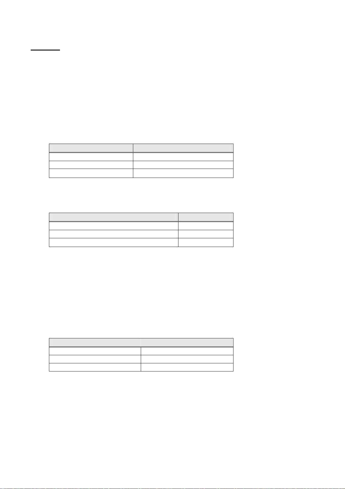
BHT-700Q
The readable barcodes include, among 2D codes, QR code, PDF417, MaxiCode, Data Matrix, and
EAN·UCC composite, and, among barcodes, universal product code, interleaved 2of5 (ITF), Codabar
(NW-7), Code 39, Code 93, Code 128, and RSS. Further, the BHT-700Q can read EAN-128 with Code
128 (read specified). (For details of readable codes, refer to the Instruction Manual.)
□ QR Codes (Q)
Syntax
Q [: [symbol type[min. code version [−max. code version]]][split code scanning mode]
[;symbol type[min code version[-max code version]]]
[;symbol type[min code version[-max code version]]]]
For symbol type, the following values are available:
Symbol type Readable code
S Micro QR
M QR model 1
L QR model 2
If you omit the symbol type, you can read Micro QR, QR model 1, and QR model 2.
The minimum and maximum code versions refer to those of QR code that can be read. The table
below shows the possible ranges by symbol type.
Allowable range of code version Symbol type
1 − 4
1 − 22
1 − 40
The minimum and maximum code versions must satisfy the following relationship:
Minimum code version ≤ Maximum code version
If you omit both the minimum and maximum code versions, you can read QR codes of a full range (up
to the maximum allowable) of code versions for each symbol type. If you omit only the maximum code
version, you can read only the QR code of the minimum code version you specify.
In split code scanning mode, you can read QR code symbols that are split into a maximum of 16
segments (sub-codes). You can specify any of the edit mode, batch edit mode, and non-edit mode as
shown below.
Split code scanning mode
E Enable in edit mode
B Enable in batch edit mode
C Enable in non-edit mode
If you specify "E," "B," and "C," the latest specification takes effect.
If you do not specify the split code scanning mode, the BHT cannot read split QR code symbols.
[Ex] To enable the BHT to read split codes:
BHT_EnableBar (TEXT ("FB"), TEXT ("Q:M5-14E;L1-40;S1-4") )
S
M
L
71
Page 77

In scannning a split code in edit mode, the maximum data length is 8,192 bytes. Data exceeding 8,192
bytes causes a read error to be recognized and the beeper to sound for 500 ms. The read data will be
destroyed.
When a split code is read in non-edit mode, the read data is stored into the barcode buffer in the
following format:
The sub-code number, number of sub-codes, and parity are converted into hexadecimal characters.
The sub-code number is expressed in hexadecimal notation; for example, 0 (30h) for the first, and F
(46h) for the 16
example, 1 (31h) for the splitting into 2 segments, and F (46h) for the splitting into 16 segments.
The parity is provided for sum checking of the read data. It also serves as the delimiter between a
group of split codes from another group.
In split code scanning, the beeper sounds as follows: Upon reading the first split code of a QR code, it
beeps twice, signaling the start of the split code scanning mode. Thereafter, the beeper sounds once
each time a split code is read, except the last one, which causes the beeper to sound three times,
signaling the end of the split code scanning mode.
All split codes belonging to a QR code must be read, no matter what sequence it may be. Once read, a
split code cannot be read again until all the other split codes belonging to the other QR code have
been read.
In any of the following events, the split code scanning will be terminated, even if the scanning of all split
codes of the QR code is not complete. If scanning is terminated in this manner in edit mode, all the
data that has been read up to that point will be destroyed.
・ A non-splti code has been read:
In this case, the data that has been read will be stored into the barcode buffer.
・ A split code belonging to another QR code has been read:
The BHT initiates the reading of the new sequence of split code scanning.
・ The barcode reading window has been put away from the barcode for more than 3 seconds in the
・ The illuminating LED has been turned OFF by a trigger switch, i.e., in the momentary switch mode
□ PDF417(Y)
Syntax
Y [;[symbol type]]
For symbol type, you can specify one of the values shown below.
If you do not specify the symbol type, both MicroPDF417 and PDF417 can be read.
Sub-code no
No. of sub-codes Parity Read data
Sub-code no., No. of sub-codes: 1 byte (hex.) (0 − F)
Parity: 2 bytes (hex.) (00 − FF)
th
. Likewise, the number of sub-codes is expressed in hexadecimal notation; for
momemntary switch mode, alternate switch mode, or continuous read mode; or more than 5
seconds has elapsed since a split code was read.
or auto-off mode, the trigger switch has been released, or in the alternate switch mode, the trigger
switch has been pressed again.
Symbol type Applicable code
S MicroPDF417
M PDF417
72
Page 78
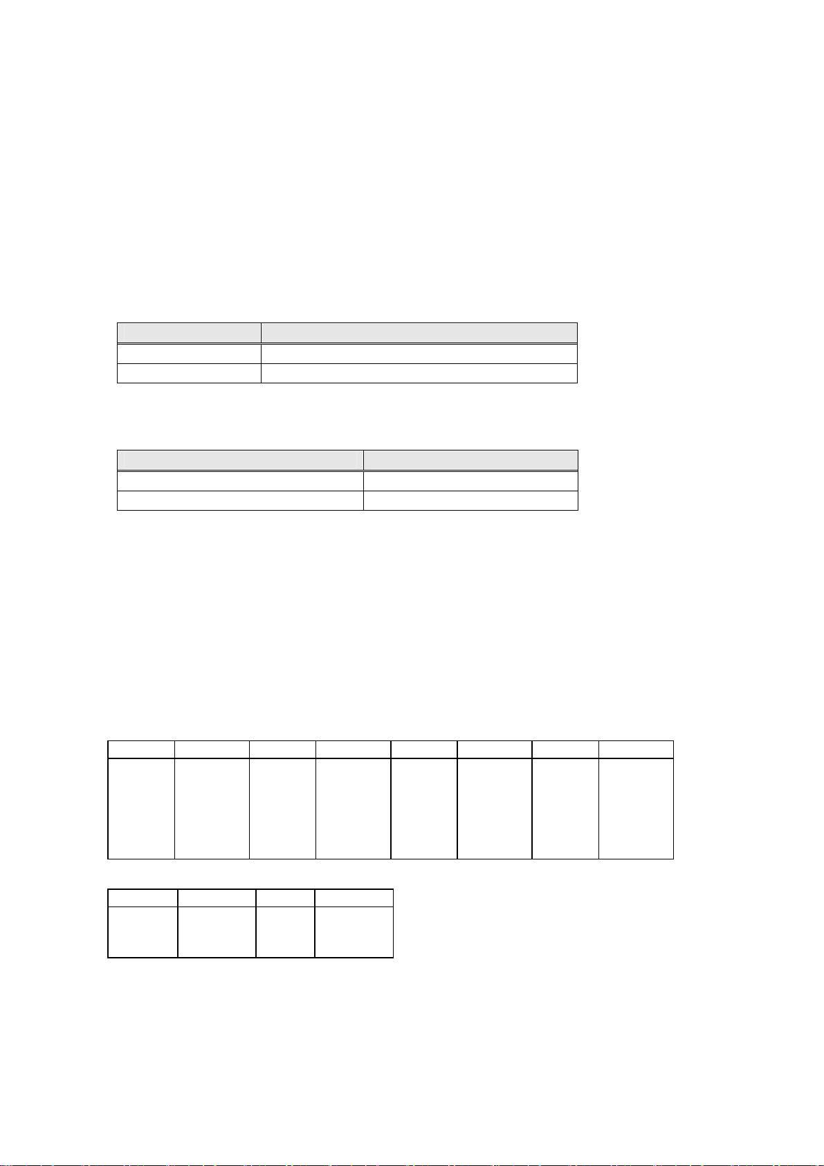
□ MaxiCode(X)
Syntax
X
□ MaxiCode(Z)
Syntax
Z [:[symbol type [min code no.[−max code no.]]]
[;symbol type [min code no.[−max code no.]]]]
For symbol type, you can specify one of the values shown below.
“min code no.” and “max code no.” are the minimum and maximum DataMatrix code numbers that
can be read, respectively. The table below shows the allowable range of code numbers by symbol
type.
If you do not specify the symbol type, both Square Data Matrix and Rectangular Data Matrix can be
read.
“min code no.” and “max code no.” must satisfy the following relationship:
If you omit both the minimum and maximum code numbers, you can read DataMatrix codes of a full
range (up to the maximum allowable) of code numbers for each symbol type. If you omit only the
maximum code number, you can read only the DataMatrix code of the minimum code number you
specify. The table below shows the correspondence between the code number and the number of cells.
Symbol type Applicable code
S Square Data Matrix
R Rectangular Data Matrix
Allowable range of code number Symbol type
1 to 24 S
1 to 6 R
min code no. ≤ max code no.
S (Square Data Matrix)
Code No
1
2
3
4
5
6
ROWxCOL
10x10
12x12
14x14
16x16
18x18
20x20
R (Rectangular Data Matrix)
Code No
ROWxCOL
1
2
3
□ EAN·UCC Composite(V)
Syntax
V
8x18
8x32
12x26
Code No
7
8
9
10
11
12
Code No
4
5
6
ROWxCOL
22x22
24x24
26x26
32x32
36x36
40x40
ROWxCOL
12x36
16x36
16x48
Code No
13
14
15
16
17
18
73
ROWxCOL
44x44
48x48
52x52
64x64
72x72
80x80
Code No
19
20
21
22
23
24
ROWxCOL
88x88
96x96
104x104
120x120
132x132
144x144
Page 79

□ Universal product code (A)
Syntax
st
A [:[code][1
character [2nd character]] [supplemental]]
Specify one of the codes listed below.
Code Barcode type
A EAN-13 (JAN-13), UPC-A
B EAN-8 (JAN-8)
C UPC-E
If you do not specify any of the codes, all of the above-listed codes can be read.
The first and second characters are the first characters representing the country flag and must be a
numeral (0 through 9) each. A question mark (?) serves as a wild card.
“supplemental” refers to the reading of an add-on code. Specifying “S” as “supplemental” enables the
BHT to read add-on codes.
To specify multi-line code reading, first specify “&” and then specify this syntax as many times as the
number of rows to be read. The code cannot be omitted.
For multi-line code reading, refer to the section on multi-line code reading.
[Ex] Reading 3 rows of a universal product code:
BHT_EnableBar (TEXT ("FB"), TEXT ("&,A:A,A:B,A:C"))
74
Page 80

□ Interleaved 2of5 (ITF) (I)
Syntax
I [:[min no. digits [−max no. digits]][CD][;[1
“min no. digits” and “max no. digits” are the minimum and maximum numbers of digits of the barcode.
You can specify any pair of numbers between 2 and 99 (inclusive) that satisfy the following
relationship:
min no. digits ≤ max no. digits
If you omit both the minimum and maximum numbers of digits, the BHT can read barcodes whose
lengths are between the minimum number of digits specified in system mode and 99 (inclusive). If you
omit only the maximum number of digits, the BHT can read only barcodes of the length specified by
“min no. digits.”
“CD” represents the check digit. If you specify “C,” the barcode will be checked according to MOD-10.
The check digit(s) is (are) included in the number of digits.
To specify multi-line code reading, first specify “&” and then specify this syntax as many times as the
number of rows to be read. In this syntax, “;” and the portion after it are valid only in the case of multiline code reading. Specify a numeral (0 − 9) in the first and second characters. For multi-line code
reading, refer to the section on multi-line code reading.
[Ex] Reading two rows of an ITF code:
BHT_EnableBar (TEXT ("FB"), TEXT ("&,I:;12,I:;23"))
st
character [2nd character]]]]
75
Page 81

□ Codabar (NW-7) (N)
Syntax
N [:[min no. digits [− max no. digits]][startstop] [CD]]
“min no. digits” and “max no. digits” are the minimum and maximum numbers of digits of the barcode.
You can specify any pair of numbers between 3 and 99 (inclusive) that satisfy the following
relationship:
min no. digits ≤ max no. digits
If you omit both the minimum and maximum numbers of digits, the BHT can read barcodes whose
lengths are between the minimum number of digits specified in system mode and 99 (inclusive). If you
omit only the maximum number of digits, the BHT can read only barcodes of the length specified by
“min no. digits.”
“startstop” means the start character and the stop character. Specify A, B, C, or D. A question mark
(?) serves as a wild card. The start and stop characters are included in the number of digits. “A”
through “D” are stored in the barcode buffer as “a” through “d.”
“CD” represents the check digit. If you specify “C,” the barcode will be checked according to MOD-16.
The check digit(s) is (are) included in the number of digits.
To specify multi-line code reading, first specify “&” and then specify this syntax as many times as the
number of rows to be read. For multi-line code reading, refer to the section on multi-line code reading.
[Ex] Reading 3 rows of a Codabar:
BHT_EnableBar (TEXT ("FB"), TEXT ("&,N:8,N:6,N:4"))
76
Page 82

□ Code 39 (M)
Syntax
M [:[min no. digits [−max no. digits]][CD][;[1
“min no. digits” and “max no. digits” are the minimum and maximum numbers of digits of the barcode.
The start character and the stop character are not included in the number of digits here. You can
specify any pair of numbers between 1 and 99 (inclusive) that satisfy the following relationship:
If you omit both the minimum and maximum numbers of digits, the BHT can read barcodes whose
lengths are between 1 and 99 (inclusive). If you omit only the maximum number of digits, the BHT can
read only barcodes of the length specified by “min no. digits.”
“CD” represents the check digit. If you specify “C,” the barcode will be checked according to MOD-43.
The check digit(s) is (are) included in the number of digits.
To specify multi-line code reading, first specify “&” and then specify this syntax as many times as the
number of rows to be read. In this syntax, “;” and the portion after it are valid only in the case of multiline code reading. Specify a numeral (0 − 9) in the first and second characters. For multi-line code
reading, refer to the section on multi-line code reading.
[Ex] Reading 2 rows of a Code 39:
BHT_EnableBar (TEXT ("FB"), TEXT ("&,M:;12,M:;23"))
min no. digits ≤ max no. digits
st
character [2nd character]]]]
77
Page 83

□ CODE-93 (L)
Syntax
L [: [min.no.digits [-max.no.digits]][;1
Where
min.no.digits and max.no.digits are the minimum and maximum numbers of digits for barcodes to
be read by the BHT, respectively. These should be numerals from 1 to 99, excluding start/stop
characters and check digits, and should satisfy the following condition:
min no. digits ≤ max no. digits
If both the min.no.digits and max.no.digits are omitted, then the default reading range is 1 to 99
digits. If only the max.no.digits is omitted, the BHT can only read the number of digits specified by
min.no.digits.
[Ex.]To enable the BHT to scan Code 93 with min.no.digits 6 and max.no.digits 12:
BHT_EnableBar (TEXT ("FL"), TEXT ("L:6-12" ))
[Ex.]To enable the BHT to scan Code 93 with min.no.digits 6 and max.no.digits 10, or min.no.digits
20 and max.no.digits 40:
BHT_EnableBar (TEXT ("FL"), TEXT ("L:6-10, L:20-40" ))
NOTE: Neither start/stop characters nor check digits will be transferred to the barcode buffer.
To specify multi-line code reading, specify “&” followed by the above syntax as many times as the
number of rows to be read. In the above syntax, information following “;” is valid only for multi-line
code reading. Specify 0 to 9 for the 1
reading for further details of specifying multi-line code reading.)
[Ex.] To read 2 rows of Code 93:
BHT_EnableBar (TEXT ("FB"), TEXT ("&, L:;12, L:;23"))
st
digit [-2nd digit]]]]
st
and 2nd digits. (Refer to the section on multi-line code
78
Page 84

□ Code 128 (K)
Syntax
K [:[min no. digits [−max no. digits]][;[1
“min no. digits” and “max no. digits” are the minimum and maximum numbers of digits of the barcode.
The start character and the stop character are not included in the number of digits here. You can
specify any pair of numbers between 1 and 99 (inclusive) that satisfy the following relationship:
min no. digits ≤ max no. digits
If you omit both the minimum and maximum numbers of digits, the BHT can read barcodes whose
lengths are between 1 and 99 (inclusive). If you omit only the maximum number of digits, the BHT can
read only barcodes of the length specified by “min no. digits.”
The start character, the stop character, and the check digit are not stored into the barcode buffer.
To specify multi-line code reading, first specify “&” and then specify this syntax as many times as the
number of rows to be read. In this syntax, “;” and the portion after it are valid only in the case of multiline code reading. Specify a numeral (0 − 9) in the first and second characters. For multi-line code
reading, refer to the section on multi-line code reading.
[Ex] Reading 2 rows of a Code 128:
BHT_EnableBar (TEXT ("FB"), TEXT ("&,K:;12,K:;23"))
st
character [2nd character]]]]
79
Page 85

Positions of special characters
When a code consisting only of special characters (FNC, CODEA, CODEB, CODEC, and SHIFT
characters) or a code containing FNC3 has been read, the read data is not stored into the barcode
buffer. When beeper sounding is enabled, the beeper sounds.
Handling of FNC characters
(1) FNC1
The FNC1 character located 1 or 2 places after the start character will not be stored into the barcode
buffer. An FNC1 character located elsewhere will be converted into a GS character (1Dh) and stored
into the barcode buffer.
A code in which an FNC character immediately follows the start character is EAN-128, in which case
the code mark is “W” instead of “K.”
(2) FNC2
For a barcode containing an FNC2 character, the data will not be temporarily stored. Instead, the data
code excluding the FNC2 character will be stored into the barcode buffer.
(3) FNC3
If a barcode contains an FNC3 character, the read data will be regarded as invalid and will not be
stored into the barcode buffer. When the indicator LED and the vibrator are enabled by the
BHT_EnableBar function, the indicator LED and the vibrator will b e tur ne d ON.
(4) FNC4
The FNC4 character converts data encoded by code set A or B into the extended ASCII format (normal
ASCII + 128). One FNC4 character converts one data character immediately following it into the
extended ASCII format.
A pair of contiguous FNC4 characters converts into the extended ASCII format all the data characters
following it before another pair of contiguous FNC4 characters or a stop character. An exception is
when a stand-alone FNC4 character exists in this string of characters, in which case one data
character immediately following it will not be converted.
Also, the GS character created from an FNC1 character will not be converted into the extended ASCII
format.
80
Page 86

■ Multi-line code reading
To specify Multi-line code reading, specify “&” followed by the codes to be read. Up to three rows can
be specified.
Syntax
“&, (code in 1
st
row), (code in 2nd row)[, (code in 3rd row)]”
The codes supported in multi-line code reading are the universal product code, interleaved 2of5 (ITF),
Codabar (NW-7), Code 39, and Code 128 (all among barcodes).
(1) Multi-line code reading is independent of single-row code reading.
[Ex] Reading universal product code EAN-8 and EAN-13 (2 rows):
BHT_EnableBar (TEXT ("FB"), TEXT ("&,A:B,A:A"))
[Ex] Reading 1 row of universal product code EAN-8 and 2 rows of Code 39:
BHT_EnableBar (TEXT ("FB"), TEXT ("A:B,&,M,M"))
(2) You can specifiy a 2D code and a multi-line code simultaneously.
[Ex] Reading a QR code and 3 rows of code 39:
BHT_EnableBar (TEXT ("FB"), TEXT ("Q,&,M,M,M"))
(3) In Multi-line code reading, you can specify the reading sequence using the first two characters
(start/stop in the case of Codabar).
[Ex] Reading 3 rows of ITF (with character specification) in the following sequence: code beginning
with “12,” code with CD beginning with “21” of 6 – 10 digits in length, and code beginning with “23” of
12 digits in length
BHT_EnableBar (TEXT ("FB"), TEXT ("&,I:;12,I:6-10C;21,I:12;23"))
You can also specify a single character.
[Ex] Reading a universal product code EAN and ITF (with character specification) in the following
sequence: EAN beginning with”49” and ITF beginning with”2” of 6 – 10 digits in length.
BHT_EnableBar (TEXT ("FB"), TEXT ("&,A:A49,I:6-10;2"))
(4) Data will be output in the specified sequence.
[Ex] Data is to be output in the sequence of EAN-8 beginning with “12” - EAN-8 beginning with “21.”
BHT_EnableBar (TEXT ("FB"), TEXT ("&,A:B12,A:B21"))
Note, however, that if you specify the same character and the same number of digits, then the output
sequence is unpredictable.
[Ex] Reading 2 rows of ITF, both beginning with “49” and having a length of 6 digits:
BHT_EnableBar (TEXT ("FB"), TEXT ("&,I:6;49,I:6;49"))
In this example, it is unpredictable, for example, which will be output first, ITF”495678” or ITF “498765.”
81
Page 87

(5) If the same code (with the same code type and the same data code) appears more than once in a
multi-line code, the BHT cannot read it.
[Ex] A code consisting of EAN-13: “4912345678904” in the first row, EAN-13; “1200000000003” in the
second row, and EAN-13 “4912345678904” in the third row cannot be read with the following
instruction:
BHT_EnableBar (TEXT ("FB"), TEXT ("&,A:A49,A:A12,A:A49"))
(6) If you specify the same code type, the same number of digits, and the same conditions for single-row
reading and multi-line code reading, the BHT cannot read the single-row code.
[Ex] If you have a single-row EAN-13 code “'4901234567894'” and a two-row EAN-13 code consisting
of “'4909876543214'” in the first row and “1200000000003” in the second row, you cannot read them
using the following instruction:
BHT_EnableBar (TEXT ("FB"), TEXT ("A:A49,&,A:A49,A:A12"))
(7) In multi-line code reading, an ITF code less than 4 digits in length cannot be read unless you specify
the number of digits.
(8) You cannot specify multiple-row code reading for add-on codes in the universal product code.
(9) You cannot specify multiple-row code reading for the RSS code.
(10) When you have selected the point scan mode, you cannot specify multiple-row code reading.[
□ RSS (R)
Syntax
R
82
Page 88

BHT_DisableBar
Description:
Close the barcode device file to disable barcode reading.
Syntax:
DWORD BHT_DisableBar (void)
Parameters
None
Return value
Error code Meaning
ERROR_SUCCESS Successful completion
ERROR_INVALID_HANDLE Barcode device file not opened
83
Page 89
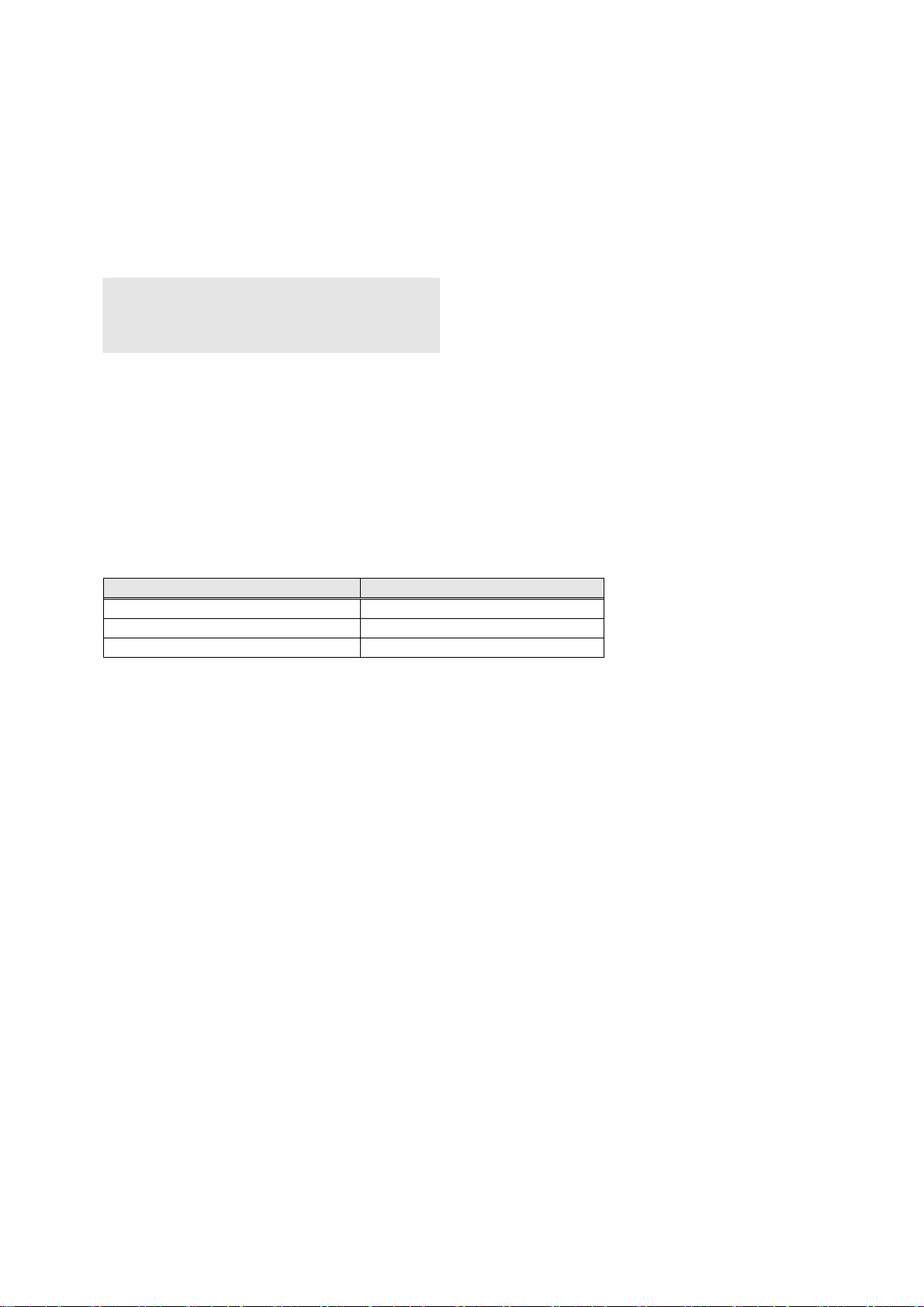
BHT_ReadBar
Description
Read out data read from the barcode buffer.
If the string length longer than that of the read barcode is specified to dwBarLen, the remaining area
following the read barcode will be filled with NULL codes.
If barcode reading is not enabled, an error (ERROR_INVALID_HANDLE) will result.
Syntax:
DWORD BHT_ReadBar (
TCHAR* pwchBuffer ,
DWORD dwBarLen ,
DWORD* pdwActualBarLen )
Parameters
pwchBuffer
[out] Heading address of the storage buffer storing the read data
dwBarLen
[in] Maximum length of data to be read
pdwActualBarLen
[out] Length of data read
Return value
Error code Meaning
ERROR_SUCCESS Successful completion
ERROR_INVALID_HANDLE Barcode device file not opened.
ERROR_INVALID_PARAMETER No storage address specified.
84
Page 90

BHT_ReadBarEx
Description
Read out data from the barcode buffer and encodes it into the specified data format.
If the length of the read data is shorter than the specified maximum data length (dwBarLen), the excess
part will be filled with 0s.
If barcode reading is disabled, an error (ERROR_INVALID_HANDLE) will be caused.
Syntax:
DWORD BHT_ReadBarEx (
DWORD dwDataType,
LPVOID lpBuffer,
DWORD dwBarLen,
DWORD* pdwActualBarLen )
Parameters
dwDataType
[in] Encoding format
READ_CODE_BINARY : binary data (no encoding)
READ_CODE_UNICODE : unicode data
lpBuffer
[in] Starting address of the read data in the storage buffer
dwBarLen
[in] Maximum read data length (maximum length of data to be read out)
pdwActualBarLen
[out] Length of data read
Return value
Error code Meaning
ERROR_SUCCESS Successful completion
ERROR_INVALID_HANDLE Barcode device file not opened.
ERROR_INVALID_PARAMETER
The specified encoding is wrong.
No storage address specified.
85
Page 91

BHT_GetBarType
Description
BHT-700B
Read the barcode type and the number of digits of a barcode read most recently.
If no barcode has been read after the BHT was turned on, the function gets "0."
BHT-700Q
Read the barcode type and the number of digits of a barcode read most recently.
If no barcode has been read after the BHT was turned on, the function gets "0."
When a multiple-row code has been read, this fact is communicated to the caller and the total number of
digits in the multiple-row code is returned.
To get the information for a specific row, call BHT_GetBarInfo.
When an EAN·UCC composite code has been read, this fact is communicated to the caller and the total
number of digits in the EAN·UCC composite code is returned. To get the information for a specific row,
call BHT_GetBarInfo.
Syntax
DWORD BHT_GetBarType (
DWORD* pdwBarMark ,
DWORD* pdwBarlen )
Parameters
pdwBarMark
[out] Address for storing the barcode type
pdwBarlen
[out] Address for storing the barcode length
The pdwBarMark contains one of the following letters representing code types:
Barcode type pdwBarMark
(No code read) 0
EAN-13 (JAN-13), UPC-A 'A'
EAN-8 (JAN-8) 'B'
UPC-E 'C'
ITF 'I'
STF (Only for BHT-700B) 'H'
CODABAR (NW-7) 'N'
CODE-39 'M'
CODE-93 'L'
CODE-128 'K'
EAN-128 'W'
MSI (Only for BHT-700B) 'P'
RSS 'R'
QR code (Only for BHT-700Q) 'Q'
Split QR code (in non-edit mode)
(Only for BHT-700Q)
PDF417 (Only for BHT-700Q) 'Y'
Maxi Code (Only for BHT-700Q) 'X'
Data Matrix (Only for BHT-700Q) 'Z'
Multi-line code (Only for BHT-700Q) '&'
Composite (Only for BHT-700Q) 'V'
Return value
Error code Meaning
ERROR_SUCCESS Successful completion
ERROR_INVALID_PARAMETER Storage address not specified.
'S'
86
Page 92

BHT_ GetBarInfo
Description
BHT-700B
Read the information on the code read most recently, including the code type and the number of digits in
the code.
If no barcode has been read after the BHT was turned on, the function gets "0" for both the code type
and the number of digits.
BHT-700Q
Read the information on the code read most recently, including the code type and the number of digits in
the code.
If no barcode has been read after the BHT was turned on, the function gets "0" for both the code type
and the number of digits.
When a multi-line code has been read, the information on all the rows is obtained in an array format. Also,
the number of rows in the code is obtained.
When an RSS·EAN Composite code has been read, the information on all the codes constituting the
composite code is obtained in an array format. Also, the number of codes in the composite code is
obtained.
Syntax
DWORD BHT_GetBarInfo (
ST_CODE_INFO* pstInfo ,
DWORD* pdwCodeNum )
Parameters
pstInfo
[out] Destination address into which the code information is to be stored
pdwCodeNum
[in] No. of codes to be obtained
[out] Destination address into which the number of codes is to be stored. This is set to “1” when a code
other than a multiple-row code or an EAN·UCC composite code has been read.
Shown below is the format of the structure containing code information. For the relationship between
dwType and code type, refer to BHT_GetBarType.
struct ST_CODE_INFO {
DWORD dwType; // code type
DWORD dwLen; // no. of digits
) ;
Return value
Error code Meaning
ERROR_SUCCESS Successful completion
ERROR_INVALID_PARAMETER Storage address not specified.
If you specify NULL in pstCodeInfo, the number of elements of ST_CODE_INFO necessary to store the
read code will be stored into pdwCodeNum.
An error occurs if a value greater than MAX_NUM_CODE_1D_SCANNER (when using the BHT-700B) or
MAX_NUM_CODE_2D_SCANNER (when using the BHT-700Q) is specified for pdwCodeNum.
87
Page 93
BHT_GetBarNum
Description
Read the number of digits of the barcode remaining in the barcode buffer.
If barcode reading is not enabled, an error (ERROR_INVALID_HANDLE) will result.
Syntax
DWORD BHT_GetBarNum (
DWORD* pdwCodeNum )
Parameters
pdwCodeNum
[out] Address for storing the barcode length
Return value
Error code Meaning
ERROR_SUCCESS Successful completion
ERROR_INVALID_HANDLE Barcode device file not opened
ERROR_INVALID_PARAMETER Storage address not specified
88
Page 94
BHT_GetBarChkDgt
Description
Calculate a check digit (CD) of
dwCDType.
Syntax
DWORD BHT_GetBarChkDgt (
TCHAR* pwchBarbuf ,
DWORD dwCDType ,
DWORD* pdwChkdgt )
Parameters
pwchBarbuf
[in] Heading address of barcode data storage buffer
dwCDType
[in] Check digit type
Barcode type and the corresponding calculation method
Barcode Type dwCDType Calculation Method
EAN(JAN), UPC 'A' MOD10 (Modulo arithmetic-10)
ITF 'I' MOD10 (Modulo arithmetic-10)
STF (only for BHT-700B) 'H' MOD10 (Modulo arithmetic-10)
CODABAR (NW-7) 'N' MOD16 (Modulo arithmetic-16)
CODE-39 'M' MOD43 (Modulo arithmetic-43)
MSI (only for BHT-700B) 'P' MOD10 (Modulo arithmetic-10)
pdwChkdgt
(out) Address for storing the check digit calculated
Return value
Error code Meaning
ERROR_SUCCESS Successful completion
ERROR_INVALID_PARAMETER
the barcode data according to the calculation method specified by
Invalid check digit type.
Invalid barcode data.
Storage address not specified.
89
Page 95

Comment:
barcode data contains a character(s) out of the specification of the barcode type specified by
If
dwCDType, then this function sets "0" and returns an error code. However, if only the CD position
character in
as one-character string.
[Ex 1] BHT_GetBarChkDgt(TEXT("494AB4458"), 'A', &dwChkDgt);
[Ex 2] BHT_GetBarChkDgt(TEXT("4940045X"), 'A', &dwChkDgt);
[Ex 3] BHT_GetBarChkDgt(TEXT("a0ef3-a"), 'N', &dwChkDgt);
[Ex 4] BHT_GetBarChkDgt(TEXT("a123Qa"), 'N', &dwChkDgt)
barcode data is out of the specification, this function calculates the correct CD and returns it
"A" and "B" are out of the specification of EAN or UPC, so dwChkDgt is "0" and the function
returns an error code.
"X" is out of the specification but it is a CD position character, so this function calculates the
correct CD and dwChkDgt is "8."
"e" and "f" are out of the specification of Codabar (NW-7), so dwChkDgt is "0" and the
function returns an error code.
"Q" is out of the specification but it is a CD position character, so this function calculates the
correct CD and dwChkDgt is "-."
90
Page 96

When dwCDType is A (EAN or UPC), this function identifies the EAN or UPC depending upon the data
length (number of digits) as listed below. If the data length is a value other than 13, 8, and 7, this
function gets "0" and returns an error code.
Data length of barcode data Barcode type
13 EAN-13 (JAN-13), UPC-A
8 EAN-8 (JAN-8)
7 UPC-E
To check whether the CD is correct: Pass a CD-suffixed barcode data to the BHT_GetBarChkDgt
function as shown below. If the returned value is equal to the CD, the CD data is suitable for the
barcode data.
[Ex]
BHT_GetBarChkDgt(TEXT("49400458"), 'A', &dwChkDgt);
if ( dwChkDgt == '8' ) {
printf("CD OK");
}
To add a CD to barcode data: Pass barcode data followed by a dummy character to the
BHT_GetBarChkDgt function as shown below. The returned value will become the CD to be replaced
with the dummy character.
[Ex]
wcscpy(wchBarData, TEXT("4940045"));
wcscpy(wchBarData1, wchBarData);
wcscat(wchBarData1, TEXT("0"));
BHT_GetBarChkDgt(wchBarData1, 'A', &dwChkDgt);
wprintf(TEXT("CD = %s%c"), wchBarData, dwChkDgt);
Result
> CD = 49400458
91
Page 97

When
If not,
To check whether the CD is correct: Pass a CD-suffixed barcode data to the BHT_GetBarChkDgt
function as shown below. If the returned value is equal to the CD, the CD data is suitable for the
barcode data.
[Ex]
BHT_GetBarChkDgt(TEXT("123457"), 'I', &dwChkDgt);
if ( dwChkDgt == '7' ) {
}
To add a CD to barcode data: Pass barcode data followed by a dummy character to the
BHT_GetBarChkDgt function as shown below. The returned value will become the CD to be replaced
with the dummy character.
[Ex]
wcscpy(wchBarData, TEXT("12345"));
wcscpy(wchBarData1, wchBarData);
dwCDType is I (ITF), the length of barcode data must be an even number of two or more digits.
this function gets "0" and returns an error code.
printf("CD OK");
wcscat(wchBarData1, TEXT("0"));
BHT_GetBarChkDgt(wchBarData1, 'I', &dwChkDgt);
wprintf(TEXT("%s%c"), wchBarData, dwChkDgt);
Result
> CD = 123457
92
Page 98

When
gets "0" and returns an error code.
To check whether the CD is correct: Pass a CD-suffixed barcode data to the BHT_GetBarChkDgt
function as shown below. If the returned value is equal to the CD, the CD data is suitable for the
barcode data.
[Ex]
BHT_GetBarChkDgt(TEXT("12345678905"), 'H', &dwChkDgt);
if ( dwChkDgt == '5' ) {
}
To add a CD to barcode data: Pass barcode data followed by a dummy character to the
BHT_GetBarChkDgt function as shown below. The returned value will become the CD to be replaced
with the dummy character.
[Ex]
wcscpy(wchBarData, TEXT("1234567890"));
wcscpy(wchBarData1, wchBarData);
dwCDType is H (STF), the length of barcode data must be two or more digits. If not, this function
printf("CD OK");
wcscat(wchBarData1, TEXT("5"));
BHT_GetBarChkDgt(wchBarData1, 'H', &dwChkDgt);
wprintf(TEXT("%s%c"), wchBarData, dwChkDgt);
Result
> CD = 12345678905
93
Page 99

When
start and stop characters. If not,
To check whether the CD is correct: Pass a CD-suffixed barcode data to the BHT_GetBarChkDgt
function as shown below. If the returned value is equal to the CD, the CD data is suitable for the
barcode data.
[Ex]
}
To add a CD to barcode data: Pass barcode data followed by a dummy character to the
BHT_GetBarChkDgt function as shown below. The returned value will become the CD to be replaced
with the dummy character.
[Ex]
dwCDType is N (Codabar), the length of barcode data must be three digits or more including
this function gets "0" and returns an error code.
BHT_GetBarChkDgt(TEXT("a0123-a"), 'M', &dwChkDgt);
if ( dwChkDgt == '-' ) {
printf("CD OK");
wcscpy(wchBarData, TEXT("a0123a"));
len = wcslen(wchBarData);
wcsncpy(wchTmp1BarData, wchBarData, len – 1);
wcscpy(wchTmp2BarData, wchTmp1BarData);
wcscat(wchTmp2BarData, TEXT("0"));
wcscat(wchTmp2BarData, &(wchBarData[len – 1]));
BHT_GetBarChkDgt(wchTmp2BarData) 'M', &dwChkDgt);
wprintf(TEXT("%s%c%s"), wchTmp1BarData, dwChkDgt, &wchTmp2BarData[len-1]));
Result
> CD = a0123-a
94
Page 100

When
start and stop characters. If not,
To check whether the CD is correct: Pass a CD-suffixed barcode data to the BHT_GetBarChkDgt
function as shown below. If the returned value is equal to the CD, the CD data is suitable for the
barcode data.
[Ex]
dwCDType is M (Code 39), the length of barcode data must be two or more digits except for
this function gets "0" and returns an error code.
BHT_GetBarChkDgt(TEXT("CODE39W"), 'M', &dwChkDgt);
if ( dwChkDgt == 'W' ) {
printf("CD OK");
}
To add a CD to barcode data: Pass barcode data followed by a dummy character to the
BHT_GetBarChkDgt function as shown below. The returned value will become the CD to be replaced
with the dummy character.
[Ex]
wcscpy(wchBarData, TEXT("CODE39"));
wcscpy(wchBarData1, wchBarData);
wcscat(wchBarData1, TEXT("0"));
BHT_GetBarChkDgt(wchBarData1, 'M', &dwChkDgt);
wprintf(TEXT("%s%c"), wchBarData, dwChkDgt);
Result
> CD = CODE39W
95
 Loading...