

Page 1
Bar Code Handy Terminal
BHT-400-CE
Class Library Reference Manual
Page 2

Copyright © DENSO WAVE INCORPORATED, 2005
All rights reserved. No part of this publication may be reproduced in any form or by any means without permission in
writing from the publisher.
Specifications are subject to change without prior notice.
All products and company names mentioned in this manual are trademarks or registered trademarks of their
respective holders.
Page 3

Introduction
This reference manual is intended for software developers using VB.NET or C# to develop software applications using
barcode read functions and so forth for the BHT400.
Related Manuals
Please refer to the following related manuals for further information.
• kbifCE User’s Guide
• BHT-400-CE API Reference Manual
• BHT-400B-CE/400BW-CE User’s Manual
Contacts
Please forward any opinions or questions that you may have regarding this manual to the address below or contact us
by telephone.
DENSO WAVE INCORPORATED
MT Bldg. Hall No.2, 4-2-12,Toranomon, Minato-ku, Tokyo, 105-0001 Japan
Tel: +81-3-5472-0477
Latest Information
Please access our Web site using the following URL for the latest information on this manual and our full range of
products.
http://www.denso-wave.com/
More detailed information is available for product owners at our dedicated Web site (QBNet) for registered users.
Please access the above URL for user registration and details on QBNet.
- i -
Page 4

Contents
1. Development Environment ...............................................................................................................1
2. Development Procedure...................................................................................................................2
2.1. Project Creation Procedure......................................................................................................2
2.2. Assignment Procedure .............................................................................................................2
3. Device Control..................................................................................................................................4
4. Barcode Reading..............................................................................................................................5
4.1. Readable Codes.......................................................................................................................5
4.2. Trigger Switch Operation Mode................................................................................................6
4.3. Display LEDs and Beeper Control ...........................................................................................7
4.4. Barcode Data ...........................................................................................................................7
4.5. Check Digit Calculation ............................................................................................................7
5. Wireless Communication..................................................................................................................8
5.1. Wireless Communication System Configuration......................................................................8
5.2. Wireless Communication Parameters......................................................................................9
5.3. Security ..................................................................................................................................10
5.4. Programming..........................................................................................................................11
6. Backlight .........................................................................................................................................12
6.1. Backlight Control ....................................................................................................................13
6.2. Backlight Control Key.............................................................................................................13
6.2. Backlight Control Key.............................................................................................................14
6.3. Backlight Illumination Duration...............................................................................................15
6.4. Brightness ..............................................................................................................................15
6.5. OFF/DIM Toggle.....................................................................................................................15
7. Beeper, Vibrator .............................................................................................................................16
7.1. Beeper/Vibrator Selection ......................................................................................................16
7.2. Beeper, Vibrator Parameters..................................................................................................16
7.3. Beeper Volume.......................................................................................................................17
7.4. Beeper and Vibrator Control ..................................................................................................17
7.5. Priority Order ..........................................................................................................................17
8. Battery Information .........................................................................................................................18
9. Keyboard ........................................................................................................................................19
9.1. Input Mode Change................................................................................................................19
9.2. Function Mode........................................................................................................................19
9.3. Numeric Entry Mode...............................................................................................................20
9.4. Alphabet Entry Mode ..............................................................................................................20
9.5. Magic Key Operation..............................................................................................................21
9.6. Shift Key Operation ................................................................................................................22
9.7. Auto Repeat Function.............................................................................................................23
9.8. Keyboard Type .......................................................................................................................23
10. LED...............................................................................................................................................24
11. Power Management .....................................................................................................................26
- ii -
Page 5

11.1. Standby Transition Conditions..............................................................................................26
11.2. Suspend Transition Conditions.............................................................................................27
12. Updating the OS...........................................................................................................................28
13. Status Display...............................................................................................................................29
14. System Information ......................................................................................................................30
15. Data Communication....................................................................................................................31
15.1. IrDA Interface .......................................................................................................................31
15.2. Connector Interface..............................................................................................................31
15.3. File Transfer .........................................................................................................................31
15.4. ActiveSync Auto Connection ................................................................................................31
16. Namespaces.................................................................................................................................32
17. Class.............................................................................................................................................33
17.1. Scanner ................................................................................................................................35
17.2. Scanner.CodeInfo.................................................................................................................36
17.3. Scanner.Settings ..................................................................................................................37
17.4. BatteryCollection ..................................................................................................................38
17.5. BatteryCollection.Battery......................................................................................................39
17.6. Backlight...............................................................................................................................40
17.7. Backlight.Settings.................................................................................................................41
17.8. LED ......................................................................................................................................42
17.9. LED.UsageCollection ...........................................................................................................43
17.10. Beep ...................................................................................................................................44
17.11. Beep.Settings .....................................................................................................................45
17.12. RF.......................................................................................................................................46
17.13. RF.Profile............................................................................................................................47
17.14. RF.Settings.........................................................................................................................48
17.15. RF.WepKeyCollection.........................................................................................................49
17.16. RF.SiteSurvey.....................................................................................................................50
17.17. RF.Info................................................................................................................................51
17.18. Keys ...................................................................................................................................52
17.19. Keys.Settings .....................................................................................................................53
17.20. SysInfo ...............................................................................................................................54
17.21. SysInfo.Settings .................................................................................................................55
17.22. PwrMng ..............................................................................................................................56
17.23. PwrMng.Settings ................................................................................................................57
17.24. Icon.....................................................................................................................................58
17.25. Icon.Settings.......................................................................................................................59
17.26. Display................................................................................................................................60
17.27. Display.Settings..................................................................................................................61
17.28. SysModification ..................................................................................................................62
17.29. ArgumentException ............................................................................................................63
17.30. ObjectDisposedException ..................................................................................................64
17.31. SecurityException ..............................................................................................................65
17.32. DeviceNotFoundException.................................................................................................66
17.33. DeviceLoadException ........................................................................................................67
- iii -
Page 6

17.34. NotSupportedException .....................................................................................................68
17.35. CommSerial........................................................................................................................69
17.36. FileTransfer ........................................................................................................................70
18. Members.......................................................................................................................................71
18.1. Scanner ................................................................................................................................71
18.2. Scanner.CodeInfo...............................................................................................................113
18.3. Scanner.Settings ................................................................................................................116
18.4. BatteryCollection ............................................................................................................... 129
18.5. BatteryCollection.Battery................................................................................................... 132
18.6. Backlight............................................................................................................................ 142
18.7. Backlight.Settings.............................................................................................................. 146
18.8. LED ................................................................................................................................... 153
18.9. LED.UsageCollection ........................................................................................................ 160
18.10. Beep ................................................................................................................................ 161
18.11. Beep.Settings .................................................................................................................. 169
18.12. RF.................................................................................................................................... 180
18.13. RF.Profile......................................................................................................................... 190
18.14. RF.Settings...................................................................................................................... 210
18.15. RF.WepKeyCollection...................................................................................................... 221
18.16. RF.SiteSurvey.................................................................................................................. 224
18.17. RF.Info............................................................................................................................. 229
18.18. Keys ................................................................................................................................ 234
18.19. Keys.Settings .................................................................................................................. 239
18.20. SysInfo ............................................................................................................................ 255
18.21. SysInfo.Settings .............................................................................................................. 256
18.22. PwrMng ........................................................................................................................... 263
18.23. PwrMng.Settings ............................................................................................................. 267
18.24. Icon.................................................................................................................................. 273
18.25. Icon.Settings.................................................................................................................... 274
18.26. Display............................................................................................................................. 283
18.27. Display.Settings............................................................................................................... 284
18.28. SysModification ............................................................................................................... 285
18.29. CommSerial..................................................................................................................... 292
18.30. FileTransfer ..................................................................................................................... 310
Appendix 1. Key Arrangements....................................................................................................... 334
Appendix 2. Virtual Keyboard and Display Characters ................................................................... 336
- iv -
Page 7

1. Development Environment
Development tool
• Microsoft Visual Studio .NET 2003
Application development kit
• This is a redistributable package intended for use by .NET Compact Framework and Service Pack developers.
- Assembly required for application development
- Tool for application assignment
- CPU: ARMV4I
- SP3 can be downloaded by accessing the following URL:
http://www.microsoft.com/downloads/details.aspx?displaylang=en&FamilyID=7BF313B9-71ED-4E15
-AD6E-315DAE6FAF9F
• DNWA.BHT400CL.dll
- Assembly equipped with dedicated BHT functions such as barcode reading
- Used as a reference when developing applications employing dedicated BHT functions.
- This file can be downloaded from QBNet.
• DNWA.BHT400CL.xml
- DNWA.BHT400CL.dll document comment file
- IntelliSense can be used by storing the file in the same folder as DNWA.BHT400CL.dll.
• DNWA.Tools.BHT.Communication400.dll
- Assembly equipped with file transfer and serial communication functions
- Used as a reference when developing applications employing file transfer and serial communication.
- This file can be downloaded from QBNet.
• DNWA.Tools.BHT.Communication400.xml
- DNWA.Tools.BHT.Communication400.dll document comment file
- IntelliSense can be used by storing the file in the same folder as DNWA.Tools.BHT.Communication400.dll.
• DNWA.Exception.xml
- Assembly equipped with dedicated BHT exceptions
- DNWA.Exception.dll document comment file
- IntelliSense can be used by storing the file in the same folder as DNWA.Exception.dll.
Hardware
• Dedicated BHT-400 USB cable
- Used when employing USB ActiveSync for assignment of applications and debugging.
- 1 -
Page 8

2. Development Procedure
2.1. Project Creation Procedure
1. Store the dedicated BHT class library (dll, xml file) in a suitable folder in the computer used for development.
2. Start up Visual Studio.NET.
3. Select [File] – [New] – [Project…] to create a new project.
4. At the [New Project] dialog box, set the [Project Types:] to “Visual Basic Projects” or “Visual C# Projects”, and
the [Templates] to “Smart Device Application”.
5. At the [Smart Device Application Wizard], set the [What platform do you want to target?] to “Windows CE “, and
the [What project type do you want to create?] to the actual project type to be created.
6. Open the [View] – [Solution Explorer] window.
7. Right-click the [Reference] icon, and select [Add References…] to start up the reference add menu.
8. Press [Browse…] and select the dll saved at step 1.
2.2. Assignment Procedure
Assignment using USB ActiveSync
1. Select [Tools] – [Options…] – [Device Tools] – [Devices] to start up the Device Tool.
2. Press [Save As…] with "Windows CE" selected at the [Show devices for platform:] and enter an appropriate
filename (e.g., “BHT AS”).
3. With the “BHT AS” file created at step 2 selected, set [Transport:] to “TCP Connect Transport”.
4. Press [Configure…] to open the “Configure TCP/IP Transport Settings” dialog box.
5. Select “Obtain an IP address automatically using ActiveSync” for the device IP address.
6. Press [OK] to exit the [Options] menu.
7. Connect the BHT and computer with the USB ActiveSync cable.
8. Select [Build…] – [Build solution] and then assign a solution.
Step 8 only is required from the second time onwards.
Assignment using Smart Device Authentication
1. Connect the BHT to the same network as the computer used for development.
2. Run SDAuthUtilDevice.exe at the BHT and press START.
3. Perform steps 1 to 4 listed above for the “Assignment using USB ActiveSync” procedure.
4. Select “Use Specific IP Address” for the device IP address, and enter the IP address that displays when the
SDAuthUtilDevice.exe file run at step 2 starts up.
5. Press [OK] to exit the [Options] menu.
6. Select [Tools] - [Smart Device Authentication Utility] to start up the Smart Device Authentication Utility.
7. Enter the IP address entered at step 4 in the [Smart Device Authentication Utility] dialog box and press [Set up
device].
8. If authentication is successful, press [Close] at the [Smart Device Authentication Utility] dialog box.
- 2 -
Page 9

9. Select [Build…] – [Build solution] and then assign a solution.
Unless the IP address is changed, step 9 only is required from the second time onwards.
When debugging, change both methods from [Build…] – [Build solution] to [Debug] – [Start].
- 3 -
Page 10
3. Device Control
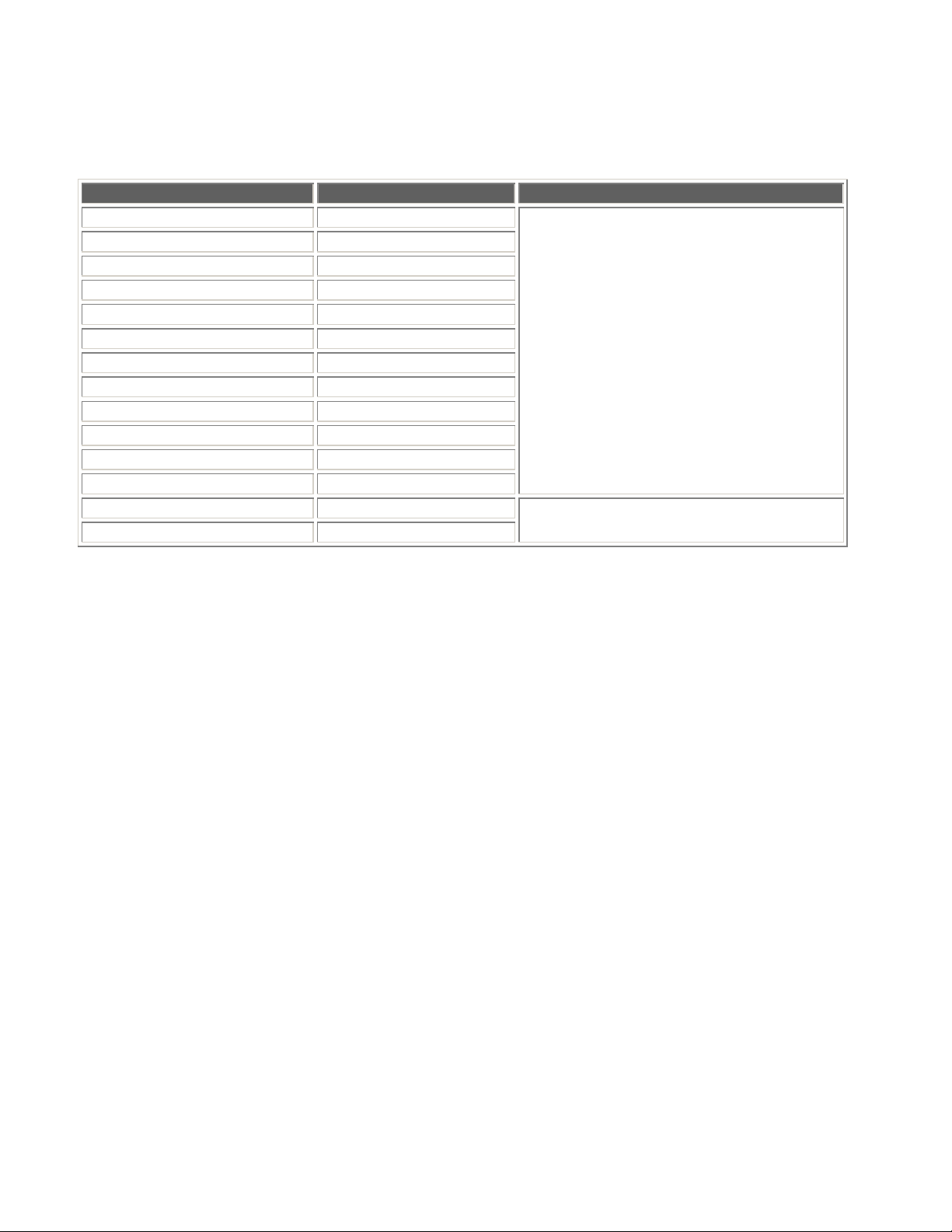
The following table lists devices that can be controlled from the dedicated BHT class library and the respective
classes used.
Function Class Assembly
Barcode reading Scanner
Wireless communication RF
Backlight Backlight
Beeper, vibrator Beep
Battery information Battery
Keyboard Keys
LED LED
Power management PwrMng
OS update SysModification
Status display Icon
Screen control Display
System information SysInfo
Serial communication COM
File transfer FileTransfer
DNWA.BHT400CL.dll
DNWA.Tools.BHT.Communication400.dll
- 4 -
Page 11
4. Barcode Reading
The barcode reading function has the following features.
• Specification of barcode types for which reading is permitted
• Specification of the trigger switch operation mode
• Specification of the method used to notify the operator that reading is complete
• Acquisition of the read barcode data, number of code digits, and code type
• Calculation of check digits
4.1. Readable Codes
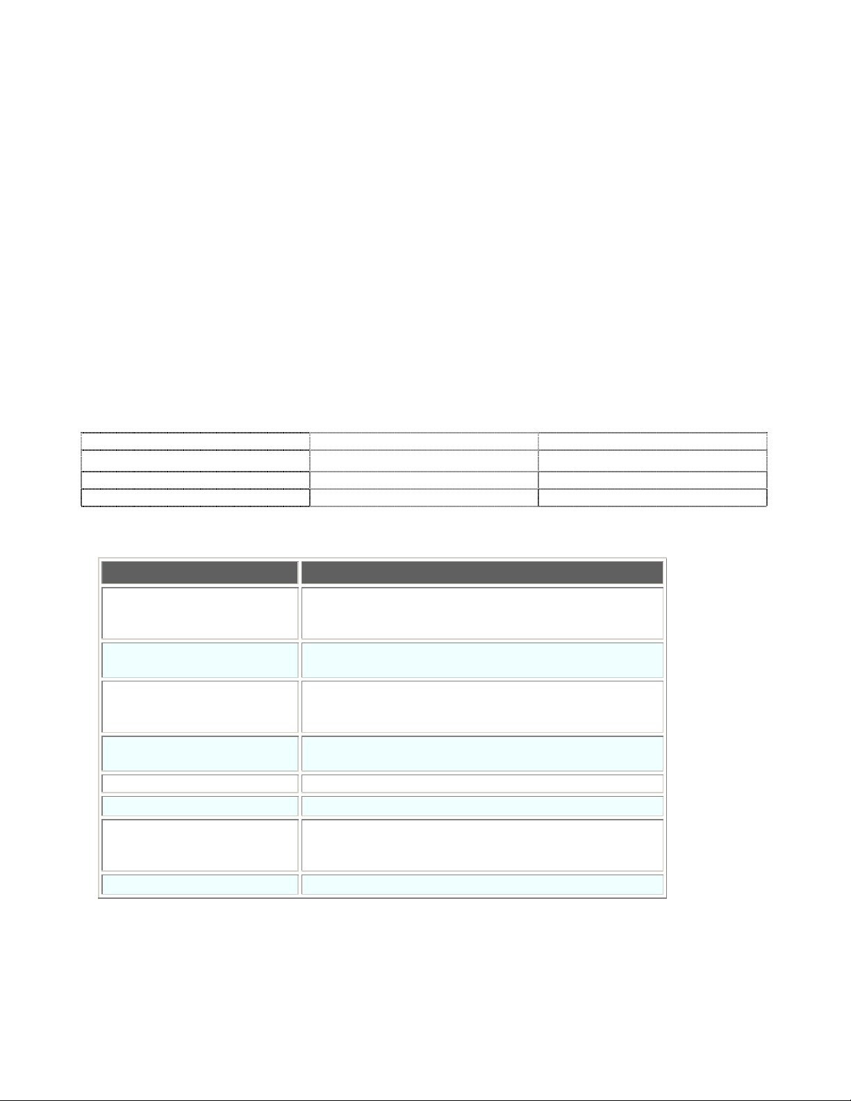
The BHT unit can read the following codes. Codes for which reading is permitted are specified at the
Scanner.RdType property.
EAN-13 (JAN-13) EAN-8 (JAN-8) UPC-A, UPC-E
Interleaved 2of5 (ITF) Standard 2of5 (STF) Codabar (NW-7)
Code-39 Code-93 Code-128 (EAN-128) (*1)
MSI
(*1) Both Code-128 and EAN-128 can be read by specifying Code-128.
The following options can be specified for the above code types.
Code Type Option
EAN-13 (JAN-13)
EAN-8 (JAN-8)
st
character (country flag)
1
Codes with add-on
UPC-A, UPC-E
Interleaved 2of5 (ITF) No. of read digits
Check digits
Codabar
(NW-7)
No. of read digits
Start/stop characters
Check digits
Code-39 No. of read digits
Check digits
Code-93 No. of read digits
Code-128 No. of read digits
Standard 2of5 (STF) No. of read digits
Start/stop characters
Check digits
MSI Single-digit check digits
- 5 -
Page 12

4.2. Trigger Switch Operation Mode
The following four modes exist based on differences in the illumination timing and duration of the illumination LED.
These modes are specified at the Scanner.RdMode property.
Auto-off mode (default)
The illumination LED turns ON when the trigger switch is pressed, and turns OFF again when the trigger
switch is released or a barcode is read. The illumination LED remains ON for a maximum of five seconds
if the trigger switch is held down continuously.
A barcode can be read while the illumination LED is ON. Barcode reading will no longer be possible,
however, after reading of a barcode is complete or a barcode device file is closed.
If the illumination LED turns OFF after five seconds has elapsed since the trigger switch is pressed, the
trigger switch must be pressed again before barcode reading is possible.
Provided the read data is not read out from the barcode buffer, the illumination LED will not turn ON, and
it will not be possible to read the next barcode, even if the trigger switch is pressed.
Momentary switch mode
The illumination LED turns ON and a barcode can be read only when the trigger switch is held down.
Provided the read data is not read out from the barcode buffer, the illumination LED will not turn ON, and
it will not be possible to read the next barcode, even if the trigger switch is pressed.
Alternate switch mode
The illumination LED turns ON when the trigger switch is pressed, and remains ON even after the trigger
switch is released. The illumination LED turns OFF when the barcode device file is closed or when the
trigger switch is pressed again. A barcode can be read while the illumination LED is ON.
The illumination LED turns ON and OFF alternately each time the trigger switch is pressed. Even if a
barcode is read normally, provided the read data is not read out from the barcode buffer, the illumination
LED turns ON, however, the next barcode cannot be read, even if the trigger switch is pressed.
Continuous read mode
By specifying this read mode, the illumination LED remains ON until the barcode device file is closed,
regardless of whether the trigger switch is pressed. A barcode can be read while the illumination LED is
ON.
Even if a barcode is read normally, provided the read data is not read out from the barcode buffer, the
next barcode cannot be read.
- 6 -
Page 13

4.3. Display LEDs and Beeper Control
A notification given to inform the operator that barcode reading has been performed successfully can be controlled
as follows. This is specified at the Scanner.RdMode property.
• Turn ON/do not turn ON display LEDs. (Default: Turn ON display LEDs.)
• Sound/do not sound beeper. (Default: Do not sound beeper.)
If set to “Turn ON display LEDs.”, it will not be not possible to control the LEDs from the application while barcode
reading is enabled.
If set to “Do not turn ON display LEDs.”, the LEDs can be controlled from the application, even while barcode
reading is enabled. As a result, actions such as the following are possible.
• The read barcode value is checked at the user program, and the blue LED is turned ON only when the barcode
is read correctly.
• The red LED is turned ON when a barcode is read etc.
If set to “Sound beeper.”, the beeper is sounded when the barcode is read correctly.
By changing the Beep.Settings.Device value, it is possible to specify “Beeper only”, “Vibrator” only, or “Beeper and
vibrator”.
4.4. Barcode Data
Read barcode data is stored in the barcode buffer. The buffer is 99 characters in size and can store data for a
single input operation. Use the Scanner.Input method to read data from the barcode buffer.
The read barcode type and number of digits can be acquired. By checking the number of digits, it is possible to
check whether the read barcode data has been stored in the barcode buffer.
4.5. Check Digit Calculation
It is possible to calculate the barcode check digits. This function is used when adding check digits to a barcode
with no check digits.
Check digits in barcode data currently being read are automatically checked by specifying “With check digit” at the
Scanner.RdType property and enabling barcode reading.
- 7 -
Page 14
5. Wireless Communication
5.1. Wireless Communication System Configuration
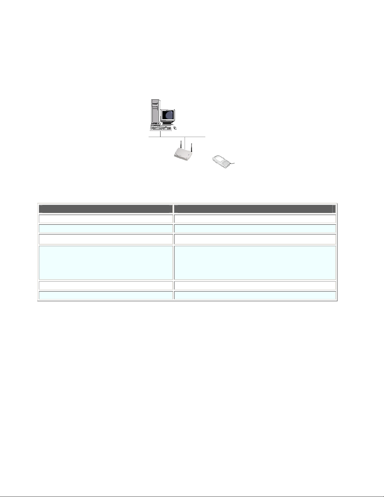
SS method data communication is performed using a wireless card.
Wireless communication between the host computer and BHT is performed via an access point. Please refer to
the “BHT-400B-CE/400BW-CE User’s Manual” for further details.
The table below shows the wireless communication devices on the BHT-400 and communication state transition
for the above system configuration.
Wireless Communication Device Status Communication
Open (power on) Impossible
Checking synchronization with access point Impossible
Synchronization complete Possible
Impossible:
Roaming
Roaming complete Possible
Close (power off) Impossible
The wireless communication device will consume a significant amount of power if always open. The device should
therefore be closed as much as possible when not in use.
It will, however, take several seconds until the wireless communication device is ready to perform communication
after being opened. Frequent opening and closing of the device will require much time, resulting in poor
responsiveness. The application purposes of user programs should be taken into account when programming.
When the wireless communication device is synchronized with the access point, the BHT displays a
synchronization icon at the LCD screen.
If the BHT is not synchronized with an access point.
Possible:
If synchronization with an access point is maintained.
- 8 -
Page 15
5.2. Wireless Communication Parameters
Make the following system settings in order to establish the wireless communication pathway.
• ESSID (Extended Service Set ID)
Can be set from the ZeroConfig menu or in the user program.
• POWER
Can be set from the System menu or in the user program.
When making the settings in the System menu, please refer to the “BHT-400B-CE/400BW-CE User’s Manual” for
further details.
When no settings are made at the user program, the system settings set at the ZeroConfig menu or in the System
menu are used as is.
ESSID
Specify a character string for the ID used over the wireless network. Set the same ID as the SSIS for the
access point used for communication. Communication will not be possible if set incorrectly.
[Ex.] ”BHT400" is set for the ESSID.
MyProfile. SSID = “BHT400”
POWER
It is possible to set the power mode for the BHT wireless module. The following two power modes are
available. The default is EN_POWERSAVE.CAM.
Power Mode
Power Consumption Status
CAM(Continuously Access Mode) Max. power consumption
PSP(Power Saving Polling) Min. power consumption
[Ex.] Set the power mode to "Consumes much power".
RF.Settings.PowerSave = RF.Settings.EN_POWERSAVE.CAM
- 9 -
Page 16
5.3. Security
The BHT can be used with following security configurations.
• PEAP (802.1x)
• EAP-TLS (802.1x)
• PEAP (WPA)
• EAP-TLS (WPA)
• PSK (WPA)
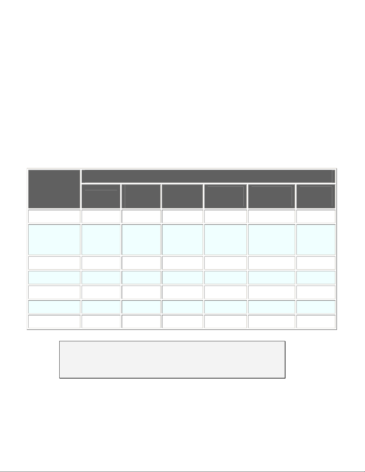
Details of the parameters used with the above security configurations are outlined in the table below.
(●: Setting enabled, –: Setting disabled)
Security
Parameter
None
PEAP
(802.1x)
EAP-TLS
(802.1x)
PEAP
(WPA)
EAP-TLS
(WPA)
PSK
(WPA)
Authentication Open Open Open WPA WPA WPA-PSK
Encryption
Disable
WEP(static)
WEP
(auto
distribution)
WEP
(auto
distribution)
TKIP TKIP TKIP
802.1x Disable PEAP EAP-TLS PEAP EAP-TLS Disable
ESSID ● ● ● ● ● ●
Profile Priority ● ● ● ● ● ●
Pre-shared Key
WEP Key ●
– – – – –
– – – – –
–
[Ex.] Settings required to connect to network using PEAP(802.1x):
MyProfile.Authentication = RF.Profile.EN_AUTHENTICATION.OPEN
MyProfile.Encryption = RF.Profile.EN_ENCRYPTION.WEP
MyProfile.EAP8021x = RF.Profile.EN_EAP8021X.PEAP
- 10 -
Page 17

5.4. Programming
The programming procedure required to connect to the network is as follows.
1. Select the profile to be edited.
Use ESSID and Infrastructure to specify the profile.
A new profile is created if no profile applicable to the specified ESSID and Infrastructure combination exists.
2. Change parameter 1, parameter 2, ……parameter N for the selected profile.
3. Reflect the set parameters to the driver.
4. Open the wireless device.
5. Check synchronization with the AP (*1).
(*1) The following is a list of possible reasons why it may not be possible to obtain synchronization with the
AP.
• The wireless communication device is preparing to open.
Several seconds are required to open the wireless communication device and obtain
synchronization with the access point. Furthermore, there are times when several tens of
seconds are required to connect to the network and acquire the IP when using DHCP.
• The BHT is moving from the current access point to the next access point by roaming.
• The BHT has been moved to a location outside the range of the AP.
• The BHT has been moved to a location where an obstacle exists that prevents wireless
communication with the AP.
- 11 -
Page 18

6. Backlight
The backlight function has the following features.
• Backlight control
• Backlight control key specification
• Backlight illumination duration specification
• Brightness adjustment
• Backlight OFF/DIM toggle
- 12 -
Page 19
6.1. Backlight Control
The backlight can be controlled using the following methods.
• Control by pressing the backlight function control key
• Control using the backlight control property
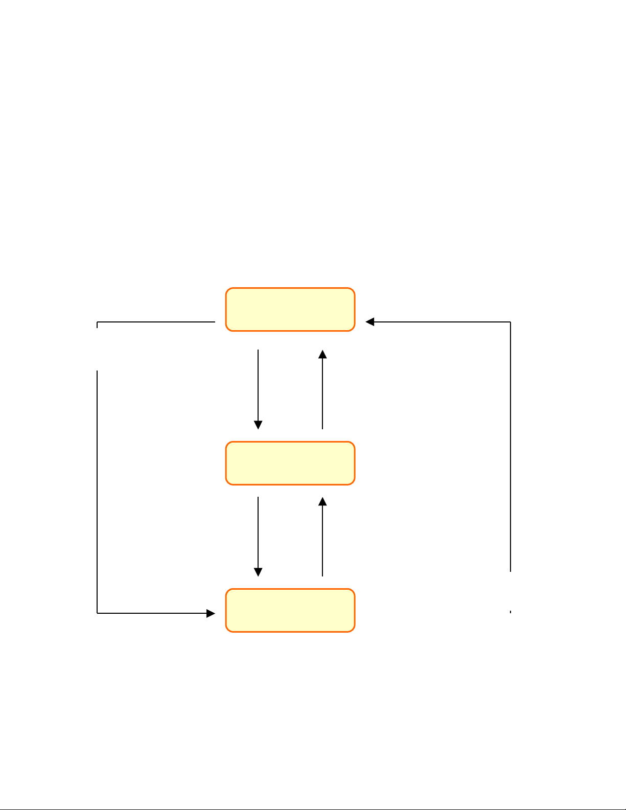
The backlight function can be enabled/disabled by pressing the backlight function control key (Default: Hold down
[SF] key and press [M4].).
With the backlight function enabled, press any key or tap the touch panel to turn the backlight ON.
If a key is not pressed or the touch panel is not tapped within the backlight illumination duration, the backlight
function remains enabled, however the backlight itself will turn OFF or dim.
The backlight illumination status can be controlled by entering a value at the Backlight.Status property, regardless
of whether it is currently disabled or disabled. Furthermore, the illumination status can be acquired by reading the
property value.
Press backlight function control key,
Status = ENABLE_ON
or
Status = ENABLE_OFF
Press key other than backlight
function control key or tap
touch panel,
or
Status = ENABLE_ON
Disabled
Enabled, OFF/DIM
[Default Status]
Enabled, ON
Press backlight function control key,
or
Status = DISABLE_OFF
Illumination duration elapses
since key last pressed or touch
panel tapped,
or
Status = ENABLE_OFF
Press backlight function control key,
or
Status = DISABLE_OFF
- 13 -
Page 20

6.2. Backlight Control Key
The backlight function control key can be specified with the Backlight.Settings.CtrlKey property. The backlight is
controlled by holding down the [SF] key and pressing [M4] by default. Furthermore, the current backlight control
key can be acquired by reading the property value.
Backlight Control Key Setting Backlight Control Key Setting
[SF] + [.] 0x0001000A
[SF] + [BS] 0x0001000B
[SF] + [C] 0x0001000C
[F1] 0x00000101
[F2] 0x00000102
[F3] 0x00000103
[F4] 0x00000104
[F5] 0x00000105
[F6] 0x00000106
[F7] 0x00000107
[F8] 0x00000108
[F9] 0x00000109
[F10] 0x0000010A
[F11] 0x0000010B
[F12] 0x0000010C
[SCAN] 0x00000200 [SF] + [SCAN] 0x00010200
[M1] 0x00000201 [SF] + [M1] 0x00010201
[M2] 0x00000202 [SF] + [M2] 0x00010202
[M3H] (half-press) 0x00000243 [SF] + [M3H] (half-press) 0x00010243
[M3] 0x00000203 [SF] + [M3] 0x00010203
[M4H] (half-press) 0x00000244 [SF] + [M4H] (half-press) 0x00010244
[M4] 0x00000204 [SF] + [M4] 0x00010204
- 14 -
Page 21

6.3. Backlight Illumination Duration
The backlight illumination duration time can be set at or acquired from the Backlight.Settings.OnTimeBattery
/OnTimeACTime property when the backlight is powered by the battery or when the BHT is installed on the CU.
The illumination duration default value is 3 seconds when powered by the battery, and 60 seconds when installed
on the CU.
The illumination duration begins from the moment all keys or the touch panel is released.
6.4. Brightness
The brightness when the backlight turns ON can be set at or acquired from the Backlight.Settings.Brightness
property.
The backlight brightness can be selected from the following four levels:
0 (OFF), 1 (dark) to 3 (bright) (Default: 3)
6.5. OFF/DIM Toggle
It is possible to set or acquire whether the backlight turns OFF completely or dims when not lit at the
Backlight.Settings.PowerSave property.
Default: DIM
The Backlight.Status property should be ENABLE_OFF (OFF/dimmer) or DISABLE (disabled) in either case.
- 15 -
Page 22
7. Beeper, Vibrator
The beeper and vibrator function is equipped with the following features.
• The beeper or vibrator is selected and the beeper volume setting made at the system settings.
• Sound pattern specification
7.1. Beeper/Vibrator Selection
It is possible to select from “Beeper only”, “Vibrator only”, and “Beeper and vibrator”.
Sounding of the beeper or activation of the vibrator from the application is controlled using an indexer. The beeper
or vibrator is specified for the index.
[Ex.] Sound beeper only.
[VB] MyBeep.Item(Beep.Settings.EN_DEVICE.BEEP) = Beep.EN_CTRL.ON
[C#] MyBeep[Beep.Settings.EN_DEVICE.BEEP] = Beep.EN_CTRL.ON
例) Sound beeper and vibrator.
[VB] MyBeep.Item(Beep.Settings.EN_DEVICE.BEEP Or _
Beep.Settings.EN_DEVICE.VIBRATOR) = Beep.EN_CTRL.ON
[C#] MyBeep[Beep.Settings.EN_DEVICE.BEEP
| Beep.Settings.EN_DEVICE.VIBRATOR] = Beep.EN_CTRL.ON
Specify whether to sound the beeper or activate the vibrator when displaying a warning message and so forth
upon the completion of barcode reading at the Beep.Settings.Device property.
7.2. Beeper, Vibrator Parameters
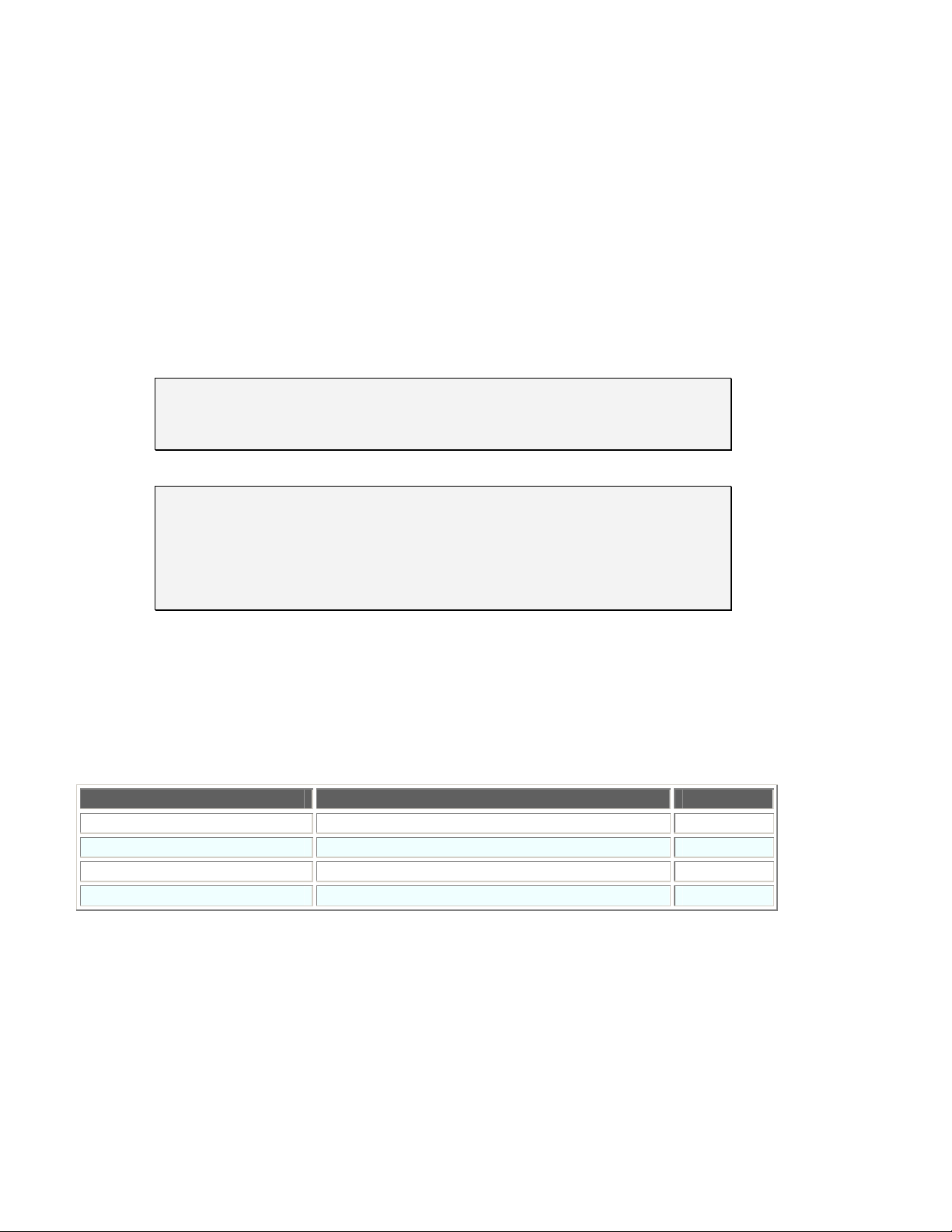
The beeper and vibrator parameters are listed in the following table.
Parameter Setting Default
ON duration (/100 msec) 0 to 255 5
OFF duration (/100 msec) 0 to 255 5
Frequency (beeper only) 39 to 32767Hz, 0:698Hz, 1:1396 Hz, 2:2793Hz 2
Repeat count (times) 0 to 255 1
The beeper or vibrator will remain ON continuously if the ON duration is set to a value other than “0” and the OFF
duration is set to “0”.
- 16 -
Page 23
7.3. Beeper Volume
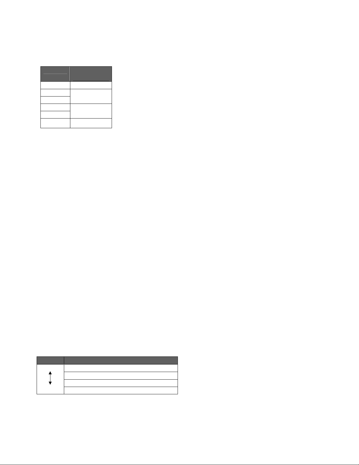
The beeper volume level can be selected from the six levels shown in the table below, however, there are in fact
only four levels; OFF, Low, Medium and High.
Setting Volume
Level
0 OFF
1
2
3
4
5
When sounding the beeper from the application, the volume setting is valid only when the frequency is set to “0”,
“1”, or “2”.
The beeper will sound at maximum volume at all other frequency settings.
The key click sound, half-press key click sound, and touch panel tap sound volume can also be controlled from the
application. The volume for each of these sounds is set at the Beep.Settings.VolumeKey,
Beep.Settings.VolumeHalfKey, and Beep.Settings.VolumeTap property items, respectively, and can be set to
“OFF”, “Low”, or “High”.
Furthermore, it is possible to turn the click sound ON or OFF for individual magic keys (full or half-press) set for
trigger keys and marker keys. The value set at the Beep.Settings.VolumeKey/VolumeHalfKey properties is used
only when set to “ON”. The default click sound for magic keys (full or half-press) set for trigger keys and marker
keys is “OFF”.
Low
Medium
High
7.4. Beeper and Vibrator Control
The beeper sounding or vibrator activation is called up asynchronously, the process is returned to the application
immediately after the setting is made, and the beeper or vibrator operates in the background.
7.5. Priority Order
The priority order for sounding the beeper or activating the vibrator is set for each event.
If an activation request is received when a high-priority event occurs while the beeper/vibrator is currently
activated due to a low-priority event, the beeper/vibrator for the low-priority event is stopped, and the
beeper/vibrator is activated for the high-priority event.
If an activation request is received when a low-priority event occurs while the beeper/vibrator is currently activated
due to a high-priority event, the beeper/vibrator for the low-priority event is ignored, and the process is returned.
Priority Events That Activate Beeper/Vibrator
High
Low
System error
Completion of barcode reading
Setting in applications
Key clicks or screen taps
- 17 -
Page 24

8. Battery Information
The battery information function provides the following information.
• Battery voltage (mV)
• CU installation status (charge status)
• Battery level
• Battery type
There are six battery levels.
The battery level is “HIGH” when fully charged and continues to drop to “MID” and then “LOW” and so on as the
BHT is used.
If a key is pressed or the touch panel is tapped when the battery level is “LOW”, the beeper will sound three times
and a ”Battery voltage low” message displays. This message will not display again until the BHT is next
suspended or resumed.
If use of the BHT is continued even when the battery voltage is low, the beeper will sound five times, a “Please
recharge battery.” message displays, and the BHT automatically goes into suspend mode. It will then not be
possible to resume the BHT until the battery has been sufficiently charged.
Level Voltage
HIGH 3.9 V or above
MID Less than 3.9 V
LOW Less than 3.7 V (Beeper sounds once and message displays.)
WARNING Less than 3.6 V (Beeper sounds three times, message displays, and BHT
suspended automatically.)
CRITICAL Less than 3.4 V (BHT does not operate.)
NO_BATTERY No battery installed (BHT does not operate.)
The actual battery voltage may differ depending on how the BHT is used. Barcode reading and wireless
communication and so forth exert a large load on the battery and therefore the voltage level may display lower
than the actual level at such times. A message displays and the BHT switches to suspend mode at such times
also.
Ensure to always use a lithium-ion battery.
- 18 -
Page 25
9. Keyboard
The following key functions exist in addition to the standard press/release functions.
• Input mode change
• Magic key function assignment
• [SF] key operation mode change
9.1. Input Mode Change
The following input modes are available.
• Numeric entry mode (default), function mode (*1)
By pressing the [FUNC] key, an icon displays and the mode changes to Function mode, however, the
operation for the returned virtual key codes and display characters does not change.
• Alphabet entry mode
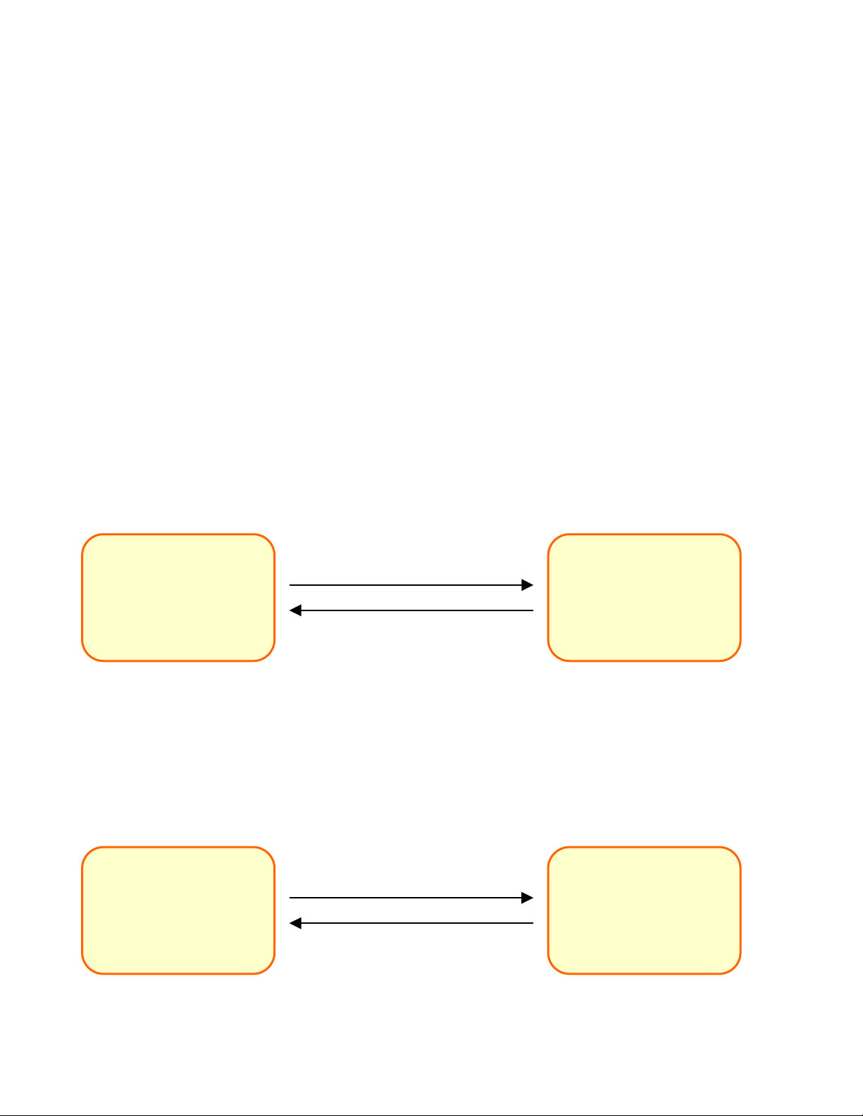
Change to alphabet entry mode by pressing the [ALP] key or by enabling the Keys.Settings.InputMethod property.
Changing the input mode using the [ALP] key can be prohibited using the Keys.Settings.AllowChangeIM property.
Numeric entry mode
[Default]
EN_ INPUT_METHOD.ALPHABET
EN_ INPUT_METHOD.NUMERIC
9.2. Function Mode
The function mode can be changed by pressing the [FUNC] key or enabling the Keys.Settings.FuncMode property.
The virtual key codes and display characters returned when keys are pressed in function mode are shown in
“Appendix 2. Virtual Keyboard and Display Characters”.
Numeric entry mode
[Default]
EN_FUNC_MODE.NONFUCTION
Press [ALP] key,
or
Keys.Settings.InputMethod =
Alphabet entry mode
Press [ALP] key,
or
Keys.Settings.InputMethod =
Press [FUNC] key,
or
Keys.Settings.FunMode =
EN_FUNC_MODE.FUCTION
Function mode
Press [FUNC] key,
or
Keys.Settings.FuncMode =
- 19 -
Page 26

9.3. Numeric Entry Mode
The virtual key codes and display characters returned when keys are pressed in numeric entry mode are shown in
“Appendix 2. Virtual Keyboard and Display Characters”.
9.4. Alphabet Entry Mode
With the 31-key type BHT-400, it is only possible to use the keys to enter alphabet characters when in this input
mode.
The virtual key codes and display characters returned when keys are pressed in alphabet entry mode are shown
in “Appendix 2. Virtual Keyboard and Display Characters”.
Entry Method
Alphabet characters are entered in a way similar to that on mobile phones. When changing to alphabet entry mode,
an unestablished character display window similar to that shown below displays. When the key for the alphabet
character to be entered is pressed, the character displays in this window as an unestablished character. When the
alphabet character to be entered displays in this window, it is established, and the alphabet character is actually
entered.
■ The focus is not transferred.
■ The window always displays in the foreground.
■ The window can be moved by using the stylus.
■ “SP” displays when the unestablished character is a space.
Unestablished character establishment method
Press any of the following keys to establish unestablished characters.
• [0] to [9], [.] keys that differ from key pressed at unestablished character
• [ENT] key
• [MAGIC_FUNC_ENTER] assigned to [M1], [M2], [M3], [M3H], [M4], [M4H], [M5], [M5H], and [SCAN] keys
• [F1] to [F12] keys
- 20 -
Page 27
Keys used for alphabet entry mode
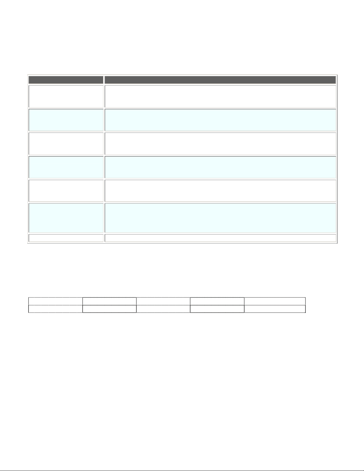
The table below lists keys whose operations are different from those in the numeric entry mode.
Key Description
[0] to [9] and period [.]
keys
Used to enter alphabet characters. The alphabet characters assigned to each key
are based on the character codes in “Appendix 2. Virtual Keyboard and Display
Characters”.
Establishes unestablished keys if any exist.
[ENT] key
If there are no unestablished keys, the same character code as that for the
numeric entry mode is returned.
Clears unestablished keys if any exist.
[BS] key
If there are no unestablished keys, the same character code as that for the
numeric entry mode is returned.
Clears unestablished keys if any exist.
[C] key
If there are no unestablished keys, the same character code as that for the
numeric entry mode is returned.
[F1] to [F12] keys Establishes unestablished keys if any exist.
If there are no unestablished keys, the same character code as that for the
numeric entry mode is returned.
M1, M2, M3H, M3, M4H,
M4, M5H, M5, and
[SCAN] keys
Establishes unestablished keys if any exist when MAGIC_FUNC_ENTER is
assigned to these keys.
If there are no unestablished keys, the same character code as that for the
numeric entry mode is returned.
[ALP] key Clears unestablished keys if any exist and switches to numeric entry mode.
9.5. Magic Key Operation
Magic key function assignment
The following functions are assigned to magic keys.
None [ENT] key Trigger key [SF] key Backlight control
Marker light [CTL] key [ALT] key [TAB] key CLEAR key
- 21 -
Page 28
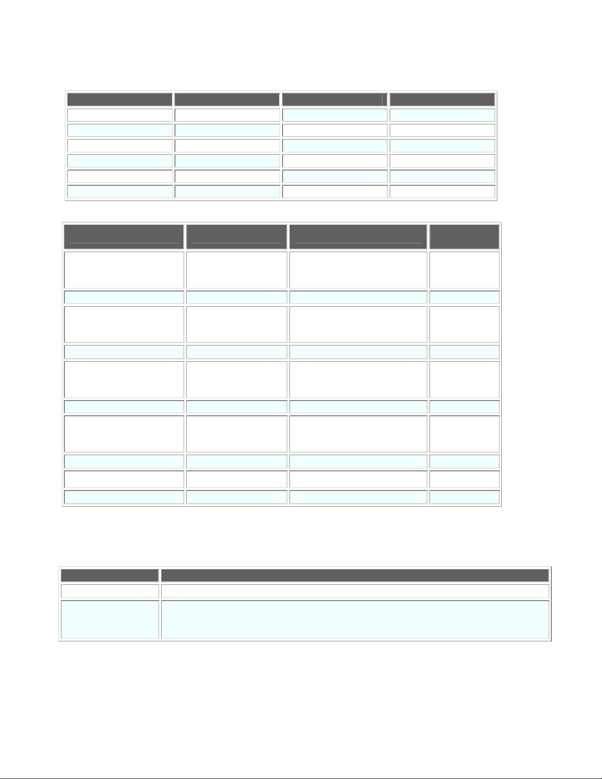
The default functions for each magic key are as follows.
Key Default Function Key Default Function
[M1] [TAB]
[M2] None
[M3] Trigger [M3H] Marker light
[M4] Trigger [M4H] Marker light
[M5] Trigger [M5H] Marker light
[SCAN] Trigger
The virtual key codes and display characters returned when functions are assigned to magic keys are as follows.
Parameter Function Virtual Key Code
MAGIC_FUNC_NONE None Keys.M1 to Keys.M5,
Keys.M3H to Keys.M5H
Keys.Scan
MAGIC_FUNC_ENTER [ENT] Keys.Return 0D(H)
MAGIC_FUNC_TRG Trigger Keys.M1 to Keys.M5,
Keys.M3H to Keys.M5H
Keys.Scan
MAGIC_FUNC_SHIFT [SF] Keys.Shift
MAGIC_FUNC_BLT Backlight control Keys.M1 to Keys.M5,
Keys.M3H to Keys.M5H
Keys.Scan
MAGIC_FUNC_TAB [TAB] Keys.Tab 09(H)
MAGIC_FUNC_LASER Marker light Keys.M1 to Keys.M5,
Keys.M3H to Keys.M5H
Keys.Scan
MAGIC_FUNC_CTRL [CTRL] Keys.Control
MAGIC_FUNC_ALT [ALT] Keys.Menu
MAGIC_FUNC_CLEAR CLEAR Keys.Clear
9.6. Shift Key Operation
Character
Code
−
−
−
−
−
−
−
The following two shift key ([SF]) operation modes are available.
Operation Mode Description
Normal
• Shift status when [SF] key pressed
• Shift status not only when the [SF] key is held down but also while the next key
Onetime lock
(except the trigger switch) is pressed and released after the [SF] key is released.
• The trigger switch does not act as a [SF] key.
- 22 -
Page 29
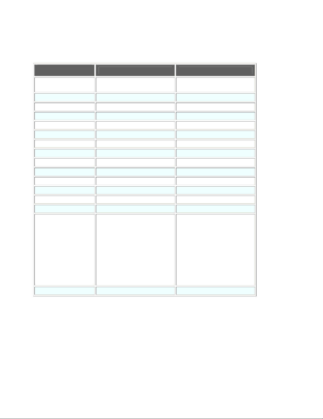
9.7. Auto Repeat Function
The key auto repeat function is activated when a single key is held down continuously. The following table shows
the list of valid keys and invalid keys for the auto repeat function.
Key
[0] to [9] and period [.]
keys
[A] to [Z] keys
[SP] key ([SF] + [BS])
[BS] key
[C] key
Arrow keys
• In numeric entry mode:
• In alphabet entry mode:
31-key Type 50-key Type
●
●
–
– ●
● ●
● ●
● ●
● ●
[F1] to [F12] keys ● ●
[SF] key – –
[Func] key
– –
[ENT] key – –
[TAB] key ● ●
[SEND] key – –
[ALP] key – –
[SCAN] key
Magic keys
Same as magic key Same as magic key
• No key assignment. :
•
[ENT] key : –
• Trigger key :
• [SF] key :
• Backlight ctl key :
[TAB] key : ●
•
• Laser light key :
• [CTRL] key :
• [ALT] key :
• CLEAR key :
–
–
–
–
–
–
–
–
• No key assignment. :
•
[ENT] key : –
• Trigger key :
• [SF] key :
• Backlight ctl key :
[TAB] key : ●
•
• Laser light key :
• [CTRL] key :
• [ALT] key :
• CLEAR key :
–
–
–
–
–
–
–
–
[PW] key – –
●: Auto repeat, –: No auto repeat
9.8. Keyboard Type
There are two types of keyboard; a 31-key type and a 50-key type. The keyboard type can be acquired from the
application.
- 23 -
Page 30
s
s
s
s
s
s
s
s
10. LED
The BHT has two LEDs, a display LED (red/blue) to notify the operator that barcode reading is complete, and a
charge LED (red/green) to notify the operator of the charge status.
The illumination status for the display LED can be controlled from the application.
The illumination status is set and acquired using a 2D indexer. The illumination device (display (barcode) LED only
on BHT-400) is specified for the first index, and the illumination color (red or green) is specified for the second
index.
[Ex.] Turn ON the red display LED.
[VB] MyLED. (LED.EN_DEVICE.BAR,LED.EN_COLOR.RED) _
= LED.EN_CTRL.ON
[C#] MyLED[LED.EN_DEVICE.BAR,LED.EN_COLOR.RED]
= LED.EN_CTRL.ON
The priority order relationship is as follows:
(Barcode read based control) > (application based control)
If “Turn ON LED when barcode reading complete.” is specified and barcode reading is enabled, the display LED
illumination status cannot be controlled from the application until barcode reading is next disabled.
The illumination request from the application, however, is retained in the variable flag (RAM) inside the LED driver.
Illumination requests are also set and cleared while barcode reading is enabled. When barcode reading is
disabled, the flag is checked and the LED color for which an illumination request exists is turned ON automatically.
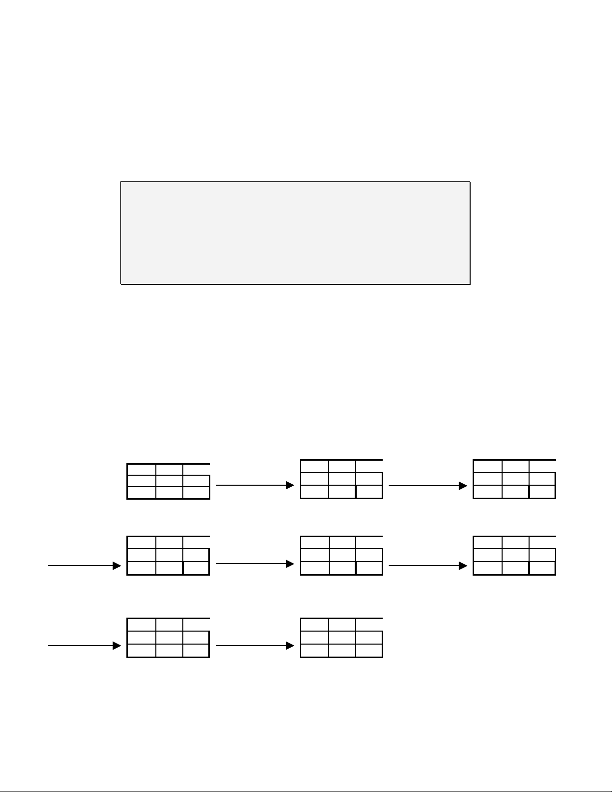
[Ex.]
[Default status]
Red Green
Statu
OFF OFF
Rqst. No No
Red LED ON
specified from
application.
Statu
Rqst. Yes No
Red Green
ON OFF
Reading enabled
Statu
Rqst. Yes No
Red Green
OFF OFF
Blue LED ON
specified from
application.
Reading disabled
Statu
Rqst. Yes Yes
Statu
Rqst. No Yes
Blue LED ON
Red Green
ON ON
Red Green
OFF ON
Reading enabled
Statu
Rqst. Yes Yes
Red Green
OFF OFF
Reading disabled
Red LED OFF
specified from
application.
Red Green
Statu
Rqst. Yes No
ON OFF
Red LED ON
Red Green
Statu
OFF OFF
Rqst. No Yes
- 24 -
Page 31

The red LED is shared with the charge LED and turns ON in either of the following situations.
1. The red LED is turned ON from the application.
2. While the BHT is charging
If, therefore, an attempt is made to turn OFF the red LED from the application while charging, the LED will remain
ON.
- 25 -
Page 32

11. Power Management
The four power statuses are listed in the table below.
CPU
LCD ON ON OFF OFF
(*1) No processing is performed when the BHT is on standby. Furthermore, ensure to disable standby before
accessing the card.
(*2) The events that cause the BHT to switch to the suspend and critical OFF statuses differ. The BHT status when
the power is turned OFF by pressing the power key or when using the auto OFF function is referred to as
“Suspend”, and the status when the power turns OFF due to low battery voltage or when the battery cover lock is
released is referred to as “Critical OFF”.
The power status and power consumption relationship is as follows.
(Power ON) > (Standby) > (Suspend) = (Critical OFF)
11.1. Standby Transition Conditions
The BHT switches to standby when the event that prohibits standby has been completed, and the standby
transition time has elapsed.
Events that prohibit standby
Power ON Standby (*1) Suspend (*2) Critical OFF(*2)
TURBO RUN
/ RUN / IDLE
DEEP IDLE SLEEP SLEEP
- Keyboard being used
- Touch panel being tapped
- Screen display being refreshed
- Beeper/vibrator activated
- Click sound activated
- Backlight ON
- Barcode being read
- Wireless communication open
- IrDA connection open
- USB connection open
- Data being deleted from or written to flash memory
- RTC being accessed
- Display LED ON
- A system message is displayed
The standby transition time can be set or acquired using the PwrMng.Settings.StandbyTime property. Transition to
standby can be prohibited by setting this property to “0”.
- 26 -
Page 33
11.2. Suspend Transition Conditions
The BHT switches to suspend when the power key is pressed, when the event that prohibits suspend has been
completed and the auto power OFF time has elapsed, and when the method used to switch to suspend is called
from the application.
Events that prohibit suspend
- Wireless connection open (Excludes BHT-400 models used in USA and Canada.)
- IrDA connection open
- Connector communication being performed
- Key being pressed
- Touch panel being tapped
The auto power OFF time when the BHT is powered by the battery and when it is installed on the CU can be set or
acquired at the PwrMng.Settings.AutoPowerOffBattery and AutoPowerOffExt properties, respectively. Auto power
OFF can be disabled by setting this property to “0”.
It is also possible to switch to suspend from the application by calling up the PwrMng.Shutdown method.
Furthermore, operation after the transition to suspend can be specified by setting the parameters for the methods.
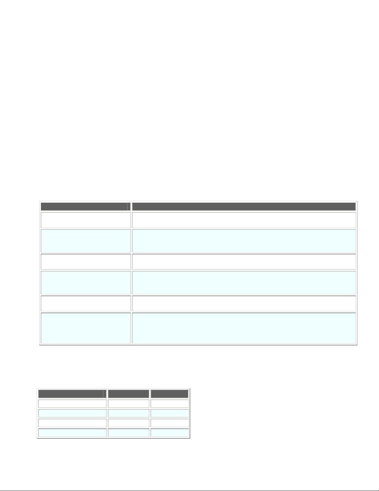
Parameter Description
WARM
SUSPEND
COLD_BOOT_REGINIT
COLD_BOOT_REGREMAIN
SYSMODIFY
COLD
Warm boot is performed after power OFF. There is no need to turn the
power ON, the contents of the RAM are retained.
The BHT switches to suspend. Press the power key to turn ON the power.
The contents of the RAM are retained provided that the sub-battery does
not become fully discharged.
The BHT cold boots automatically after power OFF. The contents of the
RAM are deleted, and the registry is reinitialized.
The BHT cold boots automatically after power OFF. The contents of the
registry at this time are saved, and then restored when the BHT is started
up.
The BHT cold boots automatically after power OFF, and the consecutive
RAM allocation is maintained.
The BHT cold boots automatically after power OFF,. If the registry has been
saved, the BHT is booted based on the values for that registry, however, if it
has not been saved, the BHT is booted based on the values for the default
registry value.
Warm boot and cold boot
The memory contents retention status differs between warm boot and cold boot.
Warm Boot Cold Boot
Files in flash memory ● ●
Files in RAM ● –
Data being edited – –
Registry information ● – (*1)
(*1) If the registry is saved, the information is restored to the values at the point it is saved.
- 27 -
Page 34

12. Updating the OS
The system can be updated (version update) by creating and executing the update applications discussed in the
procedure below while Windows CE is running.
Update method using RAM
(1) Call up the PwrMng.Shutdown(PwrMng.EN_SHUTDOWN_MODE.SYSMODIFY) method and reboot the
BHT (*1).
(2) After rebooting, a “SysModify” directory (RAM disk) is created. Copy the OS file to this directory.
(3) Specify the update filename in the SysModification.FileName property.
(4) Call up the SysModification.Execute method to update the OS.
(5) The power turns OFF automatically after the update procedure is complete (The BHT cold boots and the
registry is initialized the next time the power is turned ON.)
Update method using CF memory card
(1) Call up the PwrMng.Shutdown(PwrMng.EN_SHUTDOWN_MODE.SYSMODIFY) method and reboot the
BHT (*1).
(2) Save the OS file to the CF memory card and insert the card in the BHT-400 CF slot.
(3) Perform steps (3) to (5) above for the “Update method using RAM”.
(*1) After rebooting, the RAM usage allocation is decreased by approximately 32 MB in order to ensure that
the system secures approximately 32 MB for updating the OS.
- 28 -
Page 35
13. Status Display
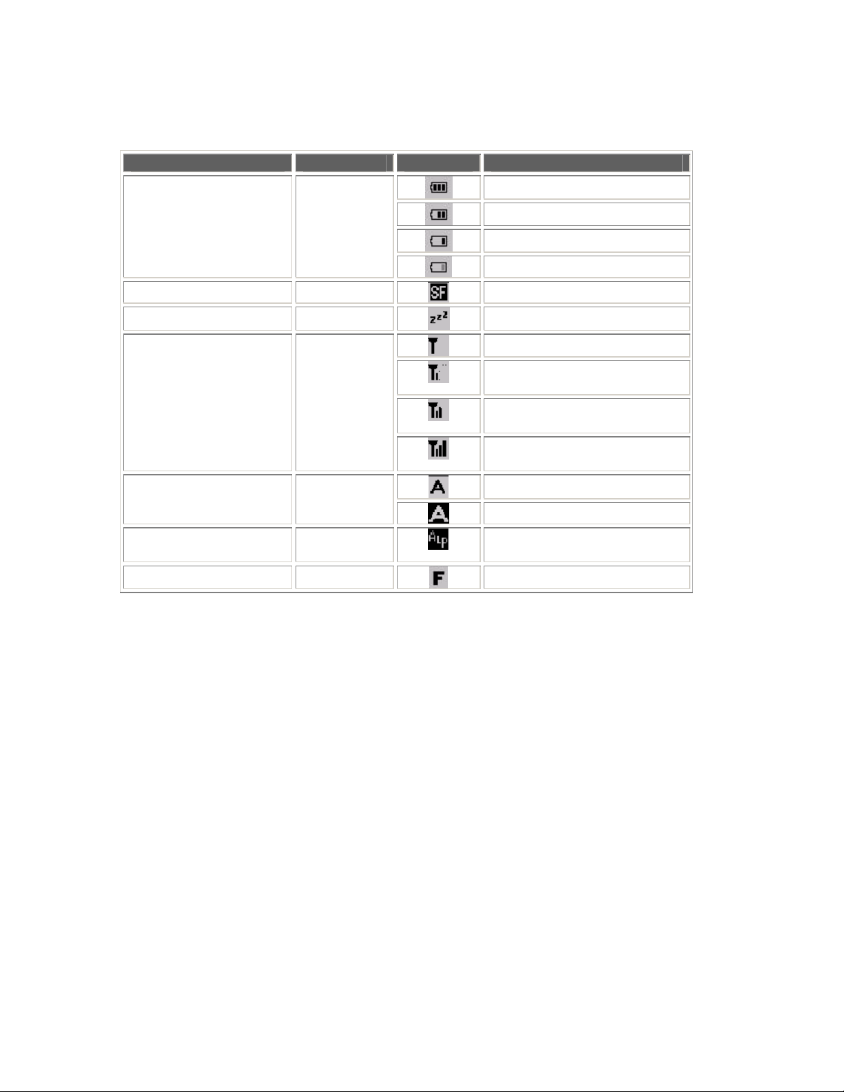
Enabling and disabling of the following status display icons can be controlled from the application.
Property Icon Meaning
High 3.9 V or more
Residual battery
voltage
[SF] key Shift Key
Standby transition Standby
Wireless
communication
SIP SIP
Alphabet entry Alphabet
Function mode Func
Battery
Wireless
Medium Less than 3.9 V
Low Less than 3.7 V
Warning Less than 3.6 V
[SF] key pressed
Switching to standby
Wireless connection open
Radio field intensity: Low
Synchronous connection
Radio field intensity: Medium
Synchronous connection
Radio field intensity: High
Synchronous connection
Starting up SIP input.
Awaiting SIP input.
Currently in alphabet entry
mode
Currently in function mode
- 29 -
Page 36

14. System Information
The following system information can be acquired from the BHT.
• System version
• Machine name
• Machine No.
• Serial No.
• RAM size
• ROM size
The RAM and ROM size constitute the size of the BHT memory. This does not refer to the amount of available
space or user space.
- 30 -
Page 37
15. Data Communication
The following communication interfaces can be used for communication with the host computer. Of the three listed
below, the IrDA interface and connector interface can be used with the CommSerial class and FileTransfer class in
order to create applications.
• IrDA interface (IrDA-SIR1.2)
• Connector interface
• USB interface
15.1. IrDA Interface
The IrDA interface is assigned to port no. 4.
Communication
Parameter
Transmission
speed (bps)
The IrDA interface conforms to an IrDA physical layer (IrDA-SIR1.2), and therefore parameters other than
transmission speed are all fixed (vertical parity = none, character length = 8 bits, stop bit length = 1 bit).
15.2. Connector Interface
The connector interface is assigned to port no. 1.
Communication
Parameter
Transmission
speed (bps)
Vertical parity None, even number, odd number None
Data length 7 bits, 8 bits 8
Stop bit length 1 bit, 2 bits 1
15.3. File Transfer
115200, 57600, 38400, 19200, 9600 9600
115200, 57600, 38400, 19200, 9600, 4800, 2400, 1200, 600, 300 9600
Setting Default
Setting Default
The FileTransfer class can be used to create a file transfer application using Y-modem communication.
In addition to the file itself, the “filename” and “file update date” are also transferred. If, however, the application at
the computer side is not compatible with the file update date, the transfer time will be set for both uploading and
downloading.
15.4. ActiveSync Auto Connection
The ActiveSync auto connection function can be enabled or disabled from the application.
This can be set for each communication interface.
The default value for all communication interfaces is “Disabled”.
The CU-421 is required for ActiveSync auto connection using IrDA.
- 31 -
Page 38

16. Namespaces
The following three namespaces exist in the BHT-400 class library.
Namespace Name Description
DNWA.BHTCL Class group used to realize functions unique to
the BHT-400.
DNWA.Exception Thrown exception class group.
DNWA.Tools.BHT.Communication File Transfer, Serial Communication
- 32 -
Page 39

17. Class
DNWA.BHTCL Namespace
The DNWA.BHTCL namespace includes the following classes.
Class Name Description
17.1. Scanner Barcode read control, read results acquisition
17.2. Scanner.CodeInfo Code information
17.3. Scanner.Settings Barcode related system settings
17.4. BatteryCollection Battery collection
17.5. BatteryCollection.Battery Battery information acquisition
17.6. Backlight Backlight illumination control
17.7. Backlight.Settings Backlight related system settings
17.8. LED LED illumination control
17.10. Beep Beeper/vibrator control
17.11. Beep.Settings Beeper/vibrator related system settings
17.12. RF Wireless connection open/close
17.13. RF.Profile Wireless communication profile properties
17.14. RF.Settings Wireless communication related settings
17.15. RF.WepKeyCollection Wep key
17.16. RF.SiteSurvey SiteSurvey information
17.17. RF.Info Wireless device information
17.18. Keys Keyboard related definitions
17.19. Keys.Settings Keyboard related settings
17.22. PwrMng Power management control
17.23. PwrMng.Settings Power management related settings
17.20. SysInfo System information
17.21. SysInfo.Settings System information related system settings
17.24. Icon Dedicated BHT icons
17.25. Icon.Settings Icon display enabled/disabled
17.26. Display Screen control
17.27. Display.Settings Screen control settings
17.28. SysModification OS update
- 33 -
Page 40
DNWA.Exception Namepsace
The DNWA.Exception namespace includes the following classes.
Class Name Description
17.29. ArgumentException An exception thrown when a specified parameter is invalid.
17.30. ObjectDisposedException An exception thrown when an operation request is issued to a
device whose file has not been opened.
17.31. SecurityException An exception thrown when an open request is issued to a device
file for which authorization for opening cannot be obtained (e.g.,
when the file is already opened).
17.32. DeviceNotFoundException An exception thrown when an operation request is issued to a
device that is not installed on the BHT.
17.33. DeviceLoadException An exception that is thrown when an operation request is issued
to a device that is not ready to process it.
17.34. NotSupportedException An exception that is thrown when an attempt is made to carry out
a function that is not supported.
DNWA.Tools.BHT.Communication Namespace
The DNWA.Tools.BHT.Communication namespace includes the following classes.
Class Name Description
17.35. CommSerial Serial communication
17.36. FileTransfer File transfer using Y-modem protocol
- 34 -
Page 41
17.1. Scanner
Controls barcode reading and acquires the read data.
For a description of all members of this class, refer to section “18.1. Scanner".
Syntax
[VB]
Public Class Scanner
[C#]
public class Scanner
Namespace
DNWA.BHTCL
Assembly
DNWA.BHT400CL.dll
- 35 -
Page 42
17.2. Scanner.CodeInfo
Acquires the code information read by the scanner.
This class exists within the Scanner class.
For a description of all members of this class, refer to section “18.2. Scanner.CodeInfo".
Syntax
[VB]
Public Class Scanner.CodeInfo
[C#]
public class Scanner.CodeInfo
Namespace
DNWA.BHTCL
Assembly
DNWA.BHT400CL.dll
- 36 -
Page 43
17.3. Scanner.Settings
Sets or acquires barcode related parameters.
This class exists within the Scanner class.
For a description of all members of this class, refer to section “18.3. Scanner.Settings".
Syntax
[VB]
Public Class Scanner.Settings
[C#]
public class Scanner.Settings
Namespace
DNWA.BHTCL
Assembly
DNWA.BHT400CL.dll
- 37 -
Page 44
17.4. BatteryCollection
Acquires information on the battery such as the charge status and output voltage.
For a description of all members of this class, refer to section “18.4. BatteryCollection".
Syntax
[VB]
Public Class BatteryCollection
[C#]
public class BatteryCollection
Namespace
DNWA.BHTCL
Assembly
DNWA.BHT400CL.dll
- 38 -
Page 45
17.5. BatteryCollection.Battery
Acquires information on the battery such as the charge status and output voltage.
For a description of all members of this class, refer to section “18.5. BatteryCollection.Battery".
Syntax
[VB]
Public Class BatteryCollection.Battery
[C#]
public class BatteryCollection.Battery
Namespace
DNWA.BHTCL
Assembly
DNWA.BHT400CL.dll
- 39 -
Page 46
17.6. Backlight
Sets or acquires the ON/OFF status of the backlight.
For a description of all members of this class, refer to section “18.6. Backlight".
Syntax
[VB]
Public Class Backlight
[C#]
public class Backlight
Namespace
DNWA.BHTCL
Assembly
DNWA.BHT400CL.dll
- 40 -
Page 47
17.7. Backlight.Settings
Sets or acquires backlight related parameters.
This class exists within the Backlight class.
For a description of all members of this class, refer to section “18.7. Backlight.Settings".
Syntax
[VB]
Public Class Backlight.Settings
[C#]
public class Backlight.Settings
Namespace
DNWA.BHTCL
Assembly
DNWA.BHT400CL.dll
- 41 -
Page 48
17.8. LED
Sets or acquires the LED ON/OFF status.
For a description of all members of this class, refer to section “18.8. LED".
Syntax
[VB]
Public Class LED
[C#]
public class LED
Namespace
DNWA.BHTCL
Assembly
DNWA.BHT400CL.dll
- 42 -
Page 49

17.9. LED.UsageCollection
This class is invalid at the BHT-400.
- 43 -
Page 50
17.10. Beep
Controls the beeping of the beeper and vibration of the vibrator.
For a description of all members of this class, refer to section “18.10. Beep".
Syntax
[VB]
Public Class Beep
[C#]
public class Beep
Namespace
DNWA.BHTCL
Assembly
DNWA.BHT400CL.dll
- 44 -
Page 51
17.11. Beep.Settings
Sets or acquires the beeper and vibrator related parameters.
This class exists within the Beep class.
For a description of all members of this class, refer to section “18.11. Beep.Settings".
Syntax
[VB]
Public Class Beep.Settings
[C#]
public class Beep.Settings
Namespace
DNWA.BHTCL
Assembly
DNWA.BHT400CL.dll
- 45 -
Page 52
17.12. RF
Opens and closes wireless communication, and sets or acquires the parameters for wireless communication.
For a description of all members of this class, refer to section “18.12. RF".
Syntax
[VB]
Public Class RF
[C#]
public class RF
Namespace
DNWA.BHTCL
Assembly
DNWA.BHT400CL.dll
- 46 -
Page 53
17.13. RF.Profile
Sets or acquires properties for the wireless communication profile.
This class exists within the RF class.
For a description of all members of this class, refer to section “18.13. RF.Profile".
Syntax
[VB]
Public Class RF.Profile
[C#]
public class RF.Profile
Namespace
DNWA.BHTCL
Assembly
DNWA.BHT400CL.dll
- 47 -
Page 54
17.14. RF.Settings
Sets or acquires the parameters for wireless communication.
This class exists within the RF class.
For a description of all members of this class, refer to section “18.14. RF.Settings".
Syntax
[VB]
Public Class RF.Settings
[C#]
public class RF.Settings
Namespace
DNWA.BHTCL
Assembly
DNWA.BHT400CL.dll
- 48 -
Page 55
17.15. RF.WepKeyCollection
Specifies the Wep key.
This class exists within the RF class.
For a description of all members of this class, refer to section “18.15. RF.WepKeyCollection".
Syntax
[VB]
Public Class RF.WepKeyCollection
[C#]
public class RF.WepKeyCollection
Namespace
DNWA.BHTCL
Assembly
DNWA.BHT400CL.dll
- 49 -
Page 56
17.16. RF.SiteSurvey
Acquires SiteSurvey data.
This class exists within the RF class.
For a description of all members of this class, refer to section “18.16. RF.SiteSurvey".
Syntax
[VB]
Public Class RF.SiteSurvey
[C#]
public class RF.SiteSurvey
Namespace
DNWA.BHTCL
Assembly
DNWA.BHT400CL.dll
- 50 -
Page 57
17.17. RF.Info
Acquires information on wireless communication.
This class exists within the RF class.
For a description of all members of this class, refer to section ”18.17. RF.Info".
Syntax
[VB]
Public Class RF.Info
[C#]
public class RF.Info
Namespace
DNWA.BHTCL
Assembly
DNWA.BHT400CL.dll
- 51 -
Page 58
17.18. Keys
Sets or acquires keyboard related parameters and defines the magic key.
For a description of all members of this class, refer to section “18.18. Keys".
Syntax
[VB]
Public Class Keys
[C#]
public class Keys
Namespace
DNWA.BHTCL
Assembly
DNWA.BHT400CL.dll
- 52 -
Page 59
17.19. Keys.Settings
Sets or acquires keyboard related parameters.
This class exists within the Keys class.
For a description of all members of this class, refer to section “18.19. Keys.Settings".
Syntax
[VB]
Public Class Keys.Settings
[C#]
public class Keys.Settings
Namespace
DNWA.BHTCL
Assembly
DNWA.BHT400CL.dll
- 53 -
Page 60
17.20. SysInfo
Sets or acquires system information.
For a description of all members of this class, refer to section “18.20. SysInfo".
Syntax
[VB]
Public Class SysInfo
[C#]
public class SysInfo
Namespace
DNWA.BHTCL
Assembly
DNWA.BHT400CL.dll
- 54 -
Page 61
17.21. SysInfo.Settings
Sets or acquires parameters related to the system information.
This class exists within the SysInfo class.
For a description of all members of this class, refer to section “18.21. SysInfo.Settings".
Syntax
[VB]
Public Class SysInfo.Settings
[C#]
public class SysInfo.Settings
Namespace
DNWA.BHTCL
Assembly
DNWA.BHT400CL.dll
- 55 -
Page 62
17.22. PwrMng
Sets or acquires power management related parameters for the BHT and controls the shut down process.
For a description of all members of this class, refer to section “18.22. PwrMng".
Syntax
[VB]
Public Class PwrMng
[C#]
public class PwrMng
Namespace
DNWA.BHTCL
Assembly
DNWA.BHT400CL.dll
- 56 -
Page 63
17.23. PwrMng.Settings
Sets or acquires the parameters for power management.
This class exists within the PwrMng class.
For a description of all members of this class, refer to section “18.23. PwrMng.Settings".
Syntax
[VB]
Public Class PwrMng.Settings
[C#]
public class PwrMng.Settings
Namespace
DNWA.BHTCL
Assembly
DNWA.BHT400CL.dll
- 57 -
Page 64
17.24. Icon
Sets or acquires the icon display status (enabled/disabled).
For a description of all members of this class, refer to section “18.24. Icon".
Syntax
[VB]
Public Class Icon
[C#]
public class Icon
Namespace
DNWA.BHTCL
Assembly
DNWA.BHT400CL.dll
- 58 -
Page 65
17.25. Icon.Settings
Enables or disables the display of icons.
This class exists within the Icon class.
For a description of all members of this class, refer to section “18.25. Icon.Settings".
Syntax
[VB]
Public Class Icon.Settings
[C#]
public class Icon.Settings
Namespace
DNWA.BHTCL
Assembly
DNWA.BHT400CL.dll
- 59 -
Page 66

17.26. Display
This function is not supported.
- 60 -
Page 67

17.27. Display.Settings
This function is not supported.
- 61 -
Page 68
17.28. SysModification
Updates the BHT system program.
For a description of all members of this class, refer to section “18.28. SysModification".
Syntax
[VB]
Public Class SysModification
[C#]
public class SysModification
Namespace
DNWA.BHTCL
Assembly
DNWA.BHT400CL.dll
- 62 -
Page 69
17.29. ArgumentException
An exception that is thrown when the value set in the property or the value of one of the parameters specified in
the method is invalid.
Syntax
[VB]
Public Class ArgumentException
Inherits System.ArgumentException
[C#]
public class ArgumentException : System.ArgumentException
Namespace
DNWA.BHTCL
Assembly
DNWA.Exception.dll
- 63 -
Page 70
17.30. ObjectDisposedException
An exception that is thrown when an operation request is issued to a device whose file has not been opened.
Syntax
[VB]
Public Class ObjectDisposedException
Inherits System.ObjectDisposedException
[C#]
public class ObjectDisposedException
: System.ObjectDisposedException
Namespace
DNWA.BHTCL
Assembly
DNWA.Exception.dll
- 64 -
Page 71
17.31. SecurityException
An exception that is thrown when an open request is issued to a device file for which authorization for opening
cannot be obtained (e.g., when the file is already opened).
Syntax
[VB]
Public Class SecurityException
Inherits System.SecurityException
[C#]
public class SecurityException : System.SecurityException
Namespace
DNWA.BHTCL
Assembly
DNWA.Exception.dll
- 65 -
Page 72
17.32. DeviceNotFoundException
An exception that is thrown when an operation request is issued to a device that is not installed on the BHT.
Syntax
[VB]
Public Class DeviceNotFoundException
Inherits System.IO.FileNotFoundException
[C#]
public class DeviceNotFoundException
: System.IO.FileNotFoundException
Namespace
DNWA.BHTCL
Assembly
DNWA.Exception.dll
- 66 -
Page 73
17.33. DeviceLoadException
An exception that is thrown when an operation request is issued to a device that is not ready to process it.
Syntax
[VB]
Public Class DeviceLoadException
Inherits System.IO.FileLoadException
[C#]
public class DeviceLoadException : System.IO.FileLoadException
Namespace
DNWA.BHTCL
Assembly
DNWA.Exception.dll
- 67 -
Page 74
17.34. NotSupportedException
An exception that is thrown when an attempt is made to carry out a function that is not supported.
Syntax
[VB]
Public Class NotSupportedException
Inherits System.IO.PlatformNotSupportedException
[C#]
public class NotSupportedException
: System.IO.PlatformNotSupportedException
Namespace
DNWA.BHTCL
Assembly
DNWA.Exception.dll
- 68 -
Page 75
17.35. CommSerial
Sets or acquires the parameters for serial communication and performs data communication.
For a description of all members of this class, refer to section “18.29. CommSerial".
Syntax
[VB]
Public Class CommSerial
[C#]
public class CommSerial
Namespace
DNWA.Tools.BHT.Communication
Assembly
DNWA.Tools.BHT.Communication400.dll
- 69 -
Page 76
17.36. FileTransfer
Controls the uploading and downloading of files using the Y-modem protocol.
For a description of all members of this class, refer to section “18.30. FileTransfer"
Syntax
[VB]
Public Class FileTransfer
[C#]
public class FileTransfer
Namespace
DNWA.Tools.BHT.Communication
Assembly
DNWA.Tools.BHT.Communication400.dll
- 70 -
Page 77
18. Members
18.1. Scanner
Constructor
Constructor Name Description
Scanner Creates a new instance of the Scanner class.
Fields
Field Name Description
MAX_BAR_LEN Maximum number of digits in barcode
MAX_2DCODE_LEN Maximum number of digits in 2D code
ALL_BUFFER Used to acquire the contents of the entire buffer by the Input method
Properties
Property Name Description
RdMode Read mode
RdType Read-enabled codes
PortOpen Read-enabled/read-disabled
InBufferCount Number of code digits in the barcode in the buffer
InBufferType Type of the barcode in the buffer
LastCount Number of code digits in the barcode last read
LastCodeNum Number of barcodes last read
LastType Type of the barcode last read
LastCodeInfo Information of barcodes last read
Methods
Method Name Description
Input
Input
Input
GetChkDigit Calculates the check digit.
Dispose Frees up all unmanaged resources.
Reads the contents of the barcode buffer.
- 71 -
Page 78

Events
Event Name Description
OnDone Occurs when decoding is complete.
Enumeration
None
- 72 -
Page 79
Scanner
Initializes a new instance of the Scanner class.
■ Syntax
[VB]
Public Sub New( )
[C#]
public Scanner( )
■ Parameters
None
■ Exceptions
None
[Ex.] Create a MyScanner Scanner instance.
[VB] Dim MyScanner As Scanner = New Scanner
[C#] Scanner MyScanner = new Scanner();
- 73 -
Page 80
MAX_BAR_LEN
The maximum number of digits in the barcode. This value is fixed (not variable).
■ Syntax
[VB]
Public Const MAX_BAR_LEN As Integer
[C#]
public const int MAX_BAR_LEN;
[Ex.] Declare a buffer containing a barcode with the maximum number of elements.
[VB] Dim ReadBuf(Scanner.MAX_BAR_LEN) As Byte
[C#] Byte[] ReadBuf = new byte[Scanner.MAX_BAR_LEN];
MAX_2DCODE_LEN
The maximum number of digits in the 2D code. This value is fixed (not variable).
■ Syntax
[VB]
Public Const MAX_2DCODE_LEN As Integer
[C#]
public const int MAX_2DCODE _LEN;
[Ex.] Declare a buffer containing a 2D code with the maximum number of elements.
[VB] Dim ReadBuf(Scanner.MAX_2DCODE_LEN) As Byte
[C#] Byte[] ReadBuf = new byte[Scanner. MAX_2DCODE_LEN];
- 74 -
Page 81
ALL_BUFFER
Specify this parameter during a read operation using the Input method to read the contents of the
entire barcode buffer. This value is fixed (not variable).
■ Syntax
[VB]
Public Const ALL_BUFFER As Integer
[C#]
public const int ALL_BUFFER;
[Ex.] Read all remaining data in the barcode buffer.
[VB] MyScanner.Input(ReadBuf, 0, Scanner.ALL_BUFFER)
[C#] MyScanner.Input(ReadBuf, 0, Scanner.ALL_BUFFER);
- 75 -
Page 82
RdMode
Sets or acquires Read mode.
■ Syntax
[VB]
Public Property RdMode As String
[C#]
public string RdMode {get; set}
■ Property
Character string used to specify read mode
Default value
: "FB"
■ Exceptions
None
■ Note
The setting for this property will be valid the next time the read operation is enabled.
If an invalid character string is specified, no exceptions are thrown immediately, however, an exception
is thrown the next time the read operation is enabled.
The BHT supports four read modes: momentary switching mode (M), auto-off mode (F), alternate
switching mode (A), and continuous reading mode (C). Select a read mode by specifying the
appropriate code (M, F, A, or C).
Momentary switching mode (M)
The illumination LED lights up and barcodes can be read only when the trigger switch is
held down.
Provided the barcode data that has been read remains inside (i.e., not sent out of) the
barcode buffer, the BHT cannot read new barcodes even if the trigger switch is pressed (the
LED will not light up).
[Ex.] Set the read mode to momentary, turn the beeper notification OFF, and turn the LED
notification ON.
[VB] MyScanner.RdMode = "M"
[C#] MyScanner.RdMode = "M";
- 76 -
Page 83
Auto-off mode (F)
Press the trigger switch to turn ON the illumination LED. The LED turns OFF when the switch is
released or when the BHT completes barcode reading. The LED remains illuminated for a maximum of
5 seconds when the trigger switch is held down.
The BHT can read barcodes while the illumination LED is ON. The BHT is no longer able to read
barcodes after a barcode has been read or the barcode device file is closed.
When the illumination LED turns OFF 5 seconds after pressing the trigger switch, the switch must be
pressed again to read a barcode.
Provided the barcode data that has been read remains inside (i.e., not sent out of) the
barcode buffer, the BHT cannot read new barcodes even if the trigger switch is pressed (the
LED will not light up).
[Ex.] Set the read mode to auto-off, turn the beeper notification OFF, and turn the LED
notification ON.
[VB] MyScanner.RdMode = "F"
[C#] MyScanner.RdMode = "F";
Alternate switching mode (A)
Press the trigger switch to turn ON the illumination LED. Even after releasing the switch, the
illumination LED remains on until the barcode device file is closed or the trigger switch is pressed again.
The BHT can read barcodes while the illumination LED is ON.
Pressing the trigger switch toggles the illumination LED ON and OFF.
After a barcode has been read successfully, provided the barcode data that has been read remains
inside (i.e., not sent out of) the barcode buffer, the BHT cannot read new barcodes even if the trigger
switch is pressed. The LED, however, will turn ON.
[Ex.] Set the read mode to alternate, turn the beeper notification OFF, and turn the LED
notification ON.
[VB] MyScanner.RdMode = "A"
[C#] MyScanner.RdMode = "A"
Continuous reading mode (C)
If this mode is specified, the illumination LED turns ON and remains ON until the barcode device file is
closed, regardless of the position of the trigger switch.
The BHT can read barcodes while the illumination LED is ON.
After a barcode has been read successfully, provided the barcode data that has been read
remains inside (i.e., not sent out of) the barcode buffer, the BHT cannot read new barcodes.
[Ex.] Set the read mode to continuous reading, turn the beeper notification OFF, and turn
the LED notification ON.
[VB] MyScanner.RdMode = "C"
[C#] MyScanner.RdMode = "C";
- 77 -
Page 84

Notes:
If no choice is specified for the read mode, the auto-off mode is selected by default.
In momentary switching mode, alternate switching mode, or continuous reading mode, if,
after reading a low-quality barcode requiring more than one second to read, the barcode
read head remains in close proximity to that barcode, the BHT may re-read the same
barcode again at intervals of one second (or longer).
- 78 -
Page 85
Beeper control and LED control
This property is used to control the action of the beeper and indicator LED when a barcode has been
read successfully. This property also allows the vibrator to be controlled with beeper control.
Specify the parameters for read mode, beeper control, and LED control with no spaces in between.
Specify the parameters for read mode, beeper control, and LED control in this order.
Specify B for beeper control to select beeping only, vibrating only, or beeping & vibrating, based on the
setting specified at the BEEP/VIBRATOR menu in the System menu or the setting specified at the
Beep.Settings.Device system function.
Specifying L for indicator LED control will not turn on the indicator LED. Specify B to activate the beeper
(vibrator) when a barcode is successfully read.
[Ex.] Set the read mode to auto-off, turn the beeper notification ON, and turn the LED
notification ON.
[VB] MyScanner.RdMode = "FB"
[C#] MyScanner.RdMode = "FB";
Specify L to prevent the blue LED from turning ON when a barcode is successfully read.
[Ex.] Set the read mode to auto-off, turn the beeper notification ON, and turn the LED
notification OFF.
[VB] MyScanner.RdMode = "FL"
[C#] MyScanner.RdMode = "FL";
- 79 -
Page 86
RdType
Sets or acquires the codes that are to be read-enabled.
■ Syntax
[VB]
Public Property RdType As String
[C#]
public string RdType {get; set}
■ Property
Character string used to specify read-enabled codes
Default value
■ Exceptions
None
■ Note
The setting for this property will be valid the next time the read operation is enabled.
If an invalid character string is specified, no exceptions are thrown immediately, however, an exception
is thrown the next time the read operation is enabled.
A maximum of twenty four codes can be specified.
: "A,I:4-99,M:1-99,N:3-99,L:1-99,K:1-99,H:3-99,P:1-99"
- 80 -
Page 87
The BHT-400B supports universal product codes, Interleaved 2of5 (ITF), Codabar (NW-7), Code-39,
Code-93, Code-128, Standard 2of5 (STF), and MSI. It can also read EAN-128 if Code-128 is specified.
• Universal product codes (A)
[Syntax]
A [:[code] [1
st
character [2nd character]][supplemental]]
Specify a code from one of the following.
Code Barcode Type
A EAN-13 (JAN-13), UPC-A
B EAN-8 (JAN-8)
C UPC-E
If the code is omitted, it will be possible to read any of the above universal product codes.
st
The 1
be a numeral between 0 and 9 (inclusive). If a question mark (?) is specified for the 1
character and 2nd character are flag characters representing the country code, and each must
st
character or 2nd
character, it is treated as a wild card.
“supplemental” refers to the reading of an add-on code. Specifying an S for add-on enables the BHT to
read barcodes with an add-on code also.
[Ex.]) To enable the BHT to scan EAN-13 with 1st character "4", 2nd character "9", and
add-on code:
[VB] MyScanner.RdType = "A:49S"
[C#] MyScanner.RdType = "A49S";
[Ex.] To enable the BHT to scan EAN-13 and EAN-8 only:
[VB] MyScanner.RdType = "A:A,A:B"
[C#] MyScanner.RdType = "A:A,A:B";
- 81 -
Page 88
• Interleaved 2 of 5 (ITF) (I)
[Syntax]
I [:[mini.no.digits[-max.no.digits]][CD]]
The mini.no.digits and max.no.digits are the minimum and maximum numbers of barcode digits to be
read by the BHT, respectively.
These numbers must both be between 2 and 99 (inclusive) and satisfy the following condition:
mini.no.digits ≤ max.no.digits
If both mini.no.digits and max.no.digits are omitted, the default reading range will be from the minimum
number of digits specified at system mode up to 99 digits.
If only max.no.digits is omitted, the BHT will only be able to read as many digits as specified by
mini.no.digits.
CD is used to specify a check digit(s). If C is specified, barcodes are checked based on MOD-10. The
number of check digits is included in the number of digits to be read.
[Ex.] To enable the BHT to scan ITF with mini.no.digits 6, max.no.digits 10, and MOD-10:
[VB] MyScanner.RdType = "I:6-10C"
[C#] MyScanner.RdType = "I:6-10C";
[Ex.] To enable the BHT to scan ITF with mini.no.digits 6 and max.no.digits 10 or with
mini.no.digits 20 and max.no.digits 40:
[VB] MyScanner.RdType = "I:6-10,I:20-40"
[C#] MyScanner.RdType = "I:6-10,I:20-40";
- 82 -
Page 89
• CODABAR (NW-7) (N)
[Syntax]
N [:[mini.no.digits[-max.no.digits]][startstop][CD]]
The mini.no.digits and max.no.digits are the minimum and maximum numbers of barcode digits to be
read by the BHT, respectively.
These numbers must both be between 3 and 99 (inclusive) and satisfy the following condition:
mini.no.digits ≤ max.no.digits
If both mini.no.digits and max.no.digits are omitted, the default reading range will be from the minimum
number of digits specified at system mode up to 99 digits.
If only max.no.digits is omitted, the BHT will only be able to read as many digits as specified by
mini.no.digits.
Start and stop are the start and stop characters, respectively. Specify each of these as A, B, C, or D. If
a question mark (?) is specified, it is treated as a wild card. The start and stop characters are included
in the number of digits. A to D are stored in the barcode buffer as a to d.
CD is used to specify a check digit(s). If C is specified, barcodes are checked based on MOD-16. The
number of check digits is included in the number of digits to be read.
[Ex.] To enable the BHT to scan CODABAR with mini.no.digits 8, start character A, stop
character A, and MOD-16:
[VB] MyScanner.RdType = "N:8AAC"
[C#] MyScanner.RdType = "N:8AAC";
[Ex.] To enable the BHT to scan CODABAR with mini.no.digits 6 and max.no.digits 10 or
with mini.no.digits 20 and max.no.digits 40:
[VB] MyScanner.RdType = "N:6-10,N:20-40"
[C#] MyScanner.RdType = "N:6-10,N:20-40";
- 83 -
Page 90
• CODE-39 (M)
[Syntax]
M [:[mini.no.digits[-max.no.digits]][CD]]
The mini.no.digits and max.no.digits are the minimum and maximum numbers of barcode digits to be
read by the BHT, respectively. These do not include the start and stop characters.
These numbers must both be between 1 and 99 (inclusive) and satisfy the following condition:
mini.no.digits ≤ max.no.digits
If both mini.no.digits and max.no.digits are omitted, the default reading range will be from 1
to 99 digits. If only max.no.digits is omitted, the BHT will only be able to read as many digits
as specified by mini.no.digits.
CD is used to specify a check digit(s). If C is specified, barcodes are checked based on
MOD-43. The number of check digits is included in the number of digits to be read.
[Ex.] To enable the BHT to scan Code 39 with mini.no.digits 8, max.no.digits 12, and
MOD-43:
[VB] MyScanner.RdType = "M:8-12C"
[C#] MyScanner.RdType = "M:8-12C";
[Ex.] To enable the BHT to scan Code 39 with mini.no.digits 6 and max.no.digits 10 or with
mini.no.digits 20 and max.no.digits 40:
[VB] MyScanner.RdType = "M:6-10,M:20-40"
[C#] MyScanner.RdType = "M:6-10,M:20-40";
- 84 -
Page 91
• CODE-93 (L)
[Syntax]
L [:[mini.no.digits[-max.no.digits]]]
The mini.no.digits and max.no.digits are the minimum and maximum numbers of barcode digits to be
read by the BHT, respectively. These do not include the start and stop characters or check digits.
These numbers must both be between 1 and 99 (inclusive) and satisfy the following
condition:
mini.no.digits ≤ max.no.digits
If both mini.no.digits and max.no.digits are omitted, the default reading range will be from 1
to 99 digits. If only max.no.digits is omitted, the BHT will only be able to read as many digits
as specified by mini.no.digits.
[Ex.] To enable the BHT to scan Code 93 with mini.no.digits 6 and max.no.digits 12:
[VB] MyScanner.RdType = "L:6-12"
[C#] MyScanner.RdType = "L:6-12";
[Ex.] To enable the BHT to scan Code 93 with mini.no.digits 6 and max.no.digits 10 or with
mini.no.digits 20 and max.no.digits 40:
[VB] MyScanner.RdType = "L:6-10,L:20-40"
[C#] MyScanner.RdType = "L:6-10,L:20-40";
Note:
Neither the start/stop characters nor check digit(s) are transferred to the barcode buffer.
- 85 -
Page 92
• CODE-128 (K)
[Syntax]
K [:[mini.no.digits[-max.no.digits]]]
The mini.no.digits and max.no.digits are the minimum and maximum numbers of barcode digits to be
read by the BHT, respectively. These do not include the start and stop characters or check digits.
These numbers must both be between 1 and 99 (inclusive) and satisfy the following
condition:
mini.no.digits ≤ max.no.digits
If both mini.no.digits and max.no.digits are omitted, the default reading range will be from 1
to 99 digits. If only max.no.digits is omitted, the BHT will only be able to read as many digits
as specified by mini.no.digits.
[Ex.] To enable the BHT to scan Code-128 with mini.no.digits 6 and max.no.digits 12:
[VB] MyScanner.RdType = "K:6-12"
[C#] MyScanner.RdType = "K:6-12";
[Ex.] To enable the BHT to scan Code-128 with mini.no.digits 6 and max.no.digits 10 or
with mini.no.digits 20 and max.no.digits 40:
[VB] MyScanner.RdType = "K:6-10,K:20-40"
[C#] MyScanner.RdType = "K:6-10,K:20-40";
Note:
Neither the start/stop characters nor check digit(s) are transferred to the barcode buffer.
- 86 -
Page 93

Handling of special characters
If the BHT reads a barcode made up of special characters only (such as FNC, CODE-A, CODE-B,
CODE-C and SHIFT characters), it will not transfer the data to the barcode buffer. If the beeper is
enabled, only the beeper sounds.
• FNC1
FNC1 characters placed within two character positions after the start character are not transferred to
the barcode buffer. FNC1 characters in any other positions are converted to GS characters (1Dh) and
then transferred to the barcode buffer.
If an FNC1 character immediately follows the start character, the barcode will be recognized as
EAN-128 and marked with W instead of K.
• FNC2
If the BHT reads a barcode containing any FNC2 characters, the data is transferred directly to the
barcode buffer with the FNC2 character(s) discarded, without being temporarily buffered.
• FNC3
If the BHT reads a barcode containing any FNC3 character(s), it will regard the data as invalid, and no
data transfer will take place. If enabled by the RdMode property, the indicator LED will light up and the
beeper (vibrator) will sound (vibrate).
• FNC4
The FNC4 character converts data in code set A or B into extended ASCII (basic ASCII code value +
128).
A standalone (single) FNC4 character converts only the subsequent data character into extended
ASCII.
A pair of continuous FNC4 characters converts all subsequent data characters preceding another pair
of continuous FNC4 characters or the stop character into extended ASCII. If, however, a standalone
(single) FNC4 character is inserted in between, one data character immediately after this standalone
FNC4 character is left as it is (not converted).
An FNC4 character does not convert any of GS characters converted by an FNC1 character into
extended ASCII.
- 87 -
Page 94
• Standard 2 of 5 (STF) (H)
[Syntax]
H [:[mini.no.digits[-max.no.digits]][CD][startstop]]
The mini.no.digits and max.no.digits are the minimum and maximum numbers of barcode digits to be
read by the BHT, respectively. These do not include the start and stop characters.
These numbers must both be between 1 and 99 (inclusive) and satisfy the following
condition:
mini.no.digits ≤ max.no.digits
If both mini.no.digits and max.no.digits are omitted, the default reading range will be from the minimum
number of digits specified at system mode up to 99 digits.
If only max.no.digits is omitted, the BHT will only be able to read as many digits as specified
by mini.no.digits.
CD is used to specify a check digit(s). If C is specified, barcodes are checked based on
MOD-10. The number of check digits is included in the number of digits to be read.
Startstop specifies whether the normal or short format of the start/stop characters is to be used.
Specify N for the normal format or S for the short format. If startstop is omitted, start/stop
characters can be read in either format.
[Ex.] To enable the BHT to scan STF with mini.no.digits 6 and max.no.digits 12:
[VB] MyScanner.RdType = "H:6-12"
[C#] MyScanner.RdType = "H:6-12";
[Ex.] To enable the BHT to scan STF with mini.no.digits 6 and max.no.digits 10 or with
mini.no.digits 20 and max.no.digits 40:
[VB] MyScanner.RdType = "H:6-10,H:20-40"
[C#] MyScanner.RdType = "H:6-10,H:20-40";
- 88 -
Page 95
• MSI (P)
[Syntax]
P [:[mini.no.digits[-max.no.digits]][CD]]
The mini.no.digits and max.no.digits are the minimum and maximum numbers of barcode digits to be
read by the BHT, respectively. These do not include the start and stop characters.
These numbers must both be between 1 and 99 (inclusive) and satisfy the following
condition:
mini.no.digits ≤ max.no.digits
If both mini.no.digits and max.no.digits are omitted, the default reading range will be from 1
to 99 digits. If only max.no.digits is omitted, the BHT will only be able to read as many digits
as specified by mini.no.digits.
CD is used to specify a check digit(s). If C1 or C2 is specified for the CD, the Interpreter will
check barcodes with a single-digit CD or double-digit CD, respectively. If no CD is specified,
the Interpreter checks barcodes with a single-digit CD. The number of check digits is
included in the number of digits to be read.
[Ex.] To enable the BHT to scan MSI with mini.no.digits 6, max.no.digits 12, and a
single-digit CD check:
[VB] MyScanner.RdType = "P:6-12C1"
[C#] MyScanner.RdType = "P:6-12C1";
[Ex.] To enable the BHT to scan MSI with mini.no.digits 6, max.no.digits 10 and a
single-digit CD check or with mini.no.digits 20, max.no.digits 40 and a double-digit CD
check:
[VB] MyScanner.RdType = " P:6-10,P:20-40C2"
[C#] MyScanner.RdType = " P:6-10,P:20-40C2";
- 89 -
Page 96
PortOpen
Enables or disables barcode reading.
■ Syntax
[VB]
Public WriteOnly Property PortOpen As Boolean
[C#]
public bool PortOpen {set}
■ Property
Read-enabled (= True), Read-disabled (= False)
Default value
: False
■ Exceptions
Name of Exception Meaning
SecurityException Barcode device file already opened
ArgumentException
The specified read mode was invalid.
The specified read-enabled code(s) was/were invalid.
[Ex.] Enable barcode reading.
[VB] MyScanner.PortOpen = True
[C#] MyScanner.PortOpen = true;
- 90 -
Page 97
InBufferCount
Acquires the number of digits in the barcode remaining in the barcode buffer.
■ Syntax
[VB]
Public Property ReadOnly InBufferCount As Integer
[C#]
public int InBufferCount {get}
■ Property
Number of digits in the barcode in the barcode buffer
Default value
: 0
■ Exceptions
None
■ Note
Once data has been read from the barcode buffer using the Input method, this count is reduced by the
number of digits that have been read.
This count is reset to zero (0) the moment barcode reading is disabled.
[Ex.] Acquire the number of code digits for data remaining in the barcode buffer.
[VB] Dim len As Integer = MyScanner.InBufferCount
[C#] int len = MyScanner.InBufferCount;
- 91 -
Page 98
InBufferType
Acquires the type of barcode remaining in the barcode buffer.
■ Syntax
[VB]
Public Property ReadOnly InBufferType As Char
[C#]
public char InBufferType {get}
■ Property
Type of barcode in the barcode buffer
The correlation between code type and InBufferType values is shown below.
Code Type InBufferType
None (No code read) 0
EAN-13 (JAN-13), UPC-A
EAN-8 (JAN-8) 'B'
UPC-E 'C'
ITF 'I'
STF 'H'
CODABAR (NW-7) 'N'
CODE-39 'M'
CODE-93 'L'
CODE-128 'K'
EAN-128 'W'
MSI 'P'
'A'
- 92 -
Page 99

Default value
: 0 (Nothing in VB.NET)
■ Exceptions
None
■ Note
The value is reset to zero (0) when all data is read from the barcode buffer using the Input method and
the barcode buffer is empty.
The value is reset to zero (0) the moment barcode reading is disabled.
[Ex.] Acquire the code type for data remaining in the barcode buffer.
[VB] Dim type As Char = MyScanner.InBufferType
[C#] char type = MyScanner.InBufferType;
- 93 -
Page 100
LastCount
Acquires the number of digits in the barcode that was read last.
“0” is stored if no barcodes are read since the BHT was last started up.
■ Syntax
[VB]
Public Property ReadOnly LastCount As Integer
[C#]
public int LastCount {get}
■ Property
Number of digits in the barcode that was read last
Default value
: 0
■ Exceptions
None
■ Note
The value is "0" if no barcode is read after an instance of the Scanner class was created.
The value remains unchanged even if barcode reading is disabled.
[Ex.] Acquire the number of code digits for the data last read.
[VB] Dim count As Integer = MyScanner.LastCount
[C#] int count = MyScanner.LastCount;
- 94 -
 Loading...