

Page 1
For U.S.A., Canada, Europe,
Ver. 1
U.K. & Japan model
SERVICE MANUAL
MODEL
SPEAKER SYSTEM
SC-M53
SC-M73
注 意
サービスをおこなう前に、このサービスマニュアルを
必ずお読みください。本機は、火災、感電、けがなど
に対する安全性を確保するために、さまざまな配慮を
おこなっており、また法的には「電気用品安全法」に
もとづき、所定の許可を得て製造されております。
従ってサービスをおこなう際は、これらの安全性が維
持されるよう、このサービスマニュアルに記載されて
いる注意事項を必ずお守りください。
●
For purposes of improvement, specifications and
design are subject to change without notice.
●
Please use this service manual with referring to the
operating instructions without fail.
●
Some illustrations using in this service manual are
slightly different from the actual set.
Denon Brand Company, D&M Holdings Inc.
●
●
●
●
TOKYO, JAPAN
本機の仕様は性能改良のため、予告なく変更すること
があります。
補修用性能部品の保有期間は、製造打切後8年です。
修理の際は、必ず取扱説明書を参照の上、作業を行っ
てください。
本文中に使用しているイラストは、説明の都合上現物
と多少異なる場合があります。
X0235 V.01 DE/CDM 0504
Page 2
SC-M53 / SC-M73
SAFETY PRECAUTIONS
The following check should be performed for the continued protection of the customer and service technician.
LEAKAGE CURRENT CHECK
Before returning the unit to the customer, make sure you make either (1) a leakage current check or (2) a line to chassis
resistance check. If the leakage current exceeds 0.5 milliamps, or if the resistance from chassis to either side of the
power cord is less than 460 kohms, the unit is defective.
注 意
注意事項をお守りください!
サービスのとき特に注意を必要とする個所について
は、キャビネット、部品、シャーシなどにラベルや
捺印で、注意事項を表示しています。これらの注意
書きおよび取扱説明書などの注意事項を必ずお守り
ください。
感電に注意!
(1)このセットは、交流電圧が印加されていますの
で、通電時に内部金属部に触れると感電するこ
とがあります。従って通電サービス時には、絶
縁トランスの使用や手袋の着用、部品交換に
は、電源プラグを抜くなどして、感電にご注意
ください。
(2)内部には、高電圧の部分がありますので、通電
時の取扱には、十分ご注意ください。
指定部品の使用!
セットの部品は難燃性や耐電圧など安全上の特性を
持ったものとなっています。従って交換部品は、使
用されていたものと同じ特性の部品を使用してくだ
さい。特に配線図、部品表に
安全上重要な部品は必ず指定のものをご使用くださ
い。
サービス、点検時には次のことにご注意願います。
印で指定されている
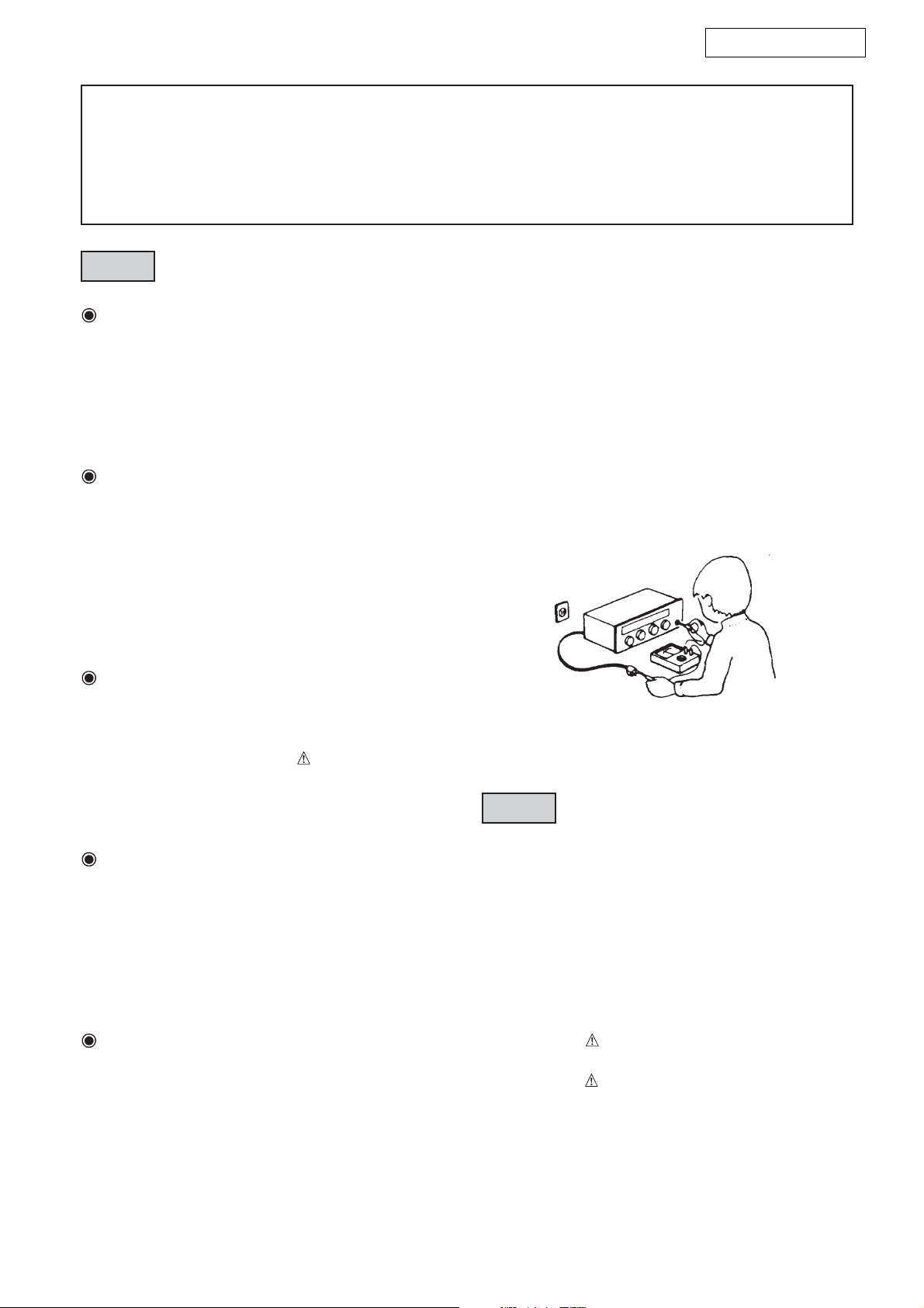
(絶縁チェックの方法)
電源コンセントから電源プラグを抜き、アンテナ
や、プラグなどを外し、電源スイッチを入れま
す。500V絶縁抵抗計を用いて、電源プラグのそれ
ぞれの端子と、外部露出金属部〔アンテナ端子、
ヘッドホン端子、マイク端子、入力端子など〕と
の間で、絶縁抵抗値が1MΩ以上であること、この
値以下のときは、セットの点検修理が必要です。
安全上重要な部品について
注 意
注 意
安全上重要な部品について
部品の取付けや配線の引きまわしは、元どおりに!
安全上、テープやチューブなどの絶縁材料を使用し
たり、プリント基板から浮かして取付けた部品があ
ります。また内部配線は引きまわしやクランパーに
よって発熱部品や高圧部品に接近しないように配慮
されていますので、これらは必ず元どおりにしてく
ださい。
サービス後は安全点検を!
サービスのために取り外したねじ、部品、配線など
が元どおりになっているか、またサービスした個所
の周辺を劣化させてしまったところがないかなどを
点検し、外部金属端子部と、電源プラグの刃の間の
絶縁チェックをおこなうなど、安全性が確保されて
いることを確認してください。
本機に使用している多くの電気部品、および機構部品
は安全上、特別な特性を持っています。この特性はほ
とんどの場合、外観では判別つきにくく、また、もと
の部品より高い定格(定格電力、耐圧)を持ったもの
を使用しても安全性が維持されるとは、限りません。
安全上の特性を持った部品は、このサービスマニュア
ルの配線図、部品表につぎのように表示していますの
で、必ず指定されている部品番号のものを使用願いま
す。
(1) 配線図…
(2) 部品表… マークで表示しています。
マークで表示しています。
指定された部品と異なるものを使用し
た場合には、感電、火災などの危険を
生じる恐れがあります。
2
Page 3
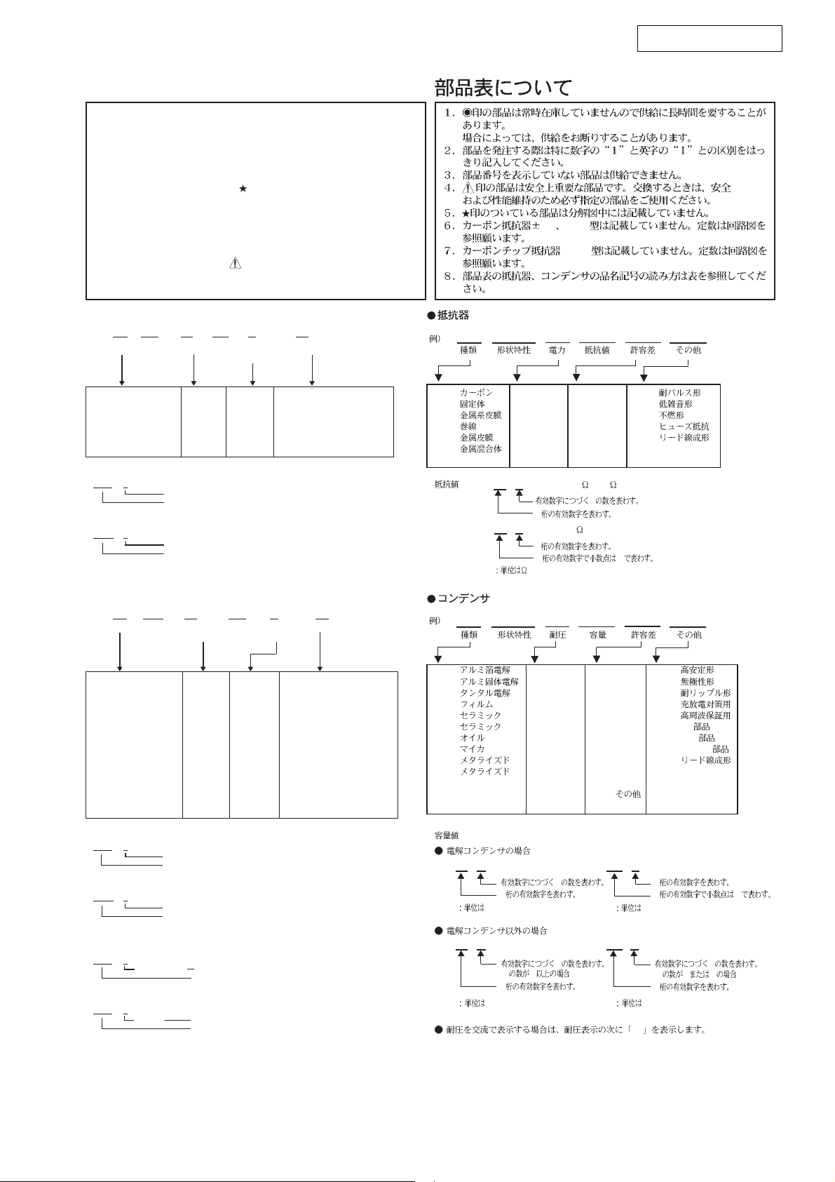
NOTE FOR PARTS LIST
l Part indicated with the mark "" are not always in stock and possibly to
take a long period of time for supplying, or in some case supplying of
part may be refused.
l When ordering of part, clearly indicate "1" and "I" (i) to avoid mis-
supplying.
l Ordering part without stating its part number can not be supplied.
l Part indicated with the mark "
l Not including Carbon Film Resister ±5%, 1/4W Type in the P.W.Board
parts list. (Refer to the Schematic Diagram for those parts.)
l Not including Carbon Chip Resister 1/16W Type in the P.W.Board parts
list. (Refer to the Schematic Diagram for those parts.)
WARNING:
Parts marked with this symbol
Use ONLY replacement parts recommended by the manufacturer.
ll
l
Resistors
ll
Ex.: RN 14K 2E 182 G FR
Type Shape Power Resist- Allowable Others
and per- ance error
formance
" is not illustrated in the exploded view.
have critical characteristics.
SC-M53 / SC-M73
5% 1/4W
1/16W
RN 14K 2E 182 G FR
RD : Carbon 2B : 1/8W F : ±1% P : Pulse-resistant type
RC : Composition 2E : 1/4W G : ±2% NL : Low noise type
RS : Metal oxide film 2H : 1/2W J : ±5% NB : Non-burning type
RW : Winding 3A : 1W K : ±10% FR : Fuse-resistor
RN : Metal film 3D : 2W M : ±20% F : Lead wire forming
RK : Metal mixture 3F : 3W
] Resistance
1 8 2 ⇒ 1800 ohm = 1.8 kohm
s
s
• Units: ohm
1 R 2 ⇒ 1.2 ohm
s
s
• Units: ohm
ll
l
Capacitors
ll
Ex.: CE 04W 1H 2R2 M BP
Type Shape Dielectric Capacity Allowable Others
3H : 5W
Indicates number of zeros after effective number.
2-digit effective number.
1-digit effective number.
2-digit effective number, decimal point indicated by R.
and per- strength error
formance
CE : Aluminum foil 0J : 6.3V F : ±1% HS : High stability type
electrolytic
CA : Aluminum solid 1A : 10V G : ±2% BP : Non-polar type
electrolytic
CS : Tantalum electrolytic 1C : 16V J : ±5% HR : Ripple-resistant type
CQ : Film 1E : 25V K : ±10% DL : For change and discharge
CK : Ceramic 1V : 35V M : ±20% HF : For assuring high
CC : Ceramic 1H : 50V Z : +80% U : UL part
CP : Oil 2A : 100V –20% C : CSA par t
CM : Mica 2B : 125V P : +100% W : UL-CSA type
CF : Metallized 2C : 160V –0% F : Lead wire forming
CH : Metallized 2D : 200V C : ±0.25pF
2E : 250V D : ±0.5pF
2H : 500V = : Others
2J : 630V
requency
RD : 2B : 1/8 W F : ±1% P :
RC : 2E : 1/4 W G : ±2% NL :
RS : 2H : 1/2 W J : ±5% NB :
RW : 3A : 1 W K : ±10% FR :
RN : 3D : 2 W M : ±20% F :
RK : 3F : 3 W
∗
CE 04W 1H 2R2 M BP
CE : 0J : 6.3 V F : ±1% HS :
CA : 1A : 10 V G : ±2% BP :
CS : 1C : 16 V J : ±5% HR :
CQ : 1E : 25 V K : ±10% DL :
CK : 1V : 35 V M : ±20% HF :
CC : 1H : 50 V Z : +80% U : UL
CP : 2A : 100 V −20% C : CSA
CM : 2B : 125 V P : +100% W : UL-CSA
CF : 2C : 160 V − 0% F :
CH : 2D : 200 V C : ±0.25pF
3H : 5 W
18 2
1R 2
Ö
2
Ö
1
2 R
2E : 250 V D : ±0.5pF
2H : 500 V = :
2J : 630 V
1800
1.2
=1.8k
0
] Capacity (electrolyte only)
2 2 2 ⇒ 2200μF
s
s
• Units: μF.
2 R 2 ⇒ 2.2μF
s
s
• Units: μF.
] Capacity (except electrolyte)
2 2 2 ⇒ 2200pF=0.0022μF
s
s
• Units: pF.
2 2 1 ⇒ 220pF
s
s
• Units: pF.
• When the dielectric strength is indicated in AC, "AC" is included after the dieelectric
strength value.
Indicates number of zeros after effective number.
2-digit effective number.
1-digit effective number.
2-digit effective number, decimal point indicated by R.
(More than 2) Indicates number of zeros after effective number.
(0 or 1) Indicates number of zeros after effective number.
2-digit effective number.
2-digit effective number.
∗
22 2
22 2
2200μF
Ö
2
μ
F
2200pF=0.0022μF
Ö
(0 2 )
2
p
F
0
0
2R 2
22 1
Ö
1
2 R
μ
F
Ö
(0 0 1 )
2
p
F
AC
2.2μF
220pF
0
3
Page 4

SC-M53 EXPLODED VIEW (EM/JP MODEL)
SC-M53 / SC-M73
12
9
16
7
1
WF (RED/WHT)
13
LEFT TERMINAL (TW)
5
3
9
6
2
TW (YEL/WHT)
14
4
15
(YEL/WHT)
RIGHT TERMINAL (WF)
(RED/WHT)
8
10
11
SC-M53 PARTS LIST OF EXPLODED VIEW (EM/JP MODEL)
※ 本表に記載されている部品は、補修用部品のため製品に使用している部品とは一部、形状、寸法などが異なる場合があります。
※ Thepartslistedbelowareformaintenanceonly,mightdifferfromthepartsusedintheunitinappearancesordimensions.
Note: The symbols in the column “Remarks” indicate the following destinations.
EM : U.S.A.,Canada,Europe & U.K. model
JP : Japan model
Ref. No. Part No. Part Name Remarks Q'ty New
1 00D 949 0052 300 SC-M53CWEM SERVICE AA110008-01 1 *
2 00D 949 0052 407 HOLDER 56-000-088-01 4 *
3 00D 949 0052 504 HOLDER 56-000-087-01 2 *
4 00D 949 0052 708 PACKING 29-100-140-01 1 *
5 00D 949 0052 902 PACKING 29-100-139-01 1 *
6 00D 949 0053 105 +P 4X20 TAPPING SCREW 70-018-420-04 4 *
7 00D 949 0053 406 PACKING 29-100-141-01 1 *
8 00D 949 0053 503 CR110025-01 SP UNIT CR110025-01W 1 *
9 00D 949 0053 707 +B 4X25 TAPPING SCREW 70-015-425-05 8 *
10 00D 949 0053 804 ORNAMENT ASSY 99-110-016-01 for EM model 1 *
10 00D 949 0055 802 ORNAMENT ASSY 99-110-016-11 for JP model 1 *
11 00D 949 0054 007 NET ASSY 99-110-025-01 1 *
12 00D 949 0054 201 SC-M53 N/W ASSY SET SERVICE AA000041-01 1 *
13 00D 949 0054 405 CORD ASSY 61-000-809-01 WF(RED/WHT) 1 *
14 00D 949 0054 502 CORD ASSY 61-000-809-11 TW(YEL/WHT) 1 *
15 00D 949 0054 803 SOUND ABSORBENT 54-000-150-01 1 *
16 00D 949 0054 900 RATING LABEL 60-002-180-01 for EM model 1 *
16 00D 949 0055 909 RATING LABEL 60-002-197-01 for JP model 1 *
4
Page 5

SC-M73 EXPLODED VIEW (EM MODEL)
SC-M53 / SC-M73
11
15
16
10
12
9
18
7
1
16
15
WF (RED/WHT)
13
LEFT TERMINAL (TW)
(YEL/WHT)
2
RIGHT TERMINAL (WF)
8
(RED/WHT)
9
3
17
4
14
TW (YEL/WHT)
5
6
SC-M73 PARTS LIST OF EXPLODED VIEW (EM MODEL)
※ 本表に記載されている部品は、補修用部品のため製品に使用している部品とは一部、形状、寸法などが異なる場合があります。
※ Thepartslistedbelowareformaintenanceonly,mightdifferfromthepartsusedintheunitinappearancesordimensions.
Ref. No. Part No. Part Name Remarks Q'ty New
1 00D 949 0052 203 SC-M73CWEM SERVICE AA120010-01 1 *
2 00D 949 0052 601 PACKING 29-100-138-01 1 *
3 00D 949 0052 805 PACKING 29-100-137-01 1 *
4 00D 949 0053 008 FOOT 90-000-110-01 4 *
5 00D 949 0053 202 +K 4X18 TAPPING SCREW 70-027-418-04 4 *
6 00D 949 0053 309 RUBBER FOOT 56-000-072-01 4 *
7 00D 949 0053 406 PACKING 29-100-141-01 1 *
8 00D 949 0053 600 XS025022-01 SP UNIT XS025022-01W 1 *
9 00D 949 0053 707 +B 4X25 TAPPING SCREW 70-015-425-05 10 *
10 00D 949 0053 901 RING ASSY 99-120-037-01 1 *
11 00D 949 0054 104 NET ASSY 99-120-036-01 1 *
12 00D 949 0054 308 SC-M73 N/W ASSY SET SERVICE AA000039-01 1 *
13 00D 949 0054 405 CORD ASSY 61-000-809-01 WF(RED/WHT) 1 *
14 00D 949 0054 502 CORD ASSY 61-000-809-11 TW(YEL/WHT) 1 *
15 00D 949 0054 609 PLAIN WASHER 69-034-400-01 1 *
16 00D 949 0054 706 HEXAGON NUTS 71-005-400-06 1 *
17 00D 949 0054 803 SOUND ABSORBENT 54-000-150-01 1 *
18 00D 949 0055 006 RATING LABEL 60-002-181-01 1 *
5
Page 6

SC-M53 PACKING VIEW (EM/JP MODEL)
7
12
SC-M53 / SC-M73
13
10
3
6
4
5
EM model
14
13 19
11
JP model
18
16
15
16
9
8
17
2
1
SC-M53 PARTS LIST OF PACKING & ACCESSORIES (EM/JP MODEL)
※ 本表に記載されている部品は、補修用部品のため製品に使用している部品とは一部、形状、寸法などが異なる場合があります。
※ Thepartslistedbelowareformaintenanceonly,mightdifferfromthepartsusedintheunitinappearancesordimensions.
Note: The symbols in the column “Remarks” indicate the following destinations.
EM : U.S.A.,Canada,Europe & U.K. model JP : Japan model
Ref. No. Part No. Part Name Remarks Q'ty New
1 00D 949 0051 204 MIRROR MAT SHEET 85-000-598-01 2 *
2 00D 949 0051 107 POLY BAG 85-000-573-81 2 *
3 00D 949 0051 408 SUPPLIED CORD SET 62-000-464-01 2 *
4 - POLY BAG 85-000-568-21 1 *
5 00D 949 0050 603 FOAM PLUG 54-000-104-21 2 *
6 - POLY BAG 85-000-568-31 1 *
7 00D 949 0050 700 ANTI-SLIP PAD 65-000-259-01 1 *
8 00D 949 0051 301 OPERATING INSTRUCTIONS 87-001-219-01 for EM model 1 *
8 00D 949 0056 209 OPERATING INSTRUCTIONS 87-001-224-01 for JP model 1 *
9 - DENON SERVICE NETWORK 87-001-187-01 1
9 00D 515 0918 403 DENON SERVICE NETWORK 87-000-822-11 for JP model 1
10 00D 949 0050 807 CUSHION (TOP) 80-000-634-01 1 *
11 00D 949 0050 904 CUSHION (BOTTOM) 80-000-634-11 1 *
12 00D 949 0055 501 PARTITION 81-001-283-01 1 *
13 00D 949 0051 000 INDIVIDUAL CARTON 83-000-528-01 for EM model 1 *
13 00D 949 0056 005 INDIVIDUAL CARTON 83-000-536-01 for JP model 1 *
14 00D 949 0055 705 COLOR LABEL 89-000-720-01 2 *
15 00D 949 0055 103 CONTROL CARD 87-001-221-01 2 *
16 00D 949 0055 200 POS LABEL 89-000-715-01 for EM model 2 *
16 00D 949 0056 102 POS LABEL 89-000-722-01 for JP model 1 *
17
18
19
00D 949 0056 306 SERIAL NO. LABEL 89-000-136-01 for JP model 1 *
00D 515 0919 208 WARRANTY CARD 87-000-821-01 for JP model 1
- POLY BAG 85-000-568-41 1 *
6
Page 7

SC-M73 PACKING VIEW (EM MODEL)
11
SC-M53 / SC-M73
16
8
7
2
1
3
6
4
5
9
15
10
12
13
14
SC-M73 PARTS LIST OF PACKING & ACCESSORIES (EM MODEL)
※ 本表に記載されている部品は、補修用部品のため製品に使用している部品とは一部、形状、寸法などが異なる場合があります。
※ Thepartslistedbelowareformaintenanceonly,mightdifferfromthepartsusedintheunitinappearancesordimensions.
Ref. No. Part No. Part Name Remarks Q'ty New
1 00D 949 0052 009 MIRROR MAT SHEET 85-000-599-01 2 *
2 00D 949 0051 903 POLY BAG 85-000-573-91 2 *
3 00D 949 0051 505 SUPPLIED CORD SET 62-000-465-01 2 *
4 - POLY BAG 85-000-568-21 1 *
5 00D 949 0050 603 FORM PLUG 54-000-104-21 2 *
6 - POLY BAG 85-000-568-31 1 *
7 00D 949 0052 106 OPERATING INSTRUCTIONS 87-001-220-01 1 *
8 - DENON SERVICE NETWORK 87-001-187-01 1
9 00D 949 0051 602 CUSHION (TOP) 80-000-633-01 1 *
10 00D 949 0051 709 CUSHION (BOTTOM) 80-000-633-11 1 *
11 00D 949 0055 608 PARTITION 81-001-283-11 1 *
12 00D 949 0051 806 INDIVIDUAL CARTON 83-000-529-01 1 *
13 00D 949 0055 705 COLOR LABEL 89-000-720-01 2 *
14 00D 949 0055 307 CONTROL CARD 87-001-221-11 2 *
15 00D 949 0055 404 POS LABEL 89-000-716-01 2 *
16 - POLY BAG 85-000-568-41 1 *
7
 Loading...