

Denon DVM-715, DVM-1815, DVM-2815 Service Bulletin

100 Corporate Drive Mahwah, NJ 07430
Service Bulletin
No. : OST-F1047
Date:
March 15, 2007
_____________________________________________________________
Model: DVM-715, DVM-1815, DVM-2815
Subject: Countermeasure for the malfunction of the FG Sensor.
Symptom: The unit does not play a disc, and the spindle motor generates an
unusual noise. The malfunction occurs due to faulty bonding of the FG Sensor
wire
Solution:
MECHA HOLDER ASS'Y.
Replace the FG CBA that is attached under the Turntable of the
MODIFICATION
one (see the Parts section for details). To remove the Mechanism from the unit,
please refer to pages 10 and 11 in the Service Manual.
: Replace the FG CBA (P. W. Board) with the following new
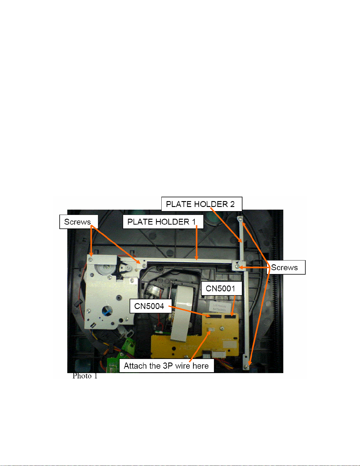
* Modification Procedures: 1) Attach the 3P-Wire JIGU to the CN5006 on the
rear of the MECHA HOLDER ASS'Y to short circuit the Optical Pick-up terminals.
(Refer to the Photo #1)
2) Disconnect the FFC cables from the CN5001 (14P) and CN5004 (20P)
connectors. (Refer to the Photo #1)
3) Remove five screws on the PLATE HOLDER 1 and PLATE HOLDER 2. (Refer
to the Photo #1)
4) Disconnect the FFC cable from the CN5002 connector. (Refer to the Photo #2)
5) Rotate the Gear clockwise and move the MECHA HOLDER to the upside.
(Refer to the Photo #2)
______________________________________________________________________________________
The information contained in this document is intended for the exclusive use by DENON Authorized Service Centers and their
employees. This document may contain information that is privileged, confidential and may be protected from disclosure under
applicable laws and terms of the DENON Service Agreement. Any distribution, disclosure, dissemination or copying of this
document and the information it contains is prohibited. No responsibility will be accepted by DENON for any damage, injury or loss
resulting from the misuse of the information contained in this document.
CONFIDENTIALITY NOTICE:
6) While pulling the MECHA HOLDER toward you, detach the MECHA HOLDER.
(Refer to the Photo #3)
7) Remove one piece of FG CBA fixing screw and take out the FG CBA from the
MECHA HOLDER ASS'Y.
8) Three wires Yellow, Blue and White colors have been soldered on the FG
CBA. Use soldering Iron to detach the wires from the FG CBA, and replace the
FG CBA with new one. (Refer to the Photo #4) Then, assemble the FG CBA in
reverse order of the disassembling procedures (from #1 to #8).
9) Pull out the 3P-Wire JIGU from the CN5006 on the rear of the MECHA
HOLDER ASS'Y.
Note: When attaching three wires on the new FG CBA, be sure to solder the wire
to where the capital letter of the color has been printed on the rear side of the P.
W. Board respectively.
______________________________________________________________________________________
CONFIDENTIALITY NOTICE:
The information contained in this document is intended for the exclusive use by DENON Authorized Service Centers and their
employees. This document may contain information that is privileged, confidential and may be protected from disclosure under
applicable laws and terms of the DENON Service Agreement. Any distribution, disclosure, dissemination or copying of this
document and the information it contains is prohibited. No responsibility will be accepted by DENON for any damage, injury or loss
resulting from the misuse of the information contained in this document.
 Loading...