

Denon DVM-4800 Service Manual
SERVICE MANUAL
For U.S.A. & Canada model
Digital Player
MODEL
DVD VIDEO AUTO CHANGER
DVM-4800
Some illustrations using in this service manual are slightly different from the actual set.
14-14, AKASAKA 4-CHOME, MINATO-KU, TOKYO 107-8011 JAPAN
Telephone: 03 (3584) 8111
X0124 205 NC 0110

DVM-4800
SPECIFICATIONS
Signal system: NTSC
Applicable discs: (1) DVD-video/audio discs
1-layer 12 cm single-sided discs, 2-layer 12 cm single-sided discs,
2-layer 12 cm double-sided discs (1 layer per side)
1-layer 8 cm single-sided discs, 2-layer 8 cm single-sided discs,
2-layer 8 cm double-sided discs (1 layer per side)
(2) Compact discs (CD-DA, Video CD)
12 cm discs, 8 cm discs
S-Video output: Y output level: 1 Vp-p (75 Ω/ohms) C output level: 0.286 Vp-p
Output connectors: S connectors, two sets
Video output: Output level: 1 Vp-p (75 W/ohms) Output connector: Pin-plug jacks, two sets
Component output: Y output level: 1 Vp-p (75 Ω/ohms)
C
B/CR output level: 0.650 Vp-p (75 Ω/ohms) PB/PR output level: 0.700 Vp-p (75 Ω/ohms)
Output connector: Pin jack, 1 set
Audio output: Fixed output level: 2 Vrms (1 kHz, 0 dB)
Number of connectors: 1 set (2 ch mixed output)
1 set (6 ch discrete output)
Audio output properties: (1) Frequency response
• DVDs (linear PCM) : 2 Hz to 22 kHz (48 kHz sampling)
: 2 Hz to 44 kHz (96 kHz sampling)
: 2 Hz to 88 kHz (192 kHz sampling)
• CDs : 2 Hz to 20 kHz
(2) S/N ratio
• DVDs : 115 dB
• CDs : 115 dB
(3) Total harmonic distortion
• DVDs : 0.0025 %
• CDs : 0.0030 %
(4) Dynamic range
• DVDs : 108 dB
• CDs : 100 dB
Digital audio output: Optical digital output: Optical connector, 1 set
Coaxial digital output: Pin jack, 1 set
Power supply: AC 120 V, 60 Hz
Power consumption: 22 W
Maximum external
dimensions: 434 (width) x 131 (height) x 415 (depth) mm (not including protruding parts)
Mass: 7.2 kg
■ Remote Control Unit: RC-548
Type: Infrared pulse
Power Supply: DC 3 V, two batteries ("AAA" (R03))
2
DVM-4800
3
DVM-4800
1. COUNTERMEASURES AGAINST ELECTROSTATIC DISCHARGE (ESD)
The laser diode in the traverse unit (laser pickup) may be damaged by static electricity charged in your cloth or body. Be
careful not to damage it by ESD when handling for servicing.
1.1 Grounding for Electrostatic Breakdown Prevention
Components using an optical pickup (laser diode) such as DVD players etc. are liable to breakdown by static electricity under
the working environment.
Perform repair work in the working condition having proper grounding for preventing static electricity.
1.1.1 Work table grounding
Put a conductive material (sheet) or steel sheet on the area where the optical pickup is placed and ground the sheet.
1.1.2 Human body grounding
Use an anti-static wrist strap to discharge the static electricity from your body.
1.1.3 Handling of optical pickup
1) The optical pickup for spare parts is supplied with its laser diode shorted to ensure quality during transportation.
After the parts replacement, return to normal by proper procedures. (refer to the pages related)
2) Do not use a tester or etc. for checking the laser diode since the laser diode may be damaged easily by the voltage
of the tester inside battery.
Wrist strap
(Anti-static bracelet)
Iron plate or some metals
to conduct electricity
1.2 Handling of Traverse Unit (laser pickup)
1.2.1 Do not apply a strong shock to the traverse unit (laser pickup) since it is made of precise structure.
1.2.2 To prevent the breakdown of the laser diode, install the flexible cable after removing the short pin for preventing a
electrical charge. When removing or connecting the short pin, finish the job in as short time as possible.
Also, cut out the short land of the flexible cable using nippers and etc. after replacing the optical pickup. Refer to
TRAVERSE UNIT DISASSEMBLY” in this manual for the handling of the traverse unit.
1.2.3 Be careful not to apply excessive stress to the flexible board (FPC Board) since it may cause cutting.
1.2.4 Do not turn the variable resistor of the laser power since it is not adjustable.
4
DVM-4800
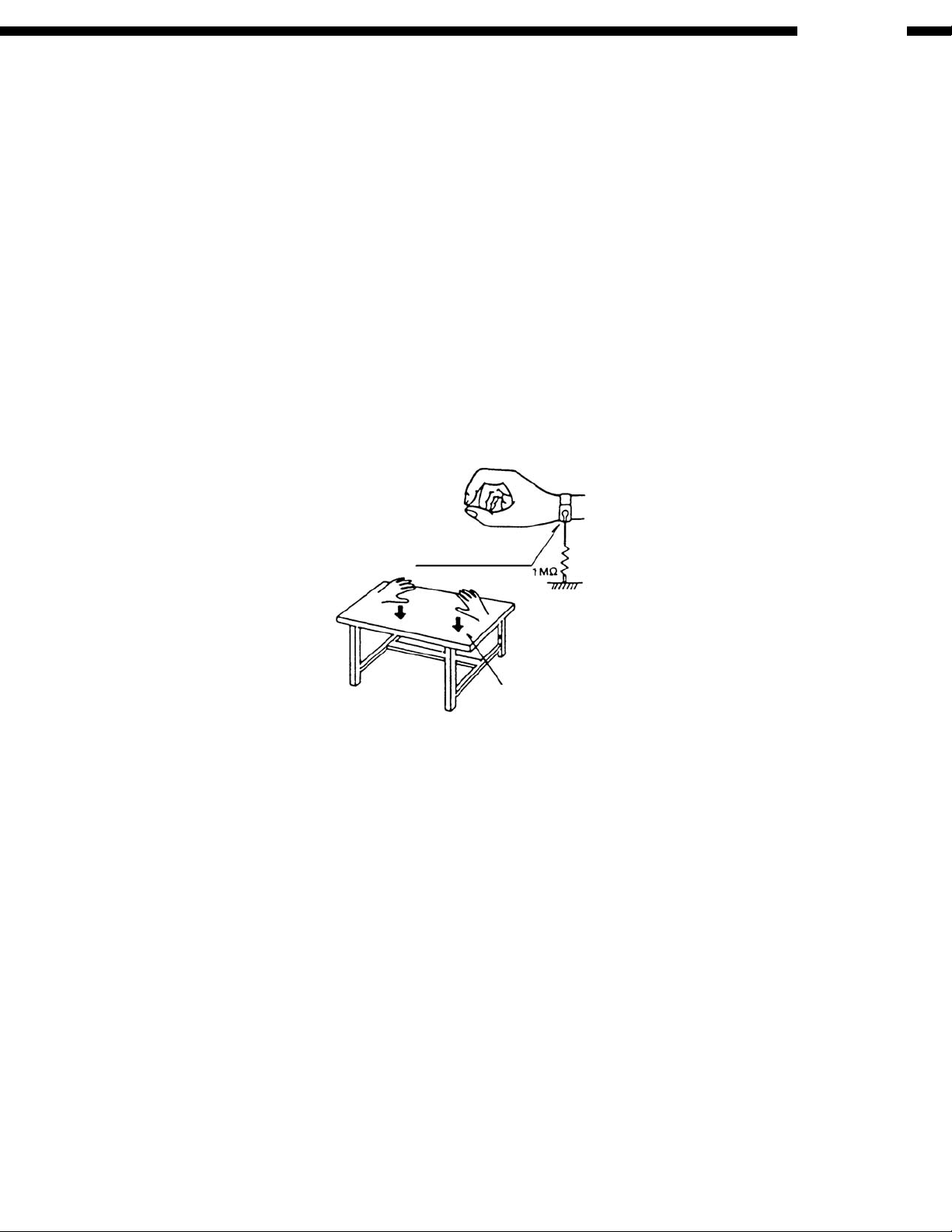
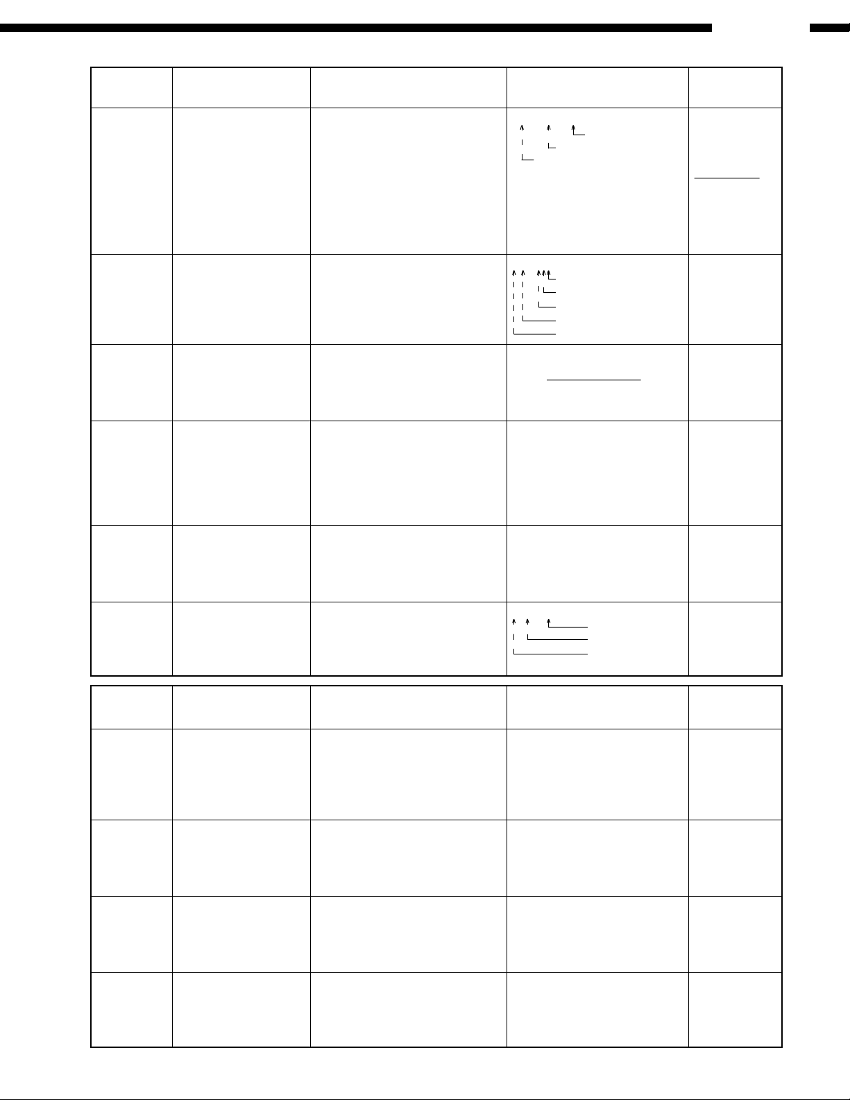
2. OPTICAL PICKUP SELF-DIAGNOSIS AND REPLACEMENT PROCEDURE
2.1 Self-diagnosis
The optical pickup self-diagnosis function and tilt adjustment check function have been included in this unit. When repairing,
use the following procedure for effective Self-diagnosis and tilt adjustment. Be sure to use the self-diagnosis function before
replacing the optical pickup when "NO DISC" is displayed. As a guideline, you should replace the optical pickup when the
value of the laser drive current is more than 55.
Note:
Press the power button to turn on the power, and check the value within three minutes before the unit warms up.
(Otherwise, the result will be incorrect.)
"NO DISC" is displayed, unit does
not play smoothly, etc.
Use the optical pickup self-diagnosis function.
Method: With no disc in the player:
• Press the "DISPLAY" button on the
remote control unit while pressing the
Check the laser drive current.
"PAUSE" and "OPEN/CLOSE" buttons on
the player.
[Display content]
Value is 70 (DVD),
55 (CD) or less
Replace the optical pickup (Refer
to the section "OPTICAL PICKUP
REPLACEMENT PROCEDURE"
in this Guide.)
Check the laser drive current after
replacement.
Write the present value into the
unit if it is 60 (DVD), 45 (CD) or
less.
Do the optical pickup tilt adjustment. (Refer to the section "TILT
ADJUSTMENT" in this Guide.)
Value is more than
70 (DVD), 55 (CD)
Use the tilt
adjustment check
function.
Factory setting Present value
Replace with a new optical pickup if the present
value is more than 60 (DVD), 45 (CD).
Cause: Damage due to static electricity during
replacement.
Method: With no disc in the player:
• Press the "DISPLAY" button on the remote
control unit while pressing the "PAUSE" and
"OPEN/CLOSE" buttons on the player.
Write the present value
into the player if it is 45
or less.
Writing Method:
• Press the "PAUSE" button on the remote
control unit while pressing the "PAUSE" and
"OPEN/CLOSE" buttons on the player.
Initialize the player.
5

2.2 Cautions to Be Used Before Replacing the Optical Pickup Unit
and Spindle Motor Assembly
Before replacing the optical pickup unit and spindle motor assembly, check the total using hours for each of them.
The checking method is as follow:
Operating state & Key operation Display
Using hours of CD laser Press "PAUSE, FWD-SKIP" and "5" on the T1_xxxx_yyyy: total hours are
remote control in this order while the unit displayed by 4-digit figures (unit: 10 hours).
is stopped yyyy: CD laser Time
Using hours of DVD laser Press "PAUSE, FWD-SKIP" and "5" on the T1_xxxx_yyyy: total hours are
remote control in this order while the unit displayed by 4-digit figures (unit: 10 hours).
is stopped xxxx: DVD laser Time
Using hours of SP motor Press "PAUSE, FWD-SKIP" and "6" on the T2_xxxx: total hours are
remote control in this order while the unit displayed by 4-digit figures
is stopped (unit: 10 hours).
Resetting using hours While displaying Timer 1 data, press STOP T1_0000_0000
of CD and DVD lasers and FWD-SKIP buttons on the player, and
(Simultaneous resetting) "5" button on the remote control unit
Resetting using hours While displaying Timer 2 data, press STOP T2_0000
of the motor and FWD-SKIP buttons on the player, and
"6" button on the remote control unit
DVM-4800
Cautions to be taken when replacing the optical pickup
The optical pickup may break down due to the static electricity of human body. Take proper protection measures against static
electricity before repairing the parts around the optical pickup. (See the page describing the PREVENTION OF STATIC
ELECTRICITY DISCHARGE.)
1. Do not touch the areas around the laser diode and actuator.
2. Do not judge the laser diode with a tester. (The tester will be damaged easily.)
3. It is recommended to use a destaticized soldering iron for short-circuiting or removing the laser diode.
(Recommended soldering iron) HAKKO ESD Product.
4. Solder the land of the flexible cable in the optical pickup.
Note:
• When using a soldering iron which is not destaticized, short-circuit the terminal face of the flexible case with a clip.
After that, short-circuit the land.
• After the repairing work is completed, remove the solder according to the correct procedure shown in this Technical
Guide.
Optical pickup unit
Flexible cable
Ground with a clip.
6

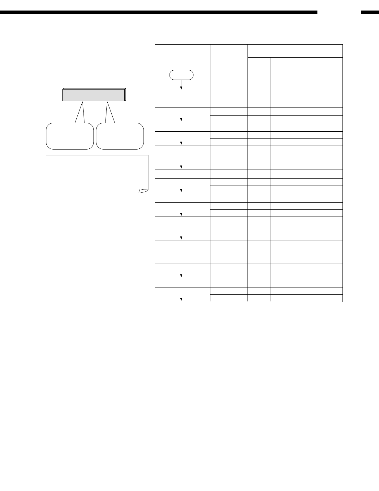
3. SELF-DIAGNOSIS FUNCTION AND SERVICE MODES
3.1 Self-diagnosis Function and Service Modes
Improving the self-diagnosis function
The self-diagnosis function in our DVD player currently in use is improved as follows:
DVM-4800
Our DVD player currently
in use
UHF error display
The latest error storage
function
n=1
Jitter/read error display
Laser drive current display
For DVD
Our new DVD
UHF error display
The latest error storage
n=20
Jitter/read error display
Focus drive value display
laser drive current display
For DVD/CD
ADSC internal RAM data
display
Servo process display
Total operation time
display SP motor
Laser (DVD/CD)
The storage capacity is increased.
The focus drive current value can be displayed.
The servo learning value stored in the RAM data
inside the ADSC (servo controller) IC is displayed.
Mainly in the initial starting operation period of the
player, a number is allotted to the servo process
of each step, and the process of the starting
operation can be displayed.
The operation times of SP motor and the laser
(both for the DVD and CD) can be displayed.
7

3.2 Service mode table
Pressing various button combinations on the player and remote control unit can activate the service modes.
DVM-4800
Item
Jitter check In PLAY mode, press Jitter check J_xxx_yyy_zz Press STOP
Error code In ** mode, press PAUSE Error code check Error code (play_err) is expressed Cancelled
check and OPEN buttons on the The latest error code stored in in the following convention. automatically
Initial setting In STOP mode, press Initial setting of laser drive current LDO_034_028 Cancelled
of laser drive PAUSE and OPEN buttons lnitial current value for each of DVD
current on the player, and PAUSE laser and CD laser is separately
DVD laser In STOP mode, press DVD laser drive current measurement LDD_034_032 Cancelled
drive current PAUSE and OPEN buttons DVD laser drive current is measured Measured current automatically
measurement on the player, and and the result is displayed together
ADSC internal In ** mode, press PAUSE ADSC internal RAM data check A_DFA_6901 Press STOP
RAM data and OPEN buttons on the ADSC internal RAM data is read out
check player, and RETURN and displayed. Address
Servo process In STOP mode, press Servo process display Turn off the
display PAUSE and FWD-SKIP The servo process from STOP to primary power.
button combination method
PAUSE and OPEN buttons Jitter rate is measured and displayed. Focus drive value or OPEN button.
on the player, and "5" Measurement is repeatedly done in Read error counter
button on the remote the cycle of one second. Read error Jitter rate
control unit. counter starts from zero upon mode Jitter check mode
setting, When target block data failed
to be read out, the counter advances Jitter rate is shown in decimal
by one increment. When the failure is notation to one place of decimal.
caused by minor error, it may be Focus drive value is shown in
corrected when retried to enable hexadecimal notation.
successful reading. In this case, the
counter advances by one. When the
error persists even after retry, the
counter may jump by two or more.
player, and "0" button on EEPROM is displayed.
the remote control unit.
* With pointing of cursor
up and down on diaplay,
panel controller switches * "nn" denotes the serial number
the serial number of of history.
history and sends out the
command accordingly.
button on the remote saved in EEPROM.
control unit.
DISPLAY button on the with the initial value stored in
remote control unit. EEPROM.
After the measurement, DVD laser The value denotes the current in
emission is kept on. It is turned off decimal notation. The above
when POWER key is switched off. (It example shows the initial current
is also turned off when the primary is 34mA and the measured value
power is switched off.) is 32mA.
button on the remote Change the address with CLEAR key
control unit. operation to show the data for 11
addresses. The value is shown in hexadecimal
buttons on the player, and ACCESS is displayed.
"7" button on the remote
control unit.
Function Display
Error code=0 x DAXX is expressed: ➔ nn UXX
Error code=0 x DBXX is expressed: ➔ nn HXX
Error code=0 x DXXX is expressed: ➔ nn FXX
Error code=0 x 0000 is expressed: ➔ nn F--
DVD laser current measurement
Laser current measurement mode
The value denotes the current in
decimal notation. The above
example shows the initial current
is 34mA and 28mA for DVD laser
and CD laser respectively when
the laser is switched on.
Initial current stored in EEPROM
DVD laser current measurement mode
ADSC internal RAM data check mode
notation. The above example
shows the data in ADSC address
DFAh is 6901h.
CD laser current measurement
RAM data for specified address
Player mode and
Cancellation
5 seconds later.
automatically
5 seconds later.
5 seconds later.
or OPEN button.
8
DVM-4800
Item
CD laser drive In STOP mode, press CD laser drive current measurement LDC_028_026
current PAUSE and FWD-SKIP CD laser drive current is measured
measurement buttons on the player, and and the result is displayed together
Version In STOP mode, press Version display srrr_xyzzz Cancelled
display PAUSE and OPEN buttons
Lighting of In ** mode, press Lighting of display tube Press STOP
display tube PAUSE and OPEN buttons or OPEN button.
Dealer's lock In STOP mode, press Dealer's lock "LOCKED" sign appears when Repeat the
Initializaition In STOP mode, press Initialization "INITIALIZED"
Region display In STOP mode, press Region display x_yy_zzz Cancelled
button combination method
DISPLAY button on the with the initial value stored in
remote control unit. EEPROM.
After the measurement, CD laser The value denotes the current in
emission is kept on. It is turned off decimal notation
when POWER key is switched off. (It The above example shows the
is also turned off when the primary initial current is 28mA and the
power is switched off.) measured value is 26mA.
on the player, and "7"
button on the remote
control unit.
on the player, and "9"
button on the remote
control unit.
STOP button on the The lock is switched ON or OFF. dealer's lock is switched on, or same operation.
player, and POWER button When dealer's lock is ON, it prohibits when secondary power key or tray
on the remote control unit. switching off of the secondary power opening key is pressed while the
and tray opening. lock is on.
When the lock is switched, its ON/OFF "UNLOCKED" sign appears when
status is stored in EEPROM. dealer's lock is switched off.
PAUSE, BWD-SKIP and User settings are cancelled and player
OPEN buttons on the is initialized to factory setting.
player for 3 seconds or
longer.
PAUSE and OPEN buttons N: NTSC/6: PAL60 automatically
on the player, and "6" N: noPAL/P: PAL 5 seconds later.
button on the remote Region No.
control unit.
Function Display
Measured current
Initial current stored in EEPROM
CD laser current measurement mode
System controller release number
System controller model number
System controller generation
Panel controller release number
Panel controller model number
Player mode and
Cancellation
automatically
5 seconds later.
Item
Timer 1 check In STOP mode, press Timer 1 check T1_1234_5678 Cancelled
Timer 1 reset While displaying Timer 1 Timer 1 reset T1_0000_0000 Cancelled
Timer 2 check In STOP mode, press Timer 2 check T2_1234 Cancelled
Timer 2 reset While displaying Timer 2 Timer 2 reset T2_0000 Cancelled
button combination method
PAUSE and FWD-SKIP Laser operation timer Operation time is
buttons on the player, and measured separately for DVD laser and to the right CD laser time. 5 seconds later.
"5" button on the remote and CD laser.
control unit. notation in a unit of 10 hours.
data, press STOP and Laser operation timer Operation time automatically
FWD-SKIP buttons on the of both DVD laser and CD laser is 5 seconds later.
player, and "5" button on reset all at once.
the remote control unit.
PAUSE and FWD-SKIP Spindle motor operation timer
buttons on the player, and
"6" button on the remote notation in a unit of 10 hours.
control unit. "0000" will follow "9999".
data, press STOP and Spindle motor operation timer automatically
FWD-SKIP buttons on the 5 seconds later.
player, and "6" button on
the remote control unit.
Function Display
Shown to the left is DVD laser time,
Time is shown in 4 digits of decimal
"0000" will follow "9999".
Time is shown in 4 digits of decimal
Player mode and
Cancellation
automatically
automatically
5 seconds later.
9
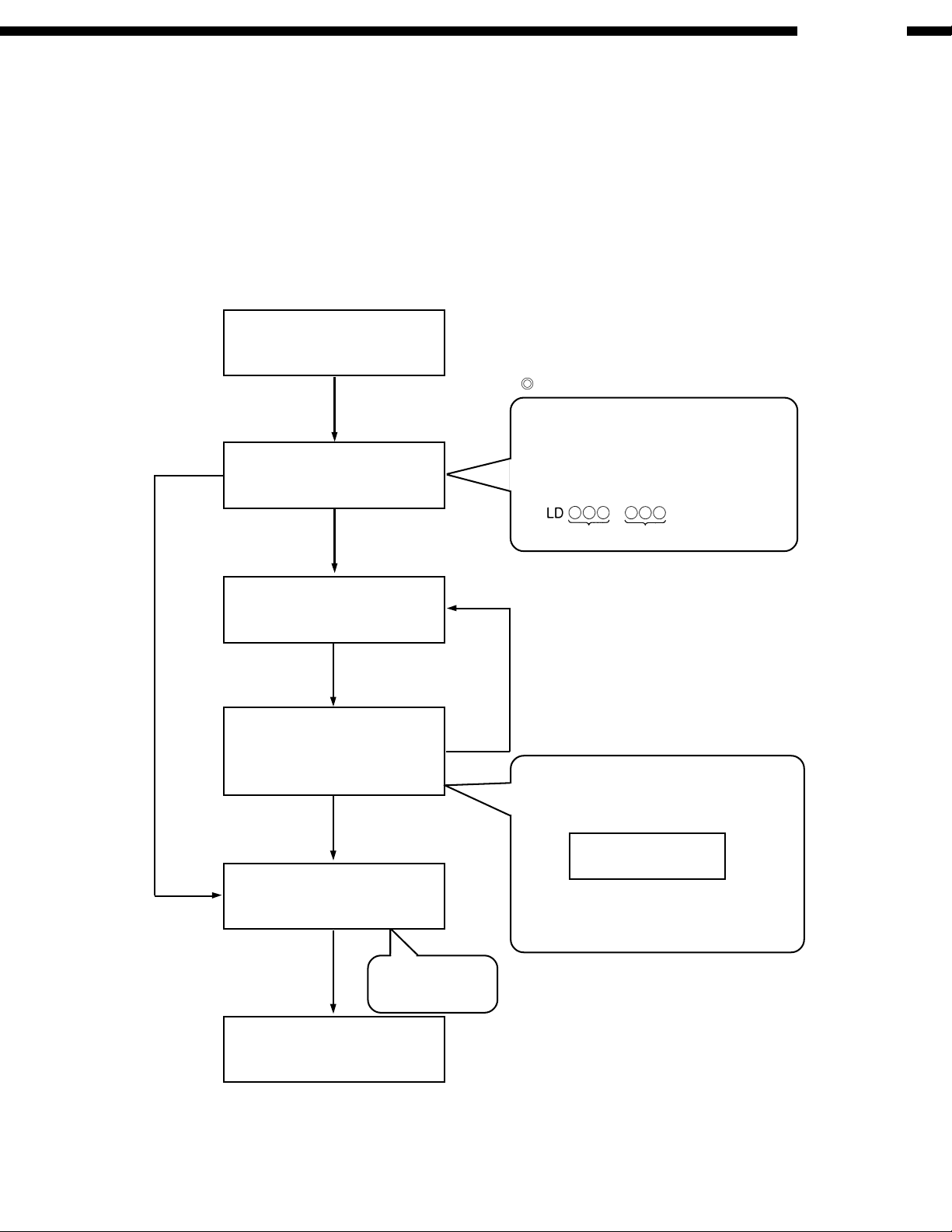
3.3 Servo Process Flow
DVM-4800
Specification of the servo process
display in the starting flow
1 2 0 9
Servo process
that has stopped
(Restrictions)
All processes that are under operation
cannot be displayed due to the limit of
the processing time.
Servo process
that is under
operation
Starting flow
START
Initial setting
Tray control
TRV initial movement
Disc detection
Disc type distinction
Focus servo
Tracking servo
Range of the
servo process
numbers
00 00 Each initial setting
01 01 TRV initial movement
02~08 02 Initial setting in FE system
02~08 02 Initial setting in FE system
10~13 12 Focus ON
14~15 15 Tracking ON
Processing items
Contents of each processNumber
05 Detecting LD ON HALF
08 Detecting CD LD ON
13 FBAL adjustment
Gain learning
ID read
17 17 Gain adjustment in ADSC
focus system
18~1A 19 DBAL/equalizer adjustment
1A ID read
10

DVM-4800
3.4 Servo Process Display Mode
In starting operation of the player, a number is allotted to each servo process so that the operation of each step can be seen.
The relation between the process and the displayed number are as follows:
Number allotment to the servo process
Process classification Each processing item Description Process number
Initial start process Initial start The process starts after the tray is loaded. (The state 0~40
is changed to "READY" or "PREPARE".)
Secondary learning Servos for the DVD-DL 1st layer and the CD-DA double 50~7F
Restart process Restart When a user operates in the "READY" state, each servo 80~9F
Seek process Seek The optical pickup is moved to the disc destination in A0~BF
Repair process Recover
(Error check) An error is searched in the PLAY/SEEK state. C1~C3
(Attention) An error is recovered following the attention error C4~C6
(Q code read) If any Q code is improperly read, reset and retry. C7~C9
Stop process Stop A servo is controlled in response to the user's operation F0~FF
speed are learned in this step.
is turned on.
this process.
interrupt from the S-ODC.
to stop the disc completely.
3.5 ADSC Internal Ram Data Display
The servo learning value in the RAM data inside the servo processor ADSC is displayed.
The value is useful for the servo operation/disc quality judge including the OPU.
The concrete contents are shown below:
Address
Contents of display
4B4 Focus gain learning value for DVD-S, DVD-D(L0), CD, and VCD
4BC Focus gain learning value for DVD-D(L1)
4B6 Focus balance learning value for DVD-S, DVD-D(L0), CD, and VCD
4BE Focus balance learning value for DVD-D(L1)
4B5 Tracking gain value for DVD-S, DVD-D(L0), CD, and VCD
4BD Tracking gain value for DVD-D(L1)
TB0 Tracking balance value for DVD-S, DVD-D(L0), CD, and VCD
TB1 Tracking balance value for DVD-D(L1)
DBD DSL offset learning value for DVD-S and DVD-D
DBC DSL offset learning value for CD and VCD
FC0 Equalizer FC value for DVD-S, DVD-D(L0), CD, and VCD
BT0 Equalizer BOOST value for DVD-S, DVD-D(L0), CD, and VCD
FC1 Equalizer FC value for DVD-D(L1)
BT1 Equalizer BOOST value for DVD-D(L1)
11

DVM-4800
3.6 Sales demonstration lock function
This function prevents discs from being lost when the unit is used for sales demonstrations by disabling the disc eject
function. "LOCKED" is displayed on the unit, and ordinary operation is disabled.
Setting
The sales demonstration lock is set by simultaneously pressing STOP button on the player and POWER button on the
remote control unit.
Cancellation
The lock can be cancelled by the same procedure as used in setting. ("UNLOCKED" is displayed on cancellation.
Disconnecting the power cable from power outlet does not cancel the lock.)
3.7 Service Precautions
3.7.1 Recovery after the DVD player is repaired
When an FROM or an EEPROM in and on the module P.C.B. has replaced, carry out the recovery disc processing to
optimize the drive.
Playback the disc above to process the recovery automatically.
Recovery disc (Product number: RFKZD5TR001)
Note:
This unit requires no initialization process carried out after the traditional DVD players were repaired.
When the recovery measures are taken, the customer setting will return to the factory setting as same as the procedure
described in item of "Initialization" in 2.2 is carried out. Write down the contents of the setting before recovery processing,
and reset the player.
3.7.2 Firmware version-up of the DVD player
The firmware of the DVD player may be renewed to improve the quality including operationability and playerbility to the
substandard discs processing to optimize the drive.
The version-up disc has also a recovery function so that you don't need use the recovery disc again.
Note:
If the AC power supply is shut out during version-up due to a power failure, the version-up is improperly carried out.
In such a case, replace the FROM and carry out the version-up again.
The product number of the version-up disc will be noticed when it is supplied.
3.7.3 Initialization of DVD Player
Initialize the DVD player when replacing CPU and its peripheral parts, and Mother P.W.B., etc.
How to Initialize
Pressing the "STILL/PAUSE" + "SKIP REW" + "OPEN/CLOSE" buttons at once makes DVD player initialization (factory
setting condition). "INITIALIZED" is indicated on the screen and "INITIALIZE" on the display of the main unit.
Note
When the initialization has been made, the contents of user setting is lost.
Therefore, memorize the contents of user setting prior to the initialization and re-set them again after the initialization.
3.7.4 Setting after Repair
After finishing the repair work, follow the steps below.
Setting Condition
At the power on state,
1) Press the "OPEN/CLOSE" button to close the tray.
2) Turn the power off.
3) Unplug the power cord from the wall outlet.
Note
Do not close the tray manually after disconnecting the power cord from the wall outlet in tray open condition.
12
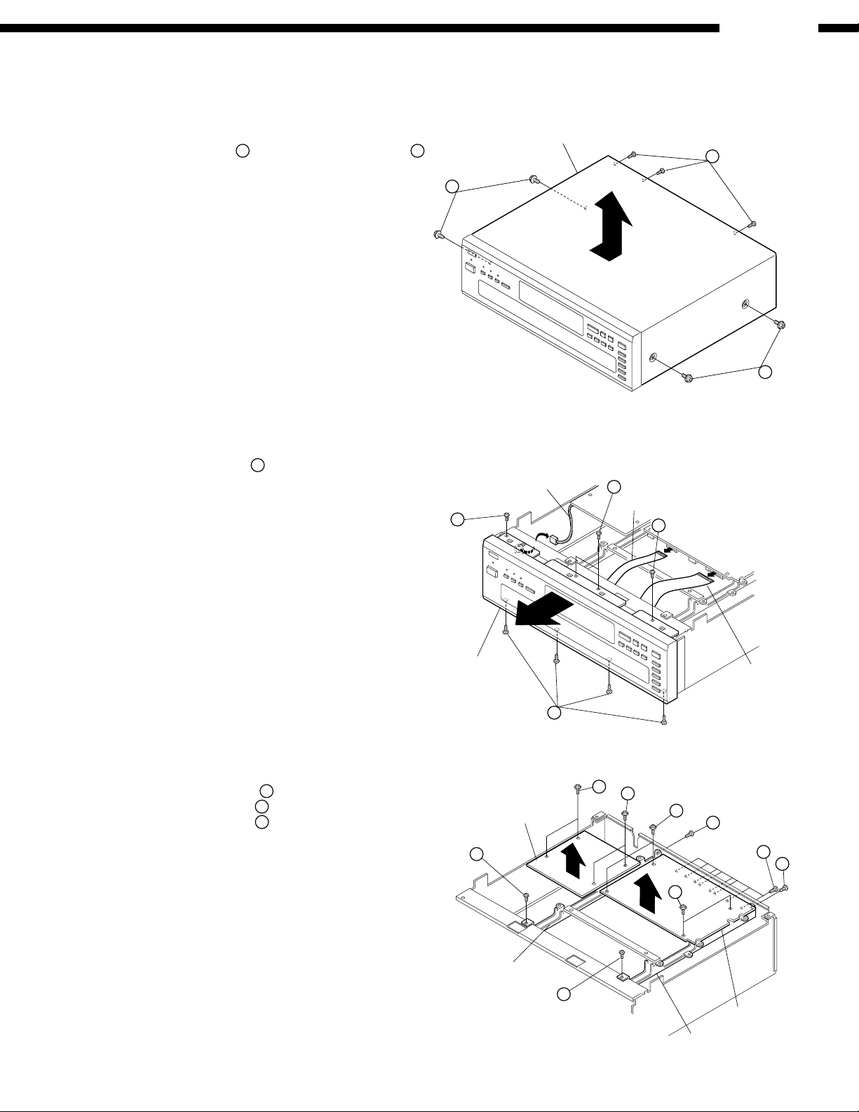
4. DISASSEMBLY
(Follow the procedure below in reverse order when reassembling)
DVM-4800
4.1 Top Cover
Remove 4 screws 1 on both sides and 3 screws
on the rear, then detach the Top Cover as shown to
the arrow direction.
4.2 Front Panel
(1) Remove 8 screws 3 from the top and bottom edges
of the Front Panel.
(2) Detach the Front Panel to the arrow direction,
together with its Inner Panel.
Top Cover
2
1
Connector
3
2
1
Flexible Wire
3
3
4.3 Mother & Power P.W.B., Stay
(1) Remove 12 screws 4 to detach the Mother P.W.B.
(2) Remove 4 screws 5, to detach the Power P.W.B.
(3) Remove 4 screws
6
to detach 2 Stays.
Front Panel
Power P.W.B.
6
Stay
Flexible Wire
3
5
5
4
6
4
6
4
6
Mother P.W.B.
Stay
13

4.4 Loader Frame Ass'y
Remove 2 screws 7 to detach 2 Side Plates, then pull
out the Loader Frame in the arrow direction.
Note: Draw out the Loader Frame 1 ~ 2 cm and
turn the power off, before performing this step.
DVM-4800
4.5 DVD Mecha.
(1) Remove 5 screws 8 to detach the Rear Panel.
(2) Remove 4 screws 9 to detach the Clamp Base.
(3) Remove 4 fixed pin
Traverse Unit.
to detach the DVD
Side Plate
Rear Panel
7
Loader Frame
8
7
Side Plate
8
Clamp Base
9
9
8
DVD Traverse Unit
14
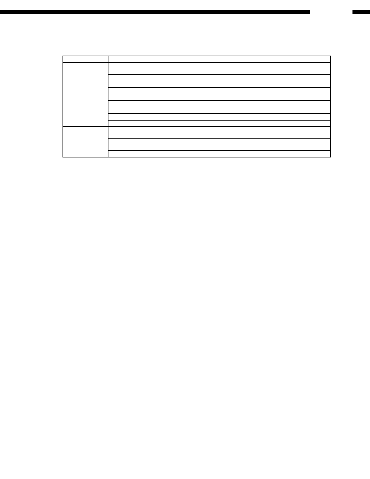
5. ADJUSTMENT PROCEDURES
5.1. Service Tools and Equipment
Application Name Number
Tilt adjustment DVD test disc DVDT-S15 or DVDT-S01
Hex wrench
Inspection Extension cable (module P.W.B. to mother P.W.B.) JGS0098
Extension cable (module P.W.B. to mother P.W.B.) VUC8026
Extension cable (module P.W.B. to mother P.W.B.) RFKZ0097
Extension cable (module P.W.B. to mother P.W.B.) VUC8026
Others Screw lock RZZ0L01
Grease RFKXGAK152
Oil RFKXGA1280, JZS0648
Confirmation CD test disc PVCD-K06 or any other commercially
available disc
VCD test disc PVCD-K06 or any other commercially
available disc
Recovery disc RFKZD5TR001
5.2. Important points in adjustment
5.2.1. Important points in optical adjustment
· Before starting optical adjustment, be sure to take anti-static measures.
· Optical pickup tilt adjustment is needed after replacement of the following components.
1. Optical pickup unit
2. Spindle motor unit
3. Optical pickup peripheral parts (such as rail)
Notes
Adjustment is generally unnecessary after replacing other parts of the traverse unit. However, make adjustment if there is a
noticeable degradation in picture quality. Optical adjustments cannot be made inside the optical pickup. Adjustment is generally
unnecessary after replacing the traverse unit.
5.2.2. Important points in electrical adjustment
· Follow the adjustment procedures described in this Manual.
5.3. Storing and Handling Test Discs
· Surface precision is vital for DVD test discs. Be sure to store and handle them carefully.
1. Do not place discs directly onto the workbench, etc., after use.
2. Handle discs carefully in order to maintain their flatness. Place them into their case after use and store them vertically. Store
discs in a cool place where they are not exposed to direct sunlight or air from air conditioners.
3. Accurate adjustment will not be possible if the disc is warped when placed on a surface made of glass, etc. If this happens, use
a new test disc to make optical adjustments.
4. If adjustment is done using a warped disc, the adjustment will be incorrect and some discs will not be playable.
DVM-4800
15
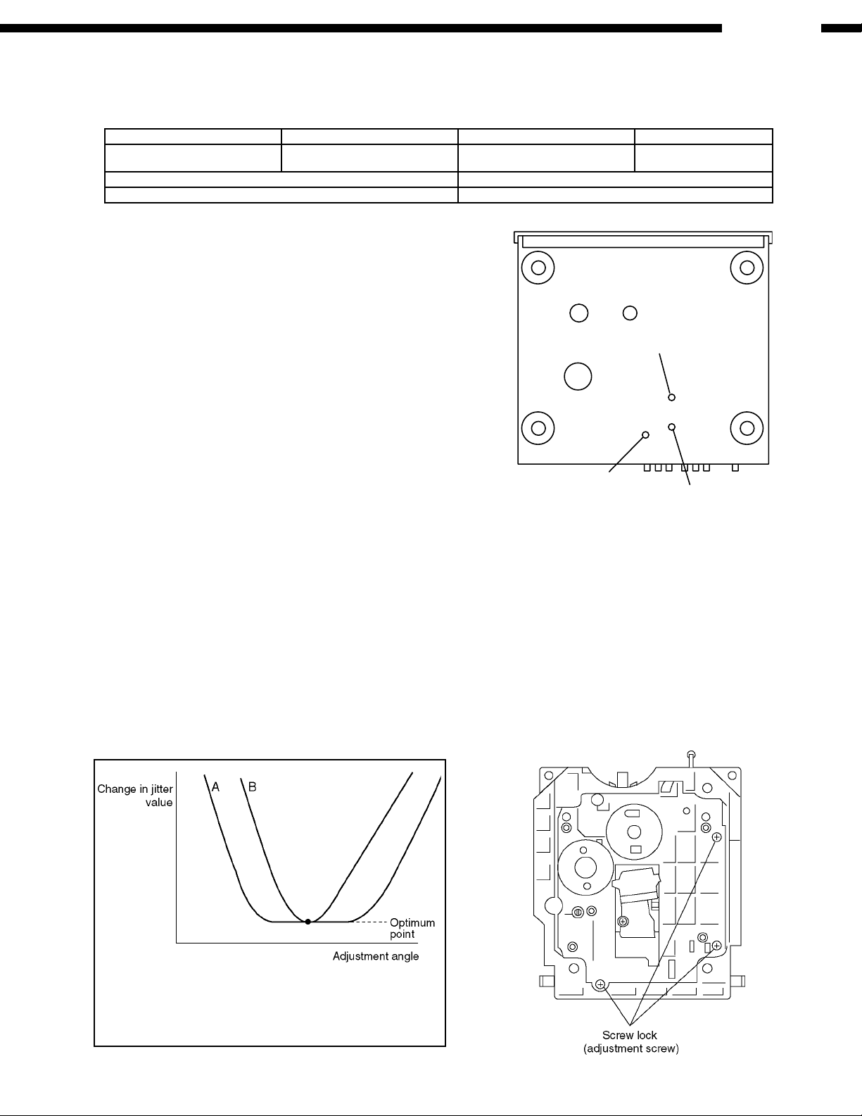
5.4.1.1. Adjustment procedure
1. While pressing PAUSE and OPEN/CLOSE buttons on the
Tangential Adjust Screw
Tilt Adjust Screw 2
Tilt Adjust Screw 1
main unit, press "5" on the remote control unit.
2. Confirm that "J_xxx_yyy_zz" is shown on the front display.
For your information:
"yyy" and "zz" shown to the right have nothing to do with
the jitter value. "yyy" is the error counter, while "zz" is
the focus drive value.
Note:
Jitter value appears on the front display.
3. Play test disc T01 (inner periphery).
4. Adjust tangential adjustment screw so that the jitter value is
minimized.
5. Play test disc T43 (outer periphery).
6. Adjust tilt adjustment screw 1 so that the jitter value is
minimized.
7. Play test disc T43 (outer periphery).
8. Adjust tilt adjustment screw 2 so that the jitter value is
minimized.
9. Repeat adjusting tilt adjustment screws 1 and 2 alternately
until the jitter value is minimized.
5.4.1.2. Important points
1. Make tangential adjustment first, and then make tilt
adjustment.
2. Repeat adjusting two or three times to find the optimum
point.
3. Finish the procedure with tilt adjustment.
Jitter value depends on the model:
1. If the jitter value changes like B, the optimum point is easy to
find.
2. If the jitter value changes like A, set the optimum point near the
middle.
5.4.1.3. Check after adjustment
Play test disc or any other disc to make sure there is no picture
degradation in the inner, middle and outer peripheries, and no
audio skipping. After adjustment is finished, lock each
adjustment screw in position using screw lock.
5.4.1.4. Procedure for screw lock
1. After adjustment, remove top cover, tray, clamper base and
traverse unit in this sequence.
2. Lay the traverse unit upside down, and fix adjustment screw
with screw lock.
3. After fixing, reassemble traverse unit, clamper base, tray
and top cover.
5.4. Optical adjustment
5.4.1. Optical pickup tilt adjustment
Measurement point Adjustment point Mode Disc
Tangential adjustment screw
Tilt adjustment screw
T01 (inner periphery) play
T43 (outer periphery) play
DVDR-S15 or DVDT-S01
Measuring equipment Adjustment value
None (Main unit display for servicing is used.) Adjust to the minimum jitter value.
Front Side
DVM-4800
16
DVM-4800
Do this confirmation after replacing a P.W.B.
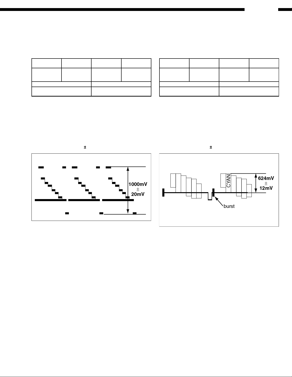
5.5.1. Video Output (Luminance Signal)
Adjustment
Measurement
Point
Adjustment
Point
Mode Disc
Video Output
Pin Terminal
GND: Chassis
VR3225 Playback
(Color Bar)
DVDT-S20
(title 9)
Measuring Device Adjustment Value
Oscilloscope
500 mV/div, 10 µs/div
1000 ± 20mV p-p
For compatibility of video signal output.
1. Connect the monitor TV to the video output terminal and
terminate at 75 Ohms.
2. Play back the color bar part title 9 (DVDT-S20) of the DVD
Test Disc title.
3. Adjust the VR3225 so that the luminance signal output is as
shown below.
Adjustment Value = 1000 20 mV p-p
Fig. 5-5-1 Luminance Signal Output
5.5.2. Video Output (Chrominance
Signal) Adjustment
Measurement
Point
Adjustment
Point
Mode Disc
Video Output
Pin Terminal
GND: Chassis
VR3221 Playback
(Color Bar)
DVDT-S20
(title 9)
Measuring Device Adjustment Value
Oscilloscope
500 mV/div, 10 µs/div
624 ± 12mV p-p
For compatibility of video signal output.
1. Connect the monitor TV to the video output terminal and
terminate at 75 Ohms.
2. Play back the color bar part title 9 (DVDT-S20) of the DVD
Test Disc title.
3. Adjust the VR3221 so that the chrominance (CYAN) signal
output is as shown below.
Adjustment Value = 624 12 mV p-p
Fig. 5-5-2 Chrominance Signal Output
5.5. Electrical Adjustment
17
DVM-4800
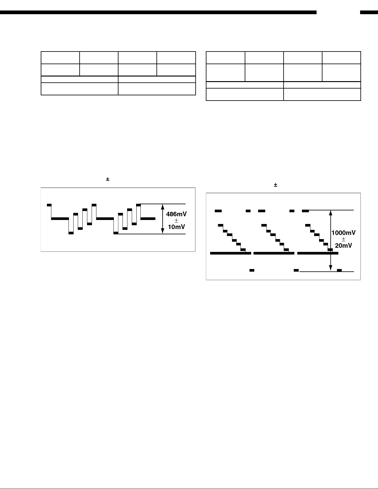
5.5.3. Video Output (CB Signal)
Adjustment
Measurement
Point
Adjustment
Point
Mode Disc
CB Output Pin
Terminal
VR3201 Playback
(Color Bar)
DVDT-S20
(title 9)
Measuring Device Adjustment Value
Oscilloscope
200 mV/div, 10 µs/div
486 ± 10mV p-p
NOTE:
CB/CR Output should be 75Ω terminate.
For compatibility of video signal output.
1. Connect the monitor TV to the video output terminal and
terminate at 75 Ohms.
2. Play back the color bar part title 9 (DVDT-S20) of the DVD
Test Disc title.
3. Adjust the VR3201 so that the CB signal output is as shown
below.
Adjustment Value = 486 10 mV p-p
Fig. 5-5-3 CB Signal Output
5.5.4. Progressive Video Output
(Y Signal) Adjustment
Measurement
Point
Adjustment
Point
Mode Disc
Progressive
Terminal
GND: Chassis
VR3771 Playback
(Color Bar)
DVDT-S20
(title 9)
Measuring Device Adjustment Value
Oscilloscope
200 mV/div, 5 µs/div
1000 ± 20mV p-p
NOTE:
Progressive Output should be 75Ω terminate.
For compatibility of video signal output.
1. Connect the monitor TV to the Y (Progressive) output
terminal and terminate at 75 Ohms.
2. Play back the color bar part title 9 (DVDT-S20) of the DVD
Test Disc title.
3. Adjust the VR3771 so that the Y (Progressive) signal output
is as shown below.
Adjustment Value = 1000 20 mV p-p
Fig. 5-5-4 Y Signal Output
18
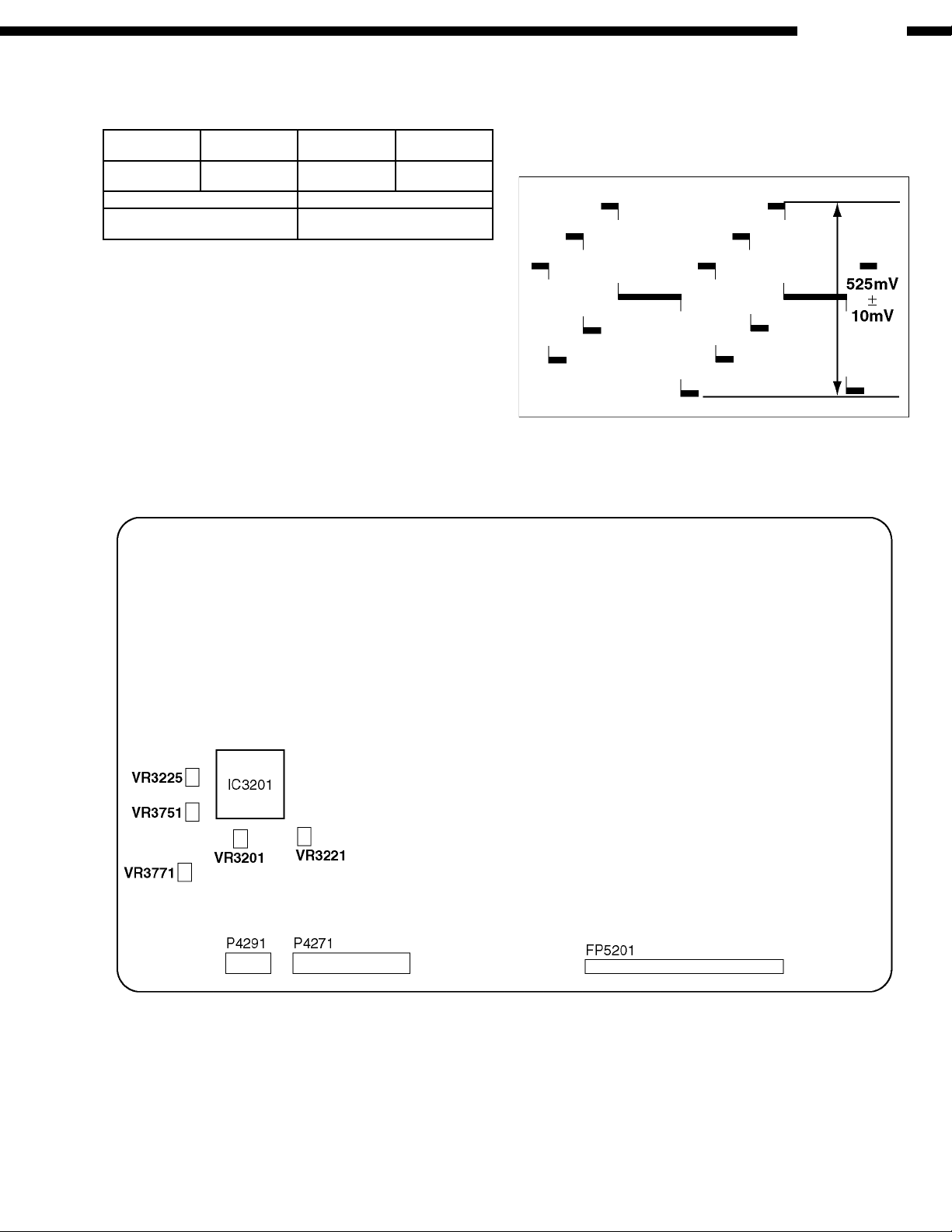
5.5.5. Progressive Video Output
(PB Signal) Adjustment
Measurement
Point
Adjustment
Point
Mode Disc
Progressive
Terminal
VR3751 Playback
(Color Bar)
DVDT-S20
(title 9)
Measuring Device Adjustment Value
Oscilloscope
100 mV/div, 5 µs/div
525 ± 10mV p-p
NOTE:
Progressive Output should be 75Ω terminate.
For compatibility of video signal output.
1. Connect the monitor TV to the video output terminal and
terminate at 75 Ohms.
2. Play back the color bar part title 9 (DVDT-S20) of the DVD
Test Disc title.
3. Adjust the VR3751 so that the PB signal output is as shown
below.
Fig. 5-5-5 PB Signal Output
5.5.6. Test Point & Controls Location
MODULE P.W.B. (COMPONENT SIDE)
DVM-4800
19
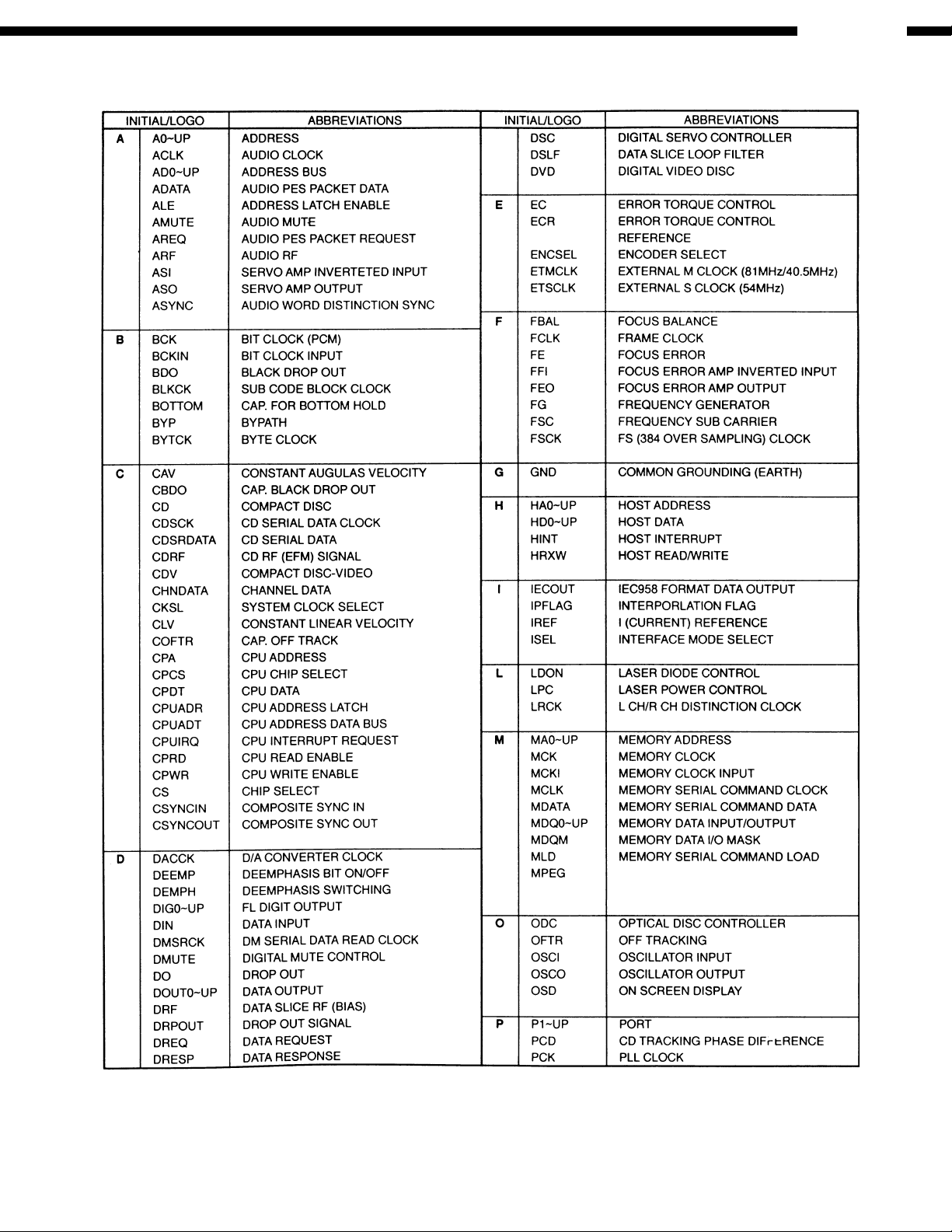
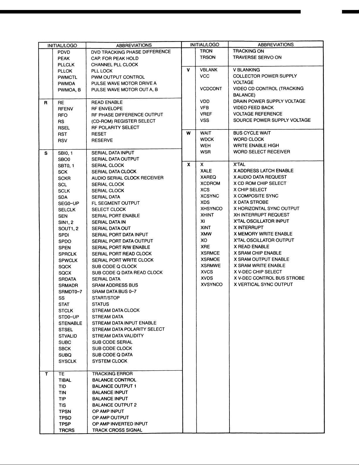
6. ABBREVIATIONS
DVM-4800
MOVING PICTURE EXPERTS GROUP
20
DVM-4800
21
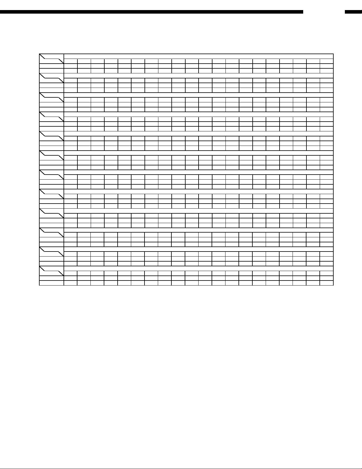
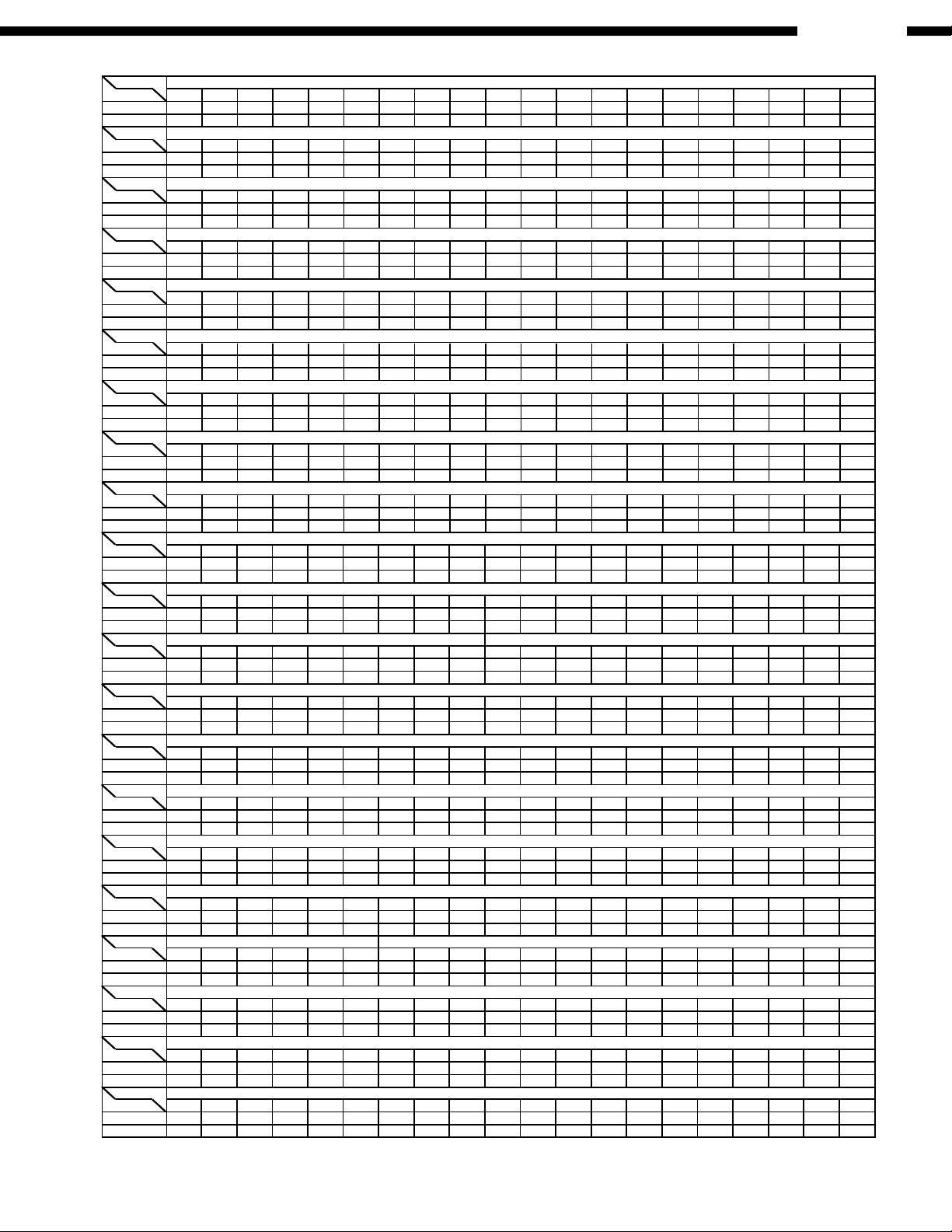
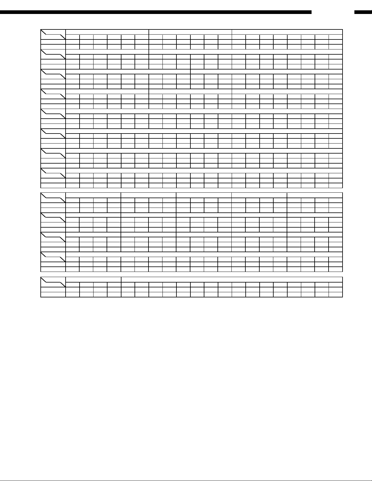
7. VOLTAGE CHART
Ref No.
MODE
STOP
PLAY
Ref No.
MODE
STOP
PLAY
Ref No.
MODE
STOP
PLAY
Ref No.
MODE
STOP
PLAY
Ref No.
MODE
STOP
PLAY
Ref No.
MODE
STOP
PLAY
Ref No.
MODE
STOP
PLAY
Ref No.
MODE
STOP
PLAY
Ref No.
MODE
STOP
PLAY
Ref No.
MODE
STOP
PLAY
Ref No.
MODE
STOP
PLAY
Ref No.
MODE
STOP
PLAY
IC2001
IC2001
IC2001
IC2001
1 2 3 4 5 6 7 8 9 1011121314 151617181920
0 3.3 3.3 0 3.3 3.3 0 0
0 3.3 3.3 0 3.3 3.3 0 0 1.9 2.1 0 0 0 0 3.3
1.9 2.3 2.2 2.2 2.3 2.4 2.3 2.2 2.4 1.8 0 1.8
1.8 2.2 1.8 0 1.8
IC2501
12345678 91011121314151617181920
1.7 1.7 1.7 1.7 1.7 0.1 0 5.0 0 0
1.7 1.7 1.7 1.7 1.7
IC2502
12345
1.7 1.7 0 0 4.9
004.91.7 1.7
0.1 0 5.0 3.3 0
2.9 2.9 2.9 2.9 4.4 4.4 4.4 4.4 0 3.1
2.9 2.9 2.9 2.9 3.6 4.4 5.9 2.5 0 3.1
37 38 39 40
3.2 3.2 3.2 3.2
2.8 2.8 2.7 2.7
30 31 32 33 34 35 3621 22 23 24 25 26 27 28 29
0 2.3 2.2 3.0 2.5 3.0 2.6 3.3 3.3 3.3 3.3
0 1.9 2.0 2.7 2.2 2.6 2.6 1.7 2.5 1.4 3.3
0 3.3 3.3
0 3.3 3.3
3.3 3.3
3.3 3.3
57 58 59 60
3.3 1.8 0 0
3.3 1.8 0 0
50 51 52 53 54 55 5641 42 43 44 45 46 47 48 49
3.2 3.2 3.2 2.0 1.5 0 3.2 0
2.6 2.7 2.6 2.6 1.5 0 3.2 0
3.3 3.3 3.3
3.3 3.3 0
0 3.3 3.3
0 3.3 0
00
00
77 78 79 80
0 3.3 1.5 1.5
70 71 72 73 74 75 7661 62 63 64 65 66 67 68 69
3.2 3.3 0 0 1.8 2.0 1.6 1.6
3.2 3.3 3.3 0 2.1 1.0 1.6 2.2
3.3 0 0
1.3 3.3 3.3
001.8
0
3.3 3.3
0 3.3 1.5 1.501.83.3 3.3
IC2001
97 98 99 100
1.4 1.6 3.3 1.4
90 91 92 93 94 95 9681 82 83 84 85 86 87 88 89
0 0 0 1.6 0 1.7 1.7 3.3 0 1.6
0 0 0 1.6 0 1.7 1.7 3.3 0 1.6
1.6 0 1.7 1.600
1.4 1.6 3.3 1.41.6 0 1.7 1.600
IC2001
117 118 119 120
1.7 1.6 1.7 1.7
110 111 112 113 114 115 116101 102 103 104 105 106 107 108 109
1.4 0 1.5 2.1 2.8 1.7 1.6 1.5 3.3
1.4 0 1.5 2.1 2.8 1.7 1.6 1.5 3.3
1.6
1.6
1.6 2.7 1.7 3.301.7
1.7 1.6 2.1 2.51.7 3.31.71.6 2.2 0
IC2001
137 138 139 140
3.3 0 3.3 0
130 131 132 133 134 135 136121 122 123 124 125 126 127 128 129
2.3 1.7 1.7 0 3.3 0 1.2 1.3 1.3
2.1
1.3
1.7 1.7 0 3.3 0 1.4 1.3 1.3 1.3
3.3 3.3 3.3 1.703.3
3.3 0 3.3 03.3 3.3 3.3 1.703.3
IC2001
157 158 159 160
0003.3
150 151 152 153 154 155 156141 142 143 144 145 146 147 148 149
0 3.3 3.3 0 0 1.6 3.3 3.3 0
0.403.3 3.3 0 0 1.6 3.3 3.3 0.9 0
3.3 1.8 0 3.300
0 1.0 01.8 0 3.300 0.90.6
IC2001
170 171 172 173 174 175 176161 162 163 164 165 166 167 168 169
0 3.3 0 0 0 3.3 0 3.3 3.3
0 3.3 0 0.8 0 0.7 0 1.0 3.300
00 3.33.303.3
3.33.30.8 3.300
IC2501
21 22 23 24 25 26 27 28
9.2 9.2 1.7 1.6 1.6 1.7 0
9.2 9.2 1.9 1.6 1.6 1.7 3.3
3.1
3.1
Main P.W.B.
DVM-4800
22

DVM-4800
Ref No.
MODE
STOP
PLAY
Ref No.
MODE
STOP
PLAY
Ref No.
MODE
STOP
PLAY
Ref No.
MODE
STOP
PLAY
Ref No.
MODE
STOP
PLAY
Ref No.
MODE
STOP
PLAY
Ref No.
MODE
STOP
PLAY
Ref No.
MODE
STOP
PLAY
Ref No.
MODE
STOP
PLAY
Ref No.
MODE
STOP
PLAY
Ref No.
MODE
STOP
PLAY
Ref No.
MODE
STOP
PLAY
Ref No.
MODE
STOP
PLAY
Ref No.
MODE
STOP
PLAY
Ref No.
MODE
STOP
PLAY
Ref No.
MODE
STOP
PLAY
Ref No.
MODE
STOP
PLAY
Ref No.
MODE
STOP
PLAY
Ref No.
MODE
STOP
PLAY
Ref No.
MODE
STOP
PLAY
Ref No.
MODE
STOP
PLAY
IC3001
IC3001
IC3001
IC3001
1 2 3 4 5 6 7 8 9 1011121314 151617181920
3.3 0 1.2 0.1 1.8 1.2 0.1 1.0 0 1.2 3.3 3.4 3.3 0 1.7 1.8 3.3 3.4 2.3
3.3 0 1.6 0.1 1.8 1.7 0.1 1.6 0 1.6 3.3 3.4 3.3 0 0 1.8 2.8 3.4 000
37 38 39 40
1.8 2.3 2.3 3.3
30 31 32 33 34 35 3621 22 23 24 25 26 27 28 29
0 0 3.3 0 3.4 1.4 3.3 3.3 0 1.5 0
3.3
2.5 2.3 2.43.5 2.2
1.8 1.9 1.8 2.13.3 3.1 3.3 3.4 1.4 0.2 2.6 1.7 3.3 0 2.1 1.9 2.22.7 2.2
57 58 59 60
1.8 3.1 3.2 3.1
1.8 2.6 2.6 2.7
50 51 52 53 54 55 5641 42 43 44 45 46 47 48 49
3.3 3.3 0 2.2 2.3 2.1 2.9 3.3
1.8 1.7 0 2.0 2.1 1.9 2.8 3.3
3.1 3.1 3.1
2.6 2.8 2.8
3.1 3.1 3.1
2.8 2.8 2.8
03.1
02.8
IC3061
IC3061
IC3061
1 2 3 4 5 6 7 8 9 1011121314 151617181920
3.3 2.8 0 2.7 2.8 0 2.7 3.0 3.3
2.6 3.1 2.7 2.8 0 2.9 3.0 3.3
2.7 2.8 0 2.8 3.3 2.5 0 3.2 3.3 3.1
3.3
IC3091
12345678
1.6 1.9 1.9 0 1.5 1.5 2.1 4.8
1.9 1.9 0 1.5 1.5 2.1 4.81.6
2.9
1.0
2.8 0 2.8 3.3 2.5 3.3 3.2 3.3 3.1 0
37 38 39 40
3.3 1.7 2.4 0
30 31 32 33 34 35 3621 22 23 24 25 26 27 28 29
0 0 0 0 0 1.1 3.3 0 1.0 1.1
0 0 0 0.3 1.6 3.3 0 1.4 1.6
1.1
0.3
1.1 1.4 000
3.3 1.7 1.9 01.6 1.4 1.4 000
50 51 52 53 5441 42 43 44 45 46 47 48 49
0 2.9 3.3 2.6 2.6 0 2.6 3.003.3 2.4 2.4 0 2.9 0
2.9 3.3 2.8 2.7 0 2.8 2.8 3.3 2.9 2.9 0 2.2 0
77 78 79 80
1.8 3.3 3.3 3.3
70 71 72 73 74 75 7661 62 63 64 65 66 67 68 69
3.4 3.1 3.1 0 3.2 3.1 3.2 3.4
3.4 2.8 2.8 0 2.9 2.9 2.9 3.3
0 1.7 3.4
0.5 1.7 3.4
003.3
0
03.3
1.8 1.1 1.0 1.00.8 1.60.8 0.8
IC3001
97 98 99 100
1.8 0 1.8 1.5
90 91 92 93 94 95 9681 82 83 84 85 86 87 88 89
3.3 0 1.7 0 3.4 1.6 1.7 1.7 0 0
0.8 0 1.7 0.8 3.3 1.8 1.7 1.7 0 0.8
00 1.61.73.4 0
1.8 0 1.8 1.500 01.73.4 0
IC3001
117 118 119 120
3.4 0 0.1 3.0
110 111 112 113 114 115 116101 102 103 104 105 106 107 108 109
3.4 0 0 0 3.4 1.6 1.8 0 3.3
3.4 0 0.2
0 0 3.3 2.9 000
3.3 0 0 3.30 3.4 1.6 1.8 0 3.3 0 0 3.3 2.9 000
IC3001
137 138 139 140
000 0
130 131 132 133 134 135 136121 122 123 124 125 126 127 128 129
0 3.4 0 0.1 3.4 0 0 0 0 3.3 0 0 0 1.600
0000 0 0 0.1 3.4 0 3.3 0 0 2.9 0 0 0 1.600 0
IC3001
157 158 159 160
0 2.8 2.9 3.3
150 151 152 153 154 155 156141 142 143 144 145 146 147 148 149
3.4 0 0 3.3 3.1 1.8 1.3 0.6 0.7 0.7 0 2.0 1.3 00.3 0.3
0 2.2 2.93.4 0 0 3.3 3.1 1.8 1.3 1.2 1.3 1.3 0 1.6 1.2 3.31.1 1.5 3.3
IC3001
170 171 172 173 174 175 176161 162 163 164 165 166 167 168 169
2.6 2.8 0 2.7 2.7 3.3 3.0 2.8 0
3.1
2.8 3.1 3.3 2.9 02.7 1.8
177 178 179 180
3.3 2.92.8 2.7
IC3001
190 191 192 193 194 195 196181 182 183 184 185 186 187 188 189
2.8 0 1.7 1.8 1.7 0 3.4 3.4 2.6
2.8
IC3001
201 202 203 204 205 206 207 208
0 1.8 1.2 0 0 1.1 0 0
1.8 1.4 0 3.3 0 1.5 00
0.1
0 1.7 1.8 1.7 0 3.4 3.4 2.2 0.2
1.8 2.5 3.2 3.23.3 0
197 198 199 200
3.0 03.3 1.5
1.8 1.9 3.2 3.23.3 0 3.0 03.3 1.3
2.8 0 0 2.7 3.3 3.0 - 0 - 2.6 3.3 2.6 00 1.8 3.3 2.62.8 -
IC3201
IC3201
IC3201
IC3201
12345678 91011121314151617181920
1.4 0.6 0.7 0.7 2.0 0.3 0.3 1.4 3.3 3.3
1.4 1.3 1.3 1.1 1.6 1.2 1.6 1.2 3.3 3.3
3.3 0
3.3
3.3
3.3
3.3
3.3
3.3
3.3
3.3
3.3
3.3
3.3
IC3261
12345678 910111213141516
1.3 1.5 1.3 1.5 1.5 0 0 0 0 0
1.3
IC3251
123456
4.8 0 4.8 1.3 0 3.3
0 4.8 1.3 0 3.34.8
0 1.0 1.2 1.0 1.5 4.8
1.5 1.3 1.5 1.5 0 0 0 0 0 0 1.2 1.4 1.2 1.5 4.8
3.3
3.3
3.3
3.3
3.3
3.30
37 38 39 40
0.4 3.3 0 0
30 31 32 33 34 35 3621 22 23 24 25 26 27 28 29
3.3 0 0 0 3.0 3.0 0 0 1.3 1.6
0 0 0 3.3 0 1.6 0 3.3 3.0
0.5
3.3
0.4 0 0.83.3 0
0.6 3.3 0 03.0 0 0.5 0.501.3
57 58 59 60
000 0
50 51 52 53 54 55 5641 42 43 44 45 46 47 48 49
0.8 0 3.3 0.8 0 1.6 1.3 1.3 3.2 3.1
0.8 0 3.3 0.8 0 1.6 1.3 1.3 3.2 3.1
3.3 0 0 003.3
000 03.3 0 0 003.3
61 62 63 64
003.3
003.300
23

DVM-4800
Ref No.
MODE
STOP
PLAY
Ref No.
MODE
STOP
PLAY
Ref No.
MODE
STOP
PLAY
Ref No.
MODE
STOP
PLAY
Ref No.
MODE
STOP
PLAY
Ref No.
MODE
STOP
PLAY
Ref No.
MODE
STOP
PLAY
Ref No.
MODE
STOP
PLAY
Ref No.
MODE
STOP
PLAY
Ref No.
MODE
STOP
PLAY
Ref No.
MODE
STOP
PLAY
Ref No.
MODE
STOP
PLAY
Ref No.
MODE
STOP
PLAY
Ref No.
MODE
STOP
PLAY
Ref No.
MODE
STOP
PLAY
Ref No.
MODE
STOP
PLAY
Ref No.
MODE
STOP
PLAY
Ref No.
MODE
STOP
PLAY
Ref No.
MODE
STOP
PLAY
Ref No.
MODE
STOP
PLAY
Ref No.
MODE
STOP
PLAY
IC3701
IC3701
IC3701
IC3701
1 2 3 4 5 6 7 8 9 1011121314 151617181920
3.4 0 3.4 0 0 0 3.4 3.4 3.1 3.4
3.4 0 3.4 0 0 0 3.4 3.4 3.1 3.4
0 2.8 3.3 3.1 0.8 0 0 0 0 0
0 0.6 3.3 3.1 2.8 0 0 0 1.3 1.3
37 38 39 40
0.9 0.6 0.6 3.4
30 31 32 33 34 35 3621 22 23 24 25 26 27 28 29
0 0 3.3 0 0 0 3.3 2.3 0
1.0 0.6 3.3 2.2 1.9 2.4 1.4 0 0
0 3.4 0 0.9 0.91.9 0.6
0.5 0.5 3.3 3.43.4 0 1.3 1.31.2 1.10
57 58 59 60
003.40
50 51 52 53 54 55 5641 42 43 44 45 46 47 48 49
2.7 0 0 0 0.9 0.5 0.5 0.5 3.4 1.6
3.3 0 0 0 1.2 1.2 1.2 1.2 3.4 1.6
00 003.3 0
003.4000 2.10.22.0 0.9
77 78 79 80
0 1.7 1.7 1.7
70 71 72 73 74 75 7661 62 63 64 65 66 67 68 69
1.6 3.4 0 0 3.4 0 3.3 3.3 0 1.6
1.6 3.4 0 0 3.4 0 3.3 3.3 0 1.6
3.4 3.3 1.5 1.70.7 0
0 1.7 1.7 1.73.4 3.3 0.6 1.70.7 0
IC3701
97 98 99 100
0.9 1.4 0 0
90 91 92 93 94 95 9681 82 83 84 85 86 87 88 89
3.4 1.7 1.6 1.7 1.8 2.2 0 0 3.3 1.1
3.4 1.7 1.6 1.7 2.1 2.2 3.3 0 0 1.1
0.9 2.1 0.9 3.42.1 2.1
1.3 1.2 0 01.7 2.4 1.3 3.42.2 2.3
IC3731
IC3731
IC3731
IC3731
1 2 3 4 5 6 7 8 9 1011121314 151617181920
1.4 3.3 1.4 1.2 0 1.2 2.3 3.3 2.6 1.7
1.2 3.3 1.6 1.6 0 1.6 1.9 3.3 2.2 2.2
0 1.9 1.9 3.3 3.3 0 1.9 1.8 0 1.7
3.3 3.3 0 2.2 1.8 0 2.10 2.0 2.0
37 38 39 40
000 0
30 31 32 33 34 35 3621 22 23 24 25 26 27 28 29
2.8 3.3 0.6 0.6 3.3 3.3 3.3 0 2.2
2.5 3.3 0.6 0.6 3.3 3.3 3.3 0 2.2
0 1.6 1.6 3.3 01.6 1.6
000 01.6 1.6 3.3 01.6 1.60
57 58 59 60
0 1.7 3.3 1.0
50 51 52 53 54 55 5641 42 43 44 45 46 47 48 49
0 0 0 0 0 0 1.6 1.7 1.7 1.7
0 0 0 0 0 0 1.6 1.7 1.7 1.7
2.1 0 0 0.603.3
0 1.7 3.3 1.62.1 0 1.6 0.603.3
IC3751
IC3751
IC3751
1 2 3 4 5 6 7 8 9 1011121314 151617181920
0 0 0 0.9 0.5 0.5 0.5 3.3 0.1 0.1
3.3 0 0 1.2 1.2 1.2 1.3 2.2 1.3 2.1
IC4201IC3781
123456
4.8 0 4.8 1.3 0 3.3
4.8 0 4.8 1.3 0 3.3
123
0 3.3 4.7
0 3.3 4.7
0 3.5 0 0 0 1.8 0.8 1.1 1.8 0
3.5 0 0 0 1.3 1.3 1.3 1.2 0.50.2
37 38 39 40
1.7 1.6 1.6 3.2
30 31 32 33 34 35 3621 22 23 24 25 26 27 28 29
1.2 1.2 1.2 3.3 1.6 0 2.6 3.3 3.1 3.0
0.5 0.5 3.2 3.3 1.6 0 2.6 3.3 3.1 3.0
3.0 0.6 3.3 0.600.4
1.7 1.6 1.6 3.23.0 0.5 3.3 0.600.7
IC4211
IC4211
1 2 3 4 5 6 7 8 9 1011121314 151617181920
1.7 0 1.6 0 1.5 0 3.3 0 0 4.7
1.7 0.8 1.6 0 1.5 0 3.3 0 0 4.7
0 2.3 2.4 0 4.7 2.4 2.3 0 4.7 0
0 2.3 2.4 0 4.7 2.4 2.3 0 4.7 0
21 22 23 24 25 26 27 28
0 3.2 3.3 3.3 0 3.3 2.8 3.3
3.2 0 0 0 3.3 2.8 3.30
IC4221
IC4221
1 2 3 4 5 6 7 8 9 1011121314 151617181920
1.7 0 1.6 1.9 1.5 3.7 0 4.7 4.7 0
1.7 0.8 1.6 1.9 1.5 3.7 0 4.7 4.7 0
2.3 0 2.3 0 4.7 2.4 0 2.3 0 4.7
2.3 0 2.3 0 4.7 2.4 0 2.3 0 4.7
21 22 23 24 25 26 27 28
0 3.2 0 4.7 4.8 3.3 2.8 3.3
3.2 0 4.7 4.6 3.3 2.8 3.34.9
50 51 5241 42 43 44 45 46 47 48 49
3.3 3.3 0 0.1 0.3 0.6 0.7 0.5 0 0 0
3.3 0 0 0.1 0 0 0.1 0 0 0 0
0.1
0.1
77 78 79 80
003.33.1
70 71 72 73 74 75 7661 62 63 64 65 66 67 68 69
0 0 0.9 0.9 3.3 0 3.3 0 0 0
1.6 0 1.6 1.6 3.3 0 3.3 1.9 1.7 0
00.9 1.703.3 0
2.2 2.2 3.3 2.42.3 0.9 2.2 03.3 2.2
IC3731
97 98 99 100
1.4 0.9 0 2.2
90 91 92 93 94 95 9681 82 83 84 85 86 87 88 89
1.5 0 1.5 1.4 0 0 0 0 0 0
2.2 0 2.9 1.7 0 0 0 0 0 3.3
00 03.300
1.6 1.7 0 1.73.3 0 0 3.300
IC3701
117 118 119 120
1.8 1.6 3.0 2.2
110 111 112 113 114 115 116101 102 103 104 105 106 107 108 109
3.4 1.0 0.9 0.9 0.9 1.6 1.9 1.9 1.8 2.7
3.4 1.2 1.2 1.2 1.2 1.3 2.4 2.6 1.1 2.2
0 1.8 3.4 2.02.1 2.0
2.5 2.6 1.9 2.20 2.2 3.4 2.82.4 2.0
IC3701
137 138 139 140
000 0
130 131 132 133 134 135 136121 122 123 124 125 126 127 128 129
1.8 0 1.8 1.8 1.7 1.6 1.6 1.5 2.0 3.4 0 0 0 000
0002.2 0 2.2 2.2 2.4 2.6 2.6 1.7 2.0 3.4 0 0 0 000 0
IC3701
157 158 159 160
1.6 2.9 2.9 2.9
150 151 152 153 154 155 156141 142 143 144 145 146 147 148 149
0 0 0 0 0 0.6 0.7 0.6 0 0 0 0 0 1.3 1.1 1.2 1.6
0 3.4 0.3 0 3.40.3 -
1.6 2.9 2.9 2.3.4 1.3 0 3.41.4 1.20
24
DVM-4800
Ref No.
MODE
STOP
PLAY
Ref No.
MODE
STOP
PLAY
Ref No.
MODE
STOP
PLAY
Ref No.
MODE
STOP
PLAY
Ref No.
MODE
STOP
PLAY
Ref No.
MODE
STOP
PLAY
Ref No.
MODE
STOP
PLAY
Ref No.
MODE
STOP
PLAY
Ref No.
MODE
STOP
PLAY
Ref No.
MODE
STOP
PLAY
Ref No.
MODE
STOP
PLAY
Ref No.
MODE
STOP
PLAY
Ref No.
MODE
STOP
PLAY
Ref No.
MODE
STOP
PLAY
Ref No.
MODE
STOP
PLAY
Ref No.
MODE
STOP
PLAY
Ref No.
MODE
STOP
PLAY
Ref No.
MODE
STOP
PLAY
Ref No.
MODE
STOP
PLAY
Ref No.
MODE
STOP
PLAY
Ref No.
MODE
STOP
PLAY
IC4231
IC4231
1 2 3 4 5 6 7 8 9 101112 1314 1516171819 20
1.7 0 1.6 1.9 1.5 3.6 0 4.7 4.7 0
1.7 0 1.6 1.9 1.5 3.6 0 4.7 4.7 0
2.3 0 2.4 0 4.7 2.4 0 2.3 0 4.7
2.3 0 2.4 0 4.7 2.4 0 2.3 0 4.7
21 22 23 24 25 26 27 28
0 3.2 0 4.7 4.7 3.3 2.8 3.3
0 3.2 0 4.7 4.7 3.3 2.8 3.3
IC4241
IC4241
1 2 3 4 5 6 7 8 9 101112 1314 1516171819 20
1.7 0 1.6 1.9 1.5 3.6 0 4.7 4.7 0
1.7 0 1.6 1.9 1.5 3.6 0 4.7
IC4261
12345678
00000005.0
4.9 0 4.9 0 0 4.9 4.9 4.9
IC5262
12345678
2.2 2.2 2.2 0 2.2 2.2 2.2
2.2 2.2 2.2 0 2.2 2.2 2.2
4.9
IC5266
12345678
1.7 4.2 0 0 1.1 0 004.8
0000 0 04.8
IC5267
12345678
1.7 0 0 0 1.0 0 0
01.9
4.9
1.8 0 0 0 0 0
IC6211
12345
0 0 0 3.3 3.3
0 0 0 3.3 3.3
IC6221
12345678
0 0 0 0 3.0 3.0 0 3.3
0 0 0 0 3.0 3.0 0 3.3
4.9
4.7 0
2.3 0 2.4 0 4.7 2.4 0 2.3 0 4.7
2.3 0 2.4 0 4.7 2.4 0 2.3 0 4.7
21 22 23 24 25 26 27 28
0 3.2 0 4.7 4.7 3.3 2.8 3.3
0 3.2 0 4.7 4.7 3.3 2.8 3.3
IC5201
IC5201
IC5201
IC5201
1 2 3 4 5 6 7 8 9 101112 1314 1516171819 20
0 4.4 0 4.4 0 1.7 1.7 1.7 3.3 0
0.5 3.2 0 4.4 0 1.7 1.7 2.0 3.3 0
3.2 3.3 0 0 1.2 1.7 1.7 1.7 1.7 1.7
3.2 3.3 0 0 1.2 1.7 1.7 1.7 1.7 2.1
37 38 39 40
1.2 0 3.3 0
30 31 32 33 34 35 3621 22 23 24 25 26 27 28 29
1.7 1.7 2.7 0 1.7 0 2.2 4.8 1.7 1.8
1.7 1.7 2.7 0 1.7 0 2.2 4.8 1.7 1.8
1.8 2.1 1.5 3.302.1
1.2 0 0 01.8 2.1 1.5 3.302.1
57 58 59 60
2.2 2.2 2.2 2.2
50 51 52 53 54 55 5641 42 43 44 45 46 47 48 49
1.7 1.6 1.6 1.1 1.7 2.2 2.2 2.2 2.2 2.1
2.5 1.4 1.8 2.2 1.9 2.2 2.2 2.2 2.2 2.1
2.2 2.1 4.8 2.22.2 2.3
2.2 2.2 2.2 2.22.2 2.1 4.8 2.22.2 2.3
IC5263
12345678 910111213141516
0 1.7 2.2 2.2 2.2 0 0 0 3.3 0 0.2 1.1 1.1 1.7 4.9
0 0 0 0 0 0 0 0 3.3 0 0 2.2 0.1 2.2 2.0
4.9
4.9
61 62 63 64
0 2.2 2.2
0 2.2 2.200
IC6201
IC6201
IC6201
IC6201
12345678 91011121314151617181920
3.3 3.1 3.3 3.3 3.3 3.3 3.3 3.0 3.3 0
3.3 2.7 3.3 3.3 3.3 3.3 3.3 2.5 0 0
0 3.3 2.1 3.0 3.0 2.8 3.3 3.3 0 0
0 0.1 1.4 2.6 1.7 1.4 3.3 3.3 0 0
37 38 39 40
1.7 0 0 0
30 31 32 33 34 35 3621 22 23 24 25 26 27 28 29
3.3 3.3 1.5 1.8 3.3 3.0 2.5 3.0 2.2 2.3
3.3 3.3 1.5 1.8 3.3 2.6 2.1 0 0 1.9
2.4 2.2 2.4 2.22.2 3.3
1.7 2.0 2.1 1.92.4 1.9 2.2 1.82.0 3.3
57 58 59 60
3.3 0 0 3.3
50 51 52 53 54 55 5641 42 43 44 45 46 47 48 49
000.500000 03.3
1.8 1.4 0.5 0 1.4 0 0 0 0 3.0
3.3 3.3 3.3 3.33.3 2.1
3.3 0 0 3.32.8 3.3 3.03.0 1.91.1
IC6301
IC6301
IC6301
12345678 91011121314151617181920
2.2 2.2 2.1 2.2 2.4 2.2 2.2 2.5 2.0 2.0
2.2 2.0 1.7 1.7 2.1 1.9 1.9 2.2 1.4 1.4
3.3 3.3 0 3.3 2.0 2.0 2.3 2.3 2.2 3.0
2.6 3.3 0 3.3 3.3 1.3 1.7 1.9 2.2 2.7
37 38 39 40
3.3 3.0 3.1 3.0
30 31 32 33 34 35 3621 22 23 24 25 26 27 28 29
2.5 3.0 2.8 3.0 3.0 3.0 0 3.0 3.0 3.0
2.1 2.6 2.6 2.5 2.5 2.8 0 2.7 2.7 2.6
3.0 3.1 3.1 3.03.1 3.1
3.3 2.7 2.8 2.62.6 2.6 2.7 2.72.7 2.7
41 42 43 44 45 46 47 48
3.0 3.0 3.1 3.1 3.1 0 3.3 2.0
2.6 2.7 2.8 2.8 2.8 0 3.3 1.9
77 78 79 80
3.3 0.1 0 0
70 71 72 73 74 75 7661 62 63 64 65 66 67 68 69
0 0 0 0 0 3.3 3.3 3.3 0 0
0 0 0 0 0 3.3 3.3 0 0 2.8
3.3 3.3 3.3 3.33.3 3.3
3.3 2.9 3.3 3.33.3 3.3 3.3 3.33.3 3.3
IC6201
97 98 99 100
3.3 3.3 3.3 3.3
90 91 92 93 94 95 9681 82 83 84 85 86 87 88 89
3.3 3.3 3.3 3.4 3.3 3.3 3.3 3.3 3.3 3.3
3.3 3.3 3.3 3.4 0.4 0.4 0 1.2 0.4 0.4
3.3 0 3.3 3.303.3
3.3 3.3 3.3 3.30.3 0 3.3 3.303.3
25
DVM-4800
Ref No.
MODE
STOP
PLAY
Ref No.
MODE
STOP
PLAY
Ref No.
MODE
STOP
PLAY
Ref No.
MODE
STOP
PLAY
Ref No.
MODE
STOP
PLAY
Ref No.
MODE
STOP
PLAY
Ref No.
MODE
STOP
PLAY
Ref No.
MODE
STOP
PLAY
Ref No.
MODE
STOP
PLAY
Ref No.
MODE
STOP
PLAY
Ref No.
MODE
STOP
PLAY
Ref No.
MODE
STOP
PLAY
Ref No.
MODE
STOP
PLAY
IC6501
12345
0 1.6 0 1.6 3.2
1.6 0 1.6 3.20
Q2001
ECB
1.5 2.1 4.8
1.5 2.1 4.8
Q3221
ECB
1.1 0.5 0
1.1 0.5 0
Q3226
ECB
1.0 0.4 0
1.2 0.6 0
Q3231
ECB
1.5 0.8 0
1.5 0.8 0
Q3236
ECB
1.5 0.8 0
Q3761
ECB
1.3 0.6 0
0.6 01.3
Q3766
ECB
1.3 0.6 0
1.3 0.6 0
Q3771
ECB
1.2 0.4 0
1.4 0.6 0
Q5211
123
4.3 4.8 1.7
3.2 3.8 2.2
Q5215
123
4.4 4.8 1.1
4.4 4.8 1.1
Q5261
ECB
1.1 1.8 4.8
1.1 1.8 4.8
Q6215
ECB
003.2
003.2
1.1 1.8 4.8
1.1 1.8 4.8
Q5262
ECB
Q5263
ECB
1.6 0.9 0
1.8 1.1 0
Q5264
ECB
0.5 1.1 4.8
0.3 1.1 4.8
Q5271
123
0 3.3 0
0 3.3 0
QR5221
123
3.3 3.3 0.4
3.3 0.1 3.3
QR5241
123
3.3 3.3 0
3.3 0.1 3.3
1.5 0.8 0
IC6531
12345
0 1.6 0 1.6 3.2
1.6 0 1.6 3.20
IC6561
12345
0 1.6 0 1.6 3.2
1.6 0 1.6 3.20
IC6541
12345
1.5 1.5 1.5 0 1.5
678
3.2 3.2 3.2
1.5 1.5 0 1.5 3.2 3.2 3.21.5
IC6551
12345
1.5 1.5 1.6 0 1.4
678
003.2
1.5 1.6 0 1.4 0 0 3.21.5
IC6511
12345
0 1.6 0 1.6 3.2
1.6 0 1.6 3.20
IC6521
12345
0 1.6 0 1.6 3.2
1.6 0 1.6 3.20
IC6571
12345
0 1.6 0 1.6 3.2
1.6 0 1.6 3.20
IC6581
12345
0 1.6 0 1.6 3.2
1.6 0 1.6 3.20
IC6591
12345
0 1.6 0 1.5 3.2
1.6 0 1.5 3.20
IC6801
IC6801
IC6801
IC6801
1 2 3 4 5 6 7 8 9 101112 1314 151617181920
3.4 2.5 1.6 0 0 3.3 0 0 3.1 3.0
3.4 2.5 1.5 0 0 3.3 0 0 2.7 2.7
0 0 3.4 3.1 3.4 0 3.3 3.4 0 0
0 0 2.7 3.4 0 3.3 3.4 0 00
37 38 39 40
3.3 0 3.3 3.4
30 31 32 33 34 35 3621 22 23 24 25 26 27 28 29
3.1 0 3.1 3.4 3.4 3.1 3.2 2.1 3.3 2.5
2.8 0 2.8 3.4 3.4 2.8 2.2 1.6 2.6 2.5
3.2 1.7 3.3 3.41.6 0
3.3 0 0.8 3.42.0 1.7 1.7 3.41.6 0
57 58 59 60
003.41.6
50 51 52 53 54 55 5641 42 43 44 45 46 47 48 49
3.1 3.3 3.3 0 0 3.4 3.3 0 0 0
0.6 3.3 3.3 0 0 3.4 0.8 0 0 0
1.6 0 0 2.51.7 1.7
003.41.61.6 0 0 2.51.7 1.7
77 78 79 80
03.40 0
70 71 72 73 74 75 7661 62 63 64 65 66 67 68 69
3.4 0 0 0 3.4 0 0 0 0 0
3.4 0 0 0 3.4 0 0 0 0 0
3.4 3.4 0 000
03.41.400003.3 3.33.4
26
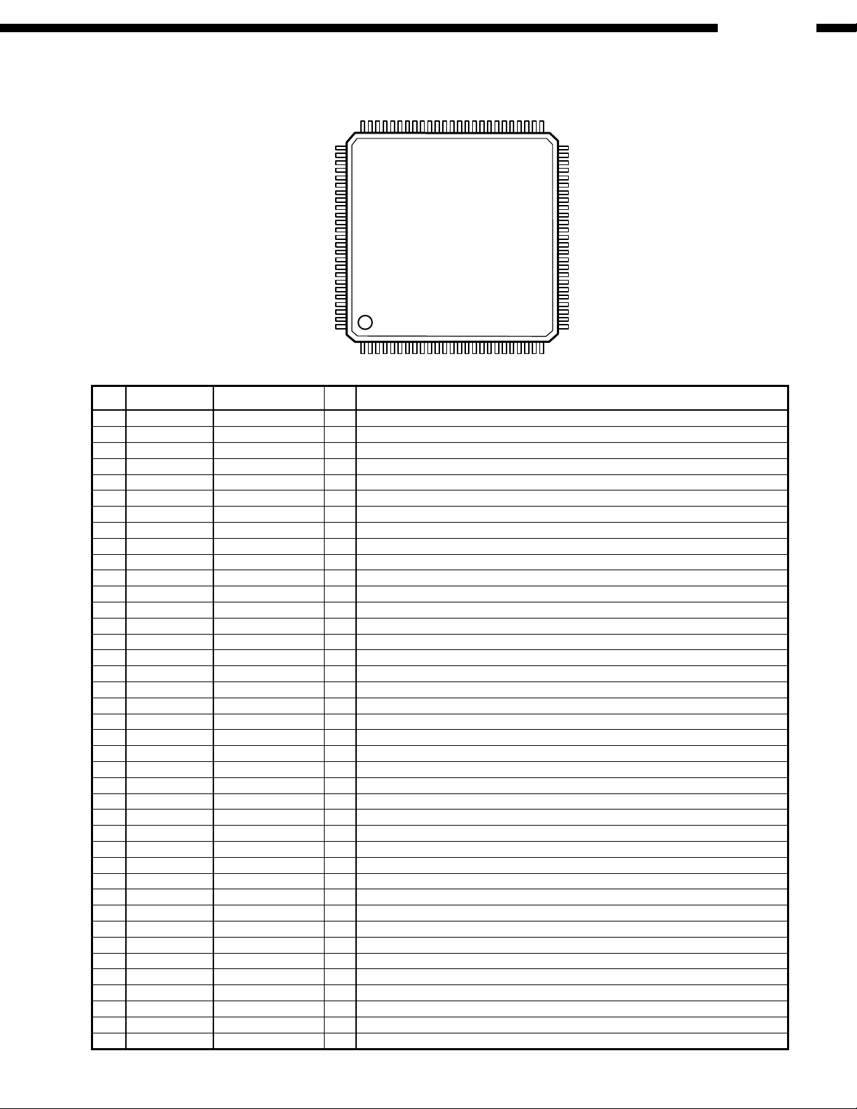
8. SEMICONDUCTORS
IC's
MN101C35DCA (IC601)
76
75
DVM-4800
51
50
100
1
MN101C35DCA Terminal Function
Pin
No.
10 OSC1 XO I Clock
11 VSS GND GND
12 XI GND I Not used
13 XO NC O Not used
14 MMOD GND I Memory mode
15 VREF- GND I A/D reference L
16 PA0 KEYIN0 I A/D key input
17 PA1 KEYIN1 I A/D key input
18 PA2 KEYIN2 I A/D key input
19 PA3 SWOP I Tray open detect, L: Open
20 PA4 SWCL I Tray close detect, L: Close
21 PA5 PA5 I Model set jumper 1
22 PA6 PA6 I Model set jumper 2
23 PA7 PA7 I Model set jumper 3
24 VREF+ 5V I A/D reference H
25 P07 POWERMUT O Power mute, H: Mute
26 P27 /RST I Reset
27 P10 SWDN I Chucking down detect, L: Down
28 P11 SWUP I Chucking up detect, L: Up
29 P12 OPEN O Tray open, H: Open
30 P13 CLOSE O Tray close, H: Close
31 P14 ROULETTE-L O Roulette left-turn, H: Left-turn
32 P15 ROULETTE-R O Roulette right turn, H: Right turn
33 P20 (IRQ0) REM I Remote-control input
34 P21 VSYNC I V-Sync (IRQ)
35 P22 W.REMIN I Wired remote-control input
36 P23 RFF I RFF
37 P24 R.SENS I Roulette sensor, H: detect slit
38 P25 D.SENS I Disc sensor, L: detect disc
39 P30 SDA O I2C SDA
40 P31 POWER-OFF O Main power control, L: On
Pin Name FunctionI/OSymbol
1 P00 ST-BY LED O ST-BY LED
2 P01 R-SPEED O Roulette rotation slow down, H: Down
3 P02 FL DRIVE O FL light off, L: Off
4 P03 CMD O Serial output
5 P04 STATUS I Serial input
6 P05 DSPCLK I Serial clock
7 P06 AUDIO ONLY LED O Audio Only LED
8VDD 5V +5V
9 OSC2 XI O Clock
26
25
27

DVM-4800
Pin
No.
41 P32 SCV O I2C SCL
42 P50 D.F.2.I I D.F.2 detect
43 P51 DEEMPH O Emphasis control
44 P52 RSTN O Reset output for D.F.1, L: Reset
45 P53 CKDV1 O Master clock switching sig.1
46 P54 CKDV2 O Master clock switching sig.2
47 P67 G17 O FL-DGT
48 P66 G16 O FL-DGT
49 P65 G15 O FL-DGT
50 P64 G14 O FL-DGT
51 P63 G13 O FL-DGT
52 P62 G12 O FL-DGT
53 P61 G11 O FL-DGT
54 P60 G10 O FL-DGT
55 P41 G9 O FL-DGT
56 P40 G8 O FL-DGT
57 P77 G7 O FL-DGT
58 P76 G6 O FL-DGT
59 P75 G5 O FL-DGT
60 P74 G4 O FL-DGT
61 P73 G3 O FL-DGT
62 P72 G2 O FL-DGT
63 P71 G1 O FL-DGT
64 P70 S1 O FL-SEG
65 P87 S2 O FL-SEG
66 P86 S3 O FL-SEG
67 P85 S4 O FL-SEG
68 P84 S5 O FL-SEG
69 P83 S6 O FL-SEG
70 P82 S7 O FL-SEG
71 P81 S8 O FL-SEG
72 P80 S8 O FL-SEG
73 P97 S10 O FL-SEG
74 P96 S11 O FL-SEG
75 P95 S12 O FL-SEG
76 P94 S13 O FL-SEG
77 P93 S14 O FL-SEG
78 P92 S15 O FL-SEG
79 P91 S16 O FL-SEG
80 P90 S17 O FL-SEG
81 PC2 S18 O FL-SEG
82 PC1 S19 O FL-SEG
83 PC0 S20 O FL-SEG
84 PB7 S21 O FL-SEG
85 PB6 S22 O FL-SEG
86 PB5 S23 O FL-SEG
87 PB4 S24 O FL-SEG
88 PB3 S25 O FL-SEG
89 PB2 S26 O FL-SEG
90 PB1 S27 O FL-SEG
91 PB0 S28 O FL-SEG
92 PD7 S29 O FL-SEG
93 PD6 S30 O FL-SEG
94 PD5 S31 O FL-SEG
95 PD4 S32 O FL-SEG
96 PD3 S33 O FL-SEG
97 PD2 S34 O FL-SEG
98 PD1 S35 O FL-SEG
99 PD0 S36 O FL-SEG
100 VPP -29V I -29V
Pin Name FunctionI/OSymbol
28
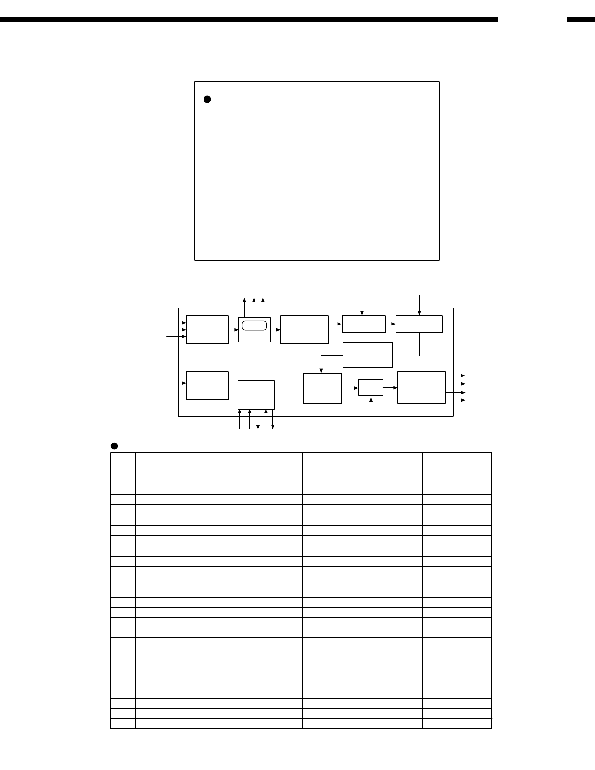
PMD200 (IC101)
DVM-4800
MODD
MODB
MODA
WCKO
BCKO
VCCS
GNDS
GNDG
VCCLQ
GNDQ
SMUTE
DOUT/DOL
VCCHQ
HMUTE
SPI/I2C
DEEMP
VCCS
GNDS
SS/HA2
MOSI/HA0
MISO/SDA
LRCI
BCKI
DIN
EXTAL
LRCI
BCKI
DOR
DIN
Input Data
Interface
Generator
NCNCNCNCGAIN
9998979695949392919089888786858483828180797877
100
1
2
3
4
5
6
7
8
9
10
11
12
13
14
15
16
17
18
19
20
21
22
23
24
25
26272829303132333435363738394041424344454647484950
HREQ
SCK/SCL
Timing
PINIT
NC
RESET
HDCD
HDCD
Detect
Control
Interface
VCCG
VCCP
ZERO
ZERO
PCAP
GAIN
GNDS
VCCS
GNDP
EXTAL
Interpolation
GNDQ
HDCDNCVCCHQ
GNDQ
GNDG
VCCLQ
VCCHQ
2xFs
Filter
Dither
Generator
VCCLQNCNC
GNDG
GNDG
GNDG
GNDG
NCNCNC
NCNCNC
VCCC
GNDC
SMUTE
Attenuator Deemphasls
Interpolation
Filter
Mute
GNDD
VCCD
GNDG
GNDG
NC
VCCA
GNDA
DEEMP
Output Data
Interface
GNDG
76
75
74
73
72
71
70
69
68
67
66
65
64
63
62
61
60
59
58
57
56
55
54
53
52
51
NC
GNDG
NC
NC
GNDA
VCCA
NC
NC
NC
NC
VCCLQ
GNDQ
GNDA
VCCA
NC
VCCHQ
NC
NC
NC
NC
GNDA
VCCA
NC
NC
NC
NC
DOL
DOR
WCKO
BCKO
PMD200 Terminal Function
Pin
No.
1
2
3
4
5
6
7
8
9
10
11
12
13
14
15
16
17
18
19
20
21
22
23
24
25
Signal Name
MODD
MODB
MODA
WCKO
LRCI
BCKO
BCKI
VCCS
GNDS
GNDG
VCCLQ
GNDQ
SMUTE
DOUT/DOL
VCCHQ
DOR
HMUTE
SPI/I2C
DEEMP
DIN
VCCS
GNDS
SS/HA2
MOSI/HA0
MISO/SDA
Pin
No.
27
28
29
30
31
32
33
34
35
36
37
38
39
40
41
42
43
44
45
46
47
48
49
50
SCK
MISO
MOSI
I2C/SPI
HREQ
Signal Name
SCK/SCL
HREQ
PINIT
RESET
NC
VCCP
PCAP
GNDP
EXTAL
VCCHQ
GNDQ
VCCLQ
GNDG
NC
NC
NC
VCCC
GNDC
NC
NC
NC
NC
VCCA
GNDA
NC
Pin
No.
51
52
53
54
55
56
57
58
59
60
61
62
63
64
65
66
67
68
69
70
71
72
73
74
75
HMUTE
Signal Name
NC26
NC
NC
NC
VCCA
GNDA
NC
NC
NC
NC
VCCHQ
NC
VCCA
GNDA
GNDQ
VCCLQ
NC
NC
NC
NC
VCCA
GNDA
NC
NC
GNDG
Pin
No.
76
77
78
79
80
81
82
83
84
85
86
87
88
89
90
91
92
93
94
95
96
97
98
99
100
Signal Name
GNDG
GNDG
GNDG
VCCD
GNDD
GNDG
GNDG
GNDG
GNDG
NC
NC
VCCLQ
GNDQ
VCCHQ
NC
HDCD
VCCS
GNDS
ZERO
VCCG
GAIN
NC
NC
NC
NC
29
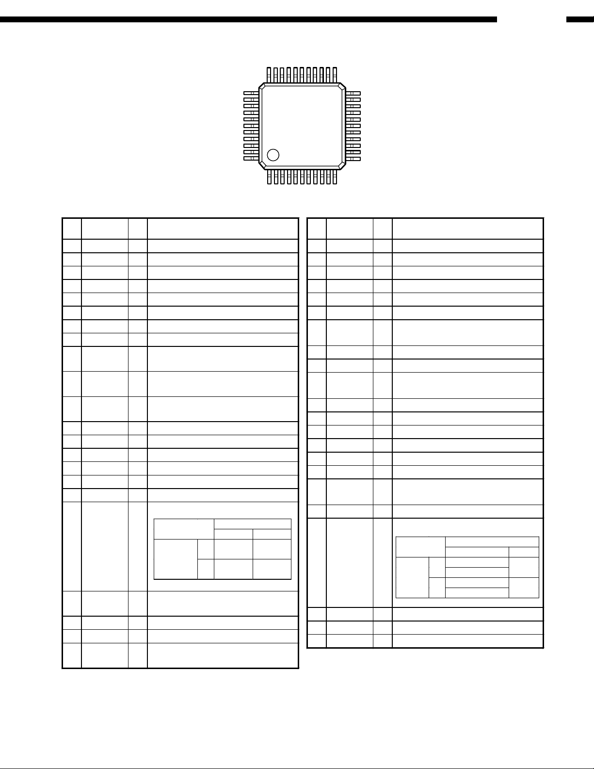
DVM-4800
DXP7001AF (IC201)
33
34
44
1
DXP7001AF Terminal Function
Pin
Pin Name I/O Description
No.
1 MDT Ip Microcomputer Interface Data
2 MCK Ip Microcomputer Interface Clock
3 MLEN Ip Microcomputer Interface Latch Enable
4 RSTN Ip Reset Terminal
5 DLRCK Ip Audio Serial Input Data L/R Clock
6 VSS
7 DBCK Ip Audio Serial Input Bit Clock
8 DDT Ip Audio Serial Input Data
9 TEST2N Ip
10 TEST3N Ip
11 TEST4N Ip
12 DFBCK Ip Lambda-processor Input Bit Clock
13 DFWCK Ip Lambda-processor Input Word Clock
14 DOL Ip Lambda-processor Input Data L-channel
15 DOR Ip Lambda-processor Input Data R-channel
16 LMOD Ip Lambda-processor Operation Mode Set
17 OMOD1 Ip Output Mode Setting Terminal 1
18 OMOD2 Ip
19 INVIN Ip
20 BCKO O Lambda-processor Output Bit Clock
21 WCKO O Lambda-processor Output Word Clock
22 WCKO2 O
Ground Terminal
−
Test Setting Terminal 2 (Alpha-processor 1
Output shifts 12-bit.)
Test Setting Terminal 3 (Alpha-processor 2
Output stops.)
Test Setting Terminal 4 (Lambda-processor
Output stops.)
Output Mode Setting Terminal 2
OMOD1
LH
18bit
L
H
Alternate
20bit
Parallel
OMOD2
Lambda-processor Input Reversed
Polarity Terminal
Lambda-processor Output Word Clock 2
(for Canceling OFFSET on 1DAC
24bit
Alternate
24bit
Parallel
23
22
12
11
Pin
Pin Name I/O Description
No.
23−P24L O−/Lambda-processor Lch 24th bit Output *1, *2
24−P23L O−/Lambda-processor Lch 23rd bit Output *1, *2
25−P22L O−/Lambda-processor Lch 22nd bit Output *1, *2
26−P21L O−/Lambda-processor Lch 21st bit Output *1
27−P20L O−/Lambda-processor Lch 20th bit Output *1
28 VDD
29 SO2L/P19L O
30 SO1L O Lambda-processor Lch(+) Output
31 SO1R O Lambda-processor Rch(+) Output
32 SO2R/P19R O
33−P20R O−/Lambda-processor Rch 20th bit Output *1
34−P21R O−/Lambda-processor Rch 21st bit Output *1, *2
35−P22R O−/Lambda-processor Rch 22nd bit Output *1, *2
36−P23R O−/Lambda-processor Rch 23rd bit Output *1, *2
37−P24R O−/Lambda-processor Rch 24th bit Output *1, *2
38 TEST1N Ip Test Terminal 1 (Alpha-processor 1 stops)
39 CKSLN Ip System Clock Select (384fs system /
40 CKDV1 Ip System Clock Divider Select Terminal 1
41 CKDV2 Ip
42 XTI I X-TAL Oscillator Input Terminal
43 XTO O X-TAL Oscillator Output Terminal
44 CKO O Clock Output Terminal
Power Supply Terminal
−
Lambda-processor Lch(−) Output /19
Output *1
Lambda-processor Rch(−) Output/19
Output *1
256fs system)
System Clock Divider Select Terminal 2
CKDV1
LH
192fs (CKSLN=H)
L
CKDV2
256fs (CKSLN=H)
192fs (CKSLN=H)
H
256fs (CKSLN=H)
th
th
768fs
384fs
bit
bit
(Ip = Input Terminal with pull-up)
*1: Outputted on OMOD1=L (18-bit Alternate Output or 20
-
bit Parallel Output)
*2: Internal Signal is outputted on OMOD1=H (24-bit Alternate Output or 24
or TEST4N is set to L.
-
bit Parallel Output) and one of TEST1N, TEST2N, TEST3N
30
 Loading...