

Denon DVM-1805 Service Manual
SERVICE MANUAL
For U.S.A & Canada model
MODEL
DVD VIDEO AUTO CHANGER
DVM-1805
Some illustrations using in this service manual are slightly different from the actual set.
16-11, YUSHIMA 3-CHOME, BUNKYOU-KU, TOKYO 113-0034 JAPAN
Telephone: 03 (3837) 5321
X0158 NC 0209

TABLE OF CONTENTS
SPECIFICATIONS . . . . . . . . . . . . . . . . . . . . . . . . . . . . . . . . . . . . . . . . . . . . . . . . . . . . . . . . . . . . . . . . . . . . . . . . . 3
LASER BEAM SAFETY PRECAUTIONS . . . . . . . . . . . . . . . . . . . . . . . . . . . . . . . . . . . . . . . . . . . . . . . . . . . . . . . 4
IMPORTANT SAFETY PRECAUTIONS . . . . . . . . . . . . . . . . . . . . . . . . . . . . . . . . . . . . . . . . . . . . . . . . . . . . . . . . 5
STANDARD NOTES FOR SERVICING . . . . . . . . . . . . . . . . . . . . . . . . . . . . . . . . . . . . . . . . . . . . . . . . . . . . . . . . 7
CABINET DISASSEMBLY INSTRUCTIONS . . . . . . . . . . . . . . . . . . . . . . . . . . . . . . . . . . . . . . . . . . . . . . . . . . . . 10
TROUBLESHOOTING. . . . . . . . . . . . . . . . . . . . . . . . . . . . . . . . . . . . . . . . . . . . . . . . . . . . . . . . . . . . . . . . . . . . . 14
BLOCK DIAGRAMS. . . . . . . . . . . . . . . . . . . . . . . . . . . . . . . . . . . . . . . . . . . . . . . . . . . . . . . . . . . . . . . . . . . . . . . 22
SCHEMATIC DIAGRAMS / CBA’S AND TEST POINTS . . . . . . . . . . . . . . . . . . . . . . . . . . . . . . . . . . . . . . . . . . . 30
WAVEFORMS . . . . . . . . . . . . . . . . . . . . . . . . . . . . . . . . . . . . . . . . . . . . . . . . . . . . . . . . . . . . . . . . . . . . . . . . . . . 32
WIRING DIAGRAMS . . . . . . . . . . . . . . . . . . . . . . . . . . . . . . . . . . . . . . . . . . . . . . . . . . . . . . . . . . . . . . . . . . . . . . 33
FIRMWARE RENEWAL MODE . . . . . . . . . . . . . . . . . . . . . . . . . . . . . . . . . . . . . . . . . . . . . . . . . . . . . . . . . . . . . . 34
LEAD IDENTIFICATIONS . . . . . . . . . . . . . . . . . . . . . . . . . . . . . . . . . . . . . . . . . . . . . . . . . . . . . . . . . . . . . . . . . . 36
EXPLODED VIEWS. . . . . . . . . . . . . . . . . . . . . . . . . . . . . . . . . . . . . . . . . . . . . . . . . . . . . . . . . . . . . . . . . . . . . . . 47
PARTS LIST . . . . . . . . . . . . . . . . . . . . . . . . . . . . . . . . . . . . . . . . . . . . . . . . . . . . . . . . . . . . . . . . . . . . . . . . . . . . 50
Manufactured under license from Dolby Laboratories. "Dolby"
and the double-D symbol are trademarks of Dolby Laboratories.
"DTS" and "DTS Digital Out" are trademarks of Digital Theater Systems Inc.

SPECIFICATIONS
ITEM CONDITIONS UNIT NOMINAL LIMIT
1. Video Output 75 ohm load Vpp 1.0
2. Optical Digital Out dBm -18
3. Audio (PCM)
3-1. Output Level 1kHz 0dB Vrms 2.0
3-2. S/N dB 110
3-3. Freq. Response
DVD fs=48kHz 20~22kHz dB ± 2
CD fs=44.1kHz 20~20 kHz dB ± 2
3-4. THD+N 1 kHz 0dB % 0.005
NOTES:
1. All Items are measured without pre-emphasis unless otherwise specified.
2. Power supply : AC120 V 60 Hz
3. Load imp. : 100 K ohm
4. Room ambient : +25
°
C
- 3 -
D
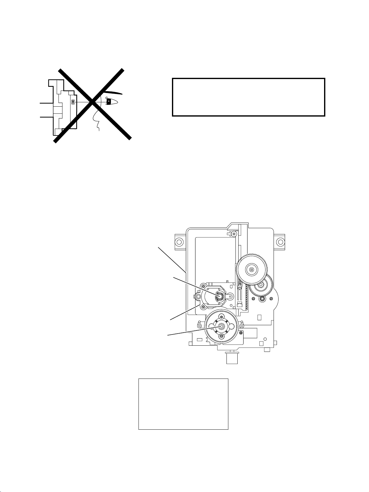
LASER BEAM SAFETY PRECAUTIONS
This DVD player uses a pickup that emits a laser beam.
Do not look directly at the laser beam coming
from the pickup or allow it to strike against
your skin.
The laser beam is emitted from the location shown in the figure. When checking the laser diode, be sure to keep
your eyes at least 30cm away from the pickup lens when the diode is turned on. Do not look directly at the laser
beam.
Caution: Use of controls and adjustments, or doing procedures other than those specified herein, may result in
hazardous radiation exposure.
rive Mecha Assembly
Laser Beam Radiation
Laser Pickup
Turntable
CAUTION
LASER RADIATION
WHEN OPEN. DO NOT
STARE INTO BEAM.
Location: Inside Top of DVD mechanism.
- 4 -

IMPORTANT SAFETY PRECAUTIONS
Product Safety Notice
Some electrical and mechanical parts have special
safety-related characteristics which are often not evident from visual inspection, nor can the protection
they give necessarily be obtained by replacing them
with components rated for higher voltage, wattage,
etc. Parts that have special safety characteristics are
identified by a # on schematics and in parts lists. Use
of a substitute replacement that does not have the
same safety characteristics as the recommended
replacement part might create shock, fire, and/or other
hazards. The Product’s Safety is under review continuously and new instructions are issued whenever
appropriate. Prior to shipment from the factory, our
products are carefully inspected to confirm with the
recognized product safety and electrical codes of the
countries in which they are to be sold. However, in
order to maintain such compliance, it is equally important to implement the following precautions when a set
is being serviced.
Precautions during Servicing
A. Parts identified by the # symbol are critical for
safety. Replace only with part number specified.
B. In addition to safety, other parts and assemblies
are specified for conformance with regulations
applying to spurious radiation. These must also be
replaced only with specified replacements.
Examples: RF converters, RF cables, noise blocking capacitors, and noise blocking filters, etc.
C. Use specified internal wiring. Note especially:
1)Wires covered with PVC tubing
2)Double insulated wires
3)High voltage leads
D. Use specified insulating materials for hazardous
live parts. Note especially:
1)Insulation tape
2)PVC tubing
3)Spacers
4)Insulators for transistors
E. When replacing AC primary side components
(transformers, power cord, etc.), wrap ends of
wires securely about the terminals before soldering.
F. Observe that the wires do not contact heat produc-
ing parts (heatsinks, oxide metal film resistors, fusible resistors, etc.).
G. Check that replaced wires do not contact sharp
edges or pointed parts.
H. When a power cord has been replaced, check that
5 - 6 kg of force in any direction will not loosen it.
I. Also check areas surrounding repaired locations.
J. Be careful that foreign objects (screws, solder
droplets, etc.) do not remain inside the set.
K. Crimp type wire connector
The power transformer uses crimp type connectors
which connect the power cord and the primary side
of the transformer. When replacing the transformer,
follow these steps carefully and precisely to prevent shock hazards.
Replacement procedure
1)Remove the old connector by cutting the wires at a
point close to the connector.
Important: Do not re-use a connector. (Discard it.)
2)Strip about 15 mm of the insulation from the ends
of the wires. If the wires are stranded, twist the
strands to avoid frayed conductors.
3)Align the lengths of the wires to be connected.
Insert the wires fully into the connector.
4)Use a crimping tool to crimp the metal sleeve at its
center. Be sure to crimp fully to the complete closure of the tool.
L. When connecting or disconnecting the internal con-
nectors, first, disconnect the AC plug from the AC
outlet.
- 5 -
r
e)
Safety Check after Servicing
Examine the area surrounding the repaired location for
damage or deterioration. Observe that screws, parts,
and wires have been returned to their original positions. Afterwards, do the following tests and confirm
the specified values to verify compliance with safety
standards.
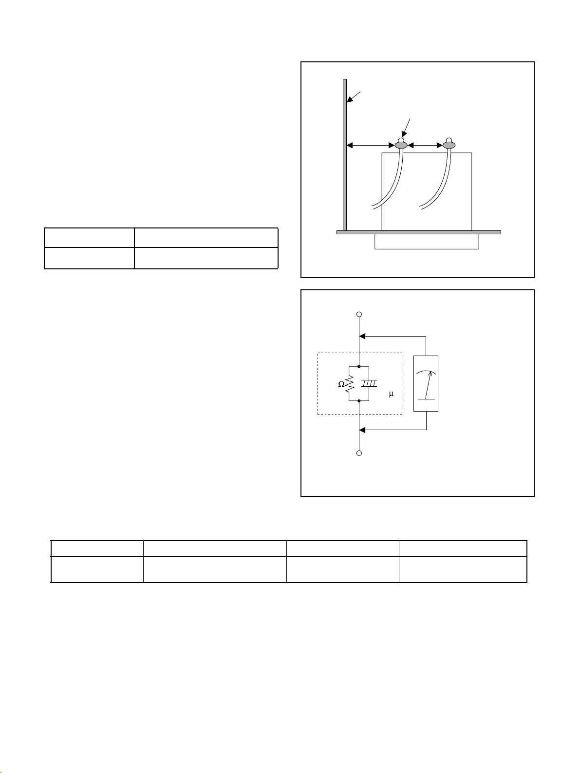
1. Clearance Distance
When replacing primary circuit components, confirm
specified clearance distance (d) and (d’) between soldered terminals, and between terminals and surrounding metallic parts. (See Fig. 1)
Table 1 : Ratings for selected area
AC Line Voltage Clearance Distance (d) (d’)
Chassis or Secondary Conducto
Primary Circuit Terminals
dd'
120 V
Note: This table is unofficial and for reference only.
Be sure to confirm the precise values.
2. Leakage Current Test
Confirm the specified (or lower) leakage current
between B (earth ground, power cord plug prongs)
and externally exposed accessible parts (RF terminals, antenna terminals, video and audio input and
output terminals, microphone jacks, earphone jacks,
etc.) is lower than or equal to the specified value in the
table below.
Measuring Method (Power ON) :
Insert load Z between B (earth ground, power cord
plug prongs) and exposed accessible parts. Use an
AC voltmeter to measure across the terminals of load
Z. See Fig. 2 and the following table.
Table 2: Leakage current ratings for selected areas
AC Line Voltage Load Z Leakage Current (i) Earth Ground (B) to:
120 V
3.2mm (0.126 inches)
≥
0.15µF CAP. & 1.5kΩ RES.
Connected in parallel
Exposed Accessible Part
Z
1.5k
i≤0.5mA Peak Exposed accessible parts
0.15 F
Earth Ground
B
Power Cord Plug Prongs
AC Voltmeter
(High Impedanc
Fig. 1
Fig. 2
Note: This table is unofficial and for reference only. Be sure to confirm the precise values.
- 6 -
STANDARD NOTES FOR SERVICING
O
P
P
Circuit Board Indications
a. The output pin of the 3 pin Regulator ICs is indi-
cated as shown.
Top View
ut
b. For other ICs, pin 1 and every fifth pin are indicated
as shown.
Input
In
in 1
c. The 1st pin of every male connector is indicated as
shown.
in 1
Bottom View
5
10
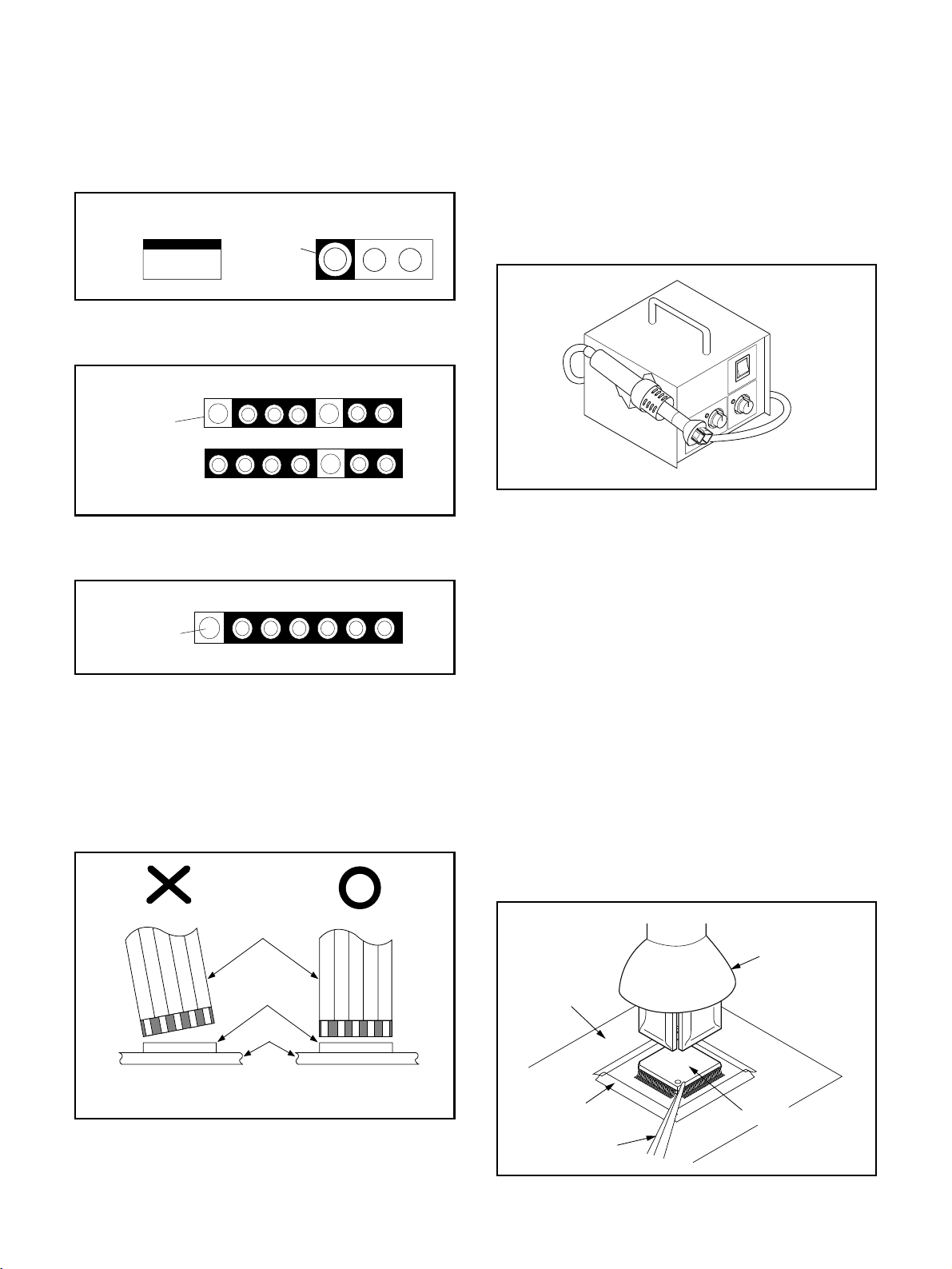
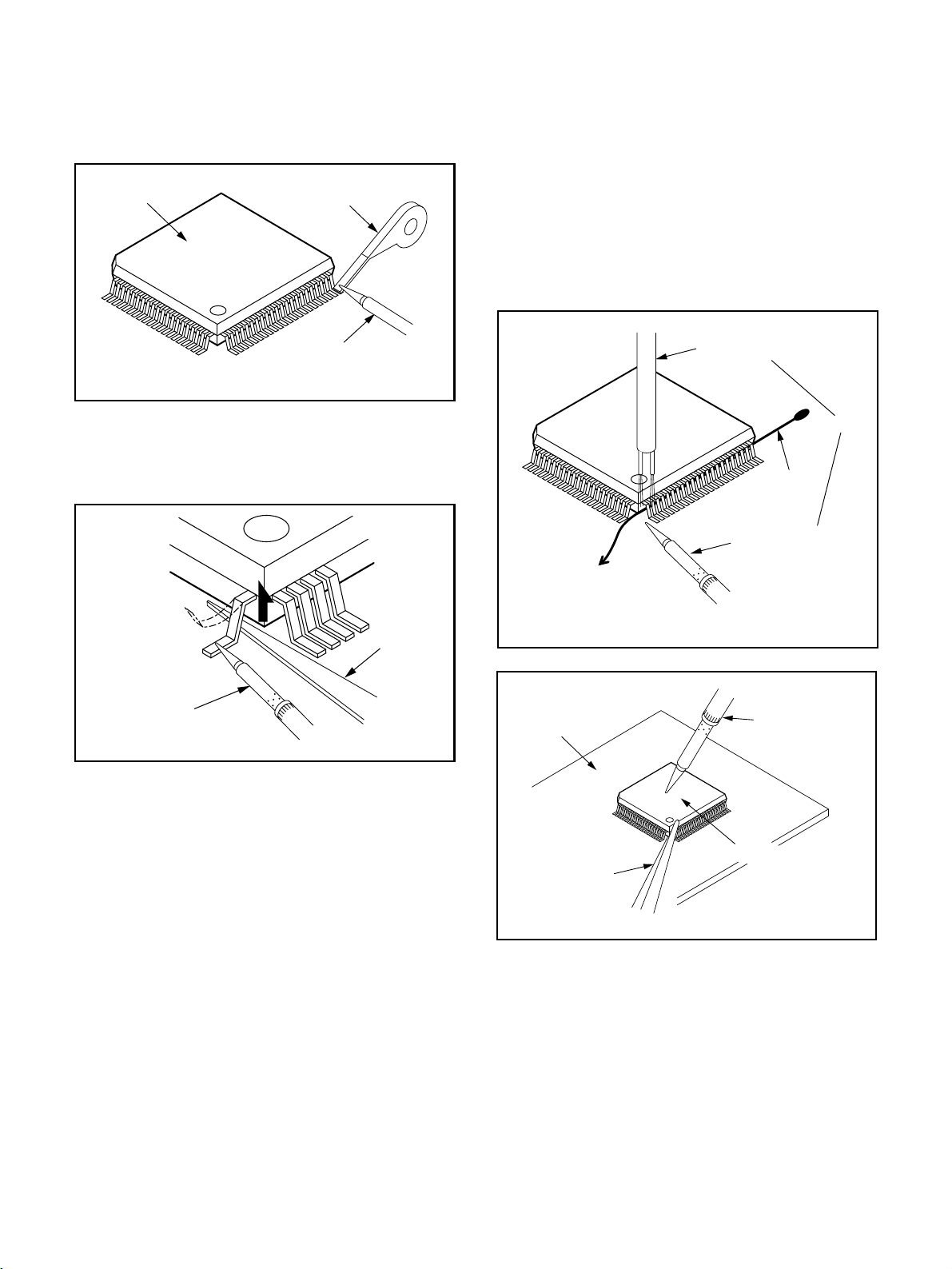
How to Remove / Install Flat Pack-IC
1. Removal
With Hot-Air Flat Pack-IC Desoldering Machine:.
(1) Prepare the hot-air flat pack-IC desoldering
machine, then apply hot air to the Flat Pack-IC
(about 5 to 6 seconds). (Fig. S-1-1)
Fig. S-1-1
(2) Remove the flat pack-IC with tweezers while apply-
ing the hot air.
(3) Bottom of the flat pack-IC is fixed with glue to the
CBA; when removing entire flat pack-IC, first apply
soldering iron to center of the flat pack-IC and heat
up. Then remove (glue will be melted). (Fig. S-1-6)
(1) Release the flat pack-IC from the CBA using twee-
zers. (Fig. S-1-6)
Instructions for Connectors
1. When you connect or disconnect the FFC (Flexible
Foil Connector) cable, be sure to first disconnect
the AC cord.
2. FFC (Flexible Foil Connector) cable should be
inserted parallel into the connector, not at an angle.
FFC Cable
Connector
CBA
* Be careful to avoid a short circuit.
Caution:
1. Do not supply hot air to the chip parts around the
flat pack-IC for over 6 seconds because damage to
the chip parts may occur. Put masking tape around
the flat pack-IC to protect other parts from damage.
(Fig. S-1-2)
2. The flat pack-IC on the CBA is affixed with glue, so
be careful not to break or damage the foil of each
pin or the solder lands under the IC when removing
it.
Hot-air
Flat Pack-IC
Desoldering
CBA
Masking
Tape
Tweezers
Machine
Flat Pack-IC
Fig. S-1-2
- 7 -
With Soldering Iron:
F
F
S
rp
or
n
(1) Using desoldering braid, remove the solder from all
pins of the flat pack-IC. When you use solder flux
which is applied to all pins of the flat pack-IC, you
can remove it easily. (Fig. S-1-3)
lat Pack-IC
Desoldering Braid
(4) Bottom of the flat pack-IC is fixed with glue to the
CBA; when removing entire flat pack-IC, first apply
soldering iron to center of the flat pack-IC and heat
up. Then remove (glue will be melted). (Fig. S-1-6)
(5) Release the flat pack-IC from the CBA using twee-
zers. (Fig. S-1-6)
Note:
When using a soldering iron, care must be taken
to ensure that the flat pack-IC is not being held by
glue. When the flat pack-IC is removed from the
CBA, handle it gently because it may be damaged
if force is applied.
Soldering Iron
Hot Air Blower
Fig. S-1-3
(2) Lift each lead of the flat pack-IC upward one by
one, using a sharp pin or wire to which solder will
not adhere (iron wire). When heating the pins, use
a fine tip soldering iron or a hot air desoldering
Iron Wire
machine. (Fig. S-1-4)
Soldering Iron
To Solid
Mounting Point
Fig. S-1-5
Sha
Pin
ine Tip
oldering Iron
CBA
Fine Tip
Soldering Iro
Fig. S-1-4
(3) Bottom of the flat pack-IC is fixed with glue to the
CBA; when removing entire flat pack-IC, first apply
soldering iron to center of the flat pack-IC and heat
up. Then remove (glue will be melted). (Fig. S-1-6)
(4) Release the flat pack-IC from the CBA using twee-
zers. (Fig. S-1-6)
Tweezers
Flat Pack-IC
With Iron Wire:
(1) Using desoldering braid, remove the solder from all
Fig. S-1-6
pins of the flat pack-IC. When you use solder flux
which is applied to all pins of the flat pack-IC, you
can remove it easily. (Fig. S-1-3)
(2) Affix the wire to a workbench or solid mounting
point, as shown in Fig. S-1-5.
(3) While heating the pins using a fine tip soldering
iron or hot air blower, pull up the wire as the solder
melts so as to lift the IC leads from the CBA contact
pads as shown in Fig. S-1-5
- 8 -
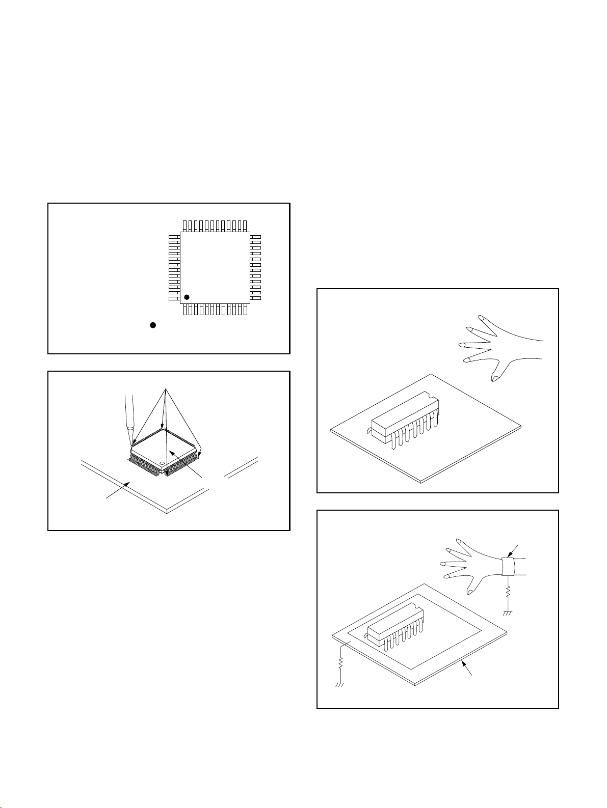
2. Installation
P
i
d
(1) Using desoldering braid, remove the solder from
the foil of each pin of the flat pack-IC on the CBA
so you can install a replacement flat pack-IC more
easily.
(2) The “I” mark on the flat pack-IC indicates pin 1.
(See Fig. S-1-7.) Be sure this mark matches the 1
on the PCB when positioning for installation. Then
presolder the four corners of the flat pack-IC. (See
Fig. S-1-8.)
(3) Solder all pins of the flat pack-IC. Be sure that none
of the pins have solder bridges.
Example :
in 1 of the Flat Pack-IC
s indicated by a " " mark.
Fig. S-1-7
Instructions for Handling
Semi-conductors
Electrostatic breakdown of the semi-conductors may
occur due to a potential difference caused by electrostatic charge during unpacking or repair work.
1. Ground for Human Body
Be sure to wear a grounding band (1MΩ) that is properly grounded to remove any static electricity that may
be charged on the body.
2. Ground for Workbench
(4) Be sure to place a conductive sheet or copper plate
with proper grounding (1MΩ) on the workbench or
other surface, where the semi-conductors are to be
placed. Because the static electricity charge on
clothing will not escape through the body grounding band, be careful to avoid contacting semi-conductors with your clothing.
< Incorrect >
CBA
Presolder
Flat Pack-IC
Fig. S-1-8
CBA
< Correct >
Grounding Ban
1MΩ
CBA
1MΩ
Conductive Sheet or
Copper Plate
- 9 -
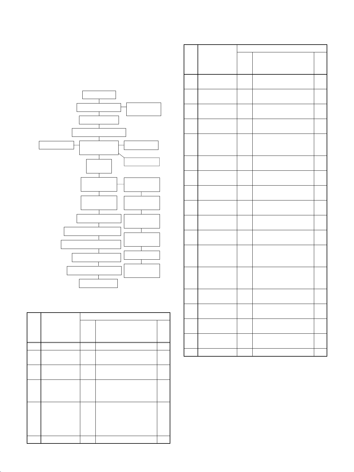
CABINET DISASSEMBLY INSTRUCTIONS
1. Disassembly Flowchart
This flowchart indicates the disassembly steps to gain
access to item(s) to be serviced. When reassembling,
follow the steps in reverse order. Bend, route, and
dress the cables as they were originally.
[1] Top Cover
[9] Power SW
CBA
[7] Relay CBA
[8] Sensor CBA
[12] Loading
Pulley
[13] Slide Tray
Gear (B)
[14] Slide Tray
Gear (A)
[15] Motor
Assembly
[16] Switch CBA
[17] Tray
Guide (R)
[6] Front CBA
[21] Progressive CBA Unit
[2] Front Assembly
[3] Bracket (Top)
[4] Stopper Bracket L, R
[5] Drive Mecha
Assembly
[10] Tray
Guide (L)
[11] Tray Guide
(R) Unit
[18] Power
Supply CBA
[19] Changer CBA
[20] PRO PCB(A) Shield
[22]
Shield Assembly
[23] DVD Main CBA Unit
[24] Rear Panel
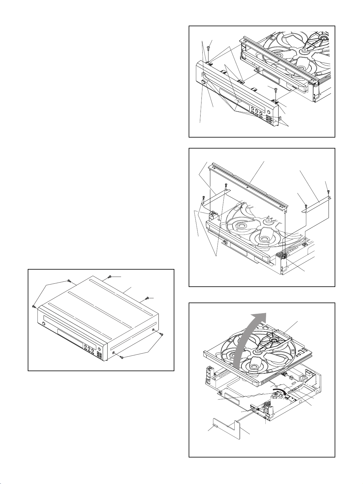
2. Disassembly Method
ID/
LOC.
No.
PART
Fig.
No.
[1] Top Cover D1 6(S-1) -
Front
[2]
[3]
Assembly
Bracket
(Top)
D2 2(S-2), *8(L-1) 1-1
D3 *2(L-2) -
Stopper
[4]
Bracket
D3 4(S-3) -
L, R
Drive Mecha
[5]
Assembly
D4,
D5
[6] Front CBA D4 *2(L-3), CN2002 -
REMOVAL
REMOVE/*UNHOOK/
UNLOCK/RELEASE/
UNPLUG/DESOLDER
CN101, CN3002
Note
2
2-1
2-2
3
4
ID/
LOC.
PART
No.
[7] Relay CBA D6
Sensor
[8]
CBA
Power SW
[9]
CBA
Tray
[10]
Guide (L)
Tray
[11]
Guide (R)
Unit
Loading
[12]
Pulley
Slide Tray
[13]
Gear (B)
Slide Tray
[14]
Gear (A)
Motor
[15]
Assembly
Switch
[16]
CBA
Tray
[17]
Guide (R)
Fig.
No.
D6 CN5101, 2(S-5) -
D7 CN2103, (S-6) -
D7 6(S-7) -
D7
D8 (S-9), Belt L -
D8 (S-10), *(P-1) -
D8 ---------- -
D8 (S-11) -
D8 *2(L-4) -
D8 ---------- -
REMOVAL
REMOVE/*UNHOOK/
UNLOCK/RELEASE/
UNPLUG/DESOLDER
2(S-4), CN5002,
CN5005
8(S-8), CN3004,
CN3006
Note
-
-
Power
[18]
Supply
D9 CN1002, 3(S-12) -
CBA
Changer
[19]
CBA
PRO PCB(A)
[20]
Shield
Progressive
[21]
CBA Unit
Shield
[22]
Assembly
DVD Main
[23]
CBA
6(S-13), 5(S-14),
D9
CN1601, CN1602,
CN1001, CN3001
D10 3(S-15) -
D10 CN1801 -
D10 ---------- -
D10 ---------- -
-
[24] Rear Panel D11 4(S-17) -
↓
(1)
↓
(2)
↓
(3)
↓
(4)
↓
(5)
(1): Identification (location) No. of parts in the figures
(2): Name of the part
(3): Figure Number for reference
(4): Identification of parts to be removed, unhooked,
unlocked, released, unplugged, unclamped, or
desoldered.
P=Spring, L=Locking Tab, S=Screw,
CN=Connector
- 10 -
*=Unhook, Unlock, Release, Unplug, or Desolder
e.g. 2(S-2) = two Screws (S-2),
2(L-2) = two Locking Tabs (L-2)
(5): Refer to “Reference Notes.”
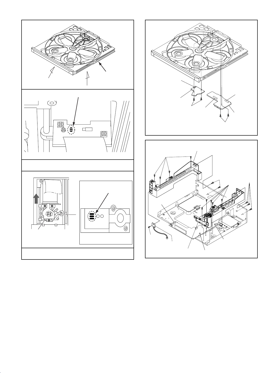
(L-1)
(S-2)
(B)
Reference Notes
CAUTION 1: Locking Tabs (L-1) are fragile. Be careful
not to break them.
1-1. To release eight Locking Tabs (L-1), first release
five Locking Tabs (A), and then three Locking
Tabs (B). (Fig. D2)
CAUTION 2: Electrostatic breakdown of the laser
diode in the optical system block may occur as a
potential difference caused by electrostatic charge
accumulated on cloth, human body etc, during
unpacking or repair work.
To avoid damage of pickup follow next procedures.
2-1. Slide out the pickup unit as shown in Fig. D5.
2-2. Short the three short lands of FPC cable with sol-
der before removing the FFC cable (CN101) from
it. If you disconnect the FFC cable (CN101), the
laser diode of pickup will be destroyed. (Fig. D5)
CAUTION 3: When reassembling, confirm the FFC
cable (CN101) is connected completely. Then remove
the solder from the three short lands of FPC cable.
(Fig. D5)
CAUTION 4: Before reinstalling, turn the Slide Tray
Gear (B) fully clockwise. (Fig. D4)
(L-1)
(L-1)
[2] Front Assembly
[4] Stopper Bracket L
(L-2)
(A)
(S-2)
(L-1)
(B)
[3] Bracket (Top)
[4] Stopper Bracket R
(S-3)
(L-1)
Fig. D2
(S-3)
(S-1)
(S-1)
[1] Top Cover
(S-1)
Fig. D1
(S-1)
(S-3)
Slide Tray
Gear (B)
CN2102
(L-3)
A
Turn
(L-3)
[6] Front CBA
(L-2)
Fig. D3
[5] Drive Mecha
Assembly
CN101
CN3002
- 11 -
Fig. D4
A
B
Drive Mecha
Assembly
CN5101
Slide
Short the three short lands by soldering
View for A
OR
Short the three short
lands by soldering
C
[8] Sensor CBA
(S-7)
CN2103
(S-5)
CN5005
[10] TrayGuide (L)
(S-4)
(S-7)
CN5002
[7] Relay
CBA
Fig. D6
(S-8)
(S-8)
Pickup Unit
View for B
View for C
Fig. D5
- 12 -
(S-6)
[9] Power SW CBA
[11] TrayGuide (R)Unit
CN3006
CN3004
Fig. D7
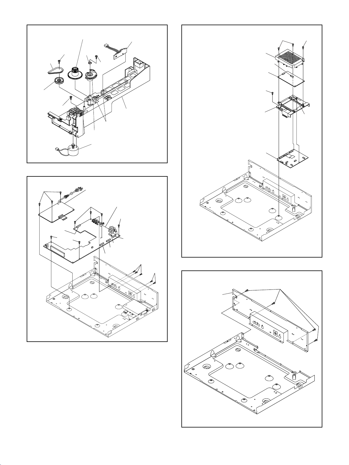
[14] Slide Tray Gear (A)
)
[16] Switch CBA
(S-15) (S-15)
Belt L
[12] Loading
Pulley
(S-11)
(S-12)
(S-9)
(P-1)
(S-10)
[17] Tray Guide (R
(L-4)
[13] Slide Tray Gear (B)
[15] Motor Assembly
[18] Power Supply CBA
(S-13)
[19] Changer CBA
(S-13)
Fig. D8
[20] PRO PCB(A) Shield
CN1801
[21] Progressive CBA Unit
(S-16)
[22] Shield
Assembly
(S-16)
[23] DVD Main CBA Unit
CN2100
(S-13)
CN1602
CN1001
CN3001
CN1601
Fig. D10
(S-14)
(S-14)
(S-17)
[24] Rear Panel
Fig. D9
Fig. D11
- 13 -
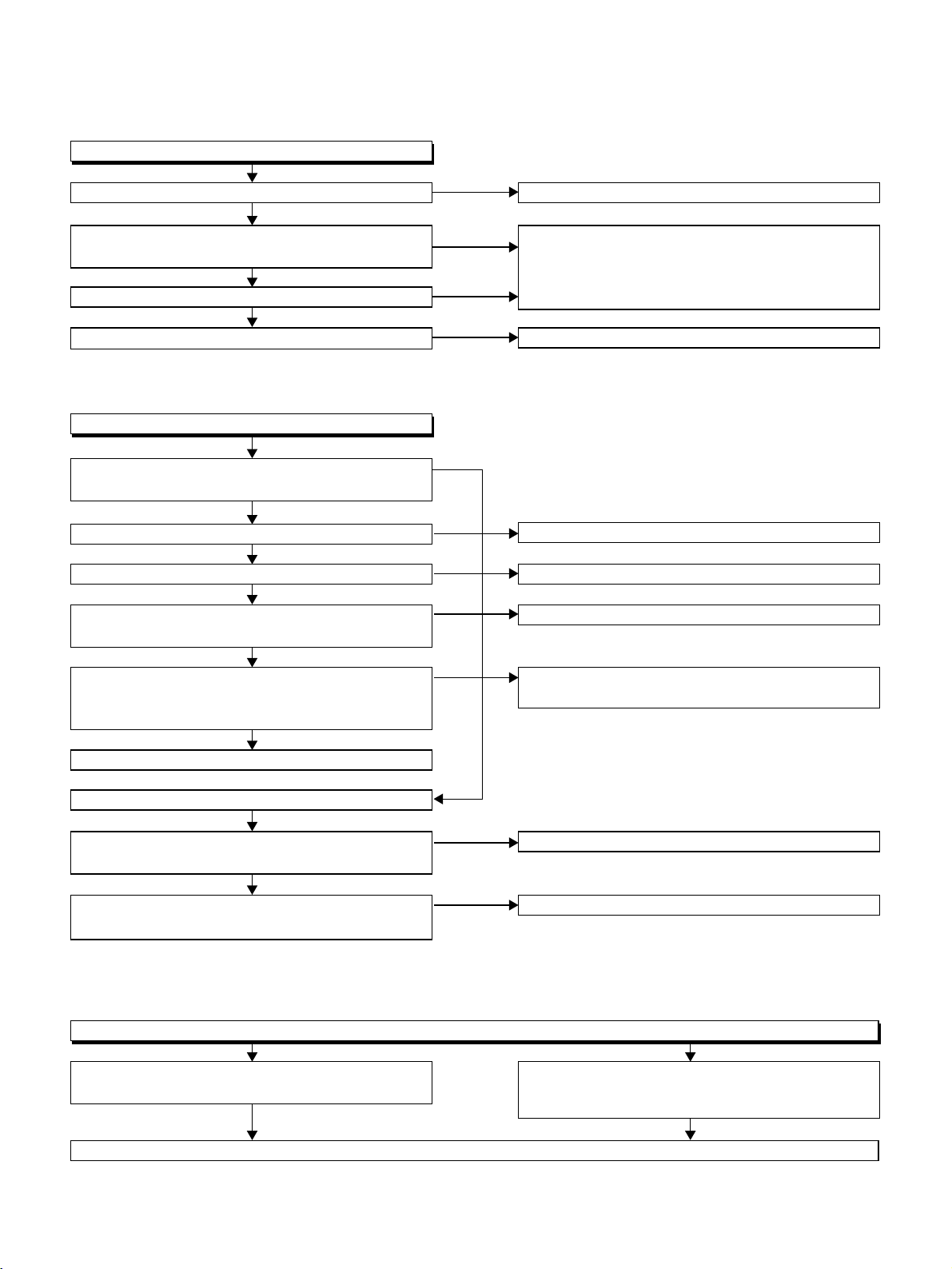
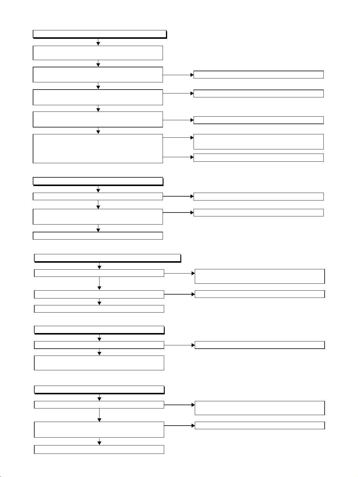
FLOW CHART NO.1
The power cannot be turned on.(1)
TROUBLESHOOTING
Is the fuse normal?
Yes
Is normal state restored when once unplugged
power cord is plugged again after several seconds?
Yes
Is the EV 5V line voltage normal?
Yes
Is the voltage of secondary side normal?
FLOW CHART NO.2
The power cannot be turned on.(2)
Does the change from STANDBY LED indicate
turn-off?
Yes
Is the voltage of 3.3V supplied to Q2021?
Yes
Is the voltage of 5V supplied to pin(3) of IC2001?
Yes
Is the "H" signal inputted to the base of Q2021,
when the POWER button activated on the DVD?
Yes
Is the "H" signal inputted at base of Q2021,
when the POWER button activated on the remote
control unit?
Yes
Replace Q2021.
No
No
No
No
No
No
No
No
No
See FLOW CHART No.3 <The fuse blows out.>
Check if there is any leak or shor-circuit on the
primary circuit component?
(Q1001, Q1003,T1001, D1001, D1002, D1004,
D1005, D1011, C1003, C1005)
Check each rectifying circuit of secondary circuit.
Check the EV 3.3V line.
Check the IC2001.
Check the POWER button line.
Check the line between the remote control
receiver and Pin(26) of CN1001.
The STANDBY LED indicate is flashing after 0.5 sec.
Yes (below, confirmed operating at LED turn-off of 0.5 sec. interval.)
Are the "P-ON-H" pulse outputted from the
pin(20) of CN1001?
Yes
Is the P-CON switch circuit operated normally?
(Q1002, Q1005, Q1006, IC1002, D1036, D1046)
FLOW CHART NO.3
The fuse blows out.
Check the presence that the primary component
is leaking or short then service it if defective.
After servicing, replace the fuse.
No
No
Replace the DVD Main CBA Unit.
Check each component, and replace.
Check the presence that the rectifying diode or
circuit is shorted in each rectifying circuit of
secondary side then service it if defective.
- 14 -
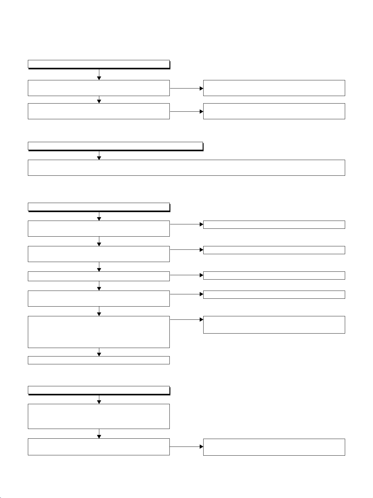
FLOW CHART NO.4
.
,
.
When the output voltage fluctuates.
Does the photo coupler circuit on the secondary
side operate normally?
Yes
Does the photo coupler circuit on the primary side
operate normally?
FLOW CHART NO.5
When buzz sound can be heard in the vicinity of the power circuit.
Check if there is any short-circuit on the rectifying diode and the circuit in each rectifying circuit of the secondary side
(D1003, D1008, D1009, D1013, D1016, D1030, IC1002, Q1002, Q1004, Q1007, Q1011, Q1014)
FLOW CHART NO.6
The fluorescent display tube does not light.
Is the voltage of 5V supplied to Pins(6, 24)
of IC2001?
Yes
Is the voltage of -24V supplied to Pin(15) of
IC2001?
Yes
Is there 500kHz oscillation to Pin(26) of IC2001?
Yes
Check the signal lines of FP-DIN, FP-DOUT,
FP-CLK, FP-STB of IC2001 and CN1001?
Yes
Are the filament voltage applied between (1, 2)
and (34, 35) of the fluorescent display tube?
Also negative voltage applied between these pins
and GND?
Yes
Replace the fluorescent display tube.
No
No
No
No
No
No
No
Check the circuit and replace the parts.
(IC1001, IC1006, D1048, D1015)
Check the circuit and replace the parts.
(IC1001, D1012, D1024)
Check the EV 5V line.
Check the -FL (-24V) line.
Check R2001, IC2001 and their periphery.
Check or replace IC2001 and DVD Main CBA unit
Check or replace the power circuit, D1016, D1017
and R1042, and their periphery.
FLOW CHART NO.7
The key operation is not functioning.
Are the contact point and the installation state of the
key switches(SW2201-2206, 2208-2212, 2214,
2215) normal?
Yes
Is the control voltage normally supplied to
Pins(3, 4, 7, 8, 9, 10, 11, 12, 13) of IC2001?
No
- 15 -
Check the key switches (
2214, 2215
), and their periphery circuit.
SW2201-2206, 2208-2212
FLOW CHART NO.8
No operation is possible from the remote control unit.
Operation is possible from the DVD, but no
operation is possible from the remote control unit.
Yes
Is no operation possible if replacing the remote
control unit?
Yes
Is 5V voltage supplied to Pin(3) terminal of infrared
remote control receiver?
Yes
Is the "L" pulse sent out from Pin(1) terminal of the
receiver when the infrared remote control is activated?
Yes
Is the "L" pulse signal supplied to Pin(26) of
CN1001 from Pin(1) of receiver? (Be operated by
SEARCH(-), SEARCH(+), PLAY, STILL/PAUSE,
STOP, POWER and OPEN/CLOSE button.)
FLOW CHART NO.9
PON 12V is not outputted.
No
No
No
No
Yes
Original remote control unit is poor.
Check EV 5V line.
Replace the infrared remote control receiver.
Check the line between the infrared remote control
receiver and Pin(26) of CN1001.
Replace DVD Main CBA unit.
Is PON12V voltage supplied to the collector of Q1002?
Yes
Does the P-ON switch circuit operate normally?
(Q1005, Q1006, D1036, etc.)
Yes
Replace Q1002.
FLOW CHART NO.10
PON 5V is not outputted. (PON 12V is outputted normally.)
Is 5V voltage supplied to the collector of Q1004?
Yes
Is the "H" pulse inputted into the base of Q1004?
Yes
Replace Q1004.
FLOW CHART NO.11
-FL is not outputted.
Is -24V voltage supplied to the anode of D1003?
Yes
Check if there is any leak or short-circuit on the
loaded circuit.
No
No
No
No
No
Check D1009, C1012 and the periphery circuit.
Check each component, and replace.
Check D1030, D1048, C1035, C1048 and the
periphery circuit.
Check D1046 and the periphery circuit.
Check D1003 and periphery circuit.
FLOW CHART NO.12
PON 3.3V is not outputted.
Is 3.3V voltage supplied to the emitter of Q1011?
Yes
Does the P-CON switch circuit operate normally?
(Q1005, Q1006, etc.)
Yes
Replace Q1011.
No
No
Check D1008, D1015, C1007, C1038 and the
periphery circuit.
Check each component, and replace.
- 16 -
 Loading...