

Page 1
CD RECORDER
CDR-WI500
OPERATING INSTRUCTIONS
MODE D’EMPLOI
INSTRUCCIONES DE OPERACION
FOR ENGLISH READERS
POUR LES LECTEURS FRANCAIS
PARA LECTORES DE ESPAtiOL
PAGE
PAGE 36-PAGE 66
PAGINA 67 - PAGINA 97
5-PAGE 35
Page 2
CAUTION:
TO REDUCE THE RISK OF ELECTRIC SHOCK, DO NOT REMOVE COVER
(OR BACK). NO USER SERVICEABLE PARTS INSIDE. REFER SERVICING
TO QUALIFIED SERVICE PERSONNEL.
The lightning flash with arrowhead symbol, withln an equilateral triangle, is intended to alert the
user to the presence of uninsulated “dangerous voltage” within the product’s enclosure that may
A
A
WARNING:
be of sufficient magnitude to constitute a risk of electric shock to persons.
The exclamation point wlthin an equilateral triangle IS intended to alert the user to the presence of
important operating and maintenance (servicing) instructions In the literature accompanying the
appliance.
TO REDUCE THE RISK OF FIRE OR ELECTRIC SHOCK, DO NOT EXPOSE
THIS APPLIANCE TO RAIN OR MOISTURE.
LABELS
CAUTION:
USE OF CONTROLS OR ADJUSTMENTS OR
PERFORMANCE OF PROCEDURES OTHER THAN THOSE
SPECIFIED HEREIN MAY RESULT IN HAZARDOUS
RADIATION EXPOSURE.
THE COMPACT DISC PLAYER SHOULD NOT BE ADJUSTED
OR REPAIRED BY ANYONE EXCEPT PROPERLY QUALIFIED
SERVICE PERSONNEL.
(for US A model only)
THIS PRODUCT COMPLIES WITH DHHS RULES 21 CFR
SUBCHAPTER J APPLICABLE AT DATE OF MANUFACTURE
This device complles with Part 15 of the FCC Rules.
Operation IS subject to the followlng two condltlons :
(1) This device may not cause harmful interference,
and (2) this device must accept any Interference
received. Including Interference that may cause
undesired operation
This Class B dIgItal apparatus meets all requirements
of the Canadian Interference-Causing Equipment
Regulations.
Cet appareil num&que de la classe 6 respecte toutes
les exlgences du Reglement sur le materiel brouilleur
du Canada.
CERTIFICATION
l FOR U.S.A. & CANADA MODEL ONLY
CAUTION
TO PREVENT ELECTRIC SHOCK, MATCH WIDE
BLADE OF PLUG TO WIDE SLOT, FULLY
INSERT
l POUR LES MODELES AMERICAINS ET
CANADIENS UNIQUEMENT
ATTENTION
I
PouR
~VITER
INTERODUIRE LA LAME LA PLUS LARGE DE LA
LES ctiocs
FICHE DANS LA BORNE CORRESPONDANTE DE
LA PRISE ET POUSSER JUSQU’ AU FOND.
ELECTRIQUES,
SAFETY INSTRUCTIONS
1.
Read Instructions - All the safety and operating
instructions should be read before the appliance
is operated.
2.
Retain Instructions - The safety and operating
instructions should be retalned for future
reference.
3.
Heed Warning - All warnings on the appliance
and in the operating Instructions should be
adhered to.
4. FoIlowIng lnstructlons - All operating and use
instructions should be followed.
5. Water and Moisture - The appliance should not
be used near water - for example, near a
bathtub, washbbowl, kitchen sink, laundry tub, In
a wet basement, or near a swlmmlng pool, and
the like.
6. Carts and Stands -The appliance should be used
only with a cart or stand that IS recommended by
the manufacturer.
An appliance and cart
6A
combinatron should be
moved with care.
Quick stops, excessive
force, and uneven
surfaces may cause
the appliance and cart
combination to overturn.
7. Wall or Ceiling Mounting - The applrance should
be mounted to a wall or ceiling only as
recommended by the manufacturer
8. Ventllatlon -The appliance should be situated so
that its location or position does not interfere
with its proper ventilation. For example, the
appliance should not be situated on a bed, sofa,
rug, or similar surface that may block the
ventilation openings; or, placed In a built-in
installation, such as a bookcase or cabinet that
may Impede the flow of air through the
ventilation openings.
9.
Heat - The appliance should be situated away
from heat sources such as radiators, heat
registers, stoves, or other appliances (including
amplifiers) that produce heat.
10
Power Sources - The appliance should be
connected to a power supply only of the type
described in the operating lnstructlons or as
marked on the appliance.
11 Grounding or Polarization - Precautions should be
taken so that the grounding or polarization means
of an appliance IS not defeated.
12. Power-Cord Protection - Power-supply cords
should be routed so that they are not likely to be
walked on or plnched by items placed upon or
against them, paying particular attention to cords
at plugs, convenience receptacles, and the point
where they exit from the appliance.
14. Cleaning - The appliance should be cleaned only
as recommended by the manufacturer.
15. Power Lines - An outdoor antenna should be
located away from power lines.
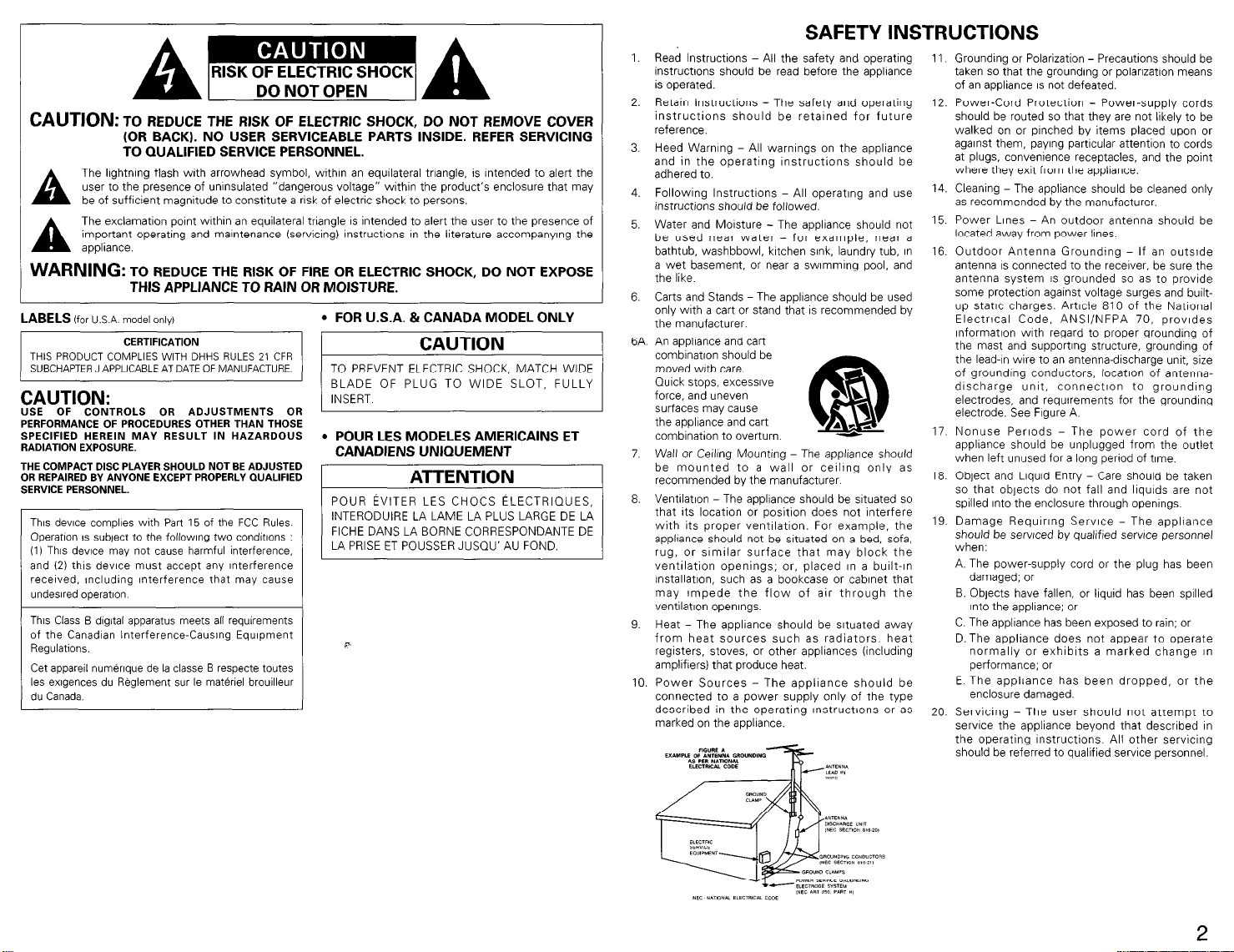
16. Outdoor Antenna Grounding - If an outslde
antenna IS connected to the receiver. be sure the
antenna system IS grounded so as to provide
some protectlon against voltage surges and builtup static charges. Article 810 of the Natlonal
Electrical Code, ANSl/NFPA 70, provides
InformatIon with regard to proper grounding of
the mast and supporting structure, grounding of
the lead-In wire to an antenna-discharge unit, size
of grounding conductors, locatlon of antennadischarge unit, connectlon to grounding
electrodes, and requirements for the grounding
electrode. See Figure A.
17. Nonuse Periods - The power cord of the
appliance should be unplugged from the outlet
when left unused for a long period of time.
18. Object and Liquid Entry - Care should be taken
so that objects do not fall and llqulds are not
spilled Into the enclosure through openings.
19. Damage Requlrlng Service - The appliance
should be serviced by qualified service personnel
when:
A. The power-supply cord or the plug has been
damaged; or
B. Objects have fallen, or liquid has been spilled
Into the appliance; or
C. The appliance has been exposed to rain; or
D.The appliance does not appear to operate
normally or exhibits a marked change In
performance; or
E The appliance has been dropped, or the
enclosure damaged.
20. Servicing - The user should not attempt to
service the appliance beyond that described In
the operating Instructions. All other servicing
should be referred to qualified service personnel.
2
Page 3
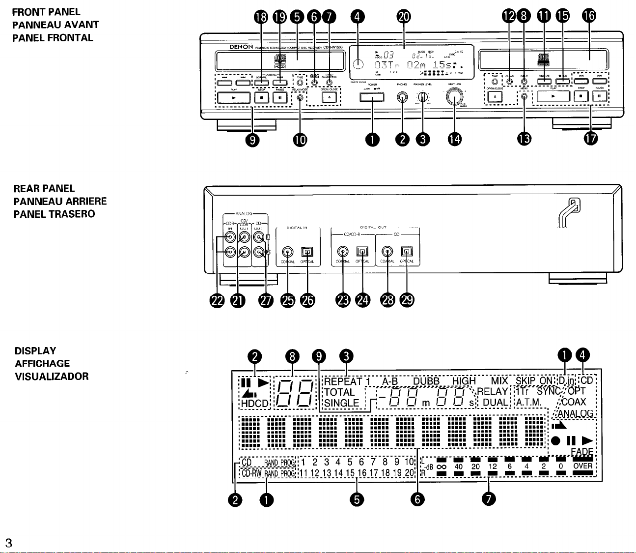
FRONT PANEL
PANNEAU AVANT
PANEL FRONTAL
REAR PANEL
PANNEAU ARRIERE
PANEL TRASERO
DISPLAY
AFFICHAGE
VISUALIZADOR
3
Page 4
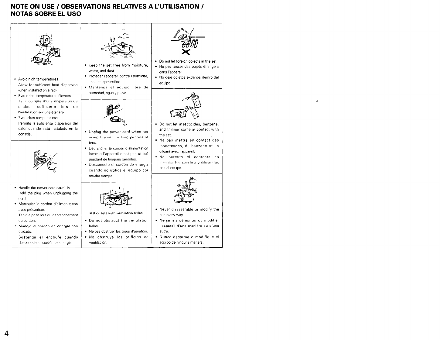
NOTE ON USE / OBSERVATIONS RELATIVES A WTILISATION /
NOTAS SOBRE EL US0
l
Do not let foreign objects I” the set
l
Ne ms lhsser des oblets Btranqers
dans I’appareil.
I’ ‘-
e objetos extratios dentro del
l
Do not let Insectndes. benzene.
and thinner come I” contact with
~ l
‘,“:‘,‘,‘; mettle en contact des
Insectlcldes, du benzene et “n
dlluant avec I’appare~l
l
No perrmta el contacto de
Insecticldas, gasollna y dlluyentes
l
AvoId high temperatures
Allow for sufflclent heat dispersion
when installed on a rack
l
Evlter des temp&atures &v&s
Tenlr compte d’une dispersvan de
chaleur suffisante lors de
I’1nstallat10n sur une &g&e
l
Ewe altas temperaturas.
PermIte la suflclente dlsperslOn del
calor cuando estd instalado en la
innlri
l
Keep the set free from mastwe.
water. and dust
l
Pr&ger I’apparell contre I’humldlt&
I’eau et lapousslere
l
Mantenga el equ~po llbre de
humedad, ag”a y polvo
l
Unplug the power cord when not
using the set for long perlods of
l
DBbrancher le cordon d’allmentatlon
lorsque i’apparw n’est pas utills&
pendant de longues perlodes
l
Desconecte el cord6n de energia
cuando no utlhce el equ,po por
mucho tlempo
l
Handle the power cord carefully
Hold the plug when unplugging the
cord.
l
Manlpuler ie cordon d’allmen-tation
avec precaution
Tenlr la prose lors du d&branchement
du cordon.
l
Manele el cordOn de energfa con
culdado
Sostenga el enchufe cuando
desconecte el cordbn de energia
4
l
* (For sets with ventllatlon holes1
l
Do not obstruct the ventllatlon
holes.
l
Ne pas obstruer les trws d’a&atlon
l
No obstruya 10s orlflcios de
Never disassemble or modify the
set I” any way
l
Ne jarwe d&nonter ou modifier
I’appareil d’une man16re ou d’une
autre.
l
Nunca desarme o modlflque el
VentllaclOn equlpo de nlnguna manera.
Page 5
IMPORTANT TO SAFETY
WARNING:
TO PREVENT FIRE OR SHOCK HAZARD, DO
NOT EXPOSE THIS APPLIANCE TO RAIN OR
MOISTURE.
CAUTION:
1. Handle the power supply cord carefully
Do not damage or deform the power supply cord If it IS
damaged or deformed, it may cause electric shock or malfunction
when used When removing from wall outlet, be sure to remo”e
by holding the plug attachment and not by pulling the cord
2. Do not open the top cover
In order to prevent electric shock, do not open the top cover
If problems occw, contact your DENON DEALER
3. Do not place anything inside
Do not place metal objects or spill llquld nslde the CD recorder
Electric shock or malfunction may result
Please, record and ‘eta,” the Model name and ser,al number of your
set shown on the rating label.
Model No. CDR.W1500 Serial No
Thank you for purchasing th,s DENON CD recorder. Please read the
operating ~nstiuct~ons thoroughly I” order to acquaint yourself with the
CD recorder and achieve maximum satlsfactlon from it
Be sure to keep this manual for future reference. should any
questlow or problems arise.
Please check to make sure the following items are included
with the main unit in the carton:
II)
MaIn ““It
(21 Remote control urw RC-278
(31 RGP/AA Dry cell battery
I41 Connection cord
151 oFWtl”g I”St‘UCtlO”S.
16) Service station list
TABLE OF CONTENTS
q
FEATURES 5
q
CAUTIONS DURING USE
q
ABOUT CD-R/RW DISCS ,.,
q
DISC HANDLING AND PRECAUTIONS 6.7
q
RESTRICTIONS RELATED TO THE
CD-R/RW STANDARDS 7
q
CONNECTIONS .7
q
PART NAMESAND FUNCTIONS
q
REMOTE CONTROL UNIT .,
q
SETUPMETHOD
q
COPYING PROCEDURE
RECORDING FROM EXTERNAL DEVICES 15 - 19
NORMAL PLAYBACK
VARIOUS PLAYBACK FUNCTIONS 20 - 24
RELAY MODE.
FINALIZING CD-R/RW DISC .27
EDITING ..,.. .28 - 33
MENU MODE 33
MESSAGES
TROUBLESHOOTING
MAIN SPECIFICATIONS
., 5, 6
28. 9
9, 10
lo- 13
13 ^ 15
24 - 27
..34
NOTE:
Th,s CD recorder uses the semiconductor laser. To allow you to
enjoy mwc at a stable operaon, it 1s recommended to use this in a
room of 10 “C (50 “FI - 30 “C 186 “Fl
l
Place of installation
To ensure sufflclent ventilation, leave a space of at least 10 cm
between the front, sxles and back of the unn and walls or other
ob,ects which may obstruct vent~latlon.
1 FEATURES
El
1. Various copying functions
- This set IS equwed wth a number of convenent cowng
modes “DISC dubbing” for copying enwe discs, “Make CD
dubbing” for copy,ng a” ent,re disc then a”tomat~cally
f,nai,z,ng. “l-track dubbing” for copyl”g single tracks, and
“Scan record dubbing” for selecting the tracks you want to
record while scanrung CDs and copying the selected tracks
l
One of two copYl”g speeds can be selected’ normal speed
and double speed.
2. Recording from external devices
. Th,s set IS equpped with three convenient synchrowed
recording functions. “D,sc synchio iecoidlng” for record,ng
an album on the source side, “Make CD recording” for
automattcally flnalmng after synchronized recording of a disc,
and “Track synchro recording” for recording track at a tne
IS also possible to record manually.
3. An abundance of playback functions
. Thanks t,, the comb,nation of the CD and CD-R wxts, this set
is equipped wth three dlfferent play modes
relay playback between the disc in the CD unit and the disc I”
1
the CD-R wt. “Mix play” for programmed or random playback
1
of the d,sc I” the CD “nit and the dw in the CD-R u”?t as ,f
2
they were a s,ngle d,sc, and “Dual play” with which the CD
2
.?
19
35
35
and CD-R “n,ts can be Operated Ir&pendently
. This set IS equipped with the programmed play. random play.
1
and all-track, l-track and A-B repeat play modes
4. Rich Variety of Digital Input Jacks
. In addition to the analog input jacks, this ““,I IS equpped wth
a total of two dIgital input lacks. There IS one optical d’g,tal
5
Input ,ack for use with dlgltal sources such as CD, MD and
satellite broadcasts, and there IS one d,gltal coaxial input lack
5. Equipped with Sampling Rate Converter
. Thus converter perme direct dlgltal input recording from DAT
or satellite broadcasts (32 kHz, 48 kHz) which have sampling
frequencies that differ from that of the 44 1 kHz used wth
CD
6. Text Entry and Display Function
- The album title and the track utle for ~ndudual tracks can be
entered and dIsplayed for recorded CD-RIRW discs
7. Equipped with @@@‘, HDCD@ (High Definition
Compatible Digital’? decoder ICD unit)
m@‘, HDCD”, High Defntlon Compatible DIgItal@
and Pacific MicrosontcsTM are elther reglstered
trademarks or trademarks of Paaflc M~croson~cs. Inc I”
the Unlted States and/or other countries.
HDCD system manufactured under license from Paclflc
M~croson~cs. Inc. This product IS covered by one or
more of the followng. In the USA. 5.479.168.
5,638,074, 5.640.161. 5.808.574, 5.838.274,
5.854.600. 5.864.31 I, 5.872.531, and I” Australia
669114 Other patents pendlng.
“Relay play” for
q
CAUTIONS DURING USE
l
Durmg track selection, during search and when the recorder
sustains a strong Impact. the disc’s rotatIonal speed
changes greatly. causing a small no!se to be emitted This is
not a maifunctlon of the recorder.
l
If the CD recorder is operated while an FM or AM broadcast
IS bang received, there may be “use I” the FM 01 AM
ieception Please swtch the power to the CD recorder off at
such tomes
* The CDR.W1500 has a broad dynamic range. Please
exercise caution when turning up the volume on the
ampllfler I” cases when the playback volume IS low. If the
volume 1s turned up 100 high. It could damage the speakers.
l
Placlng this recorder or ITS connectlo” cords near a TV or
other audIa dewce could cause a hummmg sound to be
emitted. If this occurs. relocate the recorder or reroute the
connect,on cords
l
Be sure to remove the dec from the recorder before mowng
,t The disc could be damaged If left in the recorder WI& it
IS being moved
l
Do not place any object I” the tray I” the pos,t,o” where the
dasc IS loaded, or open and close the tray with anything
lns!de Foreign objects I” the tray could damage the play
mechanwn
It
l
Do not move the recorder from a cold place to a warm place
suddenly If the recorder IS cold when brought Into a warm
room, condensation could form. preventing proper operat!on
of the recorder If condensation does form on the recorder
when It IS brought I”@ a warm room, wa,t at least 30
min”tes before use
q
ABOUT CD-R/RW DISCS
CD-R Discs and CD-RW Discs
Be sure to use discs that bear either of the following marks
when recording wth thls “n,l
and an indicaflon such as
“FDR CONSUMER”, “FOR
CONS”MER “SE” or “FOR
MUSIC “SE ONLY”.
% Recording w/l not be possible wth dtscs that do not bear
the aforementioned marks.
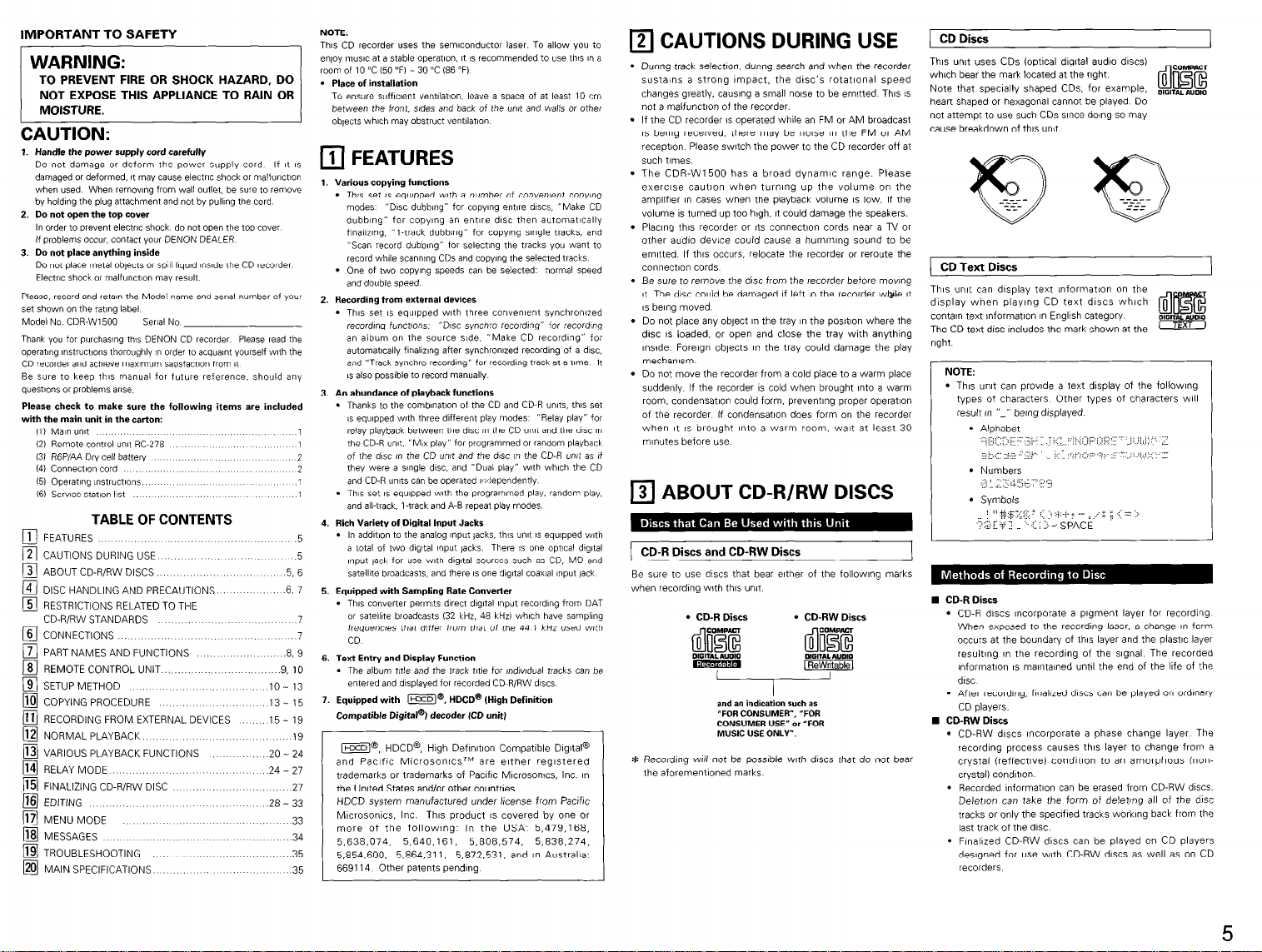
) CD Discs
This un,t uses CDs (optIcal dIgItal aud!o discs)
which bear the mark located at the right.
Note that specially shaped CDs, for example,
heart shaped or hexagonal cannot be played. Do
not attempt to use such CDs since dang so may
cause breakdown of this unit
mxrALA”DIO
CD Text Discs
The unit can display text informatIon on the
display when playing CD text discs which
contan text nformatlon I” English category
The CD text disc includes the mark shown at the In
right.
l
Th,s un,t can prowde a text display ot the followlng
types of characters Other types of characters WIII
l
Numbers
I
I
_/.. i: :3
l
Symbols
l
CD-R discs wxorporate a pigment layer for recording
When exposed to the recording laser. a change I” form
OCCURS at the boundary of this layer and the plastic layer
resulting I” the recording of the sIgnal. The recorded
information IS maIntained unt!l the end of the life of the
disc
. After recording, finalized discs can be played on ordinary
CD players
n CD-RW Discs
l
CD-RW discs mcorpoiate a phase change layer. The
recordmg process causes this layer to change from a
crystal (reflectlvel condrtmn to an amorphous (noncrystal) condltlon
l
Recorded lnformatlon can be erased from CD-RW discs.
D&t/on can take the form of deleting all of the disc
tracks or only the specifed tracks working back from the
last track of the disc.
l
Flnallzed CD-RW discs can be played on CD players
deslgned for “se with CD-RW discs as well as on CD
recorders
DIGRF~~
5
Page 6
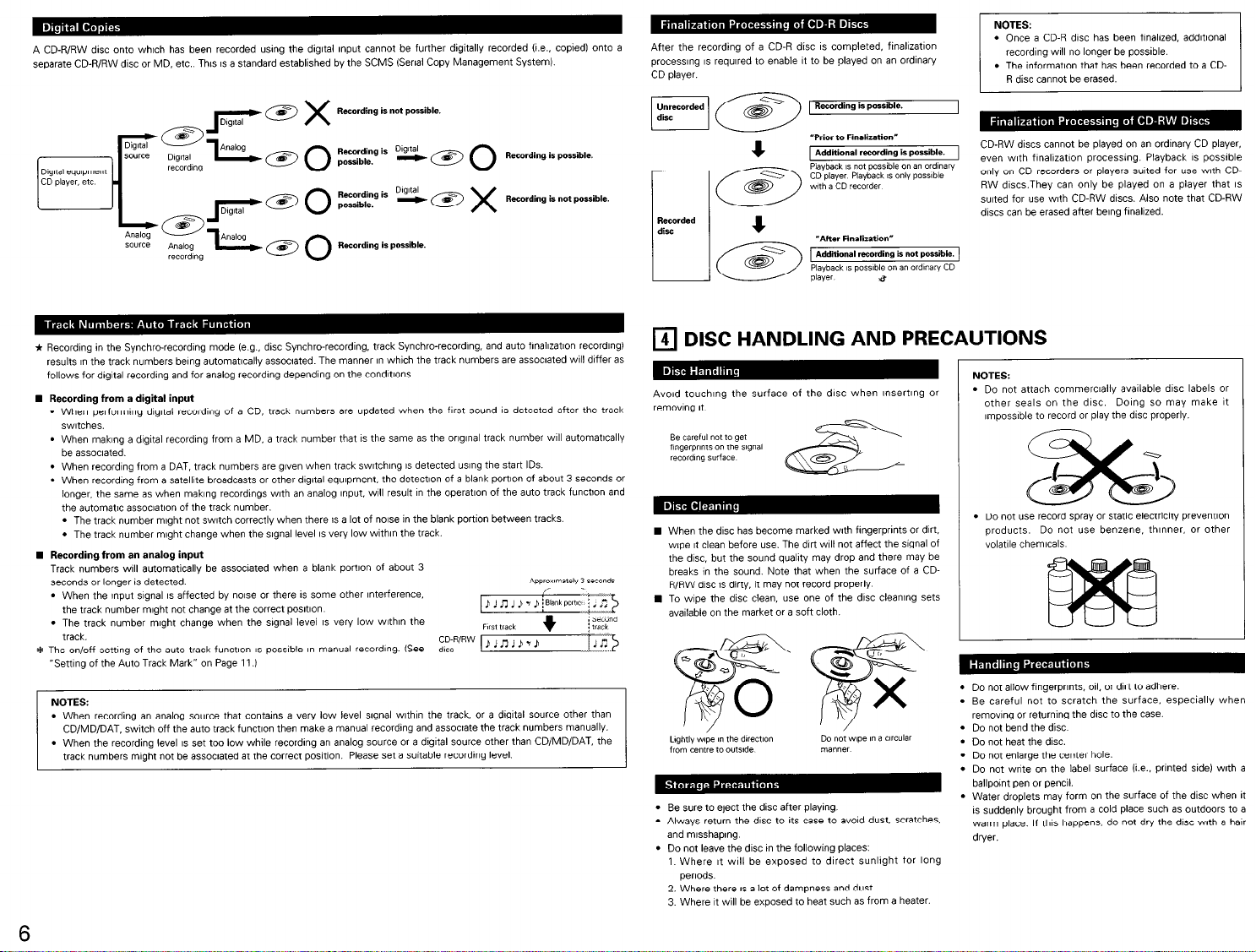
A CD-RIRW disc onto whtch has been recorded using the digltal Input cannot be further digitally recorded (I.% coped1 onto a
separate CD-R/RW disc or MD, etc.. This IS a standard establlshed by the SCMS (Serial Copy Management System).
* Fiecordlng in the Synchro-recording mode (e.g.. disc Synchro-recording. track Synchro-recording. and auto finallzatlon recording)
results in the track numbers being automatIcally assoc!ated. The manner in which the track numbers are assoaated will differ as
follows for digital recording and for analog recording depending on the condltlons
n Recording from a digital input
l
When performIng dIgItal recording of a CD, track numbers are updated when the first sound IS detected after the track
switches.
l
When maklng a digital recording from a MD, a track number that IS the same as the orIgInal track number WIII automatically
be associated.
l
When recording from a DAT. track numbers are glen when track swltchlng IS detected using the start IDS.
l
When recording from a satellite broadcasts or other dlgltal equipment. the detectlon of a blank port1011 of about 3 seconds or
longer. the same as when maklng recordtngs with an analog Input. WIII result I” the operation of the auto track function and
the automatic assoclatlon of the track number.
l
The track number might not switch correctly when there IS a lot of Norse in the blank portion between tracks.
l
The track number might change when the slgnal level IS very low withln the track.
n Recording from an analog input
Track numbers will automatically be assoctated when a blank portion of about 3
seconds or longer is detected.
l
When the Input sIgnal IS affected by nase or there is some other Interference.
the track number might not change at the correct posltlon
l
The track number might change when the slgnal level IS very low within the
track.
* The on/off setting of the wto track function IS possible I” manual recording. (See
“Setting of the Auto Track Mark” on Page 11 .I
NOTES:
l
When recording an analog source that contains a very low level slgnal wIthIn the track, or a dIgItal source other than
CD/MD/DAT, switch off the auto track function then make a manual recording and asswate the track numbers manually.
l
When the recording level IS set too low while recording an analog source or a digltal source other than CD/MD/DAT. the
track numbers might not be associated at the correct posftlon. Please set a suitable recording level.
;,;;R’RW P J
.
n 1 Ji 7 P -1,s:
After the recording of a CD-R disc IS completed, finallzatlon
processing IS required to enable It to be played on an ordinary
CD player.
Recorded
disc
“After Finalization”
Additional recording is not porrible.
IS possible on an ardmaw
q
DISC HANDLING AND PRECAUTIONS
CD
AvoId touching the surface of the disc when lnsertlng or
remo”l”g It
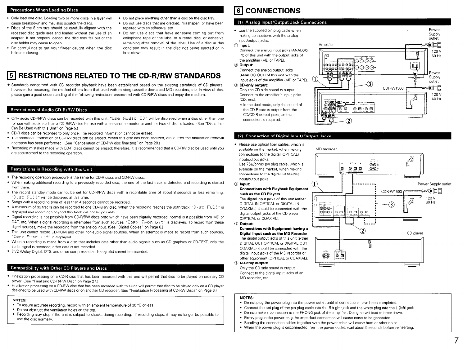
n When the disc has become marked with fingerprints or dirt.
woe It clean before use. The drrt WIII not affect the signal of
the disc. but the sound quality may drop and there may be
breaks in the sound. Note that when the surface of a CDR/RW disc IS dirty. ,t may not record properly
. To wipe the disc clean, use one of the disc cleaning sets
-
a&able on the market or a soft cloth.
I
l
. Be careful not to scratch the surface, especially when
l
l
l
l
l
Be sure to eject the disc after playing.
l
Always return the disc to its case to avold dust, scratches,
and mlsshaplng
l
Do not leave the disc in the following places:
1. Where It will be exposed to direct sunlight for long
periods.
2. Where there IS a lot of dampness and dust.
3. Where It will be exposed to heat such as from a heater.
l
. Once a CD-R disc has been finalized, addItIonal
recording WIII no longer be possible.
l
The information that has been recorded to a CD-
Lot be erased.
CD-RW discs cannot be played on an ordinary CD player,
even with flnalizatnn processing. Playback IS possible
only on CD recorders or players swted for use with CDRW dwzs.They can only be played on a player that IS
sulted for use with CD-RW dws. Also note that CD-RW
discs can be erased after being flnallzed
. Do not attach commercially available disc labels or
other seals on the disc. Doing so may make It
. Do not use record spray or static electricity prevention
products. Do not “se benzene. thinner, or other
volatile chemicals
uuu
Do not allow fIngerprInts, oil, or dirt to adhere.
removing or returning the dasc to the case.
Do not bend the disc
Do not heat the disc.
Do not enlarge the center hole.
Do not wrote on the label surface (~.e.. prlnted side) wth a
ballpoint pen or pencil.
Water droplets may form on the surface of the disc when it
IS suddenly brought from a cold place such as outdoors to a
warm place. If this happens, do not dry the disc wth a bar
dryer.
6
Page 7
l
Only load one disc. Loading two or more discs I” a layer WIII
cause breakdown and may also scratch the discs.
l
DISCS of the 8 cm sze should be carefully allgned wth the
recessed disc guide area and loaded wthout the “se of an
adapter. If not properly loaded, the disc may fall o”t or the
disc holder may cease to open.
l
Be careful not to get your finger caught when the disc
holder IS clang
q
RESTRICTIONS RELATED TO THE CD-R/RW STANDARDS
* Standards concerned wth CD recorder playback have been established based on the ex,stl”g standards of CD players,
however. for recording, the method differs from that used with ewtfng cassette decks and MD recorders, etc. In view of this.
please gain a good understandlng of the followng restrfctaons associated wth CD-R/RW dascs and enjoy the medium.
l
Only audn CD-RIRW discs can be recorded with this urxt “IL&E:
for use with audto such as a CD-RIRW disc for use wth a personal computer or another type of disc !s loaded (See “DISCS that
Can Be Used with this Unit” on Page 5 )
l
CD-R discs can be recorded to only once The recorded InformatIon cannot be erased.
l
The recorded lnformatlon of CD-RW discs can be erased. When this disc has been flnallzed, erase after the flnallzatlon removal
operation has been performed (See “Cancellation of CD-RW disc flnallzlng” on Page 28 1
l
Recording mistakes made wth CD-R discs cannot be erased: therefore, It IS recommended that a CD-RW disc be used until you
are accustomed to the recording operat,on.
l
The recording operation procedure IS the same for CD-R discs and CD-RW discs
l
When maklng addlt!onal recording to a previously recorded disc, the end of the last track IS detected and recording IS started
from there
l
The record standby mode cannot be set for CD-RIRW discs with a recordable time of about 8 seconds or less remanlng.
l
l
l
l
l
l
l
l
c ” WIII be dIsplayed at this tune.
Songs with a recording time of less than 4 seconds cannot be recorded
A maxmum of 99 tracks can be recorded to one CD-RIRW disc When the recording reaches the 99th track, “Q 8 5.
displayed and recordings beyond this track WIII not be possible.
DIgItal recording IS not possible from CD-R/RW discs onto which have been dlgltally recorded, normal 1s !t possible from MD or
DAT. etc When a dlgltal recording IS attempted from such sources. “iaw ?ror-i 8 h / -i” IS displayed. To record from these
dIgItal sources, make the recording from the analog Input. ISee “DIgital Copses” on Page 6.1
This unit cannot record CD-ROM and other non-audio signal sources. When an attempt IS made to record from such sources.
S( I.1 > ‘,..
--‘/. ,../I.- t t ” ,s dlsplaved
When a recording IS made from a disc that Includes data other than audio signals such as CD graphics or CD-TEXT, only the
audio slgnal 1s recorded; other data IS not recorded
DVD (Dolby DIgItal, DTS, and other compressed audio signals) cannot be recorded.
Finalization processing on a CD-R disc that has been recorded with this unit will permit that disc to be played on ordinary CD
Player (See “Flnallzlng CD-R/RW DISC” on Page 27.)
Flnallzatlon processng on a CD-RW disc that has been recorded with this wxt will permit that disc to be played only on a CD player
designed to be used vwth CD-RW discs or on another CD recorder (See “Flnallzatlon Processing of CD-RW DISCS” on Page 6.1
NOTES:
’ TO assure accurate recording. record with an ambent temperature of 30 “C or less.
l
DO not obstruct the ventilation holes on the top.
l
Recording may stop if the unit IS subject to shocks during recording. If recording stops, It may no longer be possible to
“se the dasc normally.
l
Do not place anything other than a disc on the disc tray.
l
Do not use discs that are cracked, misshapen. or have been
repared wth an adhewe, etc.
l
Do not use discs that have adhewe coming out from
cellophane tape or the label of a rental disc, or adheswe
remanng after removal of the label. Use of a disc in this
condltlon may result I” the disc not bang ejected or I”
breakdown.
iiiiri i L ‘?: ” WIII be displayed when a disc other than one
Fcil ” IS
q
CONNECTIONS
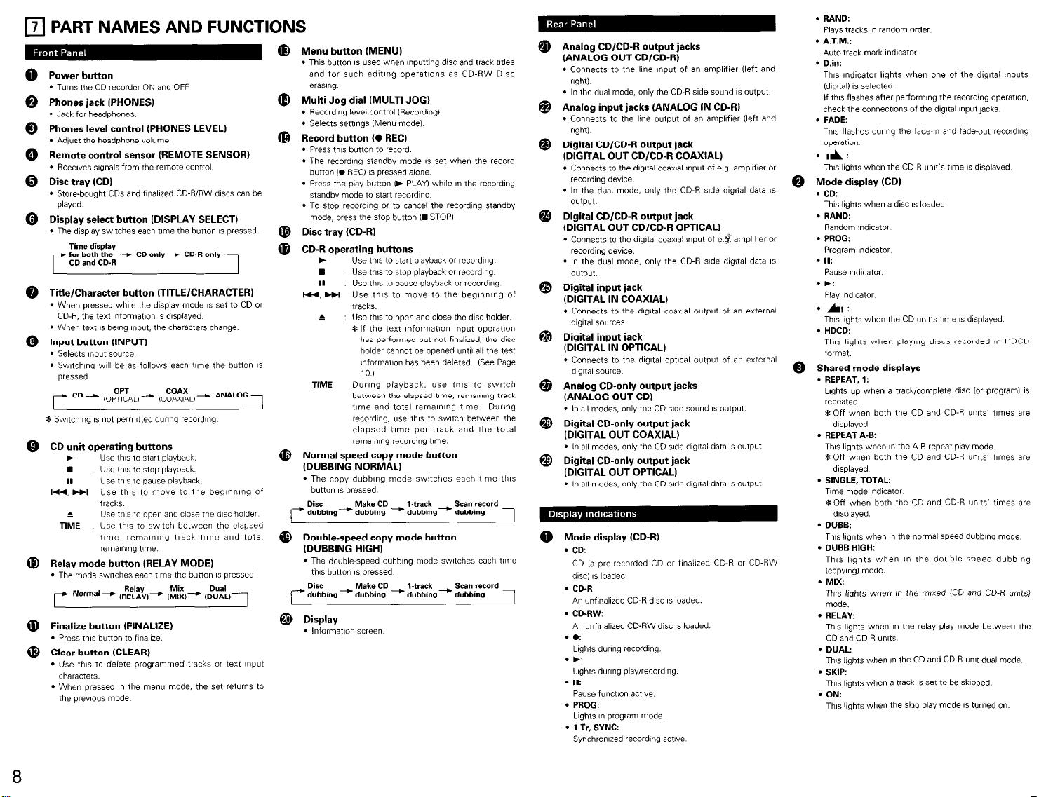
l
Use the supplied pin plug cable when
maklng connectlow with the analog
Input/output jacks.
a Input:
Connect the analog input jacks [ANALOG
IN) of this unit with the output jacks of
the ampllfler (MD or TAPE).
0 Output:
Connect the analog output jacks
(ANALOG OUTI of thfs unit with the
Input jacks of the amplIfter (MD or TAPEI.
@ CD-only output:
Only the CD side sound IS output.
Connect to the ampllfw’s input lacks
(CD, etc )
* In the dual mode, only the sound of
the CD-R side IS output from the
CD/CD-R output jacks. so th!s
connectnn IS requwed.
. Please use optlcal fiber cables, which IS
wallable on the market, when maklng
connectnns to the dytal (OPTICAL)
Input/output jacks
Use 75Qlohms pin plug cable, which IS
awlable on the market, when maklng
connect,ons to the dIgItal (COAXIAL)
Input/output jacks.
0 hmut: Power SUDDIV outlet
Connections with Playback Equipment
such as the CD Players
The dIgItal Input jacks of this ““It (ather
DIGITAL IN OPTICAL or DIGITAL IN
COAXIAL) should be connected with the
dIgital output lacks of the CD player
(OPTICAL or COAXIALI.
0 Output:
Connections with Equipment having a
Digital Input such as the MD Recorder
The dIgItal output jacks of this u”,t (either
DIGITAL OUT OPTICAL or DIGITAL OUT
COAXIAL) should be connected wth the
dIgItal input jacks of the MD recorder or
other equipment (OPTICAL or COAXIAL)
@ CD-only output:
Only the CD side sound IS output.
Connect to the dIgItal Input jacks of an
MD recorder, etc
Ampllfler
MD recorder
en
Power
SUPPlY
outlet
12ov
60 Hz
Power
SUPPlY
outlet
-
120v
60 Hz
NOTES:
l
Do not plug the power plug Into the power outlet until all connectlow have been completed.
l
Connect the red plug of the p,n plug cable !“to the R (right) jack and the whtte plug Into the L (left) jack.
l
Do not make a connection to the PHONO jack of the amplrfler Doing so WIII lead to breakdown
l
Firmly plug I” the power plug. An Imperfect connection WIII cause Norse to be generated
l
Bundltng the connectlo” cables together with the power cable WIII cause hum or other no,se.
l
When the power plug IS disconnected from the power outlet. Walt about 5 seconds before relnsenlng.
7
Page 8
7
PART NAMES AND FUNCTIONS
III
Power button
l
Turns the CD recorder ON and OFF
Phones jack IPHONES)
l
Jack for headphones.
Phones level control (PHONES LEVEL)
l
Adjust the headphone volume.
Remote control sensor (REMOTE SENSOR)
l
Recewes signals from the remote control
Disc tray (CD)
l
Store-bought CDs and flnallzed CD-R/RW discs can be
played
Display select button (DISPLAY SELECT)
l
The display switches each time the button IS pressed.
Time display
for both the --. CD only+ CD-R only
CD and CD-R
r
Title/Character button (TITLE/CHARACTER)
l
When pressed wh+z the display mode IS set to CD or
CD-R, the text information 1s displayed.
1
. When text IS bang Input. the characters change.
Input button (INPUT)
l
Selects input Scl”nx
l
Swtchlng WIII be as follows each time the button IS
pressed
r
&$&. ANALOG
* Swtchlng IS not permitted during recording
CD unit operating buttons
.
Use this to start playback
n Use this to stop playback
Use this to pause playback
II
I.., HI Use this to move to the begInnIng of
tracks
Use this to open and close the disc holder
t
Use this to switch between the elapsed
TIME
t,me, rema,n,ng track t,me and total
remanng t,me
Relay mode button (RELAY MODE)
l
The mode switches each time the button IS pressed
Normal- ,~f~y,+
r
Finalize button (FINALIZE)
l
Press this button to fInalwe.
Clear button (CLEAR)
l
Use this to delete programmed tracks 01 text ~np”t
characters
l
When pressed I” the menu mode, the set returns to
the ~rwous mode
Mix DWil
IMIXI- (DUALI)
Menu button (MENU)
l
This button IS used when ,nputt,“g disc and track titles
and for such edmng operations as CD-RW DISC
ermng.
Multi Jog dial (MULTI JOG)
l
Recording level control (Recording).
l
Selects settings IMenu mode)
Record button (0 REC)
l
Press this button to record
l
The recording standby mode bs set when the record
button (0 REC) 1s pressed alone
l
Press the play button (, PLAY) while in the recording
standby mode to start recording
l
To Stop recording or to cancel the recording standby
mode, press the stop button (m STOP)
Disc tray (CD-R)
CD-R operating buttons
.
Use this to start playback or recording.
n
Use this to stop playback o‘ recording
II Use this to pause playback or recording
l44, HI Use this to move to the beglnmng of
1
tracks.
& : Use this to open and close the disc holder.
*If the text Information mput operation
has performed but not flnallzed. the disc
holder cannot be opened until all the test
lnformatlon has been deleted (See Page
TIME Durrng playback, “se thrs to svwtch
10.1
between the elapsed tne, rema”,ng track
t,me and total remalnlng t,me. During
recording. use this to watch between the
elapsed time per track and the total
remalnlng recording time.
Normal speed copy mode button
(DUBBING NORMAL)
l
The copy dubbing mode swatches each time this
button IS pressed
Disc Make CD l-track Scan record
dubbing-) dubbing --c dubbing- dubbing
@ Double-speed copy mode button
(DUBBING HIGH)
l
The double-speed dubbing mode watches each time
this button IS pressed
Disc
7 dubbing --) dubbing --c dubbing- dubbing
$ Display
l
lnformatlon screen
Make CD l-track
Scan record
Analog CD/CD-R output jacks
[ANALOG OUT CD/CD-R)
l
Connects to the lme Input of an ampllfler (left and
right).
l
In the dual mode, only the CD-R side sound IS output.
Analog input jacks (ANALOG IN CD-RI
l
Connects to the line output of an amplifier (left and
rlght)
Digital CD/CD-R output jack
(DIGITAL OUT CD/CD-R COAXIAL)
l
Connects to the dIgItal coawl Input of e.g. ampllfler or
recording device.
l
In the dual mode. only the CD-R side dIgItal data IS
output.
Digital CD/CD-R output jack
(DIGITAL OUT CD/CD-R OPTICAL)
l
Connects to the dIgItal coaxial !nput of e.# ampllfler or
recording device.
l
In the dual mode, only the CD-R side dIgItal data IS
output.
Digital input jack
(DIGITAL IN COAXIAL)
l
Connects to the dIgItal coaxial output of an external
dIgItal soun?s
Digital input jack
(DIGITAL IN OPTICAL)
l
Connects to the dqtal optlcal output of an external
dqtal source
Analog CD-only output jacks
(ANALOG OUT CD)
l
In all modes, only the CD side sound IS outp”t
Digital CD-only output jack
(DIGITAL OUT COAXIAL)
l
In all modes, only the CD side dIgItal data IS output
Digital CD-only output jack
(DIGITAL OUT OPTICAL)
l
In all modes, only the CD side dIgItal data IS output
0 Mode display (CD-R)
l
CD.
CD ,a pre-recorded CD or finalized CD-R or CD-RW
dlsci IS loaded
l
1
CD-R
An unfinallzed CD-R disc IS loaded.
l
CD-RW:
An unflnallzed CD-RW disc IS loaded.
l ez
Lights during recording.
l ,:
Lights during playlrecordlng.
l
II:
pause function active.
l
PROG:
Lights I” program mode
l
1 Tr, SYNC:
Synchronized recording actwe
l
RAND:
Plays tracks I” random order.
l
A.T.M.:
Auto track mark Indicator
l
D.in:
This lndlcator lights when one of the digltal Inputs
(dlgltal) IS selected
If this flashes after performIng the recordng operation,
check the connections of the dIgItal Input jacks
l
FADE:
This flashes during the fade-In and fade-out recording
operation.
*A:
This lights when the CD-R unit’s time IS displayed
Mode display (CD)
0
l CD:
This lights when a disc IS loaded.
l
RAND:
Random indicator
l
PROG:
Program indicator.
l
II:
Pause indicator.
l .:
Play lndlcator
l A:
This lights when the CD unit’s t,me IS dlsplayed.
l
HDCD:
This lights when playing discs recorded in HDCD
format
Shared mode displays
0
l
REPEAT, 1:
Lights up when a track/complete disc (or program1 IS
repeated
*Off when both the CD and CD-R units’ times are
dlsplayed.
. REPEAT A-B:
This lights when ,n the A-B repeat play mode
*Off when both the CD and CD-R units’ t,mes are
displayed.
l
SINGLE, TOTAL:
Time mode lndlcator
*Off when both the CD and CD-R units’ times are
dIsplayed
l
DUBB:
This lights when in the normal speed dubbing mode
l
DUBB HIGH:
This lights when I” the double-speed dubbing
(copyIngI mode.
l
MIX:
Th6 lights when in the mtxed (CD and CD-R unes)
mode.
l
RELAY:
This lights when I” the relay play mode between the
CD and CD-R units
l
DUAL:
This lights when in the CD and CD-R unit dual mode
l
SKIP:
This lights when a track IS set to be skipped
l ON:
Th,s l,ghts when the skip play mode IS turned on
8
Page 9
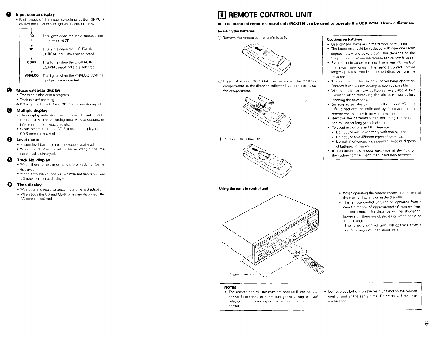
@ Input source display
l
Each press of the mput switching button (INPUT)
causesthe lndlcators to ltght as described below.
CD
This lights when the Input so”lce 1s set
to the nternal CD.
1
OPT
Th,s lights when the DIGITAL IN
OPTICAL ,nput jacks are selected
1
COAX This lights when the DIGITAL IN
COAXIAL Input jacks are selected
1
ANALOG Th,s lights when the ANALOG CD-R IN
I
0 Music calendar display
l
Tracks on a disc or I” a program
l
Track I” playlrecordlng.
*Off when both the CD and CD-R tomes are displayed.
@ Multiple display
l
This display lndlcates the number of tracks, track
number, play tnvz, recording tome, VBIIOUS operatlonal
Information. text messages, etc
l
When both the CD and CD-R times aie dlsplayed. the
CD-R time IS displayed
Q Level meter
l
Record level bar. lndlcates the audio signal level
l
When the CD-R unit IS set to the recording mode, the
,np”t jacks are selected
Input level IS dIsplayed
@ Track No. display
l
When there IS text information, the track number IS
dlsplayed.
l
When both the CD and CD-R times are displayed. the
CD track number 1s displayed.
0 Time display
l
When there IS text Informatvan, the tme IS displayed
l
When both the CD and CD-R t!mes are displayed, the
CD time IS dIsplayed
8 REMOTE CONTROL UNIT
cl
n The included remote control unit (IX-278) can be used to operate the CDR-WI500 from a distance.
Inserting
the batteries
0 Remove the remote control unit’s back Ild
0 Insert the two R6P (AA) batteries I” the battery
compartment, I” the dIrectjon lndlcated by the marks InsIde
the compartment.
0 Put the back Ild back on
Using the remote control unit
Cautions on batteries
l
Use R6P (AA) batteries I” the remote contlol unit
l
The batteries should be replaced with new ones after
approximately one year, though this depends on the
frequency wth which the remote control un!t is used.
l
Even If the battews are less than a year old, replace
them with new ones If the remote control unit no
longer operates even from a short distance from the
main untt
l
The Included battery IS only for verlfylng operation
Replace It with a new batten/ as soon as possible.
l
When ,nsert,ng new batteries, wa!t about two
m,n”tes after removing the old batteries before
,nserting the new ones.
l
Be sure to set the batteries I” the proper “0” and
“0” directlons. as lndlcated by the marks in the
remote control unit’s battery compartment.
l
Remove the battera when not using the remote
control un,t for long perlods of t,me.
l
To avad explosions and fluId leakage:
l
Do not use one new battery with one old one.
. Do not “se two different types of battera
. Do not short-clrcut, disassemble, heat or dispose
of batteries I” flames.
l
If the battery fluld should leak, w~oe all the flud off
the battery compartment, then insert new batteries
l
When operating the remote control ““It. point It at
the man unit es shown I” the diagram.
l
The remote control unit can be operated from a
dnect dMance of approxnately 8 meters from
the ma,” “nit. This distance WIII be shortened.
however, if there are obstacles or when operated
from an angle.
(The remote control un,t WIII operate from a
horlrontal angle of up to about 30”.1
NOTES:
l
The remote control ““It may not operate If the remote l Do not press buttons on the ma,” ““It and on the remote
sensor is exposed to direct sunlight or strong artiflctal
light, or If there IS an obstacle between It and the remote malfunction.
control “n,t at the same time. Doing so WIII result I”
sense
9
Page 10
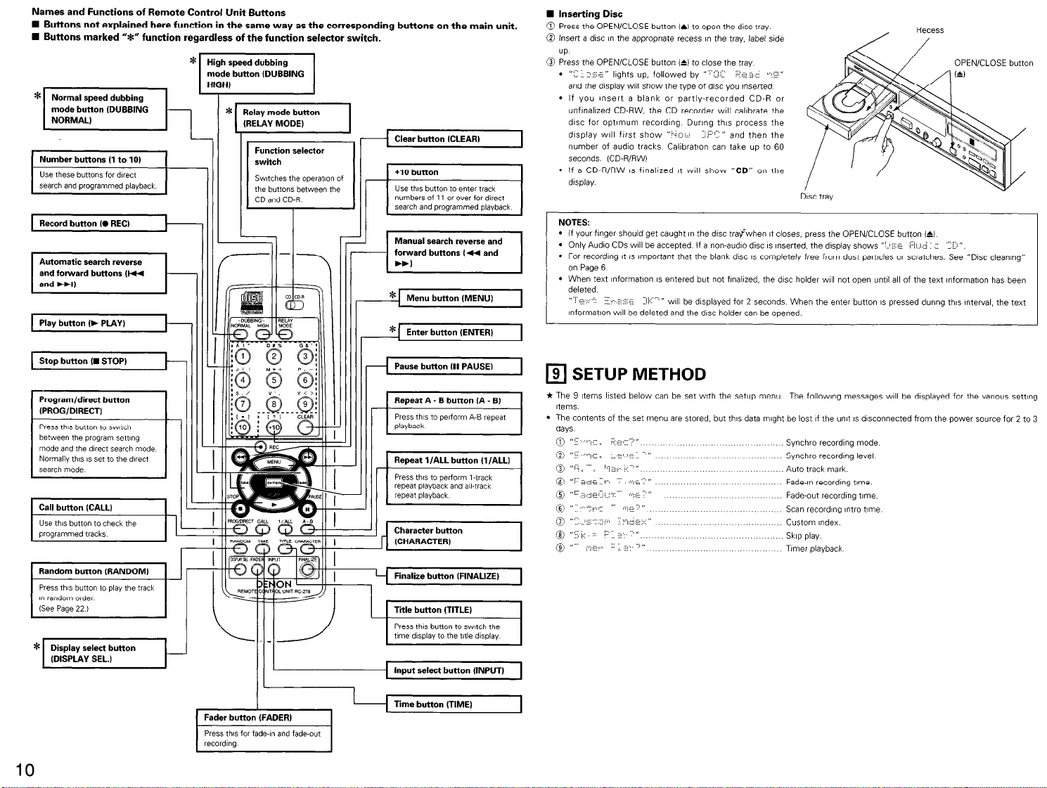
Names and Functions of Remote Control Unit Buttons
n Buttons not explained here function in the same way as the corresponding buttons on the main unit.
W Buttons marked 3” function regardless of the function selector switch.
*
Normal speed
1 ;II (DUBBING Q-
-w
search and programmed playback.
Record button (0 REC)
Stop button (m STOP)-- ( 1 1
Program/direct button
(PROG/DIRECT)
Press this button to switch
between the program semng
mode and the dtrect search mode
Normally this IS set to the direct
search made
dubbing
Function selector
switch
Switches the operation of
the buttons between the
CD and CD-R
I
L
Clear button (CLEAR)
numbers of 11 or ova for direct
search and programmed playback
Manual search reverse and
forward buttons (44 and
* Menu button (MENU)
* Enter button (ENTER)
Pause button (II PAUSE)
Press this to perform A-B repeat
71
repeat playback and all-track
repeai playDacK
n Inserting Disc
0 Press the OPEN/CLOSE button (5) to open the disc tray.
@ Insert a dw in the appropriate recess ,n the tray, label side
UP.
@ Press the OPEN/CLOSE button (&) 10 close the tray
. “” T:,E”
and the display WII show the type of drsc you tnserted
l
If you !“sert a blank 01 partly-recorded CD-R or
unflnallzed CD-RW, the CD recorder WIII calibrate the
disc for opt!m”m recording During this process the
drsplay ‘&III first show ““1. .I=“-“’ and then the
number of audio tracks Calibratton can take up to 60
seconds (CD-R/RW)
l
If a CD-RIRW IS flnaiized ,t WIII show “CD” on the
display.
NOTES:
. if your finger should get caught I” the drsc tray%vhen It closes, press the OPEN/CLOSE button (6)
l
Only Audio CDs WIII be accepted If a non-audio disc IS Inserted. the display shows ”
l
For recording it IS important that the blank disc IS completely free from dust particles or scratches. See “DISC cleaning”
on Page 6
l
When text lnformatlon IS entered but not flnailzed, the disc holder WIII not open until all of the text mformatw has been
deleted
,I ” -: .,,z -- 3k,” ,I
lnformatlon WIII be deleted and the disc holder can be opened.
I
1
q
* The 9 Items listed below can be set with the setup menu
1 ; IreA-Bb”ttc.nIA-BI
Items.
l
The contents of the set menu are stored, but this data might be lost If the umt IS disconnected from the power source for 2 to 3
days
0 I> .; ,_
0 ”
@ ,-i-,, - / - ,I
@ “’ &de:’
@ ,.c; .@-, . . . . _- il
I
@I ”
0” _-x
lights up, followed by “-3.:: 2 :
_. _
WIII be displayed for 2 seconds When the enter button IS pressed during this tnterval. the text
SETUP METHOD
-. II
:I
“‘7:: ., Synchro recordmg level.
-i-..: -- // ”
3: z. ”
6”
DISC tray
: i, i:i : 7 ‘1 “.
The following messages WIII be dlsplayed for the various setting
Synchro recording mode.
Auto track mark.
Fade-in recordmg tome.
Fade-out recording r,me.
Scan recording ,ntro t,me
Custom Index.
Skip play.
Tamer playback
OPEN/CLOSE button
1 Random button (RANDOM)
Press this button to play the track
I” random order
(See Page 22.)
I
10
Fader button (FADER)
Press thts for fade-In and fade-out
171
Press this button To switch the
tme d,splay to the Me display
Input select
Time button (TIME)
button
(INPUT)
I
Page 11

11) Setup Method
11
(Man unttl
(Remote control unit)
I31 Setting the Synchro Recording Level
l
This sets the synchro record!ng start level when synchro recording IS used.
(See Page 18.1
* When usfng synchro recording, recording WIII start when the level of the Input slgnal exceeds a set value Recording V/III stop
when the signal cont,n”es to be at level that IS lower than the set value for 10 seconds 01 longer
(Man unit)
(Remote control un~r)
1 2,3 2
1 Swtch on the power.
Press the menu button and turn the ,og dial on the main un,t 01 use the automaw search buttons on the remote control
2
unit to dtsplay “: : :i..,t= $e!-ii : ”
3
Press the enter button and enter the setup mode
(2) Setting the Synchro Recording Mode
* Perform the synchro recording mode settings. (See Page 18.1
(Man unit)
I
I
I
t
12,W
-
Set the unit to the setup mode, then turn the jog dial of the man unit 01 press the automatic search button of the
1
remote control to display ”
Press the enter button and set the synchro recording selecton mode
2
-
Turn the ,og dial of the ma,” unit 01 press the a”tomat,c search button of the remote control. then select the synchro
recording mode.
“3 :<‘y,,z ”
3
‘.p:;,::,. II
-.... .=
z,/“i,;. I ,I, )“”
; ii”‘: -”
-
Press the enter button and set the synchro recording mode
I.-
4
WTnote control mt1
I
2
Z4
lr3
t 4
I
I I
1,2;3,4
Set the unit to the setup mode, then turn the jog dial of the man unit or press the automatic search button of the
1
remote control to display “: 1;
2 Press the enter button and set the synchro recording selection mode.
I !
Turn the ,og dial of the ma” unit or press the automat,c search button of the remote control, then set the synchro
recording level.
3
l
The setup value IS dlsplayed in the multlple display area. “2~ - .: ”
* The Setting range IS from -54 dB to -30 d6. variable I” 6 dB steps
Press the enter button and set the synchro recording level
4
. ” 1 .J L
I I
(4) Setting of the Auto Track Mark (ATM)
(Main unit)
” wll be &splayed
-$.,‘Ey ”
IRemote control unit)
1,2;3,4
Set the unit to the setup mode, then turn the log dial of the Mann unit or press the automaw search button of the
1
remote control to display ‘lr- ~~‘; “la .?”
Press the enter button and set the auto track mark seiectlon mode
21
Turn the jog dial of the man unit or press the automatic search button of the remote control to select auto track mark
on or off
3
l
The selected mode lndicatlon WIII flash. ‘“i;i-~.XG C”
U
1,3
-2,4
-I,3
Press the enter button and set the auto track mark on or off.
4
. (,i:
= Ts pi.:
.I.*-. ,) or ‘,L ; “” ; r,,,iai.
; i’.’ ” will be dlsplayed
Page 12
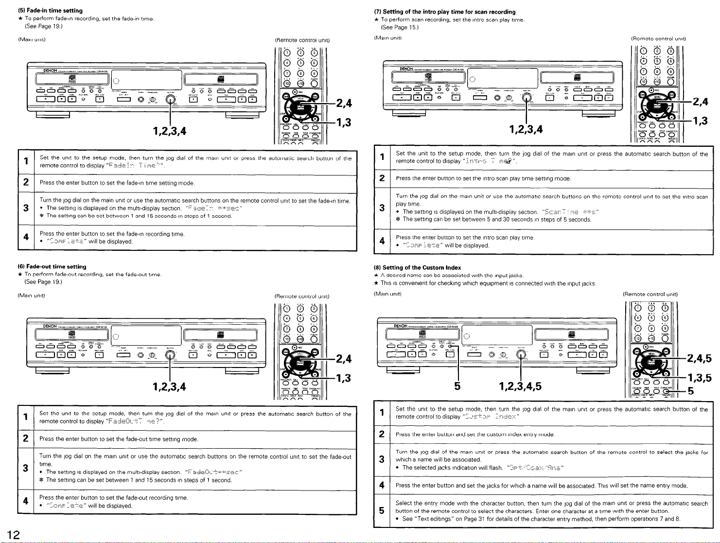
(51 Fade-in time setting
* To perform fade-In recording. set the fade-In time
6ee Page 19 )
(Main unit)
(Remote control unit)
(7) Setting of the intro play time for scan recording
* To perform scan recording. set the r~tro scan play tome
6ee Page 15 )
(MN- unit)
(Remote control unit)
I
I
I
I I
1 ,ZW
Set the “n,t to the setup mode, then turn the ,og dial of the ma,” unit or press the a”tomatlc search button of the
1
remote control to d,splay “F 2.~4 i -- mr ”
Press the enter button to set the fade-In t,me setting mode
2
Turn the jog dial on the Mann unit or use the automatrc search buttons on the remote control unit to set the fade-In time.
l
The sett,n<r is dIsplayed on the multwdlsplay sectlo” ” . ..%. = ‘-‘+~%ji”
3
8 The sett,ng can be set between 1 and 15 seconds I” steps of 1 second.
Press the enter button to set the fade-In recording t,me.
4
. “‘Y. )jQjz >:
(61 Fade-out time setting
* To perform fade-out recording. set the fade-out t,me
6ee Page 19.1
(Man unit)
I
” WIII be dlsplayed
I
memote control unltl
I
I
I
1.2,3,4
Set the unit to the setup mode, then turn the log dnl of the man unit or press the automat!c search button of the
1
remote control to display “F .i zleCIi?- -. 7”
Press the enter button to set the fade-out tvne setting mode.
21
Turn the jog dial on the man unit or use the automatic search buttons on the remote control unit to set the fade-out
time.
3
’ The setting IS dIsplayed on the multi-display sectlo”
8 The setting can be set between 1 and 15 seconds I” steps of 1 second.
Press the enter button to set the fade-out recording t,me.
4
. ” ;I-.? Le.‘,: 2” w,ll be d,sp,,gyc+,.
” s.~,,:,. +.i... ?,: ”
.2,4
.I,3
,2,4
,I,3
I
I
I
I
I
12,W
I
Set the unit to the setup mode, then turn the jog dial of the Mann unit or press the automatic search button of the
1
remote control to display ” -‘:i’ :.
Press the enter button to set the Intro scan play time setting mode
2
Turn the log dial on the main unit or use the automatic search buttons on the remote control unit to set the !ntro scan
play t,me
3
l
The sen~ng IS dIsplayed on the multwdlspiay sect~o”. ‘2. =--
* The setting can be set between 5 and 30 seconds I” steps of 5 seconds
Press the enter button to set the Intro scan play time
4
. ”
:iF 3:6” WIII be d,splayed
(81 Setting of the Custom Index
* A dewed name can be associated with the Input lacks.
* This IS convenent for checking which equnpment IS connected wth the Input jacks
(Mar unItI
I I
I
5
Set the unit to the setup mode, then turn the jog dial of the Mann unit or press the automatlc search button of the
1
remote control to display “lip -? -j- z : ”
2 Press the enter button and set the custom Index entry mode
Turn the log dial of the ma,” unit or press the automaW search button of the remote control to select the jacks for
which a name will be associated
3
l
The selected jacks lndvzatlon vail flash. “.:?-:. -.;.a~.? -..;”
4 Press the enter button and set the jacks for which a name WIII be assoclated This wll set the name entry mode.
Select the entry mode with the character button, then turn the ,og dial of the ma” “nit or press the automaW search
button of the remote control to select the characters Enter one character at a t,me with the enter button.
5
l
See “Text edltlngs” on Page 31 for details of the character entry method, then perform operations 7 and 8
<. z& “,
I
l,Z3,4,5
: ”
(Remote control wxt)
I
I
,2,4
,I,3
2,4,5
1,3,5
5
12
Page 13

ISI Setting the Skip Play Mode
* This allows playback that skips over tracks to which you do not want to hsten.
(See ‘“Reglstration of the tracks to which you do not wsh to listen” on Page 29 for information on the setting of such tracks I
(Main unit)
(Remote control unlt)
1 ,ZW
Z4
I,3
q
COPYING PROCEDURE
About copying
* Copying can be performed easily from the set’s CD unit onto the CD-R unit
* There are two copying speeds (normal and hIghI and four copying modes.
l
The mode switches as described below each time the normal speed copying button (NORMAL) or the high speed copying
button (HIGH) IS pressed.
Disc dubbing: In this mode, entire CDs can be copied onto CD-R/RW
(” --: 1 - I” IS dlsplayed 1
1 1
Make CD: In this mode, entIre CDs can be copled onto CD-R/RW then finalized automatically
(“,‘k,}!:, ‘:[.I Cw>c ” IS d,sp,ayed.)
Set the unit to the setup mode, then turn the jog dtal of the man unit or press the automatic search button of the
1
remote control to display “‘- = : ” ”
Press the enter button and set the skip play selectlot- mode
2
Turn the ,og dial of the ma,” un,t 01 press the automat,c search button of the remote control to select skip play on or off
3
l
The selected mode Indication will flash. “-
Press the enter button and set the skip play to on or off.
4
. “E;F[I I
NOTES:
l
Flnaltrlng the disc when tracks to which you do not want to lIsten have been reglstered, results in the skip play mode
automatlcally being swltched on
l
Skip play IS not possible on CD players that lack a skip play function
l
Program play and random play are not possible when there has been ieglstration of tracks to which you do not want to
listen
(101 Timer play mode setting
* Timer playback IS possible. (See Page 24 )
(Main unit)
I
Set the wt to the setup mode, then turn the jog dial of the man unit or press the automatic search button of the
1
remote control to display ” “.a: .-
1
,I or,’ -x _
” WIII be d&splayed.
1
,ZW
”
.”
(Remote control unlt)
I
I
I
Z4
I,3
I 1
1TR dubbing: In this mode, single tracks on CDs can be copled
I”: .- Y I --.1” is displayed I
Scan REC dubbing: In this mode, the dewed tracks can be selected from CDs and copied
,-s; .i,z ,,
l
The recording level IS automatically set to the default value (0 0 dB)
l
The repeat and random play modes are canceled when the copy mode IS set.
l
Dung normal speed copying you can llsten to the sound as you copy
l
Dung high speed copying no sound IS produced
l
No signals are output from the dqtal outputs during high speed copywg.
. During copying, buttons other than the CD or CD-R stop buttons do not functlon
l
When CD TEXT compat<ble CDs are copied, the disc names and track names are also copled
NOTES:
l
Copying 1s normally performed with dIgItal signals, but If dtgltal copying is not possible due to SCMS restnctlons. copying
IS performed with analog signals In addltlon. copying IS always performed at normal speed (See Page 6.1
l
Analog slgnal copying IS always performed in the normal speed mode.
l
If when the copying mode IS set the recordable tfme on the CD-FIRW is shorter than the time of the CD source you are
trying to copy, ”
check the disc’s recordable time
. If the disc name has already been Input on the disc on which you are recording. only the track names are copled
l
For some CDs, the text cannot be copled because of copyright protect,on
dlsplayed.
l
Do not turn off the power or unplug the power cord whtle ”
Dang so may render the disc unusable
.; Isi,-
” IS displayed )
” IS displayed and both the CD and CD-R urxts are set to the stop mode
In this case ” pi.:.::: =-i i 1 ” is
-?- : .” IS dlsplayed after recording IS completed
If this happens,
Press the enter button and set the timer play selection mode
2
Turn the jog dial on the Mann unit or use the automaw search buttons on the remote control un11 to turn the tfmer play
mode on or off
3
l
The selected mode lndicatlon wll flash. “‘I,? .“‘.’ ” ”
Press the enter button to set the timer play mode on 01 off
4
. “- / “-L; :. .. -ii-, ” 0‘ ” .:,.y.; : .:
” WIII be displayed
13
Page 14

(11 Copying entire discs
(Man unItI
k----l
I I
5
Load the CD you want to copy Into the CD unit
1
Load the CD-RIRW onto whtch you want to record Into the CD-R unrt
2
Press the normal 01 high speed copyng button (NORMAL or HIGH) to display “!all
3 BiJl&“.
-
Press the enter button to set the copying mode.
4
l
The CD unit IS set to the pause mode, the CD-R unit to the recording standby mode
-
Press the CD or CD-R unit’s play button
l Copymg starts
l
If the “t4lai-e :E” mode has been selected, flnailzatlon starts automatically after copying IS completed (See Page
27.) Once flnalwatlon IS completed the stop mode IS set automatlcally
l
To stop I” the mlddle of copying. press the stop button on the CD or CD-R unit.
l
If the program modes are set for the CD unit beforehand. copyng IS performed accordingly.
1
I I I-
42 5 5-
(Remote control unttl
/ \
-4
T-- _‘i.i!x ” or “‘46’; = T
(2) Copying one track at a time
(Man unlt)
6 1 .4 2 6
Load the CD you want to copy ,nto the CD unit
’ I
Load the CD-R/RW onto which you want to record [“to the CD-R ““It.
2
Press the normal or high speed copyng button (NORMAL or HIGH) to display “Z-k- 1 ~:!x. ‘?P”
3
Press the enter button to set the copying mode.
4
. The CD unit IS set to the pause mode. the CD-R unit to the recording standby mode
Use the CD unit’s automat,c search buttons to select the track you want to record
51-
Press the CD or CD-R “nit’s play button.
l
Copying Salts.
6
l
When copying IS completed, the CD-R unit IS stopped
l
To stop I” the mlddle of copytng. press the stop button on the CD or CD-R “nit
(Remote control unit)
3-
5-
6-
NOTE:
l
If you wtsh to (“put text data, select the “?
disc has been flnallzed
14
I.&r ” mode With CD-R discs, text data cannot be Input after the
--.-
Page 15

(3) Selecting tracks to be copied while scanning CDs and copying the selected tracks
q
* The intro scan playing t&me can be set at the setup men” (Page 12)
(Mann unIti
i
Load the CD you want to copy Into the CD unit.
i
Load the CD-R/RW onto which you want to record Into the CD-R unit.
2
Press the normal or high speed copying button (NORMAL or HIGH) to display “5X:-*
3
Press the enter button to set the copying mode
4
l
The CD-R unit 1s set to the recording standby mode, and intro scan playback starts on the CD unit
Set the tracks you want to record.
l
For tracks you want to record, press the enter button
l
For tracks you do no want to record, press the autcxnat~c search forward button.
* Once all the tracks have been scanned, the CD unft IS set to the pause mode, “‘*’
5
the “PROG” lndlcator lights
l
Check the settings on the mus,c calendar, and if they are OK press the enter button
l
If the sett,ngs are wrong, press the stop button then repeat steps 1 to 5
Press the CD or CD-R unit’s play button
l
Copying starts
6
l
When copyng IS completed, the CD-R unit is stopped
l
To stop ,n the middle of copying. press the stop button on the CD or CD-R unit
-
4;5 2
(Remote control unit)
/
6-
: : %!I ”
I:?.‘“” IS d!splayed. and
:::
-4,5
RECORDING FROM EXTERNAL DEVICES
l
When recording on an already recorded disc, recording automatIcally starts from the end of the secton last recorded. When
doing so, pay attentn” to the rema,n,ng ttme.
l
To clear the ent,re content of the d!sc and record from the begInnIng, first e‘ase the entn? disc. “(2) Erasing the tracks” Page
28.
l
To aswre accurate recording, record wth an amblent temperature of 30 “C or less.
l
Recording may stop If the ““It IS sublect to shocks dung recording If recording stops, It may no longer be possible to “se the
disc normally. (“c. zc F;_,-- :w “I
l
Switch to the normal or dual mode when recording Operation IS not possible in the relay or mix mode
* Your recorder offers several recording modes.
* Setting is possible usfng the method of “Setup Method” on Page 11
recording of the complete disc 01 a program simply by
l
In this mode, flnallzatlon IS performed automatlcaily after synchronlred recording
of all the tracks
l
To manually start a recording wnply by piewng the REC button
:--. “..j ..,,,, ,_._
,::; y: gz,,_: j/_ .:_j
Some remarks on recording:
l
When Auto track IS ON (default setting). track numbers WIII automatically be vweased during recording
l
By programnxng the source first, a comptlatlon can be recorded.
.-: :‘. i’.
i,..l ‘i’ ‘i
l
To make a synchronized recording of a single track simply by starting the source.
NOTES:
l
Analog recording IS not possible I” the Make CD mode
l
Use the copy mode to record HDCDs. Such discs may not be recorded
properly when recording from the exterior.
. Do not turn off the power or unplug the power cord while “h10i..
? i:z” IS dlsplayed after record,ng IS completed. Doing so may render the
disc unusable
?i i
15
Page 16

1. Manual recording
(1) Starting analog recording
(Man unit)
Select the CD-R side. -
42
12) Starting digital recording
l
This set Includes a sampling rate converter.
(Remote control unit)
f
8
When recordtng DATs or satellite broadcasts (32 kHz or 48 kHz) whose dIgItal jnput slgnal sampling frequency IS different from
that of CD (44 1 kHz), the sampling frequency IS automatically converted to 44.1 kHr
(Main unlt)
Select the CD-R side.
(Remote control mt)
42 8
16
8-
Turn on the power
Load the CD-R/RW disc that 1s to be recorded
Perform the operation of “Setup Method 12) Setting the Synchro Recording Mode ” on Page 11 and select the Synchro
off mode
When “s!ng an already recorded DISC, press the TIME button to check the recordable time
l
The time display watches between the total recorded time and the recordable tfme each time the TIME button IS
pressed.
Press the (“put swltchlng button (INPUT) and select the analog source
l
The “ANALOG” display will Ilght.
Perform the operation of “Setup Method” on Page 11 and select on/off of the ATM function.
l
ATM Function on
The “ATM” display WIII light When a blank portlo” lof about 3 seconds 01 longer1 of the recording input s,gnal IS
6
detected, the track number IS automatically associated and recorded
l
ATM Function off
This IS recorded as the folIowIng track
Start playrng the selection you want to record on the CD player, cassette deck, etc.
5
-
Press the record button IO REQ.
8
l
The recording standby mode IS set.
-
Adjust the recording level with the ,og dial and press the enter button
. Adjust the Input level adlustment control (INPUT LEVEL) so that the “OVER” lndlcator does not light even when the
volume IS loudest. After adjusting. set the scwrce to be recorded to the standby mode
* The recording level can be
l
The set recording level WIII be stored I” memory. but thts data might be lost If the un!t is not connected to a power
swrce for 2 to 3 days
-
Press the play button 0 PLAY).
I(
l
Recording starts
Start playng the selection you want to record on the CD player, cassette deck, etc.
n
set
I” advance using the menu mode.
8
Turn on the power
’ I
Load the CD-RIRW disc that is to be recorded
2
Perform the operat!on of “Setup Method 121 Setting the Synchro Recording Mode” on Page 11 and select the Synchro off mode.
3
When us,ng an already recorded DISC. press the TIME button to check the recordable t,me
.
The time d,splay watches between the total recorded tome and the recordable tome each tome the TIME button IS pressed
Press the ,nput sw,tch!ng button (INPUT) and select the dlgltal source (Optical or Coaxiali
5
* The lndlcator for the selected ,nput source (“CD”, “OPT” or “COAX”) lkghts
Perform the operation of “Setup Method” on Page 11 and select on/off of the ATM function
l
ATM Function on
The “ATM” display will light. When a blank portlo” (of about 3 seconds or longer, of the recording ,np”t signal IS detected, the
6
track number IS automatically associated and recorded
. ATM Functaon off
This IS recorded as the followng track
Start playing the selection you want to record on the CD player, MD recorder. etc
71
Press the record button (0 RECI
8
* if the “D in” lndlcator 1s fiashlng. check the connect,ons to the dlgttal lnputjacks
Adjust the recordtng level wth the ,og d,al and press the enter button
* Adjust the input level ad,“stment control (INPUT LEVEL) so that the “OVER” indicator does not lkght eve” when the volume IS
loudest. After adlustlng, set the swrce to be recorded to the standby mode
9
* The recording level can be set I” advance “sing the men” mode.
- The set recording level WIII be stored I” memory. but this data might be lost If the unit IS not connected to a power source for 2
to 3 days
Press the play button 0 PLAY)
IO
l
Recording starts.
Play the selecf~on to be recorded on the CD player, etc
I1
NOTES:
* “CD” can be selected by pressing the Input selector button, but manual recording from the set’s CD unit IS only possible !n the dual
mode. (Refer to “Dual mode” on Page 26. 27).
l
When you do not wish to change the dIgItal recording level, set the ,og d,a, so that “‘1,. 1.5. ’
WIII be made wthout changing the input slgnal level
* The recording level can be adjusted over a range of - - to +I2 dB for analog (“put recording and from -m to 0 dB for dlgltai input
recording Note that the dtsplayed sett\ng values may include a degree of error ,n terms of calculation processing
l
When the record,ng level IS - =e, “:,. -Ui /- -. --SE ”
IS dIsplayed and audio 1s not output.
a ,?-dE” IS dIsplayed The recording
-1
1
I
I
I
Page 17

(3) Stopping recording
(Man unit)
Select the CD-R side. -
(4) Adding track numbers during recording
(Mann unit)
(Remote control unit)
Select the CD-R s,de.
During recording, press the stop button (m STOP)
1
l
The stop mode IS set automatically once the end of the recordable time is reached.
I I
NOTES:
l
When performlng dIgItal recording of CD or MD, the track numbers are recorded automatlcallv ISee Page 6 1
l
When recording digltal sources other than CD or MD, track numbers are automatlcallv added when blank Sections are
detected (See Page 6 )
l
During dIgItal recording from CD or MD, the track number may not change If the same track IS programmed twice In a
row or if the single track repeat mode IS set
l
It IS not possible to make dlg,tal recordings of D,scs which have already been recorded dlgltally The CDR.W1500 includes
a serial copy management system This system llmlts reproduction of dIgItal signals on dIgItal audio devices to “one
generation” Use analog recording to record Discs orlglnally recorded dlgltally
* The CDR.W1500 IS for use I” pwate homes and may not operate properly if used (to record, etc.1 in combination with
professional equipment or other dewes not designed for use I” private homes.
l
To eject the Disc If the “1
the recording pause mode is set. first press the stop button (m STOP), then press the open/close button (*
OPEN/CLOSE) to elect the Disc.
L: _
II or ‘,Z ,,,
: I- ” message IS displayed during dIgItal recording and
* Track numbers can be added during recording regardless of the recording mode.
I
During recording. press the record button (0 RECI
. When the record button (0 RECI IS pressed during recording, a
track number IS added at that pant
1
. A new track number cannot be added for approximately 4
seconds after the last track number
(51 Stopping recording temporarily
l
Record!ng can be stopped temporarily then resumed from the same point
During recording, press the pause button (II PAUSE)
. When the pause button (II PAUSE) IS pressed during
recording, the pause mode IS ser at that point and the track
2
number changes
l
Press the play button 1, PLAY) to resume recording
l
A blank sectlo” of approximately 2 seconds 1s Inserted before recording resumes
Press the record b”m’” i. REC)
+
1s track
1st track
2nd track
2nd wxk
17
Page 18

2. Synchronized recording of the Disc
(DISC SYNCHROI
* This mode IS used when recording all the tracks of the CD or MD on the playback side
(Mar” unit)
3. Synchronized recording of the single track
IlTr SYNCHRO)
* This mode IS used to record only one track
(Man unrt)
(Remote control unit)
Select the CD-R side. -
Perform the operation of “Manual recording” on Page 16. perform the settings of the Input jacks and the recording
1
level, and set the stop mode. mode.
Perform the procedure at “Setup Method (2) Setting the Synchro Recording Mode” on Page 11 and select the disc
synchro mode or the make CD mode.
2
l
The “SYNC” indication will Ilght.
Press the record button (0 REQ.
3
. The recording pause mode IS set and “i! i sip: Z-*-K+ --iz” or “i.tai ~1 ,I I” IS dlsplayed.
Use a CD player, cassette deck or other source to play the tracks that you wish to record.
l
Recording will start automatlcally.
4
l
In the make CD mode, flnalizatlon IS performed automatically after recording stops.
* Please also see “Setup Method (3) Setting the Synchro Recording Level” on Page 11
l
To stop synchro recording, press the stop button.
l
Please also see “Setup Method 13) Setting the Synchro Recording Level” on Page 11.
Select the CD-R side -
Perform the operato” of “Manual recording” on Page 16. set the Input jacks and the recording level. and set the stop
1
Perform the operaton of “Setup Method (2) Setting the Synchro Recording Mode” on Page 11 and select the track
synchro mode.
2
l
The “1Tr SYNC” lndicatro” lights
Press the record button (0 REC)
3
l
Thus sets the record-pause mode and displays “: i _
.:, ,.y,,:/.‘,f.(r”
Use a CD player, cassette deck or other source to play the tracks that you wish to record.
l
Recording will start automatically.
4
* Please also see “Setup Method (3) Sertlng the Synchro Recording Level” on Page 11.
l
To stop synchro recording, press the stop button
l
Please also see “Setup Method (3) Setting the Synchro Recording Level” on Page 11.
NOTE:
l
If you wash to input text data. select the “I! i 5.:
the disc has been finalized.
18
E.:*-or’-.-0” mode
With CD-R discs, text data cannot be Input after
Page 19

4. Fade-in and fade-out recording
* It IS possible to record by gradually nzreaslng the volume (fade-In) or decreasing it (fade-out)
(1) Fade-in recording
Perform the procedure at “Manual recording” step 1 to 8 (Page 16)
1 I
Start playng the selection you want to record on the CD player. cassette deck, etc
21
Press the fader button on the remote control unit.
l
‘% 38 I;?” IS displayed. and “FADE” flashes during the fade I” caper&on
3
l
The recorded sound IS gradually increased from a recording level of-m to the set recording level in the set time.
* Also refer to “Setup Method (5) Fade-In t,me setting” (Page 12).
(21 Fade-ouf recording
During recording. press the fader button on the remote control unit.
l
“Fade l:li~~i” ,s dIsplayed, and “FADE” flashes during the fade out operat,on.
1
l
The recorded sound is gradually decreased from the set recordtng level to a recording level of-w in the set t!me.
* Also refer to ‘“Setup Method 16) Fade-out time setting” (Page 12).
12 NORMAL PLAYBACK
0
1. Starting playback
First try playing the tracks in order.
Load the disc to be played
II I
l
Press the PLAY button 0) to start CD play
l
“)“llghts up and the track number and track time of the track I” play appear on the display.
2
l
Press the TIME button once, tw,ce or three t,mes to see:
Remalnlng track time, total remanng time. elapsed track tnx?.
Select the deck to be operated.
(Remote control unit)
NOTE:
l
‘3 ? i! ! i”3” wll be displayed at such tomes as when a disc IS not loaded, the disc cannot be read properly due to
scratches or dvt, or the disc IS loaded upside down
2. Starting playback
Press the stop button (m STOP)
l
Playback stops.
3
l
The stop mode IS set automaticallY once all the tracks on the disc have been played
19
Page 20

13 VARIOUS PLAYBACK FUNCTIONS
0
In addition to normal playback, the CDR-W1500 also offers the playback functions described below.
1. Playing a certain track (remote control unit only)
_.......................................................................... Direct Search
(Remote control unit)
f
- Select the deck to be operated
(2) Searching backward
During playback, press and hold in the manual search reverse
button (+4).
l
Normal playback rewmes from the pant at which the button
IS released.
l
Manual search stops and playback starts If the begInnIng of
the first track on the disc IS reached while pressing the
manual search reverse button (~1.
l
For high-speed backward search wIthout hearing the sound.
press the manual search averse button (U) while I” the
I I
pause mode.
‘::
‘;c’
+,“..*,, ‘..*/ ‘..*,, ‘..&‘..J
SklP SklP
‘j :* ,
‘;c’
SklP Skip SklP
-1
Use the number buttons I1 to IO) and the cl 0 button to Input the number of the dewed track
l
For example:
1
Press button q to listen to the 4th track, buttons m and q to listen to the 12th track, m, m[ and KJ to
listen to the 30th track. Playback beglns from that track.
2. Finding the desired position while listening to the sound
Use this function to skip rapIdly through the disc while llstenlng to the sound.
l
This functton comes I” handy when you want to find a certan sectlo” wIthIn a long track
(Remote control unIti
2-
..__._.__....._.__._........................................... Manual Search
f
- Select tl he
1
deck tc
‘be operated
NOTE:
l
There may be a slight break I” the sound when returning to normal playback from the manual search mode.
3. Finding the beginnings of tracks during playback
(1) Moving ahead to the beginning of the next track
(Main unit)
Press the automatic search forward button (WI
l
During the search operat!o”. press the automatic search
1
forward button (W) aga,” to move further on to the
begInnIng of the following track.
. . . . . . . . . . . . . . . . . . . . . . . . . . . . . . . . . . . . . . . . . . . . . . . . . . . . . . . . . . Automatic Search
a
Select the deck to be operated -
+ ~
2nd track
‘L. . . __ . ..I2
3rd track
4th track
11) Searching forward
During playback, press and hold I” the manual search forward
button (-1
l
Normal playback resumes from the point at which the button
IS released
. Playback stops If the end of the last track on the disc IS
1
reached while pressing the manual search forward button
C-j.
’ For high-speed forward search wlthout hearing the sound,
press the manual search forward button (H) while I” the
pause mode
20
2nd
track
*,,+h+h,?,.J:$
Playback SklP SklP Sktp sap sap
3rd
track track
4th
Page 21

(2) Moving back to the beginning of the current track
(Man unit)
Select the deck to be operated
5. Playing tracks in a certain order . . . . . . . . . . . . . .._.__.................................................................... Programmed Playback
l
Use this function to select certal” tracks from the disc and program them to play I” a certain order.
l
Up to 30 tracks can be programmed.
Select the deck to be operated.
(Remote control ““It)
(Main unit)
/
Press the automatlc search reverse button 044
l
During the search operation. press the a”tomatlc search
1
reverse button (I441 aga,” to move further back to the
begInning of previous track
4. Stopping playback temporarily __.._.._.__.__.__.............................................................................................. (
l
Use this function to stop playback temporarily then resume from the same point
Select the deck to be operated
3rd rrack 4th track 5th track
(Remote control unit)
‘-EI
I
3
In the stop mode, press the PROGlDlFiECT button
1
l
The “PROG” lndlcator lights
Use the number buttons and the +lO button to select the tracks for programmed playback.
2
. For example, to program the 3rd. 12th and 7th tracks, press [PROG/DIRECTI. a. m. q and 0.
Press the play button (W PLAY).
3
l
The tracks are played I” the programmed order
l
To check the contents of the program, press the CALL button The programmed tracks appear in the programmed order
on the display each time the CALL button IS pressed.
l
To change the program. press the CLEAR button while I” the stop mode, then program the dewed track. The last
programmed track IS replaced with the newly Input track.
l
To clear the entire program. press the PROGlDlRECT or open/close (t OPEN/CLOSE) button while I” the stop mode.
NOTES:
l
The single track repeat mode and A-E repeat mode cannot be set during programmed playback
l
Programs wth total playing t,mes of over 99 nxnute.3 can be set, but the t,me WIII not be dlsplayed properly.
l
Programmed playback IS not possible with non-finalized discs
I’
3
I’
l-
Dwng playback, press the pause button ill PAUSE).
l
The pause mode IS set.
1
l
Press the play button 0 PLAY) to resume playback from the
point at which the pause mode was set.
4th track
-;e
0 Press the piay buttc’n i. PLAY,
5th track
6th tlack
21
Page 22

6. Playing in random order
l
Use this function to play all the tracks on the dec once in random order.
. . . . . . . . . . . . . . . . . . . . . . . . . . . . . . . . . . . . . . . . . . . . . . . . . . . . . . . . . . . . . . . . . . . . . . . . . . . . . . . . . . . . . . . . . . . . . . . . . . . . . . Random Playback
7. Playing repeatedly
(1) Playing a single track repeatedly ISingle Track Repeat1
.___._........,..,...............,......................,....,................................................... j Repeat Playback 1
(Remote control unItI
(Man unit)
2
In the stop mode, press the RANDOM button.
1
l
The “RAND” lndlcator lights.
Press the play button 0 PLAY).
l
During normal playback.
Tracks are automatically played I” random order
2
l
Dwng the all-track repeat mode.
All tracks are played once I” random order. then repeated I” another random order.
l
To cancel the random play mode, either set the stop mode or press the RANDOM button again
NOTES:
l
The single track repeat mode and A-B repeat mode cannot be set dwng random playback
l
Random playback IS not possible with “on-flnallzed discs.
2
Select the deck to be operated
l-
(Remote control unlt)
(Man unit)
2
x
Press the repeat l/ALL button once
1
l
The “REPEAT 1” Indicators light on the display and the s@? track repeat mode IS set
Use the automat,c search buttons ( I44 and FW ) to select the track to be played repeatedly
2
Press the play button (F PLAY).
l
Playback starts
l
Once the selected track ends. It IS played again from the
beginning.
l
The single track repeat mode can also be set by presstng the
repeat l/ALL button dung playback The current track IS
played repeatedly.
. To cancel the single track repeat mode. press the repeat
l/ALL button repeatedly until the “REPEAT” lndlcator turns
Select the deck to be operated.
22
Page 23

(2) Playing all tracks repeatedly [All Track Repeat]
Select the
deck to be operated.
(Remote control unit)
Press the repeat l/ALL button twice.
1
l
The “REPEAT” lndlcators light on the display and the all track repeat mode IS set.
Press the play button 0 PLAYI.
l
The disc IS played repeatedly
l
The all track repeat mode can also be sat by pressing the repeat l/ALL button twice during playback
2
l
If the repeat l/ALL button IS pressed during programmed playback, the tracks are played repeatedly I” the
programmed order.
l
To cancel the all track repeat mode, press the repeat l/ALL button repeatedly until the “REPEAT” lndlcator turns off.
NOTES:
l
The single track repeat mode cannot be sat during programmed playback or random playback
l
Repeat playback IS not possible with non-flnallzed discs.
13) Playing a section between any two points repeatedly IA-B Repeat1
* This function allows you to play a certa,” sectn” wthln a track repeatedly
(Remote control “IIt)
-
During playback, press the repeat A-B button at the posltion at which you want to start repeatIng (point A)
1
l
The “REPEAT A-” lndlcator lights
Press the repeat A-B button agal” at the pos,t,on at which you want to stop repeating IpoInt B).
l
The “REPEAT A-B” lndlcator Ilghts. the plckup returns to po,nt A, and the sectlo” IS played repeatedly
.
(1, Press the repeat A--B button 12, PlfE the repeat A-B button
dlm”‘J playback %W”
iPOInt A, mm w
2
I
2”dtrack / 3rd track ! 4th track
Select the deck to be operated.
i
-
l
To stop A-B repeat playback. press the repeat A-B button on the remote control unit until the “REPEAT” lndlcator turns off
The A-B repeat mode IS canceled and normal playback starts from the beglnnlng of the current track
l
If the stop button (e STOP) IS pressed, the A-B repeat mode IS canceled and the stop mode IS sat.
NOTES:
l
A-B repeat playback IS not possible during programmed playback or random playback.
l
The automatic and manual search functions cannot be used during A-B repeat playback or when setting point B
l
When A-B repeat playback IS canceled when point B IS set on a different track from point A, playback resumes from the
begInning of the track that IS playing when the A-B repeat mode IS canceled.
l
A-B repeat playback is not possible with non-finalized discs.
23
Page 24

8. Timer playback
l
A separately sold audio trier can be used to start playback or recording at a specific time
l
Also refer to the operat,ng ,nstruct,ons for the audio t,mer and ampllfler.
l
The program and relay modes can also be used
(I) Connections
I21 Timer playback
iMan unit)
CDR-Wt500 ,ThlS set,
(Remote control unltl
q
RELAY MODE
* Various types of playback and recordlng can be performed through relay operation between the set’s CD and CD-R ““1%
* There are three relay modes.
* The set mode IS stored I” the memory, but the data may be cleared If the power IS not turned on for 2 or 3 days
l
The mode swtches as shown below each time the RELAY MODE button IS pressed
l
The disc I” the CD ““At and the one I” the CD-R
untt are played one after the other.
l
+
MIX mode.
1
Dual mode:
i
Normal mode: l Either the CD or the CD-R unrt can be operated.
Programmed play and random play of the disc in
the CD unit and the one I” the CD-R ““It can be
performed as If the two discs were a single disc.
l
The CD and CD-R units can be operated
independently
s
II..
,.,-.
,, --
r- 3 ”
L
* Recording, flnallzlng and edltlng are not possible I” the relay or Max mode
Turn on the power of the CDR-W1500 and the connected components.
1
Perform the procedure at “Setup Method 1101 Tamer play mode setting” (Page 131 and make the twner playback on
2
semng.
I I
3 Load the Disc for timer playback 1x0 the CDR.WI500
I I
e ampllfler’s Input selector to “CD”
Press the play button (, PLAY)
5
l
Play the disc to check the volume
I I
Set the audio timer for the dewed time.
l
The power of the components connected to the audio tvner turns off.
6
l
When the set tome IS reached, the power of the various components turns on automatically and playback beglns from
I I
track one.
24
Page 25

1. Relay play
* With the relay play mode it IS possible to play the disc in the CD side and the one I” the CD-R side. relaying between them.
* The programmed play and random play modes can be preset for the discs in the CD and CD-R units.
Select the CD side
2. Mix mode
* In the Max mode. programmed play and random play of the d!sc in the CD unit and the one IV the CD-R unit can be performed as
if the two discs were a single disc
(1) Mix programmed playback
(Remote control unit)
1
IMan unit)
I
7- I I I -
4 2 1 1
Load the discs you want to play in the CD and CD-R “nits
1
Press the RELAY MODE button and select “r 31; 3 : P:“’
2
l
The “RELAY” indicator Itghts
Use the CD or CD-R section repeat l/ALL button on the remote control “n,t to turn the repeat mode on or off
l
The l-track repeat mode cannot be set I” the relay mode.
l
The relay opeiat~on IS performed as shown below according to the comblnatlon of the relay and repeat modes
3
Relay play starts when the CD unit’s play button IS pressed.
. The sound IS output from the CD/CD-R output jacks
4
. To qwf the relay mode, press the relay mode button and select ” I.
l
The disc I” the side that IS not operat,ng can be replaced during relay playback
NOTE:
l
When relaying between a CD and CD-R. the dtgltal data from the CD/CD-R dtgltal output terminal IS interrupted
momentarily The dIgItal input of the connected external device IS temporarily unlocked at this time
Repeat mode
Repeat on “REPEAT”
Repeat off CD side playback + CD-R side playback + Stop
Indicator Ilt
CD side playback + CD-R side playback
Relay operalo”
3
$ ”
1
(Man unit)
Load the discs you want to play I” the CD and CD-R ““1%.
1
Press the RELAY MODE button and select ”
2
l
The “MIX” indicator Ilghts.
Press the CD or CD-R une’s PROG/DIRECT button on the remote control unit to set the program mode.
3
l
The “PROG” indicator Ilghts.
Follow the procedure at “Programmed playback” on Page 21 to program the tracks I” the order I” which you want to
play them
l
You can program tracks for both the CD and CD-R units by uswg the CD/CD-R selector switch on the remote control
4
u”,t to switch between them
l
Up to 30 tracks can be programmed
MIX programmed playback starts when the CD or CD-R unit’s play button IS pressed.
l
The sound 1s output from the CD/CD-R output jacks
5
l
To quit the mix mode, press the relay mode button and select “!
NOTE:
l
When relaying between a CD and CD-R. the dIgItal data from the CD/CD-R dIgItal o”tp”t terminal IS interrupted
momentarily. The digltal Input of the connected external dewce IS temporarily unlocked at this tome.
= La ”
e 7 L = ”
25
Page 26

(2) Mix random playback
(Remote control unit)
(Man unit)
Load the discs you want to play I” the CD and CD-R units
’ I
Press the RELAY MODE button and select “-+
2
l
The “MIX” lndlcator lights
Press the CD or CD-R unit’s RANDOM button on the remote control unit to set the random mode
3
l
The “RAND” lndlcator Ilghts.
MIX random playback starts when the CD a CD-R unit’s play button IS pressed.
l
The sound 1s output from the CD/CD-R output jacks
4
l
To qwt the nxx mode, press the relay mode button and select ‘5 isle F : : ”
NOTES:
l
If the program and random mode IS not set in the nxx mode, the operation IS the same as I” the relay mode IwIth the
repeat mode off).
l
When relaying between a CD and CD-R, the dIgItal data from the CD/CD-R digital output termtnal IS interrupted
momentarily. The digltal (“put of the connected external dewce IS temporarily unlocked at thus tune.
52 i ,s ,: ., *’
3. Dual mode
* In the dual mode, the CD ““It and CD-R ““It can be operated independently
* Manual recording from the man unit’s CD sexton can be performed.
(1) Dual playback
Select the deck to be operated. -
Load the dws you want to play I” the CD and CD-R “nits
1
Press the RELAY MODE button and select “. .z :. = ; :- ”
2
l
The “DUAL” lndlcatar Ilghts.
Dual playback starts when the CD or CD-R unit’s play button IS pressed.
l
The sound of the CD IS o”tp”t from the CD-only wtp”t jacks and the sound of the CD-R IS output from the CD/CD-R
output jacks
l
Only the sound of the CD-R IS output from the headphones jack.
3
l
The display can be swltched wth the DISPLAY SELECT button so that you can check the time !nformatlon. etc.. for
the CD and CD-R.
l
To quit the dual mode, press the relay mode button and select “- t%!c ” 2 ”
(Remote control unit)
26
Page 27

(2) Recording from the CD section
--
I I I I
31
Load the CD you want to copy [“to the CD un,t
1 I
Load the CD-R/RW onto which you want to record ~“to the CD-R ““lt.
2
Press the RELAY MODE button and select “41;~ = 15:’ ”
3
l
The “DUAL” lndlcator Ilghts.
Press the (“put selector button and set “CD”
4
Follow the procedure at “Recording From External Devwes” on Page 15 -19 to record.
l
The display can be swtched with the DISPLAY SELECT button so that you can check the time InformatIon, etc., for
5
the CD and CD-R
l
To quit the dual mode. press the relay mode button and select “1 1 .t Es. + ”
-I
24
(Remote control unit)
q
FINALIZING CD-R/RW DISC
* Finallzlng IS a simple procedure, necessary to’
l
Be able to play recordings on a CD player,
l
Awd further unwanted recordings on a disc.
l
AvoId erasure of tracks on a CD-RW
* This operation IS not possible I” the relay or Max mode
(1) Auto finalizing
Auto flnallzlng IS possible when usv?g the Make CD recording function. See “Copying Procedure” and “Synchronized recording
of the DISC” on Page 13, 18
(2) Manual finalizing
I
Load the CD-R/RW disc that IS to be flnallzed
1
With the recorder stopped press the FINALIZE button.
. I.:
2
i,;;, :
I’ii”” IS dlsplayed.
Switch to the normal or dual mode to perform this operation.
(Remote control unItI
ry
1
I \
Press the ENTER button
l
The display co”“% down through the flnallzatlon.
3
l
On completion, the total number of tracks and the total t!me recorded appears on the display.
l
The disc lnd!cation of the display WIII become “CD”.
NOTES:
l
Make sure the disc IS absolutely free of scratches and dust particles.
l
Finalizung will take at least 2 4 mwtes.
l
During finallzatton. the CD recorder accepts no operating commands.
l
Text data is written to the disc when the disc is finalized. If you want to enter text. this must be done prior to flnallzing.
l
For lnformatlon about cancelllng CD-RW flnallzlng, see “Cancellat!on of CD-RW DISC Flnalizlng (I.%, Unfinalmngl” on Page
28.
l
Never turn off the power or unplug the power cord during flnalvzatlon. Dang so may render the disc unusable.
27
Page 28

16 EDITING
q
* This operation IS not possible I” the relay or nxx mode Switch tc~ the normal or dual mode to perform this operaton
1. CD-RIRW editing
(11 Cancellation of CD-RW disc finalizing (i.e., Unfinalizing)
* This operaton IS valid only for CD-RW dwzs. Flnallzlng cannot be cancelled from CD-R discs
* Use this operation to cancel flnalizlng when addlng further recording to a flnallzed CD-RW disc
* Erasing IS completed in several mnutes.
iRemote Control unit)
f
(2) Erasing the tracks
* This operawan IS v&d only for CD-RW discs.
* Use th,s operatvx to cancel flnallzlng when addlng further recording to a flnalaed CD-RW d!sc and when erasing recorded
tracks.
* ErasIng 1s completed I” several minutes.
(Remote control unItI
f
(Man unit)
7
1 Switch on the power.
Load the CD-RW &SC for which flnal!zlng 1s to be cancelled
2
Press the MENU button, turn the ,og dial of the ma,” ““It or press the a”tomat,c search button of the remote control,
and select the CD-R/RW edn mode
3
. “.I 9;;. ,: // E.2
Press the enter button, turn the ,og d,al of the ma,” u”,t or press the automat,c search button of the remote control, and
select the unfwalue mode
4
. ”
-= ;> =.. a.<~- ” IS d,splayed.
Now, press the enter button, turn the jog dial of the mar- unit or press the automatic search button of the remote
control, and select the unfinallze mode
5
. “-ii” i: -2. . . ” ,s&tp,q,ed.
Press the enter button.
6
. “‘::.p-. a .:: ,::
-..
Press the enter button agal”.
7
l
When unflnalmng 1s completed, the disc type display wll be “CD-RW”.
” IS displayed
--
” IS de&y&
I I
I
I II-
I 3,4,5,6,7 2 3
1 Switch on the power
Load the CD-RW disc that IS to be erased
2
Press the MENU button, turn the jog dial of the man unit or press the automat!c search button of the remote Control,
and select the CD-RIRW edlt mode
3
. “‘* :1;.-et...
Press the enter button, turn the jog dial of the Mann unat or press the automaw search button of the remote control. and
select the all tracks erase mode
4
. ” I. E -+::.e-“’ ,s&p,ay&,
Now, press the enter button, turn the jog dial of the main ww or press the automatic search button of the remote
control, and select the all tracks erase mode.
5
. .17ii __
Press the enter button
6
. “. ZE”
Press the enter button aga”
. ,,.,
7
_. :.- : ” display IS flashing
l
When erasIng IS completed, the time display will be “f ..! iiir ‘: : ”
- ” 1s dlsplayed.
: ” IS dlsplayed.
:3.“’ IS displayed
28
Page 29

(3) Erasing one or more tracks away from the last track
* When erasing a flnallzed CD-RW disc, first unflnallze the disc.
(4) Registration of the tracks to which you do not wish to listen
* Tracks to which you do not wish to Ilsten, such as those conta,n,ng recording eriors. can be set so that they will be skipped
over durtng play.
(Remote control unit)
Swtch on the power
’ I
Load the CD-RW disc that IS to be erased
2
Press the MENU button, turn the ,og dial of the ma,” U”I~ or press the automatic search button of the remote control,
and select the CD-R/RW edit mode.
3
. .I-
Press the enter button. turn the,og dial of the ma,” ““,I or press the automat,c search button of the remote control, and
select the one-track erase mode.
4
5
6
: :I/ =~-.a :i’ ” ,s d,&,yed
. ”
Now. press the enter button. turn the jog dial of the man knot or press the automatic search button of the remote
control. and select the one-track erase mode
. II --
Press the enter button
. ”
Turn the jog dial of the ma!n unit counterclockwise or press the a~romat~c search REV button of the remote control. and
select the number of tracks you want to erase
l
The mwc calendar display of the selected track number WIII flash
Press the enter button agal”
. ,,-
l
When erasing IS completed, the number of tracks that rema,” followng the erasure are dIsplayed I” a portIon of the
music calendar.
” IS dIsplayed
- .
” is displayed
: ” 1s dIsplayed
:. ” display IS flashing.
1 Switch on the power
I
2
3
4
5
6
7
8
9
10 .*-
Load the CD-R/RW disc that contains tracks that you would llke to skip in playback
Press the MENU button, turn the ,og dial of the ma,” wxt or press the automaX search button of the remote control.
and select the CD-RIRW edlt mode.
. ,,‘‘7 i
Press the enter button, turn the ,og dial of the ma” ““it or press the automatic search button of the remote Control. and
select the skip track setting mode
. ,‘S!
Now, press the enter button, turn the log dial of the man un!t or press the awrnaw search button of the remote
control. and select the skip track semng mode
. ,I t-
Press the enter button.
. />-
Turn the ,og dial of the ma,” un,t or press the a”tomatlc search button of the remote control. and select the tracks you
want to skip Press the enter button and set
l
The musk calendar dxiplay of the selected track number will flash
Repeat Step 7 to add another track.
Press the enter button dung the “. i
. II :- -
_ ii “1’
Press the enter button.
l
The ~IJSIC calendar display of the selected track number IS swtched off.
” 1s displayed.
-. ” IS dIsplayed
” IS dlsplayed
” IS dlsplayed
” IS dIsplayed
-7” IS displayed and the reglstratlon 1s completed
r
” display
29
Page 30

15) Cancelling the registration of tracks to which you do not wish to listen
1 Switch on the power
Load the CD-RIRW disc for which you want to cancel the settngs of undeswed tracks
2
Press the MENU button, turn the log dial of the man unit 01 press the automaw search button of the remote control.
and select the CD-R/RW edit mode.
3
l “CI?R.43;! Ed i t’-” IS &played.
Press the enter button, turn the jog dial of the Mann unft or press the automatic search button of the w-note control. and
select the skip track setting mode.
4
l “Sic i: T~-..aa::. - ” 1s displayed.
Now. press the enter button, turn the jog dial of the man unit or press the automaw search button of the remote
control. and select the skip track setting cancellation mode.
5
l “51~ zz $z les.-.“” 15 displayed,
Press the enter button
6
Turn the jog dial of the man unit or press the automatfc search button of the remote control, and select the track you
want to cancel. Press the enter button and set.
7
l
The mwc calendar display of the selected track number will flash.
(Remote control unit)
/
2. Text editings
n Up to 23 characters can be (“put for the track and dasc titles
(11 Adding disc titles
1 Switch on the power.
2 Load the CD-R/RW disc to which the disc name WIII be afflxed.
Press the MENU button. turn the Jog dial of the main unit or press the automatic search button of the remote control,
and select the TEXT edlt mode.
3
. ”
Press the enter button, turn the log dial of the man unit or press the automatic search button of the remote control to
4
&play “Tey,~ I?-!‘-“‘.
Now, press the enter button, turn the jog dial of the man unit or press the automatic search button of the remote
5
control to d,sp,ay “3 L:C
Press the ENTER button
6
l
: i?” ,s &play&
-iej<i
; tl a’:‘“.
The cursor flashes, lndicatlng the title Input standby mode
Repeat Step 7 to add another cancellation.
8
Press the enter button during the “:f = Z 1’: +:-.
9
. “Sk / 71: Iearl:l}:::-‘” IS d,.@ayed.
Press the enter button.
10
l
“t+xi BVlFi Rer” is displayed and the regnstratwn IS completed.
NOTES:
l
Fanalmng the disc when tracks to whtch you do not want to llsten have been reglstered, results I” the skip play mode
automatically bang switched on.
l
Skip play 15
l
Tracks to which you do not want to lasten can be reglsteredlcancelled 21 times.
l
Program play and random play are not powble when there has been reglstratlon of tracks to which you do not want to
lIsten.
l
It IS not possible to register or cancel tracks you do not want to hear with store-bought CDs or CD-R/RW dtscs that have
been flnallzed.
not
possible on CD players that lack a skip play function
--?,- ” display.
30
Page 31

Input the title
l
Either turn the jog dial on the rna~n unit or use the automatic search buttons (m and HI) on the rem& ContrOt
unit to select the dewed character.
l
Some characters that can be Input on the CD&W1500 cannot be dIsplayed on other models.
mHmmmpJ[;;;;;i
l
The shape of the cu,so, changes each t,me the CHARACTER button IS pressed
IExplanatlon of cursor:]
rj .Capltal letter/number Input mode
7
8
’
’
t
.
:ett
tnA3 .“““”
lAvalIable characters and numbersl
Capital letter/number Input mode
Small letter/number Input mode:
Special character input mode,
l
When the manual search forward button (,b) or the ENTER button IS pressed, the selected character IS set, and the
unit IS set to the Input standby mode for the next character.
l
The Cursor can be moved back by pressmg the manual search reverse button (u) Use this to correct input
characters.
Press the MENU button to enter the input title.
To erase a character, move the c”,so, to that character then press the CLEAR button.
To correct a character, fwst erase ,t, then ,nput the correct character.
Small letter/number Input mode
ABCDEFGHIJKLMNOPQRSTUWVXYZO123456789
abcdefghi~klmnopqrstuvwxyzO123456789
SPACE _! ~.+$y&” (‘j:++* . ..=j. 9.-:.=:‘.‘:‘:2;;1_“.cI:i.-’
SE:
mm.
:ae - :;i
tint I... Li
-: :
E’-:
:
:
:.,i
:...:
Spew character Input mode
(21 Adding track titles
(Remote control unit)
f
(Mar! unltl
1 Switch on the power
Load the CD-RIRW disc to which the track name vvll be afftxed.
2
Press the MENU button, turn the jog dial of the main unit o, press the automatic search button of the remote control.
and select the TEXT edit mode.
3
l
I 1
I I
I I
I I
I I
I I
” r$? t ?d ! -7 ” Is dlsplayed
Press the enter button, turn the ,og dnl of the ma” ““It or press the a”tomatlc search button of the remote control to
4
display “Te. .t 1 .-,‘-“’
Now. press the enter button, turn the ,og dial of the ma,” unit or press the a”tomatlc search button of the remote
5
control to display “;t..:i.:l.
Press the enter button agal”, turn the ,og dial of the ma,” ““It or press the automaw search button of the remote
control, and select the track t,, which you would llke to affix a track name
6
, .I:/ .:-* -
Press the ENTER button
7
l
The cursor flashes, lnducatlng the title Input standby mode
Input the title.
8
. For !nstr”ct,ons on ,“p”tt,ng titles. see step 7 under “(1) Addlng disc titles” on Page 31
Press the MENU button to enter the Input track title.
9
-- ‘?. ‘,‘. I,
” IS dlsplayed.
f
4,5.6.7,8
NOTES:
l
Text edlung IS not possible wth commercial audio CDs or wth finalized CD-R/RW discs
l
A maximum of 23 characters can be stored per Item.
Approximately 900 characters can be input per disc.
l
Entered text Information IS not wntten to the disc until the disc IS flnallzed.
. Even when the power so”,ce IS disconnected. the text lnformatlon IS stored for 2 to 3 days after bang entered when the
disc has not been flnallzed This text information might be lost If the unit IS disconnected from the power source for a
long time.
31
Page 32

(31 Erasing disc titles
(Remote control unlt)
(4) Erasing track titles
(Remote control unltl
1 Load the CD-R/RW disc from which the disc name will be erased
Press the MENU button, turn the ,og dial of the ma,” ““It or press the automatvz search button of the remote control.
and select the TEXT edit mode.
2
. ““ret Ed T -” IS d,sp,ayed.
Press the enter button. turn the log d1.4 of the main unn or press the automaw search button of the remote control to
3
&p,ay “ye>.<-:,, L>-. 35y- “,
Now. press the enter button, turn the ,og dial of the ma” “n,t 01 press the a”tomatlc search button of the remote
4
control to display “B ; : : -- - ”
Press the enter button to define the etasure of the disc name.
5
. ‘I-- /. y3Tt-:”
is displayed
Load the CD-R/RW disc from which a track name wll be erased.
1
Press the MENU button, turn the log dial of the man unit or press the automatic search button of the remote control.
and select the TEXT edlt mode.
2
. ”
< i? 5. - ” IS dIsplayed
Press the enter button, turn the ,og dial of the ma,” un,t 0‘ press the automatic search button of the remote control to
3
d,sp,ay “‘e;.<+ r. -2.~: ”
Now, press the enter button, turn the log dial of the man unit or press the automatic search button of the remote
4
control to display “- :-:
Press the enter button agal”, turn the ,og dial of the ma,” un,t or press the automatic search button of the
control, and select the track for which the track name WII be erased.
5
. ” :..Ts-. 7: ” ,s d,sp,ay&,
Press the enter button to define the erasure of the disc name
6
. “.:y’.~. / 13~5” IS d,sp,ayed
=ey”
remote
32
Page 33

15) Erasing all the track titles and the disc title
(Remote control unit)
Load the CD-RIRW disc from which all the track names and the disc name WIII be erased
II I
Press the MENU button, turn the ,og dial of the mar ““I, o‘ press the automatic search button of the remote control,
and select the TEXT edlt mode
2
. ” ,:: :‘. :
I I
Press the enter button, turn the jog dial of the main unit or press the automatic search button of the remote control to
3
display ” I .: 2’ ”
I I
Now, press the enter button, turn the ,og dial of the man u”,t or press the automatic search button of the remote
4
control to display ” _ L. : ”
‘:‘-“’ IS dlsplayed
17 MENU MODE
0
When the MENU button bs pressed, the menu mode IS set and the set can be operated as shown on the diagram below.
l
l
“*” lndlcates default values
l
Turn the jog dial clockwse to proceed to the “-1” display lndlcator
indicator
MENU MODE
Press the ENTER button to proceed to the “t” display
Press the enter button
5
, I-z,..:=,-;
Press the enter button to define the one erasure
6
l
” = ” IS dIsplayed
NOTE:
Erasure of text is not possible with commercial audio CDs or with flnalzed CD-R/RW discs
l
” “’ IS displayed
33
Page 34

q
MESSAGES
Messages may appear on the display while using the CDR.W1500. The meanings of these messages are explaIned below
Message Meaning
..~ ,..., . . . . . :..., :
i i,,Ji ,,,, ,. .-i
i.....-.. . .._ . ..j
; C, :z: _:-:i : ,,,: g c i:z:
_..._
;.,.i i:::. $Xj p
i-. ‘i :...: ,::~ :::::
i . . . . 2. . . . . . ..
I ! 7.: :
i.2:: g,.:
: iC...
: :
: : ,.... ,...,
z::i : : . ..i : :.._
:,,,:,:~~.:“”
; l:,,,::,.d j __._ i
!. 1
i..:: ii.!
: i.,,,..,.,. 1 ; 11 ; .i::: ijiif!::::
:-_
: : : ,.... ,....
I”.. i .:::.: ____ i :,“: J. .;,
:“‘.
j ,,,, i__,i y I:.’
:--
i yi,;;;i .j, : -.i. :-_
i__
i::> 7 i
i
j. ,... j .:. 7. . ..j.
i. i :
j .‘j !...! !.:_:
;“‘; /:::: j-.
.__: : : . . . .
:...,
E !:::: :-- c’ .-..
L-_
j _j j .::y :-
. . . . . .._._
_::~ :....
j:::: i_:.i f--
:....
:,,, : : ‘i ‘!
;:::i :,,,, :.__: ; . . . . ; i___ : ..i*
: _,,,. : 1 : j,,,: j i,.
j ,::., :;-:
t :-: :,__, ‘I ,_ ,,
i::
..
. . . . :.:_._:i ! .:. _:
i-i i:::i I-.
.,,_. : : ___.
:....
.-, ,, ,, ,...
/ _,__ r r i,,.: ;
; ,,,, i_ i_ i,,,: j_
:....
i... :-.
: __,, r r :___: r
:
;.... $-.,
: ,,,. i..:
z-..
:.i.: ii ._/_. .,j,.
: :
Reading disc lnformatlon
During tray opening
During tray closing
No disc wxted, disc unreadable or disc inserted upside down.
Inserted disc is no audio CD
Updatlng disc contents
No more recordtng possible
No dIgItal recording can be made of the connected source
See “Dtgltal Copies” on Page 6.
Time countdown when flnallzlng a disc
When trywg to record on a flnallzed CD-R or a prerecorded CD
Dung laser power calibration for unflnalized discs
OPC failure dung OPC procedure
(OPC = Optimum Power Callbratlon)
An error has occurred dung recording
Recording or flnallzatlon IS not possible due to a disc fault
Message Meaning
i.. i
. . . . : : : i..:
I
I
I
I
” lndlcates a letter or character.)
(”
: :..A: i. : i”’ .:. 2.
t:< ,... !
; 1 :zf Z.“, i_ i .:::; L,. :
j:::I ‘i 7 ::::I ;-.. : j :::,
i i .i_ .:. . . . . i.. ! :
:
-. . .... 7.
!” ......
!-: I. g ;-
..:_. : :__
; ::::: . . i -.; j”. :,... :::: .r ::-:: i i j.:
.c . . . : : . . ..i ^... . . . . . : . . :’
I:-:: ;> . . . . . i:::i
j .._ ,,,,i i 1 i,,,: r ii
..:..
j ;~L .___. .+.
..___ : ._ . . .
-:-
1. !
:..:: ::_!
: : .,“. ._.:
ty.
r:’ : : ‘I ‘i
:....
i... : _.._ in. c :,..,
,,,.:
..:..
jg.-. Skip IS set for all tracks.
‘I ;y;; -; :::::
.:. ... . ........
_..._ :
,. ,..
,.... :
. . . . L... . . . . . ..i..
/:::: :___, :..., ..;.. ,..., ,____ _.i..
.,,,i :,.:z:::“” i,.
:
:-. j ,, ,,, __,, i
! . . . . r i k.;.f i ._.. s.
23 text characters have already been Input or a total of 900 characters
have already been input
DISC IS not operat,ng properly.
Mode reception has been completed
If the disc is removed, all the text lnformatlon IS cleared.
5
The recordable time on the disc IS shorter than the t!me of the
recording source you are trying to copy
The text lnformatlon IS copy-protected so the text cannot be copled I”
the copy mode.
The CD side track lnformatlon IS bang checked
:-‘. ‘j . . . . :,.., i ,.
i:::; _i_ .:::j j 1 y.,
i.. i ,...: i.. i
: .: : j .j .::: i ; : j j...:
:-
-: y F i j ,,,, ::
i-.
j j i :y.i
i. . . . . . :: i:i ! .i.
34
rlj j ,..._ ,.._.
. . . .
i i :..., 7 :...; :.“. i ,.
: .:::. :
..i. :
:. .y. :::- y:j
. . . . . . ?..
When attempt,ng to edit text for a disc which has no tracks.
No text stored for disc.
iy.
Setting value of the synchro recordrng stal?l”g level
There IS an ncomplete connection of the dqtal Input lack during
dIgItal Input recording, or the tnput signal IS not being Input properly
due to some other factor.
Page 35

q
TROUBLESHOOTING
n Are all the connections correct ?
n Are you following the instructions in the manual 7
n Are the amplifier and speakers operating properly 7
If the CDR-WI500 does not seem to be functioning properly, check the table below If this does not solve the problem, the CDRW1500 may be damaged Turn off the power, unplug the power cord from the power outlet, and contact your store of purchase or
nearest DENON sales offlce.
20 MAIN SPECIFICATIONS
El
n Audio:
Frequency response:
Dynamic range:
SIN ratio:
Harmonic distortion:
wow &flutter:
n Usable discs:
n General:
Power supply:
Power consumption:
Maximum external dimensions:
Mass:
n Remote control unit:
Remote control system:
Power supply:
* Design and speclflcations are subject to change wlthout “ewe I” the course of product improvement.
CD un,t
2 Hz to 20 kHz. 2 Hz to 20 kHz
98 dB:
105 dB,
0 003 % (1 kHz).
Below measurable llmlts irO.OO1 % W peak)
CDs (12 cm/8 cm)
Recorded audio CD-R discs for pwate use (CD-R unlt)
Recorded audio CD-RW discs for private use ICD-R unit)
AC120V.60Hz
29 w
434 (wIdthI x 101 (haght) x 330 (depth) mm
(Including feet, knobs and termlnais)
5 5 kg
RC-278
Infrared pulse
DC 3 V, “sing two R6P (AA) batteries
CD-R unit (for dIgItal edltlng)
88 dB
1OOdB
0 01 % (1 kHz)
47
35
Page 36

This warranty will be
honored only in the U.S.A.
DENON”
LIMITED WARRANTY
Length of Warranty
This warranty on your
(U.S.A.) remains in effect for the following periods from the date of the original consumer purchase from an AUTHORIZED
Division of DENON Corporation (U.S.A.) DEALER.
DENON
audio product which is distributed and warranted by
DENON
ELECTRONICS,
a Division of DENON Corporation
DENON
ELECTRONICS, a
(DP-L)
(DP-F)
(TU, PMA)
(PRA, AVP, DAP. POA, HA)
fA VD)
(A VC, A VR, DRA)
(DCD. DCM, DP, DA, DVD, DVM)
(DRM, DRR, DRS, DRW, CDR, DMD)
(DCG, HMA)
(DL. AU)
Except as specified below, this Warranty covers all defecls in material and workmanship in this product. The following are
(1) Any product which is not distributed in the U.S.A. by
DENON
dealer, unless the product is purchased through the U.S.A. Military Exchange Service where the Warranty will be One (1) year for all products listed
above except in the case of Cartridges which will remain at 90 days. (Note: AUTHORIZED
AUTHORIZED DEALER sticker displayed in the stores. If you are uncertain as to whether a dealer is a
DENON
resulting from: a) Accident, act of nature, abuse, misuse, neglect, unauthorized product repair or modification or failure to follow instructions supplied with
the product. b) Repair or attempted repair by anyone not authorized by
Items subject to wear from,normal usage (tape heads, cartridges, stylus, battery. etc.). (6) Periodic check-ups which do not disclose any defect. (7) Use of the
product outside the U.S.A. (8) Damaged magnetic tape or CD discs. (9) Use in industrial, commercial, and/or professional applications. (10) Any installation
or removal charges resulting from product failure.
as listed below.) (3) Any product on which the serial number has been defaced, modified or removed. (4) Damaged deterioration or malfunction
DENON
ELECTRONICS (2) Any product which is not purchased in the U.S.A. from an authorized
DENON.
DENON
c) Any shipment of the product (claim must be presented to carrier). (5)
DEALERS can be identified by
DENON
AUTHORIZED DEALER, please contact
not
covered by the Warranty:
4 years
2 years
3 years
3 years
3 years
2 years
I year
1 yea,
I year
90 days
DENON
What We Will Pay For
If during the applicable warranty period from date of original consumer purchase your DENON audio product is found to be defective by DENON,
DENON will repair, or at its option, replace with new, used or equivalent model, such defective product without charge for parts or labor.
How to Obtain Warranty Performance
If your unit ever needs service, it may be taken or shipped to any authorized DENON service station or DENON ELECTRONICS (if you are uncertain as
to whether a service station is
unit must be transported for warranty service;
You are responsible for transporting your unit or arranging for its transportation.
If shipment of your unit is required;
You must pay the initial shipping charges, but we will pay the return shipping charges if the repairs are covered by the Warranty.
C.
WHEN RETURNING YOUR UNIT FOR WARRANTY SERVICE, A COPY OF THE ORIGINAL SALES SLIP MUST BE ATTACHED.
d.
You should include the following: your name, address, daytime telephone number, model and serial number of the product and a description of the
problem. In the case of a Compact Disc Player, please enclose ONE (I) disc that the unit has failed with for test reasons. It will be returned with
the unit.
DENON
authorized, please contact DENON as listed below.). In all other cases, the following procedures apply whenever your
THIS WARRANTY IS VALID IN THE U.S.A. ONLY.
If your product does not require service, but you have questions regarding its operation, please contact our Technical Services Department as listed below.
THIS WARRANTY IS EXPRESSLY MADE IN LIEU OF ALL OTHER WARRANTIES, EXPRESSED OR IMPLIED, INCLUDING WITHOUT
LIMITATION, WARRANTIES OF MERCHANTABILITY AND FITNESS FOR A PARTICULAR PURPOSE.
OUR LIABILITY IS LIMITED TO THE REPAIR OR REPLACEMENT, AT OUR OPTION, OF ANY DEFECTIVE PRODUCT AND SHALL IN
NO EVENT INCLUDE INCIDENTAL OR CONSEQUENTIAL COMMERCIAL OR PROPERTY DAMAGES OF ANY KIND.
SOME STATES DO NOT ALLOW LIMITATIONS ON HOW LONG AN IMPLIED WARRANTY LASTS AND/OR DO NOT ALLOW THE
EXCLUSION OF INCIDENTAL OR CONSEQUENTIAL DAMAGES, SO THE ABOVE LIMITATIONS AND EXCLUSIONS MAY NOT APPLY
TO YOU.
This Warranty gives you specific legal rights, but you may also have other rights which vary from state to state.
Jul. 1999
Printed in Japan
5150690404
Page 37

DENON SERVICE NETWORK/ fl6i%#%
Please contact one of our overseas service centers, listed below, for follow-up service consultation.
Wenden Sie sich fur anfallende Wartungs-bzw. Reparaturarbeiten bitte an eine der folgend aufgefiihrten Kundendienststellen.
Adressez-vous a nos centres de service d’outre-mer indiques ci-dessous, pour le service apresvente.
Per il servizio dopo vendita rivolgete Vi al nostro centro di servizio ester0 appropriato della lista seguente.
Para consultas de servicio porfavor dirigirse a cualquiera de nuestros centros de servicio en el extranjero, enlistados abajo.
Neem kontakt op met e&r van onze reparatie-inrichtingen in het buitenland, waarvan hier een lijst volgt, voor na-service.
Ta kontakt med nedan angivna servicecentraler for ridfrhgning om servicearbeten efter forsiiljningen.
Favor contactar urn de nossos centros de services internacionais, abaixo listados, para consulta de services de acompanhamento.
~~~7;R~54~~~~~E86rt~,B~~i11686i~;Bf~ o
Australia
Austria
Belgium
Canada
China
Czech0
Denmark
Finland
France
F.R. Germany
Greece
Hong Kong
12LUe;agnay
Israel
Indonesia
Italy
Korea
Malaysia
Mexico
Netherlands
New Zealand
Norway
Poland
Portugal
South Africa
Sweden
Switzerland
Taiwan R.O.C.
iU@B
Thailand
United
Kingdom 81 Eire
U.S.A.
* If there IS no service center rn your local area, consult the outlet where the equipment was purchased.
* Falls such rn lhrer Ndhe keine Kundendienststelle befrndet. wenden Sie such an das Geschdft, wo das Gerat gekauft wurde.
* S’il n’y a aucun centre de service dans votre region, consultez votre revendeur.
x Se nella Vostra zona non c’e II centro dr servizio, rivolgete Vi al negozio dove avete acqurstato I’apparecchio.
* SI no hay centros de servicro en su area local, consulte en donde haya comprado su equipo.
* Als er in uw streek geen reparatie-inrichting IS, neemt u kontakt op met de vestrgrng waar u de apparatuur gekocht heeft.
x Saknas servicecentral i ndrheten dar du bar, bar kontakt tas medaterforsdljaren for apparaten.
* Se ndo existir urn centro de services em sua area local, consulte o estabelecimento onde o equrpamento for adquirrdo.
* HaLY?sE%PJi~ ’ commA~@m~Md~ ’
Audio Products Australia Pty Ltd. 67 O’Riordan Street, Alexandria NSW 2015, Australia
Tel: (02) 9669-3477 Fax: (02) 9578-0140
Digital-Professional-Audio Vertriebsges.m.b.H., 1170 Wien, Rupertusplatz 3
Tel: 0222-4501006-9, Fax: 0222-457679
Transtel-Sabima P.V.B.A. Harmoniestraat 13, 2018 Antwerpen 1, Belgie Tel: 03-237-3607
Denon Canada Inc. 17 Denison Street, Markham Ontario, Canada L3R 185 Tel: 905-475-4085 Fax: 905-475-4159
+l3EEiz&%~~~E~~L~ (;itFz*mlwJ%~~~~~L~~
%:?$ : ( 10 > 64015151/64023798 i%$ : ( 10 > 64034229
~~~%~i@‘#%‘tf~~@~~~~%+~~~ I$@&@?I@253!$ fli@ : 200062
t$& : 86-21-6257-9958 @IiT : 86-21-6260-5645
EUROSTAR OSTORAVA s.r.0. areal Vodni stavby Praha a.s., budova A2 Dobronicka 635,148 00 Praha 4 Czech Rep.
Tel: 02-611 I-2901 Fax: 02-611 I-2904
Hifi Klubben A/S Dali Alle 1, 9610 Noerager, Denmark Tel: 45-96 72 10 00 Fax: 45-96 72 10 14
Suomen Hi-Fi Klubi OY Nylandsgatan 4-6, Helsingfors Tel: 0644401
Denon France S.A. 3 Boulevard Ney, 75018 Paris Tel: 44-89-68-69
Denon Electronic GmbH An der Landwehr 19, 41334 Nettetal Tel: +49 2157 12 08 78 Fax: +49 2157 12 08 13
KINOTECHNIKI LTD. 14, PYRGOU STR. 166 75, GLYFADA ATHENS Tel: (01)960-1071 Fax: (01)960-1072
DENON ASIA COMPANY LTD. 18/F No.79 Chatham Road South, Tsimshatsui Kowloon, Hong Kong
Tel: 852-2516-6862, Fax: 852-2516-5940
7?%%?%! ($#\I )&T‘p?@fi~ ~~h~~~~n~~~~~~~+h~+A~ @;g : 852-2516-6862 I’@% : 852-2516-5940
InfoVox Ltd. Terez krt. 31, 1067 Budapest Hungary Tel / Fax: 01-302-2515
Japis Ltd. Brautarholt 2, P.O.Box 396, 121 Reykjavik, Iceland Tel: 354-58009-800 Fax: 354-5800-888
Newpan Ltd. 14 Rosansky st. Rishon Lezion 75706. Tel: 03-9535900 Fax: 03-9616193
PT Autoaccindo Jaya. Cideng Barat No. 7 Jakarta, Indonesia Tel: 633-2730
Audiodelta S.r.l.19 Via Pietro Calvi 20129 Milan Italy
Tel: 39-02-541 I-6008 / 39-02-5412-8253 Fax: 39-02-5518-I 961
SAM WON KOREA Co., Ltd. 1 F, SANG-ROCK BLDG, #I 629-3 SEOCHO-DONG, SEOCHO-KU, SEOUL 137-070, KOREA
Tel: 02-521-I 404 Fax: 02-3486-2135
HWEE SENG (ELECTRONICS) SDN BHD. 13-1, Jalan Raja Laut, 50350 Kuala Lumpur Malaysia
Tel: 60-3443-I 193 Fax: 60-3441-0563
Labrador, S.A. de C.V. Zamora No. 154 Col. Condesa 06140 Mexico, D.F. Tel: 286 55 09 Fax: 286 34 62
Penhold B.V. Poppenbouwing 58, NL-4191 NZ Geldermalsen, Netherland Tel: 31-345-588 080 Fax: 31-345-588 085
Avalon Audio Corpn. Limited 6308 Great South Road Ellerslie Auckland, New Zealand Tel: 64-g-579-1280 Fax: 64-g-579-3350
Hi-Fi Klubben AS Sandakerveien 64 0483 Oslo Tel: 47 22 79 66 66 Fax: 47 22 79 66 67
HORN DISTRIBUTION S.A. Ulica Kurantow 34, 02-873 Warszawa Poland
Tel: +48 22 649 30 71 Fax: +48 22 649 31 99
Videoacustica Qta. Do Paizinho-Armazem 5-Estrada De Circunvalacao-Apart, 3127 1303 Lisboa Codex
Tel: (01)417-00-04/00-96 Fax: (01)418-80-93
Hwee Seng (Electronics) Pte Ltd. 81 Genting Lane #02-02, Everich Industrial Building Singapore 349566
Tel: 65-746-3355 Fax: 65-743-l 704
Mandarin Distributors S.A. 10 Thora Crescent, Wynberg Ext.3 Sandton, P.O.Box 5137, Johannesburg Republic of
South Africa Tel: 27-l l-444-8445 Fax: 27-l l-444-8363
Gaplasa S.A.AV. Ing. Conde de Torroja, 25, 28022 Madrid Tel: 91-329-29-60 Fax: 91-329-16-75
Sveriges Hi-Fi Klubb Box 5116, S-402 23 Gdteborg Tel: 031-200040
Diethelm & Co., AG. Grindelstrasse 5, 8303 Bassersdorf Tel: 01-306-I 611 Fax: 01-306-I 690
KOLIN-DENON ENTERTAINEMENTY INC. 5th FL.,N0.63, Po-Ai Road, Taipei, Taiwan,&.O.C.
Tel: (02)2381-5876 Fax: (02)2381-5811
W$$*f3&3iS%EBEPEti~
Mahajak Development Co., Ltd. 46 Mahajak Building, Sukhumvit Soi 3 (Nana-Nua) Klongtoey, Bangkok
Thailand. 10110 Tel: 66-2-256-0020 Fax: 66-2-253-l 696
Hayden Laboratories Ltd. Hayden House, Chiltern Hill, Chalfont St Peter,
Gerrards Cross, Bucks, SL9 9UG Tel: 01753.888447 Fax: 01753-880109
DENON ELECTRONICS, a Division of Denon Corporation (U.S.A.) 19 Chapin Road, Pine Brook,
NJ 07058-9777 Tel: 973-396-7499, Fax: 888-544-8434
f;;lt$ft$~fi@63@1 O@$ @$g : (02)2381-5876 f@jR : (02)2381-5811
zk~~B:pY
l%tE92%? ZEBI : 100007
HO0605
NIPPON COLUMBIA CO., LTD.
14-14, AKASAKA 4-CHOME, MINATO-KU. TOKYO 107-8011, JAPAN
Telephone: (03) 3584-8111
Prrnted in Japan 515 0867 101 El 006
Page 38

MODEL NO.
DEALER NAME
DEALER ADDRESS
DENON @ WARRANTY REGISTRATION
SERIAL NO.
PURCHASER’S NAME
STREET ADDRESS
DATE SOLD
CITY
DEALER TELEPHONE
A) Who/What was the greatest influence in your final decision
to purchase this product?
1. 0 Advertisinn
2. (I1 Denon bra;dnname 6.
3. 0 Product features
4. 0 Friend/Relative
B) What other audlo equipment do you presently own? Please
Indicate the make and model.
Turntable
c,z;;;;E
Head Amp/Transf.
Amplifier
y$E;ated Amp
Receiver
Cassette Deck
5. 0 Price
q
7. 0 Salesoerson
8. 0 Othei(specify:
Reel.to-Reel
Speakers
Headphones
Blag:k,,we
Accessories
AREA CODE
Product brochure/literature
Length
Cleaners,
cables,
etc.
STATE
PHONE NO.
C) What equipment do you plan to
purchase In the next 6 months?
Category
)
Price Level
D) Please list the periodicels (Mag-
azines, newspapers, etc.) which
you read regularly.
ZIP
 Loading...