

Page 1

Contents Connections Playback Settings Tips Appendix
.
AVR-S900W
INTEGRATED NETWORK AV RECEIVER
Owner’s Manual
You can print more than one page of a PDF onto a single sheet of paper.
Front panel Display Rear panel Remote Index
1
Page 2

Contents Connections Playback Settings Tips Appendix
Contents
Accessories
Inserting the batteries
Operating range of the remote control unit
Features
High quality sound
High performance
Easy operation
Part names and functions
Front panel
Display
Rear panel
Remote control unit
Connections
Connecting speakers
Speaker installation
Speaker connection
Speaker configuration and Amp Assign settings
Connecting a TV
Connection 1 : TV equipped with an HDMI connector and
compatible with the ARC (Audio Return Channel)
Connection 2 : TV equipped with an HDMI connector and
incompatible with the ARC (Audio Return Channel)
Connection 3 : TV equipped without an HDMI connector
7
Connecting a playback device
8
Connecting a DVD player or Blu-ray Disc player
8
Connecting a set-top box (Satellite tuner/cable TV)
9
Connecting a video camcorder or game console
9
Connecting an iPod or USB memory device to the USB port
9
Connecting an FM/AM antenna
12
Connecting to a home network (LAN)
13
13
16
18
21
25
25
28
31
36
37
38
39
Wired LAN
Wireless LAN
Connecting the power cord
Playback
Basic operation
Turning the power on
Selecting the input source
Adjusting the volume
Turning off the sound temporarily (Muting)
Playback a DVD player/Blu-ray Disc player
40
41
42
43
44
46
48
48
49
50
52
52
52
53
53
53
Front panel Display Rear panel Remote Index
2
Page 3

Contents Connections Playback Settings Tips Appendix
Playing an iPod
Listening to music on an iPod
iPod Browse Mode settings
Performing repeat playback
Performing random playback
Playing a USB memory device
Playing files stored on USB memory devices
Listening to music on a Bluetooth device
Pairing with a Bluetooth device
Playing a Bluetooth device
Pairing with the Pairing Mode
Listening to FM/AM broadcasts
Listening to FM/AM broadcasts
Tuning in by entering the frequency (Direct Tune)
Changing the tune mode (Tune Mode)
Tuning in to stations and presetting them automatically (Auto
Preset Memory)
Presetting the current broadcast station (Preset Memory)
Listening to preset stations
Specify a name for the preset broadcast station (Preset Name)
Skipping preset broadcast stations (Preset Skip)
Cancelling Preset Skip
54
Listening to Internet Radio
55
56
58
58
59
60
62
63
64
66
67
68
69
70
70
71
71
72
73
Listening to Internet Radio
Playing the last played Internet Radio station
Using vTuner to add Internet Radio stations to favorites
Playing back files stored on a PC and NAS
Applying media sharing settings
Playing back files stored on a PC and NAS
Viewing photographs on the Flickr site
Viewing photographs shared by particular users
Viewing all photographs on Flickr
Listening to Pandora
Listening to Pandora
®
®
Creating a new station
Listening to an existing station
Listening to created radio stations at random
Giving feedback and managing stations
Sign Out
Listening to SiriusXM Internet Radio
Listening to SiriusXM Internet Radio
Sign Out
74
75
76
77
78
79
80
81
83
84
86
87
88
90
91
91
92
93
94
95
96
Front panel Display Rear panel Remote Index
3
Page 4

Contents Connections Playback Settings Tips Appendix
AirPlay function
Playing songs from your iPhone, iPod touch or iPad
Playing iTunes music with this unit
Selecting multiple speakers (devices)
Perform iTunes playback operations with the remote control unit
of this unit
Spotify Connect function
Playing Spotify music with this unit
Convenience functions
Performing repeat playback
Performing random playback
Registering to Favorites
Playing back content added to the “Save to Favorites”
Deleting content added to favorites
Searching content with keywords (Text Search)
Playing back music and a favorite picture at the same time
(Slideshow)
Setting the Slideshow Interval
Adjusting the volume of each channel to match the input source
(Channel Level Adjust)
Adjusting the tone (Tone Control)
Displaying your desired video during audio playback (Video
Select)
Adjusting the picture quality for your viewing environment (Picture
Mode)
Playing the same music in all zones (All Zone Stereo)
97
98
98
99
99
100
100
101
102
102
103
103
104
104
105
106
107
108
109
110
111
Selecting a sound mode
Selecting a sound mode
Direct playback
Pure Direct playback
Auto surround playback
HDMI control function
Setting procedure
Sleep timer function
Using the sleep timer
Quick select plus function
Calling up the settings
Changing the settings
Web control function
Controlling the unit from a web control
Playback in ZONE2 (Separate room)
Connecting ZONE2
Playback in ZONE2
112
113
114
114
115
124
124
125
126
127
128
129
130
130
132
132
133
Front panel Display Rear panel Remote Index
4
Page 5

Contents Connections Playback Settings Tips Appendix
Settings
Menu map
Menu operations
Inputting characters
Using the keyboard screen
Audio
Dialog Level Adjust
Subwoofer Level Adjust
Surround Parameter
Restorer
Audio Delay
Volume
Audyssey
Graphic EQ
Video
Picture Adjust
HDMI Setup
Output Settings
On Screen Display
TV Format
135
138
139
140
141
141
141
142
146
147
147
148
150
152
152
154
158
162
163
Inputs
Input Assign
Source Rename
Hide Sources
Source Level
Input Select
Speakers
Audyssey® Setup
Procedure for speaker settings (Audyssey® Setup)
Error messages
Retrieving Audyssey® Setup settings
Manual Setup
Amp Assign
Speaker Config.
Distances
Levels
Crossovers
Bass
164
164
166
166
166
167
168
168
170
176
177
178
178
179
181
182
183
184
Front panel Display Rear panel Remote Index
5
Page 6
Contents Connections Playback Settings Tips Appendix
Network
Information
Connection
Wi-Fi Setup
Settings
IP Control
Friendly Name
Diagnostics
General
Language
ECO
ZONE2 Setup
Zone Rename
Quick Select Names
Front Display
Information
Usage Data
Firmware
Setup Lock
Limiting the operating zone with the remote control
185
185
185
186
188
189
190
190
191
191
191
193
194
194
195
195
197
198
200
201
Tips
Tips
Troubleshooting
Resetting factory settings
Appendix
About HDMI
Video conversion function
Playing back a USB memory devices
Playing back a Bluetooth device
Playing back a file saved on a PC or NAS
Playing back Internet Radio
Personal memory plus function
Last function memory
Sound modes and channel output
Sound modes and surround parameters
Types of input signals, and corresponding sound modes
Explanation of terms
Trademark information
Specifications
Index
License
203
205
221
222
225
227
228
229
230
230
230
231
232
235
238
249
251
256
259
Front panel Display Rear panel Remote Index
6
Page 7

Contents Connections Playback Settings Tips Appendix
Thank you for purchasing this Denon product.
To ensure proper operation, please read this owner’s manual carefully before using the product.
After reading this manual, be sure to keep it for future reference.
Accessories
Check that the following parts are supplied with the product.
.
Quick Start Guide CD-ROM
. . . .
Safety Instructions Notes on radio Warranty
(Owner’s Manual)
. . . . .
Cable labels FM indoor antenna AM loop antenna Sound calibration
microphone
(ACM1HB)
.
.
Remote control unit
R03/AAA batteries
(RC-1192)
Front panel Display Rear panel Remote Index
7
(for North America model
only)
Microphone stand
Page 8
R03/AAA batteries
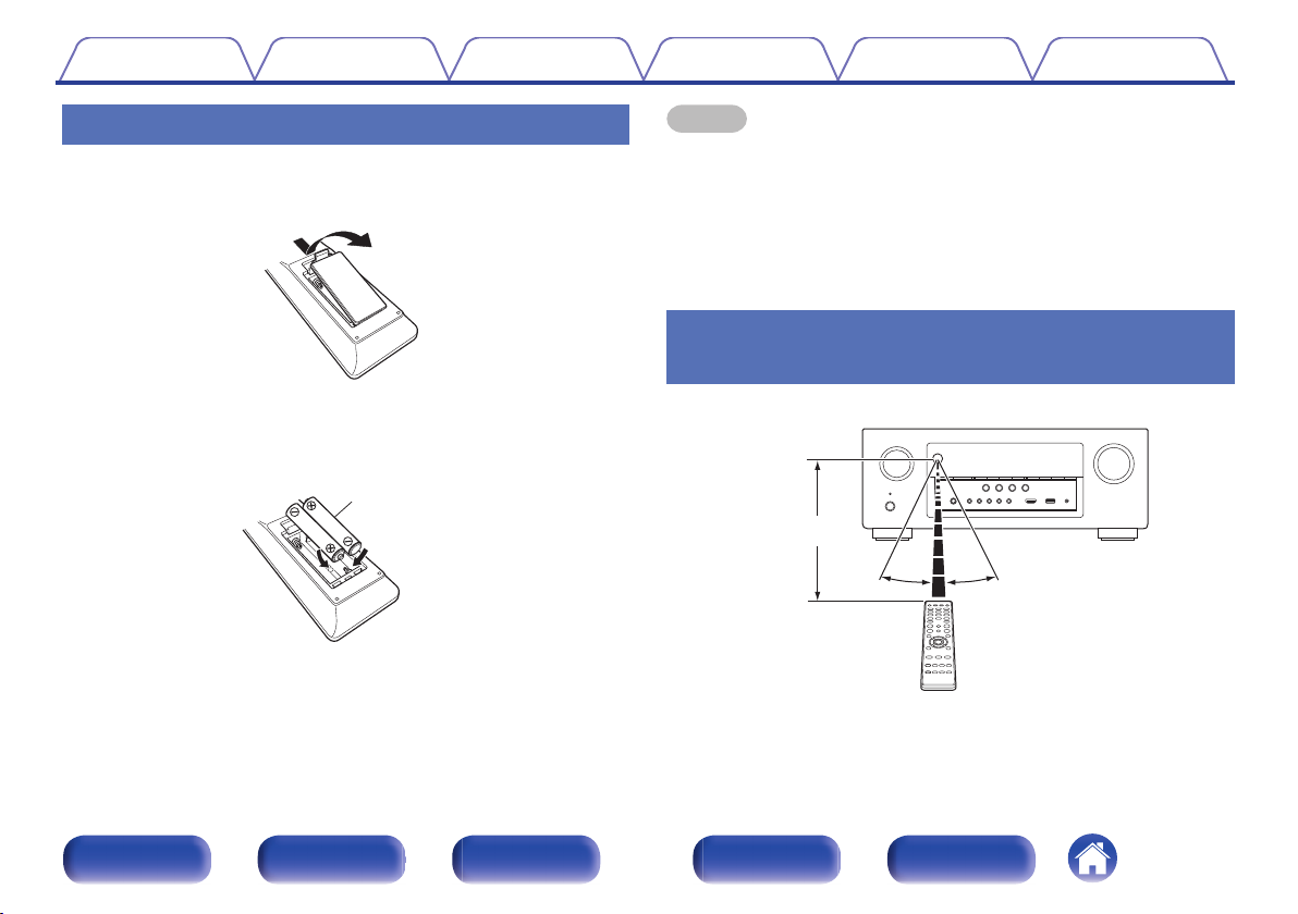
Approx. 23 ft/7 m
30° 30°
Contents Connections Playback Settings Tips Appendix
Inserting the batteries
Remove the rear lid in the direction of the arrow and
1
remove it.
.
Insert two batteries correctly into the battery
2
compartment as indicated.
.
Put the rear cover back on.
3
NOTE
To prevent damage or leakage of battery fluid:
0
Do not use a new battery together with an old one.
0
Do not use two different types of batteries.
0
Remove the batteries from the remote control unit if it will not be in use for long
0
periods.
If the battery fluid should leak, carefully wipe the fluid off the inside of the battery
0
compartment and insert new batteries.
Operating range of the remote control
unit
Point the remote control unit at the remote sensor when operating it.
.
Front panel Display Rear panel Remote Index
8
Page 9
4K 60p
4:4:4
4K 60p
4:4:4
Contents Connections Playback Settings Tips Appendix
Features
High quality sound
With discrete circuit technology, the power amplifier provides
0
identical quality for all 7-channels (125 Watts x 7-channels)
For optimum realism and stunning dynamic range, the power amplifier
section features discrete power devices (not integrated circuitry).
By using high current, high power discrete power devices, the amplifier
is able to easily drive high quality speakers.
High performance
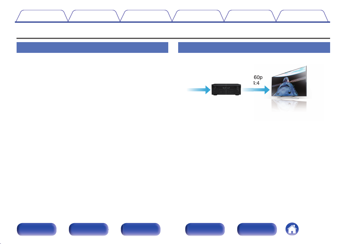
4K 60Hz input/output supported
0
.
When 4K Ultra HD (High Definition) is used, an input/output speed of 60
frames per second (60p) is achieved for video signals. When connected
to 4K Ultra HD and 60p video signal input compatible TV, you can enjoy
the sense of realism only available from high-definition images, even
when viewing fast-moving video.
This unit also supports image processing for 4K 60p, 4:4:4 and 24-bit
videos. By processing the video at the original resolution, this unit lets
you enjoy flawless, high-definition picture quality.
Front panel Display Rear panel Remote Index
9
Page 10
4K 60p
4:4:4
4K 60p
4:4:4
82
/
In Out
Contents Connections Playback Settings Tips Appendix
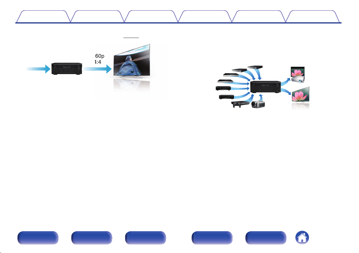
Digital video processor upscales analog video signals (SD
0
resolution) to HD (720p/1080p) and 4K (v p. 222)
.
This unit is equipped with a 4K video upscaling function that allows
analog video or SD (Standard Definition) video to be output via HDMI at
4K (3840 × 2160 pixels) resolution. This function enables the device to
be connected to a TV using a single HDMI cable, and produces high
definition images for any video source.
HDMI connections enable connection to various digital AV
0
devices (8 inputs, 2 outputs)
.
This unit is equipped with 8 HDMI inputs and 2 HDMI outputs enabling
connection to various HDMI compatible devices such as Blu-ray Disc
players, game consoles and HD video camcorders. This unit is
equipped with 2 monitor outputs, enabling you to project the same
image at the same time using this unit.
Front panel Display Rear panel Remote Index
10
Page 11
Contents Connections Playback Settings Tips Appendix
0
The device is equipped with a AirPlay® function in addition to
network functions such as Internet radio etc.
.
(v
p. 97)
You can enjoy a wide variety of content, including listening to Internet
Radio, playing audio files stored on your PC, and displaying
photographs stored on your PC on our television.
This unit also supports Apple AirPlay which lets you stream your music
library from an iPhone®, iPad®, iPod touch® or iTunes®.
Playback of DSD and FLAC files via USB and networks
0
This unit supports the playback of high resolution audio formats such as
DSD (2.8 MHz) and FLAC 192 kHz files. It provides high quality
playback of high resolution files.
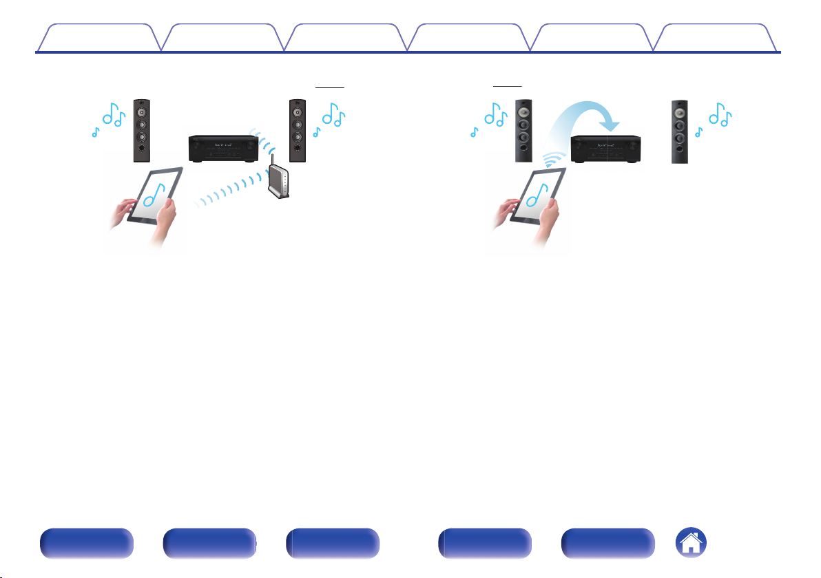
Wireless connection with Bluetooth devices can be carried out
0
easily
(v
.
p. 62)
You can enjoy music simply by connecting wirelessly with your
smartphone, tablet, PC, etc.
0
Compatible with the “Denon Remote App”z
for performing basic
operations of the unit with an iPad, iPhone or Android™ devices
(Google, Amazon Kindle Fire)
“Denon Remote App” is application software that allows you to perform
basic operations with an iPad, iPhone, Android smartphone or Android
tablet such as turning the unit ON/OFF, controlling the volume, and
switching the source.
Download the appropriate “Denon Remote App” for your iOS or Android
z
devices. This unit needs to be connected to the same LAN or Wi-Fi (wireless
LAN) network that the iPhone or iPod touch is connected to.
Front panel Display Rear panel Remote Index
11
Page 12
GMAIN ZONEHGZONE2H
Contents Connections Playback Settings Tips Appendix
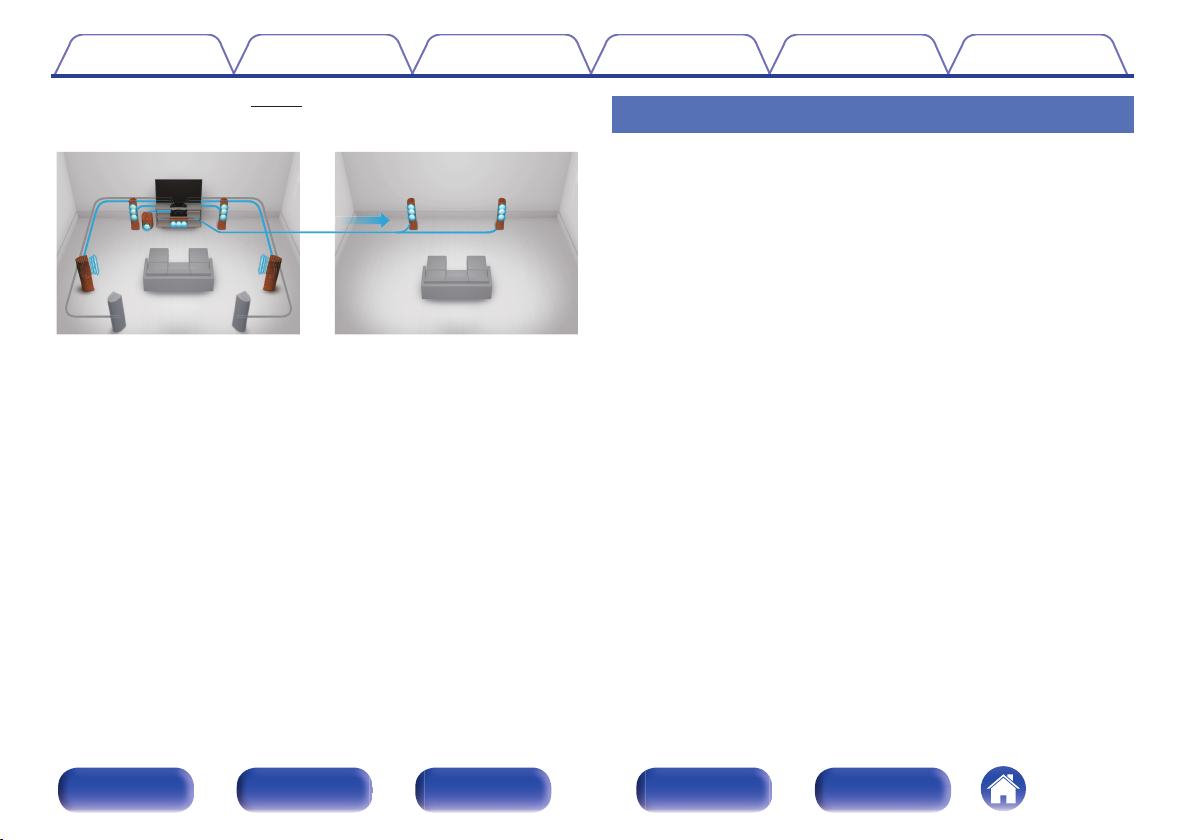
Multi-Room audio
0
.
(v
p. 111)
You can select and playback the respective inputs in the MAIN ZONE
and in ZONE2.
In addition, when the All Zone Stereo function is used, the music being
played back in the MAIN ZONE can be enjoyed in all the zones at the
same time, which is useful when you want to hear BGM throughout the
whole house.
Energy-saving design
0
This unit is equipped with an ECO Mode function that allows you to
enjoy music and movies while reducing the power consumption during
use, and also an auto-standby function that automatically turns off the
power supply when the unit is not in use. This helps reduce
unnecessary power use.
Easy operation
“Setup Assistant” provides easy-to-follow setup instructions
0
First select the language when prompted. Then simply follow the
instructions displayed on the TV screen to set up the speakers, network,
etc.
Easy to use Graphical User Interface
0
This unit is equipped with a Graphical User Interface for improved
operability.
Front panel Display Rear panel Remote Index
12
Page 13
SETUP MICAUX1 - HDMI
MASTER VOLUME
BAND MODE DIMMER STATUS
TUNEZONE2 ON/OFF ZONE2 SOURCE
TUNER
PRESET CH
PHONES
MOVIEINFO MUSIC GAME PURE
CBL/SAT
Blu-ray
23
4
ONLINE
1
QUICK SELECT
SOUND MODE
GAME
SOURCE SELECT
W1Q9Q8Q7 W0Q5 Q6
treq w y
Q0 Q1oi Q2 Q4Q3u
Contents Connections Playback Settings Tips Appendix
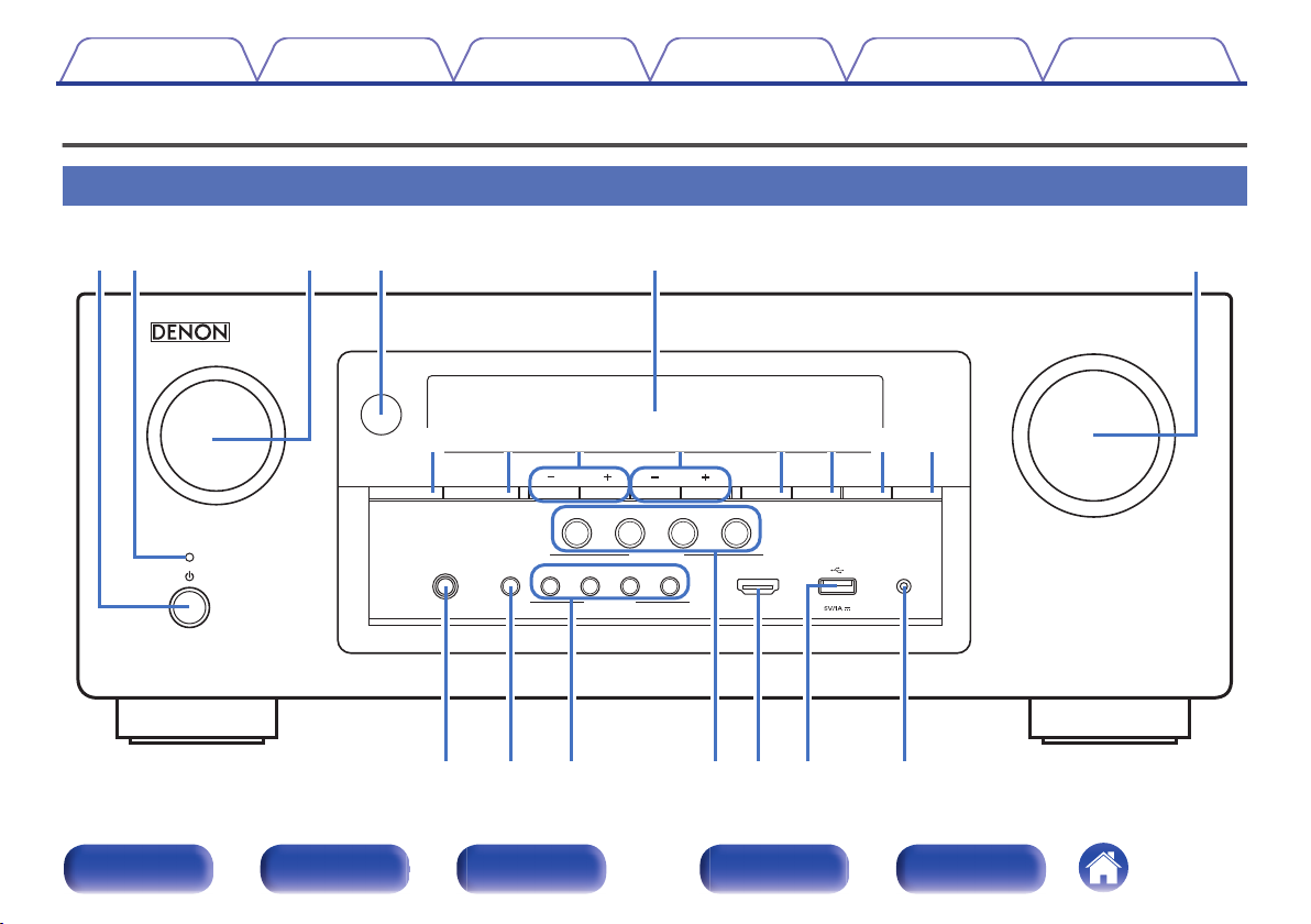
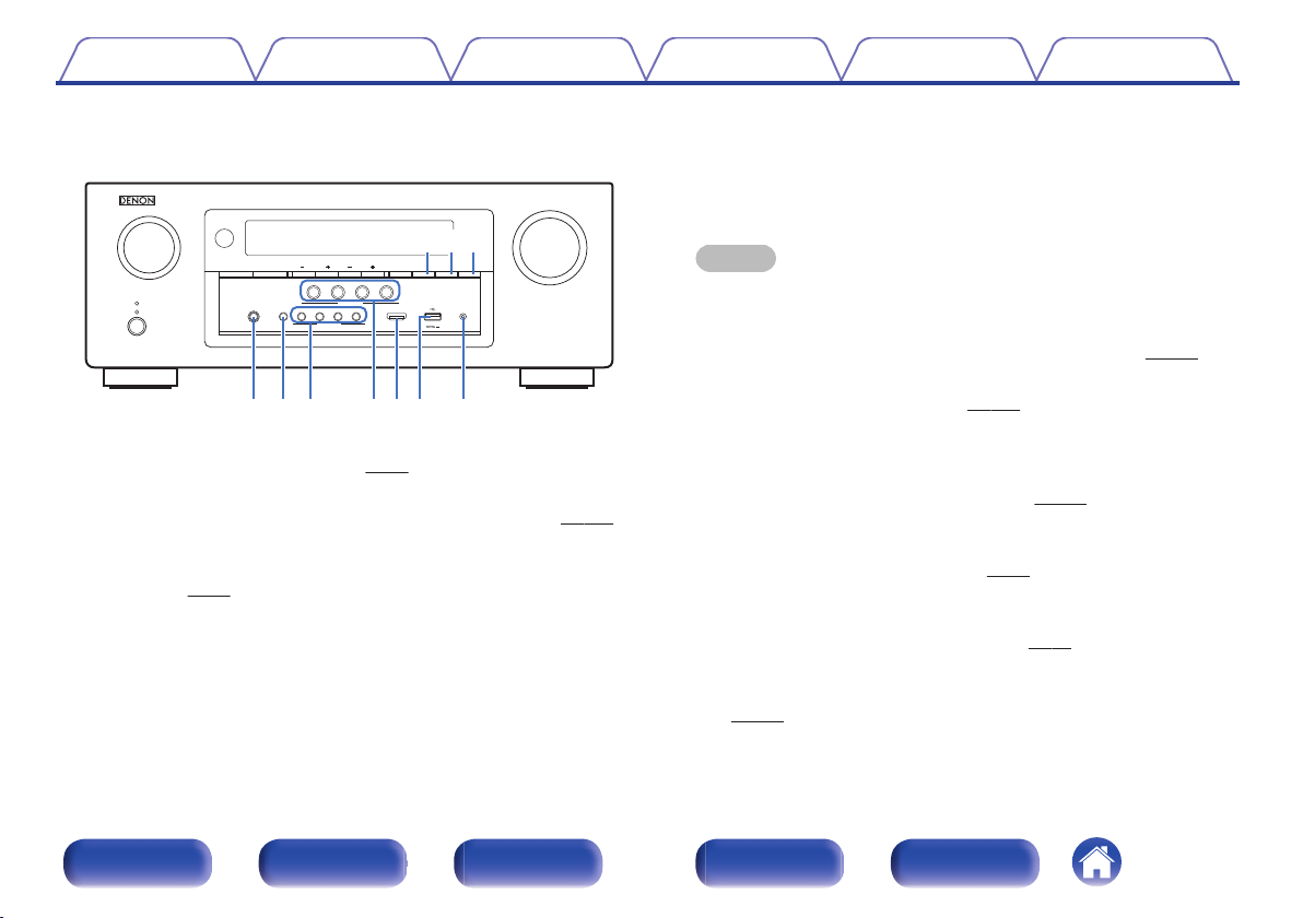
Part names and functions
Front panel
A B C D E
G
H I J K L M N
.
O P Q R S T U
Front panel Display Rear panel Remote Index
13
F
Page 14
SETUP MICAUX1 - HDMI
MASTER VOLUME
BAND MODE DIMMER STATUS
TUNEZONE2 ON/OFF ZONE2 SOURCE
TUNER
PRESET CH
PHONES
MOVIEINFO MUSIC GAME PURE
CBL/SAT
Blu-ray
23
4
ONLINE
1
QUICK SELECT
SOUND MODE
GAME
SOURCE SELECT
rqw e
u
i o Q0 Q1
ty
Contents Connections Playback Settings Tips Appendix
SOURCE SELECT knob
C
This selects the input source. (v p. 52)
Remote control sensor
D
This receives signals from the remote control unit.
Display
E
p. 53)
(v p. 16)
(v
p. 68)
p. 71)
.
Power operation button (X)
A
Used to turn the power of the MAIN ZONE (room where this unit is
located) on/off (standby). (v
Power indicator
B
p. 52)
This is lit as follows according to the power status:
Green : Power on
0
Off: Normal standby
0
Red:
0
0
When “HDMI Pass Through” (v
0
When “HDMI Control” (v p. 156) is set to “On”
0
When “IP Control” (v p. 189) is set to “Always On”
p. 156) is set to “On”
This displays various pieces of information.
MASTER VOLUME knob
F
This adjusts the volume level.
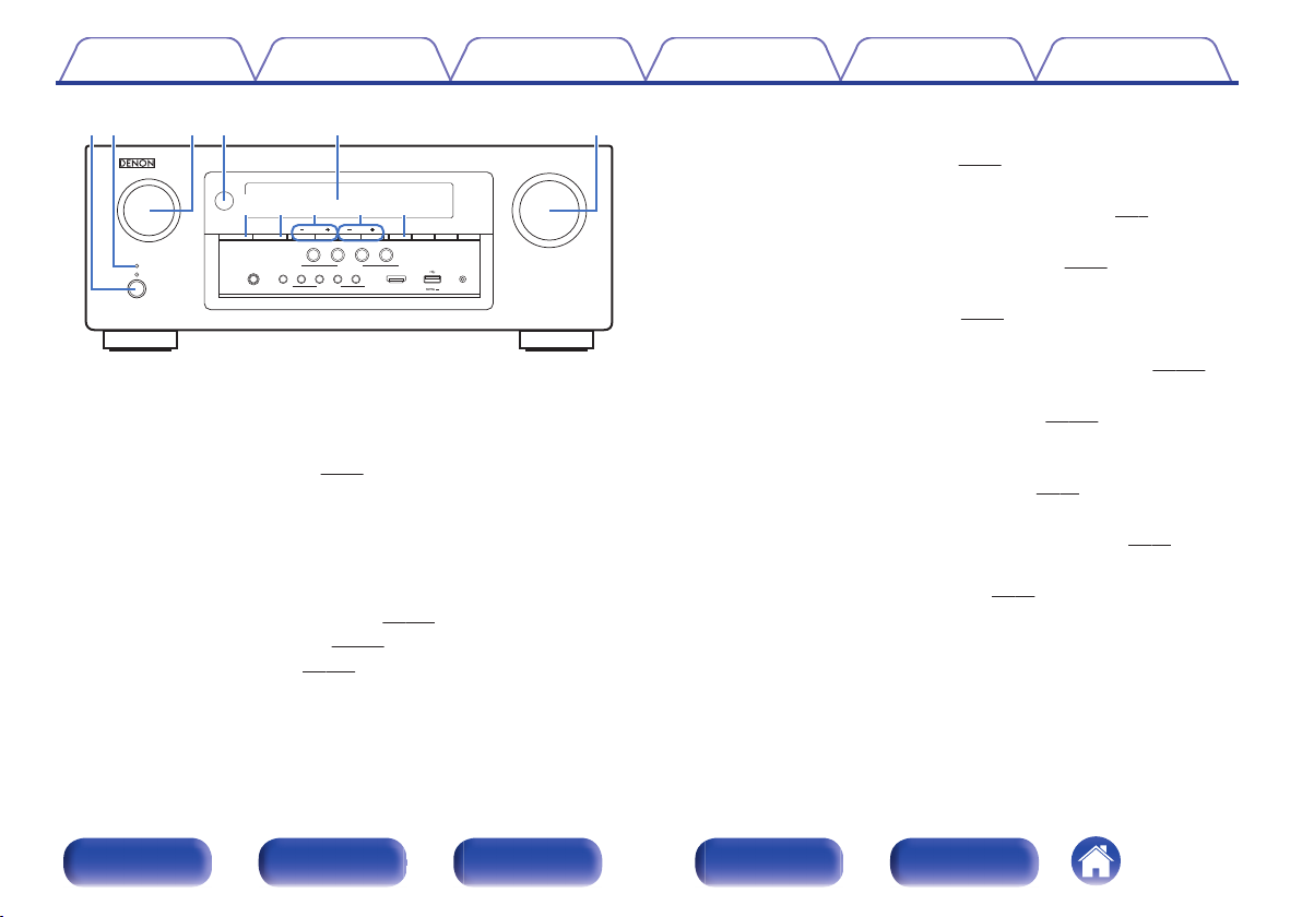
ZONE2 ON/OFF button
G
(v
This turns the power of ZONE2 (separate room) on/off. (v
ZONE2 SOURCE button
H
This selects the input source for ZONE2. (v
Tuner preset channel buttons
I
(TUNER PRESET CH +, –)
These select preset broadcast stations.
Tuning up / Tuning down buttons (TUNE +, –)
J
These select either FM broadcast or AM broadcast.
Reception band select button (BAND)
K
This switches the reception band. (v
(v
p. 133)
(v
p. 8)
p. 133)
p. 68)
Front panel Display Rear panel Remote Index
14
Page 15
SETUP MICAUX1 - HDMI
MASTER VOLUME
BAND MODE DIMMER STATUS
TUNEZONE2 ON/OFF ZONE2 SOURCE
TUNER
PRESET CH
PHONES
MOVIEINFO MUSIC GAME PURE
CBL/SAT
Blu-ray
23
4
ONLINE
1
QUICK SELECT
SOUND MODE
GAME
SOURCE SELECT
Q
9Q8
Q
7
Q5Q
6
Q2 Q4
W
1
Q3
W
0
Contents Connections Playback Settings Tips Appendix
Headphones jack (PHONES)
O
This is used to connect headphones.
When the headphones are plugged into this jack, audio will no longer
be output from the connected speakers or from the SUBWOOFER
connectors.
NOTE
To prevent hearing loss, do not raise the volume level excessively when using
headphones.
Information button (INFO)
P
This displays the status information on the TV screen.
SOUND MODE buttons
Q
p. 112)
.
Tune mode select button (MODE)
L
This switches the tuning mode. (v
DIMMER button
M
p. 70)
Each press of this switches the brightness of the display. (v p. 195)
STATUS button
N
Each press of this switches the status information that is shown on the
(v
display.
p. 56)
These select the sound mode.
QUICK SELECT buttons
R
With a single press of any of these buttons, you can call up various
settings you’ve registered to each button such as the input source,
volume level and sound mode settings.
AUX1-HDMI connector
S
This is used to connect HDMI output compatible devices such as video
camcorders and game consoles.
USB port
T
This is used to connect USB storages (such as USB memory devices)
and the USB cable supplied with iPod.
SETUP MIC jack
U
This is used to connect the supplied Sound calibration microphone.
(v
p. 171)
(v
(v
(v
p. 43)
(v
p. 127)
p. 44)
(v
p. 196)
Front panel Display Rear panel Remote Index
15
Page 16
iouytrewq
Q
0
Q1Q
2
Contents Connections Playback Settings Tips Appendix
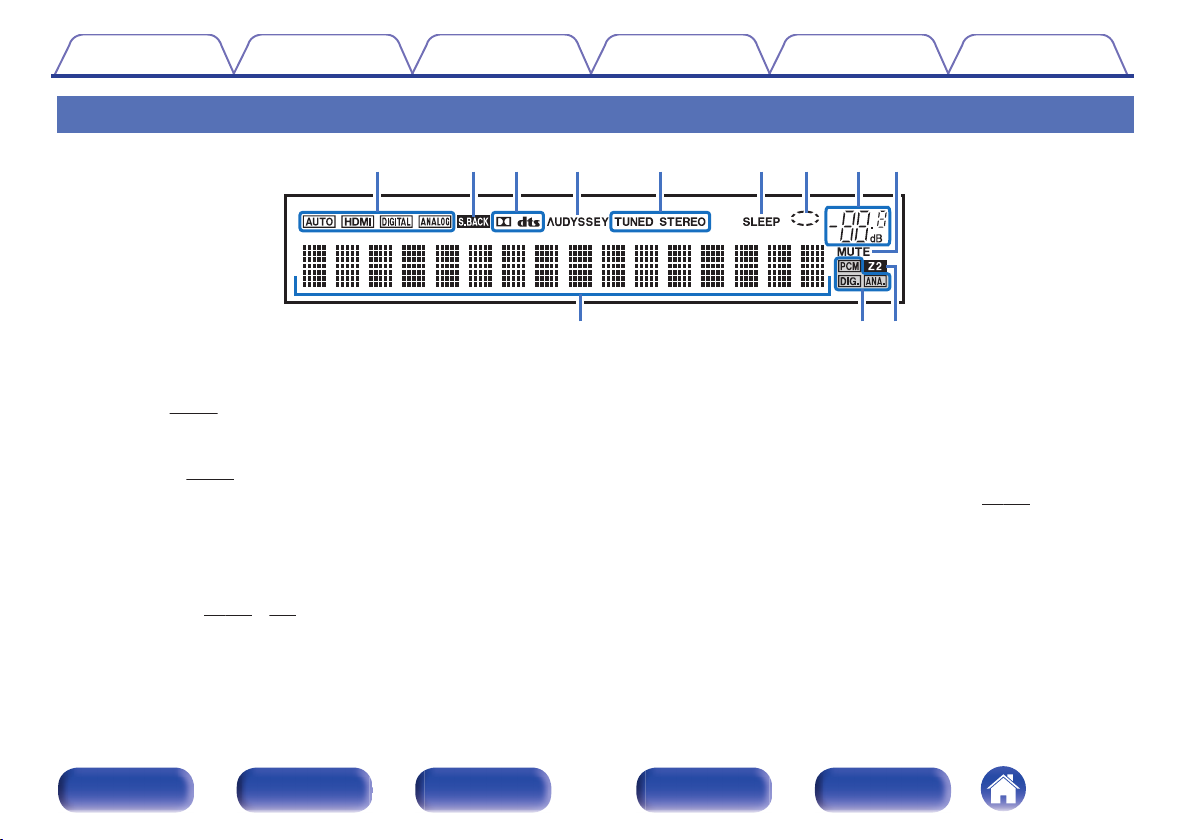
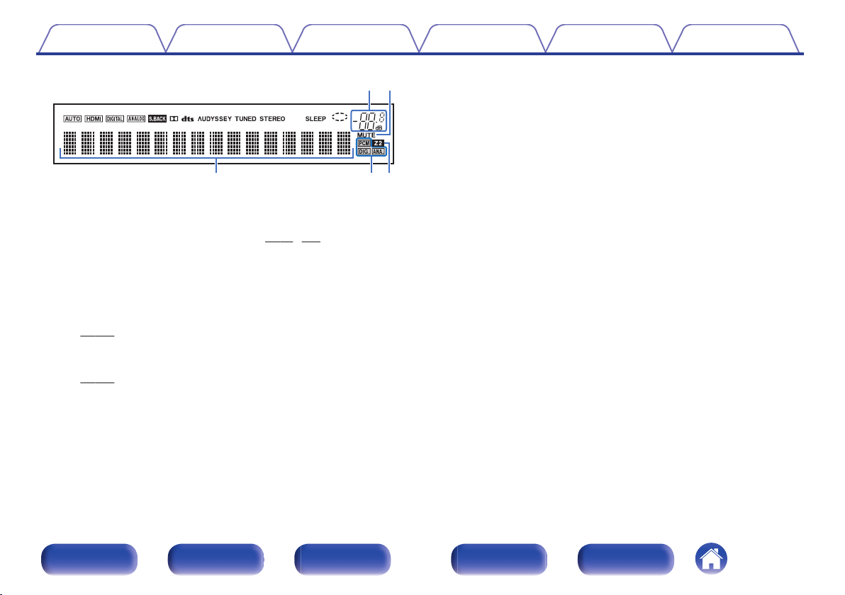
Display
H I
.
Input mode indicators
A
These light according to the audio input mode settings of each input
(v
source.
Surround back indicator
B
This lights when audio signals are being output from the surround back
speakers. (v p. 180)
Decoder indicators
C
These light when Dolby or DTS signals are input or when the Dolby or
DTS decoder is running.
D
Audyssey® indicator
This lights when “MultEQ®”, “Dynamic EQ” or “Dynamic Volume” has
been set up. (v
p. 167)
p. 148 - 150)
J K L
Tuner reception mode indicators
E
These light up according to the reception conditions when the input
source is set to “Tuner”.
TUNED: Lights up when the broadcast is properly tuned in.
STEREO: Lights up when receiving FM stereo broadcasts.
Sleep timer indicator
F
This lights when the sleep mode is selected.
Circle indicator
G
This is displayed when the input source is “Online Music” or “iPod/USB”
when you are playing back music.
Front panel Display Rear panel Remote Index
16
(v
p. 126)
Page 17
io
Q
2Q1
Q
0
Contents Connections Playback Settings Tips Appendix
.
Volume indicator
H
MUTE indicator
I
p. 53, 134)
This blinks while the sound is muted.
Information display
J
The input source name, sound mode, setting values and other
information are displayed here.
Input signal indicators
K
The respective indicator will light corresponding to the input signal.
(v
p. 167)
ZONE2 indicator
L
This lights up when ZONE2 (separate room) power is turned on.
(v p. 133)
(v
Front panel Display Rear panel Remote Index
17
Page 18
SPEAKERS
IMPEDANCE : 4㹼16ȐCLASS 2 WIRING
AM
NETWORK
(ASSIGNABLE)
HDMI
PRE OUT
ANTENNA
2
1
1
CBL/
SAT
2
DVD
3
Blu-ray
6
AUX2
7
CD
4
GAME
5
MEDIA
PLAYER
ARC
MONITOR1
MONITOR2
3
Blu-ray
4
CD
2
DVD
1
CBL/
SAT
1 CBL/SAT
CBL/SAT
COAXIAL
OPTICAL
1
CBL/SAT
2
DVD
(ASSIGNABLE)
VIDEO
2 DVD
COMPONENT VIDEO
1
TV
AUDIO
2
CD
(ASSIGNABLE)
COMPONENT VIDEO
SUBWOOFER
PR
/
CR
PB
/
CB
Y
MONITOR
PR
/
CR
PB
/
CB
Y
PR
/
CR
PB
/
CB
Y
(ASSIGNABLE)
AUDIO
HDMI
(ASSIGNABLE)
DIGITAL AUDIO
y qqte rw
ui Q
1
Q
0
o
Contents Connections Playback Settings Tips Appendix
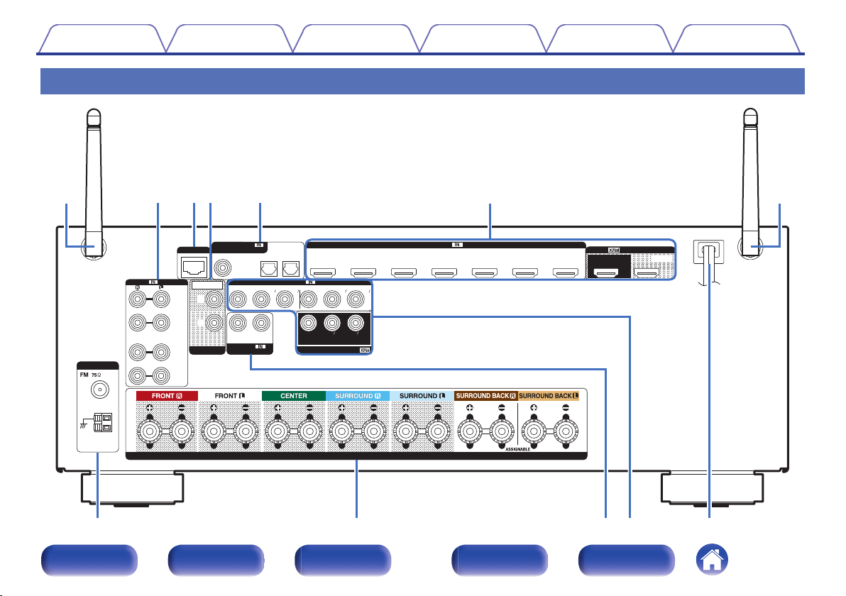
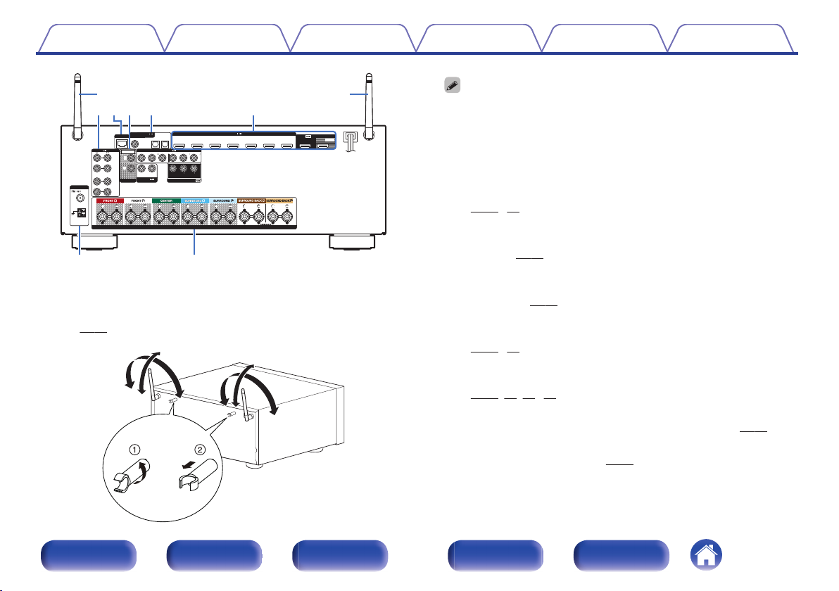
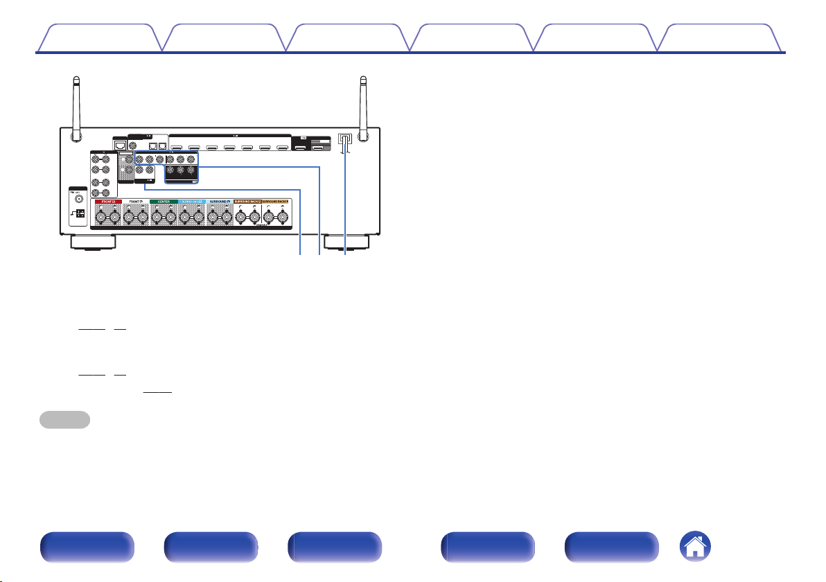
Rear panel
A B CD E F A
G H
.
Front panel Display Rear panel Remote Index
18
I J K
Page 19
SPEAKERS
IMPEDANCE : 4㹼16ȐCLASS 2 WIRING
AM
NETWORK
(ASSIGNABLE)
HDMI
PRE OUT
ANTENNA
2
1
1
CBL/
SAT
2
DVD
3
Blu-ray
6
AUX2
7
CD
4
GAME
5
MEDIA
PLAYER
ARC
MONITOR1
MONITOR2
3
Blu-ray
4
CD
2
DVD
1
CBL/
SAT
1 CBL/SAT
CBL/SAT
COAXIAL
OPTICAL
1
CBL/SAT
2
DVD
(ASSIGNABLE)
VIDEO
2 DVD
COMPONENT VIDEO
1
TV
AUDIO
2
CD
(ASSIGNABLE)
COMPONENT VIDEO
SUBWOOFER
PR
/
CR
PB
/
CB
Y
MONITOR
PR
/
CR
PB
/
CB
Y
PR
/
CR
PB
/
CB
Y
(ASSIGNABLE)
AUDIO
HDMI
(ASSIGNABLE)
DIGITAL AUDIO
ytrw e
ui
qq
90°
320°
320°
90°
Contents Connections Playback Settings Tips Appendix
The antenna clip can be removed from the rear panel.
Rotate the antenna clip 90 degrees to the left.
A
Pull the antenna clip out towards yourself.
B
The antenna clip is needed when transporting this unit. Keep it in a safe place.
0
Attach the antenna clip by following the steps for removing it in reverse.
0
Analog audio connectors (AUDIO)
B
Used to connect devices equipped with analog audio connectors.
(v
p. 41, 42)
NETWORK connector
C
Used to connect to a LAN cable when connecting to a wired LAN
.
Rod antennas for Bluetooth/wireless LAN
A
Stand this antenna upright when connecting to a network via wireless
LAN, or when connecting to a handheld device via Bluetooth.
(v p. 49)
network.
PRE OUT connectors
D
Used to connect a subwoofer with built-in amplifier or power amplifier
for ZONE2.
Digital audio connectors (DIGITAL AUDIO)
E
Used to connect devices equipped with digital audio connectors.
(v p. 38, 42)
HDMI connectors
F
Used to connect devices equipped with HDMI connectors.
.
Front panel Display Rear panel Remote Index
(v
FM/AM antenna terminals (ANTENNA)
G
Used to connect FM antennas and AM loop antennas. (v
Speaker terminals (SPEAKERS)
H
Used to connect speakers.
19
(v
p. 48)
(v
p. 29)
p. 37, 38, 41, 42)
(v
p. 28)
p. 46)
Page 20
SPEAKERS
IMPEDANCE : 4㹼16ȐCLASS 2 WIRING
AM
NETWORK
(ASSIGNABLE)
HDMI
PRE OUT
ANTENNA
2
1
1
CBL/
SAT
2
DVD
3
Blu-ray
6
AUX2
7
CD
4
GAME
5
MEDIA
PLAYER
ARC
MONITOR1
MONITOR2
3
Blu-ray
4
CD
2
DVD
1
CBL/
SAT
1 CBL/SAT
CBL/SAT
COAXIAL
OPTICAL
1
CBL/SAT
2
DVD
(ASSIGNABLE)
VIDEO
2 DVD
COMPONENT VIDEO
1
TV
AUDIO
2
CD
(ASSIGNABLE)
COMPONENT VIDEO
SUBWOOFER
PR
/
CR
PB
/
CB
Y
MONITOR
PR
/
CR
PB
/
CB
Y
PR
/
CR
PB
/
CB
Y
(ASSIGNABLE)
AUDIO
HDMI
(ASSIGNABLE)
DIGITAL AUDIO
Q
1Q0
o
Contents Connections Playback Settings Tips Appendix
.
Video connectors (VIDEO)
I
Used to connect devices equipped with video connectors.
(v
p. 41, 42)
Component video connectors (COMPONENT VIDEO)
J
Used to connect devices equipped with component video connectors.
(v p. 41, 42)
Power cord
K
(v
p. 50)
NOTE
Do not touch the inner pins of the connectors on the rear panel. Electrostatic
discharge may cause permanent damage to the unit.
Front panel Display Rear panel Remote Index
20
Page 21
q
w
e
t
r
u
y
Contents Connections Playback Settings Tips Appendix
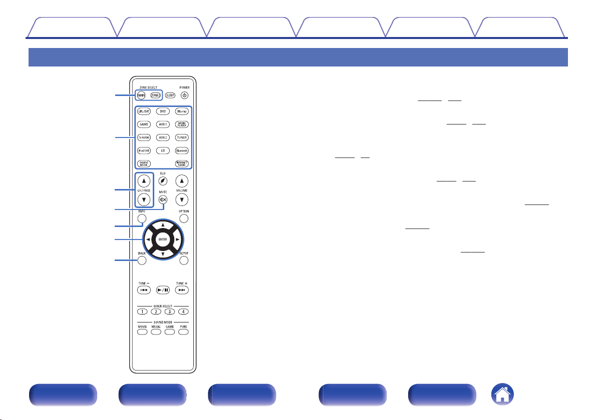
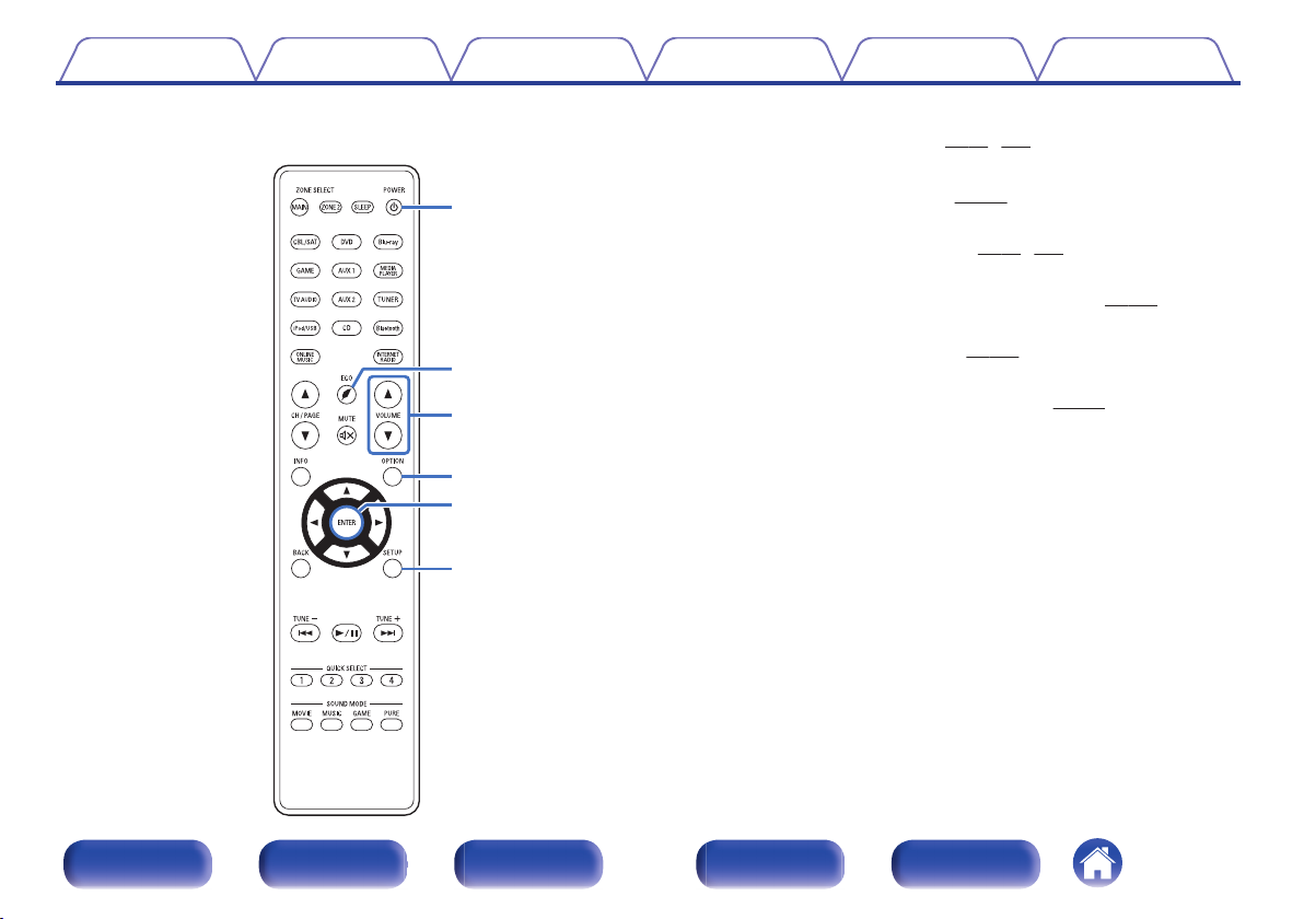
Remote control unit
ZONE SELECT buttons (MAIN, ZONE2)
A
These switch the zone (MAIN ZONE, ZONE2) that is operated through
the remote control unit.
Input source select buttons
B
These selects the input source. (v
Channel/page select buttons (CH/PAGE df)
C
These select radio stations registered to presets or switch pages.
(v
p. 56, 71)
MUTE button (:)
D
This mutes the output audio. (v
Information button (INFO)
E
This displays the status information on the TV screen.
Cursor buttons (uio p)
F
These select items.
BACK button
G
This returns to the previous screen.
(v
(v
p. 133, 138)
p. 138)
p. 52, 133)
p. 53, 134)
(v
p. 138)
(v
p. 196)
.
Front panel Display Rear panel Remote Index
21
Page 22
Q0
o
Q2
Q1
i
Contents Connections Playback Settings Tips Appendix
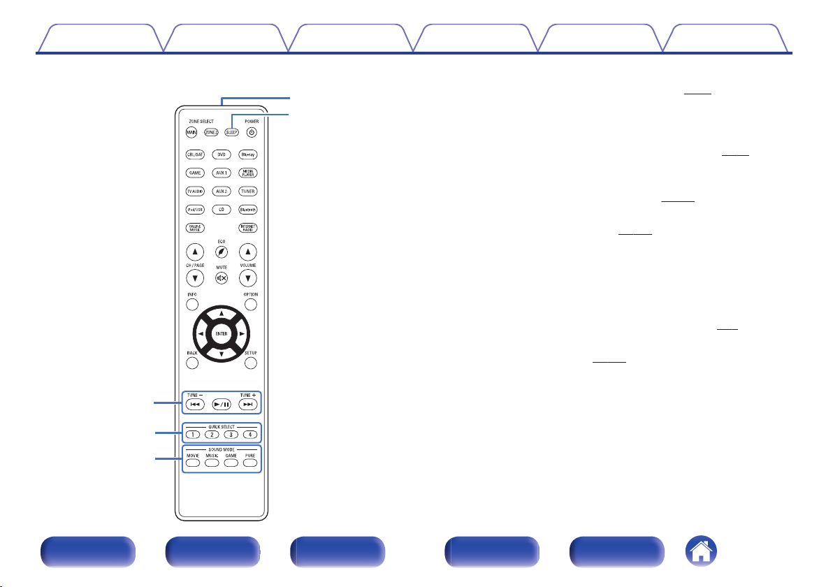
System buttons
H
These perform playback related operations.
Skip buttons (8, 9)
0
Play/pause button (1/3)
0
(v
p. 56)
Tuning up / Tuning down buttons (TUNE +, –)
(v
These select either FM broadcast or AM broadcast.
QUICK SELECT buttons (1 – 4)
I
p. 68)
These call up settings registered to each button, such as input source,
volume level and sound mode settings. (v p. 127)
SOUND MODE buttons
J
These select the sound mode. (v p. 112)
MOVIE button
0
MUSIC button
0
GAME button
0
PURE button
0
Remote control signal transmitter
K
This transmits signals from the remote control unit. (v
SLEEP button
L
p. 125)
This sets the sleep timer.
(v
p. 8)
.
Front panel Display Rear panel Remote Index
22
Page 23
Q3
Q5
Q4
Q8
Q6
Q7
Contents Connections Playback Settings Tips Appendix
POWER button (X)
M
This turns the power on/off.
N
ECO Mode button (G)
This switches to ECO Mode.
VOLUME buttons (df)
O
These adjusts the volume level.
OPTION button
P
This displays the option menu on the TV screen.
ENTER button
Q
This determines the selection.
SETUP button
R
This displays the menu on the TV screen.
(v
(v
(v
(v
p. 52, 133)
p. 191)
p. 53, 134)
p. 138)
(v
(v
p. 138)
p. 101)
.
Front panel Display Rear panel Remote Index
23
Page 24
R
L
R
L
Contents Connections Playback Settings Tips Appendix
Connections
Contents
o
Connecting speakers 25
Connecting a TV 36
Connecting a playback device 40
Connecting an iPod or USB memory device to the USB port 44
Connecting an FM/AM antenna 46
Connecting to a home network (LAN) 48
Connecting the power cord 50
NOTE
Do not plug in the power cord until all connections have been completed.
0
However, when the “Setup Assistant” is running, follow the instructions in the
“Setup Assistant” (page 8 in the separate “Quick Start Guide”) screen for making
connections. (During “Setup Assistant” operation, the input/output connectors do
not conduct current.)
Do not bundle power cords together with connection cables. Doing so can result in
0
noise.
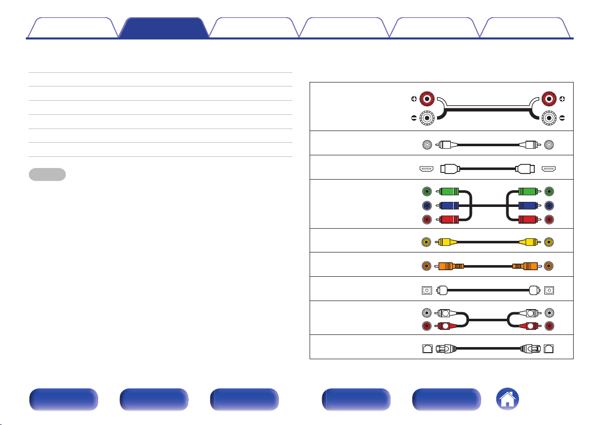
Cables used for connections
o
Provide necessary cables according to the devices you want to
connect.
Speaker cable
.
Subwoofer cable
HDMI cable
.
.
Component video cable
.
Video cable
Coaxial digital cable
Optical cable
.
.
.
Audio cable
.
LAN cable
Front panel Display Rear panel Remote Index
24
.
Page 25
FHL
FL
SW1
C
SL
SBL
FHR
FR
SR
SBR
SB
SW2
Contents Connections Playback Settings Tips Appendix
Connecting speakers
Install speakers and connect them to this unit. (v p. 25, 28)
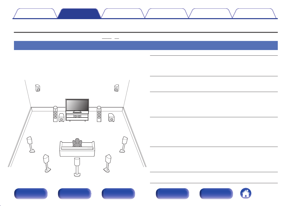
Speaker installation
Determine the speaker system depending on the number of speakers you
are using and install each speaker and subwoofer in the room.
Speaker installation is explained using this example of a typical
installation.
.
Front panel Display Rear panel Remote Index
FL/FR (Front
speaker left/right):
C (Center
speaker):
SL/SR (Surround
speaker left/right):
SBL/SBR
(Surround back
speaker left/right):
FHL/FHR (Front
height speakers
left/right):
SW 1/2 (Subwoofer) :
25
Place the FRONT left and right speakers an
equal distance from the main listening position.
The distance between each speaker and your TV
should also be the same.
Place the CENTER speaker in front of and at the
center of the TV, between the front left and right
speakers.
Place the SURROUND left and right speakers an
equal distance to the left and right sides of the
main listening position. If you don’t have
surround back speakers, move the surround
speakers slightly behind your listening position.
Place the SURROUND BACK left and right
speakers an equal distance from the main
listening position and directly behind the main
listening position. When using a single surround
back speaker (SB), place it directly behind the
listening position.
Place the FRONT HEIGHT left and right
speakers just outside of the front left and right
speakers. Mount them as close to the ceiling as
possible and aim them towards the listening
position.
Place the SUBWOOFER at a convenient location
near the front speakers.
Page 26
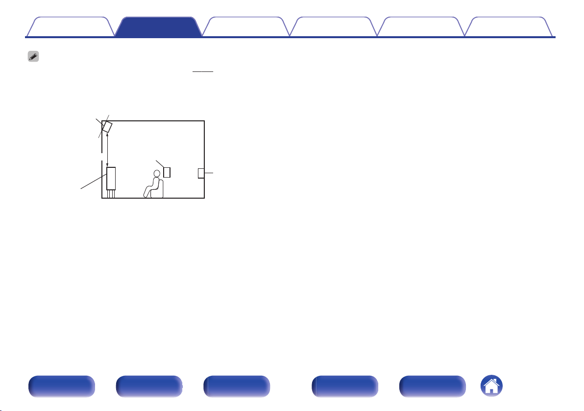
z
Surround back
speaker
At least 3.3 ft / 1 m
Front height
speaker
Point slightly
downwards
Surround
speaker
Front speaker
GViewed from the sideH
z Recommended for Dolby Pro Logic gz
Contents Connections Playback Settings Tips Appendix
This unit is compatible with Dolby Pro Logic gz (v p. 240) which offers an even
0
wider and deeper surround sensation.
When using Dolby Pro Logic gz, install front height speakers.
Use the illustration below as a guide for how high each speaker should be
0
installed. The height does not need to be exactly the same.
.
Front panel Display Rear panel Remote Index
26
Page 27
z1
z2
z3
FL
SW
C
SL
SBL
FR
SR
SBR
Listening
position
z1
z2
z3
FHL FHR
FL
SW
C
SL
FR
SR
z1
z2
FL
SW
C
SL
FR
SR
Contents Connections Playback Settings Tips Appendix
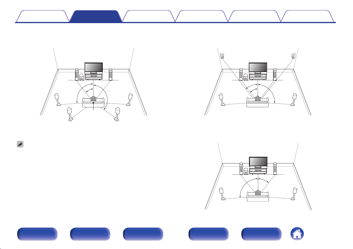
When 7.1-channel speakers are installed using
o
surround back speakers
.
z
1:22° - 30° z2:90° - 110° z3:135° - 150°
When using a single surround back speaker, place it directly behind the listening
position.
When 7.1-channel speakers are installed using
o
front height speakers
.
z
1:22° - 30° z2:22° - 45° z3:90° - 110°
When 5.1-channel speakers are installed
o
Front panel Display Rear panel Remote Index
27
.
z
1:22° - 30° z2:120°
Page 28
Contents Connections Playback Settings Tips Appendix
Speaker connection
Here we connect the speakers in the room to this unit.
This section explains how to connect them using typical examples.
NOTE
Disconnect this unit’s power plug from the power outlet before connecting the
0
speakers. Also, turn off the subwoofer.
Connect so that the speaker cable core wires do not protrude from the speaker
0
terminal. The protection circuit may be activated if the core wires touch the rear
panel or if the + and - sides touch each other. (“Protection circuit” (v p. 248))
Never touch the speaker terminals while the power cord is connected. Doing so
0
could result in electric shock. When the “Setup Assistant” (page 8 in the separate
“Quick Start Guide”) is running, follow the instructions in the “Setup Assistant”
screen for making connections. (Power is not supplied to the speaker terminals
while the “Setup Assistant” is running.)
Use speakers with an impedance of 4 – 16 Ω/ohms.
0
NOTE
Carry out the following settings when using a speaker with an impedance of 4 – 6
0
Ω/ohms.
Press and hold the main unit’s TUNER PRESET CH + and TUNE + for at least
1.
3 seconds.
“V.Format:< NTSC>” appears on the display.
Press DIMMER on the main unit twice.
2.
“Sp.Imp.:<8ohms>” appears on the display.
Press TUNER PRESET CH + or TUNER PRESET CH - on the main unit to
3.
select the impedance.
6 Ω/ohms to 8 Ω/ohms is selected even if it is for one speaker with a
6 Ω:
connected impedance.
4 Ω/ohms to 8 Ω/ohms is selected even if it is for one speaker with a
4 Ω:
connected impedance.
Press the main unit’s STATUS to complete the setting.
4.
Front panel Display Rear panel Remote Index
28
Page 29
SPEAKERS
IMPEDANCE : 4㹼16ȐCLASS 2 WIRING
3
Blu-ray
4
CD
2
DVD
1
CBL/
SAT
1 CBL/SAT
1
CBL/SAT
2
DVD
(ASSIGNABLE)
VIDEO
2 DVD
COMPONENT VIDEO
(ASSIGNABLE)
COMPONENT VIDEO
PR
/
CR
PB
/
CB
Y
MONITOR
PR
/
CR
PB
/
CB
Y
PR
/
CR
PB
/
CB
Y
(ASSIGNABLE)
AUDIO
PRE OUT
2
1
SUBWOOFER
SW1 SW2
Contents Connections Playback Settings Tips Appendix
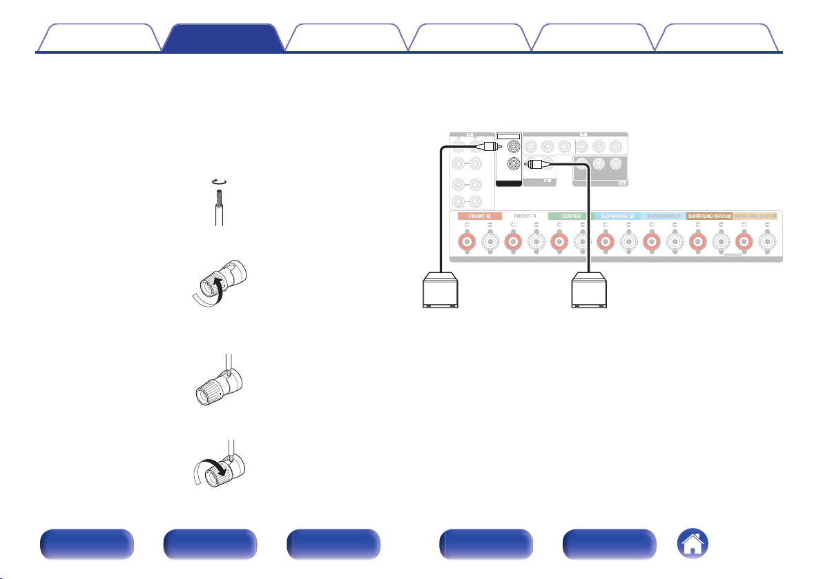
Connecting the speaker cables
o
Carefully check the left (L) and right (R) channels and + (red) and –
(black) polarities on the speakers being connected to this unit, and be
sure to connect the channels and polarities correctly.
Peel off about 3/8 inch (10 mm) of sheathing from the
1
tip of the speaker cable, then either twist the core wire
tightly or terminate it.
.
Turn the speaker terminal counterclockwise to loosen it.
2
.
Insert the speaker cable’s core wire to the hilt into the
3
speaker terminal.
Turn the speaker terminal clockwise to tighten it.
4
.
Connecting the subwoofer
o
Use a subwoofer cable to connect the subwoofer. Two subwoofers can
be connected to this unit.
The same signal is output from the respective subwoofer terminals.
.
.
Front panel Display Rear panel Remote Index
29
Page 30
Speaker
This unit
Contents Connections Playback Settings Tips Appendix
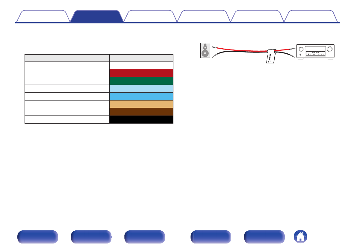
About the speaker cable label (supplied) for
o
channel identification
The channel display section for speaker terminals on the rear panel is
color-coded for each channel to be identifiable.
Speaker terminals Color
FRONT L White
FRONT R
CENTER Green
SURROUND L
SURROUND R Blue
SURROUND BACK L Beige
SURROUND BACK R
SUBWOOFER Black
Attach the speaker cable label for each channel to its speaker cable as
shown in the diagram.
Refer to the table above and attach the label to each speaker cable.
Then, make connection so that the color of the speaker terminal
matches that of the speaker cable label.
Red
Light blue
Brown
G How to attach the speaker cable label H
.
Front panel Display Rear panel Remote Index
30
Page 31

Contents Connections Playback Settings Tips Appendix
Speaker configuration and Amp Assign settings
This unit has a built-in 7-channel power amplifier. In addition to the basic 5.1-channel system, a variety of speaker systems can be configured by changing
the “Amp Assign” (v
playback.
Perform “Amp Assign” (v
5.1-channel Not used ZONE2 (Default) 32
7.1-channel (surround back) Not used Surround Back 33
7.1-channel (front height) Not used Front Height
5.1-channel 2-channel ZONE2 (Default) 35
The sound mode that can be selected varies according to the speaker configuration. See “Relationship between sound modes and channel output” (v p. 231) for the sound
modes that are supported.
p. 178) settings to suit the application, such as 7.1-channel systems, bi-amp connections and 2-channel systems for multi-zone
p. 178) settings to suit the number of rooms and speaker configuration to be installed.
Playback speaker and zone
MAIN ZONE ZONE2
“Amp Assign” settings
Connection
page
34
Front panel Display Rear panel Remote Index
31
Page 32

FL
SW C
SL
FR
SR
3
Blu-ray
4
CD
2
DVD
1
CBL/
SAT
1 CBL/SAT
1
CBL/SAT
2
DVD
(ASSIGNABLE)
VIDEO
2 DVD
COMPONENT VIDEO
(ASSIGNABLE)
COMPONENT VIDEO
PR
/
CR
PB
/
CB
Y
MONITOR
PR
/
CR
PB
/
CB
Y
PR
/
CR
PB
/
CB
Y
(ASSIGNABLE)
AUDIO
PRE OUT
2
1
SUBWOOFER
SPEAKERS
IMPEDANCE : 4㹼16ȐCLASS 2 WIRING
SLFLFR C SR
SW
Contents Connections Playback Settings Tips Appendix
Standard configuration and connection
o
n
5.1-channel
This serves as a basic 5.1-channel surround system.
Sound modes such as Dolby Pro Logic g are supported.
.
.
Front panel Display Rear panel Remote Index
32
Page 33

FL
SW
SL
FR
SR
SBRSBL
3
Blu-ray
4
CD
2
DVD
1
CBL/
SAT
1 CBL/SAT
1
CBL/SAT
2
DVD
(ASSIGNABLE)
VIDEO
2 DVD
COMPONENT VIDEO
(ASSIGNABLE)
COMPONENT VIDEO
PR
/
CR
PB
/
CB
Y
MONITOR
PR
/
CR
PB
/
CB
Y
PR
/
CR
PB
/
CB
Y
(ASSIGNABLE)
AUDIO
PRE OUT
2
1
SUBWOOFER
SPEAKERS
IMPEDANCE : 4㹼16ȐCLASS 2 WIRING
FLFR C SR SL SBR SBL
SW
Contents Connections Playback Settings Tips Appendix
n
7.1-channel (surround back)
This 7.1-channel surround system is the same as a basic 5.1-channel system but with surround back speakers.
Sound modes such as Dolby Pro Logic gx are supported.
.
.
When using a single surround back speaker, connect it to the SURROUND BACK L
terminal.
Front panel Display Rear panel Remote Index
33
Page 34

FL
SW C
SL
FHR
FR
SR
FHL
3
Blu-ray
4
CD
2
DVD
1
CBL/
SAT
1 CBL/SAT
1
CBL/SAT
2
DVD
(ASSIGNABLE)
VIDEO
2 DVD
COMPONENT VIDEO
(ASSIGNABLE)
COMPONENT VIDEO
PR
/
CR
PB
/
CB
Y
MONITOR
PR
/
CR
PB
/
CB
Y
PR
/
CR
PB
/
CB
Y
(ASSIGNABLE)
AUDIO
PRE OUT
2
1
SUBWOOFER
SPEAKERS
IMPEDANCE : 4㹼16ȐCLASS 2 WIRING
SW
FLFR C SR SL FHR FHL
Contents Connections Playback Settings Tips Appendix
n
7.1-channel (front height)
This 7.1-channel surround system is the same as a basic 5.1-channel system but with front height speakers.
Sound modes such as Dolby Pro Logic gz are supported.
.
.
Front panel Display Rear panel Remote Index
34
Page 35

FL
SW C
SL
FR
SR
ZONE2
L
ZONE2
R
3
Blu-ray
4
CD
2
DVD
1
CBL/
SAT
1 CBL/SAT
1
CBL/SAT
2
DVD
(ASSIGNABLE)
VIDEO
2 DVD
COMPONENT VIDEO
(ASSIGNABLE)
COMPONENT VIDEO
PR
/
CR
PB
/
CB
Y
MONITOR
PR
/
CR
PB
/
CB
Y
PR
/
CR
PB
/
CB
Y
(ASSIGNABLE)
AUDIO
PRE OUT
2
1
SUBWOOFER
SPEAKERS
IMPEDANCE : 4㹼16ȐCLASS 2 WIRING
FLFR C SR SL
SW
ZONE2RZONE2
L
Contents Connections Playback Settings Tips Appendix
n
5.1-channel (MAIN ZONE) + 2-channel (ZONE2)
This connection method constructs a 5.1-channel speaker system in the MAIN ZONE and a 2-channel system in ZONE2.
MAIN ZONE
.
ZONE2
.
.
Front panel Display Rear panel Remote Index
35
Page 36

Is the TV equipped with an HDMI connector?
Is the TV compatible with the ARC (Audio Return Channel) ?
Yes
Yes No
No
Contents Connections Playback Settings Tips Appendix
Connecting a TV
Connect a TV to this unit so that the input video is output to the TV. You can also enjoy audio from the TV on this unit.
How to connect a TV depends on the connectors and functions equipped on the TV.
ARC (Audio Return Channel) function plays TV audio on this unit by sending the TV audio signal to this unit via HDMI cable.
.
“Connection 1 : TV equipped with an HDMI
connector and compatible with the ARC (Audio
Return Channel)” (v p. 37)
“Connection 2 : TV equipped with an HDMI
connector and incompatible with the ARC (Audio
Return Channel)” (v p. 38)
“Connection 3 : TV equipped without
an HDMI connector” (v p. 39)
Front panel Display Rear panel Remote Index
36
Page 37

AM
NETWORK
(ASSIGNABLE)
HDMI
PRE OUT
ANTENNA
2
1
1
CBL/
SAT
2
DVD
3
Blu-ray
6
AUX2
7
CD
4
GAME
5
MEDIA
PLAYER
3
Blu-ray
4
CD
2
DVD
1
CBL/
SAT
1 CBL/SAT
CBL/SAT
COAXIAL
OPTICAL
1
CBL/SAT
2
DVD
(ASSIGNABLE)
VIDEO
2 DVD
COMPONENT VIDEO
1
TV
AUDIO
2
CD
(ASSIGNABLE)
COMPONENT VIDEO
SUBWOOFER
PR
/
CR
PB
/
C
B
Y
MONITOR
PR
/
CR
PB
/
C
B
Y
PR
/
C
R
PB
/
C
B
Y
(ASSIGNABLE)
AUDIO
(ASSIGNABLE)
DIGITAL AUDIO
ARC
MONITOR1
MONITOR2
HDMI
SPEAKERS
IMPEDANCE : 4㨪16ǡCLASS 2 WIRING
(ARC)
IN
HDMI
TV
Contents Connections Playback Settings Tips Appendix
Connection 1 : TV equipped with an HDMI connector and compatible with the ARC (Audio Return Channel)
Use an HDMI cable to connect a TV that is compatible with the ARC function to this unit.
Set “HDMI Control” (v p. 156) to “On” when using a TV that supports the ARC function.
When using the HDMI control function, connect to the HDMI MONITOR 1 connector.
.
Front panel Display Rear panel Remote Index
37
Page 38

SPEAKERS
IMPEDANCE : 4㨪16ǡCLASS 2 WIRING
AM
NETWORK
(ASSIGNABLE)
HDMI
PRE OUT
ANTENNA
2
1
1
CBL/
SAT
2
DVD
3
Blu-ray
6
AUX2
7
CD
4
GAME
5
MEDIA
PLAYER
3
Blu-ray
4
CD
2
DVD
1
CBL/
SAT
1 CBL/SAT
1
CBL/SAT
2
DVD
(ASSIGNABLE)
VIDEO
2 DVD
COMPONENT VIDEO
(ASSIGNABLE)
COMPONENT VIDEO
SUBWOOFER
PR
/
CR
PB
/
C
B
Y
MONITOR
PR
/
CR
PB
/
C
B
Y
PR
/
C
R
PB
/
C
B
Y
(ASSIGNABLE)
AUDIO
ARC
MONITOR1
MONITOR2
HDMI
CBL/SAT
COAXIAL
OPTICAL
1
TV
AUDIO
2
CD
(ASSIGNABLE)
DIGITAL AUDIO
OUT
OPTICAL
OUT IN
IN
HDMI
TV
Contents Connections Playback Settings Tips Appendix
Connection 2 : TV equipped with an HDMI connector and incompatible with the ARC (Audio Return Channel)
Use an HDMI cable to connect the TV to this unit.
To listen to audio from TV on this unit, use an optical cable to connect the TV to this unit.
.
Front panel Display Rear panel Remote Index
38
Page 39

SPEAKERS
IMPEDANCE : 4㹼16ȐCLASS 2 WIRING
AM
NETWORK
(ASSIGNABLE)
HDMI
PRE OUT
ANTENNA
2
1
1
CBL/
SAT
2
DVD
3
Blu-ray
6
AUX2
7
CD
4
GAME
5
MEDIA
PLAYER
3
Blu-ray
4
CD
2
DVD
1
CBL/
SAT
1 CBL/SAT 2 DVD
(ASSIGNABLE)
COMPONENT VIDEO
SUBWOOFER
PR
/
CR
PB
/
CB
Y
PR
/
CR
PB
/
CB
Y
(ASSIGNABLE)
AUDIO
CBL/SAT
COAXIAL
OPTICAL
1
TV
AUDIO
2
CD
(ASSIGNABLE)
DIGITAL AUDIO
COMPONENT VIDEO
PR
/
CR
PB
/
CB
Y
MONITOR
ARC
MONITOR1
MONITOR2
HDMI
1
CBL/SAT
2
DVD
(ASSIGNABLE)
VIDEO
IN
COMPONENT VIDEO
YP
B PR
IN
OUT
OPTICAL
OUT
TV
Contents Connections Playback Settings Tips Appendix
Connection 3 : TV equipped without an HDMI connector
Use a component video cable to connect the TV to this unit.
To listen to audio from TV on this unit, use an optical cable to connect the TV to this unit.
.
Front panel Display Rear panel Remote Index
39
Page 40

Contents Connections Playback Settings Tips Appendix
Connecting a playback device
This unit is equipped with three types of video input connectors (HDMI, component video and composite video) and three types of audio input connectors
(HDMI, digital audio and audio).
Select input connectors on this unit according to the connectors equipped on the device you want to connect.
If the device connected to this unit is equipped with an HDMI connector, it is recommended to use HDMI connections.
In the HDMI connection, audio and video signals can be transmitted through a single HDMI cable.
“Connecting a DVD player or Blu-ray Disc player” (v p. 41)
0
“Connecting a set-top box (Satellite tuner/cable TV)” (v
0
“Connecting a video camcorder or game console” (v p. 43)
0
Connect devices to this unit as indicated by the input sources printed on the audio/video input connectors of this unit.
0
The source that is assigned to the HDMI IN, DIGITAL AUDIO IN, COMPONENT VIDEO IN, VIDEO IN and AUDIO IN connectors can be changed. See “Input
0
Assign” (v
To play back audio signals that are input to this unit on a TV connected via HDMI, set in the menu “HDMI Audio Out”
0
p. 164) on how to change the input source assigned to the input connectors.
p. 42)
p. 155) to “TV”.
(v
Front panel Display Rear panel Remote Index
40
Page 41

SPEAKERS
IMPEDANCE : 4㨪16ǡCLASS 2 WIRING
AM
NETWORK
PRE OUT
ANTENNA
2
1
ARC
MONITOR1
MONITOR2
CBL/SAT
COAXIAL
OPTICAL
1
TV
AUDIO
2
CD
SUBWOOFER
HDMI
(ASSIGNABLE)
DIGITAL AUDIO
(ASSIGNABLE)
HDMI
1
CBL/
SAT
2
DVD
3
Blu-ray
6
AUX2
7
CD
4
GAME
5
MEDIA
PLAYER
3
Blu-ray
4
CD
2
DVD
1
CBL/
SAT
1 CBL/SAT
1
CBL/SAT
2
DVD
(ASSIGNABLE)
VIDEO
2 DVD
(ASSIGNABLE)
COMPONENT VIDEO
PR
/
C
R
PB
/
C
B
Y
PR
/
C
R
PB
/
C
B
Y
(ASSIGNABLE)
AUDIO
COMPONENT VIDEO
PR
/
C
R
PB
/
C
B
Y
MONITOR
R
L
R
L
AUDIO
AUDIO
RL
OUT
OUT
HDMI
OUT
VIDEO
VIDEO
COMPONENT VIDEO
YP
B PR
OUT
(HDMI incompatible device)
DVD player/
Blu-ray Disc player
DVD player/
Blu-ray Disc player
or
Contents Connections Playback Settings Tips Appendix
Connecting a DVD player or Blu-ray Disc player
This explanation uses the connection with a DVD player or Blu-ray disc player as an example.
Select the input connectors on this unit to match the connectors on the device that you want to connect to.
.
Front panel Display Rear panel Remote Index
41
Page 42

SPEAKERS
IMPEDANCE : 4㨪16ǡCLASS 2 WIRING
AM
NETWORK
PRE OUT
ANTENNA
2
1
ARC
MONITOR1
MONITOR2
SUBWOOFER
HDMI
(ASSIGNABLE)
HDMI
1
CBL/
SAT
2
DVD
3
Blu-ray
6
AUX2
7
CD
4
GAME
5
MEDIA
PLAYER
3
Blu-ray
4
CD
2
DVD
1
CBL/
SAT
1 CBL/SAT
1
CBL/SAT
2
DVD
(ASSIGNABLE)
VIDEO
2 DVD
(ASSIGNABLE)
COMPONENT VIDEO
PR
/
C
R
PB
/
C
B
Y
PR
/
C
R
PB
/
C
B
Y
(ASSIGNABLE)
AUDIO
COMPONENT VIDEO
PR
/
C
R
PB
/
C
B
Y
MONITOR
CBL/SAT
COAXIAL
OPTICAL
1
TV
AUDIO
2
CD
(ASSIGNABLE)
DIGITAL AUDIO
R
L
R
L
OUT
HDMI
OUT
COAXIAL
AUDIO
AUDIO
RL
OUT
OUT
VIDEO
VIDEO
COMPONENT VIDEO
YP
B PR
OUT
Satellite tuner/
Cable TV
or or
(HDMI incompatible device)
Satellite tuner/
Cable TV
Contents Connections Playback Settings Tips Appendix
Connecting a set-top box (Satellite tuner/cable TV)
This explanation uses the connection with a satellite tuner/cable TV STB as an example.
Select the input connectors on this unit to match the connectors on the device that you want to connect to.
.
Front panel Display Rear panel Remote Index
42
Page 43

SETUP MICAUX - HDMI
MASTER VOLUME
BAND MODE DIMMER STATUSTUNE
PURE
3 4
ONLINE
K SELECT
GAME
OUT
HDMI
Video
camcorder
Contents Connections Playback Settings Tips Appendix
Connecting a video camcorder or game console
This explanation uses the connection with a video camcorders as an example.
Connect a playback device to this unit, such as a video camcorder or game console.
.
Front panel Display Rear panel Remote Index
43
Page 44

SETUP MICAUX - HDMI
MASTER VOLUME
BAND MODE DIMMER STATUSTUNE
PURE
3 4
ONLINE
K SELECT
GAME
USB memory
device
iPod
or
Contents Connections Playback Settings Tips Appendix
Connecting an iPod or USB memory device to the USB port
To connect an iPod to this unit, use the USB adapter cable that was supplied with the iPod.
p. 54) or “Playing a USB memory device” (v p. 59).
For operating instructions see “Playing an iPod”
.
Denon does not guarantee that all USB memory devices will operate or receive power. When using a portable USB hard disk drive (HDD) which came with an AC adapter, use
that device’s supplied AC adapter.
NOTE
USB memory devices will not work via a USB hub.
0
It is not possible to use this unit by connecting the unit’s USB port to a PC via a USB cable.
0
Do not use an extension cable when connecting a USB memory device. This may cause radio interference with other devices.
0
(v
Front panel Display Rear panel Remote Index
44
Page 45

Supported iPod/iPhone models
• iPod classic
• iPod nano
• iPod touch
• iPhone
o
Contents Connections Playback Settings Tips Appendix
.
Front panel Display Rear panel Remote Index
45
Page 46

SPEAKERS
NETWORK
PRE OUT
2
1
1
CBL/
SAT
2
DVD
3
Blu-ray
4
CD
2
DVD
1
CBL/
SAT
1 CBL/SAT
CBL/SAT
COAXIAL
OPTICAL
1
CBL/SAT
2
DVD
(ASSIGNABLE)
VIDEO
2 DVD
COMPONENT VIDEO
1
TV
AUDIO
2
CD
(ASSIGNABLE)
COMPONENT VIDEO
SUBWOOFER
PR
/
CR
PB
/
C
B
Y
MONITOR
PR
/
CR
PB
/
C
B
Y
PR
/
C
R
PB
/
C
B
Y
(ASSIGNABLE)
AUDIO
(ASSIGNABLE)
DIGITAL AUDIO
AM
ANTENNA
wq e
FM indoor antenna
(supplied)
White
Black
AM loop antenna
(supplied)
Contents Connections Playback Settings Tips Appendix
Connecting an FM/AM antenna
Connect the antenna, tune in to a broadcast and then move the antenna to
the location where there is least noise. Then use tape, etc. to fix the
antenna in this location. (
If you are unable to receive a good broadcast signal, we recommend installing an
outdoor antenna. For details, inquire at the retail store where you purchased the unit.
NOTE
Do not connect two FM antennas simultaneously.
0
0
Make sure the AM loop antenna lead terminals do not touch metal parts of the
panel.
“Listening to FM/AM broadcasts” (v
p. 68))
.
Front panel Display Rear panel Remote Index
46
Page 47

Nail, tack, etc.
Stand
Square
hole
Loop
antenna
Projecting
part
Contents Connections Playback Settings Tips Appendix
AM loop antenna assembly
Using the AM loop antenna
o
Suspending on a wall
Suspend directly on a wall without assembling.
.
Standing alone
Use the procedure shown above to assemble.
When assembling, refer to “AM loop antenna assembly”.
.
o
Put the stand section through the bottom of the loop
1
antenna from the rear and bend it forward.
Insert the projecting part into the square hole in the
2
stand.
.
Front panel Display Rear panel Remote Index
47
Page 48

(ASSIGNABLE)
HDMI
PRE OUT
ANTENNA
2
1
1
CBL/
SAT
2
DVD
3
Blu-ray
6
AUX2
7
CD
4
GAME
5
MEDIA
PLAYER
ARC
MONITOR1
MONITOR2
3
Blu-ray
4
2
DVD
1
CBL/
SAT
1 CBL/SAT
CBL/SAT
COAXIAL
OPTICAL
1
CBL/SAT
2
DVD
(ASSIGNABLE)
VIDEO
2 DVD
COMPONENT VIDEO
1
TV
AUDIO
2
CD
(ASSIGNABLE)
COMPONENT VIDEO
SUBWOOFER
PR
/
CR
PB
/
C
B
Y
MONITOR
PR
/
CR
PB
/
C
B
Y
PR
/
C
R
PB
/
C
B
Y
(ASSIGNABLE)
AUDIO
HDMI
(ASSIGNABLE)
DIGITAL AUDIO
NETWORK
To LAN port
To LAN port
To WAN side
Router
Modem
Internet
PC
LAN port/
Ethernet
connector
LAN port/
Ethernet
connector
NAS
(Network Attached
Storage)
Contents Connections Playback Settings Tips Appendix
Connecting to a home network (LAN)
This unit can connect to a network using a wired LAN or wireless LAN.
You can connect this unit to your home network (LAN) to enable various
types of playback and operations as described below.
Playback of network audio such as Internet Radio and from your media
0
server(s)
Playback of music content from online streaming services
0
Using the Apple AirPlay function
0
Operation on this unit via the network
0
Firmware Update
0
For connections to the Internet, contact an ISP (Internet Service
Provider) or a computer shop.
Wired LAN
To make connections via wired LAN, use a LAN cable to connect the
router to this unit as shown in the figure below.
.
Front panel Display Rear panel Remote Index
48
Page 49

SPEAKERS
IMPEDANCE : 4㨪16ǡCLASS 2 WIRING
AM
(ASSIGNABLE)
HDMI
PRE OUT
ANTENNA
2
1
1
CBL/
SAT
2
DVD
3
Blu-ray6AUX2
7
CD
4
GAME
5
MEDIA
PLAYER
ARC
MONITOR1
MONITOR2
3
Blu-ray
4
CD
2
DVD
1
CBL/
SAT
1 CBL/SAT
CBL/SAT
COAXIAL
OPTICAL
1
CBL/SAT
2
DVD
(ASSIGNABLE)
VIDEO
2 DVD
COMPONENT VIDEO
1
TV
AUDIO
2
CD
(ASSIGNABLE)
COMPONENT VIDEO
SUBWOOFER
PR
/
CR
PB
/
C
B
Y
MONITOR
PR
/
CR
PB
/
C
B
Y
PR
/
C
R
PB
/
C
B
Y
(ASSIGNABLE)
AUDIO
HDMI
(ASSIGNABLE)
DIGITAL AUDIO
NETWORK
Internet
Modem
To WAN side
Router with access
point
Contents Connections Playback Settings Tips Appendix
Wireless LAN
When using this unit, we recommend you use a router equipped with the following
When connecting to a wireless LAN network, stand the rod antenna for
wireless LAN/Bluetooth connection upright on the rear panel.
See
“Wi-Fi Setup” (v
p. 186) on how to connect to a wireless LAN
router.
0
functions:
Built-in DHCP server
0
This function automatically assigns IP addresses on the LAN.
Built-in 100BASE-TX switch
0
When connecting multiple devices, we recommend a switching hub with a
speed of 100 Mbps or greater.
Only use a shielded STP or ScTP LAN cable (readily available at electronics
0
stores). (CAT-5 or greater recommended)
The normal shielded-type LAN cable is recommended.
0
If a flat-type cable or unshielded-type cable is used, other devices could be
affected by noise.
When using a router that supports the WPS (Wi-Fi Protected Setup) function, Wi-
0
Fi connection can be carried out easily.
When using this unit connected to a network with no DHCP function, configure the
0
IP address, etc. in “Network” (v
p. 185).
NOTE
The types of routers that can be used depend on the ISP. Contact your ISP or a
0
computer shop for details.
This unit is not compatible with PPPoE. A PPPoE compatible router is required if
0
your contracted line is not set using PPPoE.
Do not connect an NETWORK connector directly to the LAN port / Ethernet
0
.
Front panel Display Rear panel Remote Index
connector on your computer.
Various online services may be discontinued without prior notice.
0
49
Page 50

IMPEDANCE : 4㨪16ǡCLASS 2 WIRING
(ASSIGNABLE)
HDMI
3
Blu-ray
6
AUX2
7
CD
4
GAME
5
MEDIA
PLAYER
ARC
MONITOR1
MONITOR2
HDMI
Power cord
To household power outlet
(AC 120 V, 60 Hz)
Contents Connections Playback Settings Tips Appendix
Connecting the power cord
After completing all the connections, insert the power plug into the power outlet.
.
Front panel Display Rear panel Remote Index
50
Page 51

Contents Connections Playback Settings Tips Appendix
Contents
o
Basic operation
Turning the power on 52
Selecting the input source 52
Adjusting the volume 53
Turning off the sound temporarily (Muting) 53
Selecting a sound mode 112
Playback a device
Playing a DVD player/Blu-ray Disc player 53
Playing an iPod 54
Playing a USB memory device 59
Playing a Bluetooth device 64
Listening to FM/AM broadcasts 67
Playback
Playback network audio/service
Listening to Internet Radio 75
Playing back files stored on a PC and NAS 79
Viewing photographs on the Flickr site 83
Listening to Pandora
Listening to SiriusXM Internet Radio 94
AirPlay function 97
Spotify Connect function 100
®
Convenience functions
Convenience functions 101
HDMI control function 124
Sleep timer function 125
Quick select plus function 127
Other functions
Web control function 130
Playback in ZONE2 (Separate room) 132
87
Front panel Display Rear panel Remote Index
51
Page 52

Contents Connections Playback Settings Tips Appendix
Basic operation
Turning the power on
POWER
Input source
select buttons
X
Press POWER X to turn on power to the unit.
1
You can press the input source select button when the unit is in standby mode to
0
turn on the power.
You can also switch the power to standby by pressing X on the main unit.
0
VOLUME
MUTE
.
Front panel Display Rear panel Remote Index
:
df
Selecting the input source
Press the input source select button to be played back.
1
The desired input source can be selected directly.
You can also select the input source by turning SOURCE SELECT on the main unit.
52
Page 53

Contents Connections Playback Settings Tips Appendix
Adjusting the volume
Use VOLUME df to adjust the volume.
1
The variable range differs according to the input signal and channel level setting.
0
You can also adjust the master volume by turning MASTER VOLUME on the main
0
unit.
Turning off the sound temporarily (Muting)
Press MUTE :.
1
MUTE indicator on the display flashes.
0
appears on the TV screen.
:
0
The sound is reduced to the level set at “Mute Level”
0
To cancel mute, either adjust the sound volume or press MUTE : again.
0
p. 147) in the menu.
(v
Playback a DVD player/Blu-ray Disc player
The following describes the procedure for playing DVD player/Blu-ray Disc
player.
Prepare for playback.
1
Turn on the power of the TV, subwoofer and player.
A
Change the TV input to the input of this unit.
B
Press POWER X
2
Press DVD or Blu-ray to switch an input source for a
3
player used for playback.
Play the DVD player or Blu-ray Disc player.
4
Surround playback (v
o
to turn on power to the unit.
p. 112)
Front panel Display Rear panel Remote Index
53
Page 54

Contents Connections Playback Settings Tips Appendix
Playing an iPod
You can use the USB cable provided with the iPod to connect the iPod
0
with the unit’s USB port and enjoy music stored on the iPod.
For information on the iPod models that can be played back with this
iPod/USB
0
unit, see “Supported iPod/iPhone models”
See “AirPlay function” (v p. 97) on how to play a music file saved on
0
an iPhone, iPod touch, iPad or iTunes on this unit via the network.
(v
p. 45).
CH/PAGE
df
OPTION
uio p
ENTER
BACK
1/3
8 9
.
Front panel Display Rear panel Remote Index
54
Page 55

Contents Connections Playback Settings Tips Appendix
Operations accessible through the option
Listening to music on an iPod
Connect the iPod to the USB port. (v
1
Press iPod/USB to switch the input source to “iPod/
2
USB”.
“Browse from iPod” is displayed on the display of this unit.
Nothing is displayed on the TV screen.
0
Operate iPod itself while seeing the iPod screen to play
3
back music.
“iPod Browse Mode” has two modes, “From iPod” and “On-Screen”. By default,
0
“From iPod”, where you operate the iPod itself while looking at the iPod screen, is
set.
To change to “On-Screen”, where you perform operations while having the iPod
0
information displayed on the TV screen, see “iPod Browse Mode settings”
(v p. 56).
NOTE
Depending on the type of iPod and the software version, some functions may not
0
operate.
Note that Denon will accept no responsibility whatsoever for any problems arising
0
with the data on an iPod when using this unit in conjunction with the iPod.
p. 44)
o
menu
This can be operated when the “iPod Browse Mode” (v p. 56) is
set to “From iPod”.
“iPod Browse Mode settings” (v p. 56)
0
“Adjusting the volume of each channel to match the input source
0
(Channel Level Adjust)” (v p. 107)
“Adjusting the tone (Tone Control)” (v
0
“Displaying your desired video during audio playback (Video
0
Select)” (v p. 109)
“Adjusting the picture quality for your viewing environment (Picture
0
Mode)” (v p. 110)
“Playing the same music in all zones (All Zone Stereo)” (v
0
p. 108)
p. 111)
Front panel Display Rear panel Remote Index
55
Page 56

Contents Connections Playback Settings Tips Appendix
iPod Browse Mode settings
In this mode, various lists and screens during playback on the iPod are
displayed on the TV screen.
This section describes the steps up to playing back tracks on the iPod in
“On-Screen”.
Press OPTION when the input source is “iPod/USB”.
1
The option menu screen is displayed.
Select “iPod Browse Mode”, then press ENTER.
2
The “iPod Browse Mode” screen is displayed.
Use o p to select “On-Screen”, then press ENTER.
3
4
Operations available for “On-Screen” and “From iPod” are listed
0
below.
iPod Browse Mode From iPod On-Screen
Playable
files
Active
buttons
Use ui p
Music file
Video file
Remote control
unit (This unit)
iPod
to select the file to be played, then press
P P
z
P P
P
z
Only the sound is played.
ENTER.
Playback starts.
Operation buttons
1/3
8 9
ENTER
u i
CH/PAGE d f
The actions of the operation buttons may differ.
0
The display switches between track title, artist name, and album title etc. each time
0
the main unit’s STATUS is pressed during playback with “iPod Browse Mode” set
to “On-Screen”.
English letters, numbers and certain symbols are displayed. Incompatible
0
characters are displayed as “.” (period).
Playback / Pause
Skip to previous track / Skip to next track
(Press and hold) Fast-reverse/Fast-forward
Playback / Pause
(Press and hold) Stop
Skip to previous track / Skip to next track
(Press and hold) Fast-reverse / Fast-forward
Switch to the previous page/next page in the list
display
Function
Front panel Display Rear panel Remote Index
56
Page 57

Contents Connections Playback Settings Tips Appendix
Operations accessible through the option
o
menu
This can be operated when the “iPod Browse Mode” is set to “OnScreen”. (v p. 56)
“iPod Browse Mode settings” (v p. 56)
0
“Performing repeat playback” (v p. 58)
0
“Performing random playback” (v
0
“Adjusting the volume of each channel to match the input source
0
(Channel Level Adjust)” (v p. 107)
“Adjusting the tone (Tone Control)” (v p. 108)
0
“Displaying your desired video during audio playback (Video
0
Select)” (v
“Playing the same music in all zones (All Zone Stereo)” (v p. 111)
0
p. 109)
p. 58)
Front panel Display Rear panel Remote Index
57
Page 58

Contents Connections Playback Settings Tips Appendix
Performing repeat playback
Press OPTION with “iPod Browse Mode” set to “On-
1
Screen”.
The option menu screen is displayed.
Use ui to select “Repeat”, then press ENTER.
2
Use o p
3
Off
(Default)
One:
All:
Press ENTER.
4
The display returns to the playback screen.
“Repeat” settings are stored for each input source.
to select repeat playback mode.
:
Repeat playback mode is canceled.
A file being played is played
repeatedly.
All files in the folder currently being
played are played repeatedly.
Performing random playback
Press OPTION with “iPod Browse Mode” set to “On-
1
Screen”.
The option menu screen is displayed.
Use ui to select “Random”, then press ENTER.
2
Use o p to select random playback mode.
3
Off
(Default):
On:
Press ENTER.
4
The display returns to the playback screen.
During random playback, each time playback of a track is completed, another
0
track is randomly selected for playback from tracks in the folder. Therefore, it’s
possible that you may hear a track played back more than once during random
playback.
“Random” settings are stored for each input source.
0
Disable random playback.
Randomly play back all tracks in the
current playback folder.
Front panel Display Rear panel Remote Index
58
Page 59

Contents Connections Playback Settings Tips Appendix
Playing a USB memory device
Playing back music or viewing still picture (JPEG) files stored on a USB
0
memory device.
Only USB memory devices conforming to mass storage class standards
0
can be played on this unit.
This unit is compatible with USB memory devices in “FAT16” or
0
“FAT32” format.
The audio/video format types and specifications supported by this unit
0
iPod/USB
CH/PAGE
ui p
ENTER
BACK
df
OPTION
1/3
8 9
for playback are as follows.
See “Playback a USB memory device” for details.
WMA (Windows Media Audio)
0
MP3 (MPEG-1 Audio Layer-3)
0
WAV
0
MPEG-4 AAC
0
FLAC (Free Lossless Audio Codec)
0
(Apple Lossless Audio Codec)
ALAC
0
AIFF
0
DSD
0
JPEG
0
(v
p. 227)
.
Front panel Display Rear panel Remote Index
59
Page 60

Folder1
Folder2
Folder3
Music1
Music2
Music3
Music4
OPTION
OPTION
USB [1/9]
Option
Contents Connections Playback Settings Tips Appendix
Playing files stored on USB memory devices
Connect the USB memory device to the USB port.
1
(v
p. 44)
Press iPod/USB to switch the input source to “iPod/
2
USB”.
.
Use ui p to select the file to be played, then press
3
ENTER.
Playback starts.
Operation buttons Function
1/3
8 9
ENTER
u i
CH/PAGE d f
When an MP3 music file includes album art data, the album art can be displayed while
0
playing the file.
This unit plays back picture (JPEG) files in the order in which they are stored in the
0
folder.
Playback / Pause
Skip to previous track / Skip to next track
(Press and hold) Fast-reverse / Fast-forward
Playback / Pause
(Press and hold) Stop
Skip to previous track / Skip to next track
(Press and hold) Fast-reverse / Fast-forward
Switch to the previous page/next page in the list
display
NOTE
Note that Denon will accept no responsibility whatsoever for any problems arising with the
data on a USB memory device when using this unit in conjunction with the USB memory
device.
Front panel Display Rear panel Remote Index
60
Page 61

Contents Connections Playback Settings Tips Appendix
Operations accessible through the option
o
menu
“Performing repeat playback” (v
0
“Performing random playback” (v p. 102)
0
“Searching content with keywords (Text Search)” (v
0
“Playing back music and a favorite picture at the same time
0
(Slideshow)” (v p. 105)
“Setting the Slideshow Interval” (v p. 106)
0
“Adjusting the volume of each channel to match the input source
0
(Channel Level Adjust)” (v
“Adjusting the tone (Tone Control)” (v p. 108)
0
“Displaying your desired video during audio playback (Video
0
Select)” (v
“Adjusting the picture quality for your viewing environment (Picture
0
Mode)” (v p. 110)
“Playing the same music in all zones (All Zone Stereo)” (v p. 111)
0
p. 109)
p. 102)
p. 104)
p. 107)
Front panel Display Rear panel Remote Index
61
Page 62

Contents Connections Playback Settings Tips Appendix
Listening to music on a Bluetooth device
Music files stored on Bluetooth devices such as smartphones, digital
music players, etc. can be enjoyed on this unit by pairing and connecting
this unit with the Bluetooth device.
Communication is possible up to a range of about 32.8 ft/10 m.
NOTE
To play back music from a Bluetooth device, the Bluetooth device needs to support
the A2DP profile.
ui
ENTER
BACK
Bluetooth
OPTION
1/3
8 9
.
Front panel Display Rear panel Remote Index
62
Page 63

OPTION
OPTION
Bluetooth
Music
Device
Now Playing
Artist
Album
Option
Contents Connections Playback Settings Tips Appendix
Pairing with a Bluetooth device
In order to enjoy music from a Bluetooth device on this unit, the Bluetooth
device must first be paired with this unit.
Once the Bluetooth device has been paired, it does not need to be paired
again.
Press Bluetooth to switch the input source to
1
“Bluetooth”.
.
When using for the first time, the unit will go into the pairing mode
automatically and “Pairing...” will appear on the display of the unit.
Select this unit when its name appears in the list of
2
devices displayed on the screen of the Bluetooth
device.
At the end of the pairing, the device name appears on the display of
this unit.
Connect to the Bluetooth device while “Pairing” is being displayed
0
on the display of the unit.
Perform the connection with the Bluetooth device close to the unit
(about 3.3 ft/1 m).
When connecting a second Bluetooth device, press and hold Bluetooth for
0
approximately 3 seconds or select “Pairing Mode” from the options menu to pair
the device. (v p. 66)
This unit can be paired with a maximum of 8 Bluetooth devices. When a 9th
0
Bluetooth device is paired, it will be registered in place of the oldest registered
device.
When a number appears on the display of this unit, check that it is the same
0
number as that shown on the screen of the Bluetooth device and then select “Pair”
for both the Bluetooth device and the unit.
Enter “0000” when the password is requested on the screen of the Bluetooth
0
device.
Front panel Display Rear panel Remote Index
63
Page 64

Contents Connections Playback Settings Tips Appendix
Playing a Bluetooth device
Check the following before you play back music.
The Bluetooth function of the Bluetooth device must be turned on
0
Pairing must be completed
0
Press Bluetooth to switch the input source to
1
“Bluetooth”.
The unit will automatically connect to the most recently used
Bluetooth device.
Start playing the Bluetooth device.
2
The Bluetooth device can also be operated with the remote
0
control of this unit.
Operation buttons Function
1/3
8 9
ENTER
u i
When the power of this unit is turned on, the input source will be automatically
0
switched to “Bluetooth” if a Bluetooth device is connected.
When the “IP Control” (v p. 189) setting of this unit is set to “Always On” and a
0
Bluetooth device is connected with the unit in the standby state, the power of the
unit will be turned on automatically.
Press STATUS on this unit during playback to switch the display between Title
0
name, Artist name, Album name, etc.
English letters, numbers and certain symbols are displayed. Incompatible
0
characters are displayed as “.” (period).
Playback / Pause
Skip to previous track / Skip to next track
(Press and hold) Fast-reverse / Fast-forward
Playback / Pause
(Press and hold) Stop
Skip to previous track / Skip to next track
(Press and hold) Fast-reverse / Fast-forward
Front panel Display Rear panel Remote Index
64
Page 65

Contents Connections Playback Settings Tips Appendix
NOTE
To operate the Bluetooth device with the remote control of this unit, the Bluetooth
0
device needs to support the AVRCP profile.
The remote control of this unit is not guaranteed to work with all Bluetooth devices.
0
Depending on the type of Bluetooth device, this unit outputs audio that is coupled
0
to the volume setting on the Bluetooth device.
Operations accessible through the option
o
menu
“Performing repeat playback” (v p. 102)
0
“Performing random playback” (v p. 102)
0
“Pairing with the Pairing Mode” (v p. 66)
0
“Adjusting the volume of each channel to match the input source
0
(Channel Level Adjust)” (v
“Adjusting the tone (Tone Control)” (v p. 108)
0
“Displaying your desired video during audio playback (Video
0
Select)” (v p. 109)
“Playing the same music in all zones (All Zone Stereo)” (v
0
p. 107)
p. 111)
Front panel Display Rear panel Remote Index
65
Page 66

Contents Connections Playback Settings Tips Appendix
Pairing with the Pairing Mode
When a number appears on the display of this unit, check that it is the same
Pair a Bluetooth device with this unit.
Press OPTION when the input source is “Bluetooth”.
1
The option menu screen is displayed.
0
number as that shown on the screen of the Bluetooth device and then select “Pair”
for both the Bluetooth device and the unit.
Enter “0000” when the password is requested on the screen of the Bluetooth
0
device.
Use ui
2
The device will go into the pairing mode.
Select this unit when its name appears in the list of
3
devices displayed on the screen of the Bluetooth
device.
At the end of the pairing, the device name appears on the display of
this unit.
Front panel Display Rear panel Remote Index
to select “Pairing Mode”, then press ENTER.
66
Page 67

–
Contents Connections Playback Settings Tips Appendix
Listening to FM/AM broadcasts
You can use the built-in tuner of this unit to listen to FM broadcasts and
AM broadcasts.
Make sure the FM antenna and AM loop antenna are connected to this
unit first.
TUNER
CH/PAGE
df
OPTION
uio p
ENTER
BACK
TUNE +,
.
Front panel Display Rear panel Remote Index
67
Page 68

TUNE+/-
TUNE+/-
STEREO
AUTO
CH /
CH /
OPTION
OPTION
Tuner
FM 92.10MHz
Now Playing
Tune Preset Option
CH 1
01 FM 92.10MHz
G Display of this unit H
Contents Connections Playback Settings Tips Appendix
Listening to FM/AM broadcasts
Connect the antenna. (“Connecting an FM/AM
1
antenna” (v
Press TUNER to switch the input source to “Tuner”.
2
Press OPTION.
3
The option menu screen is displayed.
Use ui
4
This displays the reception band input screen.
p. 46))
G TV screen H
.
.
to select “FM/AM”, then press ENTER.
Use o p to select “FM” or “AM”, then press ENTER.
5
FM: When listening to an FM broadcast.
AM: When listening to an AM broadcast.
Press TUNE + or TUNE - to select the station you want
6
listen to.
Scanning is performed until it finds an available radio station. When
it finds a radio station, it stops the scan automatically and tunes in.
The modes for receiving FM broadcasts consists of “Auto” mode that automatically
0
searches available broadcast stations and “Manual” mode that lets you tune in
using buttons to change the frequency. The default setting is “Auto”. You can also
use “Direct Tune” to tune in by entering the frequency directly.
In “Auto” mode, you cannot tune in to radio stations if the reception is not good.
If this is the case, then use the “Manual” mode or “Direct Tune” mode to tune in.
You can also switch the reception band by pressing BAND on the unit.
0
You can also scan the broadcast station by pressing TUNE + or TUNE - on the
0
unit.
Operation buttons Function
TUNE +, – Selects the radio station (up/down)
CH/PAGE d f
Selects preset radio stations
Front panel Display Rear panel Remote Index
68
Page 69

Contents Connections Playback Settings Tips Appendix
Operations accessible through the option
o
menu
“Tuning in by entering the frequency (Direct Tune)” (v
0
“Changing the tune mode (Tune Mode)” (v p. 70)
0
“Tuning in to stations and presetting them automatically (Auto Preset
0
Memory)” (v p. 70)
“Presetting the current broadcast station (Preset
0
Memory)” (v
“Specify a name for the preset broadcast station (Preset
0
Name)” (v p. 72)
“Skipping preset broadcast stations (Preset Skip)” (v p. 73)
0
“Adjusting the volume of each channel to match the input source
0
(Channel Level Adjust)” (v
“Adjusting the tone (Tone Control)” (v p. 108)
0
“Displaying your desired video during audio playback (Video
0
Select)” (v p. 109)
“Playing the same music in all zones (All Zone Stereo)” (v
0
p. 71)
p. 107)
p. 69)
p. 111)
Tuning in by entering the frequency (Direct Tune)
You can enter the receiving frequency directly to tune in.
Press OPTION when the input source is “Tuner”.
1
The option menu screen is displayed.
Use ui
2
The screen that lets you enter the frequency is displayed.
Use ui
3
0
Repeat step 3 and enter the frequency of the radio
4
station you want to hear.
When setting is completed, press ENTER.
5
The preset frequency is tuned in.
to select “Direct Tune”, then press ENTER.
to select the number, then press p.
If o is pressed, the immediately preceding input is cancelled.
Front panel Display Rear panel Remote Index
69
Page 70

Contents Connections Playback Settings Tips Appendix
Changing the tune mode (Tune Mode)
You can change the mode for tuning into FM and AM broadcasts. If you
cannot tune in automatically with “Auto” mode, change the mode to
“Manual” and tune in manually.
Press OPTION when the input source is “Tuner”.
1
The option menu screen is displayed.
Use ui to select “Tune Mode”, then press ENTER.
2
Use o p to select the tune mode, then press ENTER.
3
Auto
Manual:
You can also select the tuning mode by pressing MODE on the main unit.
Automatically search for and tune to a receivable radio
station.
Manually change the frequency one step at a time each
time the button is pressed.
Tuning in to stations and presetting them automatically (Auto Preset Memory)
A maximum of 56 radio stations can be automatically preset.
Press OPTION when the input source is “Tuner”.
1
The option menu screen is displayed.
Use ui
2
ENTER.
Press ENTER.
3
The unit starts to tune in to radio stations automatically and preset
them.
0
The preset memory is overwritten.
to select “Auto Preset Memory”, then press
When presetting is completed, “Completed” is displayed for about
5 seconds and the option menu screen turns off.
Front panel Display Rear panel Remote Index
70
Page 71

Contents Connections Playback Settings Tips Appendix
Presetting the current broadcast station (Preset Memory)
Your favorite broadcast stations can be preset so that you can tune them
in easily.
Up to 56 stations can be preset.
Tune in the broadcast station you want to preset.
1
(
“Listening to FM/AM broadcasts” (v
Press OPTION.
2
The option menu screen is displayed.
Use ui to select “Preset Memory”, then press ENTER.
3
The list of already preset channels is displayed.
Use ui to select the channel you want to preset, then
4
press ENTER.
The current broadcast station that is preset.
To preset other stations, repeat steps 1 to 4.
0
p. 68))
Channel Default settings
1 – 8
9 – 16
17 – 24
25 – 32
33 – 40
41 – 48
49 – 56
92.10 / 92.30 / 92.50 / 92.70 / 93.10 / 93.50 / 93.70 / 94.10
MHz
94.30 / 94.50 / 94.70 / 94.90 / 95.10 / 95.30 / 95.50 / 95.70
MHz
98.10 / 98.30 / 98.50 / 98.70 / 98.90 / 99.10 / 100.10 /
100.30 MHz
100.50 / 100.70 / 100.90 / 101.10 / 101.30 / 101.50 /
101.70 / 101.90 MHz
103.10 / 103.30 / 103.50 / 103.70 / 103.90 / 104.10 /
104.30 / 104.50 MHz
104.70 / 104.90 / 105.10 / 105.30 / 105.50 / 105.70 /
105.90 / 106.10 MHz
106.30 / 106.50 / 106.70 / 106.90 / 107.10 / 107.30 /
107.50 / 107.90 MHz
Listening to preset stations
Use CH/PAGE df to select the desired preset channel.
1
You can also select preset broadcast stations by pressing TUNER PRESET CH + or
TUNER PRESET CH - on the main unit.
Front panel Display Rear panel Remote Index
71
Page 72

Contents Connections Playback Settings Tips Appendix
Specify a name for the preset broadcast station (Preset Name)
You can set the name to the preset broadcast station or change it.
Up to eight characters can be input.
Press OPTION when the input source is “Tuner”.
1
The option menu screen is displayed.
Use ui
2
The Preset Name screen is displayed.
Use o p to select the group of the broadcast station
3
you want to name.
Use ui
4
name, then press ENTER.
to select “Preset Name”, then press ENTER.
to select the broadcast station you want to
Use ui
5
The screen that lets you edit the Preset Name is displayed.
0
Enter the characters, then press “OK”.
6
0
Press OPTION to return to the previous screen.
7
to select a name label, then press ENTER.
If you select “Set Defaults”, then the unit returns to displaying the
frequency.
For character input, see
screen” (v
p. 140).
“Using the keyboard
Front panel Display Rear panel Remote Index
72
Page 73

Contents Connections Playback Settings Tips Appendix
To set the stations you want to skip by
Skipping preset broadcast stations (Preset Skip)
Perform auto preset memory to save all the broadcasting stations that can
be received in the memory. Selecting a broadcast station becomes easier
by skipping unnecessary memories.
Press OPTION when the input source is “Tuner”.
1
The option menu screen is displayed.
Use ui to select “Preset Skip”, then press ENTER.
2
The “Preset Skip” screen is displayed.
To set the stations you want to skip by groups
n
3
Use o p to select the group of broadcast stations you want to
A
skip.
Press u to select “Set No.z – z to Skip”, then press ENTER.
B
Skip all the broadcast stations that are included in the
selected group “z-z”.
(z
is the selected group number.)
n
stations
Use o p to select the group of broadcast stations you want
A
to skip.
Use ui to select the broadcast station you want to skip.
B
Use o p to select “Skip”.
C
The station you selected is not displayed.
Press OPTION to return to the previous screen.
4
Front panel Display Rear panel Remote Index
73
Page 74

Contents Connections Playback Settings Tips Appendix
Cancelling Preset Skip
While the Preset Skip screen is displayed, use o p
1
select a group containing a broadcast station to cancel
the skip for.
Use ui to select a broadcast station to cancel the skip
2
for.
Use o p to select “On”.
3
The skip is cancelled.
NOTE
Preset skip cannot be cancelled for groups.
to
Front panel Display Rear panel Remote Index
74
Page 75

Contents Connections Playback Settings Tips Appendix
Listening to Internet Radio
Internet Radio refers to radio broadcasts distributed over the Internet.
0
Internet Radio stations from around the world can be received.
The Internet radio station list on this unit the database service provided
0
by vTuner radio station.
The audio format types and specifications supported by this unit for
0
ONLINE
MUSIC
INTERNET
RADIO
playback are as follows.
See “Playing an Internet Radio Station” (v
WMA
(Windows Media Audio)
0
MP3 (MPEG-1 Audio Layer-3)
0
MPEG-4 AAC
0
p. 230) for details.
CH/PAGE
df
OPTION
uio p
ENTER
BACK
1/3
.
Front panel Display Rear panel Remote Index
75
Page 76

Favorites Internet Radio
Media Server
Online Music
Contents Connections Playback Settings Tips Appendix
Listening to Internet Radio
Prepare for playback.
1
2
3
Check the network environment, then turn on this unit’s power.
0
(“Connecting to a home network (LAN)” (v
Press ONLINE MUSIC.
You can also press INTERNET RADIO to select the input source
0
“Internet Radio” directly.
Use uio p to select “Internet Radio”, then press
ENTER.
.
p. 48))
Use ui to select the search method for the radio
4
station that you wish to playback and then press
ENTER.
Name of country:
Search Stations :
Search Podcasts :
Recommended
Stations :
radiodenon.com :
Recently Played :
Search by Keyword :
Select the various regions.
Displays typical Internet Radio stations.
Displays all Internet Radio stations that this
unit can tune in to.
Displays Internet Radio stations in the
podcasts that this unit can tune in to.
Displays recommended Internet Radio
stations.
Displays Internet Radio stations added to
favorites in vTuner. For instructions on how
to add to favorites in vTuner, see
vTuner to add Internet Radio stations to
favorites” (v
Displays recently played Internet Radio
stations. Up to 20 stations can be stored in
“Recently Played”.
Displays Internet Radio stations searched
by keyword. For character input, see
“Using the keyboard screen” (v p. 140).
p. 78).
“Using
Front panel Display Rear panel Remote Index
76
Page 77

Contents Connections Playback Settings Tips Appendix
Use ui p to select the station, then press ENTER.
5
Playback starts once buffering reaches “100%”.
Operation buttons Function
1/3
ENTER (Press and hold) Stop
CH/PAGE d f
The display switches between track title and radio station name etc. each time the
0
main unit’s STATUS is pressed.
Any characters that cannot be displayed are replaced with “.” (period).
0
NOTE
The radio station database service may be suspended or be otherwise unavailable
without notice.
Playback / Stop
Switch to the previous page/next page in the list
display
Playing the last played Internet Radio station
Press INTERNET RADIO.
1
The source switches to “Internet Radio” and the last played radio
station plays.
Operations accessible through the option
o
menu
“Searching content with keywords (Text Search)” (v p. 104)
0
“Playing back music and a favorite picture at the same time
0
(Slideshow)” (v
“Adjusting the volume of each channel to match the input source
0
(Channel Level Adjust)” (v p. 107)
“Adjusting the tone (Tone Control)” (v p. 108)
0
“Displaying your desired video during audio playback (Video
0
Select)” (v
“Playing the same music in all zones (All Zone Stereo)” (v p. 111)
0
p. 105)
p. 109)
Front panel Display Rear panel Remote Index
77
Page 78

Contents Connections Playback Settings Tips Appendix
Using vTuner to add Internet Radio stations to favorites
There are many Internet Radio stations in the world, and this unit can tune
into these stations. But finding the radio station you want to hear may be
difficult, because there are too many stations. If this is the case, then
please use vTuner, an Internet Radio station search website specifically
designed for this unit. You can use your PC to search Internet Radio
stations and add them as your favorites. This unit can play radio stations
added to vTuner.
Check the MAC address of this unit.
1
(“Information” (v
The MAC address is necessary when you create an account for
0
vTuner.
Use your PC to access the vTuner website (http://
2
www.radiodenon.com).
Enter the MAC address of this unit, then click “Go”.
3
p. 185))
Enter your E-mail address and a password of your
4
choice.
Select the search criteria (genre, region, language,
5
etc.) of your choice.
You can also enter a keyword to search for a station you want to
0
hear.
Select the radio station of your choice from the list, and
6
then click the Add to Favorites icon.
Enter the name of the favorite group, then click “Go”.
7
A new favorite group that includes the selected radio station is
created.
Internet Radio stations added to favorites in vTuner can be played
0
from “radiodenon.com” (v
You can also add a radio station that is not in the vTuner list.
p. 76) with this unit.
Front panel Display Rear panel Remote Index
78
Page 79

Contents Connections Playback Settings Tips Appendix
Playing back files stored on a PC and NAS
This unit can play back music files and playlists (m3u, wpl) stored on a
0
PC and on Network Attached Storage (NAS) that supports DLNA.
The network audio playback function of this unit connects to the server
0
using technologies shown below.
Windows Media Player Network Sharing Service
The audio/video format types and specifications supported by this unit
0
for playback are as follows.
ONLINE
MUSIC
CH/PAGE
uio p
ENTER
BACK
df
OPTION
1/3
8 9
For details, see “Playing back a file saved on a PC or
NAS” (v
0
0
0
0
0
0
0
0
0
p. 229).
WMA (Windows Media Audio)
MP3 (MPEG-1 Audio Layer-3)
WAV
MPEG-4 AAC
(Free Lossless Audio Codec)
FLAC
ALAC (Apple Lossless Audio Codec)
AIFF
DSD
JPEG
.
Front panel Display Rear panel Remote Index
79
Page 80

Contents Connections Playback Settings Tips Appendix
Applying media sharing settings
Here, we apply the settings to share music files stored on a PC and NAS on the network.
If you are using a Media Server, be sure to apply this setting first.
.
When using Windows Media Player 11
When using Windows Media Player 12
o
(Windows 7 / Windows 8)
Start up Windows Media Player 12 on the PC.
1
Select “More streaming options...” in the “Stream”.
2
Select “Allowed” in the “Denon AVR-S900W” drop-
3
down list.
Select “Allowed” in the drop-down list for “Media
4
programs on this PC and remote connections...”.
Follow the screen instructions to end the setting.
5
o
Start up Windows Media Player 11 on the PC.
1
Select “Media Sharing” in the “Library”.
2
Click the “Share my media” check box, select “Denon
3
AVR-S900W”, and then click “Allow”.
As you did in step 3, select the icon of the device (other
4
PCs and mobile devices) you want to use as a media
controller, and then click “Allow”.
Click “OK” to finish.
5
Sharing media stored in NAS
o
Change settings on the NAS to allow this unit and other devices (PCs
and mobile devices) used as media controllers to access the NAS. For
details, see the owner’s manual that came with the NAS.
Front panel Display Rear panel Remote Index
80
Page 81

Favorites Internet Radio
Online Music
Media Server
Contents Connections Playback Settings Tips Appendix
Playing back files stored on a PC and NAS
Use this procedure to play music files, image files or playlists.
Prepare for playback.
1
Check the network environment, then turn on this unit’s power.
A
(
“Connecting to a home network (LAN)” (v
Prepare the computer. (vComputer’s operating instructions)
B
Press ONLINE MUSIC.
2
Use uio p to select “Media Server”, then press
3
ENTER.
.
p. 48))
Use ui to select the server including the file to be
4
played, then press ENTER.
Use iu p to select the file, then press ENTER.
5
Playback starts once buffering reaches “100%”.
Operation buttons Function
1/3
8 9
ENTER
u i
CH/PAGE d f
Playback / Pause
Skip to previous track / Skip to next track
(Press and hold) Fast-reverse / Fast-forward
Playback / Pause
(Press and hold) Stop
Skip to previous track / Skip to next track
(Press and hold) Fast-reverse / Fast-forward
Switch to the previous page/next page in the list
display
Front panel Display Rear panel Remote Index
81
Page 82

Contents Connections Playback Settings Tips Appendix
Operations accessible through the option
o
The display switches between track title, artist name, and album title each time the
0
main unit’s STATUS is pressed.
When a WMA (Windows Media Audio), MP3 or MPEG-4 AAC file includes album
0
art data, the album art can be displayed while the music files are playing.
If you use Ver.11 or later of Windows Media Player, the album art for WMA files
0
can be displayed.
WMA Lossless files can be played when using a server supporting transcoding,
0
such as Windows Media Player (Ver.11 or later).
This unit plays back picture (JPEG) files in the order in which they are stored in the
0
folder.
NOTE
When playing back music files with your PC or NAS connected through wireless
0
LAN, audio may be interrupted depending on your wireless LAN environment. In
this case, connect using a wired LAN.
Depending on the size of the still picture (JPEG) file, some time may be required
0
for the file to be displayed.
The order in which the tracks/files are displayed depends on the server
0
specifications. If the tracks/files are not displayed in alphabetical order due to the
server specifications, searching by the first letter may not work properly.
menu
“Performing repeat playback” (v
0
“Performing random playback” (v p. 102)
0
“Searching content with keywords (Text Search)” (v p. 104)
0
“Playing back music and a favorite picture at the same time
0
(Slideshow)” (v
“Setting the Slideshow Interval” (v p. 106)
0
“Adjusting the volume of each channel to match the input source
0
p. 105)
(Channel Level Adjust)” (v p. 107)
“Adjusting the tone (Tone Control)” (v
0
“Displaying your desired video during audio playback (Video
0
Select)” (v p. 109)
“Adjusting the picture quality for your viewing environment (Picture
0
Mode)” (v p. 110)
“Playing the same music in all zones (All Zone Stereo)” (v
0
p. 102)
p. 108)
p. 111)
Front panel Display Rear panel Remote Index
82
Page 83

Contents Connections Playback Settings Tips Appendix
Viewing photographs on the Flickr site
Flickr is an online photo sharing service. You can use this unit to view
0
photographs that have been made public by Flickr users. You do not
need an account to use Flickr.
To view photographs that you recorded yourself, you need an account
in order to upload these photographs to the Flickr server.
For details, see the Flickr homepage.
http://www.flickr.com/
You can view photographs shared by particular users, or all of the
0
photographs shared on Flickr.
ONLINE MUSIC
CH/PAGE
df
OPTION
uio p
ENTER
BACK
.
Front panel Display Rear panel Remote Index
83
Page 84

Favorites Internet Radio
Media Server
Online Music
Contents Connections Playback Settings Tips Appendix
Viewing photographs shared by particular users
Prepare for playback.
1
2
3
Check the network environment, then turn on this unit’s power.
0
(“Connecting to a home network (LAN)” (v
Press ONLINE MUSIC.
Use uio p to select “Flickr”, then press ENTER.
.
p. 48))
Use ui to select “Add Flickr Contact”, then press
4
ENTER.
Enter the screen name that you wish to add to
5
“Contact” (Screen Name: User name you wish to view).
For character input, see
0
screen” (v
After inputting the “Contact”, press “OK”.
6
The screen name is added to “Contact”, and the screen name you
entered in step 5 is displayed on the top screen of Flickr.
If you enter a screen name that does not exist, “The Flickr Contact
0
you entered could not be found” is displayed. Check and enter
the correct screen name.
Use ui to select the screen name added to “Contact”,
7
then press ENTER.
p. 140).
“Using the keyboard
Front panel Display Rear panel Remote Index
84
Page 85

Contents Connections Playback Settings Tips Appendix
Use ui to select the folder, then press ENTER.
8
Favorites :
Photostream : Displays a list of shared photographs.
PhotoSets : Displays the folder (photograph album) list.
Contacts :
Remove this
Contact :
Add this Contact : Adds a user from Flickr Contact.
Displays the favorite photographs of the
specified user.
Displays the screen name used by the
specified user in Contacts.
Deletes a user from Flickr Contact.
Use ui p to select the photograph, then press ENTER.
9
The selected photograph is displayed.
Operation buttons Function
ENTER
u i
CH/PAGE d f
Playback
(Press and hold) Stop
Display previous photograph / Display next
photograph
Switch to the previous page/next page in the list
display
Front panel Display Rear panel Remote Index
85
Page 86

Contents Connections Playback Settings Tips Appendix
Operations accessible through the option
Viewing all photographs on Flickr
Use ui to select “All Content”, then press ENTER.
1
Use ui
2
Interestingness :
Recent : Displays the most recently added photographs.
Search by text : Search for photographs by keyword.
Use ui p to select the photograph, then press ENTER.
3
The selected photograph is displayed.
NOTE
Depending on the file format, some photographs may not be viewable.
to select the folder, and then press ENTER.
Displays photographs that are popular from the
number of user comments or number of times
they are added as favorites.
o
menu
“Setting the Slideshow Interval” (v
0
“Displaying your desired video during audio playback (Video
0
Select)” (v p. 109)
“Adjusting the picture quality for your viewing environment (Picture
0
Mode)” (v p. 110)
“Playing the same music in all zones (All Zone Stereo)” (v
0
p. 106)
p. 111)
Front panel Display Rear panel Remote Index
86
Page 87

Contents Connections Playback Settings Tips Appendix
Listening to Pandora
ONLINE MUSIC
CH/PAGE
df
uio p
ENTER
BACK
®
Pandora is an automated music recommendation and Internet Radio
service created by the Music Genome Project.
To listen to Pandora you will need a free Pandora account.
If you do not have a Pandora account, you can create one at
www.pandora.com or from the Pandora smartphone application.
Playback of Pandora in this unit requires the Pandora account to be linked
to the unit. Therefore, access http://www.pandora.com/denon from your
personal computer and perform the linkage.
OPTION
1/3
9
.
Front panel Display Rear panel Remote Index
87
Page 88

Online Music
Favorites Internet Radio
Media Server
BACK
BACK
Pandora
I have a Pandora account
Please go to
http://www.pandora.com/denon and follow
the instructions there to create a new account.
Your activation code is : zzzzzz
I am to new to Pandora
Cancel Continue
This is an identification code required to
register your purchased product to the
Pandora service.
This code is used to obtain your account.
Contents Connections Playback Settings Tips Appendix
Listening to Pandora
Prepare for playback.
1
2
3
Check the network environment, then turn on this unit’s power.
0
(“Connecting to a home network (LAN)” (v
Press ONLINE MUSIC.
Use uio p to select “Pandora”, then press ENTER.
.
®
p. 48))
If you have a Pandora account, use ui to select “I
4
have a Pandora account”, then press ENTER.
If you do not have a Pandora account, to select “I am to new to
0
Pandora”. The URL of Pandora and activation code are
displayed. Access the Pandora web page from your PC and
register the displayed activation code and account information.
Then press ENTER.
.
Front panel Display Rear panel Remote Index
88
Page 89

OPTION
OPTION
My Station [1/4]
Option
New Station
Shuffle
Music1 Radio
Sign Out
Contents Connections Playback Settings Tips Appendix
Input “Email address” and “Password”.
5
For character input, see
0
screen” (v
Press BACK to cancel the input. When “Cancel input?” is
0
displayed, select “Yes”, then press ENTER.
After inputting the “Email address” and “Password”,
6
select “OK”, then press ENTER.
If the “Email address” and “Password” match, the top menu for
Pandora is displayed.
p. 140).
.
“Using the keyboard
Front panel Display Rear panel Remote Index
89
Page 90

Contents Connections Playback Settings Tips Appendix
Creating a new station
You can create up to 100 radio stations.
Use ui
1
Input a track or artist name, then press “OK”.
2
0
Use ui
3
Track”, then press ENTER.
You can search and display a list by track or artist.
Use ui, select a file from the list, press ENTER.
4
New station is created.
Your new station will play music with similar qualities to the artist or track you
entered.
to select “New Station”, then press ENTER.
For character input, see
screen” (v
p. 140).
to select “Search by Artist” or “Search by
“Using the keyboard
Operation buttons Function
1/3
9
ENTER
i
CH/PAGE d f
Playback / Pause
Skip to next track
Playback / Pause
(Press and hold) Stop
Skip to next track
Switch to the previous page/next page in the list
display
Front panel Display Rear panel Remote Index
90
Page 91

Contents Connections Playback Settings Tips Appendix
Listening to an existing station
Use ui and select the radio station that you want to
1
listen to, then press ENTER.
You can skip up to 6 tracks that are being played back within 1 hour.
Listening to created radio stations at random
Use ui to select “Shuffle”, then press ENTER.
1
Created radio stations are selected at random, and tracks are
streamed.
Front panel Display Rear panel Remote Index
91
Page 92

Contents Connections Playback Settings Tips Appendix
Giving feedback and managing stations
You can personalize your stations by providing feedback.
Press p
1
The Pandora menu screen is displayed.
I like this track :
I don’t like this
track :
Why is this track
playing? :
Create station :
while a track is playing.
Press when you like the track that is being
played.
Playback a favorite track.
Display the E (Thumbs up) icon.
Press when you don’t like the track that is
being played.
Delete that track from the radio station.
Display the D (Thumbs down) icon.
Displays the reason why Pandora selected
this track.
Creates a station for the track or artist being
played.
Bookmark this
track :
I’m tired of this
track :
Delete this
station :
Bookmarks the artist currently being played.
You can check on a computer or iPhone etc.
For details, see the Pandora web page.
Press when you don’t like the track that is being
played.
The track will not be played for 1 month.
Press when you want to delete the station that
is being played.
Front panel Display Rear panel Remote Index
92
Page 93

Contents Connections Playback Settings Tips Appendix
Sign Out
Disassociate this unit from your Pandora account.
Use ui to select “Sign Out”, then press ENTER.
1
When the popup menu appears, use o p
2
“Yes”, then press ENTER.
Operations accessible through the option
o
to select
menu
“Adjusting the volume of each channel to match the input source
0
(Channel Level Adjust)” (v
“Adjusting the tone (Tone Control)” (v p. 108)
0
“Displaying your desired video during audio playback (Video
0
Select)” (v p. 109)
“Adjusting the picture quality for your viewing environment (Picture
0
Mode)” (v
“Playing the same music in all zones (All Zone Stereo)” (v p. 111)
0
Front panel Display Rear panel Remote Index
p. 110)
p. 107)
93
Page 94

Contents Connections Playback Settings Tips Appendix
Listening to SiriusXM Internet Radio
You can access SiriusXM to enjoy access to a wide range of unique
content.
An All Access package lets you listen to SiriusXM on your computer,
smartphone, tablet or Lynx Portable.
For details, see the SiriusXM homepage.
http://www.siriusxm.com
ONLINE MUSIC
CH/PAGE
df
OPTION
uio p
ENTER
BACK
1/3
.
Front panel Display Rear panel Remote Index
94
Page 95

Online Music
Favorites Internet Radio
Media Server
Contents Connections Playback Settings Tips Appendix
Listening to SiriusXM Internet Radio
Over 155 channels commercial-free music, plus play-by-play sports,
exclusive talk, comedy and entertainment.
Prepare for playback.
1
Check the network environment, then turn on this unit’s power.
A
(“Connecting to a home network (LAN)” (v
Access the following website from your PC and obtain a SiriusXM
B
account.
http://www.siriusxm.com
If you already have SiriusXM Internet Radio credentials, select
0
Sign in in step 4 and enter your SiriusXM username and
password. If you need to setup a SiriusXM account or Internet
Radio credentials, visit www.siriusxm.com/care.
Press ONLINE MUSIC.
2
p. 48))
Use uio p
3
Select “Sign in” and then press ENTER.
4
Input “Username” and “Password”.
5
6
For character input, see
0
screen” (v
Select the “Sign in”, then press ENTER.
The top menu of SiriusXM is displayed.
to select “SiriusXM”, then press ENTER.
.
“Using the keyboard
p. 140).
Front panel Display Rear panel Remote Index
95
Page 96

Contents Connections Playback Settings Tips Appendix
Use ui to select the genre, then press ENTER.
7
Use ui to select the file, then press ENTER.
8
The selected file is displayed.
Operation buttons Function
1/3
ENTER
CH/PAGE d f
Playback / Stop
Playback
(Press and hold) Stop
Switch to the previous page/next page in the list
display
Sign Out
Disassociate this unit from your SiriusXM account.
Use ui to select “Sign Out”, then press ENTER.
1
When the popup menu appears, use o p
2
“Yes”, then press ENTER.
Operations accessible through the option
o
menu
“Adjusting the volume of each channel to match the input source
0
(Channel Level Adjust)” (v
“Adjusting the tone (Tone Control)” (v p. 108)
0
“Displaying your desired video during audio playback (Video
0
Select)” (v p. 109)
“Adjusting the picture quality for your viewing environment (Picture
0
Mode)” (v
“Playing the same music in all zones (All Zone Stereo)” (v p. 111)
0
p. 110)
p. 107)
to select
Front panel Display Rear panel Remote Index
96
Page 97

PC
Router
This unit
Contents Connections Playback Settings Tips Appendix
AirPlay function
Music files stored on your iPhone, iPod touch, iPad or iTunes can be
played on this unit via the network.
+ is displayed on the menu screen while AirPlay is being operated.
0
Source input will be switched to “Online Music” when AirPlay playback is started.
0
You can stop AirPlay playback by pressing o or choosing other input source.
0
To see song and artist names together, press STATUS on the main unit.
0
For information about how to use iTunes, also see the Help for iTunes.
0
The screen may differ depending on the OS and software versions.
0
.
Front panel Display Rear panel Remote Index
97
Page 98

AirPlay
AirPlay
AirDrop
AirDrop
Contents Connections Playback Settings Tips Appendix
Playing songs from your iPhone, iPod touch or iPad
If you update your “iPhone/iPod touch/iPad” to iOS 4.2.1 or later, you can
stream music stored in your “iPhone/iPod touch/iPad” directly to this unit.
Connect your iPhone, iPod touch or iPad Wi-Fi to the
1
same network as this unit.
For details, see your device’s manual.
0
Play the song on your iPhone, iPod touch or iPad.
2
' is displayed on the iPhone, iPod touch or iPad screen.
Tap the AirPlay icon '.
3
.
Select the speaker (devices) you want to use.
4
Playing iTunes music with this unit
Install iTunes 10, or later, on a Mac or Windows PC that
1
is connected to the same network as this unit.
Turn this unit ON.
2
Set “IP Control” (v
NOTE
When “IP Control” is set to “Always On”, the unit consumes more standby
power.
Start iTunes and click the AirPlay icon ' to select the
3
main unit.
.
Choose a song and click play in iTunes.
4
The music will stream to this unit.
p. 189) to “Always On” for this unit.
Front panel Display Rear panel Remote Index
98
Page 99

Contents Connections Playback Settings Tips Appendix
Selecting multiple speakers (devices)
It is possible to play iTunes songs on your home’s AirPlay compatible
speakers (devices) other than those of this unit.
Click the AirPlay icon ' and select “Multiple”.
1
Check the speakers you want to use.
2
NOTE
In playback using the AirPlay function, the sound is output at the iPhone, iPod touch,
iPad or iTunes volume setting level.
You should turn down the iPhone, iPod touch, iPad or iTunes volume prior to
playback and then adjust it to a suitable level.
Perform iTunes playback operations with the remote control unit of this unit
With this unit’s remote control unit, you can perform iTunes song play,
pause, and auto search (cue) operations.
Select the “Edit” - “Preferences...” in the iTunes menu.
1
Select “Devices” in the iTunes setting window.
2
Check “Allow iTunes audio control from remote
3
speakers”, and then click “OK”.
Front panel Display Rear panel Remote Index
99
Page 100

Spotify server
This unit
Audio streaming/control
Control
Spotify App
4:440:13
Contents Connections Playback Settings Tips Appendix
Spotify Connect function
Spotify is the world’s most popular streaming service. If you subscribe to
Spotify Premium, you can control your new speaker with your phone or
tablet. Because Spotify is built-in to your speaker, you can still take calls or
use other apps - the music never stops.
To try Spotify Premium free for 30 days, or learn more about Connect,
please go to www.spotify.com/connect
.
Playing Spotify music with this unit
Download the “Spotify App” onto your Android or iOS device beforehand.
To play a Spotify track in this unit, you need to register in the Spotify
premium account first.
Connect the Wi-Fi settings of the iOS or Android device
1
in the same network as this unit.
Launch the Spotify App.
2
Play back the Spotify track.
3
Tap the F
4
The music will stream to this unit.
icon to select the unit.
.
Front panel Display Rear panel Remote Index
100
 Loading...