


Instruction Manual
CANsmart™ Controller
DNL.WHS.13000
KTM Series
ONLINE
USER GUIDE
DENALIelectronics.com/KTM
Instruction Rev00 |
DENALIELECTRONICS.COM |
Thank you for choosing DENALI
We know you would rather be riding your bike than wrenching on it, so we go the extra mile to make sure our instructions are clear and as easy to understand as possible. If you have any questions, comments, or suggestions don’t hesitate to give our experts a call at 401.360.2550 or visit WWW.DENALIELECTRONICS.COM
Please Read Before Installing
DENALI products should always be installed by a qualified motorcycle technician. If you are unsure of your ability to properly install a product, please have the product installed by your local motorcycle dealer. DENALI takes no responsibility for damages caused by improper installation. Caution: When installing electronics it is extremely important to pay close attention to how wires are routed, especially when mounting products to the front fender, front fork, or fairing of your motorcycle. Always be sure to turn the handlebars fully left, fully right, and fully compress the suspension to ensure the wires will not bind and have enough slack for your motorcycle to operate properly.
Installation Tips
We strongly recommend using medium strength liquid thread locker on all screws and bolts. It is also important to ensure that all hardware is tightened to the proper torque specifications as listed in your owner’s manual. For included accessory hardware please refer to the default torque specifications provided below. Inspect all hardware after the first 30 miles to ensure that proper torque specifications are maintained.
Bolt Size |
in-lbs |
ft-lbs |
Nm |
M3 |
10.0 in-lbs |
- |
1.0 Nm |
M4 |
23.0 in-lbs |
- |
2.5 Nm |
M5 |
44.5 in-lbs |
3.5 ft-lbs |
5.0 Nm |
M6 |
78.0 in-lbs |
6.5 ft-lbs |
9.0 Nm |
M8 |
- |
13.5 ft-lbs |
18.0 Nm |
M10 |
- |
30.0 ft-lbs |
41.0 Nm |
M12 |
- |
52.0 ft-lbs |
71.0 Nm |
Hardware Sizing Guide
Not sure what size bolt you have? Use this ruler to measure screws, bolts, spacers, etc. Remember, the length of a screw or bolt is measured from the start of the “mounting surface” to the end of the screw, so only include the screw head when measuring countersunk screws.
0mm |
10 |
|
|
20 |
|
|
30 |
|
|
|
40 |
|
|
|
50 |
|
|
|
60 |
|
|
70 |
|
|
|
80 |
|
|
90 |
||||||||||||||||||||||||||||||||||||||||||||||||||
|
|
|
|
|
|
|
|
|
|
|
|
|
|
|
|
|
|
|
|
|
|
|
|
|
|
|
|
|
|
|
|
|
|
|
|
|
|
|
|
|
|
|
|
|
|
|
|
|
|
|
|
|
|
|
|
|
|
|
|
|
|
|
|
|
|
|
|
|
|
|
|
|
|
|
|
|
|
|
|
|
|
|
|
|
|
|
|
|
|
|
|
|
|
|
|
|
|
|
|
|
|
|
|
|
|
|
|
|
|
|
|
|
|
|
|
|
|
|
|
|
|
|
|
|
|
|
|
|
|
|
|
|
|
|
|
|
|
|
|
|
|
|
|
|
|
|
|
|
|
|
|
|
|
|
|
|
|
|
|
|
|
|
|
|
|
|
|
|
|
|
|
|
|
|
|
|
|
|
|
|
|
|
|
|
|
|
|
|
|
|
|
|
|
|
|
|
|
|
|
|
|
|
|
|
|
|
|
|
|
|
|
|
|
|
|
|
|
|
|
|
|
|
|
|
|
|
|
|
|
|
|
|
|
|
|||||
|
|
|
|
|
|
|
|
|
|
|
|
|
|
|
|
|
|
|
|
|
|
|
|
|
|
|
|
|
|
|
|
|
|
|
|
|
|
|
|
|
|
|
|
|
|
|
|
|
|
|
|
|
|
|
|
|
|
|
|
|
|
|
|
|
|
|
|
|
|
|
|
|
|
|
|||||
|
|
|
|
|
|
|
|
|
|
|
|
|
|
|
|
|
|
|
|
|
|
|
|
|
|
|
|
|
|
|
|
|
|
|
|
|
|
|
|
|
|
|
|
|
|
|
|
|
|
|
|
|
|
|
|
|
|
|
|
|
|
|
|
|
|
|
|
|
|
|
|
|
|
|
|||||
|
|
|
|
|
|
|
|
|
|
|
|
|
|
|
|
|
|
|
|
|
|
|
|
|
|
|
|
|
|
|
|
|
|
|
|
|
|
|
|
|
|
|
|
|
|
|
|
|
|
|
|
|
|
|
|
|
|
|
|
|
|
|
|
|
|
|
|
|
|
|
|
|
|
|
|
|
|
|
|
|
|
|
|
|
|
|
|
|
|
|
|
|
|
|
|
|
|
|
|
|
|
|
|
|
|
|
|
|
|
|
|
|
|
|
|
|
|
|
|
|
|
|
|
|
|
|
|
|
|
|
|
|
|
|
|
|
|
|
|
|
|
|
|
|
|
|
|
|
|
|
|
|
|
|
|
|
|
|
|
0in |
|
|
|
|
|
|
|
|
|
|
|
|
|
|
|
|
|
1 |
|
|
|
|
|
|
|
|
|
|
|
|
|
|
|
|
2 |
|
|
|
|
|
|
|
|
|
|
|
|
|
|
|
|
|
|
|
|
|
3 |
|
|
|
|
|
|
|
|
|
|
|
|
||||||||||
What’s In The Box?
(c) |
(b) |
|
(a)
(e) |
|
(g) |
|
|
|
(f) |
(d) |
(h) |
|
||
|
|
|
Kit Contents |
|
|
(a) CANsmart™ Controller.......................................................... |
|
Qty 1 |
(b) 5ft Horn Extension............................................................... |
|
Qty 1 |
(c) 5ft LED Light Extension......................................................... |
|
Qty 2 |
(d) Brake Light Pigtail................................................................ |
|
Qty 1 |
(e) Horn Input Harness.............................................................. |
|
Qty 2 |
(f) Zip Tie............................................................................... |
|
Qty 4 |
(g) Adhesive Dual Lock.............................................................. |
|
Qty 1 |
(h) USB to Micro USB Programming Cable.................................... |
|
Qty 1 |

1. Device Overview |
DENALIELECTRONICS.COM |
|
|
||
|
CAN bus Connector |
|
|
Female |
|
|
CAN bus Connector |
|
|
Male |
|
|
Switch Input |
|
|
Horn Input |
|
|
Circuit Two |
|
|
Circuit |
|
Micro USB Port |
Horn Circuit |
|
LED Light Circuit One |
||
|
||
|
Fuse Holder |
|
|
Battery Terminals |
1.1 - Overview of Controller
The DENALI CANsmart™ Controller provides plug-n-play installation and integrated control of up to four accessories to enable dozens of customizable settings that can be controlled right from the vehicles original controls or the CANsmart™ Accessory Manager Software.
The four circuits are pre-programmed to connect and independently control two sets of DENALI 2.0 lights, a SoundBomb horn, and our B6 auxiliary brake light. However, our Circuit Function Selector in the CANsmart software will let you run any accessory of your choice on any of the four circuits.
The illustration above depicts the preprogrammed default configuration, to see a all available circuit functions and settings please refer Section 5 or visit our online user guide at: DENALIelectronics.com/KTM
Vehicle Inputs
Horn Extension
Brake Light Wiring Adapter |
|
|
Horn Input |
CANsmart™ |
Light Extensions |
|
1.2 - Overview of System Features
The two auxiliary light circuits enable independent adjustment of high and low beam brightness right from the vehicle’s trip switch. It also features a “flash to pass” and “strobe when horn active” setting that will strobe the auxiliary lights when you pulse your high beam switch or sound your horn.
The feature-rich brake light circuit will transform a simple 2-wire brake light into a “smart brake light” complete with running light, multiple flash patterns, and deceleration activated braking functionality.
The horn circuit enables the addition of an auxiliary horn without having to add a relay and dedicated horn wiring harness.
For a full list of features and available settings refer to Section 5.
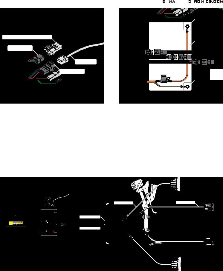
2. Connecting To CAN bus & Battery |
DENALIELECTRONICS.COM |
|
Positive Terminal |
Cap or |
|
ABS Dongle/ Offroad Fuel Dongle** |
Battery |
|
|
CANsmart CANbus |
|
Connector Female |
|
Vehicle CANbus |
|
Connector |
|
CANsmart CANbus |
|
Connector Male |
|
|
Negative Terminal |
2.1 - Connecting To The CAN bus
Step One: Locate your bikes Diagnostic Port. The port is a gray 6-pin female MT Series connector. In general the connector is located underneath the riders seat. For the exact location, check your bikes owners manual.
Step Two: Remove the cap**.
Step Three: Next connect the male CAN bus connector on the CANsmart™ Controller to the Diagnostic Port.
Step Four: Install the cap** to the female CAN bus connector on the CANsmart™.
**Note: If your KTM has a ABS Dongle or Offroad Fuel Dongle installed, simply connect it to the female CANbus connector.
3. Connecting Accessories
2.2 - Connecting To The Battery
Step One: Remove the fuse from the fuse holder.
Step Two: Gain access to the vehicle’s battery and disconnect the negative (-) and positive (+) terminals.
Step Three: Connect the CANsmart™ wiring harness to the battery via the ring terminals. Be sure the orange wire lead with the fuse holder goes to the positive (+) terminal of the battery.
Step Four: Re-install the fuse into the fuse holder.
Note: Place the fuse holder in an easily accessible location for convenient service in the event of a blown fuse.
Light Set One |
Light Set Two |
Light Extension
Light Extension
3.1 - Light Set One & Two - (Red & White Circuits)
In the default configuration, the circuit for Light Set One is the longest red lead, the shortest white lead is for Light Set Two. Both circuits are designed to handle up to 10 amps each.
Step One: Plug the male 3-pin connector of the Light Extension-Splitter into one of the CANsmart™ Controller’s light circuits.
Step Two: Begin routing the harness toward the front of the bike. Secure the harness to the vehicle’s frame along the way with the included zip ties. Be sure to avoid any moving components such as radiator fan blades or suspension.
Step Three: Plug the DENALI Light Pods into the female 3-pin connectors of the Extension-Splitter. Repeat steps One through Three using a second Light Extension-Splitter for the second set of lights.
Two-Wire Dimming: Turn off “Three-Wire Dimming Mode” for correct dimming operation of auxiliary LED lights that have only two wires. If enabled the 3rd yellow wire will be deactivated and PWM data will instead be transmitted through the red wire.
Wire two wire lights using the red wire for positive (+) and the black wire for negative (-).
 Loading...