

Page 1

DEMA Pro-Fill I Sink Dispenser
MODELS PF651GAP, PF651AG, PF651GAP-1M, & PF651AG-1M
Overview
The PRO-FILL I Sink Dispenser mixes water with a cleaning chemical and dispenses the solution
into holding containers such as sinks. The dispenser is equipped with an ASSE 1055B Approved
backflow device.
Each dispenser can be set up to meet specific application needs with the ability to offer:
High flow dispensing of a single product
Chemical dilution ratios up to 7:1
Supplied metering tips allow for preset dilution ratios
4 gallon per minute dispensing
Warnings
All installations must conform to local plumbing codes and use approved backflow
prevention devices. A pressure indicating tee is to be installed with existing faucets
according to local plumbing codes in the state of Wisconsin and any other state that
requires the use of a pressure indicting tee.
ALWAYS WEAR PROTECTIVE CLOTHING AND EYEWEAR WHEN
WORKING WITH CHEMICAL PRODUCTS.
I-963 Page 1 of 6
Rev. E-37870 5/17/12
Page 2
Part
Number
Description
PF651GAP
PF651AG
PF651GAP-2M
PF651AG-2M
L806
CHEMICAL LABELS
1 1 1
1
100-15K
METERING TIP KIT
1 1 1
1
61-107-2
SMALL CERAMIC
WEIGHT
2 2 2
2 100-16E-1
TUBING & FOOT
VALVE 1/4" X 8'
2 2 2
2
61-21
OUTLET TUBE
1/2" X 6'
1 1 1
1
63-83
OUTLET TUBE
9/16" X 6'
1 1 1
1
66-53-4
MOUNTING SCREW
1 1 1
1
66-52
WALL ANCHOR
4 4 4
4
Water Supply Requirements
Minimum
Maximum
Water Pressure
20 psi (1.38 bar)
125 psi (8.62 bar)
Water Temperature
-
*150ºF (65.5ºC)
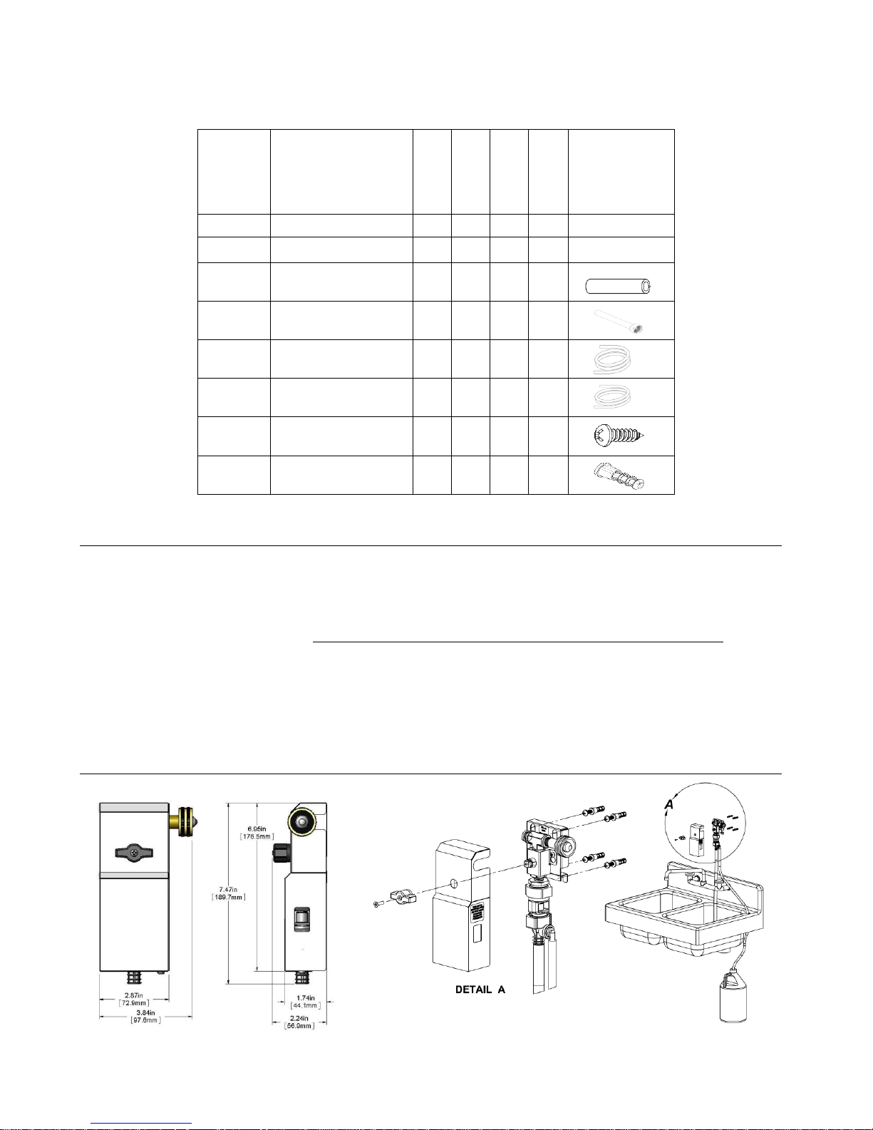
Packing List
Operational Requirements
*Caution: 150ºF (65.5ºC) is “hot” to the touch and must be handled with care.
Overall Size Typical Install
I-963 Page 2 of 6
Rev. E-37870 5/17/12
Page 3

Metering
Tip
Color
163 BAG (4 GPM Flow Rate Air Gap Proportioner)
Injection Rates For Viscosities Shown
(4 GPM Flow Rate Action Gap Proportioner)
Injection Rates For Viscosities Shown
1 cps
75 cps
200 cps
1 cps
75 cps
200 cps
Oz/Gal
Ratio
Oz/Gal
Ratio
Oz/Gal
Ratio
Oz/Gal
Ratio
Oz/Gal
Ratio
Oz/Gal
Ratio
Tan
0.30
427-1
0.20
640-1
0.15
853-1
0.33
387-1
0.26
500-1
0.12
1090-1
Orange
0.40
320-1
0.30
427-1
0.25
512-1
0.42
307-1
0.32
430-1
0.17
735-1
Turquoise
0.60
213-1
0.40
320-1
0.30
427-1
0.51
251-1
0.34
382-1
0.19
676-1
Pink
0.80
160-1
0.50
256-1
0.40
320-1
0.78
165-1
0.56
230-1
0.3
422-1
Light Blue*
1.00
128-1
0.70
183-1
0.45
284-1
0.87
147-1
0.67
192-1
0.33
391-1
Brown
1.20
107-1
0.80
160-1
0.50
256-1
0.99
129-1
0.74
174-1
0.37
345-1
Red
1.50
85-1
0.90
142-1
0.60
213-1
1.37
93-1
0.91
141-1
0.44
289-1
White
1.85
69-1
1.10
116-1
0.70
183-1
1.52
84-1
1.04
123-1
0.48
264-1
Green
2.00
64-1
1.25
102-1
0.80
160-1
1.72
74-1
1.22
105-1
0.52
244-1
Blue
2.50
51-1
1.50
85-1
0.82
156-1
2.13
60-1
1.27
101-1
0.54
239-1
Yellow
4.00
32-1
1.85
69-1
0.90
142-1
3.05
42-1
1.71
75-1
0.56
229-1
Black
5.50
23-1
2.00
64-1
0.94
136-1
4.50
28-1
1.96
65-1
0.57
224-1
Purple
8.80
15-1
2.40
53-1
0.96
133-1
7.75
17-1
2.4
53-1
0.59
217-1
Gray
11.65
11-1
2.50
51-1
1.00
128-1
9.86
13-1
2.54
50-1
0.63
204-1
No Tip
16.20
8-1
3.00
43-1
1.20
107-1
19.63
7-1
3.16
40-1
0.67
190-1
Installation
Mounting Dispenser Assembly
1. Remove the ball valve screw and knob then slide the cover off of the valve
assembly.
2. Position the dispenser on the wall and mark the four mounting screw
locations.
3. Install the supplied anchors in the wall and install the screws half way into
the anchors.
4. Slide the dispenser over the screw heads and tighten down the screws.
5. Install the desired metering tip in the elbow as shown.
6. Cut the chemical supply tube to length by removing excess tubing. Install
the supplied ceramic weight onto the tube then install the tube onto the
elbow barb. Place the tube end with the ceramic weight and foot valve into
the proper chemical container. Note: Chemical container can be no greater
than 6’ (1.83 meters) below the dispenser.
7. Cut outlet tubing to desired length and install to proportioner barb. Properly
place tubing in sink where chemical is desired.
8. Replace the cover, ball valve knob, and tighten the screw.
Water Supply
(Inlet pressure must be between 20 psi (1.38 bar) and 125 psi (8.62 bar)).
1. Attach a garden hose to the water inlet on the unit.
Table 1: “Air Gap” & “Action Gap” Induction Flow Rates w/Standard 1/4" Barb and Tubing
*Metering tip color was formerly clear.
Notes: All induction flow rates are based on a water pressure of 40 psi.
(1 cps (centipoises)-viscosity of water, 75 cps-viscosity of light weight detergents, 200 cps-viscosity of most dishwasher detergents)
Leaner dilutions can be achieved by ordering DEMA ultra lean metering tip kit 100-15KU.
Ratios as low as 100 parts-per-million can be achieved with the use of a DEMA capillary metering tip. Contact DEMA customer service
for more information.
If you are having difficulty achieving the ratio you require, call DEMA and ask for the technical service department.
I-963 Page 3 of 6
Rev. E-37870 5/17/12
Page 4
Symptom
Probable Cause
Remedy
Proportioner fails to draw
chemical properly.
1. Insufficient water supply pressure.
2. Foot valve has dirt/chemical
build-up.
3. Proportioner metering tip clogged
with dried chemical.
4. Mineral deposits are located on
Air Gap nozzle.
5. Valve not rotated in fully open
position.
1. 20 PSI is the minimum allowable pressure. Seek
Plumber if necessary to increase water pressure.
2. Soak in hot water to clean.
3. Soak in hot water to clean interior passages.
4. Soak nozzle and inlet screen in hot water or
product such as CLR to clean mineral deposits.
5. Always turn knob in fully opened positions.
“Air Gap” Proportioner is
dripping or spraying a mist
(fan pattern) of water.
1. Mineral deposits are located on
Air Gap nozzle.
1. Soak nozzle and inlet screen in hot water or
product such as CLR to clean mineral deposits.
Water valve is not shutting
off completely.
1. Ball valve not closed.
2. Ball valve has internal leakage.
1. Always turn knob clockwise to fully closed
position.
2. Replace ball valve
Threaded connections are
leaking water.
1. The connection between the sink
dispenser and water supply line is
too loose or rubber washer is
missing.
2. Backflow prevention devices
and/or proportioners are too loose.
1. Shut water supply off first. Carefully tighten the
female hose coupling on the sink dispenser to
the inlet water supply line. Do not overtighten.
2. Tighten loose connection(s) with tools if
necessary. Do not overtighten if using tools.
Proportioner continues to
draw chemical after water
valve is closed.
1. Concentrated chemical is
positioned higher than the
proportioner.
1. Move the concentrated chemical so it is lower
than the proportioner.
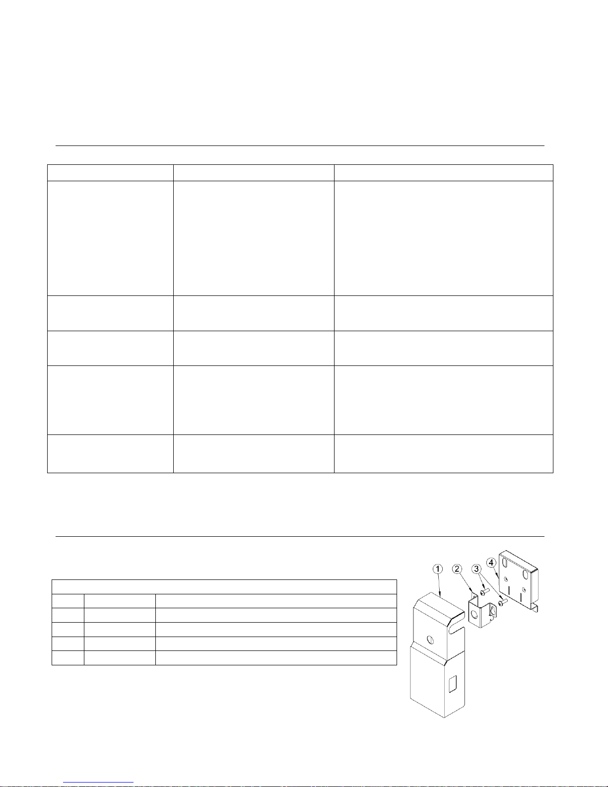
COVER, MOUNTING BRACKETS, AND HARDWARE
NO.
PART NO.
DESCRIPTION
1
65-38-1
Cover, Dual Valve (Stainless Steel)
2
65-37-1
Bracket, Valve Retaining (Stainless Steel)
3
60-67-1
#8 X ½” Lg. Screw (Type B)
4
65-36-1
Bracket, Wall Mounting (Stainless Steel)
Operation
The operation of this unit is simple. Once all the correct tubing is in place, simply rotate the correct
ball valve knob to the “on” position and let the chemical/water solution fill the sink to the desired
level. Now rotate the ball valve fully into the “off” position.
Troubleshooting
Parts List (See pages 4-5)
I-963 Page 4 of 6
Rev. E-37870 5/17/12
Page 5
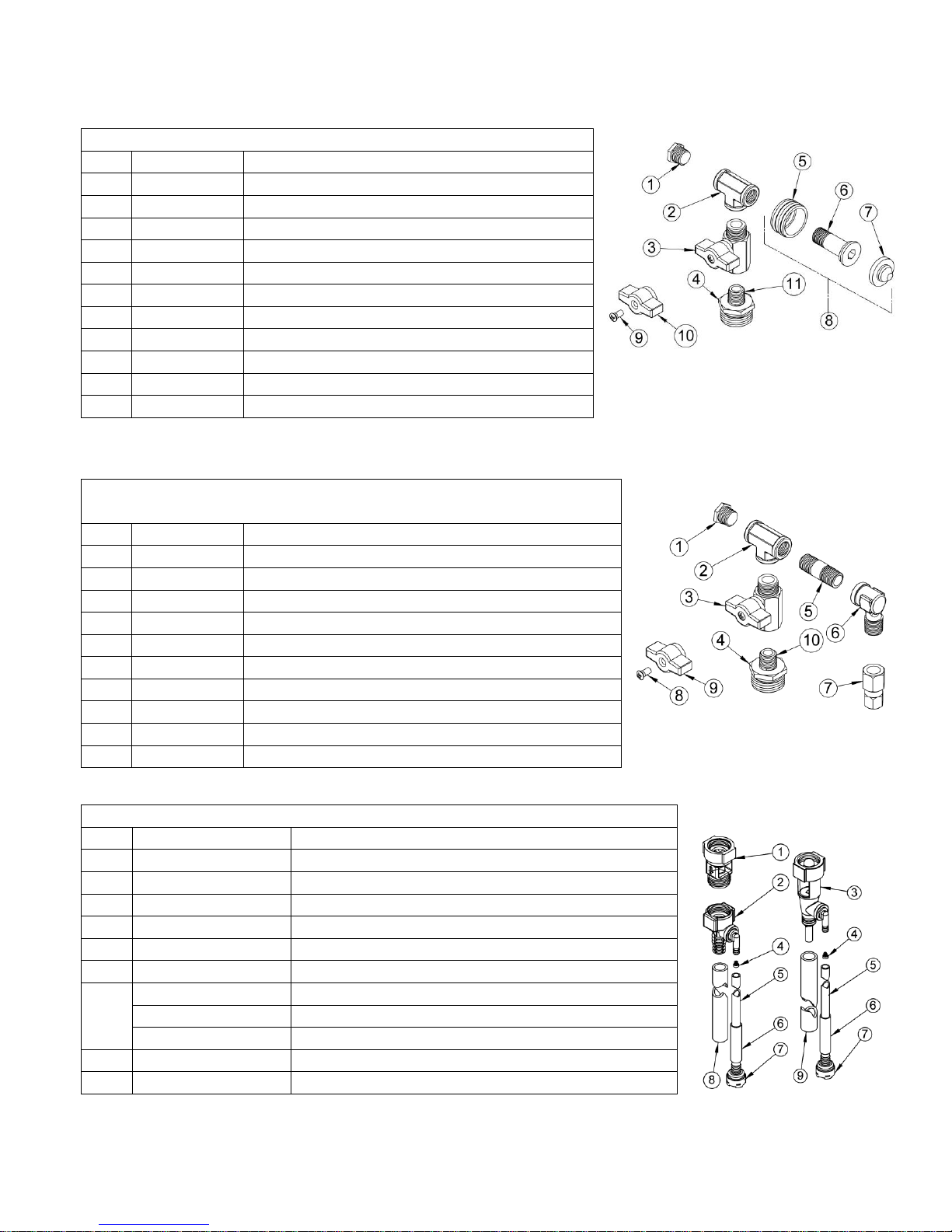
PF651GAP & PF651AG DUAL BALL VALVE ASSEMBLY
NO.
PART NO.
DESCRIPTION
1
65-6
¼” NPT Plug
2
65-30-1
¼” NPT Tee
3
65-7
¼” NPT Ball Valve with Knob
4
65-31-3U
Adapter, Garden Hose X ¼” NPT (brass)
5
65-10
Garden Hose Coupling
6
65-17-2
Hose Adapter Stem
7
100-38
Strainer Washer
8
65-11
Swivel Adapter Kit
9
81-19-20
Knob Screw
10
65-2K
Knob
11
25-137-6U
¼” NPT Nipple
PF651GAP-2M & PF651AG-2M DUAL BALL VALVE
ASSEMBLY
NO.
PART NO.
DESCRIPTION
1
65-6
¼” NPT Plug
2
65-30-1
¼” NPT Tee
3
65-7
¼” NPT Ball Valve with Knob
4
65-31-3U
Adapter, Garden Hose X ¼” NPT (brass)
5
25-137-12U
¼” NPT Nipple
6
61-121
¼” Street Elbow
7
25-51-12
¼” NPT X 3/8” O.D. Tube Compression Fitting
8
81-19-20
Knob Screw
9
65-2K
Knob
10
25-137-6U
¼” NPT Nipple
BACK FLOW/PROPORTIONING DEVICES, TIPS, & TUBING
NO.
PART NO.
DESCRIPTION
1
16-30
ACTION GAP Assembly
2
61-22-3
Proportioner Assembly (4 GPM) w/Elbow
3
61-22-3BAG-EL2
AIR GAP Proportioner Ass’y (4 GPM) w/Elbow
4
100-15K
Metering Tip Kit (14 Sizes)
5
100-12
¼” I.D. X 8’ Lg. Vinyl Tubing
6
61-107-2
Ceramic Weight (3/8” I.D.)
7
100-16E
Foot Valve Assembly (EPDM) – Std. Equipment
100-16S
Foot Valve Assembly (Silicone) - Available
100-16V
Foot Valve Assembly (Viton) - Available
8
61-21
½” I.D. X 6’ Lg. Vinyl Tubing
9
63-83
9/16” I.D. X 6’ Lg. Vinyl Tubing
I-963 Page 5 of 6
Rev. E-37870 5/17/12
Page 6

Warranty
Merchandise Returns
No Merchandise will be Returned for Credit Without DEMA’S Written Permission. Returned Merchandise
Authorization Number is Required in Advance of Return.
Product Warranty
DEMA products are warranted against defective material and workmanship under normal use and service for one
year from the date of manufacture. This limited warranty does not apply to any products that have a normal life
shorter than one year or failure and damage caused by chemicals, corrosion, physical abuse, or misapplication.
Rubber and synthetic rubber parts such as “O”-rings, diaphragms, PVC tubing, and gaskets are considered
expendable and are not covered under warranty. This warranty is extended only to the original buyer of DEMA
products. If products are altered or repaired without prior approval of DEMA, this warranty is void.
Defective units or parts should be returned to the factory with transportation prepaid. If inspection shows them
to be defective, they will be repaired or replaced without charge, F.O.B. factory. DEMA assumes no liability for
damages. Return merchandise authorization number must be granted in advance of returned units for repair or
replacement (See “Merchandise Returns” above).
I-963 Page 6 of 6
Rev. E-37870 5/17/12
 Loading...