Dema DM-812 Installation Manual

DEMAMasterTM DM-812 Series Installation Manual
I-808 |
Pg 1 of 8 |
Rev B |
|

DEMAMasterTM DM-812 Series Installation Manual
System Overview
The DEMAMaster series is designed for long reliable use with simplicity in mind for both the installer and user. The DEMAMaster dispenses using the reliable DEMA peristaltic pump or DEMA solenoid valve for dry detergent applications. The electical controls are installed in a heavy plastic housing with a sealed cover that uses a Lexanb label with visible function indicators.
Pumps are available with three different motor/gear box speeds, 15, 60, and 105 RPM.
There are micro controllers housed in the unit that control the operation of the pump or valve. By use of the various DEMA control baords, chemical products can be dispensed in a manner that will allow proper usage of the chemical product.
Please read all instructions before proceeding with the DEMAMaster installation.
Preperation for Installation
First step in the installation is to know what type of DEMAMaster is to be installed. The following table will help identify the unit to be installed. This instruction sheet is only for those model numbers listed.
Table 1
DEMAMaster General Specifications
Model Number |
Hook Up Power |
Transformer |
Pump or Valve |
Control Board |
||||
Qty |
Detergent |
Rinse |
Detergent |
Rinse |
||||
|
|
|||||||
DM-812-LL-2T |
|
|
Pump (C2) |
|
81-117-1 |
|
|
|
DM-812-DL-2T |
|
2 |
Valve |
|
|
|
||
|
|
|
|
|
||||
DM-812-PLL-2T |
|
Pump (C2) |
|
80-77-1 |
|
|
||
|
|
|
|
|
||||
DM-812-PDL-2T |
120/208/240VAC |
|
Valve |
|
|
|
||
|
|
|
|
|
||||
DM-812-LL-1T |
|
Pump (C2) |
Pump |
81-117-1 |
80-69-5 |
|
||
|
|
|
||||||
DM-812-DL-1T |
|
1 |
Valve |
(C2) |
|
|||
|
|
|
|
|||||
DM-812-PLL-1T |
|
Pump (C2) |
|
80-77-1 |
|
|
||
|
|
|
|
|
||||
DM-812-PDL-1T |
|
|
Valve |
|
|
|
||
|
|
|
|
|
|
|||
DM-812-LL-0T |
24VAC |
None |
Pump (C2) |
|
81-117-1 |
|
|
|
DM-812-DL-0T |
Valve |
|
|
|
||||
|
|
|
|
|
|
|||
I-808 |
Pg 2 of 8 |
Rev B |
|

DEMAMasterTM DM-812 Series Installation Manual
Electrical Installation
All installations must be in accordance with city, county, state or provincial electrical codes and be performed by a certified electrician. It is recommended to use a local licensed electrical contractor for the installation of this product.
1.All electrical power must be turned off to the dish or cleaning machine and any other circuits that is to be used for this installation. Lockout and tag procedures must be observed when installing this device.
Never open the DEMAMaster while power is applied. Signals may be active from cleaning machine, even with the DEMAMaster power turned off. Use appropriately rated insulated wiring, electrical fixtures and other materials that meet all applicable electrical and building codes.
2.Wire the DEMAMaster to the dish or cleaning machine. The wiring configuration will depend on the transformer configuration of the DEMAMaster. It will have either 1, 2 or no transformers. The
transformers are setup to utilize 120/208/240VAC 60Hz power.
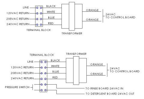
2 Transformers (see figure 1): Each transformer will be wired to a control board individually. The power should be wired to the appropriate transformer based on the control board.
∙Detergent in most cases will be supplied during the wash cycle. The power can be picked up parallel with the low voltage side of the wash pump.
∙Rinse board will be powered during the rinse cycle. The power can be picked up parallel with the rinse solenoid.
∙There may be alternatives than those listed above. Additionally, the dish or cleaning machine may be equipped with terminals specifically for wiring an automatic chemical dispenser.
1 Transformer (see figure 2): Both boards are powered off the same transformer.
∙Power in comes from main power of machine. Detergent board always has power and operates
accordingly. Rinse is cycled on by use of the pressure switch mounted to the rinse manifold. This type of hook up is normally on a conveyor type machine not a door machine.
No Transformers: Both boards must be powered directly at the 24VAC in terminals on each board.
∙This is used on special applications where 24VAC 60Hz is available to operate the control boards properly. See the control board instruction sheet for location of 24VAC terminals.
Figure 1
Figure 2
I-808 |
Pg 3 of 8 |
Rev B |
|
 Loading...