

DEMA Chemaster DM-813-PLLL-1T, Chemaster DM-813-PDLL-2T, Chemaster DM-813-PLLL-2T, Chemaster DM-813-PDLL-1T Installation Instructions Manual

DEMA 813 PROBELESS DEMAMaster
INSTALLATION INSTRUCTIONS
TM
I-729 Pg 1 of 15
Rev D 11/01
Models:
DM-813-PLLL-1T
DM-813-PDLL-1T
DM-813-PLLL-2T
DM-813-PDLL-2T

System Overview
The DEMA DEMAMaster probeless series is designed for long reliable use with simplicity in mind for both
the installer and user. The system is based on the reliable DEMA peristaltic pump. The pumps are installed
in a heavy plastic housing with a sealed cover that uses a Lexan label with visible function indicators.
Pumps are available with three different motor/gear box speeds, 15, 60, and 105 RPM.
There are micro controllers housed in the unit that control the operation of the pumps. The detergent pump
is controlled by a set of DIP switches that can be arranged to supply a selected amount of detergent based on
door counts or time depending on the application. The rinse aid is set by a potentiometer that controls the
speed of pump and can be delayed up to 12 seconds. In addition, the probeless detergent board has the
ability to keep track of time and deliver a new initial charge when in the door mode.
The DEMAMaster is supplied with a transformer mounted in housing that allows primary voltage hook up of
120, 208 or 240 at 50/60Hz.
Please read all instructions before proceeding with the DEMAMaster installation.
Dishroom Room Survey
A complete survey of the dish machine sight should be completed before the DEMAMaster installation.
1. Locate the power connection points on the dish machine. This power must be 120, 208 or 240 volts
50/60Hz.
Note: When installing a DEMAMaster probeless on a door operated dish machine, keep in
mind that the detergent control will need to recognize door openings based on power
“on” and “off” to the DEMAMaster. In addition, all installations will require that the
rinse control recognize the dish machine rinse cycle.
2. Select location to mount the DEMAMaster on a wall that will allow access to the chemical product
containers and the chemical product feeds points on the dish machine. The DEMAMaster should be
kept away from moisture releasing machinery and from water being splashed directly on the unit.
3. Mount the DEMAMaster on a wall by use of the supplied hanger. Use appropriate wall anchors
when mounting on dry wall.
I-729 Pg 2 of 15
Rev D 11/01

Electrical Installation
1. BEFORE GOING ANY FURTHER, ALL ELECTRICAL POWER MUST BE TURNED OFF TO
2. Connect the power to the DEMAMaster. The DEMAMaster will accept 120VAC, 208VAC or
This product is designed only to be used as described in this instruction sheet. Adhere to all warnings an d
cautions identified in this document.
WARNING: Electrical and grounding installation of DEMA products must comply with
electrical codes and regulations established by national, city, county, parish, provincial or
other agencies. It is possible that electrical codes and regulations require that a certified
electrical contractor or engineer perform the electrical installation.
For questions, contact a certified electrician.
DISCONNECT ALL ELECTRICAL POWER TO THE DISPENSER AND THE APPLIED
MACHINE WHEN SERVICING- FOLLOW LOCKOUT / TAGOUT PROCEDURES.
WARNING: Installations must conform to all local and national plumbing codes and use
approved backflow prevention and pressure relief devices where required.
ALWAYS DISCONNECT DISPENSER FROM WATER SOURCE WHEN DISPENSER
IS NOT IN USE.
Always read SDS for all chemicals used and follow personal protective guidelines.
THE DISH MACHINE AND ANY OTHER CIRCUIT THAT IS TO BE USED FOR THIS
INSTALLATION. LOCKOUT AND TAG PROCEDURES SHOULD BE OBSERVED WHEN
INSTALLING THIS DEVICE. NEVER OPEN THE DEMAMASTER UNLESS POWER HAS
BEEN TURNED OFF. SIGNALS MAY BE PRESENT FROM DISH MACHINE, EVEN WITH
THE POWER TURNED OFF. ONLY USE ELECTRICAL CODE APPROVED INSULATED
WIRING AND ELECTRICAL FIXTURES WITH THIS INSTALLATION.
Note: The DEMAMaster is equipped with 1 or 2 transformers depending on the model. If
there are 2 transformers, the detergent control will be powered by one while the rinse
aid control, will be powered by the other.
If the DEMAMaster is equipped with 1 transformer, both the detergent and rinse
control, will be powered by the same transformer. In this case it will be necessary to
wire the unit so that the rinse aid control will only run during the rinse cycle. This can
be done via a pressure switch, which should be wired to the DEMAMaster terminal
block connections labeled “pressure switch”.
240VAC 50/60Hz. The detergent control is normally wired to something that is common to the
pump operation, thus signaling a wash cycle. The rinse control is normally wired to something that is
common to the rinse solenoid valve, thus signaling a rinse cycle. Some dish machines may have a
terminal block setup for power for both detergent and rinse, see schematic or owners manual of the
dish machine to determine if this option is available.
I-729 Pg 3 of 15
Rev D 11/01

3. Locate the power terminal block inside the DEMAMaster enclosure. There will be 2 when there are
2 transformers. Connect “hot” or “live” wire to the terminal labeled “line”. Connect the “return
line” to the appropriate terminal block position based on supply voltage. The “earth ground” wire
must be connected to the terminal block by use of the grounding clip (supplied in installation kit).
The power line should be secured by use of a proper electrical fitting through access hole in
DEMAMaster enclosure. The power line must also be secured properly between the dish machine or
power source and DEMAMaster.
Note: When wiring is completed the DEMAMaster should feed detergent based on door counts or
time depending on type of machine (door or conveyor). The rinse aid should feed only during the
rinse cycle. It may be necessary to use a pressure switch to signal the rinse aid feed. Evaluate the
application for requirements to assure proper operation.
I-729 Pg 4 of 15
Rev D 11/01

80-77-1
CONTROL BOARD
PROBLESS DETERGENT
X20753-7 (81-32-7) VALVE
(SEE DRAWING FOR PART NO.)
24VDC OUT
BLACK
RED
X20753-2 (81-32-2) MOTOR
MOTOR OR
VALVE
SOLENOID
RINSE CONTROL BOARD
80-69-6
24VDC RINSE OUT
24VDC SANI OUT
24VAC OUT
24VAC IN
X20753-2
(81-32-2)
(SEE DRAWING FOR PART NO.)
X20753-1 (81-32-1) MOTOR
X20753-6 (81-32-6) VALVE
20758-1 (81-35) FUSE HOLDER
MOTOR
25457-16 (81-34-16) FUSE
ORANGE
ORANGE
TRANSFORMER
40 VA
80-70
(81-36-2)
DETERGENT
20759-2
X20753-1
(81-32-1)
SANI
24VAC IN
UNUSED
+
++
BLACK
RED
X20753-1
(81-32-1)
BLACK
ORANGE
X20753-2
(81-36-2)
20759-2
(81-32-2)
FOR PART NO.)
ORANGE
(SEE DRAWING
TRANSFORMER
80-70
25457-16 (81-34-16) FUSE
20758-1 (81-35) FUSE HOLDER
RED
MOTOR
RINSE
40 VA
FUSE
1A. 250V
RED
BLUE
RED
(SEE DRAWING FOR PART NO.)
TERMINAL BLOCK &
BRACKET ASSY.
240VAC RETURN
208VAC RETURN
120VAC RETURN
BLACK
WHITE
(SEE DRAWING FOR PART NO.)
TERMINAL BLOCK &
BRACKET ASSY.
LINE
240VAC RETURN
BLUE
208VAC RETURN
FUSE
1A. 250V
BLACK
WHITE
LINE
120VAC RETURN
I-729 Pg 5 of 15
Rev D 11/01

PROBLESS DETERGENT
CONTROL BOARD
80-77-1
80-69-6
RINSE CONTROL BOARD
24VDC SANI OUT
24VDC RINSE OUT
X20753-2 (81-32-2) MOTOR
X20753-7 (81-32-7) VALVE
24VDC OUT
+
RED
X20753-1 (81-32-1) MOTOR
X20753-6 (81-32-6) VALVE
BLACK
(81-94-2)
24VAC IN
24VAC OUT
20774-2
(81-94-1)
24VAC IN
+
RED
(81-32-2)
X20753-2
(81-32-1)
X20753-1
+
BLACK
RED
BLACK
ORANGE
ORANGE
UNUSED
20774-1
(81-94-1)
ORANGE
(SEE DRAWING FOR PART NO.)
MOTOR
SANI
TRANSFORMER
40 VA
80-70
(81-32-1)
X20753-1
20774-1
(81-32-2)
X20753-2
(81-36-2)
20759-2
25457-16 (81-34-16) FUSE
20758-1 (81-35) FUSE HOLDER
(SEE DRAWING FOR PART NO.)
MOTOR OR
VALVE
SOLENOID
DETERGENT
ORANGE
2
SWITCH
I-729 Pg 6 of 15
Rev D 11/01
ORANGE
1
PRESSURE
RED
240VAC RETURN
BLUE
208VAC RETURN
120VAC RETURN
WHITE
FUSE
1A. 250V
BLACK
(SEE DRAWING FOR PART NO.)
LINE
BRACKET ASSY.
TERMINAL BLOCK &
(SEE DRAWING FOR PART NO.)
MOTOR
RINSE

Tubing Connections
Included in the installation kit is a roll of low-density polyethylene (LDPE) tubing that can be used to
connect from the chemical container, to the pump, and from the pump to the injection fittings on the
machine.
Measure the length of the tubing needed on the suction side from the chemical container to the pump and cut
the tubing to proper length. Install the tubing into the pickup tubes (Grey PVC) through the compression nut,
and tighten the nut. Route the tubing to the suction side of the pump. An arrow on the faceplate indicates
the flow direction. Push the tubing into the pump squeeze tube approximately1/2-3/4”(15-20mm). Secure
the tubing with a tie wrap around the squeeze tube. Use the same procedure on the outlet of the squeeze
tubing and route the LDPE tubing to the injection point of the machine. Cut off all excess tubing and keep
tubing away from hot surfaces and sharp edges to prevent damage or leakage.
See Detergent and Rinse Tubing Connections below for specific information concerning discharge tube
connection.
Detergent Tubing Connections
Included with the kit is a bulkhead fitting that will accept the discharge of the detergent at the machine.
There are two fittings depending on the model. If the DEMAMaster has a detergent pump, then the fitting
will have a ¼” compression fitting that will accept the ¼” LDPE pump discharge tubing. It the unit has a
solenoid valve then the fitting will have a barb fitting designed for a 5/8” I.D. tube. A 7/8” diameter hole
will need to be cut above the waterline in the side of the dish machine wash tank to accommodate the
bulkhead fitting. The bulkhead fitting should not be located above the concentration probe.
When using the detergent pump simply run the tubing from the outlet of the pump to the ¼” compression
fitting on the bulkhead fitting.
When using the solenoid valve run the ¼” LDPE tubing from the ¼” compression fitting on the outlet of the
valve to the siphon breaker for the solid bowl or powder feeder.
Rinse Tubing Connections
Note: A check valve is included in the installation kit. The procedure below describes the installation of this
check valve. Other hardware may be needed to complete the installation properly.
Install ¼” compression by 1/8” NPT rinse injection check valve into the rinse input water between the
vacuum breaker and the final rinse arm. Drill an 11/32” hole and tap to 1/8” NPT. When installing to
copper pipe or tubing use saddle clamps.
Connect the ¼” OD poly tubing between the ¼” rinse check valve and the discharge side of the peristaltic
rinse squeeze tubing. Use a plastic tie to hold the ¼” polypropylene tubing into the peristaltic squeeze tube.
Detergent and Rinse Calibration
Detergent
Prior to calibration the system must be primed. The system is primed when the chemical is dispensing from
the injection point into the dish machine tank. This can only be done while power is being supplied to the
probeless detergent board. By pressing the button on the front cover labeled “detergent prime” the pump
will run. Simply press and hold until the pump and tubing has been primed.
Note: If Detergent Prime button is held less than 5 seconds, the pump will run for the amount time
that has been set for initial charge or until button is pushed again.
I-729 Pg 7 of 15
Rev D 11/01

The detergent set up involves the use of the DIP switches on the pro-bless detergent control board. There are
a bank of 6 and a bank of 8 switches located directly on the control board. The detergent concentration
should be setup so that the desired level of concentration is maintained while the dish machine is being used.
The concentration can be tested by use of a titration test kit (DEMA P/N 81-53), not included.
1. Door or Conveyor mode: 6 DIP Switch Bank, Switch 1
12345 6 421 356
2. Initial Charge Time: Sets the amount of Initial Charge based on time. See table below for the P switch
configuration.
0
5 SEC
10 SEC
15 SEC
20 SEC
25 SEC
30 SEC
35 SEC
213
213
213
213
321
213
213
213
4
4
4
4
4
4
4
4
56
56
56
56
5
6
567
567
56
7
8
7
8
7
8
7
8
7
8
8
8
7
8
1 MIN
1 MIN 5 SEC
1 MIN 10 SEC
1 MIN 15 SEC
1 MIN 20 SEC
1 MIN 25 SEC
1 MIN 30 SEC
1 MIN 35 SEC
1234576
1234
2143
56
1234 765
54321
1234 765
1234
1234
1 MIN 50 SEC
8
8
8
8
8
8
8
8
1 MIN 55 SEC
2 MIN
2 MIN 5 SEC
2 MIN 10 SEC
2 MIN 15 SEC
2 MIN 20 SEC
2 MIN 25 SEC
65
7
7
6
7
756
65
7
1234
1234
1234
1234
1234
21
1234
4321
586
56
56
56
576
567
43
5687
56
7
7
8
7
8
7
8
8
8
7
8
40 SEC
45 SEC
50 SEC
55 SEC
321
123
213
213
I-729 Pg 8 of 15
Rev D 11/01
4
4
4
4
5
6
576
56
5687
7
8
8
7
8
1 MIN 40 SEC
1 MIN 45 SEC
1234576
5123476
8
8
2 MIN 30 SEC
2 MIN 35 SEC
1234
576
54321
8
6
7
8

3A. Dead Cycle Count – Door Mode Only
Sets the amount of wash cycles (door operations) that will take place before a recharge will occur.
See table below for DIP switch configuration. Example: If the Dead Cycle Count is set to 3, there
will be three wash cycles where no detergent will be added. On the 4
th
cycle a recharge will occur.
0 CYCLES
1 CYCLE
2 CYCLES
3 CYCLES
614325
652341
652341
6
14325
3B. Dwell Time Setting – Conveyor Mode Only
Sets the amount of time between a charge and a recharge and recharges. See table below for DIP
switch configuration. Example: Dwell Time is set for 1 min 30 sec. After the probeless control
supplies an initial charge or a recharge, 1 minute and 30 seconds must expire before the next
recharge will occur.
0
15 SEC
30 SEC
2143
123 4
65
56
4123
65
3 MIN
3 MIN 15 SEC
3 MIN 30 SEC
4 CYCLES
5 CYCLES
6 CYCLES
7 CYCLES
123
132
132
652341
1
6
4325
6
1423 5
61423 5
645
654
654
5 MIN 30 SEC
5 MIN 45 SEC
6 MIN
321456
3
12
3
21
456
564
45 SEC
1 MIN
1 MIN 15 SEC
1 MIN 30 SEC
1 MIN 45 SEC
2 MIN
2 MIN 15 SEC
2 MIN 30 SEC
2 MIN 45 SEC
312 4
123 4
2143
123 4
1324
123 4
2143
123 4
312 4
56
56
56
56
56
56
3 MIN 45 SEC
4 MIN
65
4 MIN 15 SEC
4 MIN 30 SEC
65
4 MIN 45 SEC
5 MIN
65
5 MIN 15 SEC
123
3
12
3
21
312
3
31221546
645
546
456
564
654231
456
6 MIN 15 SEC
6 MIN 30 SEC
6 MIN 45 SEC
7 MIN
7 MIN 15 SEC
7 MIN 30 SEC
7 MIN 45 SEC
12
12
312
546
3
21
456
321
546
3
21
456
546
3
3
546
321
456
I-729 Pg 9 of 15
Rev D 11/01
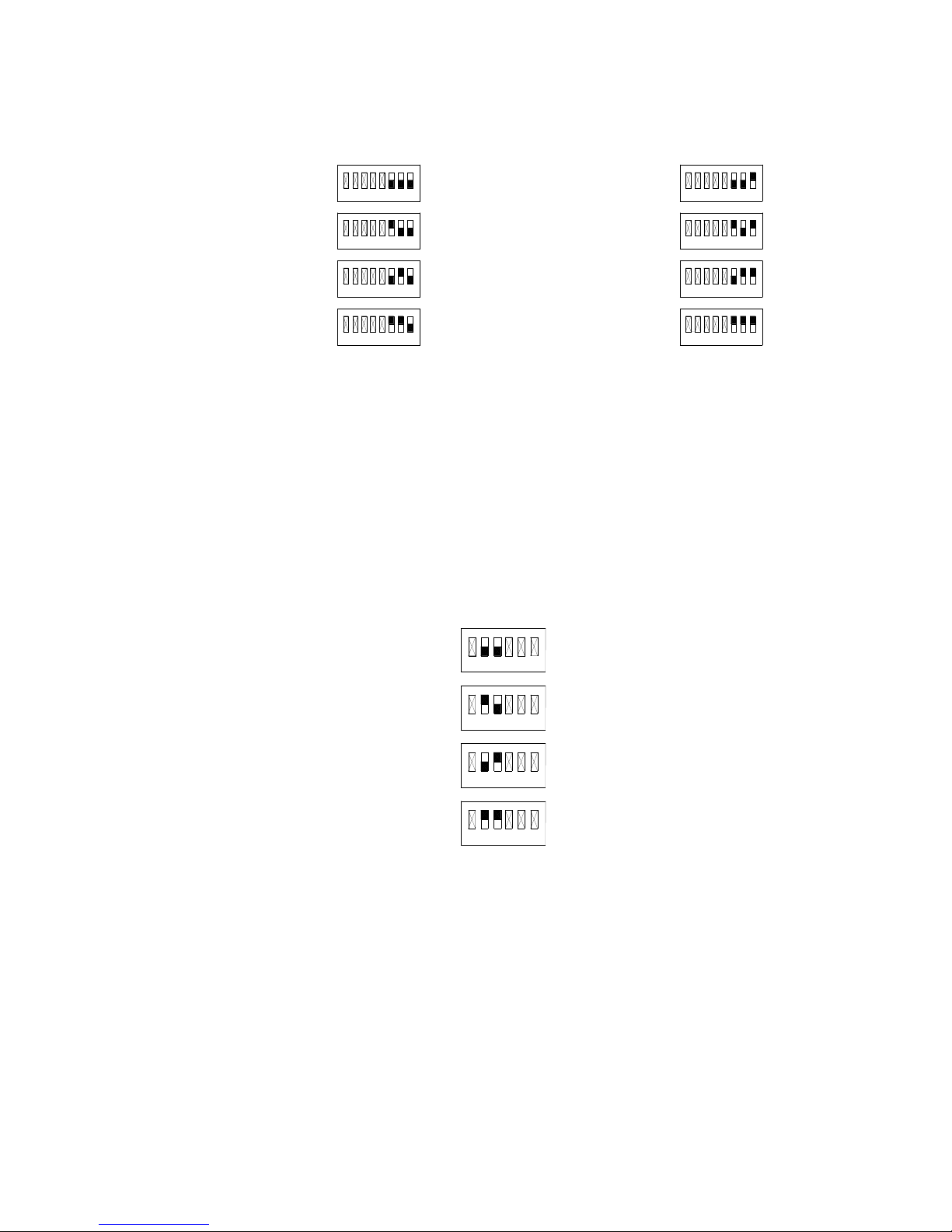
4. Recharge Time: Sets the amount of recharge based on time. See table below for DIP switch
configuration.
1 SEC
2 SEC
3 SEC
4 SEC
5. Initial Charge Clock
This feature is adjustable as shown below while in door mode only. When the unit is in the
conveyor mode the initial charge clock defaults to 1 hour.
This feature is used to provide an initial charge after a set amount of time expired without
using the DEMAMaster. See the table below for the DIP switch configuration. Example:
Initial Charge Clock is set for 2 hours. If no power has been supplied to the probeless control
for at least 2 hours, the pro-bless control will provide an initial charge the next time power is
supplied.
421356
7
8
1
5432
786
6
54321
7
8
5123476
8
5 SEC
6 SEC
7 SEC
8 SEC
1
234
1234
54321
6
7
8
5
76
8
5
6
7
8
54321
6
7
8
15 MIN
2 HOURS
3 HOURS
4 HOURS
421356
65312 4
65312 4
65312 4
Note: The DEMAMaster probeless board is designed with a 5 second delay when powered up. This
means that the detergent pump or valve will not operate until continuous power is supplied to
the board for at least 5 seconds.
I-729 Pg 10 of 15
Rev D 11/01

Rinse Aid Calibration
Prior to calibration the system must be primed. The system is primed when the chemical has filled the
tubing up to the injection point. On the rinse side this can only be done during the time the rinse solenoid is
active. On the front cover there is a button called prime. By depressing this, the pump will run at maximum
speed. This may have to be done several times to ensure the chemical has filled up the entire tubing system.
1. Put the pick up tube into a measuring cylinder and fill with chemical to an easily read level.
2. Set the pump speed according to the chemical manufacturer’s recommendations e.g. (2 oz/10
seconds). Calculation = 2oz x 6= 12oz/min. 12 oz divided by the capacity of the pump per
revolution (1.5)=8 revolutions per minute or 8/6=1.4 revolutions per 10 seconds (the rinse cycle).
3. Check level again and fill to mark if necessary and let pump run for at least five cycles and check
the amount being injected. This will automatically compensate for back pressure, (pressure loss in
tubing and etc.).
4. At this point the system is ready for operation.
5. The rinse delay may be set, by adjusting the potentiometer labeled “rinse delay” on the rinse
board. A 0-12 second delay may be set.
6. There are 18 seconds of rinse limit available when the “rinse limit” jumper is in the on position.
When the jumper is in the off position, there is no rinse limit. This means that the rinse pump
will run through the entire rinse cycle, when jumper is in the off position.
Sanitizer Calibration
Prior to calibration the system must be primed. The system is primed when the chemical has filled the
tubing up to the injection point. On the rinse side this can only be done during the time the rinse solenoid is
active. On the front cover there is a button labeled “Sani Prime”. By depressing this, the pump will run at
maximum speed. This may have to be done several times to ensure the chemical has filled up the entire
tubing system.
1. Put the pick up tube into a measuring cylinder and fill with chemical to an easily read level.
2. Set the pump speed according to the chemical manufacturer’s recommendations e.g. (2 oz/10
seconds). Calculation = 2oz x 6= 12oz/min. 12 oz divided by the capacity of the pump per
revolution (1.5)=8 revolutions per minute or 8/6=1.4 revolutions per 10 seconds (the rinse cycle).
3. Check level again and fill to mark if necessary and let pump run for at least five cycles and check
the amount being injected. This will automatically compensate for back pressure, (pressure loss in
tubing and etc.).
4. At this point the system is ready for operation.
DEMAMaster Operation
The user of the DEMAMaster only needs to perform the following:
- Monitor the level of the detergent and rinse aid products.
- When changing the detergent or rinse aid products, prime the pump by pressing and holding the
“Detergent Prime” or “Rinse Prime” button until the pump and lines or primed.
- If dish machine tank is emptied and refilled, an initial charge can be delivered by pressing the
“Detergent Prime” button for less than 5 seconds.
- The clock will deliver an initial charge if the unit is not powered up for the amount of time that
has been programmed into the initial charge clock. Example: The dish machine is turned off at
the end of a shift, at the start of a next shift the DEMAMaster will deliver an initial charge when
powered up, providing that the initial charge clock has expired.
I-729 Pg 11 of 15
Rev D 11/01

30
28
29
OPTIONAL SOLENOID VALVE
31 32 33
14
34
35
13
1
14
34
5
7
(DETERGENT UNITS WITH 2 TRANSFORMERS)
6
(UNITS WITH 1 TRANSFORMER)
8
9
9
3
2
21
(FOR 812 MODELS)
(FOR 813 MODELS)
16
17
18
I-729 Pg 12 of 15
Rev D 11/01
15
20
19
18
24

Replacement Parts
Item
DEMA Part
No.
1 81-2 1 DEMAMaster Double Control Box
2 81-5 1 DEMAMaster Double Control Box Lid
3 81-6 1 Hinge and Screw Kit
4 81-1 1 Mounting Bracket Kit
5 80-70 1 Transformer 40VA
6 81-10-1
7 81-10-2 1 Terminal Block & Bracket Assy. (Rinse, units with 2 transformers)
8 81-10-5 1 Terminal Block & Bracket Assy. (units with 1 transformer)
9 44-116-1 2 / Transformer # 8 x ½ HI-LO Screw (mounting transformer)
10 81-35 1 / Transformer Fuse Holder
11 81-34-16 1 / Transformer Fuse 1A, 250V
12 81-36-2 1 / Transformer Blue Wire Nut
13 80-59-60 1 60 RPM Gear/motor
14 80-59-15
15 80-77-1 1 Pro-bless Detergent Control (circuit board for controlling detergent)
16 80-69-5 1 (for 812 Models) Rinse Control Board (circuit board for controlling rinse)
17 80-69-6 1 (for 813 Models)
18 81-20-2 3 / control board # 4 HI-LO Screw (mounting circuit boards)
19 80-99 1 Coin Cell Battery (CR2032)
20 81-13-6 1 Modular Connector 6 pole (for Pro-bless Detergent Control Board)
21 81-13-8 1
22 81-94-1
23 81-94-2
24 81-29-2 2 Captive Screw
25 81-47-1 1 Hole Plug
26 L604 1 Caution Label – Electrical
27 L605 1 Caution Label - Chemical
28 44-125 1 Solenoid Cover
29 44-116-1 1 Cover Screw
30 44-123-4 1 Solenoid Valve-Detergent (Dry Feed Models)
31 44-124-2 2 Solenoid Mounting Screw
32 44-29 2 Lock Washer
33 44-90 2 Hex Nut
34 25-65RE-11 2 Squeeze Tube - Rinse
35 25-65CE-11 1 Squeeze Tube - Detergent
No.
Qty Required Description
1-Qty Model No.
ends 1T
2 Qty Model No.
ends 2T
1 / Rinse and
1 / Sanitizer
2 (1 transformer
units)
1 (1 transformer
units)
Terminal Block & Bracket Assy. (Detergent, units with 2
transformers)
15 RPM Gear/motor
Rinse & Sanitizer Control Board (circuit for controlling rinse and
sanitizer)
Modular Connector 8 pole (for Rinse and/or Sanitizer Control
Board)
18 AWG Orange Wire – 8” long
18 AWG Orange Wire – 10” long
I-729 Pg 13 of 15
Rev D 11/01

25-67C2-2
25-85S
25-84C2
25-83C2-2
25-85L
25-91-C2
SQUEEZE TUBE
C2 PUMP ASSEMBLY
C2 Pump Parts
Part No. Description
25-91-C2 C2 Pump Head Gasket
25-67C2-2 C2 Pump Head
25-84C2 C2 Roller Block (2 roller)
25-83C2-2 C2 Face Plate
25-85S #10-32 X 1 ¾” Machine Screw
25-85L #10-32 X 2 ¼” Machine Screw
25-C2D C2 Pump Head Kit (kit includes C2 Pump parts listed above)
I-729 Pg 14 of 15
Rev D 11/01

Return Policy
No merchandise may be returned for credit without DEMA Engineering Company’s written permission. Return Merchandise
Authorization (RMA) number required in advance of return.
Warranty
DEMA products are warranted against defective material and workmanship under normal use and service for one year from the
date of manufacture. This limited warranty does not apply to products that have a normal life shorter than one year or failure and
damage caused by chemicals, corrosion, improper voltage supply, physical abuse or misapplication. Rubber and synthetic parts
such as “O”-rings, diaphragms, squeeze tubing and gaskets are considered expendable and are not covered under warranty. This
warranty is extended only to the original buyer of DEMA products. If products are altered or repaired without prior approval of
DEMA, this warranty will be void.
Defective units or parts should be returned to the factory with transportation prepaid . If inspection shows them to be defective,
they will be repaired or replaced without charge. F.O.B. factory DEMA assumes no liability for damages. Return merchandise
authorization number to return units for repair or replacement must be granted in advance of return.
I-729 Pg 15 of 15
Rev D 11/01
 Loading...