

Page 1
KPR-LCD
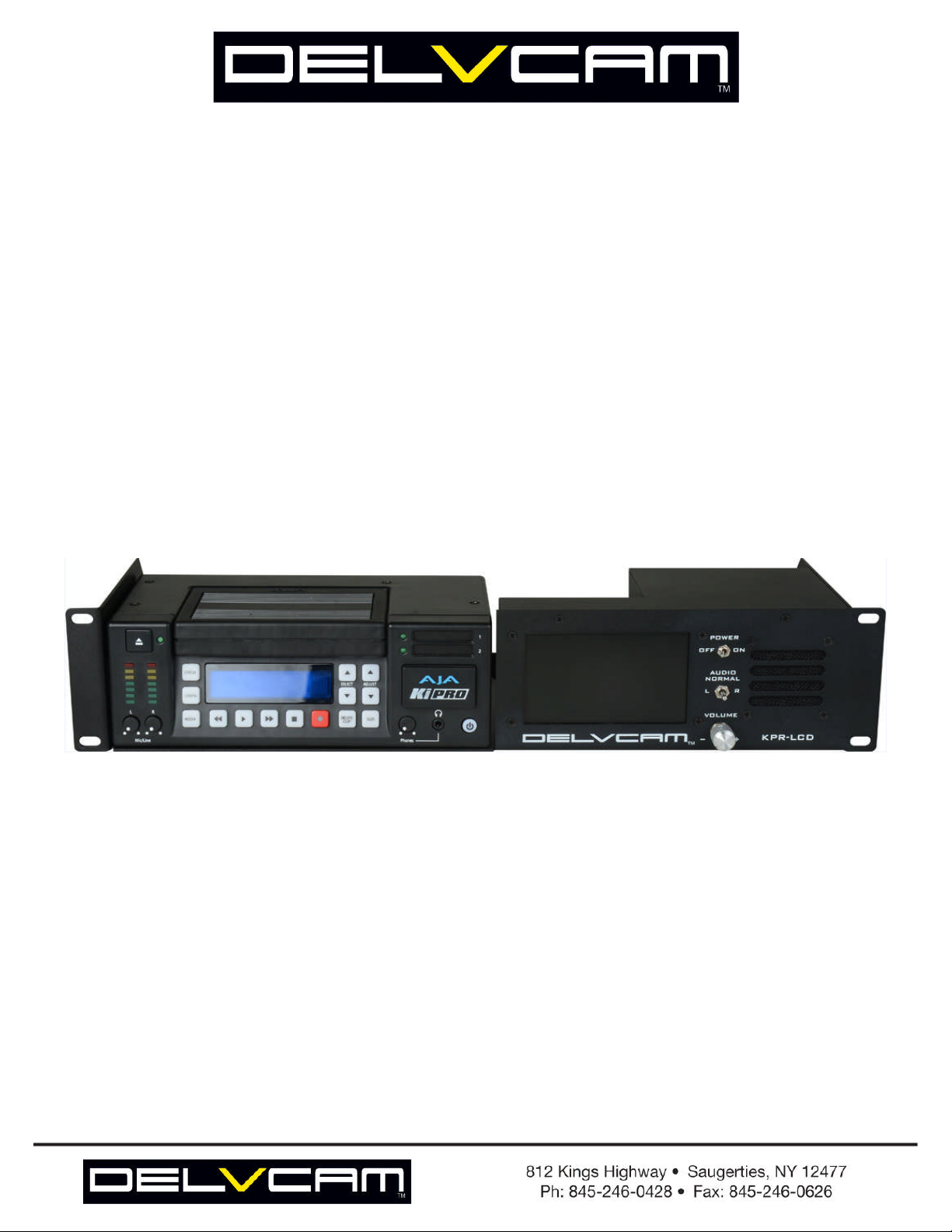
Delvcam KPR-LCD 2RU Rack Mount
with High Resolution LCD Monitor for AJA KiPro
USER MANUAL
Page 2

KPR-LCD
Delvcam KPR-LCD 2RU Rack Mount
with High Resolution LCD Monitor for AJA KiPro
Enhance Your AJA Ki-Pro With Advanced Monitoring Features!
The KPR-LCD is the perfect Solution for studio, field & fly packs! Securely mount your AJA full size Ki-Pro in
the Delvcam KPR-LCD 2RU rack mount with integrated high resolution LCD monitor with powerful audio monitor
functions. Gain the advantage of immediate monitoring of the Ki-Pro's Recording and Playback functions. Prevent
recording and audio phase and level errors with this functional unit.
Confidence monitor the audio from the Ki-Pro through the powerful integrated amplifier and speaker integrated in
the Delvcam KPR-LCD rack mount/monitor with Left-Right-Mute and volume controls.
Further, the Delvcam KPR-LCD rack mount/monitor uses the composite video and RCA connectors on the Ki-Pro so
the existing SDI, HDMI, Component Video and XLR Audio connectors are available for your other interface
requirements.
Features:
Video Monitoring: 480 x 234 LCD Panel
Audio Monitoring: 8-Watt Integrated Amp/Speaker
Independent L/R Muting
Audio Level Control
Specifications:
Ki-Pro not included
DELVCAM PART NUMBER: KPR-LCD
Page 3
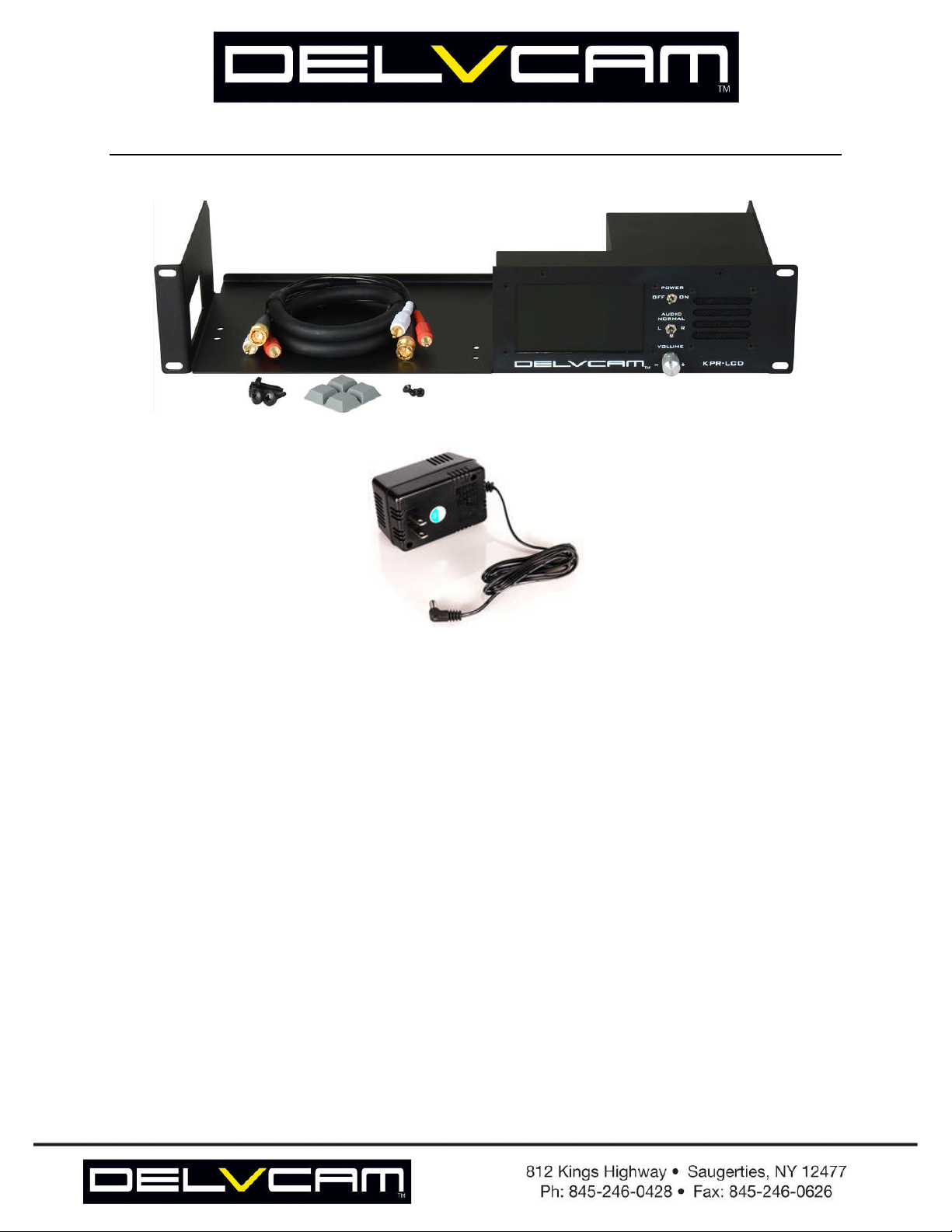
INCLUDED COMPONENTS WITH THE KPR-LCD:
1. The main unit with the rackmount and LCD with their relative controls for operation.
2. A high quality 2 RCA & 1 BNC jacketed and gold plated interface cable for connecting your KiPro
unit to the KPR-LCD.
3. Four large square gray rubber self-adhesive feet if this is to be used on a desktop.
4. Two 8-32 3/8” black flat head machine screws for securing your KiPro unit to the shelf space in the
rack mount.
5. Four 10-32 standard rack screws for mounting the assembly into youre standard equipment rack.
6. Business card congratulatory card with information and links to this manual.
7. 12VDC AC Power adapter with DC power plug (2.1mm barrel style) for powering the KPR-LCD
circuitry and LCD separately from the power for the KiPro unit itself
8. Environmentally conscious packaging materail to keep the KPR-LCD safe for transportation.
Page 4

INSTALLING YOUR KIPRO UNIT INTO THE KPR-LCD:
1. Carefully have your KiPro unit (KiPro) prepared and free of any connections before installing into the KPRLCD.
2. Remove the two 8-32 screws from the bottom of the unit that are the closest to the front, one is near the xlr
power input and the other is near the vent, both are on the bottom of the unit. Leave the two screws in the rear
corners of the unit in place, DO NOT REMOVE THE TWO BOTTOM REAR CORNER SCREWS.
3. With the KiPro still upside down, place the KPR-LCD over the unit so the holes line-up with the screw holes
from the screws that were just removed.
4. Please note there are two mounting sets of screws, -decide if you want the KiPro to be flush / even with the
front rack ears or forward / protruding and select the holes which will suit your selection.
5. Install the two 8-32 3/8” screws provided with your KPR-LCD through the KPR-LCD bottom and into the
KiPro screw holes and secure to a solid, hand-tightened tightness.
Page 5

POWERING THE UNIT:
1. Power for the LCD is a toggle switch labeled “POWER” and is located at the top right of the LCD screen,
This ONLY turns on and off the power to the LCD monitor.
2. Power for the audio section is operated by the initial click of the volume knob.
3. Having these two sections of the unit powered independantly allows the operator to only power what is
desired, whether it be the video monitor LCD or the audio amplifier and speaker, or both.
4. Once all power is connected and in the “on” position and the KiPro unit is setup to output CVBS and
ANALOG AUDIO OUT, the lcd will display the material from the KiPro and the Audio will be amplified and
played out of the speaker on the fron at the volume set by the volume knob accordingly. *Please reference the
KiPro user manual for the setting to enable the CVBS and the ANALOG AUDIO OUTPUT of the KiPro unit.
TWO WAYS TO MOUNT THE KIPRO UNIT:
--- FLUSH / EVEN ---
The KPR-LCD has mounting holes to mount your KiPro in either of two positions. Above the KiPro unit is
mounted so the front of the unit is flush, or even, with the front of the rack mount ears. Below it is mounted forward
apporximately 3/4" so-as the KiPro unit is protruding outwards, this mounting position fascilitates easier acces to the
hard drive cassette storage pack on the KiPro unit and makes ejecting and docking easier when the KPR-LCD is
installed into a rack populated with a lot of equipment.
--- FORWARD / PROTRUDING ---
Page 6

CONNECTING YOUR KIPRO UNIT TO THE KPR-LCD:
1. Once you have your KiPro installed into the KPR-LCD you are ready to connect the video and audio outputs
to the KPR-LCD monitoring system with the included high quality cable assembly.
2. Use the “CVBS” video output, this is a BNC connector and the unbalanced “ANALOG AUDIO OUT”, these
are the red and white RCA connectors on the back in the top right corner. Connect these corresponding inputs
of the KPR-LCD as shown below.
3. Use the picture below as a reference for connecting up your KiPro to the KPR-LCD connections:
4. Power for the KiPro unit can be plugged in and out without having to remove the KiPro unit from the rack
shelf; there is enough space to be able to do so by design.
5. Power will also need to be plugged into the KPR-LCD unit with the provided 2.1mm DC plug 12VDDC 2A
wall pack. As shown above this is on the back of the KPR-LCD housing labeled: “POWER 12 V 2 A”
6. And finally there are looping outputs for each input on the KPR-LCD. Each looping output is directly below
the corresponding input for use for forwarding the signal to other equipment as desired.
Page 7

SAFETY PRECAUTIONS
1. To prevent fire or shock hazard, do not expose this equipment to an environment
of high humidity and/or dust. Do not use in an unprotected outdoor installation or
any area classified as overly damp or wet.
2. The temperature for installation should be kept between 0°C ~ 60°C. Avoid direct
sunlight exposure or extreme changes of temperature over a short period of time.
3. Do not disassemble the unit or put it on an unstable base
4. Do not drop it and avoid heavy impact.
5. Ventilation: Any openings in the enclosure are provided for ventilation and to
ensure reliable operation of the unit and to protect it from overheating. These
openings, if any, must not be blocked or covered. This unit should not be placed in a
built-in installation unless proper ventilation is provided.
6. Cleaning: Unplug the unit from the mains outlet before cleaning. Do not use liquid
cleaners or aerosol cleaners, only use a damp cloth.
7. Do not overload outlets and extension cords as this may result in a risk of fire or
electric shock.
8. Enclosure Entry of any kind is dangerous. Never push objects of any kind,
including liquids, into this unit through openings as they may touch dangerous
voltage points or short-out parts that could result in a fire or electric shock.
9. Service: Do not attempt to open or service this unit yourself as opening or
removing covers may expose you to dangerous voltage of other hazards.
10. There are no user-serviceable parts inside the unit. If the unit requires service
please contact your authorized dealer, or an authorized repair service company.
Page 8

Notes:
________________________________________________________
________________________________________________________
________________________________________________________
________________________________________________________
________________________________________________________
________________________________________________________
________________________________________________________
________________________________________________________
________________________________________________________
________________________________________________________
________________________________________________________
________________________________________________________
________________________________________________________
 Loading...