

Page 1
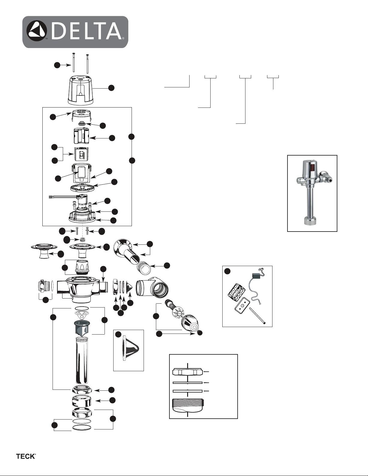
Electronic Exposed
®
TECK
210233 210233 210233 210233
(with H2Optics
II Flush Valves
™)
2
Record model number:
81T2__ 1__ __A - __ __ - __ __
3
5a
4
6
7a
7b
5b
1
10
a
10
b
11
b
12
9a
9b
8a
8b
10
c
11
a
14
Valve Type
0 = W/C (Water Closet)
2 = W/C - 22” outlet tube
3 = Urinal
19
20
18
Power Option
BT = Battery
HW = Hardwired
21
Additional Options
(leave blank if not applicable)
30 = w/Sloan ZurnTail
20 = Less Stop Assy
1 = V/B Tube w/Tee Assy (WC only)
30
Alternate Flush Volumes
(leave blank if not applicable)
6 = 6 litre (1.6 gal) fixed flush (WC only)
13 = 13 litre (3.4 gal) flush (WC Retrofit Kits only)
48 = 4.8 litre (1.27 gal) fixed flush (WC only)
38 = 3.8 litre (1.0 gal) fixed flush (Urinal only)
19 = 1.9 litre (0.5 gal) fixed flush (Urinal only)
05 = 0.5 litre (0.13 gal) fixed flush (Urinal only)
210233 210233 210233 210233
13
26
24
31
17
15
16
31
22
23
Slip Joint Nut Installation
Filter Screen
25
27
28
29
PLEASE LEAVE this M&I Sheet with the owner, maintenance plumber, etc. as items
Nut
Fibre Washer
Rubber Washer
For valves manufactured
after January 2013.
relating to ongoing maintenance suggestions and procedures are included.
www .specselect.com
210233 Rev. A
Page 2
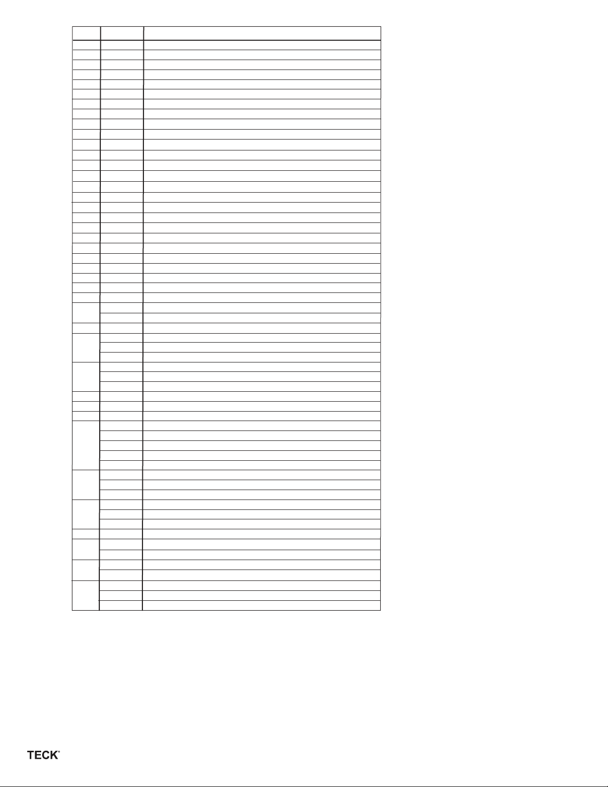
Item #
1 061063A
2 061138A
3 061139A
see #7
4
061140A Case Top for 3rd Generation E-FV
5a
5b 061170A
060334A
6
7a
061161A
7b
061162A
061024A
8a
8b
061169A Cast Cap/Solenoid & Regulating Screw Assembly
9a
061141A*
9b
060078A*
10a
060507A
062025A
10b
10c
060508A
11a
061216A**
11b
061217A**
11c
060079A
12
062007A**
060342A Plug & O-Ring for Handle End
13
060506A
14
060735A
15
060692A
16
060082A*
17
060504A
18
061142A
19
061143A
061144A
20
060697A
21
060694A
060764A
060843A
22
060844A
060859A
23
060081A*
060785A
24
060094A
25
060782A
26
060783A
060863A
060784A
060781A
060004A 1½” Spud Flange
27
060463A
060745A
060778A 1½” Rough Coupling Nut & Washer
28
060773A
060463A
060083A *
29
30
061069A
061069A-BB
060344A
31
060972A
060704A
060771A
060772A
DescriptionPart #
Replaceable Lens for 3rd Generation E-FV
Cover Screws for 3rd Generation E-FV
CP Metal Cover
Button Head Assembly
Plastic Case for 3rd Generation E-FV
Battery Holder
Water Closet Board for 3rd Generation E-FV & Override Button
Urinal Board for 3rd Generation E-FV & Override Button
Regulating Screw & O-Ring
Cover Gasket (3/pkg)
Screws for Cast Cap (4/pkg)
Poppet Pin Pack (3/pkg) (also see 10b)
Washer (3/pkg) (required for 6.0 & 4.8L Valves only)
Poppet Pin Pack (3/pkg) (0.5L Valves only)
Diaphragm/Guide Assembly Complete - WC
Diaphragm/Guide Assembly Complete - UR
Diaphragm Package
Brass Seat with O-Ring
Standard Adjustable Tail CP
Union Nut CP
Retaining Ring
Adjustable Tail O-Ring Package (20/pkg)
S/S Wall Flange & Cover Tube
Electronic Water Closet Repair Kit for 3rd Generation E-FV
Electronic Urinal Repair Kit for 3rd Generation E-FV
Electronic Water Closet Repair Kit for DF 3rd Generation E-FV
1” Copper Sweat Inlet Adaptor
¾” Copper Sweat Inlet Adaptor
¾” FIP Inlet Adaptor
Retrofit Check Stem Unit, Capnut & Button Complete
Seat Washer, Spring, Button & O-Ring Kit
Angle Stop with Union Nut & Tail Complete
Plug Button Package (12/pkg)
VB Sleeve Complete
CP Male Threaded Coupling Ring
1½” x 10” VB, Ring & Tube Complete (for 81T201)
1½” x 22¾” VB, Ring & Tube Complete (for 81T221)
1¼” x 10” VB, Ring & Tube Complete (for 81T291)
¾” x 11½” VB, Ring & Tube Complete (for 81T231)
1½” x 10” VB, Side Outlet Tee Tube Complete
¾” CP Coupling Nut, ¾” Washer & ¾” Spud Flange
1¼” Spud Flange
1¼” Rough Coupling Nut & Washer
¾” CP Coupling Nut, ¾” Washer & ¾” Spud Flange
1½” Rubber Slip Joint Washer (12/pkg)
Hardwire Converter & Rigid Connection Assembly for 3rd Gen E-FV
Hardwire Converter & Rigid Connection with Battery Back-up
Filter Screen Kit (12/pkg) for Teck tails
Filter Screen Kit (6/pkg) for Sloan
Transformer (110 to 24 VAC) for 5 Sensor Modules***
Transformer (110 to 24 VAC) for 10 Sensor Modules***
Transformer (110 to 24 VAC) for 25 Sensor Modules***
®
/Zurn® tails (-30 models)
* Package Quantities May Change. Check the parts section of the latest Delta Commercial Faucet Price List for current
quantities.
** For valves manufactured before January 2013, you must replace both 061216A/061217A diaphragm assembly and
062007A brass seat wih O-ring.
***Each individual sensor module requires its own 24 VAC to 6 VDC hardwire converter.
NOTE: Refer to TECK Flushometer Repair Parts and Maintenance Manual for additional
parts and information.
www .specselect.com
Page 2
210233 Rev. A
Page 3
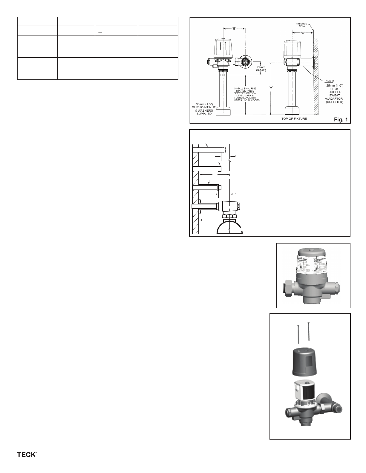
Product #
All 81T201BT/
81T201HW
variations*
A
Max.
B C
+ 11mm (
121mm (4¾”) 54mm (2.13”)292mm (11½”)
7
”
)
16
/
Min.
All 81T231BT/
330mm (13”)
121mm (4¾”) 54mm (2.13”)
81T231HW
variations*
* Note: -30 models, B = 114mm - 131 mm (4.5” to 5.18”)
BEFORE THE FIRST FLUSH (COMPLETE VALVES)
FLUSH BOTH OLD AND NEW PIPES:
It is important to FLUSH and CLEAN thoroughly both new and old
water piping to ELIMINATE contaminants (eg. scale, sediment, gravel,
cuttings, solder, etc.) from the line.
Where the water has a sediment content, a PIPE STRAINER in the
supply line should alleviate that condition and protect working parts of
flushometers and faucets.
On a NEW INSTALLATION, always flush the valve 4 or 5 times to
clean out supply line debris. It is also advisable where more than one
flushometer is installed on a water line, to flush out the water piping
through the last flushometer outlet of the pipe line.
INSTALL FILTER SCREEN (included):
Note: Place filter in stop bore with conical screen facing the water flow.
Caution: Do not push filter in too far. Let filter seat against face of flush
valve tail. Periodic cleaning of the filter screen with water is recommended depending on local water conditions to remove any dirt or
sediment. See filter screen M&I for additional installation information.
ELIMINATE AIR FROM VALVES:
The FIRST FLUSH should ELIMINATE all air from the TECK flushometer. DO NOT ADJUST flushometer based on the results of the first
flush.
1" Copper Inlet Supply
1" Copper Inlet Adapter Installation
Adapter
"D"
Cover Tube
Finished
Wall
25mm
(1")
38mm
(1½”)
Of Fixture Spud
1. Measure distance “D” from centre line
of fixture spud to finished wall.
2. Cut copper tube 1” shorter than
dimension “D”.
3. Push adapter onto copper tube until it
stops on the shoulder.
4. Solder adapter to copper tube.
5. Cut cover tube 1½” shorter than
dimension “D”.
6. Slide the wall flange and cover tube
over the supply pipe.
7. Thread the union stop onto the adapter,
and tighten set screw in flange.
Fig. 2
TO PREVENT WATER HAMMER:
A water hammer arrestor may be installed at the last flushometer and/or at the back of an individual
installation. This assures SMOOTHER OPERATION of the valves and longer life for the working parts.
HANDS SHOULD BE CLEAN AND FREE OF GREASE AND OIL during any maintenance or handling of
electronic housing components to prevent possible damage to internal circuitry.
IF LEFT HAND STOP REQUIRED:
• Remove the chrome cover by taking out the two cover screws. See Figure 4.
• You will now see the clear electronic compartment with a grey cover.
• Now take hold of the compartment and very carefully, slowly lift the compartment about 1/4” and turn it
180°.
• The sensor eye should now be on the other side.
• Gently push the compartment back down, aligning the two screw holes on the clear case with the
screw holes on the brass solenoid cap.
• Rotate cover gasket 180° on brass cap.
• Check for pinched wires between cover and clear case.
• Ensure grey cover is snapped onto clear case and chrome button is properly seated.
• Replace the chrome cover and two cover screws - do not overtighten cover screws.
Flush volume adjustment:
3.43 U.S. gallons / 13.0 litres for water closets
1.60 U.S. gallons / 6.0 litres for water closets
1.27 U.S. gallons / 4.8 litres for water closets
1.0 U.S. gallon / 3.8 litres for urinal valves
0.5 U.S. gallon / 1.9 litres for urinal valves
0.13 U.S. gallon / 0.5 litre for urinal valves
The Regulating Screw (061024A, item #8) may be adjusted, according to job conditions and fixture
installed to the proper water volume to flush that particular fixture (except -6, -48, -38, -19 and -05
models which are not field adjustable).
NOTE: 4.8 and 6 Litre water closets or washdown urinals may require the Angle Stop to be set at only
ONE TURN OPEN. For a SHORTER flush, turn the Regulating Screw (061024A, item #8) left
(counter-clockwise) and right (clockwise) for a LONGER flush (except -6, -48, -38, -19 and -05 models
which are not field adjustable).
Fig. 3
Fig. 4
www .specselect.com
Page 3
210233 Rev. A
Page 4

INSTALLATION INSTRUCTIONS - BATTERY FLUSHOMETER
(for Hardwire, skip to Step 3)
Step 1:
• Install battery flushometer to fixture.
• Open inlet stop.
Step 2:
• Follow instructions on yellow static label (Figure 3). Note: The batteries are already installed and the product is in hibernation mode
waiting to be activated.
• After you remove the yellow label, you must push the manual over-ride button three times within five seconds to activate the valve and to
place it into operation mode. To signify the valve has entered operation mode, you will see an ascending and descending light sequence.
• Proceed to Step 5.
INSTALLATION INSTRUCTIONS - HARDWIRED FLUSHOMETER
Step 3:
• Before installing the flush valve body. Install 2” x 4” electrical box into wall with centre of box in line with the cut-out in the back of the
metal flush valve cover. See Figure 5.
• Securely attach box to wall structure. Install CSA and/or UL approved Class 2 transformer
or equivalent in a convenient location or in a pipe chase. (Do NOT install the transformer
inside the control box.) Run suitable wires from 24 VAC step down transformer into the
electrical box. The transformer is to be installed in an adjacent accessible space. Use cable
which complies to local electrical codes for 1 amp load. No. 18 cable is usually sufficient.
• Assemble plastic bushing into the hole on the coverplate.
• Measure and cut tube assembly to appropriate length so that the bushing will fit under the
metal flush valve cover and the free end will protrude into the box through the coverplate by
1/2” minimum. Rotate cover gasket, if necessary, so that the U-shaped wire guides align with
the rear opening in valve cover.
• Assemble flush valve to fixture. When ready, remove metal cover and feed the wires from
the hardwire converter through the tube assembly and the tube assembly through the bushing
on the coverplate.
• Attach the converter wires to the 24 VAC wires from a step down transformer.
• With power to the flushometer, you will see an ascending and descending light sequence to
signify that the valve is now in operation mode.
• Assemble coverplate using the bracket and screws provided.
• With the tube bushing located in position, assemble metal cover to flush valve body with tube assembly located in metal cover cut-out.
NOTE:
Hardwire junction box installed behind
flush valve on the centreline of fixture.
Fig. 5
Step 4:
• Open inlet stop.
Step 5: Operation Mode
Upon power up - a sequence of descending and ascending red lights will signify that the valve is in operation mode.
Once in operation mode, if factory settings are preferred, no further action is required and the valve installation is complete.
Factory pre-set functions are:
WC bowl length of 24”, 24 hour flush is off.
Urinal sensing distance of 16”, 24 hour flush is off.
MAKING ADJUSTMENTS TO THE ELECTRONIC FEATURES
(Optional: Only required if factory settings are not preferred)
Once in operation mode, if adjustments are preferred, installer must move into set up mode.
If desired adjustments are not made within 30 minutes of initial power-up, the power must be disconnected for 10 seconds and
then reconnected to obtain another adjustment period.
Step 6: Set-Up Mode
• If 30 minutes have passed since the initial power-up of the valve - open up the battery compartment (Figures 9 and 10) and disconnect the
battery snap for 10 seconds. Reconnect and replace the chrome cover and screws. If hardwired - disconnect battery snap to the hardwire
converter for 10 seconds.
• To move from operation mode into set-up mode, push and hold manual override button for five seconds. Release the override button
when a solid blue light is visible.
• The watercloset flushometer models have 2 settings which are adjustable via the Set-Up Mode - Bowl Length Selection and 24
Hour Flush Adjustment.
• The urinal flushometer models have 2 settings which are adjustable via the Set-Up Mode - Range Adjustment and 24 Hour Flush
Adjustment.
• While in Set-Up Mode, the user will move through the different adjustment modes one by one, in the order as described above. Use the
override button to toggle through the different settings of the adjustment feature being altered. To advance to the next adjustment mode,
hold down override button until blue light is present, then release the button. See Figure 6.
www .specselect.com
Page 4
210233 Rev. A
Page 5

ENTER SETUP MODE
Bowl Length
TO ENTER SETUP MODE - HOLD DOWN
OVERRIDE BUTTON UNTIL BLUE LIGHT
PRESENT. RELEASE BUTTON.
EXIT SETUP MODE
TO EXIT SETUP AND RETURN TO
OPERATION MODE - HOLD DOWN
OVERRIDE BUTTON UNTIL BLUE
LIGHT PRESENT. RELEASE BUTTON.
HOLD DOWN OVERRIDE
BUTTON UNTIL SOLID
BLUE LIGHT PRESENT
TO ADVANCE RELEASE
BUTTON.
HOLD DOWN OVERRIDE
BUTTON UNTIL SOLID
BLUE LIGHT PRESENT
TO ADVANCE RELEASE
BUTTON.
Fig. 6
▼ ▼ ▼
7.1 SENSOR RANGE ADJUSTMENT MODE
- Press and release override to toggle through the
settings
- Blue light flashes when object is detected
- Red lights signify range choices
Lights visible
1 Red
2 Reds
3 Reds
4 Reds
5 Reds
W/C Bowl
Length
20”
22”
24”
26”
28”
Urinal
Sensing Distance
8”
12”
16”
20”
24”
(WC only - designed for future options)
INACTIVE MODE
Step 7: Making Adjustments (Optional: Only required if factory settings are not preferred)
7.1 Sensor Adjustment:
For Waterclosets:
• Configure the sensing ranges by selecting the appropriate bowl length. Refer to Figure 6 for the
different bowl length settings.
• The bowl length is the distance from the centre line of the valve to the lip of the bowl (see Figure 7).
• To ensure the correct distance is selected, stand or place a target at the end of the bowl. Starting
with one illuminated red light, step through the distances until the blue light begins to flash.
The flashing light confirms that the sensor is configured for that bowl length.
• NOTE the WC bowl length setting is NOT the sensing range. The advanced sensor activated flush
system uses multiple detection distances and the bowl length to react appropriately to different
usage patterns.
• If no further length adjustments are desired, press and hold down the override button for 5 seconds,
until a solid blue light is present. Release the override button to advance to the next adjustment
feature.
• A blue and red light will be present. This mode is currently inactive and is designed for any future options.
• To advance to the 24 Hour Flush, press and hold down override button for 5 seconds until the solid blue light is present.
• Release override button, you are now in 24 Hour Flush configuration.
For Urinals:
• Configure the sensing range by selecting the desired detection distance.
• Each press and release of the override button advances to the next length/distance. (See Figure 6 for a list of distances.)
• Start with one red visible light.
• Stand or place a target at the desired detection distance, the top blue light will be flashing if an object is detected.
• Press and release override button to step through the distance options until the blue light begins to flash, indicating that the target
has been detected. The blinking blue light indicates that the sensor is configured for that length/distance.
• The sensor is now set at your desired configuration.
• If no further sensing range adjustments are desired, press and hold down the override button for 5 seconds, until a solid blue light
is present.
• Release override button, you are now in 24 Hour Flush configuration.
7.2 24 HOUR FLUSH ADJUSTMENT
- Press and release override to toggle through the
settings
- No Blue light will be present
- Red lights signify 24 Hour flush on or off
Lights visible
2 Reds 24 Hour Flush OFF
3 Reds 24 Hour Flush ON
Fig. 7
7.2 24 Hour Flush Adjustment Mode:
• When the 2 red lights are present - 24 hour flush is OFF.
• When the 3 red lights are present - 24 hour flush is ON.
• Press manual override button to toggle between ON and OFF mode.
www .specselect.com
Page 5
210233 Rev. A
Page 6

Exiting Set-Up Mode:
• Can be accomplished in one of two ways;
1. During the 24 Hour Adjustment feature, press and hold down override button for 5 seconds until solid blue light is present. Release
override button.
2. During all modes, valve will revert back to operation mode automatically if the override button is not pressed within 2 minutes.
* After the last adjustment has been completed and the flush valve has returned to operation mode, there is a window of
approximately 30 minutes where additional changes can be made. If desired adjustments are not made within 30 minutes,
the batteries or hardwire converter must be disconnected for 10 seconds and then re-connected to obtain another adjustment
period. To make changes, begin at step #6 above.
BATTERY STRENGTH INDICATOR & BATTERY REPLACEMENT
TO CHECK BATTERY STRENGTH:
1. During Operation Mode - press and hold down the override button for approximately 10 seconds.
2. DO NOT RELEASE BUTTON WHEN SOLID BLUE LIGHT IS PRESENT - KEEP HOLDING DOWN.
3. After 10 seconds, the battery strength will be displayed via the red lights. The more lights that are
present, the more life the batteries have. See Figure 8.
4. When you are satisfied with the strength indication, release the override button to return to Operation
mode.
BATTERY STRENGTH INDICATION
VERY HEALTHY - 5 RED LIGHTS
HEALTHY - 4 RED LIGHTS
AVERAGE - 3 RED LIGHTS
LOW AVERAGE - 2 RED LIGHTS
REPLACE BATTERIES - 1 RED LIGHT
Fig. 8
TO REPLACE BATTERIES:
1. Remove the two cover screws and lift off CP metal cover, see Figure 9.
2. Hold case/cover securely with one hand and open hinged lid of the battery
compartment in the back of the unit.
3. Pull the battery holder out and insert new set of four “AA” batteries into battery
holder. (Use the +/- signs on the batteries and the +/- signs on the battery holder
for correct positioning.) Note: Do not use a metal screwdriver to remove snap
from battery holder.
4. Install the refreshed battery holder back into the electronic housing. (When the
new batteries are installed and connected, an initial ascending and descending
red light sequence will occur.)
5. Close the battery compartment lid ensuring wires are neatly tucked into compart ment and are not pinched between case and cover. Test the manual override
button. Blue light flashes once when override is activated.
6. Place the CP metal cover back onto flushometer and replace the two cover
screws. DO NOT OVERTIGHTEN. Flushometer is now ready for use.
* NOTE: All previously adjusted settings will be retained when batteries are
changed.
1. Start-Up: When batteries are first inserted, there is an initial ascending and
descending red light sequence that will occur.
2. Override Button in Operating Mode: Blue light flashes once when Override
Button is activated.
3. Low Battery Level Indicator: One RED light flashes every 15 seconds,
indicating approximately 5,000 flushes remain from when RED light first started
flashing.
Fig. 9
Fig. 10
www .specselect.com
Page 6
210233 Rev. A
Page 7

PROBLEM SOLVING & MAINTENANCE SUGGESTIONS:
NO LIGHTS - NO POWER
Check that the 4 “AA” batteries are positioned properly in the battery holder. Use the +/- signs on the batteries and the +/- signs on the battery
holder for correct positioning.
If the batteries are positioned correctly, but there are still no lights, replace with 4 new “AA” Alkaline batteries (see Battery Replacement on page 6).
NOTE: DO NOT USE EXCESSIVE FORCE to close the inlet stop stem. We RECOMMEND that the fllushometer be flushed while closing the inlet
stop. The noise created by the water flow or the flow into the fixture will stop when the inlet water is shut off.
NOTE: Always use DELTA COMMERCIAL GENUINE PARTS to maintain the warranty.
EXCESSIVE NOISE:
1. PARTIALLY close the inlet stop.
2. Pressures OVER 75 PSI may lead to an increase in NOISE, water could SPLASH out of the fixture more easily and the LIFE of any plumbing
valve may be SHORTENED.
3. INSTALL a Pressure Reducing Valve set at a lower pressure if actual pressure is over 75 PSI. While the TECK Flushometer will operate up to
125 PSI, the preferred operating range is between 35 to 65 PSI.
4. On flushometers that have been installed for a number of years, check the Renewable Seat (062007A, item #12) for wear and replace if necessary.
EXCESSIVE WATER FLOW RATE:
1. OPEN inlet stop ONE TURN and adjust Regulating Screw (061024A, item #8a) to the fixture requirement (except on -6, -38, -19, -05 and -48 models
which are fixed volume).
2. Operation of flushometer with inlet stop BELOW ONE TURN OPEN may cause EXCESSIVE NOISE. The lowest open setting for the inlet stop
may vary dependent on the installation.
SHORTAGE OF WATER TO PROPERLY FLUSH BOWL:
1. OPEN inlet stop fully.
2. CHECK pipeline for size or obstruction, partially closed gate or other supply line valve, corroded or undersize water piping.
3. CHECK water pressure.
4. Water flow rate is determined by BOTH the water pipe size AND the water pressure available.
5. A water closet flush valve requires a minimum water supply of 1” (or larger), depending on a number of different factors including water pressure
(PSI) available, pipe size and length of pipe run, number of fixtures per washroom and per building, fixture type, fixture usage factor, elevation of
valve above the water main, etc. We strongly recommend that pipe size calculations be done to insure proper water supply sizes. A Piping
Calculation Guide is available on request.
Flushometers do NOT provide a water supply; they are merely automatically timed self-closing valves. The inlet supply piping is the water reservoir
that must supply sufficient water volume in a short period of time (4 to 10 seconds) to properly flush and clear the fixture.
CONTINUOUS FLUSHING:
1. The Regulating Screw (061024A, item #8a) may be turned RIGHT (clockwise) TOO FAR. Adjust by slowly turning the Regulating Screw LEFT
(counter-clockwise). (Except -6, -48, -38, -19 and -05 models which are fixed volume).
2. If flush is still continuous, remove 061024A Regulating Screw, CLEAN bypass slot in the Screw, REPLACE it in the valve and ADJUST slowly for
proper flush (except -6, -48, -38, -19 and -05 models which are fixed volume).
3. Remove cast cap assembly and Diaphragm/Guide Assembly (061216A - WC or 061217A - UR, item #11), check for contaminants at renewable
seat and diaphragm and check for debris in the cap for blockage. Also CHECK that the Diaphragm/Guide slides easily in the Renewable Seat.
VALVE WILL NOT FLUSH:
1. When the valve has been taken apart for servicing and re-assembled and does NOT operate, check that the Cast Cap has been put on the body
properly. The Regulating Screw (061024A, item #8a) should always be on the same side as the inlet stop.
2. When all lights operate as expected but valve will not flush, check that the solenoid makes a clicking sound. If no clicking sound is present, then
replace with Electronic Repair Kit (WC - 061142A or UR - 061143A, item #19).
3. After a number of years, the valve will flush but shuts off immediately when activated. The Diaphragm (060079A, item #11c) is worn or split and
needs replacing.
SLIGHT WATER LEAK INTO FIXTURE:
1. EXAMINE the seating surface of the Diaphragm (060079A, item #11c) for imbedded sediment.
CLEANING INSTRUCTIONS:
CLEAN the outside of the chrome plated flushometer with a damp cloth.
CAUTION: MOST Tub & Tile fixture cleaners contain ACIDS. DO NOT WIPE the cloth used to clean ceramic fixtures over the flushometer as it will
remove the chrome plating and leave a discoloured surface.
For a copy of the “TECK Flushometer Maintenance Manual/Piping Calculation Guide”, contact your local Delta Representative.
www .specselect.com
Page 7
210233 Rev. A
Page 8

Delta Commercial Faucet Limited Warranty
All parts of the Delta® HDF® and TECK® faucets are warranted to the original consumer purchaser to be free from defects in material, finish and workmanship for a period of
five (5) years unless otherwise specifically stated in the catalogue and price book. This warranty is made to the original consumer purchaser and shall be effective from date
of purchase as shown on purchaser’s receipt.
Delta will, at its option, repair or replace, FREE OF CHARGE, during the warranty period, any part which proves defective in material or workmanship under normal installation,
use and water and service conditions. If Delta Faucet concludes that the returned part was manufactured by Delta Faucet and is, in fact, defective, then Delta Faucet will
honour the warranty stated herein. Replacement parts can be obtained from your local dealer or distributor listed in the telephone directory or by returning the part along
with the purchaser’s receipt to our factory, TRANSPORTATION CHARGES PREPAID, at the address listed. THIS WARRANTY IS THE ONLY EXPRESS WARRANTY MADE BY DELTA.
ANY CLAIMS MADE UNDER THIS WARRANTY MUST BE MADE DURING THE FIVE YEAR PERIOD REFERRED TO ABOVE. ANY IMPLIED WARRANTIES, INCLUDING THE IMPLIED
WARRANTY OF MERCHANTABILITY OF FITNESS FOR A PARTICULAR PURPOSE, ARE LIMITED IN DURATION TO THE DURATION OF THIS WARRANTY. LABOUR CHARGES AND/OR
DAMAGE INCURRED IN INSTALLATION, REPAIR OR REPLACEMENT AS WELL AS INCIDENTAL AND CONSEQUENTIAL, SPECIAL, INDIRECT OR PUNITIVE DAMAGES CONNECTED
THEREWITH ARE EXCLUDED AND WILL NOT BE PAID BY DELTA FAUCET.
Some states do not allow limitations on how long an implied warranty lasts, or the exclusion or limitation of incidental or consequential damages, so the above limitations or
exclusions may not apply to you. This warranty gives you specific legal rights, and you may also have other rights which vary from state to state.
This warranty is for commercial products only from Delta Faucet Company and Delta Faucet Canada (a division of Masco Canada Limited) and is void for any damage to this
faucet due to misuse, abuse, neglect, accident, improper installation, any use in violation of instructions furnished by Delta Faucet or any use of replacement parts other than
genuine Delta parts.
Garantie Limitée Delta Commercial
Toutes les pièces des robinets de marque Delta® HDF® et TECK® sont garanties contre tout défaut de matériel, de finition et de main-d’oeuvre pour une période de cinq (5)
ans, sauf indication contraire stipulée dans le catalogue et la liste des prix. Cette garantie est offerte à l’acheteur original et entre en vigueur à compter de la date d’achat
indiquée sur la preuve d’achat.
Delta procédera, à son entière discrétion, à la réparation ou au remplacement, SANS FRAIS, durant la période de garantie, de toute pièce qui présente un défaut de matériel
ou de main-d’oeuvre dans des conditions d’installation, d’usure, d’eau et de service normales. Si Delta Faucet détermine que la pièce retournée a été fabriquée par Delta
Faucet et qu’en effet, cette pièce défectueuse, Delta Faucet respectera alors la garantie mentionnée ci-dessous. Les pièces de rechange peuvent être obtenues chez votre
marchand local ou le distributeur inscrit dans votre annuaire téléphonique, ou en retournant la pièce ainsi que la preuve d’achat à notre usine, FRAIS DE TRANSPORT
PRÉPAYÉS, à l’adresse indiquée. CET TE GARANTIE EST LA SEULE GARANTIE EXPRESSE FAITE PAR DELTA.
TOUTE RÉCLAMATION FAITE EN VERTU DE CETTE GARANTIE DOIT ÊTRE PRÉSENTÉE DURANT LA PÉRIODE DE CINQ ANS MENTIONNÉE CI-DESSUS. TOUTE GARANTIE IMPLICITE,
Y COMPRIS LA GARANTIE IMPLICITE DE VALEUR COMMERCIALE D’ADÉQUATION POUR UN USAGE PARTICULIEUR, EST LIIMITÉE DANS LE TEMPS À LA DURÉE DE LA PRÉSENTE
GARANTIE.
LES FRAIS DE MAIN-D’OEUVRE ET/OU LES DOMMAGES ENCOURUS DURANT L’INSTALLATION, LA RÉPARATION OU LE REMPLACEMENT AINSI QUE LES DOMMAGES ACCIDENTELS ET CONSÉCUTIFS, SPÉCIAUX, INDIRECTS OU PUNITIFS QUI SONT RELIÉS SONT EXCLUS ET NE SERONT PAS PAYÉS PAR DELTA FAUCET.
Certains états ne permettent pas la limitation de la durée de la garantie implicite, ou l’exclusion ou la limitation des dommages accidentels ou consécutifs, et par conséquent,
les limitations ou les exclusions stipulées ci-dessus peuvent ne pas s’appliquer dans votre cas. Cette garantie vous accorde certains droits reconnus par la loi et vous pouvez
aussi avoir d’autres droits qui varient d’un état à l’autre.
Cette garantie s’applique seulement aux produits commerciaux de Delta Faucet Company et Delta Faucet Canada (une filiale de Masco Canada Limited) et est nulle de plein
droit pour tout dommage causé à ce robinet en raison d’une mauvaise utilisation, d’abus, de négligence, d’accident, de mauvaise installation, pour tout usage en contravention des directives fournies par Delta Faucet ou pour tout usage de pièces de rechange autres que des pièces originales Delta.
Garantía Limitada de las Llaves de Agua Comerciales Delta
Todas las piezas de las llaves de agua (grifos) Delta® HDF®, TECK® están garantizadas al comprador consumidor original de estar libres de defectos de material, acabado y
fabricación por un periodo de cinco (5) años a menos que sea establecido específicamente de otra manera en el catálogo o libro de precios. Esta garantía se le otorga al
comprador consumidor original y será efectiva desde la fecha de compra indicada en el recibo del comprador.
Delta, a su opción, reparará o reemplazará, GRATUITAMENTE, durante el periodo de garantía, cualquier pieza que resulte defectuosa en material o fabricación bajo
instalación, uso, agua y condiciones de servicio normales. Si Delta Faucet concluye que la pieza devuelta fue fabricada por Delta Faucet y es, de hecho, defectuosa, entonces
Delta Faucet honrará la garantía establecida en este documento.
Las piezas de reemplazo se pueden obtener de su tienda o distribuidor local listado en la guía telefónica o devolviendo la pieza junto con el recibo de compra a nuestra
fábrica, CON LOS GASTOS DE ENVÍO PRE-PAGADOS, a la dirección indicada. ESTA GARANTÍA ES LA ÚNICA GARANTÍA EXPRESA HECHA POR DELTA. CUALQUIER RECLAMO
HECHO BAJO ESTA GARANTÍA DEBE SER HECHO DURANTE EL PERÍODO DE CINCO AÑOS ARRIBA MENCIONADO. CUALQUIER GARANTÍA IMPLÍCITA, INCLUYENDO LA
GARANTÍA IMPLÍCITA DE COMERCIABILIDAD DE EMPLEO PARA UN PROPÓSITO PARTICULAR, TIENE UNA DURACIÓN LIMITADA A LA DURACIÓN DE ESTA GARANTÍA. LOS
CARGOS DE MANO DE OBRA Y/O DAÑO INCURRIDO DURANTE LA INSTALACIÓN, REPARACIÓN O REEMPLAZO, COMO TAMBIÉN DAÑOS INCIDENTALES O RESULTANTES,
ESPECIALES, INDIRECTOS O PUNITIVOS RELACIONADOS CON LO MENCIONADO, QUEDAN EXCLUIDOS Y NO SERÁN CUBIERTOS POR DELTA FAUCET.
Algunos estados no permiten limitaciones de la duración de una garantía implícita, o la exclusión o limitación de daños incidentales o consecuentes, de manera que las
limitaciones o exclusiones arriba mencionadas puedan no aplicarse en su caso. Esta garantía le otorga derechos legales específicos, y usted también puede tener otros
derechos que varían de estado a estado.
Esta garantía es solo para productos comerciales de Delta Faucet Company y Delta Faucet Canada (una división de Masco Canada Limited), y queda anulada por cualquier
daño ocasionado a esta llave de agua resultante del mal uso, abuso, descuido, accidente, instalación incorrecta, cualquier uso en violación de las instrucciones proporcionadas
por Delta Faucet o el uso de cualquier parte de repuesto que no sea una parte genuina de Delta.
Delta Faucet Canada, a division of Masco Canada Limited
350 South Edgeware Road, St. Thomas, Ontario, N5P 4L1
1-800-567-3300 (English) 1-800-265-9245 (French)
For further technical assistance, call Delta Commercial Technical Service at 1-800-387-8277.
Pour obtenir de l’assistance technique, appelez le Service Technique de Delta Commercial au 1-800-387-8277.
Por la asistencia técnica adicional, llame al servicio técnico de Delta Comercial al 1-800-387-8277.
Delta Faucet Company
Box 40980, 55 East 111th St., Indianapolis, IN, U.S.A. 46280
(317) 848-1812
www.deltacommercialfaucets.com
Page 8
210233 Rev. A
 Loading...