

Page 1
Page 2
Page 3

Page 4

Preface
Thank you for choosing DELTA’s high-performance VFD-VL Series. The VFD-VL Series is
manufactured with high-quality components and materials and incorporates the latest
microprocessor technology available.
This manual is to be used for the installation, parameter setting, troubleshooting, and daily
maintenance of the AC motor drive. To guarantee safe operation of the equipment, read the
following safety guidelines before connecting power to the AC motor drive. Keep this operating
manual at hand and distribute to all users for reference.
To ensure the safety of operators and equipment, only qualified personnel familiar with AC motor
drive are to do installation, start-up and maintenance. Always read this manual thoroughly before
using VFD-VL series AC Motor Drive, especially the WARNING, DANGER and CAUTION notes.
Failure to comply may result in personal injury and equipment damage. If you have any questions,
please contact your dealer.
PLEASE READ PRIOR TO INSTALLATION FOR SAFETY.
DANGER!
1. AC input power must be disconnected before any wiring to the AC motor drive is made.
2. A charge may still remain in the DC-link capacitors with hazardous voltages, even if the power
has been turned off. To prevent personal injury, please ensure that power has turned off before
opening the AC motor drive and wait ten minutes for the capacitors to discharge to safe voltage
levels.
3. Never reassemble internal components or wiring.
4. The AC motor drive may be destroyed beyond repair if incorrect cables are connected to the
input/output terminals. Never connect the AC motor drive output terminals U/T1, V/T2, and
W/T3 directly to the AC mains circuit power supply.
5. Ground the VFD-VL using the ground terminal. The grounding method must comply with the
laws of the country where the AC motor drive is to be installed. Refer to the Basic Wiring
Diagram.
6. VFD-VL series is used only to control variable speed of 3-phase induction motors, NOT for 1-
phase motors or other purpose.
7. VFD-VL series shall NOT be used for life support equipment or any life safety situation.
Page 5

WARNI NG!
1. DO NOT use Hi-pot test for internal components. The semi-conductor used in AC motor drive
easily damage by high-voltage.
2. There are highly sensitive MOS components on the printed circuit boards. These components
are especially sensitive to static electricity. To prevent damage to these components, do not
touch these components or the circuit boards with metal objects or your bare hands.
3. Only qualified persons are allowed to install, wire and maintain AC motor drives.
CAUTION!
1. Some parameters settings can cause the motor to run immediately after applying power.
2. DO NOT install the AC motor drive in a place subjected to high temperature, direct sunlight,
high humidity, excessive vibration, corrosive gases or liquids, or airborne dust or metallic
particles.
3. Only use AC motor drives within specification. Failure to comply may result in fire, explosion or
electric shock.
4. To prevent personal injury, please keep children and unqualified people away from the
equipment.
5. When the motor cable between AC motor drive and motor is too long, the layer insulation of the
motor may be damaged. Please use a frequency inverter duty motor or add an AC output
reactor to prevent damage to the motor. Refer to appendix B Reactor for details.
6. The rated voltage for AC motor drive must be ≤ 240V (≤ 480V for 460V models) and the mains
supply current capacity must be ≤ 5000A RMS (≤10000A RMS for the ≥ 40hp (30kW) models)
Page 6

Table of Contents
Preface ............................................................................................................. i
Table of Contents .......................................................................................... iii
Chapter 1 Introduction................................................................................ 1-1
1.1 Receiving and Inspection ...................................................................1-2
1.1.1 Nameplate Information................................................................ 1-2
1.1.2 Model Explanation ...................................................................... 1-2
1.1.3 Series Number Explanation ........................................................ 1-3
1.1.4 Drive Frames and Appearances ................................................. 1-3
1.1.5 Drive Features ............................................................................ 1-5
1.2 Preparation for Installation and Wiring ............................................... 1-6
1.2.1 Ambient Conditions..................................................................... 1-6
1.2.2 Remove Front Cover................................................................... 1-7
1.2.3 Lifting .......................................................................................... 1-8
1.2.4 Flange Mounting ......................................................................... 1-9
1.2.5 Cutout Dimensions.................................................................... 1-11
1.3 Dimensions....................................................................................... 1-13
Chapter 2 Installation and Wiring ..............................................................2-1
2.1 Wiring ................................................................................................. 2-1
2.2 External Wiring ................................................................................... 2-6
2.3 Main Circuit ........................................................................................2-7
Page 7

2.3.1 Main Circuit Connection .............................................................. 2-7
2.3.2 Main Circuit Terminals................................................................. 2-9
2.4 Control Terminals .............................................................................2-10
Chapter 3 Operation and Start Up ..............................................................3-1
3.1 Operation Method ...............................................................................3-1
3.2 Trial Run .............................................................................................3-3
3.3 Auto-tuning Operations .......................................................................3-4
3.3.1 Flow Chart...................................................................................3-4
3.3.2 Explanations for the Auto-tuning Steps ....................................... 3-5
3.3.2.1 Step 1 .................................................................................. 3-5
3.3.2.2 Step 2 .................................................................................. 3-7
3.3.2.3 Step 3 .................................................................................. 3-9
3.3.2.4 Step 4 ................................................................................ 3-11
3.3.2.5 Step 5 ................................................................................ 3-13
3.3.2.6 Step 6 ................................................................................ 3-13
Chapter 4 Parameters..................................................................................4-1
4.1 Summary of Parameter Settings......................................................... 4-2
4.2 Description of Parameter Settings ....................................................4-20
Chapter 5 Troubleshooting.........................................................................5-1
5.1 Over Current (OC) ..............................................................................5-1
5.2 Ground Fault.......................................................................................5-2
5.3 Over Voltage (OV) ..............................................................................5-2
5.4 Low Voltage (Lv).................................................................................5-3
5.5 Over Heat (OH)...................................................................................5-4
5.6 Overload ............................................................................................. 5-4
Page 8

5.7 Display of KPVL-CC01 is Abnormal ................................................... 5-5
5.8 Phase Loss (PHL) ..............................................................................5-5
5.9 Motor cannot Run............................................................................... 5-6
5.10 Motor Speed cannot be Changed..................................................... 5-7
5.11 Motor Stalls during Acceleration....................................................... 5-8
5.12 The Motor does not Run as Expected .............................................. 5-8
5.13 Electromagnetic/Induction Noise ...................................................... 5-9
5.14 Environmental Condition ..................................................................5-9
5.15 Affecting Other Machines ............................................................... 5-10
Chapter 6 Fault Code Information and Maintenance................................ 6-1
6.1 Fault Code Information....................................................................... 6-1
6.1.1 Common Problems and Solutions............................................... 6-2
6.1.2 Reset .......................................................................................... 6-9
6.2 Maintenance and Inspections........................................................... 6-11
Appendix A Specifications ........................................................................ A-1
Appendix B Accessories ........................................................................... B-1
B.1 All Brake Resistors & Brake Units Used in AC Motor Drives..............B-2
B.1.1 Dimensions and Weights for Brake Resistors ............................ B-4
B.1.2 Specifications for Brake Unit ......................................................B-6
B.1.3 Dimensions for Brake Unit..........................................................B-7
B.2 Non-fuse Circuit Breaker Chart ..........................................................B-9
B.3 Fuse Specification Chart ....................................................................B-9
B.4 AC Reactor ......................................................................................B-11
B.4.1 AC Input Reactor Recommended Value................................... B-11
Page 9

B.4.2 AC Output Reactor Recommended Value ................................B-11
B.4.3 Applications for AC Reactor......................................................B-12
B.5 Zero Phase Reactor (RF220X00A) ................................................. B-15
B.6 DC Choke Recommended Values................................................... B-16
B.7 Digital Keypad KPVL-CC01............................................................. B-17
B.7.1 Description of the Digital Keypad KPVL-CC01 .........................B-17
B.7.2 How to Operate the Digital Keypad KPVL-CC01 ......................B-19
B.7.3 Dimension of the Digital Keypad...............................................B-21
B.7.4 Recommended Position the Rubber Magnet of the Digital Keypad
...........................................................................................................
B.8 PG Card (for Encoder) .................................................................... B-22
B.8.1 EMVL-PGABL...........................................................................B-22
B.8.2 EMVL-PGABO ..........................................................................B-25
B.8.3 EMVL-PGH01 (only for Heidenhain ERN1387) ........................B-28
B.8.4 EMVL-PGS01 ...........................................................................B-32
B.9 AMD-EMI Filter Cross Reference .................................................... B-36
B-21
B.9.1 Dimensions ...............................................................................B-38
B.10 EMVL-IOA01 ................................................................................. B-43
B.11 Safety Relay EMVL-SAF01 ........................................................... B-44
B.11.1 Functions of the Terminals......................................................B-44
B.11.2 Wiring of the Safety Relay ......................................................B-44
Appendix C How to Select the Right AC Motor Drive.............................. C-1
C.1 Capacity Formulas ............................................................................C-2
C.2 General Precaution ...........................................................................C-4
C.3 How to Choose a Suitable Motor....................................................... C-5
Page 10

Chapter 1 Introduction
The AC motor drive should be kept in the shipping carton or crate before installation. In order to
retain the warranty coverage, the AC motor drive should be stored properly when it is not to be
used for an extended period of time. Storage conditions are:
CAUTION!
1. Store in a clean and dry location free from direct sunlight or corrosive fumes.
2. Store within an ambient temperature range of -20
3. Store within a relative humidity range of 0% to 90% and non-condensing environment.
4. Store within an air pressure range of 86 kPA to 106kPA.
5. DO NOT place on the ground directly. It should be stored properly. Moreover, if the surrounding
environment is humid, you should put exsiccator in the package.
6. DO NOT store in an area with rapid changes in temperature. It may cause condensation and
frost.
7. If the AC motor drive is stored for more than 3 months, the temperature should not be higher
than 30 °C. Storage longer than one year is not recommended, it could result in the degradation
of the electrolytic capacitors.
8. When the AC motor drive is not used for longer time after installation on building sites or places
with humidity and dust, it’s best to move the AC motor drive to an environment as stated above.
°
C to +60 °C.
Revision Nov. 2008, VLE1, SW V1.03 1-1
Page 11
Chapter 1 Introduction|
1.1 Receiving and Inspection
This VFD-VL AC motor drive has gone through rigorous quality control tests at the factory before
shipment. After receiving the AC motor drive, please check for the following:
Check to make sure that the package includes an AC motor drive, the User Manual/Quick
Start and CD.
Inspect the unit to assure it was not damaged during shipment.
Make sure that the part number indicated on the nameplate corresponds with the part
number of your order.
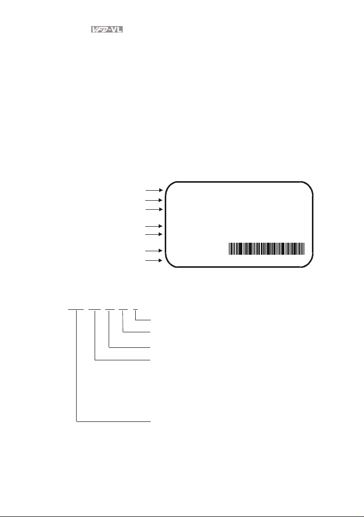
1.1.1 Nameplate Information
Example for 15HP/11kW 230V 3-Phase AC motor drive
AC Drive Model
Input Spec.
Output Spec.
Output Frequency Range
Software version
Bar Code
Serial Number
1.1.2 Model Explanation
11 0
VL
23
VFD A
MODEL
INPUT
OUTPUT
Freq. Range
Version:00.90
:VFD110VL23A
:3PH 180-264V 50/60Hz 43A
:3PH 0-230V 47A (LIFT DUTY)
41.1A(General)
11kW / 15HP
:0~120Hz
110VL23AT7260002
Ver sion Type
Mains Input Voltage
23: Three phase230V
43: Three phase460V
VFD-VL Series
Applicable motor capacity
055: 7 .5HP(5. 5kW)
075: 1 0 HP(7.5 kW)
110: 15 HP(11kW)
150: 2 0HP(15kW)
185: 25 HP(18.5kW)
220: 3 0 HP(22kW)
300: 4 0HP(30kW)
370: 5 0 HP(3 7kW)
450: 6 0 HP(4 5kW)
550: 7 5HP(55kW)
750: 100 H P(75k W)
Series Name ( ariable requency ri ve)VF D
1-2 Revision Nov. 2008, VLE1, SW V1.03
Page 12
Chapter 1 Introduction|
1.1.3 Series Number Explanation
267T110VL23A
Production number
Production week
Production year 2007
Production factory
230V 3-phase 15HP(11kW)
(T: Taoyuan, W: Wujian)
Model
If the nameplate information does not correspond to your purchase order or if there are
any problems, please contact your distributor.
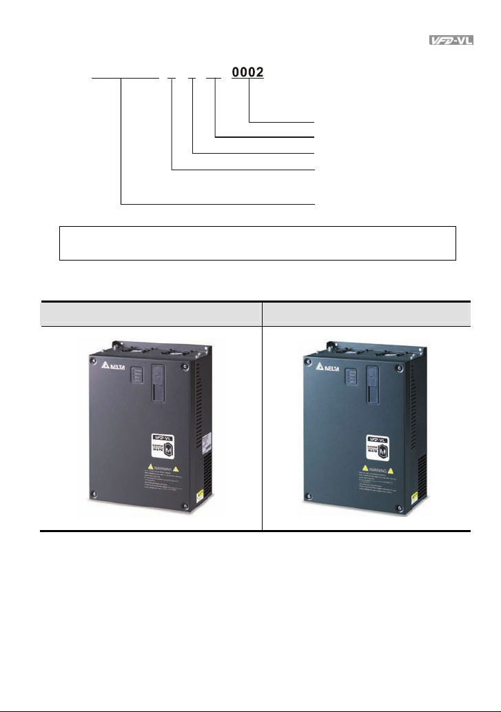
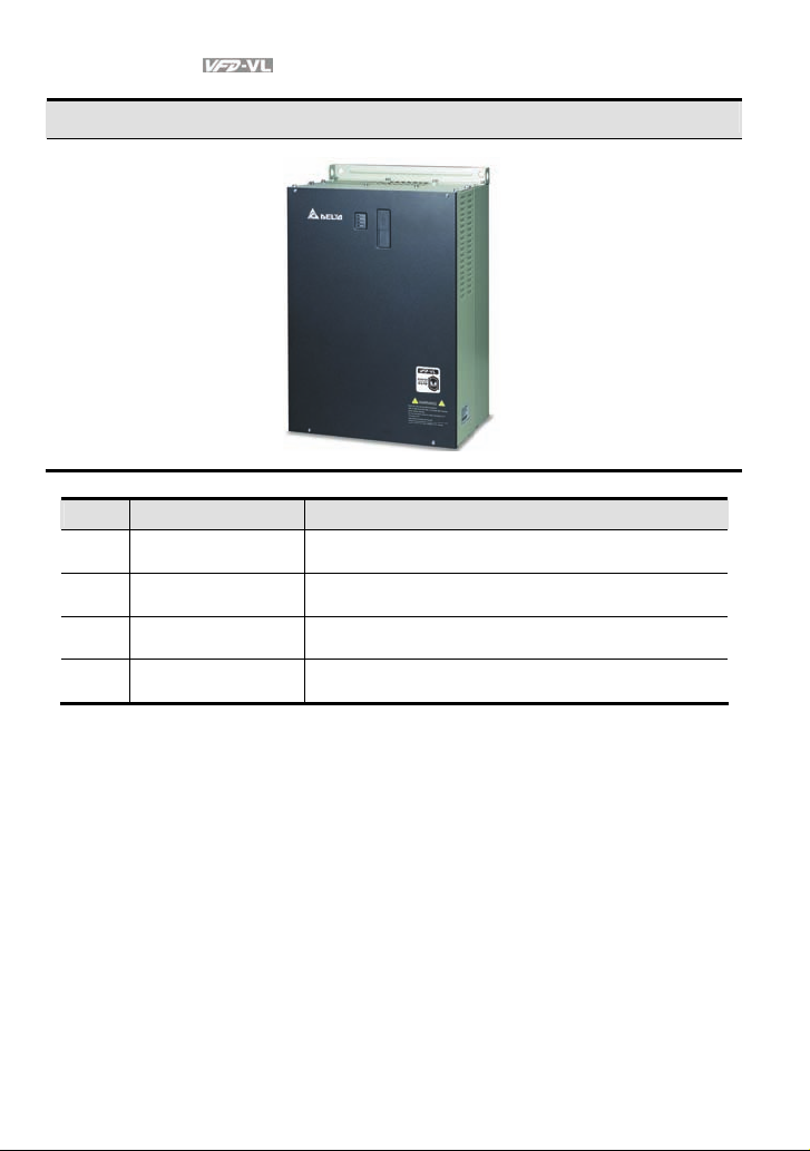
1.1.4 Drive Frames and Appearances
7.5-15HP/5.5-11kW(Frame C) 20-30HP/15-22kW(Frame D)
Revision Nov. 2008, VLE1, SW V1.03 1-3
Page 13
Chapter 1 Introduction|
40-100HP/30-75kW(Frame E)
Frame Power range Models
C 7.5-15HP (5.5-11kW)
D 20-30HP (15-22kW)
E (E1) 40-60hp (30-45kW) VFD300VL43A, VFD370VL43A, VFD450V43A
E (E2) 40-100hp (30-75kW)
Please refer to Chapter 1.3 for exact dimensions.
VFD055VL23A/43A, VFD075VL23A/43A,
VFD110VL23A/43A
VFD150VL23A/43A, VFD185VL23A/43A,
VFD220VL23A/43A
VFD300VL23A, VFD370VL23A, VFD550VL43A,
VFD750VL43A
1-4 Revision Nov. 2008, VLE1, SW V1.03
Page 14
Chapter 1 Introduction|
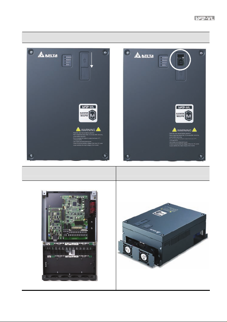
1.1.5 Drive Features
Communication Port
Internal structure Removable fan
Revision Nov. 2008, VLE1, SW V1.03 1-5
Page 15
Chapter 1 Introduction|
1.2 Preparation for Installation and Wiring
1.2.1 Ambient Conditions
Install the AC motor drive in an environment with the following conditions:
Air Temperature: -10 ~ +45°C (14 ~ 113°F)
Relative Humidity: <90%, no condensation allowed
Operation
Storage
Transportation
Pollution Degree 2: good for a factory type environment.
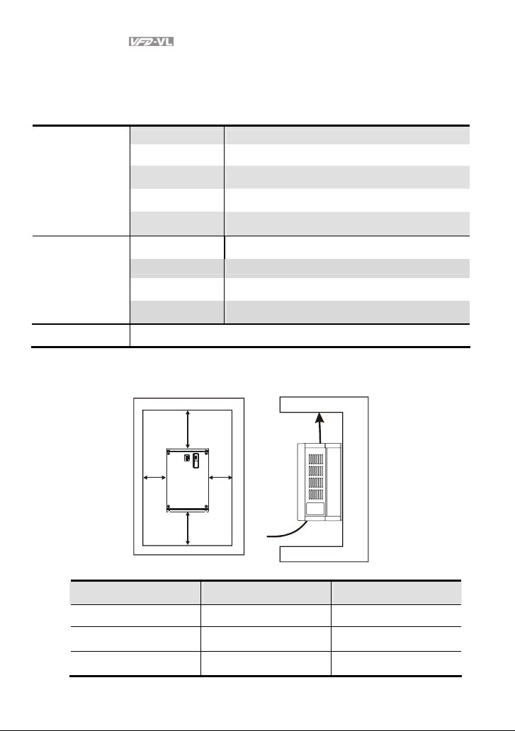
Minimum Mounting Clearances
Atmosphere
pressure:
Installation Site
Altitude:
Vibration:
Temperature: -20°C ~ +60°C (-4°F ~ 140°F)
Relative Humidity: <90%, no condensation allowed
Atmosphere
pressure:
Vibration:
86 ~ 106 kPa
<1000m
<20Hz: 9.80 m/s2 (1G) max
20 ~ 50Hz: 5.88 m/s2 (0.6G) max
86 ~ 106 kPa
<20Hz: 9.80 m/s2 (1G) max
20 ~ 50Hz: 5.88 m/s2 (0.6G) max
H
W
W
H
Air Flow
HP
7.5-20HP 75 (3) 175 (7)
25-75HP 75 (3) 200 (8)
100HP 75 (3) 250 (10)
1-6 Revision Nov. 2008, VLE1, SW V1.03
W
mm (inch)
H
mm (inch)
Page 16
Chapter 1 Introduction|
CAUTION!
1. Operating, storing or transporting the AC motor drive outside these conditions may cause
damage to the AC motor drive.
2. Failure to observe these precautions may void the warranty!
3. Mount the AC motor drive vertically on a flat vertical surface object by screws. Other directions
are not allowed.
4. The AC motor drive will generate heat during operation. Allow sufficient space around the unit
for heat dissipation.
5. The heat sink temperature may rise to 90°C when running. The material on which the AC motor
drive is mounted must be noncombustible and be able to withstand this high temperature.
6. When AC motor drive is installed in a confined space (e.g. cabinet), the surrounding
temperature must be within 10 ~ 40°C with good ventilation. DO NOT install the AC motor drive
in a space with bad ventilation.
7. Prevent fiber particles, scraps of paper, saw dust, metal particles, etc. from adhering to the
heatsink.
8. When installing multiple AC more drives in the same cabinet, they should be adjacent in a row
with enough space in-between. When installing one AC motor drive below another one, use a
metal separation between the AC motor drives to prevent mutual heating.
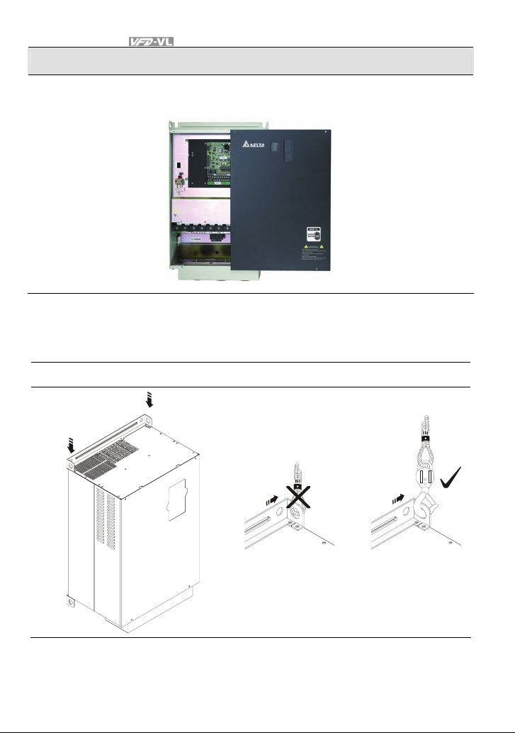
1.2.2 Remove Front Cover
7.5-15HP/5.5-11kW(frame C) & 20-30HP/15-22kW(frame D)
After removing the screws, please push the front cover to open it. For the open cover direction,
please refer to the following picture.
Revision Nov. 2008, VLE1, SW V1.03 1-7
Page 17
Chapter 1 Introduction|
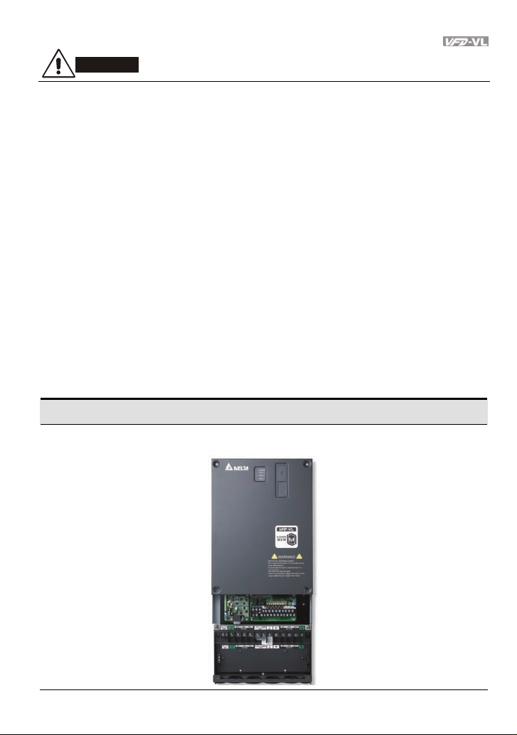
40-100HP/30-75kW (frame E)
After removing the screws, please push the front cover to open it. For the open cover direction,
please refer to the following picture.
1.2.3 Lifting
Please carry only fully assembled AC motor drives as shown in the following.
For 40-100HP (Frame E)
Step 1 Step 2
1-8 Revision Nov. 2008, VLE1, SW V1.03
Page 18
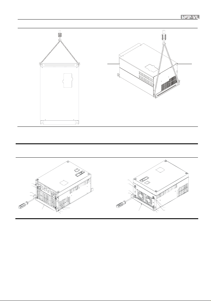
Chapter 1 Introduction|
Step 3 Step 4
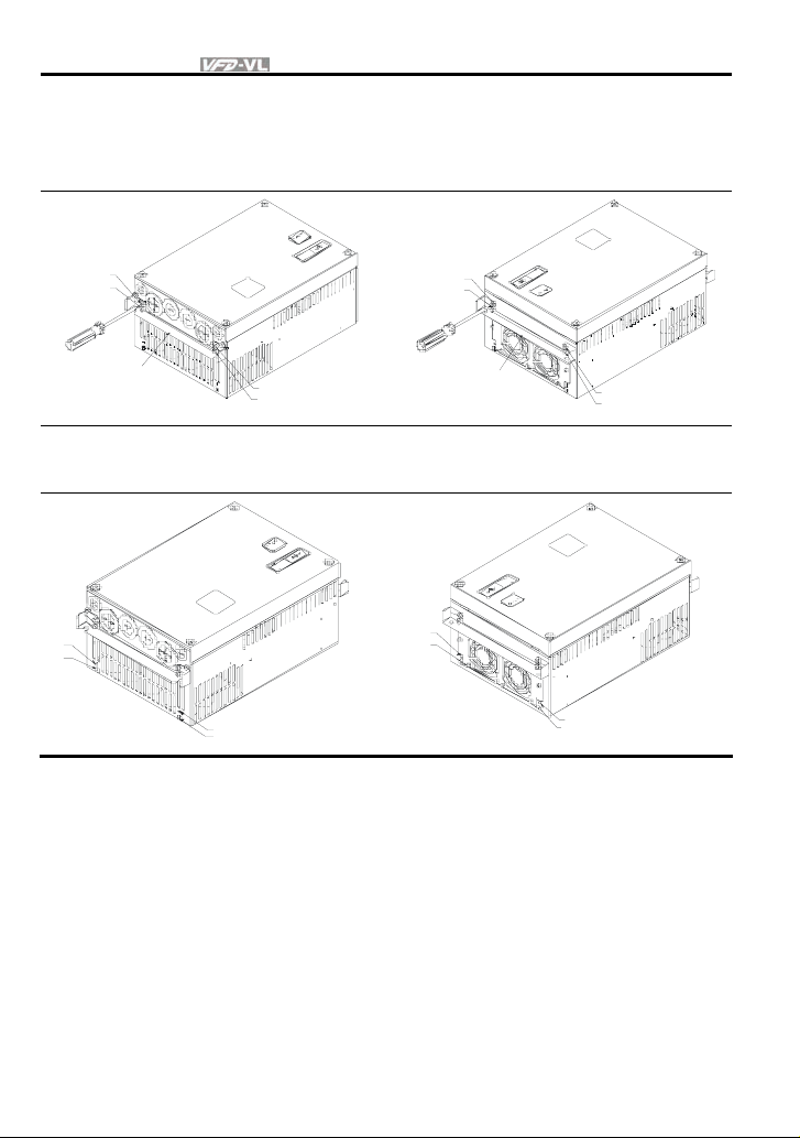
1.2.4 Flange Mounting
Step 1: Please take out the 16 screws (8 screws for each top and bottom side of the drive) and
remove the fixed plate 1 and fixed plate 2) as shown in the following figures.
1
2
5
6
fixed pla t e 1
3
4
7
8
1
2
5
6
fix ed pl at e 2
3
4
7
8
Revision Nov. 2008, VLE1, SW V1.03 1-9
Page 19
Chapter 1 Introduction|
Step 2: place the 8 screws back in to secure the fixed plate 1 and fixed plate 2 (as shown in the
following figures) with the following torque.
Frame C: 14-17kgf-cm [12.2-14.8in-lbf]
Frame D: 20-25kgf-cm [17.4-21.7in-lbf]
Frame E: 20-25kgf-cm [17.4-21.7in-lbf]
1
2
fixed plate 1
Step 3: Please notice that it doesn’t need to put those 8 screws shown in the following figures
back to the drive. Moreover, please make sure that these 2 different fixed plates are put in the
correct side as shown in the figures.
3
4
1
2
3
4
1-10 Revision Nov. 2008, VLE1, SW V1.03
1
2
fixed plate 2
5
6
3
4
7
8
Page 20
Chapter 1 Introduction|
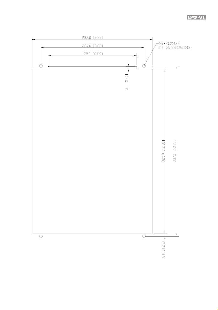
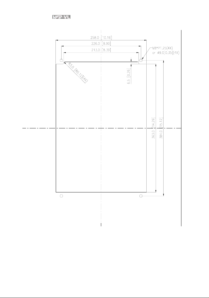
1.2.5 Cutout Dimensions
7.5-15HP/5.5-11kW (frame C)
Revision Nov. 2008, VLE1, SW V1.03 1-11
Page 21
Chapter 1 Introduction|
20-30HP/15-22kW (frame D)
1-12 Revision Nov. 2008, VLE1, SW V1.03
Page 22
Chapter 1 Introduction|
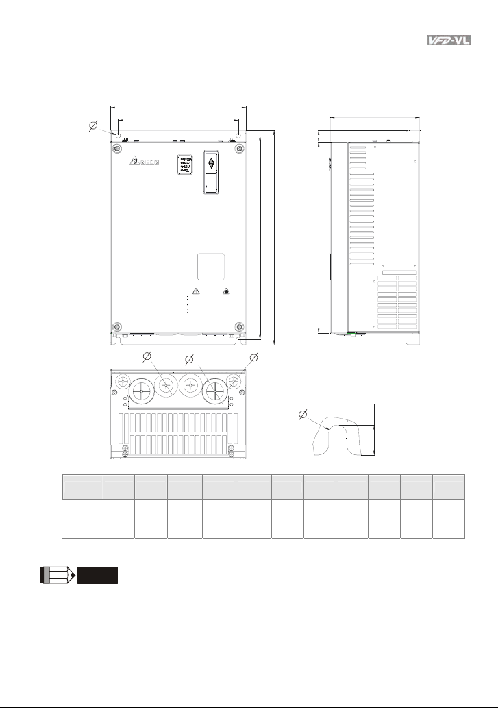
1.3 Dimensions
Frame C
2
W
W1
Read the user manual before operation.
Risk of electrical shock.Wait 10 minutes after removing
power before servicing.
Do not connect AC power to output terminals U/T1,
V/T2 and W/T3.
Use proper grounding techniques.
Check to be sure that the voltage of the main AC power
supply satisfies the rated voltage of the Inverter.
1
WARNING
D
H3
H
H1
3
H2
Frame W W1 H H1 H2 H3 D Ø Ø1 Ø2 Ø3
Unit: mm [inch]
34
136
235
204
350
337
320
C
[9.25]
[8.03]
[13.78]
[13.27]
[12.60]
[5.35]
6.5
[0.26]
[1.34]
22
[0.87]
NOTE
Frame C: VFD055VL23A/43A, VFD075VL23A/43A, VFD110VL23A/43A
Revision Nov. 2008, VLE1, SW V1.03 1-13
Page 23
Chapter 1 Introduction|
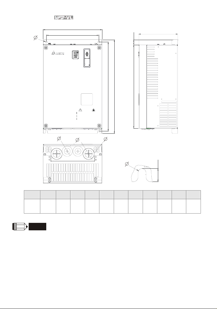
Frame D
W
W1
D
H3
H
H2
2
WARNING
Read the user manual before operation.
Risk of electrical shock.Wait 10 minutes after removing
power before servicing.
Do not connect AC power to output terminals U/T1,
V/T2 and W/T3.
Use proper grounding techniques.
Check to be sure that the voltage of the main AC power
supply satisfies the rated voltage of the Inverter.
1
H1
3
Unit: mm [inch]
Frame W W1 H H1 H2 H3 D Ø Ø1 Ø2 Ø3
255.0
226.0
403.8
384.0
360.0
21.9
168.0
8.5
D
[10.04]
[8.90]
[15.90]
[15.12]
[14.17]
[0.86]
[6.61]
[0.33]
44
[1.73]
NOTE
Frame D: VFD150VL23A/43A, VFD185VL23A/43A, VFD220VL23A/43A
34
[1.34]
22
[0.87]
1-14 Revision Nov. 2008, VLE1, SW V1.03
Page 24
Chapter 1 Introduction|
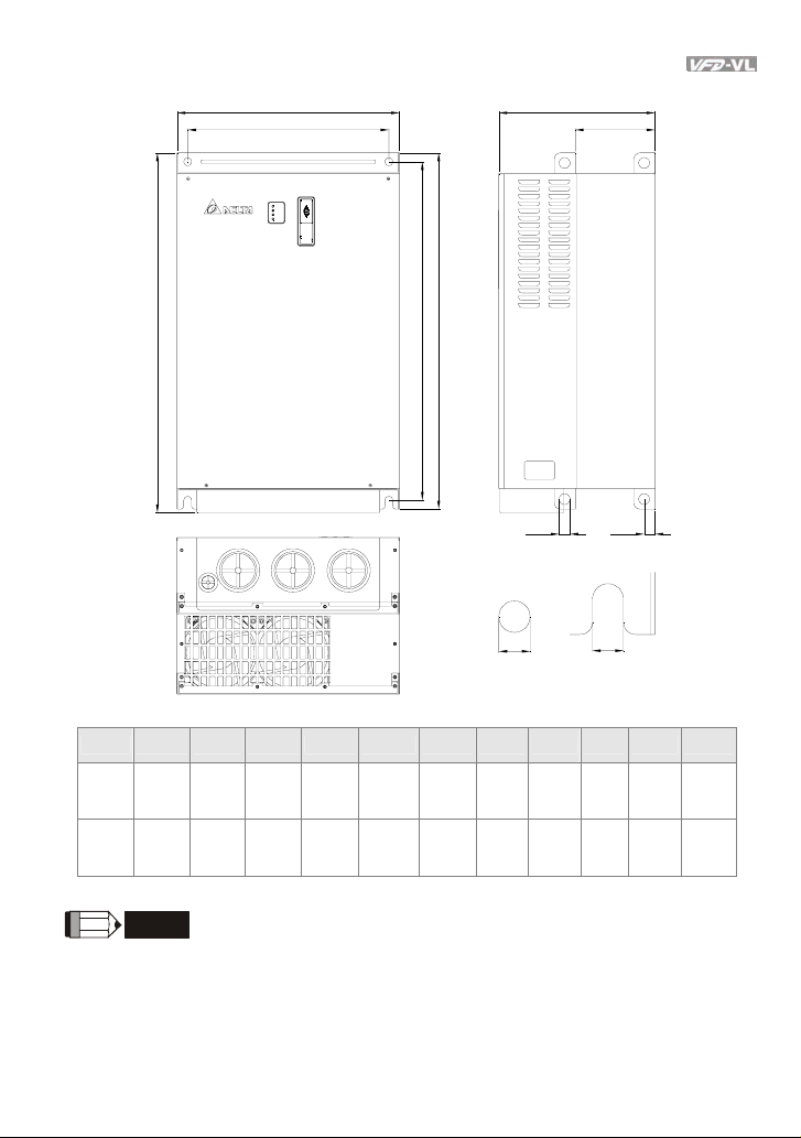
Frame E
W D
W1
D1
H
H1
H2
S3
S1
D2
S2
Unit: mm [inch]
Frame W W1 H H1 H2 D D1 D2 S1 S2 S3
370.0
E1
E2
[14.57]
370.0
[14.57]
335.0
[13.19]
335.0
[13.19]
-
595.0
[23.43]
589.0
[23.19]
589.0
[23.19]
560.0
[22.05]
560.0
[22.05]
260.0
[10.24]
260.0
[10.24]
132.5
[5.22]
132.5
[5.22]
18.0
[0.71]
18.0
[0.71]
13.0
[0.51]
13.0
[0.51]
13.0
[0.51]
13.0
[0.51]
NOTE
Frame E1: VFD300VL43A, VFD370VL43A, VFD450VL43A
Frame E2: VFD300VL23A, VFD370VL23A, VFD550VL43A, VFD750VL43A
18.0
[0.71]
18.0
[0.71]
Revision Nov. 2008, VLE1, SW V1.03 1-15
Page 25

Chapter 1 Introduction|
This page intentionally left blank
1-16 Revision Nov. 2008, VLE1, SW V1.03
Page 26

Chapter 2 Installation and Wiring
After removing the front cover (see chapter 1.2.2 for details), check if the power and control
terminals are clear. Be sure to observe the following precautions when wiring.
CAUTION!
1. Make sure that power is only applied to the R/L1, S/L2, T/L3 terminals. Failure to comply may
result in damage to the equipment. The voltage and current should lie within the range as
indicated on the nameplate.
2. Check the following items after finishing the wiring:
A. Are all connections correct?
B. No loose wires?
C. No short-circuits between terminals or to ground?
DANGER!
1. A charge may still remain in the DC bus capacitors with hazardous voltages even if the power
has been turned off. To prevent personal injury, please ensure that the power is turned off and
wait ten minutes for the capacitors to discharge to safe voltage levels before opening the AC
motor drive.
2. All the units must be grounded directly to a common ground terminal to prevent lightning strike
or electric shock.
3. Only qualified personnel familiar with AC motor drives is allowed to perform installation, wiring
and commissioning.
4. Make sure that the power is off before doing any wiring to prevent electric shock.
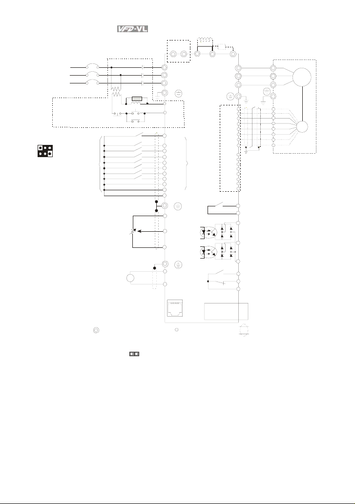
2.1 Wiring
Users must connect wires according to the circuit diagrams on the following pages. Do not plug a
modem or telephone line to the RS-485 communication port or permanent damage may result.
Pins 1 & 2 are the power supply for the optional copy keypad only and should not be used for RS485 communication.
Revision Nov. 2008, VLE1, SW V1.03 2-1
Page 27
Chapter 2 Installation and Wiring|
r
Fuse/NFB(No F use Breaker)
NFB
R
S
T
Recommended Circuit
when power s uppl y
is turned O FF by a
fault output
Factory setting:
SINK Mode
*
Please refer to the
following figure for wiring
of SINK mode and SOURCE
mode.
*RS-485
To commun icate to PC, it needs
to use conv erter (VFD -USB0 1 or
IFD8 500).
Forwar d/STOP
Rever se/STOP
Multi-step 1
Multi-step 2
Multi-st ep 3
Factory
Multi-st ep 4
setting
No fun ction
No function
No function
No fun ction
Digital Signal Common
Ma in circ uit ( pow er) te rmina ls
Terminal EPS is emergency power input terminal, refer to the following figure for details.
*
For P G car d, refer to Appe ndix B for d etails .
*
(*1) When JP1
EPS
*
MC
+
R(L1)
S(L2)
T(L3 )
E
RB
RC
OFF
SA
MC
ON
MC
FWD
REV
MI1
MI2
MI3
MI4
MI5
MI6
(*1)
MI7
MI8(*1)
COM
E
+10V
Power supply
+10V 20mA
AUI1/AUI2
Master
Frequency
-10 to 10V
-10V
Power supply
-10V 20mA
E
A
4~20mA
ACI
ACM
1:+EV
1 2 3 4 5 6
2:GND
3:SG4:SG+
5:NC
6:NC
on t he co ntrol boar d is in sert ed, M I8 is disa bled .
Br ake re si sto
(optional)
-
+1 +2/B1
U(T1)
V(T2)
W(T3)
E
multifunction
ter minals
EMVL-IOD01
extension c ard
(optional)
Control circuit terminals
Brake res istor/Unit( optional)
Re fer t o App endi x B fo r th e us e of
special brake resistor/unit
B2
U
V
W
PG Card (optional)
PG Card (optional)
EMVL- PGABL
EMVL- PGABO
EMVL- PGH01
Multi-function contact output 2 (Relay)
240VAC 3A
MRA
120VAC 3A
24VDC 3A
MRC
factor y setting :
indicates that it is running
MO1
Multi-function contact output 3
(photocoupler)
48VDC 50mA
MO2
Multi -functi on contact output 4
(photocoupler)
MCM
Multi -functi on
Ph otoc oupl er Outp ut
RA
RB
RC
increment al encoder
Multi-function contact
output 1 (Relay)
240VAC 3A
120VAC 3A
24VDC 3A
factory se tting:
fault indication
Shielded leads & C able
Motor
IM/PM
PG
Line driver
2-2 Revision Nov. 2008, VLE1, SW V1.03
Page 28
Chapter 2 Installation and Wiring|
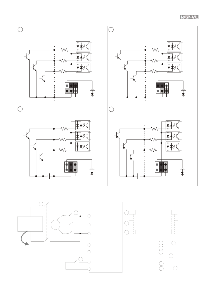
m
.
Figure 2 Wiring/Terminals setting for SINK(NPN) mode and SOURCE(PNP) mode
1
Sink (NPN) mode
2
Source (PNP) mode
used with internal power (+24Vdc) used with internal power (+24Vdc)
MI1
MI2
~
MI8
COM
3
Sink (NPN) mode
used with external power
MI1
MI2
~
MI8
+
COM
+24V
+24V
Source (PNP) mode
4
used with external power
MI1
MI2
~
MI8
COM
MI1
MI2
~
MI8
+
COM
Figure 3 Apply to 1-phase UPS power supply syste
1
Main power
1-phase UPS
or battery
Specifications for
1-phase UPS and battery
250VDC (for 230V series)
500VDC (for 460V series)
To input emergency power
3
~
AC motor drive
2
R/L1
S/L2
T/L3
EPS/+
EPS/-
3
MI1~8
COM
Timing diagram of M.C.
(magnetic contact or)
1
2
3
Before i nputting emergency power,
magnetic contactor and are ON and
magnetic contactor should be OFF.
Magnetic contactor should be ON
after magnetic c ontactor is ON.
Before r emoving battery and turn
magnetic contactor to be ON,
magnetic contactor and should be
OFF
3
1
2
3
1
2
1
Revision Nov. 2008, VLE1, SW V1.03 2-3
+24V
+24V
3
Page 29
Chapter 2 Installation and Wiring|
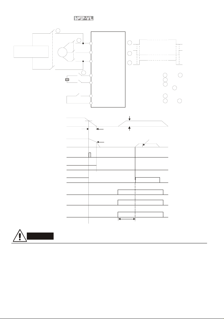
c
.
Figure 4 Apply to two batteries with main battery voltage is lower than 2 80Vd
Timing diagram of M.C.
(magnetic contact or)
1
2
3
Before inputting emergency power,
magnetic contactor and are ON and
magnetic contactor should be OFF.
Magnetic contactor should be ON
after magnetic contactor is ON.
Before removing battery and turn
magnetic contactor to be O N,
magnetic contactor and should be
OFF.
1
2
3
1
2
1 3
3
48Vdc (230V Se ries)
96Vdc (460V Se ries)
1-phase UP S or battery
Specifications for
1-phase UP S and battery
250VDC (for 230V series)
500VDC (for 460V series)
To input emergency power
1
Main
power
3
~
2
3
AC motor drive
R/L1
S/L2
T/L3
EPS/+
EPS/-
MI1~8
COM
DC voltage
motor speed
error output
electromagn etic
valve
operat ion
command
MI-COM=43
electromagn etic
valve
EPS detection
MO-COM=9
low volt age level
free run
mechan ical br ake
OFF
drive ready
batt ery voltage
about 1 min.
ON
ON
ON
about 2 sec
default EPS operati on
frequ ency
CAUTION!
1. The wiring of main circuit and control circuit should be separated to prevent erroneous actions.
2. Please use shield wire for the control wiring and not to expose the peeled-off net in front of the
terminal.
3. Please use the shield wire or tube for the power wiring and ground the two ends of the shield
wire or tube.
4. Damaged insulation of wiring may cause personal injury or damage to circuits/equipment if it
comes in contact with high voltage.
2-4 Revision Nov. 2008, VLE1, SW V1.03
Page 30
Chapter 2 Installation and Wiring|
5. The AC motor drive, motor and wiring may cause interference. To prevent the equipment
damage, please take care of the erroneous actions of the surrounding sensors and the
equipment.
6. When the AC drive output terminals U/T1, V/T2, and W/T3 are connected to the motor terminals
U/T1, V/T2, and W/T3, respectively. To permanently reverse the direction of motor rotation,
switch over any of the two motor leads.
7. With long motor cables, high capacitive switching current peaks can cause over-current, high
leakage current or lower current readout accuracy. For longer motor cables use an AC output
reactor.
8. The AC motor drive, electric welding machine and the greater horsepower motor should be
grounded separately.
9. Use ground leads that comply with local regulations and keep them as short as possible.
10. No brake resistor is built in the VFD-VL series, it can install brake resistor for those occasions
that use higher load inertia or frequent start/stop. Refer to Appendix B for details.
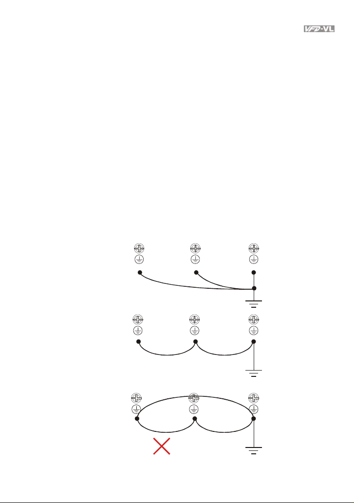
11. Multiple VFD-VL units can be installed in one location. All the units should be grounded directly
to a common ground terminal, as shown in the figure below. Ensure there are no ground
loops.
grouning
terminals
grouning
terminals
Excellent
Good
grouni ng
terminals
Not allowed
Revision Nov. 2008, VLE1, SW V1.03 2-5
Page 31

Chapter 2 Installation and Wiring|
y
p
2.2 External Wiring
Power Suppl
EMI Filter
R/L1 S/L2
U/T1 V/T2
T/L3
W/T3
FUSE/NFB
Magnetic
cont actor
Input AC
Line React or
Zero-phase
Reactor
+/B1
B2
-
Zero-phase
Reactor
Outpu t AC
Line React or
Brake resister
Items Explanations
Power
supply
Please follow the specific power
supply requirements shown in
Appendix A.
There may be an inrush current
Fuse/NFB
(Optional)
during power up. Please check the
chart of Appendix B and select the
correct fuse with rated current. Use of
an NFB is optional.
Magnetic
contactor
(Optional)
Please do not use a Magnetic
contactor as the I/O switch of the AC
motor drive, as it will reduce the
operating life cycle of the AC drive.
Used to improve the input power
factor, to reduce harmonics and
provide protection from AC line
Input AC
Line Reactor
(Optional)
disturbances.
spikes, short interruptions, etc.). AC
line reactor should be installed when
the power supply capacity is 500kVA
(surges, switching
or more and exceeds 6 times the
inverter capacity, or the mains wiring
distance
10m.
≤
Zero phase reactors are used to
Zero-phase
Reactor
(Ferrite Core
Common
Choke)
(Optional)
reduce radio noise especially when
audio equipment is installed near the
inverter. Effective for noise reduction
on both the input and output sides.
Attenuation quality is good for a wide
range from AM band to 10MHz.
Appendix B specifies the zero phase
reactor. (RF220X00A)
EMI filter
(Optional)
Brake
Resistor
(Optional)
To reduce electromagnetic
interference, please refer to Appendix
B for more details.
Used to reduce the deceleration time
of the motor. Please refer to the chart
in Appendix B for specific Brake
Resistors.
Output AC
Motor
2-6 Revision Nov. 2008, VLE1, SW V1.03
Line Reactor
(Optional)
Motor surge voltage amplitude
depends on motor cable length. For
applications with long motor cable
(>20m), it is necessary to install a
reactor at the inverter out
ut side.
Page 32

2.3 Main Circuit
2.3.1 Main Circuit Connection
Non-fuse breaker
( NF B )
R
S
T
Terminal Symbol Explanation of Terminal Function
EPS (+, -) For emergency power or backup power supply
R/L1, S/L2, T/L3 AC line input terminals
U/T1, V/T2, W/T3
+1, +2/B1
+2/B1, B2 Connections for Brake Resistor (optional)
Chapter 2 Installation and Wiring|
Br ake res ist or
(Optional)
EPS
*
MC
+
R(L1)
S(L2)
T(L3)
E
-
+1 +2/B1
B2
U(T1)
V(T2)
W(T3)
E
AC drive output terminals for connecting 3-phase
induction motor
Connections for DC Choke (optional). Please remove
jumper when installation. (It is built in DC choke for
models 22kW and above)
Earth connection, please comply with local regulations.
Motor
IM
3~
Revision Nov. 2008, VLE1, SW V1.03 2-7
Page 33

Chapter 2 Installation and Wiring|
Mains power terminals (R/L1, S/L2, T/L3)
Connect these terminals (R/L1, S/L2, T/L3) via a non-fuse breaker or earth leakage
breaker to 3-phase AC power (some models to 1-phase AC power) for circuit protection.
It is unnecessary to consider phase-sequence.
It is recommended to add a magnetic contactor (MC) in the power input wiring to cut off
power quickly and reduce malfunction when activating the protection function of AC motor
drives. Both ends of the MC should have an R-C surge absorber.
Please make sure to fasten the screw of the main circuit terminals to prevent sparks
which is made by the loose screws due to vibration.
Please use voltage and current within the regulation shown in Appendix A.
When using a general GFCI (Ground Fault Circuit Interrupter), select a current sensor
with sensitivity of 200mA or above, and not less than 0.1-second operation time to avoid
nuisance tripping. For the specific GFCI of the AC motor drive, please select a current
sensor with sensitivity of 30mA or above.
Do NOT run/stop AC motor drives by turning the power ON/OFF. Run/stop AC motor
drives by RUN/STOP command via control terminals or keypad. If you still need to
run/stop AC drives by turning power ON/OFF, it is recommended to do so only ONCE per
hour.
Do NOT connect 3-phase models to a 1-phase power source.
Output terminals for main circuit (U, V, W)
When it needs to install the filter at the output side of terminals U/T1, V/T2, W/T3 on the
AC motor drive. Please use inductance filter. Do not use phase-compensation capacitors
or L-C (Inductance-Capacitance) or R-C (Resistance-Capacitance), unless approved by
Delta.
DO NOT connect phase-compensation capacitors or surge absorbers at the output
terminals of AC motor drives.
Use well-insulated motor, suitable for inverter operation.
Terminals [+1, +2] for connecting DC reactor, terminals [+1, +2/B1] for connecting brake
resistor
DC reactor
Jumper
+1
To improve power factor and reduce harmonics connect a DC reactor between terminals
[+1, +2/B1]. Please remove the jumper before connecting the DC reactor.
2-8 Revision Nov. 2008, VLE1, SW V1.03
Page 34

Chapter 2 Installation and Wiring|
Models above 22kW don’t have a built-in brake chopper. Please connect an external
optional brake resistor.
When not used, please leave the terminals [+2/B1, -] open.
Short-circuiting [B2] or [-] to [+2/B1] can damage the AC motor drive.
2.3.2 Main Circuit Terminals
Frame C
/~ U/T1
+/~
T/L3
R/L1 S/L2
EPS
POWER MOTOR
+/~ R/L1 S/L2 T/L3
/~ U/T1
EPS
POWER MOTOR
+2/B1
+1
B2
DC-
DC+
+2/B1
+1
B2
DC-
DC+
Main circuit terminals
R/L1, S/L2, T/L3, U/T1, V/T2, W/T3,
Models Wire Torque Wire Type
VFD055VL23A
VFD110VL43A
VFD055VL43A
VFD075VL43A
V/T2 W/T3
W/T3
V/T2
VFD075VL23A
VFD110VL23A
10-6 AWG.
(5.3-13.3mm
12-6 AWG.
(3.3-13.3mm
8-6 AWG.
(8.4-13.3mm
6 AWG.
(13.3mm
2
)
2
)
2
)
2
)
, +1, +2/B1, -, B2
30kgf-cm
(26in-lbf)
Stranded
copper only,
o
75
C
Frame D
Main circuit terminals
R/L1, S/L2, T/L3, U/T1, V/T2, W/T3,
, +1, +2, -
Models Wire Torque Wire Type
VFD150VL43A
VFD185VL43A
VFD150VL23A
VFD185VL23A
VFD220VL43A
VFD220VL23A
8-2 AWG.
(8.4-33.6mm
4-2 AWG.
(21.1-33.6mm
3-2 AWG.
(26.7-33.6mm
6-2 AWG
(13.3-33.6mm2)
3-2 AWG
(26.7-33.6mm2)
2
)
2
)
2
)
(43.4 lbf-in)
50Kgf-cm
Stranded
copper only,
o
C
75
Revision Nov. 2008, VLE1, SW V1.03 2-9
Page 35

Chapter 2 Installation and Wiring|
Frame E
2.4 Control Terminals
Main circuit terminals
R/L1, S/L2, T/L3, U/T1, V/T2, W/T3,
, +1, +2, -
Models Wire Torque Wire Type
VFD300VL43A
VFD370VL43A
57kgf-cm
(49in-lbf)
VFD450VL43A
VFD300VL23A
VFD370VL23A
VFD550VL43A
4-2 AWG.
(21.2-33.6mm2)
200kgf-cm
(173in-lbf)
VFD750VL43A
Stranded
copper only,
o
75
C
1
Sink /NPN Mode
2
So urce Mode
used with internal power (+24Vdc)
MI1
MI2
MI8
~
+2 4V
COM
MI1
MI2
MI8
~
+2 4V
COM
The Position of External Terminals
+E24VDCM
Sink/Sourc e
RB
MRCRAMRA
RC
2-10 Revision Nov. 2008, VLE1, SW V1.03
MO1
MCM
MO2
FWD
REV
MI1
MI2
MI3
MI4
MI5
MI6
MI7
COM ACMAUI1
+10V
MI8
AUI2
-10V
mode switch
ACI
Page 36

Terminal symbols and functions
Terminal
Symbol
Terminal Function
FWD Forward-Stop Command
REV Reverse-Stop Command
MI1 Multi-function Input 1
MI2 Multi-function Input 2
MI3 Multi-function Input 3
MI4 Multi-function Input 4
MI5 Multi-function Input 5
MI6 Multi-function Input 6
MI7 Multi-function Input 7
MI8 Multi-function Input 8
COM Digital Signal Common
Chapter 2 Installation and Wiring|
Factory Settings (SINK)
ON: Connect to DCM
ON: RUN in FWD direction
OFF: Stop acc. to Stop Method
ON: RUN in REV direction
OFF: Stop acc. to Stop Method
Refer to Pr.02-01 to Pr.02-08 for programming
the Multi-function Inputs.
ON: input voltage is 24Vdc (Max. 30Vdc), input
impedance is 3.75k
OFF: leakage current tolerance is 10A.
MI8: when JP1 is inserted, this function is
disabled.
Common for digital inputs and used for SINK
mode
+E24V
Digital Signal Common
(Source)
DCM Digital Signal Common (Sink)
Multi-function Relay Output 1
RA
(N.O.) a
Multi-function Relay Output 1
RB
(N.C.) b
RC Multi-function Relay Common
MRA
Multi-function Relay Output 2
(N.O.) a
MRC Multi-function Relay Common
+10V
-10V
MCM
Revision Nov. 2008, VLE1, SW V1.03 2-11
Potentiometer Power Supply -10~+10VDC 20mA (variable resistor 3-5kohm)
Multi-function Output
Common (Photocoupler)
+24V 80mA
Common for digital inputs and used for SINK
mode
Resistive Load:
5A(N.O.)/3A(N.C.) 240VAC
5A(N.O.)/3A(N.C.) 24VDC
Inductive Load:
1.5A(N.O.)/0.5A(N.C.) 240VAC
1.5A(N.O.)/0.5A(N.C.) 24VDC
To output monitor signal, including in operation,
frequency arrival, overload and etc.
Refer to Pr.02-11~02-12 for programming
Max. 48VDC 50mA
Page 37

Chapter 2 Installation and Wiring|
A
Terminal
Symbol
MO1
MO2
Terminal Function
Multi-function Output 1
(Photocoupler)
Multi-function Output 2
(Photocoupler)
Factory Settings (SINK)
ON: Connect to DCM
The AC motor drive output every monitor signal,
such as operational, frequency attained,
overload, etc. by open collector transistor. Refer
to Pr.03.01 multi-function output terminals for
details.
Max: 48Vd c/50m
MO1
~
MO2
internal circuit
Analog current Input
ACI circuit
ACI
Impedance: 250
Resolution: 12 bits
Range: 4 ~ 20mA/0~10V =
ACI
0 ~ Max. Output Frequency
(Pr.01-00)
Set-up: Pr.03-00 ~ Pr.03-02
ACM
internal circuit
Auxiliary analog voltage input
Impedance: 2m
Resolution: 12 bits
Range: -10 ~ +10VDC =
0 ~ Max. Output Frequency
AUI1/
AUI2
+10V
|
-10V
AUI
AUI c ircu it
(Pr.01-00)
Set-up: Pr.03-00 ~ Pr.03-02
Common for ACI, AUI1, AUI2
ACM
ACM
internal circuit
Analog control signal
(common)
*Control signal wiring size: 18 AWG (0.75 mm2) with shielded wire.
Analog input terminals (ACI, AUI1, AUI2, ACM)
MCM
2-12 Revision Nov. 2008, VLE1, SW V1.03
Page 38

Chapter 2 Installation and Wiring|
A
Analog input signals are easily affected by external noise. Use shielded wiring and keep it
as short as possible (<20m) with proper grounding. If the noise is inductive, connecting
the shield to terminal ACM can bring improvement.
If the analog input signals are affected by noise from the AC motor drive, please connect
a capacitor and ferrite core as indicated in the following diagrams:
C
ferrite core
CI/AUI1/AUI2
ACM
wind each wires 3 times or more around the core
Digital inputs (FWD, REV, MI1~MI8, COM)
When using contacts or switches to control the digital inputs, please use high quality
components to avoid contact bounce.
Digital outputs (MO1, MO2, MCM)
Make sure to connect the digital outputs to the right polarity, see wiring diagrams.
When connecting a relay to the digital outputs, connect a surge absorber or fly-back diode
across the coil and check the polarity.
The specification for the control terminals
The Position of External Terminals
Sink/Source
RB
RC
MRCRAMRA
MO1
MCM
MO2
FWD
REV
MI1
MI2
MI3
MI4
MI5
MI7
MI6
mode switch
COM ACMAUI1
+10V
AUI2
MI8
-10V
ACI
Frame Torque Wire
C, D, E
Terminal: 0V/24V 1.6 kgf-com(1.4 in-lbf) 30-16 AWG (0.051-1.3mm
8 kgf-cm (6.9 in-lbf) 22-14 AWG (0.3-2.1mm2)
+E24VDCM
2
)
Revision Nov. 2008, VLE1, SW V1.03 2-13
Page 39

Chapter 2 Installation and Wiring|
NOTE
Frame C: VFD055VL23A/43A, VFD075VL23A/43A, VFD110VL23A/43A
Frame D: VFD150VL23A/43A, VFD185VL23A/43A, VFD220VL23A/43A
Frame E: VFD300VL23A/43A, VFD370VL23A/43A, VFD450VL43A, VFD550VL43A, VFD750VL43A
2-14 Revision Nov. 2008, VLE1, SW V1.03
Page 40

Chapter 3 Operation and Start Up
Make sure that the wiring is correct. In particular, check that the
output terminals U/T1, V/T2, W/T3 are NOT connected to power
3.1 Operation Method
The factory setting for operation method is set to control terminal. But it is just one of the operation
methods. The operation method can be via communication, control terminals settings or optional
digital keypad KPVL-CC01. Please choose a suitable method depending on application and
operation rule. The operation is usually used as shown in the following table.
and that the drive is well grounded.
Verify that no other equipment is connected to the AC motor
Do NOT operate the AC motor drive with humid hands.
Verify that there are no short-circuits between terminals and from
terminals to ground or mains power.
Check for loose terminals, connectors or screws.
Make sure that the front cover is well installed before applying
power.
Please do NOT touch output terminals U, V, W when power is still
applied to L1/R, L2/S, L3/T even when the AC motor drive has
stopped. The DC-link capacitors may still be charged to hazardous
voltage levels, even if the power has been turned off.
Revision Nov. 2008, VLE1, SW V1.03 3-1
Page 41

Chapter 3 Operation and Start Up|
Operation Method Frequency Source
Operate from
communication
Please refer to the communication address 2000H and 2119H settings
in the communication address definition.
F act or y set ting :
SINK Mode
*
Factory
setting
Control Terminals-
Operate from
external signal
NOTE
* Don't apply the mains v oltage directly
to above terminals.
(*1) When JP1
on t he c ontr ol bo ar d is in ser ted , MI8 i s di sab led.
Forwar d/STOP
Rever se/STOP
Multi-st ep 1
Multi-st ep 2
Multi-step 3
Multi -step 4
No fun ction
No function
No function
(*1)
No fun ction
Digit al Signal C ommon
A
4~20mA
Operation
Command Source
FW D
REV
MI1
MI2
multif unction
MI3
te rmin als
MI4
MI5
MI6
MI7
(*1)
MI8
COM
E
+10V
AUI1/AUI2
Ma st er Fre que ncy
-10 to 10V
-10V
Power supply-10V 20mA
E
ACI
ACM
KPVL-CC01
keypad
(Optional)
RUN,
UP/DOWN key
STOP/RESET
key
3-2 Revision Nov. 2008, VLE1, SW V1.03
Page 42

Chapter 3 Operation and Start Up|
3.2 Trial Run
The factory setting of operation source is from external terminals.
1. Please connect a switch for both external terminals FWD-COM and REV-COM.
2. Please connect a potentiometer among AUI1/AUI2, +10V, -10V and ACM or apply power –10
~+10Vdc to AUI1/AUI2-ACM.
3. Setting the potentiometer or -10~+10Vdc power to less than 1V.
4. Make sure that all external terminal wirings are finished before applying power. After applying
power, verify that LED “READY” is ON.
5. Setting FWD-COM=ON for forward running. And if you want to change to reverse running
direction, you should set REV-COM=ON. And if you want to decelerate to stop, please set
FWD/REV-COM=OFF.
6. Check following items:
Check if the motor direction of rotation is correct.
Check if the motor runs steadily without abnormal noise and vibration.
Check if acceleration and deceleration are smooth.
If the results of trial run are normal, please start the formal run.
Revision Nov. 2008, VLE1, SW V1.03 3-3
Page 43

Chapter 3 Operation and Start Up|
3.3 Auto-tuning Operations
3.3.1 Flow Chart
St ep 1 B asi c par ame ter s et ting s
Setting all parameters
to factory setting
Pr.00-02
Source of th e Ma ster
Frequency Command
Pr.00-14
Source of the
Ope rat io n Comm an d
Pr.00-15
MI/MO terminals Settings
Pr.02-01~0 2-08
Pr.02-13~0 2-22
Step 3 Encoder settings
Step 2 Motor tuning
Motor ty pe
[PM/IM]
IM
Set tin g t he r elat ed
informat ion of IM motor
P r. 01 -00 ~0 1-0 2
P r.05-01~05-04
IM Motor Auto-tuning
Pr.05-00
Selection of speed
feedback card
EMVL-PGABL
EMVL-PGABO
EMVL-PGH01
EMVL-PGS01
Encoder se lecti on
Pr.10-00
PM
Control Mode Selection
P r.00-09
Set tin g t he r elat ed
informat ion of P M motor
P r.01 -00~ 01- 02
P r.08 -01~ 08- 04
PM Mo tor Auto -t unin g
Pr.08-00
De tec tio n of the HO ME
position of Encoder
1. us ing digi ta l keyp ad
2. using external terminals
Set tin g En co der in fo rmat ion
Pr.10-00~10-02
Step 4 Multi-step speed settings
Set tin g s pee d, acc el /dec el. t ime and S cu rve
Pr.04-00~04-15
Pr.01-12~01-19
Pr.01-24~01-30
Step 5 Trial run
Step 6 Elevator tuning
Smooth test
Pr.11-00 bit0=1
Pr.11-05~11-08
3-4 Revision Nov. 2008, VLE1, SW V1.03
Trial run
1. tuning as sta rt-up
2. tu ning as stop
Page 44

Chapter 3 Operation and Start Up|
3.3.2 Explanations for the Auto-tuning Steps
3.3.2.1 Step 1
Basic parameters settings
Make sure that Pr.00-00 (identity code of the AC motor drive) corresponds with the
nameplate indicated on the AC motor drive.
Make sure that all parameters are reset to factory setting (Pr.00-02 is set to 9 or 10).
Pr.00-02
Parameter Reset
Source of the Master Frequency Command: users can set by themselves (Pr.00-14)
Pr.00-14
Source of the
Master Frequency
Command
Source of the Operation Command: users can set by themselves (Pr.00-15)
Pr.00-15
Source of the
Operation
Command
MI/MO external terminals settings:
Refer to Pr.02-01~02-08 for setting the external input terminals MI1~MI8.
NOTE: The factory setting of Pr.02-08 is 40 (Enable drive function). Please disable this
function if you don’t need to use this function.
Settings of Pr.0201~02-08
0: No function
1: Read only
8: Keypad lock
9: All parameters are reset to factory settings (50Hz,
220V/380V)
10: All parameters are reset to factory settings (60Hz,
220V/440V)
1: RS-485 serial communication or digital keypad
(KPVL-CC01)
2: External analog input (Pr. 03-00)
3: Digital terminals input
1: External terminals
2: RS-485 serial communication or digital keypad
(KPVL-CC01)
0: no function
1: multi-step speed command 1
2: multi-step speed command 2
3: multi-step speed command 3
4: multi-step speed command 4
5: Reset
6: JOG command
7: acceleration/deceleration speed inhibit
8: the 1st, 2nd acceleration/deceleration time selection
9: the 3rd, 4th acceleration/deceleration time selection
10: EF input (07-28)
11: Reserved
12: Stop output
13: Disable auto accel./decel. function
Revision Nov. 2008, VLE1, SW V1.03 3-5
Page 45

Chapter 3 Operation and Start Up|
Settings of Pr.0201~02-08
14: Reserved
15: operation speed command form AUI1
16: operation speed command form ACI
17: operation speed command form AUI2
18: Emergency Stop (07-28)
19-23: Reserved
24: FWD JOG command
25: REV JOG command
26: Reserved
27: ASR1/ASR2 selection
28: Emergency stop (EF1) (Motor coasts to stop)
29-30: Reserved
31: High torque bias (by Pr.07-21)
32: Middle torque bias (by Pr.07-22)
33: Low torque bias (by Pr.07-23)
34-37: Reserved
38: Disable write EEPROM function
39: Torque command direction
40: Enable drive function
41: Reserved
42: Mechanical brake
43: EPS function
Refer to Pr.02-13~02-22 for setting external output terminals MO1~MO10.
Settings of Pr.0213~02-22
0: No function
1: Operation indication
2: Operation speed attained
3: Desired frequency attained 1 (Pr.02-25)
4: Desired frequency attained 2 (Pr.02-27)
5: Zero speed (frequency command)
6: Zero speed with stop (frequency command)
7: Over torque (OT1) (Pr.06-05~06-07)
8: Over torque (OT2) (Pr.06-08~06-10)
9: Drive ready
10: User-defined Low-voltage Detection (LV)
11: Malfunction indication
12: Mechanical brake release (Pr.02-29, Pr.02-30)
13: Overheat (Pr.06-14)
14: Brake chopper signal
15: Motor-controlled magnetic contactor output
16: Slip error (oSL)
17-18: Reserved
3-6 Revision Nov. 2008, VLE1, SW V1.03
Page 46

Chapter 3 Operation and Start Up|
Settings of Pr.0213~02-22
19: Brake chopper output error
20: Warning output
21: Over voltage warning
22: Over-current stall prevention warning
23: Over-voltage stall prevention warning
24: Operation mode indication (Pr.00-15≠0)
25: Forward command
26: Reverse command
27: Output when current >= Pr.02-33
28: Output when current < Pr.02-33
29: Output when frequency >= Pr.02-34
30: Output when frequency < Pr.02-34
31-32: Reserved
33: Zero speed (actual output frequency)
34: Zero speed with Stop (actual output frequency)
35: Error output selection 1 (Pr.06-22)
36: Error output selection 2 (Pr.06-23)
37: Error output selection 3 (Pr.06-24)
38: Error output selection 4 (Pr.06-25)
39: Reserved
40: Speed attained (including zero speed)
41: Reserved
3.3.2.2 Step 2
Motor tuning
Setting the parameters according to the motor type (PM or IM)
IM motor
Inputting the nameplate information on the motor into Pr.01-00~01-02 and Pr.05-01~05-
04
Pr.01-00
Maximum Output Frequency
10.00~120.00Hz
Pr.01-01
1st Output Frequency Setting 1
(base frequency/motor rated
frequency)
Pr.01-02
1st Output Voltage Setting 1
(base voltage/motor rated
voltage)
Revision Nov. 2008, VLE1, SW V1.03 3-7
0.00~120.00Hz
230V: 0.1V~255.0V
460V: 0.1V~510.0V
Page 47

Chapter 3 Operation and Start Up|
Motor Auto-tuning: When the Source of the Operation Command is set to digital keypad
(Pr.00-15=2, refer to step 1) and setting Pr.05-00=2
Pr.05-00
Motor Auto tuning
NOTE 1: It doesn’t need to release the brake in this auto tuning operation. Please make
sure that the electromagnetic valve is ON when it is used between the AC motor drive and
motor. When Pr.05-00 is set to 2, no-load current of motor must be entered into Pr.05-05.
The warning message “Auto tuning” will be displayed on the digital keypad during tuning
until it is finished. Then, the measure result will be saved into Pr.05-06~Pr.05-09.
NOTE 2: It needs to finish motor auto tuning before measuring the angle between magnetic
field and PG origin.
PM motor
Control method: Please set Pr.00-09 to 8.
Pr.00-09
Control Method
Inputting the nameplate information on the motor into Pr.01-00~01-02 and Pr.08-01~08-
04
Pr.01-00
Maximum Output Frequency
Pr.01-01
1st Output Frequency Setting 1
(base frequency/motor rated
frequency)
Pr.01-02
1st Output Voltage Setting 1
(base voltage/motor rated
voltage)
Motor Auto-tuning: When the Source of the Operation Command is set to digital keypad
(Pr.00-15=2, refer to step 1) and setting Pr.08-00=2
Pr.08-00
Motor Auto tuning
0: V/f Control
1: V/f Control + Encoder (VFPG)
2: Sensorless vector control (SVC)
3: FOC vector control + Encoder (FOCPG)
4: Torque control + Encoder (TQCPG)
8: FOC PM control (FOCPM)
0: No function
1: Rolling test (Rs, Rr, Lm, Lx, no-load current)
2: Static Test
10.00~120.00Hz
0.00~120.00Hz
230V: 0.1V~255.0V
460V: 0.1V~510.0V
0: No function
1: Only for the unloaded motor, auto measure the
Angle between magnetic field and PG origin (08-09)
2: For PM motor parameters
3: Auto measure the Angle between magnetic field and
PG origin (08-09)
3-8 Revision Nov. 2008, VLE1, SW V1.03
Page 48

Chapter 3 Operation and Start Up|
NOTE 1: It doesn’t need to release the brake in this auto tuning operation. Please make
sure that the electromagnetic valve is ON when it is used between the AC motor drive and
motor. The warning message “Auto tuning” will be displayed on the digital keypad during
tuning until it is finished. Then, the measure result will be saved into Pr.08-05 and Pr.08-07.
(Pr.08-05 is Rs of Motor and Pr.08-07 is Lq of Motor)
NOTE 2: The auto tuning of the IM motor can also be dynamic measure.
NOTE 3: It doesn’t need to release the brake for the static measure.
3.3.2.3 Step 3
Encoder settings
Selection of speed feedback cards
Please refer to appendix B.8 for details. Delta provides 4 PG cards for user to select by
their application, including EMVL-PGABL, EMVL-PGABO, EMVL-PGH01 and EMVL-
PGS01.
PM motor
It can execute “RUN” by keypad or digital terminals:
Using digital keypad: setting Pr.08-00=1 and press RUN to execute “auto measure the
angle between magnetic field and PG origin”.
Please notice that if the electromagnetic valve and brake is not controlled by the AC
motor drive, please release it by manual.
Using external terminals: Pr.00-14=3, Pr.00-15=1 (refer to step 1). Please use
“inspection” function to execute “auto measure the angle between magnetic field and PG
origin”.
For the IM motor, it doesn’t need to detect the position of the electromagnetic pole, this
function (auto measure the Angle between magnetic field and PG origin) doesn’t have
to be executed.
Measure the angle between magnetic field and PG origin: Pr.08-00=1 or 3
Pr.08-00
Motor Auto tuning
NOTE 1: It is recommended to set Pr.08-00 to 1 (unloaded motor) for the accurate
calculation. If it needs to execute this function with loaded motor, please balance the
carriage before execution.
NOTE 2: if it doesn’t allow balancing the carriage in the measured environment, it can set
Pr.08-00=3 for executing this function. It can execute this function with loaded motor by
setting Pr.08-00=3. It will have a difference of 15~30
NOTE3: It will display the warning message “Auto tuning” on the digital keypad during
measuring until the measure is finished. Then, the result will be saved into Pr.08-09.
0: No function
1: Only for the unloaded motor, auto measure
the Angle between magnetic field and PG origin
(08-09)
2: For PM motor parameters
3: Auto measure the Angle between magnetic
field and PG origin (08-09)
o
by the different encoder type.
Revision Nov. 2008, VLE1, SW V1.03 3-9
Page 49

Chapter 3 Operation and Start Up|
NOTE 4: It will display “Auto Tuning Err” on the keypad when stopping by the fault of the
AC motor drive or human factor to show the failed detection. At this moment, please check
the connections of the wirings of the AC motor drives. If it displays “PG Fbk Error” on the
digital keypad, please change the setting of Pr.10-02 (if it is set to 1, please change it to 2).
If it displays “PG Fbk Loss” on the digital keypad, please check the feedback of Z-phase
pulse.
Pr.10-00
PG signal type
Encoder settings: Pr.10-01~Pr.10-02
Detection for the magnetic pole position of motor
The detection method will be different by the setting of Pr.10-00 PG Signal Type.
The detection methods: (refer to Pr.10-00)
1. Setting 1 or 5: The AC motor drive will output short circuit to detect the position of the
electromagnetic pole. At this moment, the motor will generate a little noise.
2. Setting 2: The AC motor drive will detect the position of the electromagnetic pole by the
UVW signal of PG.
3. Setting 3: The AC motor drive will detect the position of the electromagnetic pole by the
sine signal of PG.
4. Setting 4: The AC motor drive will detect the position of the electromagnetic pole by the
communication signal of PG.
Reference table for tuning
Setting of PG
signal type
10-00=1 A, B, Z EMVL-PGABO/ABL Motor will run Motor will run
10-00=2 A, B, Z+U, V, W EMVL-PGABL Motor will run Motor won’t run
10-00=3
10-00=4 SIN/COS+Endat EMVL-PGS01 Motor will run Motor won’t run
10-00=5 SIN/COS EMVL-PGH01/02 Motor will run Motor will run
10-00=6
Pr.10-01
Encoder Pulse
PG signal type Applicable PG card Pr.08-00=1 Pr.08-00=3
SIN/COS+
Sinusoidal
SIN/COS +
Hiperface
0: No function
1: ABZ
2: ABZ+Hall
3: SIN/COS+Sinusoidal
4: SIN/COS+Endat
5: SIN/COS
6: SIN/COS + Hiperface
EMVL-PGH01/02 Motor will run Motor will run
EMVL-PGS01 Motor will run Motor won’t run
1~25000
3-10 Revision Nov. 2008, VLE1, SW V1.03
Page 50

Chapter 3 Operation and Start Up|
Pr.10-02
Encoder Input Type Setting
0: Disable
1: Phase A leads in a forward run command and
phase B leads in a reverse run command
2: Phase B leads in a forward run command and
phase A leads in a reverse run command
3: Phase A is a pulse input and phase B is a
direction input. (low input=reverse direction, high
input=forward direction)
4: Phase A is a pulse input and phase B is a
direction input. (low input=forward direction, high
input=reverse direction)
5: Single-phase input
3.3.2.4 Step 4
Multi-step speed settings
Please confirm the total speed steps (high speed, middle speed, low speed, creep,
inspection and level auto-learning)
Please make sure that the setting of step speeds and the action of the corresponding
terminals of multi-function input commands are correct.
Setting multi-step speeds in Pr.04-00 to Pr.04-15
Settings of Pr.04-00 to Pr.04-15
NOTE: It is recommended to set the max. operating frequency to the half of max. operating
frequency before confirming the setting of each step speed and the action of the
corresponding terminals of multi-function input commands.
Zero Step Speed Frequency 0.00~120.00Hz
1st Step Speed Frequency 0.00~120.00Hz
2nd Step Speed Frequency 0.00~120.00Hz
3rd Step Speed Frequency 0.00~120.00Hz
4th Step Speed Frequency 0.00~120.00Hz
5th Step Speed Frequency 0.00~120.00Hz
6th Step Speed Frequency 0.00~120.00Hz
7th Step Speed Frequency 0.00~120.00Hz
8th Step Speed Frequency 0.00~120.00Hz
9th Step Speed Frequency 0.00~120.00Hz
10th Step Speed Frequency 0.00~120.00Hz
11th Step Speed Frequency 0.00~120.00Hz
12th Step Speed Frequency 0.00~120.00Hz
13th Step Speed Frequency 0.00~120.00Hz
14th Step Speed Frequency 0.00~120.00Hz
15th Step Speed Frequency 0.00~120.00Hz
Revision Nov. 2008, VLE1, SW V1.03 3-11
Page 51

Chapter 3 Operation and Start Up|
Setting the acceleration/deceleration with Pr.01-23 and the setting 08 (the 1st, 2nd
acceleration/deceleration time selection) and 09 (the 3rd, 4th acceleration/deceleration
time selection) of multi-function input command Pr.02-01~02-08.
Settings of acceleration/deceleration time: Pr.01-12~Pr.01-19
Settings of Pr.01-12 to
Pr.01-19
NOTE: it is recommended to set the acceleration/deceleration time to the small value in the
trial run and execute smooth test after all the actions are correct.
Settings of S curve: Pr.01-24~Pr.01-30
Settings of Pr.01-24 to
Pr.01-30
NOTE: it is recommended to set the S curve time to 0 in trial run and execute smooth test
after all the actions are correct.
Accel Time 1 0.00~600.00 sec
Decel Time 1 0.00~600.00 sec
Accel Time 2 0.00~600.00 sec
Decel Time 2 0.00~600.00 sec
Accel Time 3 0.00~600.00 sec
Decel Time 3 0.00~600.00 sec
Accel Time 4 0.00~600.00 sec
Decel Time 4 0.00~600.00 sec
S-curve for Acceleration
Departure Time S1
S-curve for Acceleration
Arrival Time S2
S-curve for Deceleration
Departure Time S3
S-curve for Deceleration
Arrival Time S4
Mode Selection when
Frequency < Fmin
Switch Frequency for
S3/S4 Changes to S5
S-curve for Deceleration
Arrival Time S5
0.00~25.00 sec
0.00~25.00 sec
0.00~25.00 sec
0.00~25.00 sec
0: Output waiting
1: Zero-speed operation
2: Fmin (4th output
frequency setting)
0.00~120.00Hz
0.00~25.00 sec
3-12 Revision Nov. 2008, VLE1, SW V1.03
Page 52

Chapter 3 Operation and Start Up|
3.3.2.5 Step 5
Trial run
This step is used to trial run after finishing the settings of Step 1 to Step 4 to check if it runs
normally after executing the inspection with the loaded motor. At the same time, please also
check if the operations of multi-function output terminals is normal, such as the action of
the brake release and electromagnetic valve correspond to the host controller.
It needs to check the switch between each step speed, current value, the noise in the
carriage and noise source during operation.
3.3.2.6 Step 6
Elevator tuning
1. Setting Pr. 11-00 to bit 0=1
Pr.11-00
System control
2. Smooth test for general operation
Adjust the setting of Pr.11-05
Pr.11-05
Inertial Ratio
Adjust the settings of Pr.11-06 to Pr.11-08
Settings of Pr.1106 to Pr.11-08
3. Start-up adjustment (only for PM motor)
Control by the zero-speed position
Setting Pr.11-00, 10-19, 10-22, 10-23, 02-29 and 10-24
Pr.11-00
System control
Bit 0=0: disable
Bit 0=1: ASR Auto tuning, PDFF enable
Bit 7=1: When position control is enabled, it doesn’t need to
set Pr.07-02 (DC Brake Current Level)
Bit 15=0: when power is applied, it will detect the position of
magnetic field again
Bit 15=1: when power is applied, it will start from the magnetic
field position of previous power failure
1~300%
Zero-speed Bandwidth 0~40Hz
Low-speed Bandwidth 0~40Hz
High-speed Bandwidth 0~40Hz
Bit 0=0: disable
Bit 0=1: ASR Auto tuning, PDFF enable
Bit 7=1: When position control is enabled, it doesn’t need
to set Pr.07-02 (DC Brake Current Level)
Bit 15=0: when power is applied, it will detect the position
of magnetic field again
Bit 15=1: when power is applied, it will start from the
magnetic field position of previous power failure
Revision Nov. 2008, VLE1, SW V1.03 3-13
Page 53

Chapter 3 Operation and Start Up|
Pr.10-19
Zero Speed Gain (P)
NOTE: refer to the explanations in Pr.02-32
Pr.10-22
Operation Time of
Zero Speed
Pr.10-23
Filter Time of Zero
Speed
Pr.10-24
Time for Zero Speed
Execution
Pr.02-29
Brake Release Delay
Time when Elevator
Starts
NOTE: When Pr.10-24=0, the zero speed control needs to be used with Pr.02-29. (refer to
the explanations in Pr.02-32)
Function of the preload input
Please connect the signal of the preload signal to the external terminal of the AC motor
drive (AUI1) and setting Pr.03-00=11, 07-19=1, 03-03, 03-06 and 03-09.
Pr.03-00
Analog Input 1 (AUI1)
3-14 Revision Nov. 2008, VLE1, SW V1.03
0~655.00%
0.000~65.535sec
0.000~65.535sec
0: after the brake release set in Pr.02-29
1: after the brake signal input (Pr.02-01~02-08 is set to
42)
0.000~65.000 Sec
0: No function
1: Frequency command (torque limit under TQR control
mode)
2: Torque command (torque limit under speed mode)
3: Torque compensation command
4-5: Reserved
6: P.T.C. thermistor input value
7: Positive torque limit
8: Negative torque limit
9: Regenerative torque limit
10: Positive/negative torque limit
11: Preload Input
Page 54

Chapter 3 Operation and Start Up|
t
Pr.07-19
Source of Torque
Offset
Pr.03-03
Analog Input Bias 1
(AUI1)
Pr.03-06
Positive/negative Bias
Mode (AUI1)
Pr.03-09
Analog Input Gain 1
(AUI1)
NOTE: Pr.03-03, 03-06 and 03-09 are used to adjust the analog input signal.
07-19: Source of torque offse
03-00~02: Analog input selections (AUI1/ACI/AUI2)
03-03~05: Analog input bias (AUI1/ACI/AUI2)
03-06~08: AUI1/ACI/AUI2 bias mode
07-19=1
Analog input
03-00~02
0: Disable
1: Analog input (Pr.03-00)
2: Torque offset setting (Pr.07-20)
3: Control by external terminal (by Pr.07-21 to Pr.07-23)
-100.0~100.0%
0: Zero bias
1: Lower than bias=bias
2: Greater than bias=bias
3: The absolute value of the bias voltage while serving as
the center
4: Serve bias as the center
-500.0~500.0%
+
+/-
Analog input gain
03-09~11
Preload
Bias mode
03-06~08
B ias
03-03~05
4. Setting of drive stop
Adjusting Pr.01-29, Pr.01-30 and Pr.11-06
Revision Nov. 2008, VLE1, SW V1.03 3-15
Page 55

Chapter 3 Operation and Start Up|
Pr.01-29
0.00~120.00Hz
Switch Frequency for
S3/S4 Changes to S5
Pr.01-30
0.00~25.00 sec
S-curve for
Deceleration Arrival
Time S5
Pr.11-06
0~40Hz
Zero-speed Bandwidth
3-16 Revision Nov. 2008, VLE1, SW V1.03
Page 56

Chapter 4 Parameters
The VFD-VL parameters are divided into 14 groups by property for easy setting. In most
applications, the user can finish all parameter settings before start-up without the need for readjustment during operation.
The 14 groups are as follows:
Group 0: System Parameters
Group 1: Basic Parameters
Group 2: Digital Input/Output Parameters
Group 3: Analog Input/Output Parameters
Group 4: Multi-Step Speed Parameters
Group 5: IM Motor Parameters
Group 6: Protection Parameters
Group 7: Special Parameters
Group 8: PM Motor Parameters
Group 9: Communication Parameters
Group 10: Speed Feedback Control Parameters
Group 11: Advanced Parameters
Group 12: User-defined Parameters
Group 13: View User-defined Parameters
Revision Nov. 2008, VLE1, SW V1.03 4-1
Page 57

Chapter 4 Parameters|
4.1 Summary of Parameter Settings
: The parameter can be set during operation.
Group 0 System Parameters
Pr.
Identity Code of the AC
00-00
motor drive
Rated Current Display of the
00-01
AC motor drive
Parameter Reset
00-02
Start-up Display Selection
00-03
Content of Multi Function
00-04
Display
User-Defined Coefficient K
00-05
Software Version
00-06
Password Input
00-07
Password Set
00-08
Control Method
00-09
Reserved
00-10
Reserved
00-11
Carrier Frequency
00-12
Explanation Settings
#
Read-only
Read-only #
0: No function
1: Read only
8: Keypad lock
9: All parameters are reset to factor y settings (50Hz,
220V/380V)
10: All parameters are reset to factor y settings (60Hz,
220V/440V)
0: Display the frequency command va lue (LED F)
1: Display the actual output frequenc y (LED H)
2: DC BUS voltage
3: Display the output current (A)
4: Output voltage
5: Multifunction display, see Pr.0 0-04
0: Display output current (A)
1: Reserved
2: Display output frequency (H)
3: Display DC-BUS voltage (U)
4: Display output voltage (E)
5: Output power factor angle (n)
6: Display output power kW(P)
7: Display actual motor speed in rpm (r)
8: Display estimate output torque kg-m (t)
9: Display PG position (G)
10: Reserved
11: Display AUI1 % (1.)
12: Display ACI % (2.)
13: Display AUI2 % (3.)
14: Display the temperature of heat sink (°C)
15: Display the temperature of IGBT °C (T.)
16: The status of digital input ON/OFF (i)
17: The status of digital output ON/OFF ( o)
18: Multi-step speed (S)
19: The corresponding CPU pin status of digital input (i.)
20: The corresponding CPU pin status of digital output (o.)
21-23: Reserved
24: Output AC voltage when malfunction (8)
25: Output DC voltage when malf unction (8.)
26: Output frequency when malfunc tion (h)
27: Output current when malfunction (4)
28: Output frequency command when m alfunction (h.)
Digit 4: decimal point number (0 to 3)
Digit 0-3: 40 to 9999
Read-only #.#
1 to 9998 and 10000 to 65535
0 to 2: times of wrong password
1 to 9998 and 10000 to 65535
0: No password set or successful input i n Pr.00-07
1: Password has been set
0: V/f Control
1: V/f Control + Encoder (VFPG)
2: Sensorless vector control (SVC)
3: FOC vector control + Encoder (FOCPG )
4: Torque control + Encoder (T QCPG)
8: FOC PM control (FOCPM)
2~15KHz 12
Factory
Setting
○ ○ ○ ○ ○ ○
○ ○ ○ ○ ○ ○
0
○ ○ ○ ○ ○ ○
0
○ ○ ○ ○ ○ ○
0
○ ○ ○ ○ ○ ○
0
○ ○ ○ ○ ○ ○
○ ○ ○ ○ ○ ○
0
○ ○ ○ ○ ○ ○
0
○ ○ ○ ○ ○ ○
0
○ ○ ○ ○ ○ ○
○ ○ ○ ○ ○ ○
VF
SVC
VFPG
FOCPG
TQCPG
FOCPM
4-2 Revision Nov. 2008, VLE1, SW V1.03
Page 58

Pr.
Auto Voltage Regulation
00-13
(AVR) Function
Source of the Master
00-14
Frequency Command
Source of the Operation
00-15
Command
Explanation Settings
0: Enable AVR
1: Disable AVR
2: Disable AVR when deceleration stop
1: RS-485 serial communication or digita l keypad (KPVL-CC01)
2: External analog input (Pr. 03-00)
3: Digital terminals input (Pr. 04-00 ~04-15)
1: External terminals
2: RS-485 serial communication or digita l keypad (KPVL-CC01)
Chapter 4 Parameters|
Factory
VF
Setting
VFPG
0
○ ○ ○ ○ ○ ○
1
○ ○ ○ ○ ○
1
○ ○ ○ ○ ○ ○
SVC
FOCPG
TQCPG
FOCPM
Revision Nov. 2008, VLE1, SW V1.03 4-3
Page 59

Chapter 4 Parameters|
Group 1 Basic Parameters
Pr. Explanation Settings
01-00 Maximum Output Frequency 10.00~120.00Hz
1st Output Frequency
01-01
Setting 1
01-02 1st Output Voltage Setting 1
2nd Output Frequency
01-03
Setting 1
2nd Output Voltage Setting 1 230V: 0.1V~255.0V
01-04
3rd Output Frequency
01-05
Setting 1
3rd Output Voltage Setting 1
01-06
4th Output Frequency
01-07
Setting 1
4th Output Voltage Setting 1
01-08
01-09 Start Frequency
Output Frequency Upper
01-10
Limit
Output Frequency Lower
01-11
Limit
Accel Time 1 0.00~600.00 sec
01-12
Decel Time 1 0.00~600.00 sec
01-13
Accel Time 2 0.00~600.00 sec
01-14
Decel Time 2 0.00~600.00 sec
01-15
Accel Time 3 0.00~600.00 sec
01-16
Decel Time 3 0.00~600.00 sec
01-17
Accel Time 4 0.00~600.00 sec
01-18
Decel Time 4
01-19
JOG Acceleration Time 0.00~600.00 sec
01-20
JOG Deceleration Time 0.00~600.00 sec
01-21
JOG Frequency
01-22
Switch Frequency between
01-23
1st/4th Accel/decel
S-curve for Acceleration
01-24
Departure Time S1
S-curve for Acceleration
01-25
Arrival Time S2
S-curve for Deceleration
01-26
Departure Time S3
S-curve for Deceleration
01-27
Arrival Time S4
Mode Selection when
01-28
Frequency < Fmin
Switch Frequency for S3/S4
01-29
Changes to S5
S-curve for Deceleration
01-30
Arrival Time S5
Deceleration Time when
Operating without RUN
01-31
Command
0.00~120.00Hz
230V: 0.1V~255.0V
460V: 0.1V~510.0V
0.00~120.00Hz 0.50
460V: 0.1V~510.0V
0.00~120.00Hz 0.50
230V: 0.1V~255.0V
460V: 0.1V~510.0V
0.00~120.00Hz 0.00
230V: 0.1V~255.0V
460V: 0.1V~510.0V
0.00~120.00Hz 0.50
0.00~120.00Hz
0.00~120.00Hz
0.00~600.00 sec 2.00
0.00~120.00Hz 6.00
0.00~120.00Hz 0.00
0.00~25.00 sec 1.00
0.00~25.00 sec 1.00
0.00~25.00 sec 1.00
0.00~25.00 sec 1.00
0: Output waiting
1: Zero-speed operation
2: Fmin (4th output frequency setting)
0.00~120.00Hz 0.00
0.00~25.00 sec 1.00
0.00~60.00 sec 2.00
Factory
Setting
60.00/
○ ○ ○ ○ ○ ○
50.00
60.00/
○ ○ ○ ○ ○ ○
50.00
220.0
○ ○ ○ ○ ○ ○
440.0
○ ○
5.0
○ ○
10.0
○ ○
5.0
○ ○
10.0
○ ○ ○ ○ ○
0.0
○ ○
0.0
○ ○ ○ ○
120.00
○ ○ ○ ○ ○
0.00
○ ○ ○ ○ ○
3.00
○ ○ ○ ○ ○
2.00
○ ○ ○ ○ ○
3.00
○ ○ ○ ○ ○
2.00
○ ○ ○ ○ ○
3.00
○ ○ ○ ○ ○
2.00
○ ○ ○ ○ ○
3.00
○ ○ ○ ○ ○
○ ○ ○ ○ ○
1.00
○ ○ ○ ○ ○
1.00
○ ○ ○ ○ ○
○ ○ ○ ○ ○ ○
○ ○ ○ ○ ○
○ ○ ○ ○ ○
○ ○ ○ ○ ○
○ ○ ○ ○ ○
○ ○ ○ ○ ○
0
○ ○ ○
○ ○ ○ ○ ○
○ ○ ○ ○ ○
○ ○ ○ ○ ○
VF
SVC
VFPG
FOCPG
TQCPG
FOCPM
4-4 Revision Nov. 2008, VLE1, SW V1.03
Page 60

Group 2 Digital Input/Output Parameters
Chapter 4 Parameters|
Pr. Explanation Settings
02-00 2-wire/3-wire Operation
Control
02-01 Multi-Function Input
Command 1 (MI1)
(it is Stop terminal for 3-wire
operation)
02-02
Multi-Function Input
Command 2 (MI2)
02-03
Multi-Function Input
Command 3 (MI3)
02-04
Multi-Function Input
Command 4 (MI4)
02-05
Multi-Function Input
Command 5 (MI5)
02-06
Multi-Function Input
Command 6 (MI6)
02-07 Multi-Function Input
Command 7 (MI7)
02-08
Multi-Function Input
Command 8 (MI8) (specific
19-23: Reserved
terminal for Enable)
26: Reserved
29-30: Reserved
34-37: Reserved
40: Enable drive function
41: Reserved
42: Mechanical brake
43: EPS function
Digital Input Response Time 0.001~ 30.000 sec 0.005
02-09
Digital Input Operation
02-10
Direction
Multi-function Output 1 RA,
02-11
RB, RC(Relay1)
Multi-function Output 2
02-12
MRA, MRC (Relay2)
Multi-function Output 3
02-13
(MO1)
7: Over torque (O T1) (Pr.06-05~06-07)
8: Over torque (O T2) (Pr.06-08~06-10)
Multi-function Output 4
02-14
(MO2)
11: Malfunction indication
Multi-function Output 5
02-15
(MO3)
0: FWD/STOP, REV/STOP
1: FWD/STOP, REV/STOP (Line Start Lock out)
2: RUN/STOP, REV/FWD
3: RUN/STOP, REV/FWD (Line Start Lockout)
4: 3-wire
5: 3-wire (Line Start Lockout)
0: no function
1: multi-step speed command 1
2: multi-step speed command 2
3: multi-step speed command 3
4: multi-step speed command 4
5: Reset
6: JOG command
7: acceleration/deceleration speed inhib it
8: the 1st, 2nd
9: the 3rd, 4th acceleration/deceleration tim e selection
10: EF input (07-28)
11: Reserved
12: Stop output
13: Disable auto accel./decel. function
14: Reserved 0
15: operation speed command form AUI1
16: operation speed command form ACI
17: operation speed command form AUI2
18: Emergency Stop (07-28)
24: FWD JOG command
25: REV JOG command
27: ASR1/ASR2 selection
28: Emergency stop (EF1) (Motor coasts to s top)
31: High torque bias (by Pr.07-21)
32: Middle torque bias (by Pr.07-22)
33: Low torque bias (by Pr.07-23)
38: Disable write EEPROM function
39: Torque command direction
0 ~ 65535 0
0: No function
1: Operation indication
2: Operation speed attained 1
3: Desired frequency attained 1 (Pr.02-25)
4: Desired frequency attained 2 (Pr.02-27) 0
5: Zero speed (frequency command)
6: Zero speed with stop (frequency comm and)
9: Drive ready 0
10: User-defined Low-voltage Detection (L V)
12: Mechanical brake release (Pr.02-2 9, Pr.02-30)
13: Overheat (Pr.06-14)
acceleration/deceleration tim e selection
Factory
Setting
0
1
2
3
4
0
0
0
11
0
VF
SVC
VFPG
FOCPG
○ ○ ○ ○ ○ ○
○ ○ ○ ○ ○ ○
○ ○ ○ ○ ○
○ ○ ○ ○ ○
○ ○ ○ ○ ○
○ ○ ○ ○ ○
○ ○ ○ ○ ○ ○
○ ○ ○ ○ ○
○ ○ ○ ○ ○
○ ○ ○ ○ ○
○ ○ ○ ○ ○
○ ○ ○ ○ ○ ○
○ ○ ○ ○ ○ ○
○ ○ ○ ○ ○
○ ○ ○ ○ ○
○ ○ ○ ○ ○
○ ○ ○ ○ ○
○ ○ ○ ○ ○ ○
○ ○ ○ ○ ○
○ ○ ○ ○ ○
○ ○ ○ ○ ○
○ ○ ○ ○ ○ ○
○ ○ ○ ○ ○ ○
○ ○ ○ ○ ○ ○
○ ○ ○ ○ ○ ○
○ ○ ○ ○ ○ ○
○ ○ ○ ○ ○ ○
○ ○ ○ ○ ○ ○
○ ○ ○ ○ ○ ○
○ ○ ○ ○ ○ ○
○ ○ ○ ○ ○ ○
○ ○ ○ ○ ○ ○
○ ○ ○ ○ ○ ○
○ ○ ○ ○ ○ ○
○ ○ ○ ○ ○
○ ○ ○ ○ ○
○ ○ ○ ○ ○
○ ○ ○ ○ ○
○ ○ ○ ○ ○ ○
○ ○ ○ ○ ○ ○
○ ○ ○ ○ ○ ○
○ ○ ○ ○ ○ ○
○ ○ ○ ○ ○ ○
○ ○ ○ ○ ○ ○
○ ○ ○ ○ ○ ○
○
TQCPG
FOCPM
Revision Nov. 2008, VLE1, SW V1.03 4-5
Page 61

Chapter 4 Parameters|
Pr. Explanation Settings
14: Brake chopper signal 0
Multi-function Output 6
02-16
(MO4)
17: Malfunction ind ication 1
18: Reserved
19: Brake chopper o utput error
Multi-function Output 7
02-17
(MO5)
Multi-function Output 8
02-18
(MO6)
Multi-function Output 9
02-19
(MO7)
Multi-function Output 10
02-20
(MO8)
Multi-function Output 11
02-21
(MO9)
Multi-function Output 12
02-22
(MO10)
33: Zero speed ( actual output frequency)
34: Zero speed with Stop (actual output frequency)
35: Fault output option 1 (Pr.06-22)
36: Fault output option 2 (Pr.06-23)
37: Fault output option 3 (Pr.06-24)
38: Fault output option 4 (Pr.06-25)
39: Reserved
40: Speed attaine d (including zero speed)
41: Reserved
Multi-output Direction 0 ~ 65535
02-23
Serial Start Signal Selection 0: by FWD/REV
02-24
Desired Frequency Attained
02-25
1
The Width of the Desired
02-26
Frequency Attained 1
Desired Frequency Attained
02-27
2
The Width of the Desired
02-28
Frequency Attained 2
Brake Release Delay Time
02-29
when Elevator Starts
02-30 Brake Engage Delay Time
when Elevator Stops
Turn On Delay of Magnetic
02-31
Contactor between Drive
and Motor
Turn Off Delay of Magnetic
02-32
Contactor between Drive
and Motor
Output Current Level Setting
02-33
for External Terminals
Output Boundary for
02-34
External Terminals
Detection Time of
02-35
Mechanical Brake
15: Motor-controlled magnetic contactor output 0
16: Slip error (oSL)
20: Warning output
21: Over voltage warning
22: Over-current stall prevention warning 0
23: Over-voltage stall prevention warnin g
24: Operation mode indication (Pr.00-15≠0 ) ○ ○ ○ ○ ○ ○
25: Forward command
26: Reverse command
27: Output when current >= Pr.02-33
28: Output when current < Pr.02-33
29: Output when frequency >= Pr.02-34
30: Output when frequency < Pr.02-3 4 0
31-32: Reserved
1: by Enable
0.00 ~ 120.00Hz
0.00 ~ 120.00Hz
0.00 ~ 120.00Hz
0.00 ~ 120.00Hz
0.000~65.000 Sec
0.000~65.000 Sec
0.000~65.000 Sec
0.000~65.000 Sec
0~100%
0.00~+-120.00Hz (it is motor speed whe n using with PG)
0.00~10.00 Sec
Factory
Setting
0
0
0
0
0
0
60.00/
50.00
2.00
60.00/
50.00
2.00
0.250
0.250
0.200
0.200
0
0.00
0.00
VF
SVC
VFPG
FOCPG
TQCPG
○ ○ ○ ○ ○ ○
○ ○ ○ ○ ○ ○
○ ○ ○ ○ ○
○ ○ ○ ○ ○ ○
○ ○ ○ ○ ○ ○
○ ○ ○ ○ ○ ○
○ ○ ○ ○ ○ ○
○ ○ ○
○ ○ ○ ○ ○ ○
○ ○ ○ ○ ○ ○
○ ○ ○ ○ ○ ○
○ ○ ○ ○ ○ ○
○ ○ ○ ○ ○ ○
○ ○ ○ ○ ○ ○
○ ○ ○ ○ ○ ○
○ ○ ○ ○ ○
○ ○ ○ ○ ○
○ ○ ○ ○ ○ ○
○ ○ ○ ○ ○ ○
○ ○ ○ ○ ○ ○
○ ○ ○ ○ ○ ○
○ ○ ○ ○ ○
○ ○ ○ ○ ○ ○
○ ○ ○ ○ ○
○ ○ ○ ○ ○
○ ○ ○ ○ ○
○ ○ ○ ○ ○
○ ○ ○ ○ ○
○ ○ ○ ○ ○ ○
○ ○ ○ ○ ○ ○
○ ○ ○ ○ ○ ○
○ ○ ○ ○ ○ ○
○ ○ ○ ○ ○ ○
○ ○ ○ ○ ○ ○
○ ○ ○ ○ ○ ○
FOCPM
4-6 Revision Nov. 2008, VLE1, SW V1.03
Page 62

Group 3 Analog Input/Output Parameters
Chapter 4 Parameters|
Pr. Explanation Settings
Analog Input 1 (AUI1) 0: No function 1
03-00
Analog Input 2 (ACI) 1: Frequency command (torque l imit under TQR control mode) 0
03-01
Analog Input 3 (AUI2) 2: Torque command (tor que limit under speed mode) 0
03-02
3: Torque compensation command
4-5: Reserved
6: P.T.C. thermistor input value
7: Positive torque limit
8: Negative torque limit
9: Regenerative torque limit
10: Positive/negative torque limit
11: Preload Input
Analog Input Bias 1 (AUI1)
03-03
Analog Input Bias 2 (ACI)
03-04
Analog Input Bias 3 (AUI2)
03-05
Positive/negative Bias Mode
03-06
(AUI1)
Positive/negative Bias Mode
03-07
(ACI)
Positive/negative Bias Mode
03-08
(AUI2)
Analog Input Gain 1 (AUI1)
03-09
Analog Input Gain 2 (ACI )
03-10
Analog Input Gain 3 (AUI2)
03-11
Analog Input Delay Time
03-12
(AUI1)
Analog Input Delay Time
03-13
(ACI)
Analog Input Delay Time
03-14
(AUI2)
Loss of the ACI Signal 0: Disable
03-15
Reserved
03-16
Analog Output Selection 1
03-17
17: d-axis voltage
18: Torque command
19-20: Reserved
Analog Output Gain 1 0~200.0% 100.0
03-18
-100.0~100.0%
-100.0~100.0%
-100.0~100.0%
0: Zero bias
1: Lower than bias=bias
2: Greater than bias=bias
3: The absolute value of the bias voltage whil e serving as the
center
4: Serve bias as the center
-500.0~500.0%
-500.0~500.0%
-500.0~500.0%
0.00~2.00 sec
0.00~2.00 sec
0.00~2.00 sec
1: Continue operation at the last frequenc y
2: Decelerate to 0Hz
3: Stop immediately and displa y E.F.
0: Output frequency (Hz)
1: Frequency command (Hz)
2: Motor speed (RPM)
3: Output current (rms)
4: Output voltage
5: DC Bus Voltage
6: Power factor
7: Power
8: Output torque
9: AUI1
10: ACI
11: AUI2
12: q-axis current
13: q-axis feedback value
14: d-axis current
15: d-axis feedback value
16: q-axis voltage
Factory
Setting
0.0
0.0
0.0
0
0
0
100.0
100.0
100.0
0.01
0.01
0.01
0
0
VF
SVC
VFPG
FOCPG
TQCPG
○ ○ ○ ○ ○ ○
○ ○ ○ ○ ○ ○
○ ○ ○ ○ ○ ○
○ ○ ○ ○ ○ ○
○ ○ ○ ○ ○ ○
○ ○ ○ ○ ○ ○
○ ○ ○ ○ ○ ○
○ ○ ○ ○ ○ ○
○ ○ ○ ○ ○ ○
○ ○ ○ ○ ○ ○
○ ○ ○ ○ ○ ○
○ ○ ○ ○ ○ ○
○ ○ ○ ○ ○ ○
○ ○ ○ ○ ○ ○
○ ○ ○ ○ ○ ○
○ ○ ○ ○ ○ ○
○ ○ ○ ○ ○ ○
○ ○ ○ ○ ○ ○
○ ○ ○ ○ ○ ○
○ ○ ○ ○ ○ ○
○ ○ ○ ○ ○ ○
○ ○ ○ ○ ○ ○
○ ○ ○ ○ ○ ○
○ ○ ○ ○ ○ ○
○ ○ ○ ○ ○ ○
○ ○ ○ ○ ○ ○
○ ○ ○ ○ ○ ○
○ ○ ○ ○ ○ ○
○ ○ ○ ○ ○ ○
○ ○ ○ ○ ○ ○
○ ○ ○ ○ ○ ○
○ ○ ○ ○ ○ ○
○ ○ ○ ○ ○ ○
○ ○ ○ ○ ○ ○
○ ○ ○ ○ ○ ○
○ ○ ○ ○ ○ ○
○ ○ ○ ○ ○ ○
○
○ ○
○ ○
○ ○
○ ○
Revision Nov. 2008, VLE1, SW V1.03 4-7
FOCPM
○
Page 63

Chapter 4 Parameters|
Pr. Explanation Settings
Analog Output Value in REV
03-19
Direction 1
Analog Output Selection 2 0: Output frequency (Hz) 0
03-20
1: Frequency com mand (Hz)
2: Motor speed (RPM)
3: Output current (rm s)
4: Output voltage
5: DC Bus Voltag e
6: Power factor
7: Power
8: Output torque
9: AVI
10: ACI
11: AUI
12: q-axis curr ent
13: q-axis f eedback value
14: d-axis curr ent
15: d-axis f eedback value
16: q-axis vo ltage
17: d-axis vo ltage
18: Torque comm and
19-20: Reserved
Analog Output Gain 2 0~200.0% 100.0
03-21
Analog Output Value in REV
03-22
Direction 2
0: Absolute value in REV direction
1: Output 0V in REV direction
2: Enable output voltage in REV direction
0: Absolute value in REV direction
1: Output 0V in REV direction
2: Enable output voltage in REV direction
Factory
Setting
0
○ ○ ○ ○ ○ ○
○ ○ ○ ○ ○ ○
○ ○ ○ ○ ○ ○
○ ○ ○ ○ ○ ○
○ ○ ○ ○ ○ ○
○ ○ ○ ○ ○ ○
○ ○ ○ ○ ○ ○
○ ○ ○ ○ ○ ○
○ ○ ○ ○ ○ ○
○ ○ ○ ○ ○ ○
○ ○ ○ ○ ○ ○
○ ○ ○ ○ ○ ○
○ ○ ○ ○ ○ ○
○ ○ ○ ○ ○ ○
○ ○ ○ ○ ○ ○
○ ○ ○ ○ ○ ○
○ ○ ○ ○ ○ ○
○ ○ ○ ○ ○ ○
○ ○ ○ ○ ○ ○
○ ○ ○ ○ ○ ○
○ ○ ○ ○ ○ ○
0
○ ○ ○ ○ ○ ○
VF
SVC
VFPG
FOCPG
TQCPG
FOCPM
4-8 Revision Nov. 2008, VLE1, SW V1.03
Page 64

Group 4 Multi-Step Speed Parameters
Chapter 4 Parameters|
Pr. Explanation Settings
Zero Step Speed Frequency 0.00~120.00Hz 0.00
04-00
1st Step Speed Frequency 0.00~120.00Hz 0.00
04-01
2nd Step Speed Frequency 0.00~120.00Hz 0.00
04-02
3rd Step Speed Frequency 0.00~120.00Hz 0.00
04-03
4th Step Speed Frequency 0.00~120.0 0Hz 0.00
04-04
5th Step Speed Frequency 0.00~120.0 0Hz 0.00
04-05
6th Step Speed Frequency
04-06
7th Step Speed Frequency
04-07
8th Step Speed Frequency
04-08
9th Step Speed Frequency
04-09
10th Step Speed Frequency
04-10
11th Step Speed Frequency
04-11
12th Step Speed Frequency
04-12
13th Step Speed Frequency
04-13
14th Step Speed Frequency
04-14
15th Step Speed Frequency
04-15
0.00~120.00Hz 0.00
0.00~120.00Hz 0.00
0.00~120.00Hz 0.00
0.00~120.00Hz 0.00
0.00~120.00Hz 0.00
0.00~120.00Hz 0.00
0.00~120.00Hz 0.00
0.00~120.00Hz 0.00
0.00~120.00Hz 0.00
0.00~120.00Hz 0.00
Factory
Setting
VF
SVC
VFPG
FOCPG
TQCPG
○ ○ ○ ○ ○
○ ○ ○ ○ ○
○ ○ ○ ○ ○
○ ○ ○ ○ ○
○ ○ ○ ○ ○
○ ○ ○ ○ ○
○ ○ ○ ○ ○
○ ○ ○ ○ ○
○ ○ ○ ○ ○
○ ○ ○ ○ ○
○ ○ ○ ○ ○
○ ○ ○ ○ ○
○ ○ ○ ○ ○
○ ○ ○ ○ ○
○ ○ ○ ○ ○
○ ○ ○ ○ ○
FOCPM
Revision Nov. 2008, VLE1, SW V1.03 4-9
Page 65

Chapter 4 Parameters|
Group 5 IM Motor Parameters
Pr. Explanation Settings
05-00 Motor Auto Tuning 0: No function
05-01 Full-load Current of Motor 40-120% #.##
Rated power of Motor 0.00~655.35kW #.##
05-02
Rated speed of Motor (rpm) 0~65535 1710
05-03
05-04 Number of Motor Poles 2~48 4
05-05 No-load Current of Motor 0- 100% #.##
05-06 Rs of Motor
05-07 Rr of Motor
05-08 Lm of Motor 0.0~6553.5mH 0.0
05-09 Lx of Motor 0.0~6553.5mH 0.0
Torque Compensation Time
05-10
Constant
Slip Compensation Time
05-11
Constant
05-12
Torque Compensation Gain 0~10
05-13
Slip Compensation Gain 0.00 ~10.00
05-14
Slip Deviation Level 0~1000% (0: disable)
Detection Time of Slip
05-15
Deviation
05-16
Over Slip Treatment
Hunting Gain 0~10000 (0: disable) 2000
05-17
05-18 Accumulative Motor
Operation Time (Min.)
05-19 Accumulative Motor
Operation Time (day)
Core Loss Compensation 0~250% 10
05-20
1: Rolling test (Rs, Rr, Lm, Lx, no-load curre nt)
2: Static Test
0.000~65.535Ω
0.000~65.535Ω
0.001~10.000sec 0.020
0.001~10.000sec 0.100
0.0~10.0 sec 1.0
0: Warn and keep operation
1: Warn and ramp to stop
2: Warn and coast to stop
00~1439 00
00~65535 00
Factory
Setting
0
0.000
0.000
0
0.00
0
0
VF
SVC
VFPG
FOCPG
○
○ ○ ○ ○ ○
○ ○ ○
○ ○ ○ ○
○ ○ ○ ○ ○
○ ○ ○ ○
○ ○ ○
○ ○ ○
○ ○ ○
○ ○ ○
○
○
○ ○
○ ○ ○
○ ○ ○
○ ○ ○
○ ○ ○
○ ○ ○
○ ○ ○ ○ ○
○ ○ ○ ○ ○
○
TQCPG
FOCPM
4-10 Revision Nov. 2008, VLE1, SW V1.03
Page 66

Group 6 Protection Parameters
Chapter 4 Parameters|
Pr. Explanation Settings
Low Voltage Level
06-00
Phase-loss Protection 0: Warn and k eep operation
06-01
Over-current Stall
06-02
Prevention during
Acceleration
Over-current Stall
06-03
Prevention during Operation
Accel./Decel. Time Selection
06-04
of Stall Prevention at
constant speed
Over-torque Detection
06-05
Selection (OT1)
Over-torque Detection Level
06-06
(OT1)
Over-torque Detection Time
06-07
(OT1)
Over-torque Detection
06-08
Selection (OT2)
Over-torque Detection Level
06-09
(OT2)
Over-torque Detection Time
06-10
(OT2)
Current Limit 0~2 50% 150
06-11
Electronic Thermal Relay
06-12
Selection
Electronic Thermal
06-13
Characteristic
Heat Sink Over-heat (OH)
06-14
Warning
Stall Prevention Limit Level 0~1 00% (refer to Pr.06-02, Pr.06-03) 50
06-15
06-16 Present Fault Record 0
06-17 Second Most Recent Fault
Record
06-18 Third Most Recent Fault
Record
06-19 Fourth Most Recent Fault
Record
06-20 Fifth Most Recent Fault
Record
06-21 Sixth Most Recent Fault
Record
160.0~220.0Vdc 180.0
320.0~440.0Vdc 360.0
1: Warn and ramp to stop
2: Warn and coast to stop
00: disable
00~250%
00: disable
00~250%
0: by current accel/decel time
1: by the 1st accel/decel time
2: by the 2nd accel/decel time
3: by the 3rd accel/decel time
4: by the 4th accel/decel time
5: by auto accel/decel time
0: disable
1: over-torque detection during constant sp eed operation,
continue to operate after detection
2: over-torque detection during constant sp eed operation, stop
operation after detection
3: over-torque detection during operatio n, continue to operate
after detection
4: over-torque detection during operatio n, stop operation after
detection
10~250% 150
0.0~60.0 sec 0.1
0: Inverter motor
1: Standard motor
2: Disable
30.0~600.0 sec 60.0
0.0~110.0℃
0: No fault
1: Over-current during acceleration (ocA)
2: Over-current during deceleration (ocd)
3: Over-current during constant speed (ocn)
4: Ground fault (GFF)
5: IGBT short-circuit (occ)
6: Over-current at stop (ocS)
7: Over-voltage during acceleration (ovA)
8: Over-voltage during deceleration (o vd)
9: Over-voltage during constant speed (o vn)
10: Over-voltage at stop (ovS)
Factory
Setting
VF
○ ○ ○ ○ ○ ○
○ ○ ○ ○ ○ ○
2
○ ○ ○ ○ ○ ○
00
○ ○ ○
00
○ ○ ○
0
○ ○ ○
0
○ ○ ○ ○ ○ ○
○ ○ ○ ○ ○ ○
○ ○ ○ ○ ○ ○
0
○ ○ ○ ○ ○ ○
○ ○ ○ ○ ○ ○
○ ○ ○ ○ ○ ○
2
○ ○ ○ ○ ○ ○
○ ○ ○ ○ ○ ○
85.0
○ ○ ○ ○ ○ ○
○ ○ ○
○ ○ ○ ○ ○ ○
0
○ ○ ○ ○ ○ ○
0
○ ○ ○ ○ ○ ○
0
○ ○ ○ ○ ○ ○
0
○ ○ ○ ○ ○ ○
0
○ ○ ○ ○ ○ ○
SVC
VFPG
FOCPG
TQCPG
FOCPM
○ ○
Revision Nov. 2008, VLE1, SW V1.03 4-11
Page 67

Chapter 4 Parameters|
Pr. Explanation Settings
11: Low-voltage during accelerat ion (LvA)
22: Motor over- load (EoL1)
Fault Output Option 1 0~65535 (refer to bit ta ble for fault code) 0
06-22
Fault Output Option 2 0~65535 (refer to bit ta ble for fault code) 0
06-23
Fault Output Option 3 0~65535 (refer to bit ta ble for fault code) 0
06-24
Fault Output Option 4 0~65535 (refer to bit ta ble for fault code) 0
06-25
PTC (Positive Temperature
06-26
Coefficient) Detection
Selection
PTC Level 0.0~100.0% 50.0
06-27
Filter Time for PTC
06-28
Detection
06-29 EPS Voltage
Setting Method of Fault
06-30
Output
12: Low-voltage during deceleratio n (Lvd)
13: Low-voltage during constant speed ( Lvn)
14: Low-voltage at stop (LvS)
15: Phase loss (PHL)
16: IGBT heat sink over-heat (oH1)
17: Heat sink over-heat (oH2)(for 40HP a bove)
18: TH1 open loop error (tH1o)
19: TH2 open loop error (tH2o)
20: Fan error signal output
21: over-load (oL) (150% 1Min)
23: Reserved
24: Motor PTC overheat (oH3)
25: Reserved
26: over-torque 1 (ot1)
27: over-torque 1 (ot2)
28: Reserved
29: Reserved
30: Memory write-in error (cF1)
31: Memory read-out error (cF2)
32: Isum current detection error (cd0)
33: U-phase current detection error (cd1)
34: V-phase current detection error (cd2)
35: W-phase current detection error (cd3)
36: Clamp current detection error (Hd0)
37: Over-current detection error (Hd1)
38: Over-voltage detection error (Hd2)
39: Ground current detection error (Hd3)
40: Auto tuning error (AuE)
41: PID feedback loss (AFE)
42: PG feedback error (PGF1)
43: PG feedback loss (PGF2)
44: PG feedback stall (PGF3)
45: PG slip error (PGF4)
46: PG ref input error (PGr1)
47: PG ref loss (PGr2)
48: Analog current input error (ACE)
49: External fault input (EF)
50: Emergency stop (EF1)
51: Reserved
52: Password error (PcodE)
53: Reserved
54: Communication error (cE1)
55: Communication error (cE2)
56: Communication error (cE3)
57: Communication error (cE4)
58: Communication Time-out (cE10)
59: PU time-out (cP10)
60: Brake chopper error (bF)
61-62: Reserved
63: Safety loop error (Sry)
64: Mechanical brake error (MBF)
65: PGF5 hardware error
0: Warn and keep operation
1: Warn and ramp to stop
0.00~10.00sec 0.20
48.0~375.0Vdc
96.0~750.0Vdc
0: By settings of Pr.06-22~06-25
1: By the binary setting
Factory
Setting
○ ○ ○ ○ ○ ○
○ ○ ○ ○ ○ ○
○ ○ ○ ○ ○ ○
○ ○ ○ ○ ○ ○
0
○ ○ ○ ○ ○ ○
○ ○ ○ ○ ○ ○
○ ○ ○ ○ ○ ○
48.0
○ ○ ○ ○ ○ ○
96.0
0
○ ○ ○ ○ ○ ○
VF
SVC
VFPG
FOCPG
TQCPG
FOCPM
4-12 Revision Nov. 2008, VLE1, SW V1.03
Page 68

Group 7 Special Parameters
Chapter 4 Parameters|
Pr. Explanation Settings
Brake Chopper Level 230V: 350.0~450.0Vdc
07-00
Brake ED Value Setting 0~100% 100
07-01
DC Brake Current Level 0~100% 0
07-02
DC Brake Time during Start-
07-03
up
DC Brake Time during
07-04
Stopping
07-05
Start-point for DC Brake 0.00~120.00Hz 0.00
DC Brake Proportional Gain 1~500Hz 50
07-06
Dwell Time at Accel. 0.00~600.00sec 0.00
07-07
Dwell Frequency at Accel. 0.00~120.00Hz 0.00
07-08
Dwell Time at Decel. 0.00 ~600.00sec 0.00
07-09
Dwell Frequency at Decel. 0.00~120.0 0Hz 0.00
07-10
Fan Control 0: Fan always ON
07-11
Torque Command -100.0~100.0% (Pr. 0 7-14 setting=100%) 0.0
07-12
Torque Command Source 0: Digital keypad (KPVL-CC01)
07-13
Maximum Torque Command 0~500% 100
07-14
Filter Time of Torque
07-15
Command
07-16 Speed Limit Selection 0: By Pr.07-17 and Pr.07-18
Torque Mode +Speed Limit 0~120% 10
07-17
Torque Mode-Speed Limit 0~120% 10
07-18
Source of Torque Offset 0: Disable
07-19
Torque Offset Setting 0.0~10 0.0% 0.0
07-20
High Torque Offset 0.0~10 0.0% 30.0
07-21
Middle Torque Offset 0.0~100.0% 20.0
07-22
Low Torque Offset 0.0~100.0% 10.0
07-23
Forward Motor Torque Limit 0~500% 200
07-24
Forward Regenerative
07-25
Torque Limit
Reverse Motor Torque Limit 0~500% 200
07-26
Reverse Regenerative
07-27
Torque Limit
Emergency Stop (EF) &
07-28
Forced Stop Selection
Time for Decreasing Torque
07-29
at Stop
460V: 700.0~900.0Vdc
0.0~60.0 sec 0.0
0.0~60.0 sec 0.0
1: 1 minute after AC motor drive stops, fan will be OFF
2: AC motor drive runs and fan ON, AC m otor drive stops and
fan OFF
3: Fan ON to run when preliminary heat si nk temperature
attained
4: Fan always OFF
1: RS485 serial communication (RJ-11)
2: Analog signal (Pr.03-00)
0.000~1.000 sec 0.000
1: Frequency command source (Pr.00-14)
1: Analog input (Pr.03-00)
2: Torque offset setting (Pr.07-20)
3: Control by external terminal (by Pr.07- 21 to Pr.07-23)
0~500% 200
0~500% 200
0: Coast to stop
1: By deceleration Time 1
2: By deceleration Time 2
3: By deceleration Time 3
4: By deceleration Time 4
5: By Pr.01-31
0.000~1.000 sec 0.000
Factory
Setting
380.0
760.0
2
2
0
0
0
○ ○ ○ ○
VF
SVC
VFPG
FOCPG
TQCPG
○ ○ ○ ○ ○ ○
○ ○ ○ ○ ○ ○
○ ○ ○
○ ○ ○ ○ ○
○ ○ ○ ○ ○
○ ○ ○
○ ○ ○ ○ ○
○ ○ ○ ○ ○
○ ○ ○ ○ ○
○ ○ ○ ○ ○
○ ○ ○ ○ ○ ○
○
○
○ ○ ○ ○ ○ ○
○ ○ ○ ○ ○ ○
○
○
○
○
○ ○ ○ ○
○ ○ ○ ○
○ ○ ○ ○
○ ○ ○ ○
○ ○ ○ ○
○ ○ ○
○ ○ ○
○ ○ ○
○ ○ ○
○ ○ ○
Revision Nov. 2008, VLE1, SW V1.03 4-13
FOCPM
Page 69

Chapter 4 Parameters|
Group 8 PM Motor Parameters
Pr. Explanation Settings
Motor Auto Tuning 0: No function
08-00
08-01 Full-load Current of Motor 40-120% #.##
Rated power of Motor 0.00~655.35 kW #.##
08-02
Rated speed of Motor (rpm) 0~65535 1710
08-03
08-04 Number of Motor Poles 2~96 4
08-05 Rs of Motor
08-06 Ld of Motor 0.0~6553.5mH 0.0
08-07 Lq of Motor 0.0~6553.5mH 0.0
08-08 Reserved
08-09 Angle between Magnetic
Field and PG Origin
08-10 Magnetic Field Re-
orientation
1: Only for the unloaded motor, auto meas ure the angle
between magnetic field and PG ori gin (08-09)
2: For PM motor parameters
3: Auto measure the angle between m agnetic field and PG
origin (08-09)
0.000~65.535Ω
0.0-360.0°
0: Disable
1: Enable
Factory
Setting
0.000
360
VF
SVC
VFPG
FOCPG
TQCPG
FOCPM
0
0
○
○
○
○
○
○
○
○
○
○
4-14 Revision Nov. 2008, VLE1, SW V1.03
Page 70

Group 9 Communication Parameters
Chapter 4 Parameters|
Pr. Explanation Settings
Communication Address 1~254
09-00
Transmission Speed 4.8~115.2Kbps
09-01
Transmission Fault
09-02
Treatment
Time-out Detection 0.0~10 0.0 sec
09-03
Communication Protocol 0: 7N1 (ASCII)
09-04
Response Delay Time 0.0~200.0ms 2.0
09-05
0: Warn and keep operation
1: Warn and ramp to stop
2: Reserved
3: No action and no display
1: 7N2 (ASCII)
2: 7E1 (ASCII)
3: 7O1 (ASCII)
4: 7E2 (ASCII)
5: 7O2 (ASCII)
6: 8N1 (ASCII)
7: 8N2 (ASCII)
8: 8E1 (ASCII)
9: 8O1 (ASCII)
10: 8E2 (ASCII)
11: 8O2 (ASCII)
12: 8N1 (RTU)
13: 8N2 (RTU)
14: 8E1 (RTU)
15: 8O1 (RTU)
16: 8E2 (RTU)
17: 8O2 (RTU)
Factory
Setting
1
9.6
3
0.0
13
VF
SVC
VFPG
FOCPG
TQCPG
○ ○ ○ ○ ○ ○
○ ○ ○ ○ ○ ○
○ ○ ○ ○ ○ ○
○ ○ ○ ○ ○ ○
○ ○ ○ ○ ○ ○
○ ○ ○ ○ ○ ○
FOCPM
Revision Nov. 2008, VLE1, SW V1.03 4-15
Page 71

Chapter 4 Parameters|
Group 10 Speed Feedback Control Parameters
Pr. Explanation Settings
10-00 PG Signal Type 0: No function
10-01 Encoder Pulse 1~20000 600
10-02 Encoder Input Type Setting 0: Disable
Encoder Feedback Fault
10-03
Treatment (PGF1, PGF2)
Detection Time for Encoder
10-04
Feedback Fault
Encoder Stall Level (PGF3) 0~120% (0: disable) 115
10-05
Encoder Stall Detection
10-06
Time
Encoder Slip Range (PGF4) 0~50% ( 0: disable) 50
10-07
Encoder Slip Detection Time 0.0~10.0 sec 0.5
10-08
Encoder Stall and Slip Error
10-09
Treatment
Mode Selection for UVW
10-10
Input
ASR (Auto Speed
10-11
Regulation) Control (P) of
Zero Speed
ASR (Auto Speed
10-12
Regulation) Control (I) of
Zero Speed
ASR (Auto Speed
10-13
Regulation) Control (P) 1
ASR (Auto Speed
10-14
Regulation) Control (I) 1
ASR (Auto Speed
10-15
Regulation) Control (P) 2
ASR (Auto Speed
10-16
Regulation) Control (I) 2
ASR 1/ASR2 Switch
10-17
Frequency
ASR Primary Low Pass
10-18
Filter Gain
Zero Speed Gain (P) 0~655.00%e 80.00
10-19
Zero Speed/ASR1 Width
10-20
Adjustment
ASR1/ASR2 Width
10-21
Adjustment
Operation Time of Zero
10-22
Speed
Filter Time of Zero Speed 0.000~65.535 sec 0.004
10-23
Time for Executing Zero
10-24
Speed
1: ABZ
2: ABZ+Hall
3: SIN/COS+Sinusoidal
4: SIN/COS+Endat
5: SIN/COS
6: SIN/COS + Hiperface
1: Phase A leads in a forward run comm and and phase B leads
in a reverse run command
2: Phase B leads in a forward run comm and and phase A leads
in a reverse run command
3: Phase A is a pulse input and phase B is a direction input. (low
input=reverse direction, high in put=forward direction)
4: Phase A is a pulse input and phase B is a direction input. (low
input=forward direction, high in put=reverse direction)
5: Single-phase input
0: Warn and keep operation
1: Warn and ramp to stop
2: Warn and stop operation
0.00~10.0 sec 1.0
0.0~2.0 sec 0.1
0: Warn and keep operation
1: Warn and ramp to stop
2: Warn and coast to stop
0: Z signal is at the falling edge of U-phase
1: Z signal is at the rising edge of U-phase
0.0~500.0% 100.0
0.000~10.000 sec 0.100
0.0~500.0% 100.0
0.000~10.000 sec 0.100
0.0~500.0% 100.0
0.000~10.000 sec 0.100
0.00~120.00Hz (0: disable) 7.00
0.000~0.350 sec 0.008
0.0~120.00Hz 5.00
0.0~120.00Hz 5.00
0.000~65.535 sec 0.250
0: after the brake release set in Pr.02-29
1: after the brake signal input (Pr.02-01 ~02-08 is set to 42)
Factory
Setting
0
0
2
2
0
○ ○ ○ ○ ○
○ ○ ○ ○ ○
○ ○ ○ ○ ○
○ ○ ○ ○ ○
○ ○ ○ ○ ○
○ ○ ○ ○ ○
○ ○ ○ ○ ○
○ ○ ○ ○ ○
0
VF
SVC
VFPG
○ ○ ○ ○
○ ○ ○ ○
○ ○ ○ ○
○ ○ ○
○ ○ ○ ○
○ ○ ○ ○
○ ○ ○ ○
○ ○ ○ ○
○ ○ ○ ○
○ ○ ○ ○
○ ○ ○ ○
○ ○ ○
○ ○ ○
FOCPG
TQCPG
FOCPM
○
○
○
○
4-16 Revision Nov. 2008, VLE1, SW V1.03
Page 72

Group 11 Advanced Parameters
Chapter 4 Parameters|
Pr. Explanation Settings
Bit 0=0: no function
Bit 0=1: ASR Auto tuning, PDFF enable
Bit 7=0: no function
System Control
11-00
Elevator Speed
11-01
Sheave Diameter
11-02
Mechanical Gear Ratio
11-03
Suspension Ratio
11-04
Inertial Ratio
11-05
Zero-speed Bandwidth
11-06
Low-speed Bandwidth
11-07
High-speed Bandwidth
11-08
PDFF Gain Value
11-09
Gain for Speed Feed
11-10
Forward
Notch Filter Depth
11-11
Notch Filter Frequency
11-12
Low-pass Filter Time of
11-13
Keypad Di splay
Motor Current at Accel.
11-14
Elevator Acceleration
11-15
Reserved
11-16
Reserved
11-17
Reserved
11-18
Bit 7=1: When position control is enab led, it doesn’t need to set
Pr.07-02 (DC Brake Current Level)
Bit 15=0: when power is applied, it will detect the position of
magnetic field again
Bit 15=1: when power is applied, it will s tart from the magnetic
field position of previous power failur e
0.10~3.00 m/s 1.00
100~2000 mm 400
1~100 1
0: 1:1
1: 2:1
1~300% 40
0~40Hz 10
0~40Hz 10
0~40Hz 10
0~200% 30
0~500 0 ○ ○
0~20db 0 ○ ○
0.00~200.00Hz 0.00 ○ ○
0.001~65.535s 0.500 ○ ○ ○ ○ ○ ○
50~200% 150 ○
0.60~2.00m/s 0.75 ○
Factory
Setting
0
1
VF
SVC
VFPG
FOCPG
TQCPG
FOCPM
○ ○
○ ○
○ ○
○ ○
○ ○
○ ○
○ ○
○ ○
○ ○
○ ○
Revision Nov. 2008, VLE1, SW V1.03 4-17
Page 73

Chapter 4 Parameters|
Group 12 User-defined Parameters
Pr. Explanation Settings
12-00
User-defined Parameters Pr.00-00 to Pr.11-18 -
|
12-31
Factory
Setting
○ ○ ○ ○ ○ ○
VF
SVC
VFPG
FOCPG
TQCPG
FOCPM
4-18 Revision Nov. 2008, VLE1, SW V1.03
Page 74

Group 13 View User-defined Parameters
Chapter 4 Parameters|
Pr.
13-00
|
13-31
Explanation Settings
View User-defined
Parameters
Pr.00-00 to Pr.11-18 -
Factory
Setting
VF
SVC
VFPG
FOCPG
TQCPG
○ ○ ○ ○ ○ ○
FOCPM
Revision Nov. 2008, VLE1, SW V1.03 4-19
Page 75

Chapter 4 Parameters|
4.2 Description of Parameter Settings
Group 0 User Parameters : This parameter can be set during operation.
00-00 Identity Code of the AC Motor Drive
Control
mode
VF VFPG SVC FOCPG TQCPG FOCPM
Settings Read Only
00-01 Rated Current Display of the AC Motor Drive
Control
mode
VF VFPG SVC FOCPG TQCPG FOCPM
Settings Read Only
Pr. 00-00 displays the identity code of the AC motor drive. The capacity, rated current, rated
voltage and the max. carrier frequency relate to the identity code. Users can use the following
table to check how the rated current, rated voltage and max. carrier frequency of the AC motor
drive correspond to the identity code.
Pr.00-01 displays the rated current of the AC motor drive. By reading this parameter the user
can check if the AC motor drive is correct.
kW 5.5 7.5 11 15 18.5 22 30 37
HP 7.5 10 15 20 25 30 40 50
Rated Output Current for General
Rated Output Current for Elevators (A) 25 31 47 60 80 90 150 183
Pr.00-00 12 14 16 18 20 22 24 26
Purposes (A)
Max. Carrier Frequency 15kHz 9kHz
21.9 27.1 41 53 70 79 120 146
kW 5.5 7.5 11 15 18.5 22 30 37 45 55 75
HP 7.5 10 15 20 25 30 40 50 60 75 100
Rated Output Current for General
Rated Output Current for Elevators (A) 14 18 24 31 39 47 75 91 113 138 188
Pr.00-00 13 15 17 19 21 23 25 27 29 31 33
Purposes (A)
Max. Carrier Frequency 15kHz 9kHz 6kHz
12.3 15.8 21 27 34 41 60 73 91 110 150
Factory setting: ##
Factory setting: ##
230V Series
460V Series
4-20 Revision Nov. 2008, VLE1, SW V1.03
Page 76

Chapter 4 Parameters|
00-02
Parameter Reset
Control
VF VFPG SVC FOCPG TQCPG FOCPM
mode
Factory setting: 0
Settings 0 No Function
1 Read Only
8 Keypad Lock
9 All parameters are reset to factory settings (50Hz, 220V/380V)
10 All parameters are reset to factory settings (60Hz, 220V/440V)
When it is set to 1, all parameters are read only except Pr.00-00~00-07 and it can be used
with password setting for password protection.
This parameter allows the user to reset all parameters to the factory settings except the fault
records (Pr.06-16 ~ Pr.06-21).
50Hz: Pr.01-01 is set to 50Hz and Pr.01-02 is set to 230V or 400V.
60Hz: Pr.01-01 is set to 60Hz and Pr.01-02 is set to 230Vor 460V.
When Pr.00-02=08, the KPVL-CC01 keypad is locked and only Pr.00-02 can be set. To unlock
the keypad, set Pr.00-02=00.
When Pr.00-02 is set to 1, Pr.00-02 setting should be set to 0 before setting to other setting.
Start-up Display Selection
00-03
Control
VF VFPG SVC FOCPG TQCPG FOCPM
mode
Factory setting: 0
Settings 0 Display the frequency command value. (LED F)
1 Display the actual output frequency (LED H)
2 DC BUS voltage
3 Display the output current (A)
4 Output voltage
5 Multifunction display, see Pr.00-04
This parameter determines the start-up display page after power is applied to the drive.
00-04 Content of Multi-Function Display
Control
VF VFPG SVC FOCPG TQCPG FOCPM
mode
Settings 0 Display the output current in A supplied to the motor
1 Reserved
Revision Nov. 2008, VLE1, SW V1.03 4-21
Factory setting: 0
OU: put Eut rCu r ten
ESEEEE 0EE A.0 m Eps
Page 77

Chapter 4 Parameters|
00-04 Content of Multi-Function Display
2 Display actual output frequency (H)
3
4
5
6
7
8
Display the actual DC BUS voltage in VDC of the
AC motor drive
Display the output voltage in VAC of terminals U, V,
W to the motor.
Display the power factor angle in º of terminals U, V,
W to the motor.
Display the output power in kW of terminals U, V
and W to the motor.
Display the actual motor speed in rpm (enabled
when using with PG card).
Display the estimated value of torque in kg-m as it
relates to current.
9 Display PG position
10 Reserved
Display the signal of AUI1 analog input terminal in
11
%.
Range 0~10V corresponds to 0~100%. (1.)
12
Display the signal of ACI analog input terminal in %.
Range 4~20mA/0~10V corresponds to 0~100%. (2.)
Display the signal of AUI2 analog input terminal in
13
%.
Range -10V~10V corresponds to 0~100%. (3.)
14
15
Display the temperature of heat sink (°C)
Display the temperature of IGBT in °C.
16 Display digital input status ON/OFF (i)
AU: uct Eal eFr q E. E
ESEEEE 0EE 0.0 H EzE
DU: BCEEUS EEE E EEE
ES EEEE 5E235. V tol
OU: put Eut lVo t eag
ESEEEE 5E2 00. V tol
PU: eow Ar E lng e EEE
ES EEEE 5E2 00. d Eeg
OU: put Eut wPo e Er E
ESEEEE .E0000 K EE
MU: oot Sr E epe d EEE
ESEEEE EEE 0EE R EM
TU: qor Eue EEE E EEE
ESEEEE EEE 00. N M-
PU: FGE dee cba k EEE
ES EEEE 1EE 756 EEE
AU: 1UI EEE EEE E EEE
ESEEEE EEE 30. EE
AU: ECI EEE EEE E EEE
ESEEEE EEE 00. EE
AU: 2UI EEE EEE E EEE
ESEEEE EEE 30. EE
HU: tea iES Enk EEEE
ESEEEE 4EE 00. EE
IU: TGB eET Emp EEEE
ES EEEE 4EE 31. EE
DU: OI E ON/ EFF S tta
ES EEEE 0EE 000 EE
W
P
t
E
E%
E%
E%
CE
CE
EE
17 Display digital output status ON/OFF (o)
18 Display multi-step speed
19 The corresponding CPU pin status of digital input (i.)
4-22 Revision Nov. 2008, VLE1, SW V1.03
DU: OOE ON/ EFF S tta
ESEEEE 0EE 000 EE
MU: tul Si- epe d EEE
ES EEEE 0EE 000 EE
DU: PI EEin aSt t Eus
ES EEEE FEE FFF EE
EE
EE
EE
Page 78

00-04 Content of Multi-Function Display
20
24 Output AC voltage when malfunction (8)
The corresponding CPU pin status of digital output
(o.)
21
|
Reserved
23
Chapter 4 Parameters|
DU: POEEin aSt t Eus
ES EEEE FEE FFF EE
EU: orr Vr E tou EEEE
ES EEEE EEE 00. Ec
EE
aV
25 Output DC voltage when malfunction (8.)
26 Output frequency when malfunction (h)
27 Output current when malfunction (4)
28 Output frequency command when malfunction (h.)
It is used to display the content when LED U is ON. It is helpful for getting the AC motor drive’s
status by this parameter.
EU: orr Vr E sbu EEEE
ESEEEE 5E246. Ec
EU: orr Fr E tou EEEE
ESEEEE 0EE 0.0 EE
EU: orr Cr E rur e Ent
ES EEEE 0EE 0.0 sp
EU: orr Fr E dcm EEEE
ES EEEE 0EE 0.0 sp
dV
zH
mA
mA
DU: OI E ON/ EFF S tta
ESEEEE 0EE 608 EE
Terminal MI8 MI7 MI6 MI5 MI4 MI3 MI2 MI1 REV FWD
Status 0 0 1 0 0 0 0 1 1 0
0: OFF, 1: ON
MI1: Pr.02-01 is set to 1 (multi-step speed command 1)
MI8: Pr.02-08 is set to 8 (the 1st, 2nd acceleration/deceleration time selection)
If REV, MI1 and MI8 are ON, the value is 0000 0000 1000 0110
At the meanwhile, if Pr.00-04 is set to “14” or “17”, it will display “0086” with LED U is ON on
the keypad KPVL-CC01. The setting 14 is the status of digital input and the setting 17 is the
corresponding CPU pin status of digital input. User can set to 14 to monitor digital input status
and then set to 17 to check if the wire is normal.
DU: OOE ON/ EFF S tta
ESEEEE 0EE 100 EE
Terminal MO10 MO9 MO8 MO7 MO6 MO5 MO4 MO3 MO2 MO1 MRA RA MO10
Status
0 0 0 0 1 0 0 0 0 1 1 0 0
EE
in binary and 0086H in HEX.
2
EE
Revision Nov. 2008, VLE1, SW V1.03 4-23
Page 79

Chapter 4 Parameters|
RA: Pr.02-11 is set to 9 (Drive ready).
After applying the power to the AC motor drive, if there is no other abnormal status, the
contact will be ON. At the meanwhile, if Pr.00-04 is set to 15 or 18, it will display 0001 with
LED U is ON on the keypad. The setting 15 is the status of digital output and the setting 18 is
the corresponding CPU pin status of digital output. User can set 15 to monitor the digital
output status and then set to 18 to check if the wire if normal.
00-05 User Defined Coefficient K
Control
VF VFPG SVC FOCPG TQCPG FOCPM
mode
Settings Digit 4: decimal point number (0 to 3)
Digit 0-3: 40 to 9999
It is used digital setting method
Digital 4: decimal point number (0: no decimal point, 1: 1 decimal point and so on.)
Digit 0-3: 40 to 9999 (the corresponding value for the max. frequency).
Factory setting: 0
eUs Cr E foe cfi i ten
ES EEE 0E0000
For example, if use uses rpm to display the motor speed and the corresponding value to the 4-
pole motor 60Hz is 1800. This parameter can be set to 01800 to indicate that the
corresponding value for 60Hz is 1800rpm. If the unit is rps, it can be set 10300 to indicate the
corresponding value for 60Hz is 30.0 (a decimal point).
Only frequency setting can be displayed by the corresponding value.
After setting Pr.00-05, it won’t display the unit of frequency “Hz” after returning to the main
menu.
00-06 Software Version
Control
mode
Settings Read Only
Display #.##
VF VFPG SVC FOCPG TQCPG FOCPM
E
EEE
cor res pond ing va lue
decimal point number
Factory setting: Read Only
4-24 Revision Nov. 2008, VLE1, SW V1.03
Page 80

Chapter 4 Parameters|
00-07 Password Input Unit: 1
Control
mode
VF VFPG SVC FOCPG TQCPG FOCPM
Factory setting: 0
Settings 1 to 9998 and 10000 to 65535
Display 0~2 (times of wrong password)
The function of this parameter is to input the password that is set in Pr.00-08. Input the correct
password here to enable changing parameters. You are limited to a maximum of 3 attempts.
After 3 consecutive failed attempts, a fault code “Password Error” will show up to force the
user to restart the AC motor drive in order to try again to input the correct password.
When forgetting password, you can decode by setting 9999 and press button
PROG
DATA
twice.
Please note that all the settings will be set to factory setting.
00-08 Password Set
Control
mode
VF VFPG SVC FOCPG TQCPG FOCPM
Factory setting: 0
Unit: 1
Settings 1 to 9998 and 10000 to 65535
Display 0 No password set or successful input in Pr. 00-07
1 Password has been set
To set a password to protect your parameter settings.
If the display shows 0, no password is set or password has been correctly entered in Pr.00-07.
All parameters can then be changed, including Pr.00-08.
The first time you can set a password directly. After successful setting of password the display
will show 1.
Be sure to record the password for later use.
To cancel the parameter lock, set the parameter to 0 after inputting correct password into Pr.
00-07.
The password consists of min. 2 digits and max. 5 digits.
How to make the password valid again after decoding by Pr.00-07:
Method 1: Re-input original password into Pr.00-08 (Or you can enter a new password if you
want to use a changed or new one).
Method 2: After rebooting, password function will be recovered.
Password Decode Flow Chart
Revision Nov. 2008, VLE1, SW V1.03 4-25
Page 81

Chapter 4 Parameters|
t
Password Setting Decoding Flow Char
00-08
Displays 01 when
entering correct
password into
Pr.00-08.
00-08
Displays 00 when
entering correct
password into
Pr.00-07.
00-07
Forgetting Passwrod
00-07
After entering 9999, press
twice to decode. The parameter
se tti ng wi ll be s et to fac tor y set ti ng.
PROG
DATA
Correct Password
END
00-0800-08
Displa ys 00 when
entering correct
password into
Pr.00-07.
3 chances to enter the correct password.
1st time displays "01" if password is incorrect.
2nd time displays "02", if password is incorrect.
3rd time displays "P code"(blinking)
If the password was entered incorrectly after
three tries, the keypad will be locked.
Turn the power OFF/ON to re-enter the password.
Incorrect Password
END
00-07
00-09
Control Method
Control
mode
VF VFPG SVC FOCPG TQCPG FOCPM
Factory Setting: 0
Settings 0 V/f control
1 V/f + Encoder (VFPG)
2 Sensorless vector control (SVC)
3 FOC vector control + Encoder (FOCPG)
4 Torque control + Encoder (TQCPG)
8 FOC PM control (FOCPM)
This parameter determines the control method of the AC motor drive:
Setting 0: user can design V/f ratio by requirement and control multiple motors simultaneously.
Setting 1: User can use PG card with Encoder to do close-loop speed control.
Setting 2: To have optimal control characteristic by auto-tuning.
Setting 3: To increase torque and control speed precisely. (1:1000)
Setting 4: To increase accuracy for torque control.
4-26 Revision Nov. 2008, VLE1, SW V1.03
Page 82

Chapter 4 Parameters|
Setting 8: To increase torque and control speed precisely. (1:1000). This setting is only for
using with permanent magnet motor and others are for induction motor.
00-10
Reserved
00-11
Reserved
00-12
Control
mode
Carrier Frequency
VF VFPG SVC FOCPG TQCPG FOCPM
Factory setting: 12
Unit: 1
Settings 2~15KHz
This parameter determinates the PWM carrier frequency of the AC motor drive.
Models
7.5-15HP
5.5-11kW
230V/460V Series
20-30HP
15-22kW
40-60 HP
30-45kW
40-100HP
30-75kW
Setting Range 2~15kHz 2~15kHz 02-09kHz 02~15kHz
Factory Setting 12kHz 9kHz 6kHz 6kHz
Carrier
Frequency
2kHz
8kHz
15kHz
Acoustic
Noise
Significant
Minimal
Electromagnetic
Noise or L eakage
Current
Minimal
Significant
Heat
Dissipation
Minimal
Significant
Current
Wave
From the table, we see that the PWM carrier frequency has a significant influence on the
electromagnetic noise, AC motor drive heat dissipation, and motor acoustic noise.
00-13
Auto Voltage Regulation (AVR) Function
Control
mode
VF VFPG SVC FOCPG TQCPG FOCPM
Factory setting: 0
Settings 0 Enable AVR
1 Disable AVR
2 Disable AVR when deceleration stop
It is used to select the AVR mode. AVR is used to regulate the output voltage to the motor. For
example, if V/f curve is set to AC200V/50Hz and the input voltage is from 200 to 264VAC, the
output voltage won’t excess AC200V/50Hz. If the input voltage is from 180 to 200V, the output
voltage to the motor and the input voltage will be in direct proportion.
When setting Pr.00-13 to 1 during ramp to stop and used with auto accel./decel. function, the
acceleration will be smoother and faster.
Revision Nov. 2008, VLE1, SW V1.03 4-27
Page 83

Chapter 4 Parameters|
00-14
Source of the Master Frequency Command
Control
mode
Settings 1
2
3
VF VFPG SVC FOCPG FOCPM
RS-485 serial communication or digital keypad (KPVL-CC01)
External analog input (Pr. 03-00)
Digital terminals input (Pr.04-00~04-15)
Factory setting: 1
This parameter determines the drive’s master frequency source.
00-15
Source of the Operation Command
Control
mode
Settings 1
2
VF VFPG SVC FOCPG TQCPG FOCPM
External terminals
RS-485 serial communication or digital keypad (KPVL-CC01)
Factory setting: 1
VFD-VL series is shipped without digital keypad and users can use external terminals or RS-
485 to control the operation command.
When the LED PU is light, the operation command can be controlled by the optional digital
keypad (KPVL-CC01). Refer to appendix B for details.
4-28 Revision Nov. 2008, VLE1, SW V1.03
Page 84

Chapter 4 Parameters|
Group 1 Basic Parameters
01-00
Maximum Output Frequency
Control
mode
VF VFPG SVC FOCPG TQCPG FOCPM
Factory setting: 60.00/50.00
Unit: 0.01
Settings 10.00 to 120.00Hz
This parameter determines the AC motor drive’s Maximum Output Frequency. All the AC
motor drive frequency command sources (analog inputs 0 to +10V, 4 to 20mA and -10V to
+10V) are scaled to correspond to the output frequency range.
01-01 1st Output Frequency Setting Unit: 0.01
Control
mode
VF VFPG SVC FOCPG TQCPG FOCPM
Factory setting: 60.00/50.00
Settings 0.00~120.00Hz
It is for the base frequency and motor rated frequency.
This value should be set according to the rated frequency of the motor as indicated on the
motor nameplate. If the motor is 60Hz, the setting should be 60Hz. If the motor is 50Hz, it
should be set to 50Hz.
01-02 1st Output Voltage Setting Unit: 0.1
Control
mode
VF VFPG SVC FOCPG TQCPG FOCPM
Settings 230V series 0.1 to 255.0V Factory Setting: 220.0
460V series 0.1 to 510.0V Factory Setting: 440.0
It is for the base frequency and motor rated frequency.
This value should be set according to the rated voltage of the motor as indicated on the motor
nameplate. If the motor is 220V, the setting should be 220.0. If the motor is 200V, it should be
set to 200.0.
There are many motor types in the market and the power system for each country is also
difference. The economic and convenience method to solve this problem is to install the AC
motor drive. There is no problem to use with the different voltage and frequency and also can
amplify the original characteristic and life of the motor.
01-03 2nd Output Frequency Setting Unit: 0.01
Control
mode
VF VFPG
Factory setting: 0.50
Settings 0.00~120.00Hz
Revision Nov. 2008, VLE1, SW V1.03 4-29
Page 85

Chapter 4 Parameters|
01-04 2nd Output Voltage Setting Unit: 0.1
Control
mode
VF VFPG
Settings 230V series 0.1 to 255.0V Factory Setting: 5.0
460V series 0.1 to 510.0V Factory Setting: 10.0
01-05 3rd Output Frequency Setting Unit: 0.01
Control
mode
VF VFPG
Factory setting: 0.50
Settings 0.00~120.00Hz
01-06 3rd Output Voltage Setting Unit: 0.1
Control
mode
VF VFPG
Settings 230V series 0.1 to 255.0V Factory Setting: 5.0
460V series 0.1 to 510.0V Factory Setting: 10.0
01-07 4th Output Frequency Setting Unit: 0.01
Control
mode
VF VFPG SVC FOCPG TQCPG
Settings 0.00~120.00Hz Factory Setting: 0.00
01-08 4th Output Voltage Setting Unit: 0.1
Control
mode
VF VFPG
Settings 230V series 0.1 to 255.0V Factory Setting: 0.0
460V series 0.1 to 510.0V Factory Setting: 0.0
V/f curve setting is usually set by the motor’s allowable loading characteristics. Pay special
attention to the motor’s heat dissipation, dynamic balance, and bearing lubricity, if the loading
characteristics exceed the loading limit of the motor.
For the V/f curve setting, it should be Pr.01-01≥ Pr.01-03≥ Pr.01-05≥ Pr.01-07. There is no
limit for the voltage setting, but a high voltage at the low frequency may cause motor damage,
overheat, stall prevention or over-current protection. Therefore, please use the low voltage at
the low frequency to prevent motor damage.
4-30 Revision Nov. 2008, VLE1, SW V1.03
Page 86

Volt age
V
1st Output
Voltage Setting 1
Volta ge Sett ing 1
Volta ge Sett ing 1
Volt age S ett ing 1
01-02
2nd Output
01-04
3rd Output
01-06
4th Output
01-08
4th Freq.
Output Frequency
01-11
Lower Limit
01-09
Start Freq.
Frequency output
ranges limitation
01-05 01-03 01-01
3rd Freq.
2nd Freq.
/f Curve
01-10
1st Freq.
Chapter 4 Parameters|
Output Frequency
Upper Limit
01-0001-07
Maximum Output
Frequency
Regular V/f C urve
Special V/f Curve
Frequency
01-09 Start Frequency Unit: 0.01
Control
mode
VF VFPG SVC FOCPG
Factory setting: 0.50
Settings 0.00~120.00Hz
To distinguish which frequency should be start frequency, it needs to compare the value of min.
output frequency and start frequency. The larger value will be start frequency.
When min. output frequency > start frequency
When start frequency > min. output frequency
min. outp ut
frequency
start frequency
start frequency
min. output
frequency
01-10 Output Frequency Upper Limit Unit: 0.01
Control
mode
VF VFPG SVC FOCPG FOCPM
Factory setting: 120.00
Settings 0.00~120.00Hz
01-11 Output Frequency Lower Limit Unit: 0.01
Control
mode
VF VFPG SVC FOCPG FOCPM
Factory setting: 0.00
Settings 0.00~120.00Hz
The upper/lower output frequency setting is used to limit the actual output frequency. If the
frequency setting is lower than the start-up frequency, it will run with zero speed. If the
frequency setting is higher than the upper limit, it will runs with the upper limit frequency. If
output frequency lower limit > output frequency upper limit, this function is invalid.
Revision Nov. 2008, VLE1, SW V1.03 4-31
Page 87

Chapter 4 Parameters|
01-12 Accel. Time 1 Unit: 0.01
01-14 Accel. Time 2 Unit: 0.01
01-16 Accel. Time 3 Unit: 0.01
01-18 Accel. Time 4 Unit: 0.01
Control
mode
VF VFPG SVC FOCPG FOCPM
Factory setting: 3.00
Settings 0.00~600.00 sec
01-13 Decel. Time 1 Unit: 0.01
01-15 Decel. Time 2 Unit: 0.01
01-17 Decel. Time 3 Unit: 0.01
01-19 Decel. Time 4 Unit: 0.01
Control
mode
VF VFPG SVC FOCPG FOCPM
Factory setting: 2.00
Settings 0.00~600.00 sec
01-20 JOG Acceleration Time Unit: 0.01
01-21 JOG Deceleration Time Unit: 0.01
Control
mode
VF VFPG SVC FOCPG FOCPM
Factory setting: 1.00
Settings 0.00~600.00 sec
The Acceleration Time is used to determine the time required for the AC motor drive to ramp
from 0Hz to Maximum Output Frequency (Pr.01-00).
The Deceleration Time is used to determine the time require for the AC motor drive to
decelerate from the Maximum Output Frequency (Pr.01-00) down to 0Hz.
The Acceleration/Deceleration Time 1, 2, 3, 4 are selected according to the Multi-function Input
Terminals settings. The factory settings are acceleration time 1 and deceleration time 1.
The larger against torque and inertia torque of the load and the accel./decel. time setting is
less than the necessary value, it will enable torque limit and stall prevention function. When it
happens, actual accel./decel. time will be longer than the action above.
4-32 Revision Nov. 2008, VLE1, SW V1.03
Page 88

Frequenc
y
y
01-00
ax. O utput
Frequency
Frequency
Setting
Chapter 4 Parameters|
accel. time decel. time
01-12, 14,16,18
Accel./Decel. Time
01-13, 15,17,19
Time
01-22 JOG Frequency Unit: 0.01
Control
mode
VF VFPG SVC FOCPG TQCPG FOCPM
Factory setting: 6.00
Settings 0.00~120.00Hz
Both external terminal JOG and key “JOG” on the keypad can be used. When the jog
command is ON, the AC motor drive will accelerate from 0Hz to jog frequency (Pr.01-22).
When the jog command is OFF, the AC motor drive will decelerate from Jog Frequency to zero.
The used Accel./Decel. time is set by the Jog Accel./Decel. time (Pr.01-20, Pr.01-21).
The JOG command can’t be executed when the AC motor drive is running. In the same way,
when the JOG command is executing, other operation commands are invalid except
forward/reverse commands and STOP key on the digital keypad.
Frequenc
01-22
JOG frequency
01-07
4t h outpu t
frequency
setting
01-20
JOG acceleration time
JOG accel./dec el. time
JOG deceleration time
01-21
Time
01-23 Switch Frequency between 1st/4th Accel/decel Unit: 0.01
Control
mode
VF VFPG SVC FOCPG FOCPM
Factory setting: 0.00
Settings 0.00~120.00Hz
Revision Nov. 2008, VLE1, SW V1.03 4-33
Page 89

Chapter 4 Parameters|
This parameter selects the frequency point for transition from acceleration/deceleration time 1
to acceleration/deceleration time 4.
The transition from acceleration/deceleration time 1 to acceleration/deceleration time 4, may
also be enabled by the external terminals (Pr. 02-01 to 02-08). The external terminal has
priority over Pr. 01-23.
1st/4th
Acceleration
/Deceleration
Freq.
01-23
Frequency
4th Accele ration Time
1st Acceleration
Time
1st Decel eration
Time
4th Decelerati on
Time
1st/4th Acceleration/Deceleration Switching
01-24 S-curve for Acceleration Departure Time S1 Unit: 0.01
01-25 S-curve for Acceleration Arrival Time S2 Unit: 0.01
Control
mode
VF VFPG SVC FOCPG FOCPM
Factory setting: 1.00
Settings 0.00~25.00 sec
01-26 S-curve for Deceleration Departure Time S3 Unit: 0.01
01-27 S-curve for Deceleration Arrival Time S4 Unit: 0.01
01-30 S-curve for Deceleration Arrival Time S5 Unit: 0.01
Control
mode
VF VFPG SVC FOCPG FOCPM
Factory setting: 1.00
Settings 0.00~25.00 sec
It is used to give the smoothest transition between speed changes. The accel./decel. curve
can adjust the S-curve of the accel./decel. When it is enabled, the drive will have different
accel./decel. curve by the accel./decel. time.
The Actual Accel. Time = selected accel. Time + (Pr.01-24 + Pr.01-25)/2
The Actual Decel. Time = selected decel. Time + (Pr.01-26 + Pr.01-27 + Pr.01-30*2)/2
4-34 Revision Nov. 2008, VLE1, SW V1.03
Page 90

Frequency
y
01-25
Chapter 4 Parameters|
01-26
01-24
01-27
Time
01-29 Switch Frequency for S3/S4 Changes to S5 Unit: 0.01
Control
mode
VF VFPG SVC FOCPG FOCPM
Factory setting: 0.00
Settings 0.00~120.00Hz
It is used to set the switch frequency between S4 and S5 for smooth stop.
It is recommended to set this parameter to the leveling speed of elevator.
Frequenc
01-26=S3
01-13
decel. time
01-27=S4
01-30=S5
01-29
Switch frequency
for S3/S4 changes
to S5
Time
01-12
accel. time
01-24=S1
01-25=S2
01-28
Mode Selection when Frequency< Fmin
Control
mode
VF VFPG SVC
Factory setting: 0
Settings 0 Output Waiting
1
2
Zero-speed operation
Fmin (4th output frequency setting)
When the AC motor drive is at 0Hz, it will operate by this parameter.
When it is set to 1 or 2, voltage will be output by Fmin corresponding output voltage.
01-31
Control
mode
Command
VF VFPG SVC FOCPG FOCPM
Factory setting: 2.00
Unit: 0.01
Deceleration Time when Operating without RUN
Settings 0.00~600.00 Sec
Revision Nov. 2008, VLE1, SW V1.03 4-35
Page 91

Chapter 4 Parameters|
The AC motor drive will stop by the setting of this parameter when canceling RUN command.
Refer to the figure in Pr.01-29 for details.
4-36 Revision Nov. 2008, VLE1, SW V1.03
Page 92

Chapter 4 Parameters|
V
V
V
Group 2 Digital Input/Output Parameters
02-00 2-wire/3-wire Operation Control
Control
mode
VF VFPG SVC FOCPG TQCPG FOCPM
Factory setting: 0
Settings 0 FWD/STOP, REV/STOP
1 FWD/STOP, REV/STOP (Line Start Lockout)
2 RUN/STOP, REV/FWD
3 RUN/STOP, REV/FWD (Line Start Lockout)
4 3-wire
5 3-wire (Line Start Lockout)
Three of the six methods include a “Line Start Lockout” feature. When line start lockout is
enabled, the drive will not run once applying the power. The Line Start Lockout feature doesn’t
guarantee the motor will never start under this condition. It is possible the motor may be set in
motion by a malfunctioning switch.
This parameter is used to control operation from external terminals. There are three different
control modes.
02-00 Control Circuits of the External Terminal
2-wire operation control (1)
0, 1
FWD/STOP
REV/STOP
2, 3
2-wire operation control (2)
RUN/STOP
REV/FWD
4, 5
3-wire operation control
FWD/STOP
REV/STOP
RUN/STOP
FWD/REV
STOP
REV/FWD
DCM
FWD:("OPEN":STOP)
("CLOSE":RUN)
DCM
FWD "CLOSE":RUN
RUN
MI1 "OPEN":STOP
REV/FWD "OPEN": FWD
"CLO SE": R EV
DCM
FWD:("OPEN ":STOP)
( "CLO SE":F WD)
REV:("OPEN": STOP)
( "CLO SE": RE V)
REV:("OPEN": FWD)
("C LOSE" : REV)
FD-VL
FD-VL
FD-VL
Multi-Function Input Command 1 (MI1)
02-01
(it is Stop terminal for 3-wire operation)
Factory Setting: 1
Revision Nov. 2008, VLE1, SW V1.03 4-37
Page 93

Chapter 4 Parameters|
02-02 Multi-Function Input Command 2 (MI2)
Factory Setting: 2
02-03 Multi-Function Input Command 3 (MI3)
Factory Setting: 3
02-04 Multi-Function Input Command 4 (MI4)
Factory Setting: 4
02-05 Multi-Function Input Command 5 (MI5)
Factory Setting: 0
02-06 Multi-Function Input Command 6 (MI6)
Factory Setting: 0
02-07 Multi-Function Input Command 7 (MI7)
Factory Setting: 0
Multi-Function Input Command 8 (MI8)
02-08
(specific terminal for Enable)
Factory Setting: 0
Settings 0-43
Settings
0: no function
1: multi-step speed command 1
2: multi-step speed command 2
3: multi-step speed command 3
4: multi-step speed command 4
5: Reset
6: JOG command
7: acceleration/deceleration speed inhibit
8: the 1st, 2nd acceleration/deceleration time selection
9: the 3rd, 4th acceleration/deceleration time selection
10: EF input (07-28)
11: Reserved
12: Stop output
13: Disable auto accel./decel. function
14: Reserved
15: operation speed command form AUI1
16: operation speed command form ACI
17: operation speed command form AUI2
18: Emergency Stop (07-28)
19-23: Reserved
24: FWD JOG command
25: REV JOG command
26: Reserved
27: ASR1/ASR2 selection
28: Emergency stop (EF1) (Motor coasts to stop)
29-30: Reserved
31: High torque bias (by Pr.07-21)
VF VFPG SVC FOCPG TQCPG FOCPM
○ ○ ○ ○ ○ ○
○ ○ ○ ○
○ ○ ○ ○
○ ○ ○ ○
○ ○ ○ ○
○ ○ ○ ○ ○ ○
○ ○ ○ ○
○ ○ ○ ○
○ ○ ○ ○
○ ○ ○ ○
○ ○ ○ ○ ○ ○
○ ○ ○ ○ ○ ○
○ ○ ○ ○
○ ○ ○ ○
○ ○ ○ ○
○ ○ ○ ○
○ ○ ○ ○ ○ ○
○ ○ ○ ○
○ ○ ○ ○
○ ○ ○ ○
○ ○ ○ ○ ○ ○
○ ○ ○ ○ ○ ○
Control Mode
○
○
○
○
○
○
○
○
○
○
○
○
○
○
○
4-38 Revision Nov. 2008, VLE1, SW V1.03
Page 94

Chapter 4 Parameters|
Settings
32: Middle torque bias (by Pr.07-22)
33: Low torque bias (by Pr.07-23)
34-37: Reserved
38: Disable write EEPROM function
39: Torque command direction
40: Enable drive function
41: Reserved
42: Mechanical brake
43: EPS function
VF VFPG SVC FOCPG TQCPG FOCPM
○ ○ ○ ○ ○ ○
○ ○ ○ ○ ○ ○
○ ○ ○ ○ ○ ○
○ ○ ○ ○ ○ ○
○ ○ ○ ○ ○ ○
○ ○ ○ ○ ○ ○
Control Mode
○
This parameter selects the functions for each multi-function terminal.
If Pr.02-00 is set to 3-wire operation control. Terminal MI1 is for STOP terminal. Therefore, MI1
is not allowed for any other operation.
Settings Functions Descriptions
0 No Function
Multi-step speed
1
command 1
Multi-step speed
2
command 2
Multi-step speed
3
command 3
Multi-step speed
4
command 4
5 Reset
15 step speeds could be conducted through the digital
statuses of the 4 terminals, and 17 in total if the master
speed and JOG are included. (Refer to Pr. 04-00~04-14)
After the error of the drive is eliminated, use this
terminal to reset the drive.
6 JOG Command JOG operation
Acceleration/deceleration
7
Speed Inhibit
st
nd
, 2
The 1
or deceleration time
8
acceleration
selection
rd
th
, 4
The 3
or deceleration time
9
acceleration
When this function is enabled, acceleration and
deceleration is stopped and the AC motor drive starts
to accel./decel. from the inhibit point.
The acceleration/deceleration time of the drive could
be selected from this function or the digital statuses of
the terminals; there are 4 acceleration/deceleration
speeds in total for selection.
selection
10 EF Input
External fault input terminal and decelerates by Pr.07-
28. (EF fault will be recorded)
11 Reserved
12 Stop output
Revision Nov. 2008, VLE1, SW V1.03 4-39
Page 95

Chapter 4 Parameters|
Settings Functions Descriptions
Disable auto
13
accel./decel. function
It is used to disable auto accel./decal. function.
14 Reserved
Operation speed
15
command form AUI1
Operation speed
16
command form ACI
Operation speed
17
command form AUI2
18 Emergency Stop
When this function is enabled, the source of the
frequency will force to be AUI1.
When this function is enabled, the source of the
frequency will force to be ACI.
When this function is enabled, the source of the
frequency will force to be AUI2.
When this function is enabled, the drive will ramp to stop
by Pr.07-28 setting.
19-23 Reserved
24 FWD JOG command
25 REV JOG command
When this function is enabled, the drive will execute
forward Jog command.
When this function is enabled, the drive will execute
reverse Jog command.
26 Reserved
27 ASR1/ASR2 selection
Emergency stop (EF1)
28
(Motor coasts to stop)
ON: speed will be adjusted by ASR 2 setting.
OFF: speed will be adjusted by ASR 1 setting.
When it is ON, the drive will execute emergency stop. (it
will have fault code record)
29-30 Reserved
High torque bias (by
31
Pr.07-21)
Middle torque bias (by
32
Pr.07-22)
Low torque bias (by
33
Pr.07-23)
The high torque bias is according to the Pr.07-21
setting.
The middle torque bias is according to the Pr.07-22
setting.
The low torque bias is according to the Pr.07-23 setting.
34-37 Reserved
Disable write EEPROM
38
function
Torque command
39
direction
When this function is enabled, you can’t write into
EEPROM.
When the torque command source is ACI, it can change
torque direction by enabling this function.
When this function is enabled, the drive function can be
40 Enable drive function
executed. This function can be used with multi-function
output (setting Pr.02-11~Pr.02-14 to 15) and (Pr.02-31
and Pr.02-32).
4-40 Revision Nov. 2008, VLE1, SW V1.03
Page 96

Chapter 4 Parameters|
y
Settings Functions Descriptions
41 Reserved
When drive receives RUN command, the corresponding
output terminal (setting 12) will be enabled after Pr.02-
42 Mechanical brake
29 time. It will check if this function is enabled within the
detection time (Pr.02-35). If NOT, the fault of mechanical
brake occurs and fault code “MBF” will be displayed.
If power is cut during running, the drive will stop when
43 EPS function
DC bus voltage is less than low voltage level. After
power is cut, drive will run by the frequency depend on
EPS when EPS is applied and this function is ON.
Frequenc
frequency
output
operation
command
(FWD /RE V)
multi-fu nction
output terminal
d=12
mechanical
brake
multi-fu nction
input terminal
d=42
07-03
02-29 0 2-30
T1<02-35
07-04
T2<02-35
Time
Digital Input Response Time Unit: 0.001
02-09
Control
mode
VF VFPG SVC FOCPG TQCPG FOCPM
Settings 0.001~ 30.000 sec
This parameter is used for digital input terminal signal delay and confirmation. The delay time
is confirmation time to prevent some uncertain interferences that would result in error (except
for the counter input) in the input of the digital terminals (FWD, REV and MI1~8). Under this
condition, confirmation for this parameter could be improved effectively, but the response time
will be somewhat delayed.
Factory setting: 0.005
Revision Nov. 2008, VLE1, SW V1.03 4-41
Page 97

Chapter 4 Parameters|
02-10 Digital Input Operation Direction Unit: 1
Control
mode
VF VFPG SVC FOCPG TQCPG FOCPM
Factory setting: 0
Settings 0 ~ 65535
This parameter is used to set the input signal level and it won’t be affected by the
SINK/SOURCE status.
Bit0 is for FWD terminal, bit1 is for REV terminal and bit2 to bit9 is for MI1 to MI8.
User can change terminal status by communicating.
For example, MI1 is set to 1 (multi-step speed command 1), MI2 is set to 2 (multi-step speed
command 2). Then the forward + 2
nd
step speed command=1001(binary)=9 (Decimal). Only
need to set Pr.02-10=9 by communication and it can forward with 2nd step speed. It doesn’t
need to wire any multi-function terminal.
bit9 bit8 bit7 bit6 bit5 bit4 bit3 bit2 bit1 bit0
MI8 MI7 MI6 MI5 MI4 MI3 MI2 MI1 REV FWD
02-11 Multi-function Output 1 RA, RB, RC (Relay1)
Factory Setting: 11
02-12 Multi-function Output 2 MRA, MRC (Relay2)
Factory Setting: 1
02-13 Multi-function Output 3 (MO1)
02-14 Multi-function Output 4 (MO2)
02-15 Multi-function Output 5 (MO3) (need to use with EMVL-IODA01)
02-16 Multi-function Output 6 (MO4) (need to use with EMVL-IODA01)
02-17 Multi-function Output 7 (MO5) (need to use with EMVL-IODA01)
02-18 Multi-function Output 8 (MO6) (need to use with EMVL-IODA01)
02-19 Multi-function Output 9 (MO7) (need to use with EMVL-IODA01)
02-20 Multi-function Output 10 (MO8) (need to use with EMVL-IODA01)
02-21 Multi-function Output 11 (MO9) (need to use with EMVL-IODA01)
02-22 Multi-function Output 12 (MO10) (need to use with EMVL-IODA01)
Factory Setting: 0
Settings 0-41
0: No function
1: Operation indication
Settings
VF VFPG SVC FOCPG TQCPG FOCPM
○ ○ ○ ○ ○ ○
○ ○ ○ ○ ○ ○
Control Mode
4-42 Revision Nov. 2008, VLE1, SW V1.03
Page 98

Chapter 4 Parameters|
Settings
2: Operation speed attained
3: Desired frequency attained 1 (Pr.02-25)
4: Desired frequency attained 2 (Pr.02-27)
5: Zero speed (frequency command)
6: Zero speed with stop (frequency command)
7: Over torque (OT1) (Pr.06-05~06-07)
8: Over torque (OT2) (Pr.06-08~06-10)
9: Drive ready
10: User-defined Low-voltage Detection (LV)
11: Malfunction indication
12: Mechanical brake release (Pr.02-29, Pr.02-30)
13: Overheat (Pr.06-14)
14: Brake chopper signal
15: Motor-controlled magnetic contactor output
16: Slip error (oSL)
17: Malfunction indication 1
18: Reserved
19: Brake chopper output error
20: Warning output
21: Over voltage warning
22: Over-current stall prevention warning
23: Over-voltage stall prevention warning
24: Operation mode indication (Pr.00-150)
25: Forward command
26: Reverse command
27: Output when current >= Pr.02-33
28: Output when current < Pr.02-33
29: Output when frequency >= Pr.02-34
30: Output when frequency < Pr.02-34
31-32: Reserved
33: Zero speed (actual output frequency)
34: Zero speed with Stop (actual output frequency)
35: Fault output option 1 (Pr.06-22)
36: Fault output option 2 (Pr.06-23)
37: Fault output option 3 (Pr.06-24)
38: Fault output option 4 (Pr.06-25)
39: Reserved
40: Speed attained (including zero speed)
41: Reserved
VF VFPG SVC FOCPG TQCPG FOCPM
○ ○ ○ ○ ○ ○
○ ○ ○ ○
○ ○ ○ ○
○ ○ ○ ○
○ ○ ○ ○
○ ○ ○ ○ ○ ○
○ ○ ○ ○ ○ ○
○ ○ ○ ○ ○ ○
○ ○ ○ ○ ○ ○
○ ○ ○ ○ ○ ○
○ ○ ○ ○ ○ ○
○ ○ ○ ○ ○ ○
○ ○ ○ ○ ○ ○
○ ○ ○ ○ ○ ○
○ ○ ○ ○
○ ○ ○ ○ ○ ○
○ ○ ○ ○ ○ ○
○ ○ ○ ○ ○ ○
○ ○ ○ ○ ○ ○
○ ○ ○
○ ○ ○ ○ ○ ○
○ ○ ○ ○ ○ ○
○ ○ ○ ○ ○ ○
○ ○ ○ ○ ○ ○
○ ○ ○ ○ ○ ○
○ ○ ○ ○ ○ ○
○ ○ ○ ○ ○ ○
○ ○ ○ ○ ○ ○
○ ○ ○ ○
○ ○ ○ ○
○ ○ ○ ○ ○ ○
○ ○ ○ ○ ○ ○
○ ○ ○ ○ ○ ○
○ ○ ○ ○ ○ ○
○ ○ ○ ○
Control Mode
○
○
○
○
○
○
○
○
Settings Functions Descriptions
0 No Function
1 AC Drive Operational
2 Operation speed attained
Active when there is an output from the drive or RUN
command is ON.
Active when the AC motor drive reaches the output frequency
setting.
Revision Nov. 2008, VLE1, SW V1.03 4-43
Page 99

Chapter 4 Parameters|
Settings Functions Descriptions
Desired Frequency
3
Attained 1 (Pr.02-25)
Desired Frequency
4
Attained 2 (Pr.02-27)
Zero Speed (frequency
5
command)
Zero Speed with Stop
6
(frequency command)
Active when the desired frequency (Pr.02-25) is attained.
Active when the desired frequency (Pr.02-27) is attained.
Active when frequency command =0. (the drive should be at
RUN mode)
Active when frequency command =0 or stop.
Active when detecting over-torque. Refer to Pr.06-05 (over-
Over Torque (OT1)
7
(Pr.06-05~06-07)
torque detection selection-OT1), Pr.06-06 (over-torque
detection level-OT1) and Pr.06-07 (over-torque detection
time-OT1).
Active when detecting over-torque. Refer to Pr.06-08 (over-
Over Torque (OT2)
8
(Pr.06-08~06-10)
torque detection selection-OT2), Pr.06-09 (over-torque
detection level-OT2) and Pr.06-10 (over-torque detection
time-OT2).
9 Drive Ready
User-defined Low-
10
voltage Detection
Active when the drive is ON and no abnormality detected.
Active when the DC Bus voltage is too low. (refer to Pr.06-00
low voltage level)
11 Malfunction Indication Active when fault occurs (except Lv stop).
Mechanical Brake
12
Release (Pr.02-29,
Pr.02-30)
13 Overheat (Pr.06-14)
When drive runs after Pr.02-29, it will be ON. This function
should be used with DC brake and it is recommended to use
contact ”b”(N.C).
Active when IGBT or heat sink overheats to prevent OH turn
off the drive. (refer to Pr.06-14)
The output will be activated when the drive needs help
14 Brake Chopper Signal
braking the load. A smooth deceleration is achieved by using
this function. (refer to Pr.07-00)
Motor-controlled
15
Magnetic Contactor
Active when the setting is set to 15.
Output
16 Slip Error (oSL)
Active when the slip error is detected.
17 Malfunction indication 1 Activate after 10ms when fault occurs (except Lv stop).
18 Reserved
Brake Chopper Output
19
Error
4-44 Revision Nov. 2008, VLE1, SW V1.03
Active when the brake chopper error is detected.
Page 100

Chapter 4 Parameters|
Settings Functions Descriptions
20 Warning Output
Active when the warning is detected.
21 Over-voltage Warning Active when the over-voltage is detected.
Over-current Stall
22
Prevention Warning
Over-voltage Stall
23
prevention Warning
Operation Mode
24
Indication
25 Forward Command
26 Reverse Command
Output when Current >=
27
Pr.02-33
Output when Current <
28
Pr.02-33
Output when frequency
29
>= Pr.02-34
Output when Frequency
30
< Pr.02-34
Active when the over-current stall prevention is detected.
Active when the over-voltage stall prevention is detected.
Active when the operation command is controlled by external
terminal. (Pr.00-15≠0)
Active when the operation direction is forward.
Active when the operation direction is reverse.
Active when current is >= Pr.02-33.
Active when current is < Pr.02-33.
Active when frequency is >= Pr.02-34.
Active when frequency is < Pr.02-34.
31-32 Reserved
Zero Speed (actual
33
output frequency)
Zero Speed with Stop
34
(actual output frequency)
Active when the actual output frequency is 0. (the drive should
be at RUN mode)
Active when the actual output frequency is 0 or Stop. (the
drive should be at RUN mode)
35 Fault output option 1 Active when Pr.06-22 is ON.
36 Fault output option 2 Active when Pr.06-23 is ON.
37 Fault output option 3 Active when Pr.06-24 is ON.
38 Fault output option 4 Active when Pr.06-25 is ON.
39 Reserved
Revision Nov. 2008, VLE1, SW V1.03 4-45
 Loading...