


 Loading...


Preface
Thank you for choosing DELTA’s high-performance VFD-VL Series. The VFD-VL Series is manufactured with high-quality components and materials and incorporates the latest microprocessor technology available.
This manual is to be used for the installation, parameter setting, troubleshooting, and daily maintenance of the AC motor drive. To guarantee safe operation of the equipment, read the following safety guidelines before connecting power to the AC motor drive. Keep this operating manual at hand and distribute to all users for reference.
To ensure the safety of operators and equipment, only qualified personnel familiar with AC motor drive are to do installation, start-up and maintenance. Always read this manual thoroughly before using VFD-VL series AC Motor Drive, especially the WARNING, DANGER and CAUTION notes.
Failure to comply may result in personal injury and equipment damage. If you have any questions, please contact your dealer.
PLEASE READ PRIOR TO INSTALLATION FOR SAFETY.
 DANGER!
1.AC input power must be disconnected before any wiring to the AC motor drive is made.
2.A charge may still remain in the DC-link capacitors with hazardous voltages, even if the power has been turned off. To prevent personal injury, please ensure that power has turned off before opening the AC motor drive and wait ten minutes for the capacitors to discharge to safe voltage levels.
3.Never reassemble internal components or wiring.
4.The AC motor drive may be destroyed beyond repair if incorrect cables are connected to the input/output terminals. Never connect the AC motor drive output terminals U/T1, V/T2, and W/T3 directly to the AC mains circuit power supply.
5.Ground the VFD-VL using the ground terminal. The grounding method must comply with the laws of the country where the AC motor drive is to be installed. Refer to the Basic Wiring Diagram.
6.VFD-VL series is used only to control variable speed of 3-phase induction motors, NOT for 1- phase motors or other purpose.
7.VFD-VL series shall NOT be used for life support equipment or any life safety situation.

 WARNING!
1.DO NOT use Hi-pot test for internal components. The semi-conductor used in AC motor drive easily damage by high-voltage.
2.There are highly sensitive MOS components on the printed circuit boards. These components are especially sensitive to static electricity. To prevent damage to these components, do not touch these components or the circuit boards with metal objects or your bare hands.
3.Only qualified persons are allowed to install, wire and maintain AC motor drives.
 CAUTION!
1.Some parameters settings can cause the motor to run immediately after applying power.
2.DO NOT install the AC motor drive in a place subjected to high temperature, direct sunlight, high humidity, excessive vibration, corrosive gases or liquids, or airborne dust or metallic particles.
3.Only use AC motor drives within specification. Failure to comply may result in fire, explosion or electric shock.
4.To prevent personal injury, please keep children and unqualified people away from the equipment.
5.When the motor cable between AC motor drive and motor is too long, the layer insulation of the motor may be damaged. Please use a frequency inverter duty motor or add an AC output reactor to prevent damage to the motor. Refer to appendix B Reactor for details.
6.The rated voltage for AC motor drive must be ≤ 240V (≤ 480V for 460V models) and the mains supply current capacity must be ≤ 5000A RMS (≤10000A RMS for the ≥ 40hp (30kW) models)

Table of Contents
Preface ............................................................................................................. |
i |
|
Table of Contents .......................................................................................... |
iii |
|
Chapter 1 Introduction................................................................................ |
1-1 |
|
1.1 |
Receiving and Inspection ................................................................... |
1-2 |
1.1.1 Nameplate Information................................................................ |
1-2 |
|
1.1.2 Model Explanation ...................................................................... |
1-2 |
|
1.1.3 Series Number Explanation ........................................................ |
1-3 |
|
1.1.4 Drive Frames and Appearances ................................................. |
1-3 |
|
1.1.5 Drive Features ............................................................................ |
1-5 |
|
1.2 |
Preparation for Installation and Wiring ............................................... |
1-6 |
1.2.1 Ambient Conditions..................................................................... |
1-6 |
|
1.2.2 Remove Front Cover................................................................... |
1-7 |
|
1.2.3 Lifting .......................................................................................... |
1-8 |
|
1.2.4 Flange Mounting ......................................................................... |
1-9 |
|
1.2.5 Cutout Dimensions.................................................................... |
1-11 |
|
1.3 |
Dimensions....................................................................................... |
1-13 |
Chapter 2 Installation and Wiring .............................................................. |
2-1 |
|
2.1 |
Wiring ................................................................................................. |
2-1 |
2.2 |
External Wiring ................................................................................... |
2-6 |
2.3 |
Main Circuit ........................................................................................ |
2-7 |
2.3.1 Main Circuit Connection .............................................................. |
2-7 |
|
2.3.2 Main Circuit Terminals................................................................. |
2-9 |
|
2.4 |
Control Terminals ............................................................................. |
2-10 |
Chapter 3 Operation and Start Up .............................................................. |
3-1 |
|
3.1 |
Operation Method ............................................................................... |
3-1 |
3.2 |
Trial Run ............................................................................................. |
3-3 |
3.3 |
Auto-tuning Operations....................................................................... |
3-4 |
3.3.1 Flow Chart................................................................................... |
3-4 |
|
3.3.2 Explanations for the Auto-tuning Steps ....................................... |
3-5 |
|
|
3.3.2.1 Step 1 .................................................................................. |
3-5 |
|
3.3.2.2 Step 2 .................................................................................. |
3-7 |
|
3.3.2.3 Step 3 .................................................................................. |
3-9 |
|
3.3.2.4 Step 4 ................................................................................ |
3-11 |
|
3.3.2.5 Step 5 ................................................................................ |
3-13 |
|
3.3.2.6 Step 6 ................................................................................ |
3-13 |
Chapter 4 Parameters.................................................................................. |
4-1 |
|
4.1 |
Summary of Parameter Settings......................................................... |
4-2 |
4.2 |
Description of Parameter Settings .................................................... |
4-20 |
Chapter 5 Troubleshooting ......................................................................... |
5-1 |
|
5.1 |
Over Current (OC) .............................................................................. |
5-1 |
5.2 |
Ground Fault....................................................................................... |
5-2 |
5.3 |
Over Voltage (OV) .............................................................................. |
5-2 |
5.4 |
Low Voltage (Lv)................................................................................. |
5-3 |
5.5 |
Over Heat (OH)................................................................................... |
5-4 |
5.6 |
Overload ............................................................................................. |
5-4 |
5.7 |
Display of KPVL-CC01 is Abnormal ................................................... |
5-5 |
|
5.8 |
Phase Loss (PHL) .............................................................................. |
5-5 |
|
5.9 |
Motor cannot Run............................................................................... |
5-6 |
|
5.10 |
Motor Speed cannot be Changed..................................................... |
5-7 |
|
5.11 |
Motor Stalls during Acceleration....................................................... |
5-8 |
|
5.12 |
The Motor does not Run as Expected .............................................. |
5-8 |
|
5.13 |
Electromagnetic/Induction Noise ...................................................... |
5-9 |
|
5.14 |
Environmental Condition .................................................................. |
5-9 |
|
5.15 |
Affecting Other Machines ............................................................... |
5-10 |
|
Chapter 6 Fault Code Information and Maintenance................................ |
6-1 |
||
6.1 |
Fault Code Information....................................................................... |
6-1 |
|
6.1.1 Common Problems and Solutions............................................... |
6-2 |
||
6.1.2 Reset .......................................................................................... |
6-9 |
||
6.2 |
Maintenance and Inspections........................................................... |
6-11 |
|
Appendix A Specifications ........................................................................ |
A-1 |
||
Appendix B Accessories ........................................................................... |
B-1 |
||
B.1 All Brake Resistors & Brake Units Used in AC Motor Drives.............. |
B-2 |
||
B.1.1 Dimensions and Weights for Brake Resistors ............................ |
B-4 |
||
B.1.2 Specifications for Brake Unit ...................................................... |
B-6 |
||
B.1.3 Dimensions for Brake Unit.......................................................... |
B-7 |
||
B.2 Non-fuse Circuit Breaker Chart .......................................................... |
B-9 |
||
B.3 Fuse Specification Chart .................................................................... |
B-9 |
||
B.4 AC Reactor ...................................................................................... |
B-11 |
||
B.4.1 AC Input Reactor Recommended Value................................... |
B-11 |
||
B.4.2 AC Output Reactor Recommended Value ................................ |
B-11 |
B.4.3 Applications for AC Reactor...................................................... |
B-12 |
B.5 Zero Phase Reactor (RF220X00A) ................................................. |
B-15 |
B.6 DC Choke Recommended Values................................................... |
B-16 |
B.7 Digital Keypad KPVL-CC01............................................................. |
B-17 |
B.7.1 Description of the Digital Keypad KPVL-CC01 ......................... |
B-17 |
B.7.2 How to Operate the Digital Keypad KPVL-CC01 ...................... |
B-19 |
B.7.3 Dimension of the Digital Keypad............................................... |
B-21 |
B.7.4 Recommended Position the Rubber Magnet of the Digital Keypad |
|
........................................................................................................... |
B-21 |
B.8 PG Card (for Encoder) .................................................................... |
B-22 |
B.8.1 EMVL-PGABL........................................................................... |
B-22 |
B.8.2 EMVL-PGABO .......................................................................... |
B-25 |
B.8.3 EMVL-PGH01 (only for Heidenhain ERN1387) ........................ |
B-28 |
B.8.4 EMVL-PGS01 ........................................................................... |
B-32 |
B.9 AMD-EMI Filter Cross Reference .................................................... |
B-36 |
B.9.1 Dimensions ............................................................................... |
B-38 |
B.10 EMVL-IOA01 ................................................................................. |
B-43 |
B.11 Safety Relay EMVL-SAF01 ........................................................... |
B-44 |
B.11.1 Functions of the Terminals...................................................... |
B-44 |
B.11.2 Wiring of the Safety Relay ...................................................... |
B-44 |
Appendix C How to Select the Right AC Motor Drive.............................. |
C-1 |
C.1 Capacity Formulas ............................................................................ |
C-2 |
C.2 General Precaution ........................................................................... |
C-4 |
C.3 How to Choose a Suitable Motor....................................................... |
C-5 |

Chapter 1 Introduction
The AC motor drive should be kept in the shipping carton or crate before installation. In order to retain the warranty coverage, the AC motor drive should be stored properly when it is not to be used for an extended period of time. Storage conditions are:
 CAUTION!
1.Store in a clean and dry location free from direct sunlight or corrosive fumes.
2.Store within an ambient temperature range of -20 °C to +60 °C.
3.Store within a relative humidity range of 0% to 90% and non-condensing environment.
4.Store within an air pressure range of 86 kPA to 106kPA.
5.DO NOT place on the ground directly. It should be stored properly. Moreover, if the surrounding environment is humid, you should put exsiccator in the package.
6.DO NOT store in an area with rapid changes in temperature. It may cause condensation and frost.
7.If the AC motor drive is stored for more than 3 months, the temperature should not be higher than 30 °C. Storage longer than one year is not recommended, it could result in the degradation of the electrolytic capacitors.
8.When the AC motor drive is not used for longer time after installation on building sites or places with humidity and dust, it’s best to move the AC motor drive to an environment as stated above.
Revision Nov. 2008, VLE1, SW V1.03 |
1-1 |
Chapter 1 Introduction|
1.1 Receiving and Inspection
This VFD-VL AC motor drive has gone through rigorous quality control tests at the factory before shipment. After receiving the AC motor drive, please check for the following:
Check to make sure that the package includes an AC motor drive, the User Manual/Quick Start and CD.
Inspect the unit to assure it was not damaged during shipment.
Make sure that the part number indicated on the nameplate corresponds with the part number of your order.
1.1.1 Nameplate Information
Example for 15HP/11kW 230V 3-Phase AC motor drive
AC Drive Model |
|
|
MODEL |
:VFD110VL23A |
|
||||
|
|
||||||||
Input Spec. |
|
|
|
INPUT |
:3PH 180-264V 50/60Hz 43A |
|
|||
|
|
|
|||||||
Output Spec. |
|
|
OUTPUT |
:3PH 0-230V 47A (LIFT DUTY) |
|
||||
|
|
|
|
|
|
41.1A(General) |
|
||
Output Frequency Range |
|
|
|
Freq. Range |
11kW /15HP |
|
|||
|
|
|
:0~120Hz |
|
|||||
|
|
|
|||||||
Software version |
|
|
|
Version:00.90 |
|
|
|
|
|
|
|
|
|
|
|
|
|||
Bar Code |
|
|
|
|
|
|
|
|
|
|
|
|
|
|
|
|
|
|
|
|
|
|
|
|
|
|
|
|
|
Serial Number |
|
|
|
|
|
|
|
110VL23AT7260002 |
|
|
|
|
|
|
|
|
|
||
|
|
|
|
|
|
|
|
|
|
1.1.2 Model Explanation
VFD 110 VL 23 A
Version Type
Mains Input Voltage
23:230V Three phase 43:460V Three phase VFD-VL Series
Applicable motor capacity
055: 7.5HP(5.5kW) |
300: 40HP(30kW) |
075: 10 HP(7.5kW) |
370: 50 HP(37kW) |
110: 15 HP(11kW) |
450: 60 HP(45kW) |
150: 20HP(15kW) |
550: 75HP(55kW) |
18 5: 2 5 HP(1 8.5 kW ) |
75 0: 1 00 HP( 75kW) |
220: 30 HP(22kW) |
|
Series Name (Variable Frequency Drive)
1-2 |
Revision Nov. 2008, VLE1, SW V1.03 |
Chapter 1 Introduction|
1.1.3Series Number Explanation
110VL23A T 7 26 


Production number
Production week
Production year 2007 Production factory
(T: Taoyuan, W: Wujian)
230V 3-phase 15HP(11kW)
Model
If the nameplate information does not correspond to your purchase order or if there are any problems, please contact your distributor.
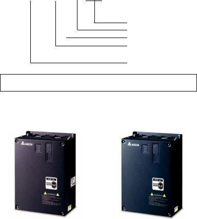
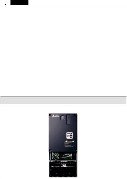
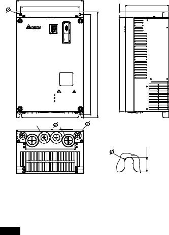
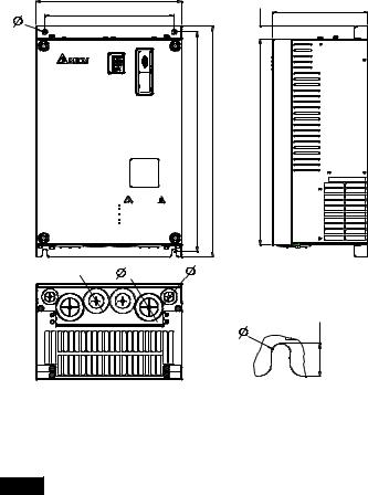
1.1.4 Drive Frames and Appearances
7.5-15HP/5.5-11kW(Frame C) |
20-30HP/15-22kW(Frame D) |
|
|
|
|
Revision Nov. 2008, VLE1, SW V1.03 |
1-3 |
Chapter 1 Introduction|
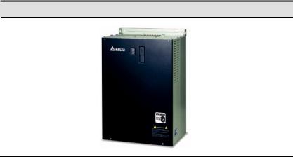
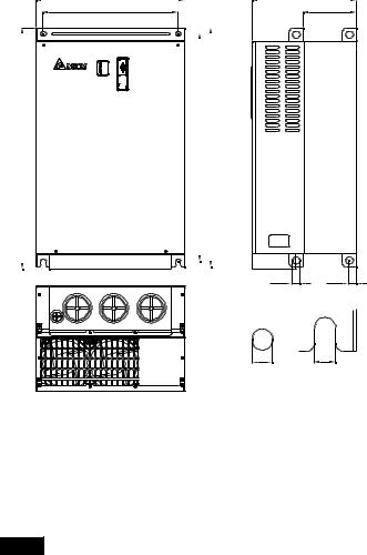
40-100HP/30-75kW(Frame E)
|
Frame |
Power range |
Models |
|
C |
7.5-15HP (5.5-11kW) |
VFD055VL23A/43A, VFD075VL23A/43A, |
|
VFD110VL23A/43A |
||
|
|
|
|
|
D |
20-30HP (15-22kW) |
VFD150VL23A/43A, VFD185VL23A/43A, |
|
VFD220VL23A/43A |
||
|
|
|
|
|
E (E1) |
40-60hp (30-45kW) |
VFD300VL43A, VFD370VL43A, VFD450V43A |
|
|
|
|
|
E (E2) |
40-100hp (30-75kW) |
VFD300VL23A, VFD370VL23A, VFD550VL43A, |
|
VFD750VL43A |
||
|
|
|
Please refer to Chapter 1.3 for exact dimensions.
1-4 |
Revision Nov. 2008, VLE1, SW V1.03 |
Chapter 1 Introduction|
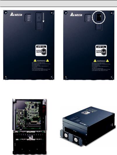
1.1.5 Drive Features
Communication Port
Internal structure |
Removable fan |
|
|
|
|
Revision Nov. 2008, VLE1, SW V1.03 |
1-5 |
Chapter 1 Introduction|
1.2 Preparation for Installation and Wiring
1.2.1 Ambient Conditions
Install the AC motor drive in an environment with the following conditions:
|
Air Temperature: |
|
-10 ~ +45°C (14 ~ 113°F) |
|
|
Relative Humidity: |
<90%, no condensation allowed |
||
|
|
|
|
|
Operation |
Atmosphere |
|
86 ~ 106 kPa |
|
pressure: |
|
|
||
|
|
|||
|
Installation Site |
<1000m |
||
|
Altitude: |
|||
|
|
|
||
|
Vibration: |
|
<20Hz: 9.80 m/s2 (1G) max |
|
|
|
20 ~ 50Hz: 5.88 m/s2 (0.6G) max |
|
|
|
|
|||
|
Temperature: |
-20°C ~ +60°C (-4°F ~ 140°F) |
||
|
|
|
||
Storage |
Relative Humidity: |
|
<90%, no condensation allowed |
|
Transportation |
Atmosphere |
86 ~ 106 kPa |
||
|
pressure: |
|||
|
|
|
||
|
Vibration: |
|
<20Hz: 9.80 m/s2 (1G) max |
|
|
|
20 ~ 50Hz: 5.88 m/s2 (0.6G) max |
||
|
|
|||
Pollution Degree 2: good for a factory type environment.
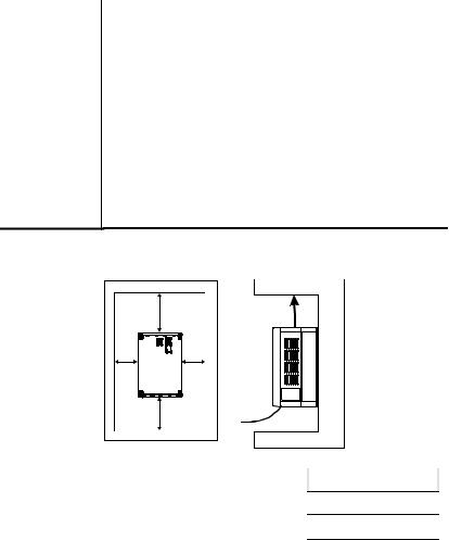
Minimum Mounting Clearances
H |
Air Flow |
W |
W |
H |
|
|
HP |
W |
H |
|
|
mm (inch) |
mm (inch) |
|
|
|
|
|
||
|
7.5-20HP |
75 (3) |
175 (7) |
|
|
|
|
|
|
|
25-75HP |
75 (3) |
200 (8) |
|
|
|
|
|
|
|
100HP |
75 (3) |
250 (10) |
|
|
|
|
|
|
1-6 |
Revision Nov. 2008, VLE1, SW V1.03 |
Chapter 1 Introduction|
 CAUTION!
1.Operating, storing or transporting the AC motor drive outside these conditions may cause damage to the AC motor drive.
2.Failure to observe these precautions may void the warranty!
3.Mount the AC motor drive vertically on a flat vertical surface object by screws. Other directions are not allowed.
4.The AC motor drive will generate heat during operation. Allow sufficient space around the unit for heat dissipation.
5.The heat sink temperature may rise to 90°C when running. The material on which the AC motor drive is mounted must be noncombustible and be able to withstand this high temperature.
6.When AC motor drive is installed in a confined space (e.g. cabinet), the surrounding temperature must be within 10 ~ 40°C with good ventilation. DO NOT install the AC motor drive in a space with bad ventilation.
7.Prevent fiber particles, scraps of paper, saw dust, metal particles, etc. from adhering to the heatsink.
8.When installing multiple AC more drives in the same cabinet, they should be adjacent in a row with enough space in-between. When installing one AC motor drive below another one, use a metal separation between the AC motor drives to prevent mutual heating.
1.2.2Remove Front Cover
7.5-15HP/5.5-11kW(frame C) & 20-30HP/15-22kW(frame D)
After removing the screws, please push the front cover to open it. For the open cover direction, please refer to the following picture.
Revision Nov. 2008, VLE1, SW V1.03 |
1-7 |
Chapter 1 Introduction|
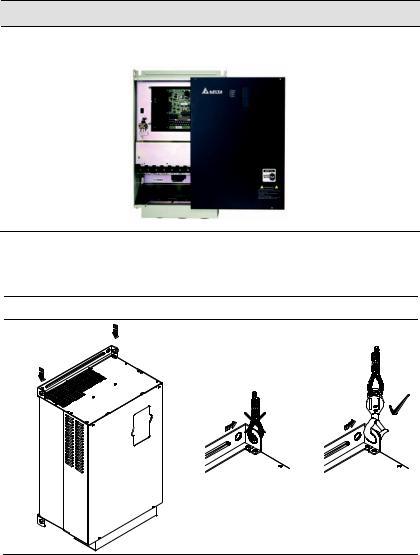
40-100HP/30-75kW (frame E)
After removing the screws, please push the front cover to open it. For the open cover direction, please refer to the following picture.
1.2.3 Lifting
Please carry only fully assembled AC motor drives as shown in the following.
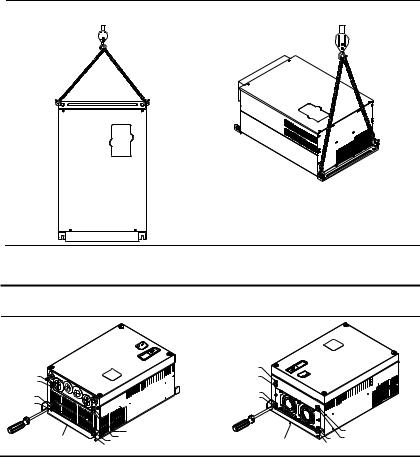
For 40-100HP (Frame E)
Step 1 Step 2
1-8 |
Revision Nov. 2008, VLE1, SW V1.03 |
Chapter 1 Introduction|
Step 3 |
|
Step 4 |
|
|
|
|
|
|
|
|
|
|
|
|
|
|
|
|
|
|
|
|
|
|
|
|
|
|
|
|
|
|
|
|
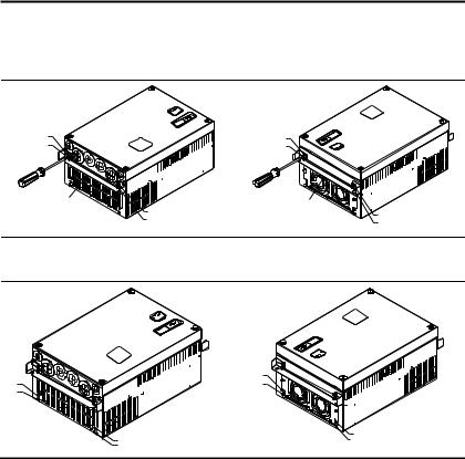
1.2.4 Flange Mounting
Step 1: Please take out the 16 screws (8 screws for each top and bottom side of the drive) and remove the fixed plate 1 and fixed plate 2) as shown in the following figures.
1 |
|
|
1 |
|
|
|
2 |
|
|
2 |
|
|
5 |
|
5 |
|
|
|
|
|
|
6 |
|
|
6 |
|
|
|
|
|
|
|
|
|
|
|
7 4 3 |
|
3 |
fixed plate 1 |
8 |
fixed pl ate 2 |
7 4 |
|
|
|
|
8 |
Revision Nov. 2008, VLE1, SW V1.03 |
1-9 |
Chapter 1 Introduction|
Step 2: place the 8 screws back in to secure the fixed plate 1 and fixed plate 2 (as shown in the following figures) with the following torque.
Frame C: 14-17kgf-cm [12.2-14.8in-lbf]
Frame D: 20-25kgf-cm [17.4-21.7in-lbf]
Frame E: 20-25kgf-cm [17.4-21.7in-lbf]
1 |
|
1 |
|
2 |
|
2 |
|
fixed plate 1 |
3 |
fixed plate 2 |
3 |
|
4 |
|
4 |
Step 3: Please notice that it doesn’t need to put those 8 screws shown in the following figures back to the drive. Moreover, please make sure that these 2 different fixed plates are put in the correct side as shown in the figures.
1 |
5 |
|
6 |
||
2 |
||
|
||
3 |
7 |
|
4 |
8 |
|
|
1-10 |
Revision Nov. 2008, VLE1, SW V1.03 |
Chapter 1 Introduction|
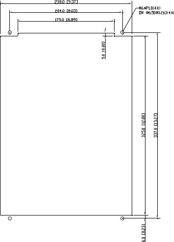
1.2.5 Cutout Dimensions
7.5-15HP/5.5-11kW (frame C)
Revision Nov. 2008, VLE1, SW V1.03 |
1-11 |
Chapter 1 Introduction|
20-30HP/15-22kW (frame D) |
1-12 |
Revision Nov. 2008, VLE1, SW V1.03 |
Chapter 1 Introduction|
1.3 Dimensions
Frame C
W
W1 |
D |
H3 
H
H1 H2
 WARNING
R ead the us er manual before operation.
R is k of electr ical s hock. Wait 10 m inutes after rem oving pow er before servic ing.
D o not c onnect AC power t o output ter minals U /T 1, V/T 2 and W /T 3.
U se proper gr ounding techniques.
C heck to be s ure that t he voltage of the main AC power supply satis fies t he rat ed voltage of the I nverter.
 2 1 3
2 1 3
Unit: mm [inch]
|
Frame |
W |
W1 |
H |
H1 |
H2 |
H3 |
D |
Ø |
Ø1 |
Ø2 |
Ø3 |
|
|
|
|
|
|
|
|
|
|
|
|
|
|
C |
235 |
204 |
350 |
337 |
320 |
- |
136 |
6.5 |
- |
34 |
22 |
|
[9.25] |
[8.03] |
[13.78] |
[13.27] |
[12.60] |
[5.35] |
[0.26] |
[1.34] |
[0.87] |
|||
|
|
|
|
|||||||||
|
|
|
|
|
|
|
|
|
|
|
|
|


 NOTE
NOTE
Frame C: VFD055VL23A/43A, VFD075VL23A/43A, VFD110VL23A/43A
Revision Nov. 2008, VLE1, SW V1.03 |
1-13 |
Chapter 1 Introduction|
Frame D
W
W1 |
D |
H3 
H
H1 H2
 WARNING
R ead the us er manual before operation.
R is k of electr ical s hock. Wait 10 m inutes after rem oving pow er before servic ing.
D o not c onnect AC power t o output ter minals U /T 1, V/T 2 and W /T 3.
U se proper gr ounding techniques.
C heck to be s ure that t he voltage of the main AC power supply satis fies t he rat ed voltage of the I nverter.
 2 1 3
2 1 3
Unit: mm [inch]
Frame |
W |
W1 |
H |
H1 |
H2 |
H3 |
D |
Ø |
Ø1 |
Ø2 |
Ø3 |
|
D |
255.0 |
226.0 |
403.8 |
384.0 |
360.0 |
21.9 |
168.0 |
8.5 |
44 |
34 |
22 |
|
[10.04] |
[8.90] |
[15.90] |
[15.12] |
[14.17] |
[0.86] |
[6.61] |
[0.33] |
[1.73] |
[1.34] |
[0.87] |
||
|
||||||||||||
|
|
|
|
|
|
|
|
|
|
|
|


 NOTE
NOTE
Frame D: VFD150VL23A/43A, VFD185VL23A/43A, VFD220VL23A/43A
1-14 |
Revision Nov. 2008, VLE1, SW V1.03 |
Chapter 1 Introduction|
Frame E
W |
|
|
|
D |
W1 |
|
|
D1 |
|
|
|
|
|
|
|
|
|
|
|
|
|
|
H |
|
|
|
H2 |
|
H1 |
|
|
|
|
|||||
|
|
|
|
|
|
|
|
|
|
|
|
|
|
|
|
|
|
|
|
|
|
|
|
|
|
|
|
|
|
|
|
S3 D2
S1 S2
Unit: mm [inch]
Frame |
W |
W1 |
H |
H1 |
H2 |
D |
D1 |
D2 |
S1 |
S2 |
S3 |
|
|
|
|
|
|
|
|
|
|
|
|
|
|
E1 |
370.0 |
335.0 |
- |
589.0 |
560.0 |
260.0 |
132.5 |
18.0 |
13.0 |
13.0 |
18.0 |
|
[14.57] |
[13.19] |
[23.19] |
[22.05] |
[10.24] |
[5.22] |
[0.71] |
[0.51] |
[0.51] |
[0.71] |
|||
|
|
|||||||||||
|
|
|
|
|
|
|
|
|
|
|
|
|
E2 |
370.0 |
335.0 |
595.0 |
589.0 |
560.0 |
260.0 |
132.5 |
18.0 |
13.0 |
13.0 |
18.0 |
|
[14.57] |
[13.19] |
[23.43] |
[23.19] |
[22.05] |
[10.24] |
[5.22] |
[0.71] |
[0.51] |
[0.51] |
[0.71] |
||
|
||||||||||||
|
|
|
|
|
|
|
|
|
|
|
|


 NOTE
NOTE
Frame E1: VFD300VL43A, VFD370VL43A, VFD450VL43A
Frame E2: VFD300VL23A, VFD370VL23A, VFD550VL43A, VFD750VL43A
Revision Nov. 2008, VLE1, SW V1.03 |
1-15 |
Chapter 1 Introduction|
This page intentionally left blank
1-16 |
Revision Nov. 2008, VLE1, SW V1.03 |

Chapter 2 Installation and Wiring
After removing the front cover (see chapter 1.2.2 for details), check if the power and control terminals are clear. Be sure to observe the following precautions when wiring.
 CAUTION!
1.Make sure that power is only applied to the R/L1, S/L2, T/L3 terminals. Failure to comply may result in damage to the equipment. The voltage and current should lie within the range as indicated on the nameplate.
2.Check the following items after finishing the wiring:
A.Are all connections correct?
B.No loose wires?
C.No short-circuits between terminals or to ground?
 DANGER!
1.A charge may still remain in the DC bus capacitors with hazardous voltages even if the power has been turned off. To prevent personal injury, please ensure that the power is turned off and wait ten minutes for the capacitors to discharge to safe voltage levels before opening the AC motor drive.
2.All the units must be grounded directly to a common ground terminal to prevent lightning strike or electric shock.
3.Only qualified personnel familiar with AC motor drives is allowed to perform installation, wiring and commissioning.
4.Make sure that the power is off before doing any wiring to prevent electric shock.
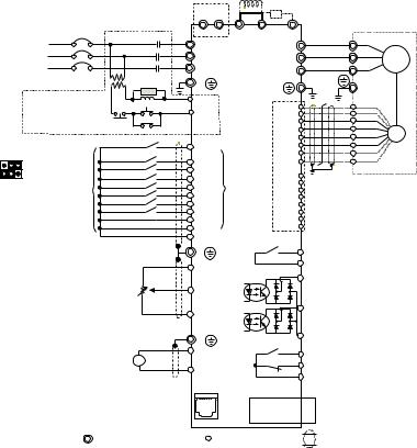
2.1 Wiring
Users must connect wires according to the circuit diagrams on the following pages. Do not plug a modem or telephone line to the RS-485 communication port or permanent damage may result. Pins 1 & 2 are the power supply for the optional copy keypad only and should not be used for RS485 communication.
Revision Nov. 2008, VLE1, SW V1.03 |
2-1 |
Chapter 2 Installation and Wiring|
|
|
* |
|
|
|
EPS |
|
Fus e/NFB(No Fuse B reaker) |
MC |
+ - |
|
R NFB |
|||
|
R(L1) |
||
S |
|
S(L2) |
|
T |
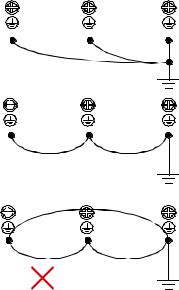
|
T(L3) |
|
Brake res istor |
|
||
|
(optional) Brak e res istor/Unit(optional) |
|||
|
|
|
Refer to Appendi x B for the us e of |
|
|
|
|
special brake resi stor/uni t |
|
+1 |
+2/B1 |
B2 |
U |
Motor |
|
U(T 1) |
|||
|
V |
|
||
|
|
V(T 2) |
IM/PM |
|
|
|
W |
||
|
W( T3) |
|||
|
|
|||
|
|
|
SA |
E |
|
E |
|
|
|
|
|
||
Recommended Circuit |
RB |
|
|
|||
MC |
|
|
||||
when power s uppl y |
|
|
RC |
|
onal) |
|
fault output |
OFF |
ON |
|
|||
is turned O FF by a |
|
|
|
|
||
|
|
|
MC |
|
|
(opti |
Factory setting: |
|
Forwa rd/S TOP |
FW D |
|
||
SINK Mode |
|
Reverse/STOP |
|
|
Card |
|
* |
|
Multi-st ep 1 |
|
REV |
|
|
|
Multi-st ep 2 |
|
MI1 |
|
PG |
|
|
|
Multi-st ep 3 |
|
MI2 |
multifunction |
|
|
Fac tory |
|
MI3 |
|
||
|
Multi -st ep 4 |
|
|
|||
|
|
te rmin als |
|
|||
Please refer to the |
setting |
No function |
|
MI4 |
|
|
|
|
|
||||
following figure for wiring |
No function |
|
MI5 |
|
|
|
|
MI6 |
|
|
|||
of S INK mode and SOURCE |
No function |
|
|
|
||
|
MI7 |
|
|
|||
mode. |
|
No function(*1) |
|
|
||
|
MI8(*1) |
|
|
|||
|
|
Digit al Signal Common |
|
|
||
|
|
COM |
|
|
||
|
|
|
|
|
MRA |
|
|
|
|
|
E |
|
|
|
|
|
|
|
MRC |
|
|
|
|
|
+10V |
|
|
|
|
|
|
|
|
|
|
|
|
|
Power supply |
|
|
|
|
|
|
+10V 20mA |
|
|
|
|
|
|
AUI1/AUI2 |
|
|
|
|
|
|
Mast er |
|
|
|
|
|
|
Frequency |
|
|
|
|
|
|
-10 to 10V |
|
|
|
|
|
|
-10V |
|
|
|
|
|
|
Power supply |
|
|
|
|
|
|
-10V 20mA |
|
|
|
|
E |
|
|
A 4~20mA |
ACI |
|
||
ACM |
||||
|
|
|||
|
1: +EV |
1 2 3 4 |
5 6 |
|
*RS-485 |
2: GND |
|||
To communicate to PC, it needs |
3: SG- |
|
|
|
to use converter (VFD-USB01 or |
4: SG+ |
|
|
|
IFD8500). |
5: NC |
|
6: NC |
||
|
RA
RB
RC
EMVL -I OD01 extension c ard (optional)
PG
Line drive r
increment al encode r
PG Card (o ption al)
EMV L-PGABL
EMV L-PGABO
EMV L-PGH01
Multi-function cont ac t out put 2 (Relay ) 240VAC 3A
120VAC 3A
24VD C 3A factory setting:
indicates that it is running
MO1
Multi-function cont ac t out put 3
(photocoupler) 48VD C 50mA
MO2
Multi-function cont ac t out put 4 (photocoupler)
MCM
Multi-function
Phot oc oupler Output
Multi-function cont ac t output 1 (Relay) 240VAC 3A
120VAC 3A 24VD C 3A
factory setting: fault indic at ion
Main circuit (pow er) terminals |
Control circuit term inals |
Shielded leads & C able |
* Terminal EPS is eme rg ency power inp ut terminal, refer to t he following figure for de tails.
* For PG card, refe r to Ap pendix B for deta ils.
(*1 ) When JP1  on the control board is inserted, MI8 is disabled.
2-2 |
Revision Nov. 2008, VLE1, SW V1.03 |
Chapter 2 Installation and Wiring|
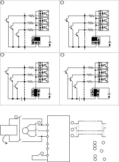
Figure 2 Wiring/Terminals setting for SINK(NPN) mode and SOURCE(PNP) mode
1 |
Sink (NPN) mode |
2 |
Source (PNP) mode |
|
|
used with internal power (+24Vdc) |
|
used with internal power (+24Vdc) |
|
|
MI1 |
|
MI1 |
|
|
MI2 |
|
MI2 |
|
|
~ |
|
~ |
|
|
MI8 |
|
MI8 |
|
|
+24V |
|
|
+24V |
|
COM |
|
|
COM |
3 |
Sink (NPN) mode |
4 |
Source (PNP) mode |
|
|
used with external power |
|
used with external power |
|
|
MI1 |
|
MI1 |
|
|
MI2 |
|
MI2 |
|
|
~ |
|
~ |
|
|
MI8 |
|
MI8 |
|
|
+24V |
|
|
+24V |
|
+ COM |
|
+ |
COM |
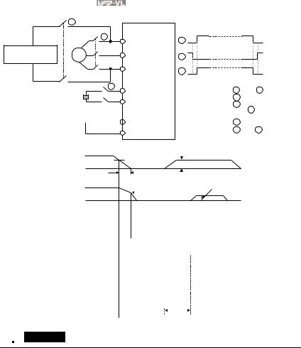
Figure 3 Apply to 1-phase UPS power supply system
1 |
|
AC motor driv e |
|
|
|
||
|
Main power 2 |
R/L1 |
|
|
|
||
1-phase UP S |
3 |
S/L2 |
|
or battery |
~ |
||
|
|
T/L3 |
|
Specifications for |
EPS/+ |
||
1-phase UP S and battery |
|||
EPS/- |
|||
250VDC (for 230V series) |
|||
500VDC (for 460V series) |
3 |
||
|
|
||
To input emergency power
MI1~8
 COM
COM
Timing diagram of M.C. (magnetic contac t or)
1
2
3
Before i nputting emergency power, magnetic c ontactor 1 and 3 are ON and
magnetic c ontactor 2 |
s hould be O FF. |
|
Magnetic c ontactor 3 |
s hould be O N |
|
after magnetic c ontactor 1 |
is ON. |
|
Before removing battery and turn |
||
magnetic c ontactor 2 |
to be ON, |
|
magnetic c ontactor 1 |
and |
3 shoul d be |
OFF. |
|
|
Revision Nov. 2008, VLE1, SW V1.03 |
2-3 |
Chapter 2 Installation and Wiring|
Figure 4 Apply to two batteries with main battery voltage is lower than 280Vdc
1
AC motor driv e
|
Main |
2 |
R/L1 |
|
power |
|
|
|
|
|
|
48V dc (230V Se rie s) |
3 |
|
S/L2 |
96V dc (460V Se rie s) |
~ |
|
|
|
|
||
|
|
|
T /L3 |
|
|
|
3 |
1-phase UP S or battery |
|
EPS/+ |
|
|
|
||
Specific ations for |
|
|
EPS/- |
1-phase UP S and battery |
|
|
|
250VDC (for 230V series)
500VDC (for 460V series) MI1~8
MI1~8
COM
To input emergency power
Timing diagram of M.C. (magnetic contac t or)
1
2
3
Before inputting emer gency power,
magneti c c ontactor 1 |
and |
3 |
are ON and |
magneti c c ontactor 2 |
should be O FF. |
||
Magneti c c ontactor 3 |
should be O N |
||
after magnetic contac tor 1 |
is ON. |
||
Before removing battery and turn |
|||
magneti c c ontactor 2 |
to be O N, |
||
magneti c c ontactor 1 |
and |
3 |
should be |
OFF. |
|
|
|
DC voltage |
|
low voltage level |
|
battery voltage |
||||||||||
|
||||||||||||||
free |
|
|
|
|
|
|
||||||||
|
|
|
|
|
|
|
|
|
|
|
||||
|
|
|
run |
|
|
|
default EPS operation |
|||||||
motor speed |
|
|
|
|
|
mechanical brakefrequency |
||||||||
|
|
|
|
|
||||||||||
|
|
|
|
|
|
|
|
|
|
|
|
|
||
|
|
|
|
|
|
|
|
|
|
|
|
|
||
error output |
|
|
|
|
|
|
|
|
|
|
|
|
|
|
|
|
|
|
|
|
|
|
|
|
|
|
|
|
|
|
|
|
|
|
|
|
|
|
|
|
|
|
|
|
electromagnetic |
|
|
|
|
OFF |
|
|
|
|
|
|
|
||
|
|
|
|
|
|
|
|
|
|
|
||||
valve |
|
|
|
|
|
|
|
|
|
|
|
|
|
|
|
|
|
|
|
|
|
|
|
|
|
|
|
|
|
operation |
|
|
|
|
|
|
|
|
|
|
|
|
|
|
command |
|
|
|
|
|
|
|
|
|
|
about 1 min. |
|
|
|
|
|
|
|
|
|
|
|
|
|
|||||
|
|
|
|
|
|
|
|
|
|
|
|
|
|
|
EPS detection |
|
|
|
|
|
|
|
|
|
|||||
|
|
|
|
|
|
ON |
|
|
||||||
MI-COM=43 |
|
|
|
|
|
|
|
|
|
|
|
|
|
|
|
|
|
|
|
|
|
|
|
|
|
|
|
|
|
electromagnetic |
|
|
|
|
|
|
|
|
|
|||||
|
|
|
|
|
|
ON |
|
|
||||||
valve |
|
|
|
|
|
|
|
|
|
|
|
|
|
|
drive ready |
|
|
|
|
|
|
|
|
|
|
|
|
|
|
MO-COM=9 |
|
|
|
|
|
|
|
ON |
|
|||||
|
|
|
|
|
|
|
|
|
|
|
|
|
|
|
|
|
|
|
|
|
|
|
about 2 sec. |
||||||
 CAUTION!
1.The wiring of main circuit and control circuit should be separated to prevent erroneous actions.
2.Please use shield wire for the control wiring and not to expose the peeled-off net in front of the terminal.
3.Please use the shield wire or tube for the power wiring and ground the two ends of the shield wire or tube.
4.Damaged insulation of wiring may cause personal injury or damage to circuits/equipment if it comes in contact with high voltage.
2-4 |
Revision Nov. 2008, VLE1, SW V1.03 |
Chapter 2 Installation and Wiring|
5.The AC motor drive, motor and wiring may cause interference. To prevent the equipment damage, please take care of the erroneous actions of the surrounding sensors and the equipment.
6.When the AC drive output terminals U/T1, V/T2, and W/T3 are connected to the motor terminals U/T1, V/T2, and W/T3, respectively. To permanently reverse the direction of motor rotation, switch over any of the two motor leads.
7.With long motor cables, high capacitive switching current peaks can cause over-current, high leakage current or lower current readout accuracy. For longer motor cables use an AC output reactor.
8.The AC motor drive, electric welding machine and the greater horsepower motor should be grounded separately.
9.Use ground leads that comply with local regulations and keep them as short as possible.
10.No brake resistor is built in the VFD-VL series, it can install brake resistor for those occasions that use higher load inertia or frequent start/stop. Refer to Appendix B for details.
11.Multiple VFD-VL units can be installed in one location. All the units should be grounded directly to a common ground terminal, as shown in the figure below. Ensure there are no ground
loops.
grouning terminals
Excellent
grouning  terminals


Good
grouning  terminals

Not allowed
Revision Nov. 2008, VLE1, SW V1.03 |
2-5 |
Loading...