

Page 1
Page 2
Page 3

Page 4

Preface
Thank you for choosing DELTA’s high-performance VFD-VE Series. The VFD-VE Series is
manufactured with high-quality components and materials and incorporates the latest
microprocessor technology available.
This manual is to be used for the installation, parameter setting, troubleshooting, and daily
maintenance of the AC motor drive. To guarantee safe operation of the equipment, read the following
safety guidelines before connecting power to the AC motor drive. Keep this operating manual at
hand and distribute to all users for reference.
To ensure the safety of operators and equipment, only qualified personnel familiar with AC motor
drive are to do installation, start-up and maintenance. Always read this manual thoroughly before
using VFD-VE series AC Motor Drive, especially the WARNING, DANGER and CAUTION notes.
Failure to comply may result in personal injury and equipment damage. If you have any questions,
please contact your dealer.
PLEASE READ PRIOR TO INSTALLATION FOR SAFETY.
DANGER!
1. AC input power must be disconnected before any wiring to the AC motor drive is made.
2. A charge may still remain in the DC-link capacitors with hazardous voltages, even if the power
has been turned off. To prevent personal injury, please ensure that power has turned off before
opening the AC motor drive and wait ten minutes for the capacitors to discharge to safe voltage
levels.
3. Never reassemble internal components or wiring.
4. The AC motor drive may be destroyed beyond repair if incorrect cables are connected to the
input/output terminals. Never connect the AC motor drive output terminals U/T1, V/T2, and
W/T3 directly to the AC mains circuit power supply.
5. Ground the VFD-VE using the ground terminal. The grounding method must comply with the
laws of the country where the AC motor drive is to be installed. Refer to the Basic Wiring
Diagram.
6. VFD-VE series is used only to control variable speed of 3-phase induction motors, NOT for 1-
phase motors or other purpose.
7. VFD-VE series shall NOT be used for life support equipment or any life safety situation.
Page 5

WARNI NG!
1. DO NOT use Hi-pot test for internal components. The semi-conductor used in AC motor drive
easily damage by high-voltage.
2. There are highly sensitive MOS components on the printed circuit boards. These components
are especially sensitive to static electricity. To prevent damage to these components, do not
touch these components or the circuit boards with metal objects or your bare hands.
3. Only qualified persons are allowed to install, wire and maintain AC motor drives.
CAUTION!
1. Some parameters settings can cause the motor to run immediately after applying power.
2. DO NOT install the AC motor drive in a place subjected to high temperature, direct sunlight,
high humidity, excessive vibration, corrosive gases or liquids, or airborne dust or metallic
particles.
3. Only use AC motor drives within specification. Failure to comply may result in fire, explosion or
electric shock.
4. To prevent personal injury, please keep children and unqualified people away from the
equipment.
5. When the motor cable between AC motor drive and motor is too long, the layer insulation of the
motor may be damaged. Please use a frequency inverter duty motor or add an AC output
reactor to prevent damage to the motor. Refer to appendix B Reactor for details.
6. The rated voltage for AC motor drive must be ≤ 240V (≤ 480V for 460V models) and the mains
supply current capacity must be ≤ 5000A RMS (≤10000A RMS for the ≥ 40hp (30kW) models).
Page 6

Table of Contents
Preface ............................................................................................................. i
Table of Contents .......................................................................................... iii
Chapter 1 Introduction................................................................................ 1-1
1.1 Receiving and Inspection ...................................................................1-2
1.1.1 Nameplate Information................................................................ 1-2
1.1.2 Model Explanation ...................................................................... 1-2
1.1.3 Series Number Explanation ........................................................ 1-3
1.1.4 Drive Frames and Appearances ................................................. 1-3
1.2 Preparation for Installation and Wiring ............................................... 1-4
1.2.1 Ambient Conditions..................................................................... 1-4
1.2.2 Remove Keypad ......................................................................... 1-6
1.2.3 Remove Front Cover................................................................... 1-7
1.2.4 Lifting .......................................................................................... 1-8
1.3 Dimensions......................................................................................... 1-9
Chapter 2 Installation and Wiring .............................................................. 2-1
2.1 Wiring ................................................................................................. 2-2
2.2 External Wiring ................................................................................... 2-4
2.3 Main Circuit ........................................................................................2-5
2.3.1 Main Circuit Connection.............................................................. 2-5
2.3.2 Main Circuit Terminals ................................................................ 2-9
Page 7

2.4 Control Terminals .............................................................................2-10
Chapter 3 Digital Keypad Operation and Start Up ....................................3-1
3.1 Digital Keypad KPV-CE01 ..................................................................3-1
3.1.1 Description of the Digital Keypad KPV-CE01 .............................. 3-1
3.1.2 How to Operate the Digital Keypad KPV-CE01........................... 3-3
3.1.3 Dimension of the Digital Keypad .................................................3-5
3.1.4 Reference Table for the LCD Display of the Digital Keypad........ 3-5
3.1.5 Operation Method........................................................................ 3-6
3.2 Start-up...............................................................................................3-6
3.2.1 Preparations before Start-up ....................................................... 3-6
3.2.2 Trial Run...................................................................................... 3-8
Chapter 4 Parameters..................................................................................4-1
4.1 Summary of Parameter Settings......................................................... 4-2
4.2 Version Differences ..........................................................................4-26
4.2.1 Version 2.02 .............................................................................. 4-26
4.2.2 Version 2.04 .............................................................................. 4-26
4.3 Description of Parameter Settings ....................................................4-38
Chapter 5 Troubleshooting.........................................................................5-1
5.1 Over Current (OC) ..............................................................................5-1
5.2 Ground Fault.......................................................................................5-2
5.3 Over Voltage (OV) ..............................................................................5-2
5.4 Low Voltage (Lv).................................................................................5-3
5.5 Over Heat (oH1, oH2, oH3) ................................................................5-4
5.6 Overload ............................................................................................. 5-4
5.7 Display of KPV-CE01 is Abnormal......................................................5-5
Page 8

5.8 Phase Loss (PHL) ..............................................................................5-5
5.9 Motor cannot Run............................................................................... 5-6
5.10 Motor Speed cannot be Changed..................................................... 5-7
5.11 Motor Stalls during Acceleration....................................................... 5-8
5.12 The Motor does not Run as Expected .............................................. 5-8
5.13 Electromagnetic/Induction Noise ...................................................... 5-9
5.14 Environmental Condition ..................................................................5-9
5.15 Affecting Other Machines ............................................................... 5-10
Chapter 6 Fault Code Information and Maintenance................................ 6-1
6.1 Fault Code Information....................................................................... 6-1
6.1.1 Common Problems and Solutions............................................... 6-1
6.1.2 Reset .......................................................................................... 6-6
6.2 Maintenance and Inspections............................................................. 6-7
Appendix A Specifications ........................................................................ A-1
Appendix B Accessories ........................................................................... B-1
B.1 All Brake Resistors & Brake Units Used in AC Motor Drives..............B-1
B.1.1 Dimensions and Weights for Brake Resistors ............................ B-4
B.1.2 Specifications for Brake Unit ......................................................B-6
B.1.3 Dimensions for Brake Unit..........................................................B-7
B.2 No-fuse Circuit Breaker Chart ............................................................B-9
B.3 Fuse Specification Chart ..................................................................B-10
B.4 AC Reactor ......................................................................................B-11
B.4.1 AC Input Reactor Recommended Value................................... B-11
B.4.2 AC Output Reactor Recommended Value................................B-11
Page 9

B.4.3 Applications for AC Reactor......................................................B-13
B.5 Zero Phase Reactor (RF220X00A) ................................................. B-15
B.6 DC Choke Recommended Values................................................... B-16
B.7 Remote Controller RC-01 ................................................................ B-17
B.8 PG Card (for Encoder) .................................................................... B-18
B.8.1 EMV-PG01X .............................................................................B-18
B.8.2 EMV-PG01O.............................................................................B-21
B.8.3 EMV-PG01L..............................................................................B-25
B.9 AMD-EMI Filter Cross Reference .................................................... B-29
B.9.1 Dimensions ...............................................................................B-33
B.10 Multi-function I/O Extension Card.................................................. B-40
B.10.1 Functions ................................................................................B-40
B.10.2 Dimensions .............................................................................B-42
B.10.3 Wiring......................................................................................B-42
Appendix C How to Select the Right AC Motor Drive.............................. C-1
C.1 Capacity Formulas ............................................................................C-1
C.2 General Precaution ...........................................................................C-3
C.3 How to Choose a Suitable Motor....................................................... C-5
Page 10

Chapter 1 Introduction
The AC motor drive should be kept in the shipping carton or crate before installation. In order to
retain the warranty coverage, the AC motor drive should be stored properly when it is not to be used
for an extended period of time. Storage conditions are:
CAUTION!
1. Store in a clean and dry location free from direct sunlight or corrosive fumes.
2. Store within an ambient temperature range of -10
3. Store within a relative humidity range of 0% to 90% and non-condensing environment.
4. Store within an air pressure range of 86 kPA to 106kPA.
5. DO NOT place on the ground directly. It should be stored properly. Moreover, if the surrounding
environment is humid, you should put exsiccator in the package.
6. DO NOT store in an area with rapid changes in temperature. It may cause condensation and
frost.
7. If the AC motor drive is stored for more than 3 months, the temperature should not be higher
than 30 °C. Storage longer than one year is not recommended, it could result in the degradation
of the electrolytic capacitors.
8. When the AC motor drive is not used for longer time after installation on building sites or places
with humidity and dust, it’s best to move the AC motor drive to an environment as stated above.
°
C to +40 °C.
Revision August 2008, 03VE, SW V2.04 1-1
Page 11
Chapter 1 Introduction|
1.1 Receiving and Inspection
This VFD-VE AC motor drive has gone through rigorous quality control tests at the factory before
shipment. After receiving the AC motor drive, please check for the following:
Check to make sure that the package includes an AC motor drive, the User Manual/Quick
Start and CD.
Inspect the unit to assure it was not damaged during shipment.
Make sure that the part number indicated on the nameplate corresponds with the part
number of your order.
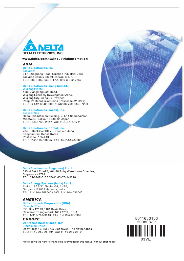
1.1.1 Nameplate Information
Example for 5HP/3.7kW 3-phase 230V AC motor drive
AC Drive Model
Input Spec.
Output Frequency Range
Serial Number & Bar Code
Output Spec.
Enclosure type
1.1.2 Model Explanation
VFD A-
V037
23
MODE : VFD037V23A-2
INPUT : 3PH 200-240V 50/60Hz 19.6A
OUTPUT :3PH 0-240V 17A 6.5kVA 5HP
Freq. Range : 0.00~600.00Hz
ENCLOSURE: TYPE 1
037V23A2T6360001
2
VFD-VE Series
Versi on Ty pe
Mains Input Voltage
23: Three phase230V 43: Three phase460V
Vec tor Series
Applicable motor capacity
007: 1 HP(0.7kW) 150: 20HP(15kW)
022: 3 HP(2.2kW) 220: 30 HP(22kW)
037: 5 HP(3.7kW) 300: 40HP(30kW)
055: 7.5HP(5.5kW) 370: 50 HP(37kW)
075: 10 HP(7.5kW) 450: 60HP(45kW)
110: 15 HP(11kW) 550: 75HP(55kW)
Series Name ( ariable requency rive)
750: 100HP(75kW)
VF D
1-2 Revision August 2008, 03VE, SW V2.04
Page 12
Chapter 1 Introduction|
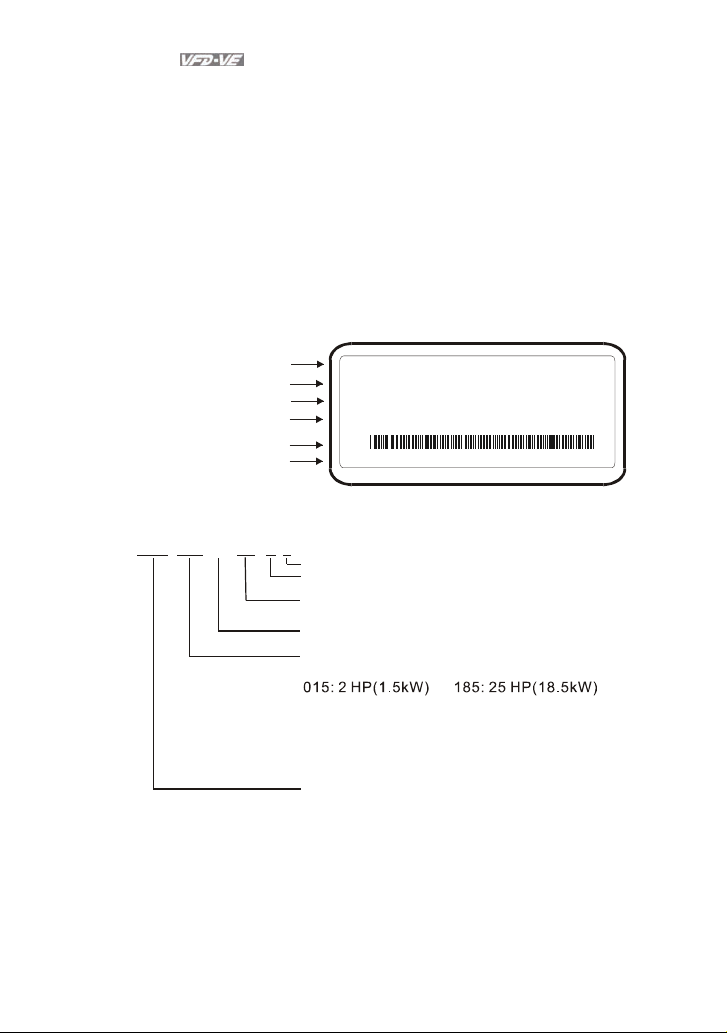
1.1.3 Series Number Explanation
367T037V23A2
Production number
Production week
Production year 2007
Production factory
230V 3-phase 5HP(3.7kW)
(T: Taoyuan, W: Wujian)
Model
If the nameplate information does not correspond to your purchase order or if there are
any problems, please contact your distributor.
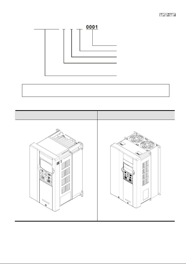
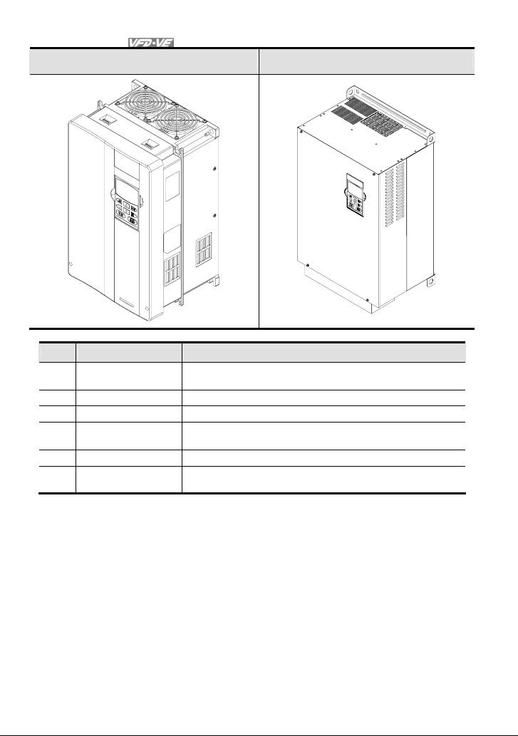
1.1.4 Drive Frames and Appearances
1-5HP/0.75-3.7kW (Frame B) 7.5-15HP/5.5-11kW (Frame C)
Revision August 2008, 03VE, SW V2.04 1-3
Page 13
Chapter 1 Introduction|
15-30HP/11-22kW (Frame D) 40-100HP/30-75kW (Frame E)
Frame Power range Models
B (B1) 1-3hp (0.75-2.2kW)
B (B2) 5hp (3.7kW) VFD037V23A/43A-2
C 7.5-15hp (5.5-11kW) VFD055V23A/43A-2, VFD075V23A/43A-2, VFD110V43B-2
D 15-30hp (11-22kW)
E (E1) 40-60hp (30-45kW) VFD300V43A-2, VFD370V43A-2, VFD450V43A-2
E (E2) 40-100hp (30-75kW)
Please refer to Chapter 1.3 for exact dimensions.
VFD007V23A/43A-2, VFD015V23A/43A-2,
VFD022V23A/43A-2
VFD110V23A/43A-2, VFD150V23A/43A-2,
VFD185V23A/43A-2, VFD220V23A/43A-2
VFD300V23A-2, VFD370V23A-2, VFD550V43C-2,
VFD750V43C-2
1.2 Preparation for Installation and Wiring
1.2.1 Ambient Conditions
Install the AC motor drive in an environment with the following conditions:
1-4 Revision August 2008, 03VE, SW V2.04
Page 14
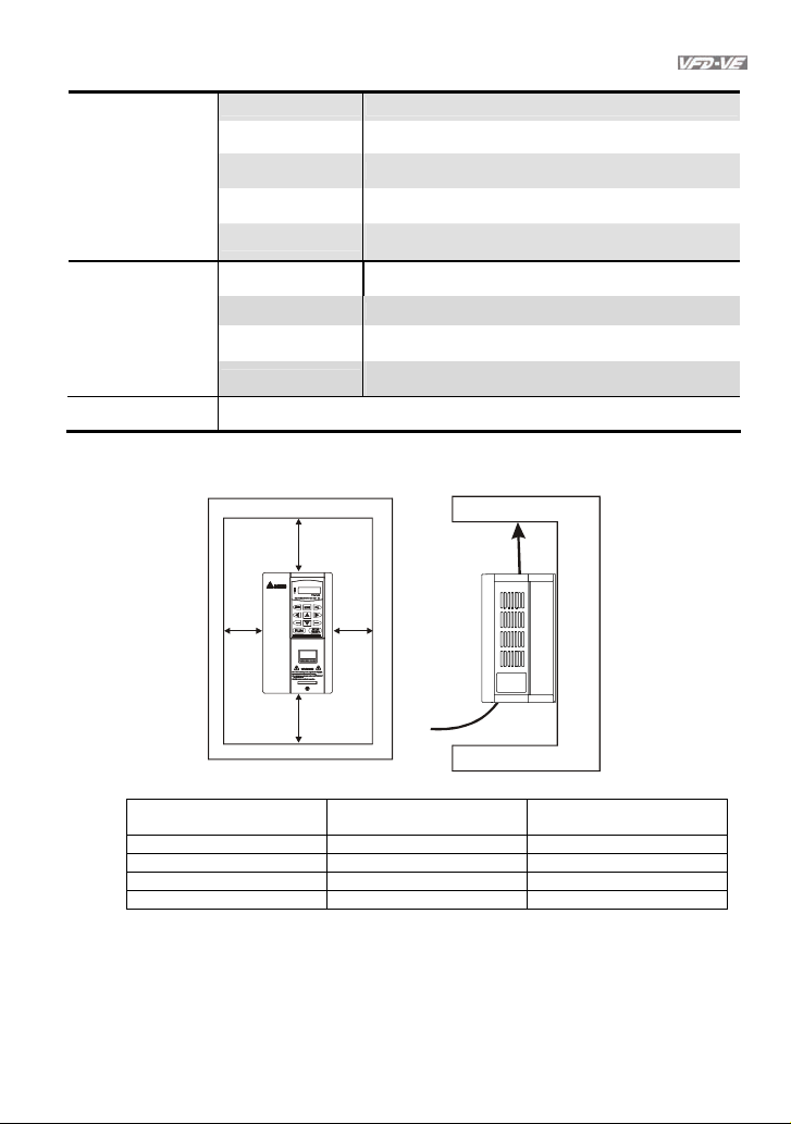
Air Temperature: -10 ~ +40°C (14 ~ 122°F)
Relative Humidity: <90%, no condensation allowed
Operation
Atmosphere
pressure:
Installation Site
Altitude:
Vibration:
86 ~ 106 kPa
<1000m
<20Hz: 9.80 m/s2 (1G) max
20 ~ 50Hz: 5.88 m/s2 (0.6G) max
Temperature: -20°C ~ +60°C (-4°F ~ 140°F)
Storage
Transportation
Relative Humidity: <90%, no condensation allowed
Atmosphere
pressure:
Vibration:
86 ~ 106 kPa
<20Hz: 9.80 m/s2 (1G) max
20 ~ 50Hz: 5.88 m/s2 (0.6G) max
Pollution Degree 2: good for a factory type environment.
Minimum Mounting Clearances
Chapter 1 Introduction|
H
FWD
PROG
REV
DATA
W
W
Air Flow
H
HP
W
mm (inch)
1-5HP 50 (2) 150 (6)
7.5-20HP 75 (3) 175 (7)
25-75HP 75 (3) 200 (8)
100HP and above 75 (3) 250 (10)
Revision August 2008, 03VE, SW V2.04 1-5
H
mm (inch)
Page 15
Chapter 1 Introduction|
CAUTION!
1. Operating, storing or transporting the AC motor drive outside these conditions may cause
damage to the AC motor drive.
2. Failure to observe these precautions may void the warranty!
3. Mount the AC motor drive vertically on a flat vertical surface object by screws. Other directions
are not allowed.
4. The AC motor drive will generate heat during operation. Allow sufficient space around the unit
for heat dissipation.
5. The heat sink temperature may rise to 90°C when running. The material on which the AC motor
drive is mounted must be noncombustible and be able to withstand this high temperature.
6. When AC motor drive is installed in a confined space (e.g. cabinet), the surrounding
temperature must be within -10 ~ 40°C with good ventilation. DO NOT install the AC motor
drive in a space with bad ventilation.
7. When installing multiple AC more drives in the same cabinet, they should be adjacent in a row
with enough space in-between. When installing one AC motor drive below another one, use a
metal separation between the AC motor drives to prevent mutual heating.
8. Prevent fiber particles, scraps of paper, saw dust, metal particles, etc. from adhering to the
heatsink.
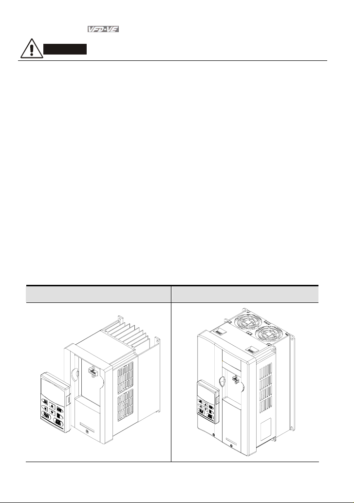
1.2.2 Remove Keypad
1-5HP/0.75-3.7kW (Frame B) 7.5-15HP/5.5-11kW (Frame C)
1-6 Revision August 2008, 03VE, SW V2.04
Page 16
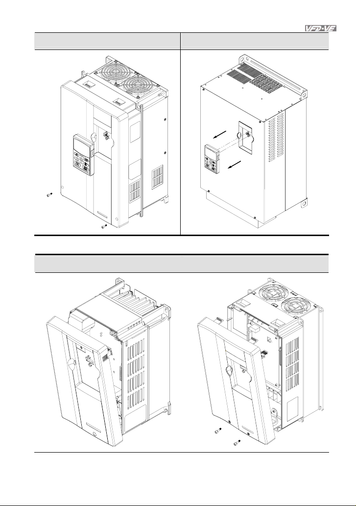
Chapter 1 Introduction|
15-30HP/11-22kW (Frame D) 40-100HP/30-75kW (Frame E)
1.2.3 Remove Front Cover
1-5HP/0.75-3.7kW (Frame B) 7.5-15HP/5.5-11kW (Frame C)
Revision August 2008, 03VE, SW V2.04 1-7
Page 17
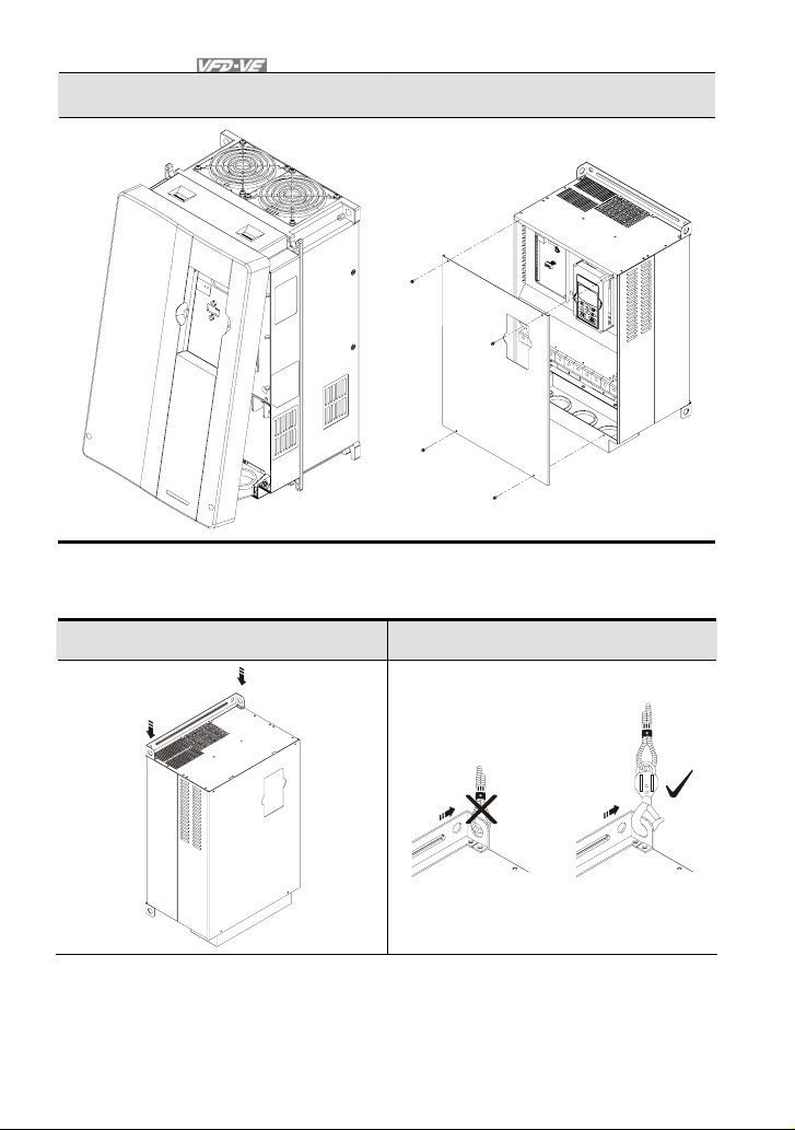
Chapter 1 Introduction|
15-30HP/11-22kW (Frame D) 40-100HP/30-75kW (Frame E)
1.2.4 Lifting
Please carry only fully assembled AC motor drives as shown in the following.
For 40-100HP (Frame E and E1)
Step 1 Step 2
1-8 Revision August 2008, 03VE, SW V2.04
Page 18
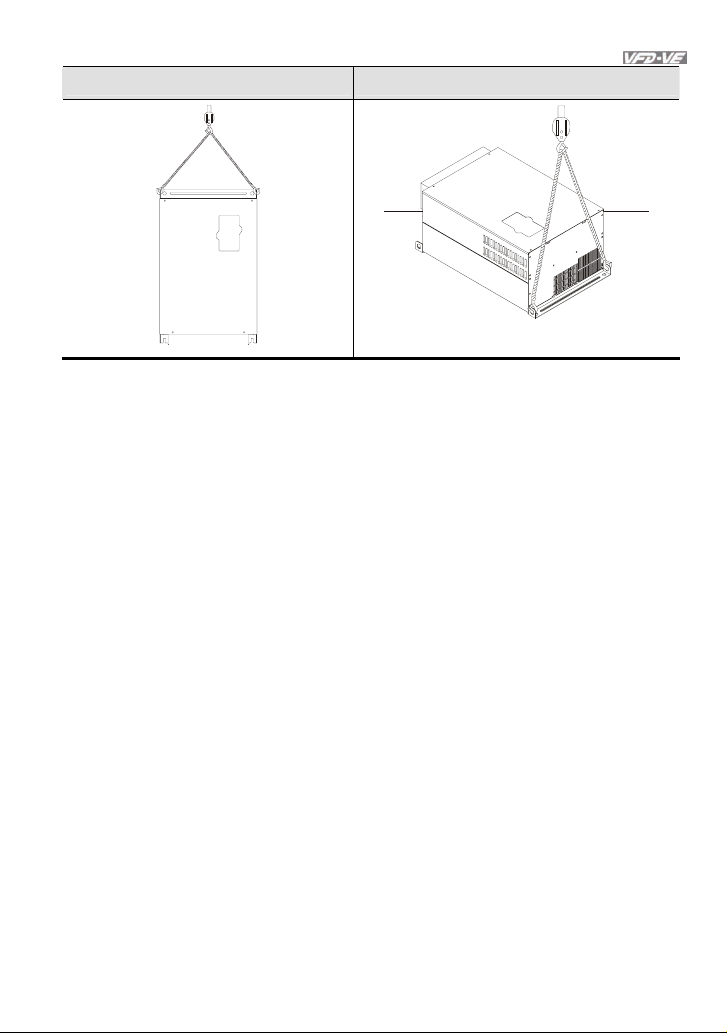
Step 3 Step 4
1.3 Dimensions
Chapter 1 Introduction|
Revision August 2008, 03VE, SW V2.04 1-9
Page 19
Chapter 1 Introduction|
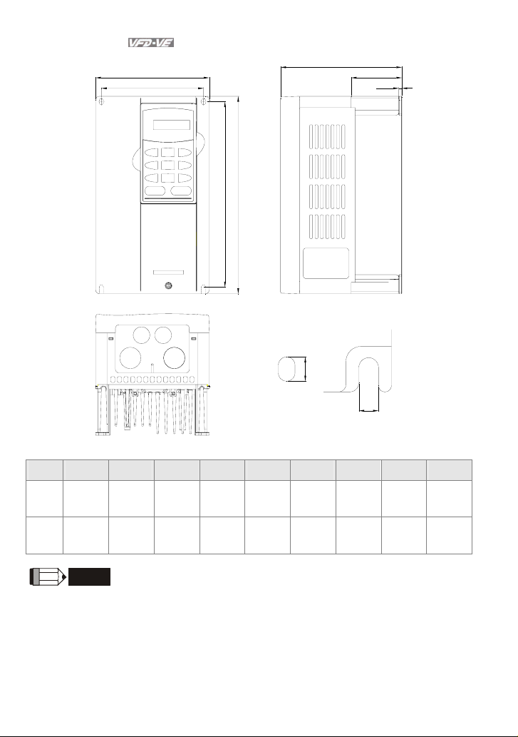
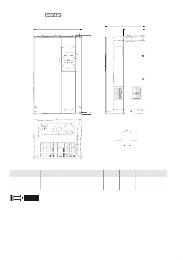
Frame B
W1
W
H
H1
D
D1
D2
S1
S2
Unit: mm[inch]
Frame W W1 H H1 D D1 D2 S1 S2
150.0
B1
[5.91]
150.0
B2
[5.91]
NOTE
Frame B1: VFD007V23A/43A-2, VFD015V23A/43A-2, VFD022V23A/43A-2
Frame B2: VFD037V23A/43A-2
1-10 Revision August 2008, 03VE, SW V2.04
135.0
[5.32]
135.0
[5.32]
260.0
[10.24]
272.1
[10.72]
244.3
[9.63]
244.3
[9.63]
160.2
[6.31]
183.7
[7.24]
67.0
[2.64]
67.0
[2.64]
4.0
[0.16]
4.0
[0.16]
8.0
[0.32]
8.0
[0.32]
6.5
[0.26]
6.5
[0.26]
Page 20
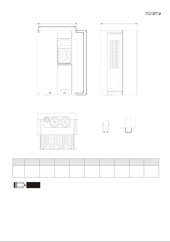
Frame C
Chapter 1 Introduction|
W
W1
H
H1
D
S1
S2
Unit: mm[inch]
Frame W W1 H H1 D - - S1 S2
C
200.0
[7.88]
NOTE
185.6
[7.31]
323.0
[12.73]
244.3
[9.63]
160.2
[6.31]
- [0.28]
7.0
7.0
[0.28]
Frame C: VFD055V23A/43A-2, VFD075V23A/43A-2, VFD110V43B-2
Revision August 2008, 03VE, SW V2.04 1-11
Page 21
Chapter 1 Introduction|
Frame D
W
W1
H
H1
D
D1
D2
S1
Unit: mm[inch]
Frame W W1 H H1 D D1 D2 S1 -
250.0
D
[9.85]
NOTE
Frame D: VFD110V23A/43A-2, VFD150V23A/43A-2, VFD185V23A/43A-2, VFD220V23A/43A-2
1-12 Revision August 2008, 03VE, SW V2.04
226.0
[8.90]
408.2
[16.07]
384.0
[15.13]
205.4
[8.08]
110.0
[4.33]
10.0
[0.39]
10.0
[0.39]
-
Page 22
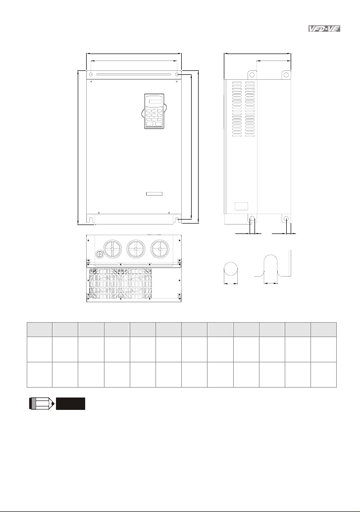
Frame E
Chapter 1 Introduction|
W D
W1
D1
H
H1
H2
S3
S1
D2
S2
Unit: mm[inch]
Frame W W1 H H1 H2 D D1 D2 S1 S2 S3
370.0
[14.57]
370.0
[14.57]
NOTE
335.0
[13.19]
335.0
[13.19]
E1
E2
Frame E1: VFD300V43A-2, VFD370V43A-2, VFD450V43A-2
Frame E2: VFD300V23A-2, VFD370V23A-2, VFD550V43C-2, VFD750V43C-2
-
595.0
[23.43]
589.0
[23.19]
589.0
[23.19]
560.0
[22.05]
560.0
[22.05]
260.0
[10.24]
260.0
[10.24]
132.5
[5.22]
132.5
[5.22]
18.0
[0.71]
18.0
[0.71]
13.0
[0.51]
13.0
[0.51]
13.0
[0.51]
13.0
[0.51]
18.0
[0.71]
18.0
[0.71]
Revision August 2008, 03VE, SW V2.04 1-13
Page 23

Chapter 1 Introduction|
This page intentionally left blank
1-14 Revision August 2008, 03VE, SW V2.04
Page 24

Chapter 2 Installation and Wiring
After removing the front cover (see chapter 1.2.3 for details), check if the power and control terminals
are clear. Be sure to observe the following precautions when wiring.
General Wiring Information
Applicable Codes
All VFD-VE series are Underwriters Laboratories, Inc. (UL) and Canadian Underwriters
Laboratories (cUL) listed, and therefore comply with the requirements of the National
Electrical Code (NEC) and the Canadian Electrical Code (CEC).
Installation intended to meet the UL and cUL requirements must follow the instructions
provided in “Wiring Notes” as a minimum standard. Follow all local codes that exceed UL
and cUL requirements. Refer to the technical data label affixed to the AC motor drive and
the motor nameplate for electrical data.
The "Line Fuse Specification" in Appendix B, lists the recommended fuse part number for
each VFD-VE Series part number. These fuses (or equivalent) must be used on all
installations where compliance with U.L. standards is a required.
CAUTION!
1. Make sure that power is only applied to the R/L1, S/L2, T/L3 terminals. Failure to comply may
result in damage to the equipment. The voltage and current should lie within the range as
indicated on the nameplate.
2. Check following items after finishing the wiring:
A. Are all connections correct?
B. No loose wires?
C. No short-circuits between terminals or to ground?
DANGER!
1. A charge may still remain in the DC bus capacitors with hazardous voltages even if the power
has been turned off. To prevent personal injury, please ensure that the power is turned off and
wait ten minutes for the capacitors to discharge to safe voltage levels before opening the AC
motor drive.
2. All the units must be grounded directly to a common ground terminal to prevent lightning strike
or electric shock.
3. Only qualified personnel familiar with AC motor drives is allowed to perform installation, wiring
and commissioning.
4. Make sure that the power is off before doing any wiring to prevent electric shock.
Revision August 2008, 03VE, SW V2.04 2-1
Page 25
Chapter 2 Installation and Wiring|
2.1 Wiring
Users must connect wires according to the circuit diagrams on the following pages. Do not plug a
modem or telephone line to the RS-485 communication port or permanent damage may result. The
pins 1 & 2 are the power supply for the optional copy keypad KPV-CE01 only and should not be used
for RS-485 communication.
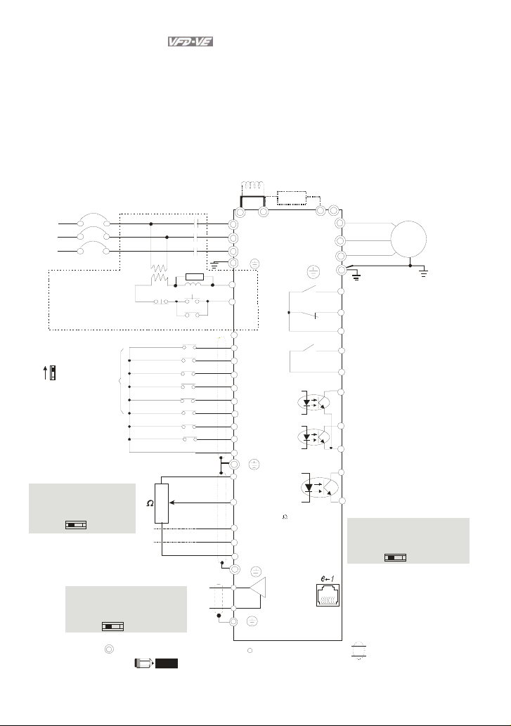
Figure 1 for models of VFD-VE Series (15 HP/11kW and below)
VFD007V 23A/43A -2, VFD015V 23A/43A-2 , VFD022V23 A/43A-2, V FD037V23A /43A-2,
VFD055V 23A/43A -2, VFD075V 23A/43A-2 , VFD110V43B-2, VFD110V23A/43A- 2
Fuse/NFB(No Fuse Breaker)
R(L1)
S(L2)
T(L3)
Recommended Circuit
when power supply
is turned OFF by a
fault output.
If the fault occurs, the
contact will be ON to turn
off the power and protect the power system.
Factory setting:
SINK Mode
Sink
Sw1
Source
Please refer to
Figure 3 for wiring
of S INK mo de an d
SOURCE mode.
ACI current/voltage selection
ACI Switch
Make sure that powe r is OFF
before changing the switch
setting.
0-20mA
Factory
setti ng
* Don't apply the mains voltage directly
to above terminals.
Analog Multi-function Output Terminal
AFM analog output selection
AFM Switch
Make sure that power is OFF
before changing the switch
setting.
0-10V
FWD/STOP
REV/STOP
Multi-s tep 1
Multi-step 2
Multi-step 3
Multi-s tep 4
No function
No function
Digital Signal Common
5K
0-10V
0-20mA
Main circuit (power) terminals
SA
ON
OFF
3
2
1
NOTE
The brake resistor is built-in to model VFD110V43B.
Jumpe r
MC
MC
DC choke
(optional)
Brake resistor
(optio nal)
+1
R(L1)
+2/B1
B2
S(L2)
T(L3 )
E
RB
RC
+24V
FWD
REV
MI1
MI2
MO1
MI3
MI4
MI5
MO2
MI6
DCM
E
+10V
Power supply
+10V 20mA
AVI
Master Frequency
0 to 10V 4 7k
ACI
4~20mA/0~10V
AUI
-10~+10V
ACM
Analog Signal Common
E
AFM
0~10VDC /2mA
ACM
Analog Signal common
E
Control circuit terminals
U(T1)
V(T2)
W(T3)
E
RA
Multi-function contact output 1
RB
(relay)
factory setting: fault indication
RC
MRA
Multi-function contact output 2
(relay)
48VDC 50mA
MRC
facto ry setting:
indicates that it is running
Multi-function contact output 3
(photocoupler)
Multi-function contact output 4
(photocoupler)
Multi-funct ion
Photocoupler Output
MCM
Digital Frequency Output
DFM
Te rm in al
fact ory setting: 1:1
Duty=50%, 10VDC
Digital Signal Common
DCM
DFM output signal selection
DFM Switch
Make sure that power is OFF
before changing the switch
setting.
RS-485 serial communication
1: +EV
2: GND
3: SG4: SG+
5: NC
6: NC
Motor
IM
3~
TP
OC
For communication,
it needs to use
VFD-USB01/IFD8500
to connect to PC.
Shielded leads & Cable
2-2 Revision August 2008, 03VE, SW V2.04
Page 26
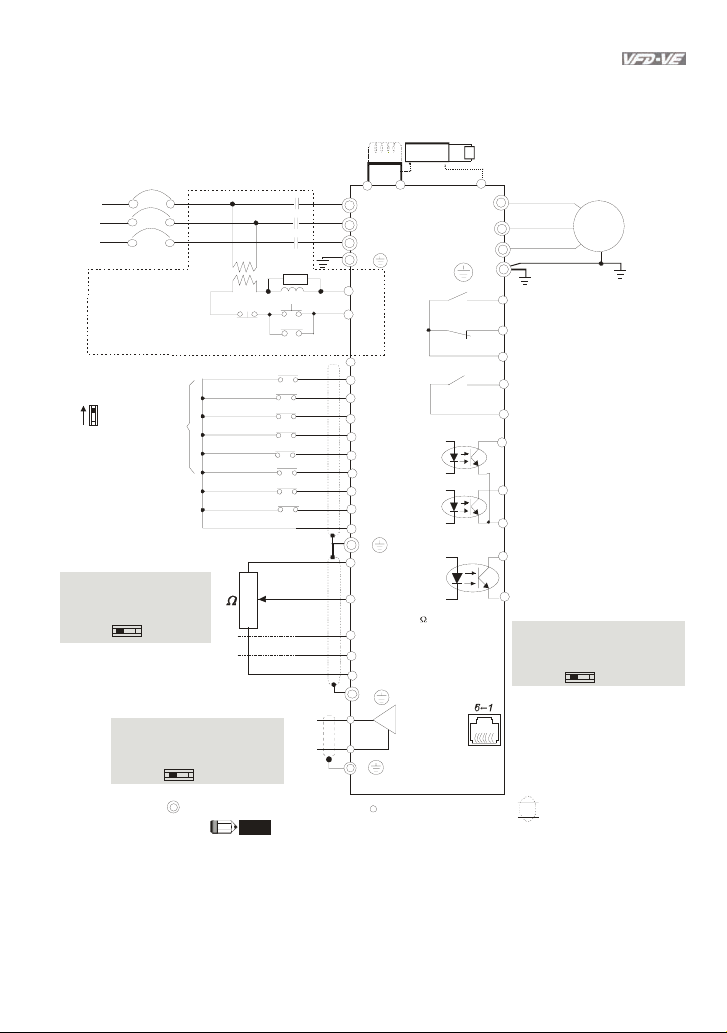
Figure 2 for models of VFD-VE Series (20HP/ 15kW and above)
VFD150V23A/43A-2, VFD185V23A /43A-2, VFD220 V23A/43 A-2, VFD300 V43A-2, VFD370 V43A-2,
VFD450V43A-2, V FD300V23 A-2, VFD370 V23A- 2, VFD550V43C -2, VFD750V43C-2
Fuse/NFB(No Fuse Breaker)
DC choke
(optional)
Jumper
R(L1)
S(L2)
MC
MC
AFM
ACM
Analog Signal common
T(L3)
E
RB
+10V
Power supply
+10V 20mA
Master Frequency
0 to 10V 4 7k
4~20mA/0~10V
AUI
-10~+10V
E
T(L3)
Recommended Circuit
wh en po wer s uppl y
is turned OFF by a
fault output.
If the fault occurs, the
contact will be ON to turn
off the power and protect the power system.
Factory setting:
SINK Mode
Sink
Sw1
Source
Please refer to
Figure 3 for wiring
of SIN K mo de and
SOURCEmod e.
ACI curre nt/volt age select ion
ACI Switch
Make sure that power is OFF
before changing the switch
setting.
0-20mA
Factory
setti ng
* Don't apply the mains voltage directly
to above terminals.
0-10V
Analog Multi-function Output Terminal
AFM analog output selection
AFM Switch
Make sure that power is OFF
before changing the switch
setting.
0-10V
OFF
FWD/STOP
REV/STO P
Multi-step 1
Multi-s tep 2
Multi-step 3
Multi-step 4
No function
No function
Digital Signal Common
5K
0-20mA
Main circuit (power) terminals
SA
ON
3
2
1
NOTE
The brake resistor is built-in to model VFD110V43B.
Chapter 2 Installation and Wiring|
brake unit
+1
R(L1)
S(L2)
(optional)
VFDB
+2
brake resistor
(optional)
-(minus sign)
U(T1)
V(T2)
W(T3)
E
RA
RC
+24V
FWD
REV
MI1
MI2
MO1
MI3
MI4
MI5
MO2
MI6
DCM
E
AVI
ACI
ACM
Analog Signal Common
E
0~10VDC/ 2mA
Control circuit terminals
Multi-function contact output 1
RB
(relay)
facto ry setting: fault in dication
RC
MRA
Multi-function contact output 2
(re lay)
48VDC 50mA
MRC
facto ry setting:
indicates that it is running
Multi-function contact output 3
(photocoupler)
Multi-function contact output 4
(photocoupler)
Multi-function
Photocoupler Output
MCM
Digital Frequency Output
DFM
Terminal
factory setting: 1:1
Duty=50%, 10VDC
Digital Signal Common
DCM
DFM output signal selection
DFM Switch
Make sure that power is OFF
before changing the switch
setting.
OC
RS-485 serial communication
1: +EV
2: GND
3: SG4: SG+
5: NC
6: NC
Shielded leads & Cable
Motor
IM
3~
TP
For communication,
it needs to use
VFD-USB01/IFD 8500
to connect to PC.
Revision August 2008, 03VE, SW V2.04 2-3
Page 27
Chapter 2 Installation and Wiring|
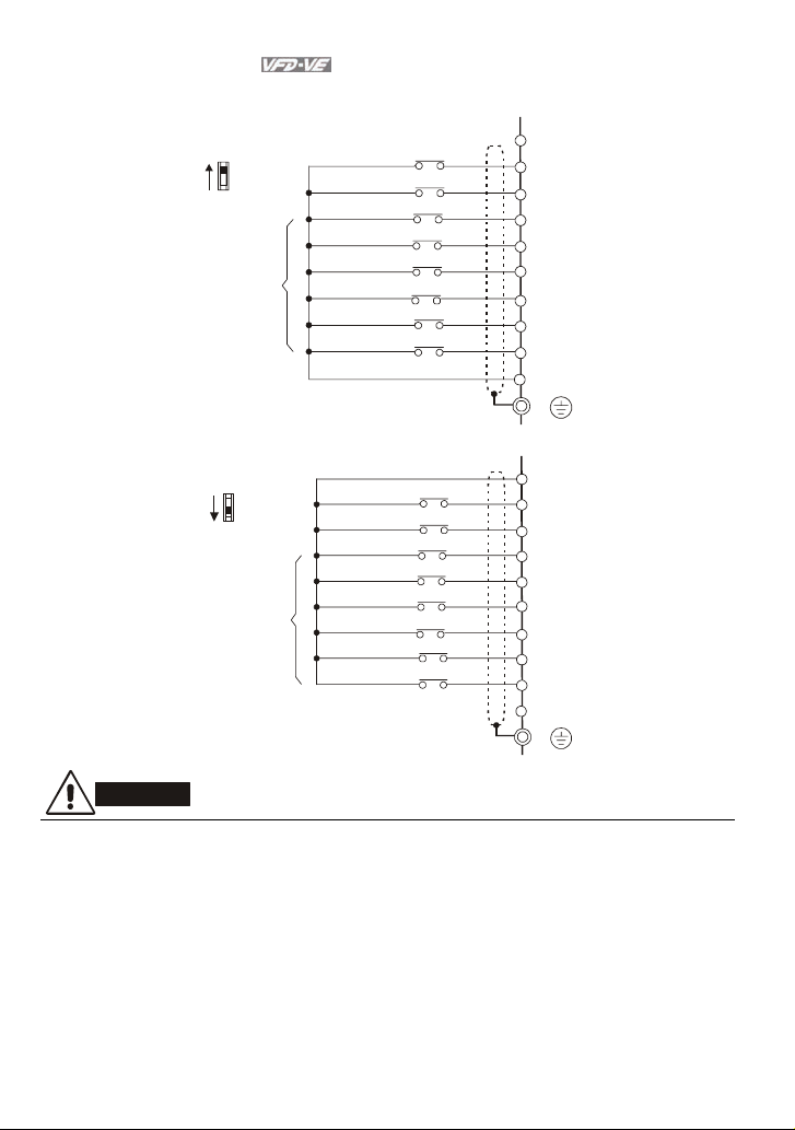
Figure 3 Wiring for SINK(NPN) mode and SOURCE(PNP) mode
SINK/NPN Mode
Sink
SW1
Source
Factor y
setting
*Don't apply the mains voltage directly
to above terminals.
FWD/STOP
REV/STOP
Multi-step1
Multi-step2
Multi-step3
Multi-step4
No Function
No Function
Digital Signal Common
SOURCE/PNP Mode
Sink
SW1
Source
Factory
setting
*Don't apply the mains voltage directly
to above terminals.
FWD/STOP
REV/STOP
Multi-step1
Multi-step2
Multi-step3
Multi-step4
No Function
No Function
+24V
FWD
REV
MI1
MI2
MI3
MI4
MI5
MI6
DCM
E
+24V
FWD
REV
MI1
MI2
MI3
MI4
MI5
MI6
DCM
E
CAUTION!
1. The wiring of main circuit and control circuit should be separated to prevent erroneous actions.
2. Please use shield wire for the control wiring and not to expose the peeled-off net in front of the
terminal.
3. Please use the shield wire or tube for the power wiring and ground the two ends of the shield
wire or tube.
2.2 External Wiring
2-4 Revision August 2008, 03VE, SW V2.04
Page 28
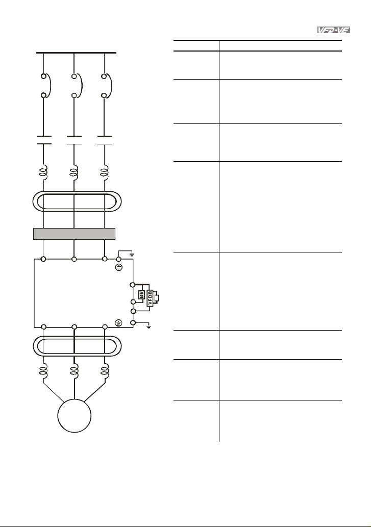
Power Suppl
y
EMI Filter
R/L1
S/L2
U/T1 V/T2
T/L3
W/T3
FUSE/NFB
Magnetic
cont actor
Input AC
Line React or
Zero-phase
Reac tor
Break resistor
+/B1
B2
-
E
Zero-phase
Reactor
Outpu t AC
Line React or
(optional)
Break unit ( optional)
Break resist or
(option al)
BR
Chapter 2 Installation and Wiring|
Items Explanations
Power
supply
Please follow the specific power
supply requirements shown in
Appendix A.
There may be an inrush current
Fuse/NFB
(Optional)
during power up. Please check the
chart of Appendix B and select the
correct fuse with rated current. Use of
an NFB is optional.
Magnetic
contactor
(Optional)
Please do not use a Magnetic
contactor as the I/O switch of the AC
motor drive, as it will reduce the
operating life cycle of the AC drive.
Used to improve the input power
factor, to reduce harmonics and
provide protection from AC line
disturbances (surges, switching
Input AC
Line Reactor
(Optional)
spikes, short interruptions, etc.). AC
line reactor should be installed when
the power supply capacity is 500kVA
or more or advanced capacity is
activated .The wiring distance should
be
10m. Refer to appendix B for
≤
details.
Zero phase reactors are used to
Zero-phase
Reactor
(Ferrite Core
Common
Choke)
(Optional)
reduce radio noise especially when
audio equipment is installed near the
inverter. Effective for noise reduction
on both the input and output sides.
Attenuation quality is good for a wide
range from AM band to 10MHz.
Appendix B specifies the zero phase
reactor. (RF220X00A)
EMI filter
(Optional)
Brake
Resistor
(Optional)
To reduce electromagnetic
interference, please refer to Appendix
B for more details.
Used to reduce the deceleration time
of the motor. Please refer to the chart
in Appendix B for specific Brake
Resistors.
Motor
Output AC
Line Reactor
(Optional)
Motor surge voltage amplitude
depends on motor cable length. For
applications with long motor cable
(>20m), it is necessary to install a
2.3 Main Circuit
2.3.1 Main Circuit Connection
Revision August 2008, 03VE, SW V2.04 2-5
Page 29
Chapter 2 Installation and Wiring|
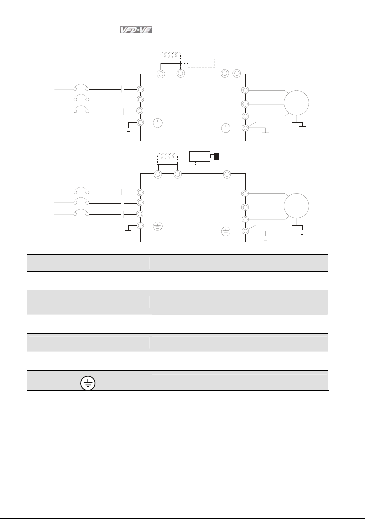
Figure 1 for the main terminals
No-fuse breaker
( NFB )
R
S
T
Figure 2 for the main terminals
No-fuse breaker
( NFB )
R
S
T
Terminal Symbol Explanation of Terminal Function
R/L1, S/L2, T/L3 AC line input terminals (1-phase/3-phase)
U/T1, V/T2, W/T3
+1, +2 Connections for DC Choke (optional)
MC
MC
Br ake r es ist o r(O pti ona l)
-
VFDB
B2
U(T1)
V(T2)
W(T3)
E
Br ake r es ist or
(optional)
-
U(T1)
V(T2)
W(T3)
E
+1 +2/B1
R(L1)
S(L2)
T(L3)
E
+1
R(L1)
S(L2)
T(L3)
E
+2
AC drive output terminals for connecting 3-phase
induction motor
Motor
IM
3~
Motor
IM
3~
+2/B1, B2 Connections for Brake Resistor (optional)
+2~(-), +2/B1~(-) Connections for External Brake Unit (VFDB series)
2-6 Revision August 2008, 03VE, SW V2.04
Earth connection, please comply with local regulations.
Page 30
Mains power terminals (R/L1, S/L2, T/L3)
Connect these terminals (R/L1, S/L2, T/L3) via a no-fuse breaker or earth leakage
breaker to 3-phase AC power (some models to 1-phase AC power) for circuit protection. It
is unnecessary to consider phase-sequence.
It is recommended to add a magnetic contactor (MC) in the power input wiring to cut off
power quickly and reduce malfunction when activating the protection function of AC motor
drives. Both ends of the MC should have an R-C surge absorber.
Please make sure to fasten the screw of the main circuit terminals to prevent sparks
which is made by the loose screws due to vibration.
Please use voltage and current within the regulation shown in Appendix A.
When using leakage-current breaker to prevent leakage current,
Do NOT run/stop AC motor drives by turning the power ON/OFF. Run/stop AC motor
drives by RUN/STOP command via control terminals or keypad. If you still need to
run/stop AC drives by turning power ON/OFF, it is recommended to do so only ONCE per
hour.
Do NOT connect 3-phase models to a 1-phase power source.
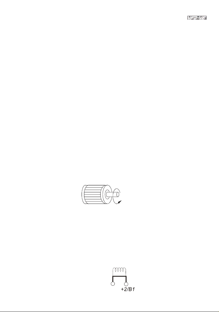
Output terminals for main circuit (U, V, W)
When the AC drive output terminals U/T1, V/T2, and W/T3 are connected to the motor
terminals U/T1, V/T2, and W/T3, respectively, the motor will rotate counterclockwise (as
viewed on the shaft end of the motor) when a forward operation command is received. To
permanently reverse the direction of motor rotation, switch over any of the two motor
leads.
Chapter 2 Installation and Wiring|
Forward
running
DO NOT connect phase-compensation capacitors or surge absorbers at the output
terminals of AC motor drives.
With long motor cables, high capacitive switching current peaks can cause over-current,
high leakage current or lower current readout accuracy. To prevent this, the motor cable
should be less than 20m for 3.7kW models and below. And the cable should be less than
50m for 5.5kW models and above. For longer motor cables use an AC output reactor.
Use well-insulated motor, suitable for inverter operation.
Terminals [+1, +2] for connecting DC reactor
DC reactor
Jumper
+1
Revision August 2008, 03VE, SW V2.04 2-7
Page 31

Chapter 2 Installation and Wiring|
1
1
)
To improve power factor and reduce harmonics connect a DC reactor between terminals
[+1, +2]. Please remove the jumper before connecting the DC reactor.
NOTE
Models of 15kW and above have a built-in DC reactor.
Terminals [+2/B1, B2] for connecting brake resistor and terminals [+1, +2/B1] for
connecting external brake unit
BR
VFDB
BR
+2/B
Connect a brake resistor or brake unit in applications with frequent deceleration ramps,
B2
+2/B
Brake resistor(optional
Brake unit(optional)
Refe r to App endix B fo r the use of
sp ecia l br aki ng r esis tor /uni t
-
short deceleration time, too low brake torque or requiring increased brake torque.
If the AC motor drive has a built-in brake chopper (all models of 11kW and below),
connect the external brake resistor to the terminals [+2/B1, B2].
Models of 15kW and above don’t have a built-in brake chopper. Please connect an
external optional brake unit (VFDB-series) and brake resistor. Refer to VFDB series user
manual for details.
Connect the terminals [+(P), -(N)] of the brake unit to the AC motor drive terminals
[+2(+2/B1), (-)]. The length of wiring should be less than 5m with twisted cable.
When not used, please leave the terminals [+2/B1, -] open.
WARNING!
1. Short-circuiting [B2] or [-] to [+2/B1] can damage the AC motor drive.
Grounding terminals (
Make sure that the leads are connected correctly and the AC drive is properly grounded.
)
(Ground resistance should not exceed 0.1Ω.)
Use ground leads that comply with local regulations and keep them as short as possible.
Multiple VFD-VE units can be installed in one location. All the units should be grounded
directly to a common ground terminal, as shown in the figure below. Ensure there are no
ground loops.
goodexcellent
2-8 Revision August 2008, 03VE, SW V2.04
not allowed
Page 32

2.3.2 Main Circuit Terminals
Frame B
+2
+1
R/L1 S/L2 T/L3
U/T1 V/T2 W/T3
B2
-
1
B
Screw Torque :
18Kgf-cm
Wire Gauge :
18~10AWG
Chapter 2 Installation and Wiring|
Main circuit terminals
R/L1, S/L2, T/L3, U/T1, V/T2, W/T3,
, +1, +2/B1, -, B2
Models Wire Torque Wire Type
VFD007V23A-2
VFD007V43A-2
VFD015V23A-2
VFD015V43A-2
VFD022V23A-2
14-10 AWG
(2.1-5.3mm
2
)
18kgf-cm
(15.6in-lbf)
VFD022V43A-2
VFD037V23A-2
VFD037V43A-2
Stranded
copper only,
o
C
75
Frame C
Main circuit terminals
R/L1, S/L2, T/L3, U/T1, V/T2, W/T3,
, +1, +2/B1, -, B2
Models Wire Torque Wire Type
VFD055V23A-2
POWER
VFD075V23A-2
VFD110V43B-2
12-8 AWG
(3.3-8.4mm
VFD055V43A-2
VFD075V43A-2
IM
MOTOR3
2
)
30kgf-cm
(26in-lbf)
Stranded
copper only,
o
75
C
Revision August 2008, 03VE, SW V2.04 2-9
Page 33

Chapter 2 Installation and Wiring|
Frame D
W/T3
R/L1
S/L2 T/L3
POWER
V/T2
+2+1
-
IM
( )
( )
-
DC DC
MOTOR
+
3
Frame E
POWER
ALARM
Main circuit terminals
R/L1, S/L2, T/L3, U/T1, V/T2, W/T3,
Models Wire Torque Wire Type
VFD110V23A-2
VFD110V43A-2
VFD150V43A-2
VFD150V23A-2
VFD185V23A-2
8-2 AWG
(8.4-33.6mm
2
)
30kgf-cm
(26in-lbf)
VFD185V43A-2
VFD220V43A-2
VFD220V23A-2
Main circuit terminals
R/L1, S/L2, T/L3, U/T1, V/T2, W/T3,
Models Wire Torque Wire Type
, +1, +2, -
copper only,
, +1, +2, -
Stranded
o
75
C
CHARGE
W/T3S/L2R/L1 T/L3 +2+1 U /T1 V/T2
Screw Torque:
POWER
NOTE
#
To connect 6 AWG (13.3 mm2) wires, use Recognized Ring Terminals
IM
MOTOR
(173in-lbf)
3
200kgf-cm
VFD300V43A-2
VFD370V43A-2
VFD450V43A-2
VFD300V23A-2
VFD370V23A-2
VFD550V43C-2
VFD750V43C-2
4-2 AWG
(21.2-33.6mm
2
)
57kgf-cm
(49in-lbf)
200kgf-cm
(173in-lbf)
Stranded
copper
only, 75
o
C
2.4 Control Terminals
Circuit diagram for digital inputs (SINK current 16mA.)
2-10 Revision August 2008, 03VE, SW V2.04
Page 34

SINK Mode
+24
Chapter 2 Installation and Wiring|
SOURCE Mode
DCM
multi-input
terminal
MRA
MRC
Internal CircuitDCM
The Position of the Control Terminals
RA
RC
MCM
+24V
FWD
MI1
RB
DCM
MO1 MO2
REV
MI2
Multi-Input
Term inal
+10V
MI3
MI5
MI4
MI6
+24V
DFM
Internal Circuit
AUI
AFM
AVI
ACI
ACM
Revision August 2008, 03VE, SW V2.04 2-11
Page 35

Chapter 2 Installation and Wiring|
Terminal symbols and functions
Terminal
Symbol
Terminal Function
FWD Forward-Stop Command
REV Reverse-Stop Command
ON: Run in FWD direction
OFF: Stop acc. to Stop Method
ON: Run in REV direction
OFF: Stop acc. to Stop Method
Factory Settings (SINK)
ON: Connect to DCM
+24V DC Voltage Source +24VDC, 80mA, used for SOURCE mode.
MI1 Multi-function Input 1
MI2 Multi-function Input 2
MI3 Multi-function Input 3
MI4 Multi-function Input 4
Refer to Pr.02-01 to Pr.02-06 for programming
the Multi-function Inputs.
ON: the activation current is 6.5mA. OFF:
leakage current tolerance is 10μA.
MI5 Multi-function Input 5
MI6 Multi-function Input 6
Digital Frequency Meter
(Open Collector Output)
DFM-DCM
DFM
Max: 48V
J5
50mA
50%
Pulse voltage output monitor signal,
proportional to output frequency
Duty-cycle: 50%
Ratio: Pr.02-18
Min. load: 4.7kΩ
Max. current: 50mA
internal circuit
100%
DCM Digital Signal Common
Max. voltage: 48Vdc
Jumper: DFM jumper, factory
setting is OC
Common for digital inputs and used for SINK
mode.
Multi-function Relay Output 1
RA
(N.O.) a
Resistive Load:
5A(N.O.)/3A(N.C.) 240VAC
Multi-function Relay Output 1
RB
(N.C.) b
RC Multi-function Relay Common
MRA
Multi-function Relay Output 2
(N.O.) a
5A(N.O.)/3A(N.C.) 24VDC
Inductive Load:
1.5A(N.O.)/0.5A(N.C.) 240VAC
1.5A(N.O.)/0.5A(N.C.) 24VDC
To output monitor signal, including in operation,
frequency arrival, overload and etc.
Refer to Pr.02-11~02-12 for programming
MRC Multi-function Relay Common
2-12 Revision August 2008, 03VE, SW V2.04
Page 36

Chapter 2 Installation and Wiring|
Terminal
Symbol
Terminal Function
Factory Settings (SINK)
ON: Connect to DCM
+10V Potentiometer Power Supply +10VDC 20mA (variable resistor 3-5kohm)
Multi-function Output
MCM
Common (Photocoupler)
Multi-function Output 1
MO1
(Photocoupler)
Multi-function Output 2
MO2
(Photocoupler)
Max. 48VDC 50mA
Maximum 48VDC, 50mA
Refer to Pr.02-13 to Pr.02-14 for programming
MCM
Max: 48Vdc
50mA
MO1~MO2-DCM
MO1~MO2
Internal Circuit
Analog voltage Input
AVI
+10V
AVI
AVI cir cuit
Impedance: 200kΩ
Resolution: 12 bits
Range: 0 ~ 10VDC = 0 ~ Max. Output
Frequency (Pr.01-00)
Set-up: Pr.03-00 ~ Pr.03-02
Analog current Input
ACI
ACM
ACI
internal circuit
ACI circuit
Impedance: 250Ω
Resolution: 12 bits
Range: 4 ~ 20mA/0~10V =
0 ~ Max. Output Frequency
(Pr.01-00)
Set-up: Pr.03-00 ~ Pr.03-02
ACM
Auxiliary analog voltage input
+10
~
-10V
AUI
AUI
ACM
internal circuit
AUI circuit
internal circuit
Jumper: ACI jumper, factory setting is
4-20mA
Impedance: 200kΩ
Resolution: 12 bits
Range: -10 ~ +10VDC =
0 ~ Max. Output Frequency
(Pr.01-00)
Set-up: Pr.03-00 ~ Pr.03-02
Revision August 2008, 03VE, SW V2.04 2-13
Page 37

Chapter 2 Installation and Wiring|
AFMA
Terminal
Symbol
Terminal Function
Analog output meter
Impedance: 18.5kΩ (voltage output)
Factory Settings (SINK)
ON: Connect to DCM
1.1mΩ (current output)
Output current 20m A max
Resolution: max. frequency corresponds to
AFM
0-10V
Range: 0 ~ 10V/0 ~ 20mA
Function: Pr.03-18
0~20mA
Switch: AFM switch, factory setting is 0-
10V
Common for AVI, ACI, AUI, AFM
ACM
CM
Analog control signal
(common)
*Control signal wiring size: 18 AWG (0.75 mm2) with shielded wire.
Analog input terminals (AVI, ACI, AUI, ACM)
Analog input signals are easily affected by external noise. Use shielded wiring and keep it
as short as possible (<20m) with proper grounding. If the noise is inductive, connecting
the shield to terminal ACM can bring improvement.
If the analog input signals are affected by noise from the AC motor drive, please connect
a capacitor and ferrite core as indicated in the following diagrams:
C
ferrite core
AVI/ACI/AUI
ACM
wind each wires 3 times or more around the core
Digital inputs (FWD, REV, MI1~MI6, DCM)
When using contacts or switches to control the digital inputs, please use high quality
components to avoid contact bounce.
Digital outputs (MO1, MO2, MCM)
Make sure to connect the digital outputs to the right polarity, see wiring diagrams.
When connecting a relay to the digital outputs, connect a surge absorber or fly-back diode
across the coil and check the polarity.
2-14 Revision August 2008, 03VE, SW V2.04
Page 38

General
Keep control wiring as far as possible from the power wiring and in separate conduits to
avoid interference. If necessary let them cross only at 90º angle.
The AC motor drive control wiring should be properly installed and not touch any live
power wiring or terminals.
NOTE
If a filter is required for reducing EMI (Electro Magnetic Interference), install it as close as
possible to AC drive. EMI can also be reduced by lowering the Carrier Frequency.
When using a GFCI (Ground Fault Circuit Interrupter), select a current sensor with
sensitivity of 200mA, and not less than 0.1-second detection time to avoid nuisance
tripping.
Chapter 2 Installation and Wiring|
DANGER!
Damaged insulation of wiring may cause personal injury or damage to circuits/equipment if it comes
in contact with high voltage.
The specification for the control terminals
MRA
MRC
The Position of the Control Terminals
RA
RC
MCM
RB
MO1 MO2
+24V
DCM
FWD
REV
MI1
MI2
+1 0V
MI3
MI5
MI4
MI6
DFM
AFM
AUI
AVI
ACI
ACM
Frame Torque Wire
B, C, D, E, E1 8 kgf-cm (6.9 in-lbf) 22-14 AWG (0.3-2.1mm2)
NOTE
Frame B: VFD007V23A/43A-2, VFD015V23A/43A-2, VFD022V23A/43A-2, VFD037V23A/43A-2;
Frame C: VFD055V23A/43A-2, VFD075V23A/43A-2, VFD110V43B-2,
Frame D: VFD110V23A/43A-2, VFD150V23A/43A-2, VFD185V23A/43A-2, VFD220V23A/43A-2
Frame E: VFD300V43A-2, VFD370V43A-2, VFD450V43A-2
Frame E1: VFD300V23A-2, VFD370V23A-2, VFD550V43C-2, VFD750V43C-2
Revision August 2008, 03VE, SW V2.04 2-15
Page 39

Page 40

Chapter 3 Digital Keypad Operation and Start Up
3.1 Digital Keypad KPV-CE01
3.1.1 Description of the Digital Keypad KPV-CE01
F
H
U
MODE Selection Key
Press this key to view different
operating values
moves cursor to the left
FWD/REV Direction Key
Display Message Descriptions
Left Key
RUN key
JOG
RUN
Displays the AC drive Master Frequency.
Displays the actual output frequency present at terminals U/T1, V/T2, and
W/T3.
User defined unit (where U = F x Pr.00-05)
Displays the output current present at terminals U/T1, V/T2, and W/T3.
KPV-CE01
EXTPU
PU
STOP
RESET
LED Display
Display frequency, current, voltage
and error, etc.
Part Number
Status Display
Display of driver status
Right Key
Moves the cursor right
STOP/RESET
The counter value (C).
Revision August 2008, 03VE, SW V2.04 3-1
Page 41

Chapter 3 Digital Keypad Operation and Start Up|
Display Message Descriptions
Displays the selected parameter.
Displays the actual stored value of the selected parameter.
External Fault.
Display “End” for approximately 1 second if input has been accepted by
pressing
key. After a parameter value has been set, the new
value is automatically stored in memory. To modify an entry, use the
, and keys.
Display “Err”, if the input is invalid.
3-2 Revision August 2008, 03VE, SW V2.04
Page 42

Chapter 3 Digital Keypad Operation and Start Up|
3.1.2 How to Operate the Digital Keypad KPV-CE01
Selection mode
START
F
H
U
F
H
U
F
H
U
MODE
NOTE: In the selection mode, press
To set pa rame ter s
NOTE: In the parameter setting mode, you can press
To shift cursor
START
F
H
U
To modify data
START
F
H
U
MODE
F
H
U
MODE
to set the parameters.
F
H
U
MODE
F
H
U
F
H
U
F
H
U
move to previous display
MODE
F
H
U
F
H
U
F
H
U
F
H
U
parameter set successfully
F
H
U
parameter set error
to return to the selection mode.
F
H
U
F
H
U
F
H
U
MODEMODE
GO START
To switch display mode
F
H
U
START
MODE
F
H
U
F
H
U
MODE
F
H
U
F
H
U
F
H
U
F
H
U
F
H
U
F
H
U
F
H
U
Revision August 2008, 03VE, SW V2.04 3-3
Page 43

Chapter 3 Digital Keypad Operation and Start Up|
To copy parameters 1
Copy parameters from the AC Motor Drive to the KPV-CE01
F
H
U
F
H
U
F
H
U
F
H
U
F
H
U
F
H
U
F
H
U
start blinking
F
H
U
F
H
U
It will display "End" to indicate that
the first parameter is saved, then
return to "rEAd0".
F
H
U
F
H
U
F
H
U
F
H
U
F
H
U
start blinking
about 2-3 seconds
To copy parameters 2
Copy parameters from to the KPV-CE01 the AC Motor Drive
F
H
U
F
H
U
about 2-3 seconds
F
H
U
F
H
U
F
H
U
F
H
U
F
H
U
start blinking
F
H
U
F
H
U
F
H
U
It will display "End" to indicate that
the first parameter is saved, then
return to "SAvEv".
F
H
U
F
H
U
start blinking
about 2-3 seconds
about 2-3 seconds
F
H
U
F
H
U
It will display "End" to indicate that
the second parameter is saved, then
return to "rEAd1".
F
H
U
F
H
U
F
H
U
F
H
U
It will display "End" to indicate that
the second parameter is saved, then
return to "SAvEv".
F
H
U
F
H
U
F
H
U
F
H
U
F
H
U
F
H
U
3-4 Revision August 2008, 03VE, SW V2.04
Page 44

Chapter 3 Digital Keypad Operation and Start Up|
3.1.3 Dimension of the Digital Keypad
F
H
U
RUN
JOG
STOPJOG
MODE
FWD
KPV-CEO1
REVEXTPU
PU
Unit: mm [inch]
FWD
REV
RUN
STOP
RESET
PROG
DATA
LABEL 1
3.1.4 Reference Table for the LCD Display of the Digital Keypad
Digital 0 1 2 3 4 5 6 7 8 9
LCD
English
alphabet
LCD
English
alphabet
LCD
English
alphabet
LCD
A b Cc d E F G Hh I Jj
K L n Oo P q r S Tt U
v Y Z
Revision August 2008, 03VE, SW V2.04 3-5
Page 45

Chapter 3 Digital Keypad Operation and Start Up|
3.1.5 Operation Method
Refer to 3.1.2 How to operate the digital keypad KPV-CE01 and chapter 4 parameters for
setting. Please choose a suitable method depending on application and operation rule. The
operation is usually used as shown in the following table.
Operation Method Frequency Source
KPV-CE01 keypad
FWD/STOP
REV/STOP
Multi-step 1
Multi-step 2
Multi-step 3
Multi-step 4
No function
No function
Digital Signal Common
5K
0-20mA
Control circuit terminals
Operate from
external signal
Factory setting:
SINK Mode
Sink
Sw1
Source
Please refer to
Figure 3 for wiring
of SIN K mode and
SOURCEmode.
ACI current /voltage selectio n
ACI Switch
Make sure that power is OFF
before c hanging the switch
setting.
0-20mA
Main c ircuit (po wer) t ermin als
Factory
setti ng
* Don't apply the mains voltage directly
to abov e te rmin als .
0-10V
Analog Multi-function Output Terminal
AFM analog output selection
AFM Switch
Make sure that power is OFF
before c hanging the switch
setti ng.
0-10V
3
2
1
Operation Command
RUN
+24V
FWD
REV
MI1
MI2
MI3
MI4
MI5
MI6
DCM
E
+10V
Power supply
+10V 20mA
AVI
Master Fr equency
0 to 10V 4 7k
ACI
4~20mA/0~10V
AUI
-10~+ 10V
ACM
Analog Signal Common
E
AFM
ACM
Analog S ignal common
E
Shielded leads & Cable
Source
STOP
RESET
0~10VDC /2mA
Operate from
communication
Please refer to the communication address 2000H and 2119H settings in the
communication address definition.
3.2 Start-up
3.2.1 Preparations before Start-up
3-6 Revision August 2008, 03VE, SW V2.04
Page 46

Carefully check the following items before proceeding.
Make sure that the wiring is correct. In particular, check that the output terminals U, V, W.
Chapter 3 Digital Keypad Operation and Start Up|
are NOT connected to power and that the drive is well grounded.
Verify that there are no short-circuits between terminals and from terminals to ground or
mains power.
Check for loose terminals, connectors or screws.
Verify that no other equipment is connected to the AC motor
Make sure that all switches are OFF before applying power to ensure that the AC motor
drive doesn’t start running and there is no abnormal operation after applying power.
Make sure that the front cover is well installed before applying power.
Do NOT operate the AC motor drive with humid hands.
The keypad shows briefly "Delta" and then should light up as follows (normal status with
no error)
F
H
U
KPV-CE01
EXT P U
JOG
RUN
PU
STOP
RESET
- If the drive has built-in fan (2hp/1.5kW and above) it should run. The factory setting
of Fan Control Pr.07-19=00 (Fan always on).
Revision August 2008, 03VE, SW V2.04 3-7
Page 47

Chapter 3 Digital Keypad Operation and Start Up|
3.2.2 Trial Run
After finishing checking the items in “3.2.1 preparation before start-up”, you can perform a
trial run. The factory setting of operation source is from keypad (Pr.00-20=00).
1. After applying power, verify that LED “F”
F
is on and the display shows 60.00Hz.
2. Setting frequency to about 5Hz by using
key.
3. Pressing
RUN
key for forward running.
And if you want to change to reverse
running, you should press
key. The
LED will display the status. And if you
want to decelerate to stop, please press
STOP
RESET
key.
4. Check following items:
Check if the motor direction of rotation
is correct.
Check if the motor runs steadily
without abnormal noise and vibration.
Check if acceleration and deceleration
are smooth.
If the results of trial run are normal, please
start formal run.
STOP
STOP
STOP
KPV-CE01
JOG
FWD
REV EXT PU
RUN
F
KPV-CE01
JOG
FWD
REV EXT PU
RUN
F
KPV-CE01
JOG
FWD
REV EXT PU
RUN
RUN
F
RUN
F
RUN
STOP
STOP
STOP
KPV-CE01
JOG
FWD
REV EXT PU
KPV-CE01
JOG
FWD
REV EXT PU
KPV-CE01
JOG
FWD
REV EXT PU
F
F
RUN
STOP
KPV-CE01
JOG
FWD
REV EXT PU
RUN
F
RUN
STOP
STOP
KPV-CE01
JOG
FWD
REV EXT PU
RUN
KPV-CE01
JOG
FWD
REV EXT PU
RUN
F
RUN
F
STOP
STOP
STOP
KPV-CE01
JOG
FWD
REV EXT PU
KPV-CE01
JOG
FWD
REV EXT PU
KPV-CE01
JOG
FWD
REV EXT PU
PU
RUN
STOP
KPV-CE01
JOG
FWD
REV EXT PU
RUN
STOP JOG
FWD
KPV-CE01
REV EXT
PU
RUN
3-8 Revision August 2008, 03VE, SW V2.04
Page 48

NOTE
1. Please stop running immediately if any fault occurs and refer to troubleshooting for solving the
problem.
2. Please do NOT touch output terminals U, V, W when power is still applied to L1/R, L2/S, L3/T
even when the AC motor drive has stopped. The DC-link capacitors may still be charged to
hazardous voltage levels, even if the power has been turned off.
3. To avoid damage to components, do not touch them or the circuit boards with metal objects or
your bare hands.
Chapter 3 Digital Keypad Operation and Start Up|
Revision August 2008, 03VE, SW V2.04 3-9
Page 49

Chapter 3 Digital Keypad Operation and Start Up|
This page intentionally left blank.
3-10 Revision August 2008, 03VE, SW V2.04
Page 50

Chapter 4 Parameters
The VFD-VE parameters are divided into 12 groups by property for easy setting. In most applications,
the user can finish all parameter settings before start-up without the need for re-adjustment during
operation.
The 12 groups are as follows:
Group 0: System Parameters
Group 1: Basic Parameters
Group 2: Digital Input/Output Parameters
Group 3: Analog Input/Output Parameters
Group 4: Multi-Step Speed Parameters
Group 5: Motor Parameters
Group 6: Protection Parameters
Group 7: Special Parameters
Group 8: High-function PID Parameters
Group 9: Communication Parameters
Group 10: Speed Feedback Control Parameters
Group 11: Advanced Parameters
Revision August 2008, 03VE, SW V2.04 4-1
Page 51

Chapter 4 Parameters|
4.1 Summary of Parameter Settings
: The parameter can be set during operation.
Group 0 System Parameters
Pr. Explanation Settings
Identity Code of the AC
00-00
motor drive
Rated Current Display of
00-01
the AC motor drive
Parameter Reset
00-02
Start-up Display Selection
00-03
Content of Multi Function
00-04
Display
User-Defined Coefficient K
00-05
00-06 Software Version Read-only
Password Input
00-07
Password Set
00-08
Energy Saving Gain
00-09
Control Method
00-10
V/f Curve Selection
00-11
Constant/Variable Torque
00-12
Selection
Optimal
Acceleration/Deceleration
00-13
Setting
0
Read-only
Read-only 0
0: No function
1: Read only
2: Enable group 11 parameters setting
8: Keypad lock
9: All parameters are reset to factor y settings (50Hz,
220V/380V)
10: All parameters are reset to factor y settings (60Hz,
220V/440V)
0: Display the frequency command va lue (LED F)
1: Display the actual output frequenc y (LED H)
2: Multifunction display, see Pr.00- 04 (LED U)
3: Display the output current (A)
0: Display output current (A)
1: Display counter value (C)
2: Display output frequency (H)
3: Display DC-BUS voltage (
4: Display output voltage (E)
5: Output power factor angle (n)
6: Display output power (kW)
7: Display actual motor speed (HU)
8: Display estimate output torque (kg-m )
9: Display PG position (G) (r efer to Pr.10-00 and Pr.10-
01)
10: Display PID feedback
11: Display AVI (%)
12: Display ACI (%)
13: Display AUI (%)
14: Display the temperature of heat sink (°C)
15: Display the temperature of IGBT (°C)
16: The status of digital input (ON/OFF)
17: The status of digital output (ON/OFF )
18: Multi-step speed
19: The corresponding CPU pin status of digital input
20: The corresponding CPU pin status of digital output
21: Number of actual motor revolution (PG1 of PG card)
22: Pulse input frequency (PG2 of PG c ard)
23: Pulse input position (PG2 of PG card)
Digit 4: decimal point number (0 to 3)
Digit 0-3: 40 to 9999
1 to 9998 and 10000 to 65535
0 to 2: times of wrong password
1 to 9998 and 10000 to 65535
0: No password set or successful input i n Pr.00-07
1: Password has been set
10~1000 % 100%
0: V/f Control
1: V/f Control + Encoder (VFPG)
2: Sensorless vector control (SVC)
3: FOC vector control + Encoder (FOCPG )
4: Torque control + Encoder (T QRPG)
0: V/f curve determined by group 01
1: 1.5 power curve
2: Square curve
0: Constant Torque (100%)
1: Variable Torque (125%)
0: Linear accel./decel. I
1: Auto accel., linear decel.
2: Linear accel., auto decel.
3: Auto accel./decel.
Factory
VF VFPG SVC FOCPG TQRPG
Setting
○ ○ ○ ○ ○
○ ○ ○ ○ ○
0
○ ○ ○ ○ ○
0
○ ○ ○ ○ ○
0
○ ○ ○ ○ ○
u
)
0
○ ○ ○ ○ ○
#.#
○ ○ ○ ○ ○
0
○ ○ ○ ○ ○
0
○ ○ ○ ○ ○
0
○ ○ ○ ○ ○
0
○ ○
0
○ ○ ○ ○
0
○ ○ ○ ○
○
4-2 Revision August 2008, 03VE, SW V2.04
Page 52

Pr. Explanation Settings
Time Unit for
Acceleration/Deceleration
00-14
and S Curve
00-15 Reserved
00-16 Reserved
Carrier Frequency
00-17
Auto Voltage Regulation
00-18
(AVR) Function
Auto Energy-saving
00-19
Operation
Source of the Master
00-20
Frequency Command
Source of the Operation
00-21
Command
Stop Method
00-22
Reverse Operation
00-23
4: Stall prevention by auto accel./decel. (lim ited by 01-12
to 01-21)
0: Unit: 0.01 second
1: Unit: 0.1 second
1~15KHz 10
0: Enable AVR
1: Disable AVR
2: Disable AVR when deceleration stop
0: Disable
1: Enable
0: Digital keypad (KPV-CE01)
1: RS-485 serial communication
2: External analog input (Pr. 03-00)
3: External UP/DOWN terminal
4: Pulse input without direction command (Pr.10-15
without direction)
5: Pulse input with direction command (Pr.10-15)
0: Digital keypad (KPV-CE01)
1: External terminals. Keypad STO P disabled.
2: RS-485 serial communication (RJ- 11). Keypad STOP
disabled.
0: Ramp to stop
1: Coast to stop
0: Enable reverse
1: Disable reverse
2: Disable forward
Chapter 4 Parameters|
Factory
VF VFPG SVC FOCPG TQRPG
Setting
0
○ ○ ○ ○
○ ○ ○ ○ ○
0
○ ○ ○ ○ ○
0
○ ○ ○ ○
0
○ ○ ○ ○
0
○ ○ ○ ○ ○
0
○ ○ ○ ○ ○
0
○ ○ ○ ○ ○
Revision August 2008, 03VE, SW V2.04 4-3
Page 53

Chapter 4 Parameters|
Group 1 Basic Parameters
Pr. Explanation Settings
Maximum Output
01-00
Frequency
1st Output Frequency
01-01
Setting 1
1st Output Voltage
01-02
Setting 1
2nd Output Frequency
01-03
Setting 1
2nd Output Voltage
01-04
Setting 1
3rd Output Frequency
01-05
Setting 1
3rd Output Voltage
01-06
Setting 1
4th Output Frequency
01-07
Setting 1
4th Output Voltage
01-08
Setting 1
01-09 Start Frequency
Output Frequency Upper
01-10
Limit
Output Frequency Lower
01-11
Limit
Accel Time 1 0.00~600.00 sec/0.00 ~6000.0 sec
01-12
Decel Time 1 0.00~600.0 0 sec/0.00~6000.0 sec
01-13
Accel Time 2 0.00~600.00 sec/0.00 ~6000.0 sec
01-14
Decel Time 2 0.00~600.0 0 sec/0.00~6000.0 sec
01-15
Accel Time 3 0.00~600.00 sec/0.00 ~6000.0 sec
01-16
Decel Time 3 0.00~600.0 0 sec/0.00~6000.0 sec
01-17
Accel Time 4 0.00~600.00 sec/0.00 ~6000.0 sec
01-18
Decel Time 4
01-19
JOG Acceleration Time 0.00~600.00 sec/0.00~6000.0 sec
01-20
JOG Deceleration Time 0.00~600.00 sec/0.00~600 0.0 sec
01-21
JOG Frequency
01-22
1st/4th Accel/decel
01-23
Frequency
S-curve for Acceleration
01-24
Departure Time 1
S-curve for Acceleration
01-25
Arrival Time 2
S-curve for Deceleration
01-26
Departure Time 1
S-curve for Deceleration
01-27
Arrival Time 2
Skip Frequency 1 (upper
01-28
limit)
Skip Frequency 1 (lower
01-29
limit)
Skip Frequency 2 (upper
01-30
limit)
Skip Frequency 2 (lower
01-31
limit)
Skip Frequency 3 (upper
01-32
limit)
Skip Frequency 3 (lower
01-33
limit)
Mode Selection when
01-34
Frequency < Fmin
01-35 1st Output Frequency
50.00~600.00Hz 60.00/
0.00~600.00Hz 60.00/
230V: 0.1V~255.0V
460V: 0.1V~510.0V
0.00~600.00Hz 0.50
230V: 0.1V~255.0V
460V: 0.1V~510.0V
0.00~600.00Hz 0.50
230V: 0.1V~255.0V
460V: 0.1V~510.0V
0.00~600.00Hz 0.00
230V: 0.1V~255.0V
460V: 0.1V~510.0V
0.00~600.00Hz 0.50
0.00~600.00Hz
0.00~600.00Hz
0.00~600.00 sec/0.00~6000.0 sec 10.00/
0.00~600.00Hz 6.00
0.00~600.00Hz 0.00
0.00~25.00 sec/0.00~250.0 sec 0.2/0.0
0.00~25.00 sec /0.00~250.0 sec 0.2/0.0
0.00~25.00 sec /0.00~250.0 sec 0.2/0.0
0.00~25.00 sec /0.00~250.0 sec 0.2/0.0
0.00~600.00Hz 0.00
0.00~600.00Hz 0.00
0.00~600.00Hz 0.00
0.00~600.00Hz 0.00
0.00~600.00Hz 0.00
0.00~600.00Hz 0.00
0: Output Waiting
1: Zero-speed operation
2: Fmin (4th output frequency setting)
0.00~600.00Hz 60.00/
4-4 Revision August 2008, 03VE, SW V2.04
Factory
VF VFPG SVC FOCPG TQRPG
Setting
○ ○ ○ ○ ○
50.00
○ ○ ○ ○ ○
50.00
220.0
○ ○ ○ ○ ○
440.0
○ ○
5.0
○ ○
10.0
○ ○
5.0
○ ○
10.0
○ ○ ○ ○
0.0
○ ○ ○
0.0
○ ○ ○ ○
600.00
○ ○ ○ ○
0.00
○ ○ ○ ○
10.00/
○ ○ ○ ○
10.0
10.00/
○ ○ ○ ○
10.0
10.00/
○ ○ ○ ○
10.0
10.00/
○ ○ ○ ○
10.0
10.00/
○ ○ ○ ○
10.0
10.00/
○ ○ ○ ○
10.0
10.00/
○ ○ ○ ○
10.0
○ ○ ○ ○
10.0
1.00/
○ ○ ○ ○
1.0
1.00/
○ ○ ○ ○
1.0
○ ○ ○ ○ ○
○ ○ ○ ○
○ ○ ○ ○
○ ○ ○ ○
○ ○ ○ ○
○ ○ ○ ○
○ ○ ○ ○
○ ○ ○ ○
○ ○ ○ ○
○ ○ ○ ○
○ ○ ○ ○
○ ○ ○ ○
0
○ ○ ○ ○
○ ○ ○ ○ ○
Page 54

Pr. Explanation Settings
Setting 2 50.00
01-36
01-37
01-38
01-39
01-40
01-41
01-42
1st Output Voltage
Setting 2
2nd Output Frequency
Setting 2
2nd Output Voltage
Setting 2
3rd Output Frequency
Setting 2
3rd Output Voltage
Setting 2
4th Output Frequency
Setting 2
4th Output Voltage
Setting 2
230V: 0.1V~255.0V
460V: 0.1V~510.0V
0.00~600.00Hz 0.50
230V: 0.1V~255.0V
460V: 0.1V~510.0V
0.00~600.00Hz 0.50
230V: 0.1V~255.0V
460V: 0.1V~510.0V
0.00~600.00Hz 0.00
230V: 0.1V~255.0V
460V: 0.1V~510.0V
Chapter 4 Parameters|
Factory
VF VFPG SVC FOCPG TQRPG
Setting
220.0
○ ○ ○ ○ ○
440.0
5.0/
10.0
5.0/
10.0
0.0/
0.0
○ ○
○ ○
○ ○
○ ○
○ ○ ○ ○ ○
○ ○
Revision August 2008, 03VE, SW V2.04 4-5
Page 55

Chapter 4 Parameters|
Group 2 Digital Input/Output Parameters
Pr. Explanation Settings
02-00 2-wire/3-wire Operation
Control
02-01 Multi-Function Input
Command 1 (MI1)
(it is Stop terminal for 3wire operation)
Multi-Function Input
Command 2 (MI2)
02-03
Multi-Function Input
Command 3 (MI3)
02-04
Multi-Function Input
Command 4 (MI4)
02-05
Multi-Function Input
Command 5 (MI5)
02-06 Multi-Function Input
Command 6 (MI6)
(specific terminal for
TRG)
02-23 Multi-Function Input
Command 7
02-24 Multi-Function Input
02-25 Multi-Function Input
02-26 Multi-Function Input
02-27 Multi-Function Input
02-28 Multi-Function Input
02-29 Multi-Function Input
02-30 Multi-Function Input
23: input the counter value (multi-function input
43: Analog input resolution selection
Command 8
Command 9
Command 10
Command 11
Command 12
Command 13
Command 14
0: FWD/STOP, REV/STOP
1: FWD/STOP, REV/STOP (Line Start Lock out)
2: RUN/STOP, REV/FWD
3: RUN/STOP, REV/FWD (Line Start Lockout)
4: 3-wire (momentary push button)
5: 3-wire (momentary push button and Line St art
Lockout)
0: no function
1: multi-step speed command 1/multi-s tep position
command 1
2: multi-step speed command 2/ multi-st ep position
command 2
3: multi-step speed command 3/ multi-st ep position
command 3
4: multi-step speed command 4/ multi-st ep position
command 4
5: Reset
6: JOG command
7: acceleration/deceleration speed inhib it
8: the 1st, 2nd
9: the 3rd, 4th acceleration/deceleration tim e selection
10: EF input (07-36)
11: B.B. input
12: Output stop
13: cancel the setting of the optim al
acceleration/deceleration time
14: switch between drive settings 1 and 2
15: operation speed command form AVI
16: operation speed command form ACI
17: operation speed command form AUI
18: Emergency Stop (07-36)
19: Digital Up command
20: Digital Down command
21: PID function disabled
22: clear counter
command 6)
24: FWD JOG command
25: REV JOG command
26: TQC+PG/FOC+PG model select ion
27: ASR1/ASR2 selection
28: Emergency stop (EF1)
29: Signal confirmation for Y-connect ion
30: Signal confirmation for Δ−connec tion
31: High torque bias (by Pr.07-29)
32: Middle torque bias (by Pr.07-30)
33: Low torque bias (by Pr.07-31)
34: Enable multi-step position contro l
35: Enable position control
36: Enable position learning function (valid at stop)
37: Enable pulse position input com mand
38: Disable write EEPROM function
39: Torque command direction
40: Force stop
41: Serial position clock
42: Serial position input
acceleration/deceleration tim e selection
Factory
VF VFPG SVC FOCPG TQRPG
Setting
0
○ ○ ○ ○ ○
1
○ ○ ○ ○ ○
○ ○ ○ ○
○ ○ ○ ○
2
○ ○ ○ ○
○ ○ ○ ○
3
○ ○ ○ ○ ○
○ ○ ○ ○
4
○ ○ ○ ○
○ ○ ○ ○
0
○ ○ ○ ○
○ ○ ○ ○ ○
0
○ ○ ○ ○ ○
○ ○ ○ ○ ○
0
○ ○ ○ ○
0
○ ○ ○ ○
0
○ ○ ○ ○
0
○ ○ ○ ○
0
○ ○ ○ ○
0
○ ○ ○ ○ ○
0
○ ○ ○ ○
0
○ ○ ○ ○
○ ○ ○ ○
○ ○ ○ ○ ○
○ ○ ○ ○ ○
○ ○ ○ ○
○ ○ ○ ○
○ ○ ○ ○ ○
○ ○ ○ ○
○ ○ ○ ○
○ ○ ○ ○ ○
○ ○ ○ ○ ○
○ ○ ○ ○ ○
○ ○ ○ ○ ○
○ ○ ○ ○ ○
○
○
○ ○
○ ○
○ ○
○ ○
○ ○
○ ○
○
02-02
○
4-6 Revision August 2008, 03VE, SW V2.04
Page 56

Chapter 4 Parameters|
A
Pr. Explanation Settings
44: Reset initia l reel diameter
45: Reset initia l reel diameter 0
46: Reset initia l reel diameter 1
47: Reset PID contro l integration of tension
48: Mechanical ge ar ratio switch
49: Reserved
50: Reserved
UP/DOWN Key Mode
02-07
The
cceleration/Deceleration
02-08
Speed of the UP/DOWN
Key with Constant Speed
Digital Input Response
02-09
Time
Digital Input Operation
02-10
Direction
Multi-function Output 1
02-11
RA, RB, RC(Relay1)
Multi-function Output 2
02-12
MRA, MRC (Relay2)
Multi-function Output 3
(MO1)
02-13
7: Over torque (OT1) (Pr.06-06~06-08)
8: Over torque (OT2) (Pr.06-09~06-11)
Multi-function Output 4
02-14
(MO2)
11: Malfunction indication
Multi-function Output 5
02-35
(MO3)
14: Software brake signal
Multi-function Output 6
02-36
(MO4)
17: Terminal count value attained (Pr.02-16)
Multi-function Output 7
02-37
(MO5)
20: Warning output
Multi-function Output 8
02-38
(MO6)
23: Over-voltage stall prevention warning
Multi-function Output 9
02-39
(MO7)
26: Reverse command
Multi-function Output 10
02-40
(MO8)
29: Output when frequency >= Pr .02-33
Multi-function Output 11
02-41
(MO9)
Multi-function Output 12
02-42
(MOA)
35: Error output selection 1 ( Pr.06-23)
38: Error output selection 4 ( Pr.06-26)
39: Position attained (Pr.10-19)
40: Speed attained (including zero speed)
0: up/down by the accel/decel time
1: up/down constant speed (Pr.02-08)
0.01 ~ 1.00Hz/ms 0.01
0.001~ 30.000 sec 0.005
0 ~ 65535 0
0: No function
1: Operation indication
2: Operation speed attained 1
3: Desired frequency attained 1 (Pr.02-19)
4: Desired frequency attained 2 (Pr.02-21) 0
5: Zero speed (frequency command)
6: Zero speed with stop (frequency comm and)
9: Drive ready 0
10: User-defined Low-voltage Detection
12: Mechanical brake release (Pr.02-3 1)
13: Overheat
15: PID feedback error
16: Slip error (oSL)
18: Preliminary count value attained ( Pr.02-17)
19: Baseblock (B.B.) Indication
21: Over voltage warning
22: Over-current stall prevention warning
24: Operation mode indication
25: Forward command
27: Output when current >= Pr.02-32
28: Output when current < Pr.02-32
30: Output when frequency < Pr.02-3 3
31: Y-connection for the motor coil
32: Δ connection for the motor coil
33: Zero speed (actual output frequenc y)
34: Zero speed with Stop (actual output frequ ency)
36: Error output selection 2 (Pr.06-2 4)
37: Error output selection 3 (Pr.06-2 5)
41: Multi-position attained
42: Crane function
43: Motor zero-speed output (Pr.02-43)
Factory
VF VFPG SVC FOCPG TQRPG
Setting
○ ○ ○ ○ ○
○ ○ ○ ○ ○
○ ○ ○ ○ ○
○ ○ ○ ○ ○
0
○ ○ ○ ○
○ ○ ○ ○
○ ○ ○ ○ ○
○ ○ ○ ○ ○
11
○ ○ ○ ○ ○
○ ○ ○ ○ ○
○ ○ ○ ○ ○
○ ○ ○ ○ ○
○ ○ ○ ○
○ ○ ○ ○
○ ○ ○ ○
○ ○ ○ ○ ○
○ ○ ○ ○ ○
○ ○ ○ ○ ○
○ ○ ○ ○ ○
○ ○ ○ ○ ○
○ ○ ○ ○ ○
○ ○ ○ ○ ○
○ ○ ○ ○ ○
○ ○ ○ ○ ○
○ ○ ○ ○
○ ○ ○ ○ ○
○ ○ ○ ○ ○
○ ○ ○ ○ ○
○ ○ ○ ○ ○
○ ○ ○ ○ ○
○ ○ ○ ○ ○
○ ○ ○
○ ○ ○ ○ ○
○ ○ ○ ○
○ ○ ○ ○
○ ○ ○ ○ ○
○ ○ ○ ○ ○
○ ○ ○ ○ ○
○ ○ ○ ○ ○
○ ○ ○ ○
○ ○ ○ ○
○ ○ ○ ○
○ ○ ○ ○
○ ○ ○ ○ ○
○ ○ ○ ○ ○
○ ○ ○ ○ ○
○ ○ ○ ○ ○
○ ○ ○ ○
○
○ ○ ○ ○
○ ○ ○ ○
Revision August 2008, 03VE, SW V2.04 4-7
○ ○ ○
○
Page 57

Chapter 4 Parameters|
Pr. Explanation Settings
Multi-output Direction
02-15
Terminal Count Value
02-16
Preliminary Counter
02-17
Value
Digital Output Gain
02-18
Desired Frequency
02-19
Attained 1
The Width of the Desired
02-20
Frequency Attained 1
Desired Frequency
02-21
Attained 2
The Width of the Desired
02-22
Frequency Attained 2
Brake Delay Time
02-31
Output Current Level
02-32
Setting for External
Terminals
Output Boundary for
02-33
External Terminals
External Operation
02-34
Control Selection after
Reset
Zero-speed Level of
02-43
Motor
44: Max. reel diameter attained
45: Empty reel diameter attained
46: Broken belt detection
47: Break release at stop
48: Error PID feedback of tension
49: Reserved
50: Reserved
0 ~ 65535
0 ~ 65535
0 ~ 65535
1 ~ 40
0.00 ~ 600.00Hz
0.00 ~ 600.00Hz
0.00 ~ 600.00Hz
0.00 ~ 600.00Hz
0.000~65.000 Sec
0~100%
0.00~+-60.00Hz (it is motor speed when us ing PG)
0: Disable
1: Drive runs if run command exists after r eset
0~65535 rpm
Factory
VF VFPG SVC FOCPG TQRPG
Setting
○ ○ ○ ○ ○
○ ○ ○ ○ ○
○ ○ ○ ○ ○
○ ○ ○ ○
○ ○ ○ ○ ○
0
○ ○ ○ ○ ○
0
○ ○ ○ ○ ○
0
○ ○ ○ ○ ○
1
○ ○ ○ ○ ○
60.00/
○ ○ ○ ○
50.00
2.00
○ ○ ○ ○
60.00/
○ ○ ○ ○
50.00
2.00
○ ○ ○ ○
0.000
○ ○ ○ ○ ○
0
○ ○ ○ ○ ○
0.00
○ ○ ○ ○ ○
0
○ ○ ○
0
○ ○ ○ ○ ○
4-8 Revision August 2008, 03VE, SW V2.04
Page 58

Chapter 4 Parameters|
Group 3 Analog Input/Output Parameters
Pr. Explanation Settings
Analog Input 1 (AVI) 0: No f unction 1
03-00
Analog Input 2 (ACI) 1: Frequency comm and (torque limit under TQR control
03-01
Analog Input 3 (AUI) 2: torque comm and (torque limit under speed mode) 0
03-02
3: Torque compensation command
4: PID target value (refer to group 8)
5: PID feedback signal (refer to group 8)
6: P.T.C. thermistor input value
7: Positive torque limit
8: Negative torque limit
9: Regenerative torque limit
10: Positive/negative torque limit
Analog Input Bias 1
03-03
(AVI)
Analog Input Bias 2
03-04
(ACI)
Analog Input Bias 3
03-05
(AUI)
Positive/negative Bias
03-06
Mode (AVI)
Positive/negative Bias
03-07
Mode (ACI)
Positive/negative Bias
03-08
Mode (AUI)
Analog Input Gain 1
03-09
(AVI)
Analog Input Gain 2
03-10
(ACI )
Analog Input Gain 3
03-11
(AUI)
ACI/AVI2 Selection 0: ACI
03-12
Analog Input Delay
03-13
Time (AVI)
Analog Input Delay
03-14
Time (ACI)
Analog Input Delay
03-15
Time (AUI)
Addition Function of
03-16
the Analog Input
Loss of the ACI Signal 0: Disable
03-17
Analog Output
03-18
Selection 1
Analog Output
03-21
Selection 2
Analog Output
03-24
Selection 3
mode)
11: PID feedback signal of tension
12: Line speed
13: Reel diameter
14: PID target value of tension (tensi on closed-loop)
15: Tension setting (tension open-loop)
16: Zero-speed tension
17: Tension taper
-100.0~100.0%
-100.0~100.0%
-100.0~100.0%
0: Zero bias
1: Lower than bias=bias
2: Greater than bias=bias
3: The absolute value of the bias voltage while serving
as the center
4: Serve bias as the center
-500.0~500.0%
-500.0~500.0%
-500.0~500.0%
1: AVI 2
0.00~2.00 sec
0.00~2.00 sec
0.00~2.00 sec
0: Disable (AVI, ACI, AUI)
1: Enable
1: Continue operation at the last frequenc y
2: Decelerate to stop
3: Stop immediately and displa y E.F.
0: Output frequency (Hz)
1: Frequency command (Hz)
2: Motor speed (Hz)
3: Output current (rms)
4: Output voltage
5: DC Bus Voltage
6: Power factor
7: Power
8: Output torque
Factory
Setting
0
0
0
0
0
0
0
100.0
100.0
100.0
0
0.01
0.01
0.01
0
0
VF VFPG SVC FOCPG TQRPG
○ ○ ○ ○ ○
○ ○ ○ ○ ○
○ ○ ○ ○ ○
○ ○ ○ ○
○ ○ ○ ○
○ ○ ○ ○ ○
○ ○ ○ ○ ○
○ ○ ○ ○ ○
○ ○ ○ ○ ○
○ ○ ○ ○ ○
○ ○ ○ ○ ○
○ ○ ○ ○ ○
○ ○ ○ ○ ○
○ ○ ○ ○ ○
○ ○ ○ ○ ○
○ ○ ○ ○ ○
○ ○ ○ ○ ○
○ ○ ○ ○ ○
○ ○ ○ ○ ○
○ ○ ○ ○ ○
○ ○ ○ ○ ○
○ ○ ○ ○ ○
○ ○ ○ ○ ○
○ ○ ○ ○ ○
○ ○ ○ ○ ○
○ ○ ○ ○ ○
○ ○ ○ ○ ○
○ ○ ○ ○ ○
○ ○ ○ ○ ○
○ ○ ○ ○ ○
○ ○ ○ ○ ○
○ ○ ○ ○ ○
○ ○ ○ ○ ○
○ ○ ○ ○ ○
○
○
○
○
○
○
○
○
Revision August 2008, 03VE, SW V2.04 4-9
Page 59

Chapter 4 Parameters|
Pr. Explanation Settings
Analog Output Gain 1 0~200.0% 100.0
03-19
Analog Output Value
03-20
in REV Direction 1
Analog Output Gain 2 0~200.0% 100.0
03-22
Analog Output Value
03-23
in REV Direction 2
Analog Output Gain 3 0~200.0% 100.0
03-25
Analog Output Value
03-26
in REV Direction 3
9: AVI
10: ACI
11: AUI
12: q-axis current
13: q-axis feedback value
14: d-axis current
15: d-axis feedback value
16: q-axis voltage
17: d-axis voltage
18: Torque command
19: Pulse frequency command
0: Absolute value in REV direction
1: Output 0V in REV direction
2: Enable output voltage in REV direction
0: Absolute value in REV direction
1: Output 0V in REV direction
2: Enable output voltage in REV direction
0: Absolute value in REV direction
1: Output 0V in REV direction
2: Enable output voltage in REV direction
Factory
VF VFPG SVC FOCPG TQRPG
Setting
○ ○ ○ ○ ○
○ ○ ○ ○ ○
○ ○ ○ ○ ○
○ ○ ○ ○ ○
○ ○ ○ ○ ○
○ ○ ○ ○ ○
○ ○ ○ ○ ○
○ ○ ○ ○ ○
○ ○ ○ ○ ○
○ ○ ○ ○ ○
○ ○ ○ ○ ○
○ ○ ○ ○ ○
0
○ ○ ○ ○ ○
○ ○ ○ ○ ○
0
○ ○ ○ ○ ○
○ ○ ○ ○ ○
0
○ ○ ○ ○ ○
4-10 Revision August 2008, 03VE, SW V2.04
Page 60

Group 4 Multi-Step Speed Parameters
Pr. Explanation Settings
1st Step Speed
04-00
Frequency
2nd Step Speed
04-01
Frequency
3rd Step Speed
04-02
Frequency
4th Step Speed
04-03
Frequency
5th Step Speed
04-04
Frequency
6th Step Speed
04-05
Frequency
7th Step Speed
04-06
Frequency
8th Step Speed
04-07
Frequency
9th Step Speed
04-08
Frequency
10th Step Speed
04-09
Frequency
11th Step Speed
04-10
Frequency
12th Step Speed
04-11
Frequency
13th Step Speed
04-12
Frequency
14th Step Speed
04-13
Frequency
15th Step Speed
04-14
Frequency
Multi-position 1 0~65535 0
04-15
Multi-position 2 0~65535 0
04-16
Multi-position 3 0~65535 0
04-17
Multi-position 4 0~65535 0
04-18
Multi-position 5 0~65535 0
04-19
Multi-position 6 0~65535 0
04-20
Multi-position 7 0~65535 0
04-21
Multi-position 8 0~65535 0
04-22
Multi-position 9 0~65535 0
04-23
Multi-position 10 0~65535 0
04-24
Multi-position 11 0~65535 0
04-25
Multi-position 12 0~65535 0
04-26
Multi-position 13 0~65535 0
04-27
Multi-position 14 0~65535 0
04-28
Multi-position 15 0~65535 0
04-29
0.00~600.00Hz 0.00
0.00~600.00Hz 0.00
0.00~600.00Hz 0.00
0.00~600.00Hz 0.00
0.00~600.00Hz 0.00
0.00~600.00Hz 0.00
0.00~600.00Hz 0.00
0.00~600.00Hz 0.00
0.00~600.00Hz 0.00
0.00~600.00Hz 0.00
0.00~600.00Hz 0.00
0.00~600.00Hz 0.00
0.00~600.00Hz 0.00
0.00~600.00Hz 0.00
0.00~600.00Hz 0.00
Chapter 4 Parameters|
Factory
VF VFPG SVC FOCPG TQRPG
Setting
○ ○ ○ ○
○ ○ ○ ○
○ ○ ○ ○
○ ○ ○ ○
○ ○ ○ ○
○ ○ ○ ○
○ ○ ○ ○
○ ○ ○ ○
○ ○ ○ ○
○ ○ ○ ○
○ ○ ○ ○
○ ○ ○ ○
○ ○ ○ ○
○ ○ ○ ○
○ ○ ○ ○
○
○
○
○
○
○
○
○
○
○
○
○
○
○
○
○
○
○
○
○
○
○
○
○
○
○
○
○
○
○
Revision August 2008, 03VE, SW V2.04 4-11
Page 61

Chapter 4 Parameters|
Group 5 Motor Parameters
Pr. Explanation Settings
05-00 Motor Auto Tunin g 0: No function
05-01 Full-load Curren t of
Motor 1
Rated power of Motor 1 0~655.35 #.##
05-02
Rated speed of Motor 1
05-03
(rpm)
05-04 Number of Motor Po les 1 2~20 4
05-05 No-load Current of Mo tor 1 0-factory setting of Pr.05-01 #.##
05-06 Rotor Resistance R1 of
Motor 1
05-07 Rr of Motor 1
05-08 Lm of Motor 1 0~6553.5m H #.#
05-09 Lx of Motor 1 0~6553.5mH #.#
05-10 Motor 1/Motor 2
Selection
Frequency for Y-
05-11
connection/
Δ−connection Switch
05-12 Y-connection
/Δ−connection Switch
05-13 Full-load Curren t of
Motor 2
Rated Power of Motor 2 0~655.35 #.##
05-14
Rated Speed of Motor 2
05-15
(rpm)
05-16 Number of Motor Po les 2 2~20 4
05-17 No-load Current of Mo tor
2
05-18 Rs of Motor 2
05-19 Rr of Motor 2
05-20 Lm of Motor 2 0~6553.5m H #.#
05-21 Lx of Motor 2 0~6553.5mH #.#
Torque Compensation
05-22
Time Constant
Slip Compensation Time
05-23
Constant
Torque Compensation
05-24
Gain
Slip Compensation Gain 0.00~10.00 0.00
05-25
Slip Deviation Level 0~1 000% (0: disable) 0
05-26
Detection Time of Slip
05-27
Deviation
05-28
Over Slip Treatment
Hunting Gain 0~10000 (0: disab le) 2000
05-29
Delay Time for Y-
05-30
connection/Δ −connection
05-31 Accumulative Motor
Operation Time (Min.)
05-32 Accumulative Motor
Operation Time (day)
1: Rolling test
2: Static Test
3: Reserved
40-100% #.##
0~65535
1710 (60Hz, 4 poles), 1410 (50Hz, 4 pol es)
0~65.535Ω
0~65.535Ω
1: Motor 1
2: Motor 2
0.00~600.00Hz 60.00
0: Disable
1: Enable
40-100% #.##
0~65535 1710
0- factory setting of Pr.05-01 #.##
0~65.535Ω
0~65.535Ω
0.001~10.000sec 0.020
0.001~10.000sec 0.100
0~10 0
0.0~10.0 sec 1.0
0: Warn and keep operation
1: Warn and ramp to stop
2: Warn and coast to stop
0~60.000 sec 0.200
00~1439 0
00~65535 0
Factory
Setting
0
1710
#.###
#.###
1
0
#.###
#.###
0
VF VFPG SVC FOCPG TQRPG
○ ○ ○
○ ○ ○ ○ ○
○ ○ ○
○ ○ ○ ○
○ ○ ○ ○ ○
○ ○ ○ ○
○ ○ ○
○ ○ ○
○ ○ ○
○ ○ ○
○ ○ ○ ○ ○
○ ○ ○ ○
○ ○ ○ ○
○ ○ ○ ○ ○
○ ○ ○
○ ○ ○ ○
○ ○ ○ ○ ○
○ ○ ○ ○
○ ○ ○
○ ○ ○
○ ○ ○
○ ○ ○
○ ○ ○
○ ○
○ ○
○
○ ○ ○
○ ○ ○
○ ○ ○
○ ○ ○
○ ○ ○ ○
○ ○ ○ ○ ○
○ ○ ○ ○ ○
○
4-12 Revision August 2008, 03VE, SW V2.04
Page 62

Group 6 Protection Parameters
F
Pr. Explanation Settings
Low Voltage Level
06-00
Over-voltage Stall
06-01
Prevention
Phase-loss Protection 0: W arn and keep operation
06-02
Over-current Stall
06-03
Prevention during
Acceleration
Over-current Stall
06-04
Prevention during
Operation
Accel./Decel. Time
06-05
Selection of Stall
Prevention at constant
speed
Over-torque Detection
06-06
Selection (OT1)
Over-torque Detection
06-07
Level (OT1)
Over-torque Detection
06-08
Time (OT1)
Over-torque Detection
06-09
Selection (OT2)
Over-torque Detection
06-10
Level (OT2)
Over-torque Detection
06-11
Time (OT2)
Current Limit 0~250% 150
06-12
Electronic Thermal
06-13
Relay Selection (Motor
1)
Electronic Thermal
06-14
Characteristic for
Motor 1
Heat Sink Over-heat
06-15
(OH) Warning
Stall Prevention Limit
06-16
Level
06-17 Present Fault Record 0: No fault 0
1: Over-current during acceleration (ocA)
Second Most Recent
06-18
Fault Record
4: Ground fault (GFF)
Third Most Recent
06-19
Fault Record
7: Over-voltage during ac celeration (ovA)
06-20 Fourth Most Recent
Fault Record
10: Over-voltage at stop ( ovS)
160.0~220.0Vdc 180.0
320.0~440.0Vdc 360.0
0.0: Disable
350.0~450.0Vdc 380.0
700.0~900.0Vdc 760.0
1: Warn and ramp to stop
2: Warn and coast to stop
00~250% 170
00~250% 170
0: by current accel/decel time
1: by the 1st accel/decel time
2: by the 2nd accel/decel time
3: by the 3rd accel/decel time
4: by the 4th accel/decel time
5: by auto accel/decel time
0: disable
1: over-torque detection during constant sp eed
operation, continue to operate after detec tion
2: over-torque detection during constant sp eed
operation, stop operation after detectio n
3: over-torque detection during operatio n, continue to
operate after detection
4: over-torque detection during operatio n, stop
operation after detection
10~250% 150
0.0~60.0 sec 0.1
0: Inverter motor
1: Standard motor
2: Disable
30.0~600.0 sec 60.0
0.0~110.0 °C 85.0
0~100% (refer to Pr.06-03, Pr.06-04) 50
2: Over-current during deceleration (ocd) 0
3: Over-current during constant speed (ocn)
5: IGBT short-circuit (occ) 0
6: Over-curent at stop (ocS)
8: Over-voltage during deceleration (o vd) 0
9: Over-voltage during constant speed (o vn)
Chapter 4 Parameters|
actory
VF VFPG SVC FOCPG TQRPG
Setting
○ ○ ○ ○ ○
○ ○ ○ ○ ○
○ ○ ○ ○ ○
○ ○ ○ ○ ○
0
○ ○ ○ ○ ○
○ ○ ○
○ ○ ○
0
○ ○ ○
0
○ ○ ○ ○ ○
○ ○ ○ ○ ○
○ ○ ○ ○ ○
0
○ ○ ○ ○ ○
○ ○ ○ ○ ○
○ ○ ○ ○ ○
2
○ ○ ○ ○ ○
○ ○ ○ ○ ○
○ ○ ○ ○ ○
○ ○ ○
○ ○ ○ ○ ○
○ ○ ○ ○ ○
○ ○ ○ ○ ○
○ ○ ○ ○ ○
○ ○ ○ ○ ○
○ ○ ○ ○ ○
○ ○ ○ ○ ○
○ ○ ○ ○ ○
○ ○ ○ ○ ○
○ ○ ○ ○ ○
○ ○ ○ ○ ○
○ ○
Revision August 2008, 03VE, SW V2.04 4-13
Page 63

Chapter 4 Parameters|
F
Pr. Explanation Settings
11: Low-voltage during acceleration (L vA)
06-21 Fifth Most Recent
Fault Record
16: IGBT heat sink over- heat (oH1)
06-22 Sixth Most Recent
Fault Record
19: TH2 open loop error (tH2o)
20: Fan error signal output
21: over-load (oL) (150% 1 Min)
22: Motor 1 over-load ( EoL1)
23: Motor 2 over-load ( EoL2)
24: Motor PTC overheat (o H3)
25: Fuse error (FuSE)
26: over-torque 1 (ot1)
27: over-torque 1 (ot2)
28: Reserved
29: Reserved
30: Memory write-in error (cF1)
31: Memory read-out error (cF2)
32: Isum current detection error (cd0)
33: U-phase current detec tion error (cd1)
34: V-phase current detec tion error (cd2)
35: W-phase current detec tion error (cd3)
36: Clamp current detec tion error (Hd0)
37: Over-current detecti on error (Hd1)
38: Over-voltage detection error (Hd2)
39: Ground current detec tion error (Hd3)
40: Auto tuning error (AuE)
41: PID feedback loss (AFE)
42: PG feedback error (PGF1)
43: PG feedback loss (PGF2)
44: PG feedback st all (PGF3)
45: PG slip error (PGF4)
46: PG ref input error (PGr1)
47: PG ref loss (PGr 2)
48: Analog current input loss (ACE)
49: External fault input (EF)
50: Emergency stop ( EF1)
51: External Base Block (B.B.)
52: Password error (Pco dE)
53: Reserved
54: Communication err or (cE1)
55: Communication err or (cE2)
56: Communication err or (cE3)
57: Communication err or (cE4)
58: Communication T ime-out (cE10)
59: PU time-out (cP10)
60: Brake transistor er ror (bF)
62: Decel. Energy Backup Error (dEb)
63: Slip error (oSL)
64: Broken belt error (bE b)
65: Error PID feedback signal of tension (tdEv)
Fault Output Option 1 0~6 5535 (refer to bit table for fault code) 0
06-23
Fault Output Option 2 0~6 5535 (refer to bit table for fault code) 0
06-24
Fault Output Option 3 0~6 5535 (refer to bit table for fault code) 0
06-25
Fault Output Option 4 0~6 5535 (refer to bit table for fault code) 0
06-26
Electronic Thermal
06-27
Relay Selection (Motor
2)
12: Low-voltage during deceleratio n (Lvd)
13: Low-voltage during constant speed ( Lvn)
14: Low-voltage at stop (LvS) 0
15: Phase loss (PHL)
17: Heat sink over-heat (oH2)(for 40HP a bove) 0
18: TH1 open loop error (tH1o)
61: Y-connection/Δ-connection switch error ( ydc)
0: Inverter motor
1: Standard motor
2: Disable
actory
VF VFPG SVC FOCPG TQRPG
Setting
○ ○ ○ ○ ○
○ ○ ○ ○ ○
○ ○ ○ ○ ○
○ ○ ○ ○ ○
○ ○ ○ ○ ○
○ ○ ○ ○ ○
○ ○ ○ ○ ○
○ ○ ○ ○ ○
○ ○ ○ ○ ○
○ ○ ○ ○ ○
○ ○ ○ ○ ○
○ ○ ○ ○ ○
○ ○ ○ ○ ○
○ ○ ○ ○ ○
○ ○ ○ ○ ○
○ ○ ○ ○ ○
○ ○ ○ ○ ○
○ ○ ○ ○ ○
○ ○ ○ ○ ○
○ ○ ○ ○ ○
○ ○ ○ ○ ○
○ ○ ○ ○ ○
○ ○ ○ ○ ○
○ ○ ○ ○ ○
○ ○ ○ ○ ○
○ ○ ○ ○ ○
○ ○ ○ ○ ○
○ ○ ○ ○ ○
○
○
○
○
○ ○ ○ ○ ○
○ ○ ○ ○ ○
○ ○ ○ ○ ○
○ ○ ○ ○ ○
○ ○ ○ ○ ○
○ ○ ○ ○ ○
○ ○ ○ ○ ○
○ ○ ○ ○ ○
○ ○ ○ ○ ○
○ ○ ○ ○ ○
○ ○ ○ ○ ○
○ ○ ○ ○ ○
○ ○ ○ ○ ○
○ ○ ○ ○ ○
○ ○ ○ ○
○ ○ ○ ○ ○
○ ○ ○ ○
○ ○ ○ ○ ○
○ ○ ○ ○ ○
○ ○ ○ ○ ○
○ ○ ○ ○ ○
○ ○ ○ ○ ○
○ ○ ○ ○ ○
2
○ ○ ○ ○ ○
○ ○ ○
○ ○
○ ○
○
○
4-14 Revision August 2008, 03VE, SW V2.04
Page 64

Pr. Explanation Settings
F
Electronic Thermal
06-28
Characteristic for
Motor 2
PTC (Positive
06-29
Temperature
Coefficient) Detection
Selection
PTC Level 0.0~100.0% 50.0
06-30
Filter Time for PTC
06-31
Detection
Output Frequency for
06-32
Malfunction
Output AC Voltage for
06-33
Malfunction
DC Voltage for
06-34
Malfunction
Current Value for
06-35
Malfunction
IGBT Temperature for
06-36
Malfunction
30.0~600.0 sec 60.0
0: Warn and keep operation
1: Warn and ramp to stop
2: Warn and coast to stop
0.00~10.00sec 0.20
0.00~655.35 Hz 0.00
0.0~6553.5 V 0.0
0.0~6553.5 V 0.0
0.00~655.35 Amp 0.00
0.0~6553.5 °C 0.0
Chapter 4 Parameters|
actory
VF VFPG SVC FOCPG TQRPG
Setting
○ ○ ○ ○ ○
0
○ ○ ○ ○ ○
○ ○ ○ ○ ○
○ ○ ○ ○ ○
○ ○ ○ ○ ○
○ ○ ○ ○ ○
○ ○ ○ ○ ○
○ ○ ○ ○ ○
○ ○ ○ ○ ○
Revision August 2008, 03VE, SW V2.04 4-15
Page 65

Chapter 4 Parameters|
Group 7 Special Parameters
Pr. Explanation Settings
Software Brake Level 230V: 350.0~450.0Vdc
07-00
DC Brake Current
07-01
Level
DC Brake Time during
07-02
Start-up
DC Brake Time during
07-03
Stopping
Start-point for DC
07-04
Brake
07-05 DC Brake Voltage
Gain
Momentary Power
07-06
Loss Operation
Selection
Maximum Allowable
07-07
Power Loss Time
B.B. Time for Speed
07-08
Search
Current Limit for
07-09
Speed Search
Base-block Speed
07-10
Search
Auto Restart after
07-11
Fault
Speed Search during
07-12
Start-up
Decel. Time Selection
07-13
for Momentary Power
Loss
DEB Return Time 0.0~25.0 sec 0.0
07-14
Dwell Time at Accel. 0.00~600.00sec 0.00
07-15
Dwell Frequency at
07-16
Accel.
Dwell Time at Decel. 0.00~600.00s ec 0.00
07-17
Dwell Frequency at
07-18
Decel.
Fan Control 0: Fan always ON
07-19
Torque Command -100.0~1 00.0% (Pr. 07-22 setting=100%) 0.0
07-20
Torque Command
07-21
Source
Maximum Torque
07-22
Command
Filter Time of Torque
07-23
Command
07-24 Speed Limit Selec tion 0: By Pr.07-25 and Pr.07-26
Torque Mode +Speed
07-25
Limit
Torque Mode-Speed
07-26
Limit
460V: 700.0~900.0Vdc
0~100% 0
0.0~60.0 sec 0.0
0.0~60.0 sec 0.0
0.00~600.00Hz 0.00
1~500 50
0: Operation stop after momentary power loss
1: Operation continues after mom entary power loss,
speed search starts with the Master Freque ncy
reference value
2: Operation continues after mom entary power loss,
speed search starts with the minimum frequency
0.1~5.0 sec 2.0
0.1~5.0 sec 0.5
20~200% 150
0: Stop operation
1: Speed search starts with last frequenc y command
2: Speed search starts with minimum output f requency
0~10 0
0: Disable
1: Speed search from maximum frequenc y
2: Speed search from start-up frequenc y
3: Speed search from minimum frequenc y
0: Disable
st
decel. time
1: 1
nd
decel. time
2: 2
rd
decel. time
3: 3
th
decel. time
4: 4
5: Current decel. time
6: Auto decel. Time
0.00~600.00Hz 0.00
0.00~600.00Hz 0.00
1: 1 minute after AC motor drive stops, fan will be OFF
2: AC motor drive runs and fan ON, AC m otor drive
stops and fan OFF
3: Fan ON to run when preliminary heat s ink
temperature attained
4: Fan always OFF
0: Digital keypad
1: RS485 serial communication (RJ-11)
2: Analog signal (Pr.03-00)
0~500% 100
0.000~1.000 sec 0.000
1: Frequency command source (Pr.00-20)
0~120% 10
0~120% 10
Factory
VF VFPG SVC FOCPG TQRPG
Setting
380.0
○ ○ ○ ○ ○
760.0
○ ○ ○
○ ○ ○
0
○ ○ ○ ○ ○
○ ○ ○ ○ ○
○ ○ ○ ○ ○
○ ○ ○ ○ ○
0
○ ○ ○ ○ ○
○ ○ ○ ○ ○
0
○ ○ ○ ○
0
○ ○ ○ ○ ○
○ ○ ○ ○
○ ○ ○ ○
○ ○ ○ ○
○ ○ ○ ○
○ ○ ○ ○
0
○ ○ ○ ○ ○
0
0
○ ○
○ ○
○ ○
○
○
○
○
○
○
○
4-16 Revision August 2008, 03VE, SW V2.04
Page 66

Pr. Explanation Settings
Source of Torque
07-27
Offset
Torque Offset Setting 0.0~100.0% 0.0
07-28
High Torque Offset 0.0~100.0% 30.0
07-29
Middle Torque Offset 0.0~100.0% 20.0
07-30
Low Torque Offset 0.0~100.0% 10.0
07-31
Forward Motor Torque
07-32
Limit
Forward Regenerative
07-33
Torque Limit
Reverse Motor Torque
07-34
Limit
Reverse Regenerative
07-35
Torque Limit
Emergency Stop (EF)
07-36
& Forced Stop
Selection
0: Disable
1: Analog input (Pr.03-00)
2: Torque offset setting
3: Control by external terminal (by Pr.07-29 to Pr. 07-
31)
0~500% 200
0~500% 200
0~500% 200
0~500% 200
0: Coast stop
1: By deceleration Time 1
2: By deceleration Time 2
3: By deceleration Time 3
4: By deceleration Time 4
5: System Deceleration
6: Automatic Deceleration
Chapter 4 Parameters|
Factory
VF VFPG SVC FOCPG TQRPG
Setting
0
0
○ ○ ○
○ ○ ○
○ ○ ○
○ ○ ○
○ ○ ○
○ ○
○ ○
○ ○
○ ○
○ ○ ○ ○ ○
Revision August 2008, 03VE, SW V2.04 4-17
Page 67

Chapter 4 Parameters|
Group 8 High-function PID Parameters
Pr. Explanation Settings
Input Terminal for PID
08-00
Feedback
Proportional Gain (P) 0.0~500.0% 80.0
08-01
Integral Gain (I) 0.00~100.00 sec 1.00
08-02
Derivative Control (D) 0.00~1.00 sec 0.00
08-03
Upper limit for Integral
08-04
Control
PID Output Frequency
08-05
Limit
PID Offset -100.0~+100.0% 0.0
08-06
PID Delay Time 0.0~2.5 s ec 0.0
08-07
Feedback Signal Detection
08-08
Time
Feedback Fault Treatment
08-09
Sleep Frequency 0.00~600.00Hz 0.00
08-10
Wake-up Frequency 0.00~600.00Hz 0.00
08-11
Sleep Time 0.0~6000.0 sec 0.0
08-12
PID Deviation Level 1.0~50.0% 10.0
08-13
PID Deviation Time 0.1~300.0 sec 5.0
08-14
Filter Time for PID
08-15
Feedback
08-16
|
Reserved
08-20
Tension Control Selection
08-21
2: Line speed , speed mode
3: Reserved
4: Open-loo p, torque mode
Wind Mode 0: Rewind
08-22
Mechanical Gear Ratio A 1-65535 100
08-23
Mechanical Gear Ratio B 1-65535 100
08-24
Source of the Tension
08-25
Command/Line Speed
PID Target Value of
08-26
Tension/Line Speed
Source of Tension/Line
08-27
Speed PID Feedback
Auto-tuning Tension PID 0: Disable
08-28
Tension PID P1 0.0~1000.0 50.0
08-29
Tension PID I1 0.00~500.00 sec 1.00
08-30
Reserved
08-31
0: No function
1: Negative PID feedback from external ter minal AVI
(Pr.03-00)
2: Negative PID feedback from PG car d (Pr.10-15, skip
direction)
3: Negative PID feedback from PG car d (Pr.10-15)
4: Positive PID feedback from ex ternal terminal AVI
(Pr.03-00)
5: Positive PID feedback from PG c ard (Pr.10-15, skip
direction)
6: Positive PID feedback from PG c ard (Pr.10-15)
0.0~100.0% 100.0
0.0~110.0% 100.0
0.0~3600.0 sec 0.0
0: Warn and keep operating
1: Warn and ramp to stop
2: Warn and coast to stop
3: Warn and keep at last frequency
0.1~300.0 sec 5.0
0: Disable 0
1: Closed-loop, speed mode
1: Unwind
0: Parameter setting (Pr.08-26)
1: RS-485 communication setting (Pr.0 8-26)
2: Analog input (Pr. 03-00~03-02 is set to 1 4 PID target
value of tension, 03-00~03-02 is set to 1 2 line speed)
0.0~100.0% 50.0
0: Analog input (Pr. 03-00~03-02 is set to 11 PID
feedback of tension)
1: Pulse input (Pr.08-40)
1: Reel diameter (08-29~08-31corres ponds to 08-44,
08-32~08-34 corresponds to 08-43)
2: Frequency (08-29~08-31 corresponds to 01-07, 0832~08-34 corresponds to 01-00)
Factory
VF VFPG SVC FOCPG TQRPG
Setting
○ ○ ○
○
0
○ ○ ○
○
○ ○ ○
○
○ ○ ○
○
○ ○ ○
○
○ ○ ○
○
○ ○ ○
○
○ ○ ○
○
○ ○ ○
○
○ ○ ○
○
0
○ ○ ○
○
○ ○ ○
○
○ ○ ○
○
○ ○ ○
○
○ ○ ○
○
○ ○ ○
○
○ ○ ○ ○
○ ○ ○ ○
○ ○ ○ ○
0
○ ○ ○ ○ ○
○ ○ ○ ○ ○
○ ○ ○ ○ ○
0
○ ○ ○ ○ ○
○ ○ ○ ○ ○
0
○ ○ ○ ○ ○
○ ○ ○ ○ ○
○ ○ ○ ○ ○
○ ○ ○ ○ ○
○
4-18 Revision August 2008, 03VE, SW V2.04
Page 68

Pr. Explanation Settings
Tension PID P2 0.0~1000.0 50.0
08-32
Tension PID I2 0.00~500.00 sec 1.00
08-33
Reserved
08-34
PID/Line Speed Output
08-35
Status
Tension/Line Speed PID
08-36
Output Limit
Source of Line Speed
08-37
Input Command
Max. Line Speed 0.0~3000.0m/min 1000.0
08-38
Min. Line Speed 0.0~3000.0m/min 0.0
08-39
Pulse Number for Each
08-40
Meter
Current Line Speed 0.0~3000.0m/min 0.0
08-41
Source of Reel Diameter 0: Ca lculated by line speed
08-42
Max. Reel Diameter 1.0 ~6000.0mm 6000.0
08-43
Empty Reel Diameter 1.0~6000.0mm 1.0
08-44
Source of Initial Reel
08-45
Diameter
Initial Reel Diameter 1.0~6000.0mm 1.0
08-46
Initial Reel Diameter 1 1.0~6000.0mm 1.0
08-47
Initial Reel Diameter 2 1.0~6000.0mm 1.0
08-48
Number of Pulse per
08-49
Revolution
Coil Number for Each
08-50
Layer
Material Thickness 0.001~60.000mm 1.000
08-51
Filter Time of Reel
08-52
Diameter
Auto Compensation of
08-53
Reel Diameter
Current Reel Diameter 1.0~6000.0mm 1.0
08-54
Smart Start 0: Disable
08-55
Switch Level for Smart
08-56
Start and PID function
Frequency for Smart Start 0.00~600.00Hz 2.00
08-57
Accel. Time for Smart Start 0.01~6 00.00 seconds 3.00
08-58
Broken Belt Detection 0: Disable
08-59
Min. Line Speed of Broken
08-60
Belt Detection
Allowance Error of Line
08-61
Speed of Broken Belt
Detection
Detection Time of Broken
08-62
Belt
Allowance Error Level of
08-63
Tension/Line Speed PID
Feedback
Allowance Error Detection
08-64
Time of Tension PID
Feedback
0: Positive output
1: Negative output
0~100.00% (according to Pr,01-00) 20.00
0: Disable
1: Analog input (Pr. 03-00~03-02 is set to 12 line speed)
2: RS-485 communication setting (Pr.0 8-41)
3: Pulse input (Pr.08-40)
4: DFM-DCM pulse input (Pr.02-18)
0.0~6000.0 0.0
1: Calculated by integrating thicknes s (encoder is on
reel shaft)(Pr.08-49~51, Pr.10-15)
2: Calculated by integrating thicknes s (encoder is on
motor)(Pr.08-23~08-24, 08-50~08-51, 10-00~10-01)
3: Calculated by analog input (Pr.03-00 ~03-02 is set to
13)
0: RS-485 communication setting (Pr.0 8-46)
1: Analog input (Pr.03-00-Pr.03-02 is s et to 13)
1~10000ppr 1
0.001~60.000mm 1.000
0.00 to 100.00 seconds 1.00
0: Disable
1: Enable
1: Enable
2: In unwind mode, rewind in reverse direct ion
0.0~100.0% (according to Pr.08-26) 15.0
1: Enable
0.0~3000.0m/min 0.0
1.0~6000.0mm 100.0
0.00~100.00 sec 1.00
0~100% 100
0.0~10.0 sec 0.5
Chapter 4 Parameters|
Factory
VF VFPG SVC FOCPG TQRPG
Setting
○ ○ ○ ○ ○
○ ○ ○ ○ ○
0
○ ○ ○ ○ ○
○ ○ ○ ○ ○
0
○ ○ ○ ○ ○
○ ○ ○ ○ ○
○ ○ ○ ○ ○
○ ○ ○ ○ ○
○ ○ ○ ○ ○
0
○ ○ ○ ○ ○
○ ○ ○ ○ ○
○ ○ ○ ○ ○
0
○ ○ ○ ○ ○
○ ○ ○ ○ ○
○ ○ ○ ○ ○
○ ○ ○ ○ ○
○ ○ ○ ○ ○
○ ○ ○ ○ ○
○ ○ ○ ○ ○
○ ○ ○ ○ ○
1.00
○ ○ ○ ○ ○
○ ○ ○ ○ ○
1
○ ○ ○ ○ ○
○ ○ ○ ○ ○
○ ○ ○ ○ ○
○ ○ ○ ○
0
○ ○ ○ ○
○ ○ ○ ○
○ ○ ○ ○
○ ○ ○ ○
○ ○ ○ ○
○ ○ ○ ○
Revision August 2008, 03VE, SW V2.04 4-19
Page 69

Chapter 4 Parameters|
Pr. Explanation Settings
Error Treatment of Tension
08-65
PID Feedback
Upper Limit of Tension PID
08-66
Feedback
Lower Limit of Tension PID
08-67
Feedback
Reserved
08-68
DFM Selection 0: Output frequency
08-69
Low-pass Filter Time of
08-70
Line Speed
08-71
|
Reserved
08-75
Source of Tension Setting 0: Communication RS-485 (Pr.08-78)
08-76
Max. Tension 0~30000 N 0
08-77
Tension Setting 0~30000 N 0
08-78
Source of Zero-speed
08-79
Tension Setting
Setting of Zero-speed
08-80
Tension
Source of Tension Taper 0: Communication RS-485 (Pr .08-82)
08-81
Tension Taper 0~100% 0
08-82
Friction Compensation 0.0~100.0% 0.0
08-83
Compensation Coefficient
08-84
of Material Inertial
Torque Feedforward Gain 0.0~100.0% 50.0
08-85
Low Pass Filter Time of
08-86
Torque Feedforward
08-87
Reserved
|
08-99
0: Warn and keep operation
1: Warn and coast to stop
2: Warn and ramp to stop
0.0~100.0% 100.0
0.0~100.0% 0.0
1: Frequency command
0.00~100.00 sec 0.00
1: Analog input (Pr. 03-00~03-02 is set to 15 tension
setting) (Pr.08-78)
0: Disable
1: Communication RS-485 (Pr.08-80)
2: Analog input (Pr. 03-00~03-02 is set to 16 zerospeed tension) (Pr.08-80)
0~30000 N 0
1: Analog input (Pr. 03-00~03-02 is set to 17 tension
taper)(Pr.08-82)
0~30000 0
0.00~100.00 5.00
Factory
Setting
0
0
0
0
0
VF VFPG SVC FOCPG TQRPG
○ ○ ○ ○
○ ○ ○ ○ ○
○ ○ ○ ○ ○
○ ○ ○ ○ ○
○ ○ ○ ○ ○
○
○
○
○
○
○
○
○
○
○
○
4-20 Revision August 2008, 03VE, SW V2.04
Page 70

Group 9 Communication Parameters
Pr. Explanation Settings
Communication
09-00
Address
COM1 Transmission
09-01
Speed
COM1 Transmission
09-02
Fault Treatment
COM1 Time-out
09-03
Detection
COM1 Communication
09-04
Protocol
COM2 Transmission
09-05
Speed (Keypad)
COM2 Transmission
09-06
Fault Treatment
(Keypad)
COM2 Time-out
09-07
Detection (Keypad)
COM2 Communication
09-08
Protocol (Keypad)
Response Delay Time 0.0~200.0m s
09-09
Transmission Master
09-10
Frequency
Block Transfer 1 0~65535 0
09-11
Block Transfer 2 0~65535 0
09-12
Block Transfer 3 0~65535 0
09-13
Block Transfer 4 0~65535 0
09-14
Block Transfer 5 0~65535 0
09-15
Block Transfer 6 0~65535 0
09-16
Block Transfer 7 0~65535 0
09-17
Block Transfer 8 0~65535 0
09-18
Block Transfer 9 0~65535 0
09-19
1~254 1
4.8~115.2Kbps 9.6
0: Warn and keep operation
1: Warn and ramp to stop
2: Warn and coast to stop
3: No warning and keep operation
0.0~100.0 sec 0.0
0: 7N1 (ASCII)
1: 7N2 (ASCII)
2: 7E1 (ASCII)
3: 7O1 (ASCII)
4: 7E2 (ASCII)
5: 7O2 (ASCII)
6: 8N1 (ASCII)
7: 8N2 (ASCII)
8: 8E1 (ASCII)
9: 8O1 (ASCII)
10: 8E2 (ASCII)
11: 8O2 (ASCII)
12: 8N1 (RTU)
13: 8N2 (RTU)
14: 8E1 (RTU)
15: 8O1 (RTU)
16: 8E2 (RTU)
17: 8O2 (RTU)
0.00~600.00Hz 60.00
Chapter 4 Parameters|
Factory
VF VFPG SVC FOCPG TQRPG
Setting
○ ○ ○ ○ ○
○ ○ ○ ○ ○
3
○ ○ ○ ○ ○
○ ○ ○ ○ ○
1
○ ○ ○ ○ ○
○ ○ ○ ○ ○
3
○ ○ ○ ○ ○
○ ○ ○ ○ ○
13
○ ○ ○ ○ ○
2.0
○ ○ ○ ○ ○
○ ○ ○ ○
○ ○ ○ ○ ○
○ ○ ○ ○ ○
○ ○ ○ ○ ○
○ ○ ○ ○ ○
○ ○ ○ ○ ○
○ ○ ○ ○ ○
○ ○ ○ ○ ○
○ ○ ○ ○ ○
○ ○ ○ ○ ○
Revision August 2008, 03VE, SW V2.04 4-21
Page 71

Chapter 4 Parameters|
Pr. Explanation Settings
Block Transfer 10 0~65535 0
09-20
Multi-function Output
09-21
Status
AFM2 Status 0~4095 Read-
09-22
AFM3 Status 0~4095 Read-
09-23
0~65535 Read-
Factory
VF VFPG SVC FOCPG TQRPG
Setting
○ ○ ○ ○ ○
○ ○ ○ ○ ○
only
○ ○ ○ ○ ○
only
○ ○ ○ ○ ○
only
4-22 Revision August 2008, 03VE, SW V2.04
Page 72

Group 10 Speed Feedback Control Parameters
Pr. Explanation Settings
10-00 Encoder Pulse 1~20000 600
10-01 Encoder Input T ype
Setting
PG Feedback Fault
10-02
Treatment
Detection Time for PG
10-03
Feedback Fault
ASR (Auto Speed
10-04
Regulation) Control
( P) 1
ASR (Auto Speed
10-05
Regulation) Control (I)
1
ASR (Auto Speed
10-06
Regulation) Control
( P) 2
ASR (Auto Speed
10-07
Regulation) Control (I)
2
ASR 1/ASR2 Switch
10-08
Frequency
ASR Primary Low
10-09
Pass Filter Gain
PG Stall Level 0~120% (0: disable) 115
10-10
PG Stall Detection
10-11
Time
PG Slip Range 0~5 0% (0: disable) 50
10-12
PG Slip Detection
10-13
Time
PG Stall and Slip Error
10-14
Treatment
Pulse Input Type
10-15
Setting
Output Setting for
10-16
Frequency Division
(denominator)
PG Electrical Gear A
10-17
(Channel 1 of PG
card)
PG Electrical Gear B
10-18
(Channel 2 of PG
card)
PG Position Control
10-19
Point (Home)
Range for PG Position
10-20
Attained (Home range)
0: Disable
1: Phase A leads in a forward run comm and and phase
B leads in a reverse run command
2: Phase B leads in a forward run comm and and phase
A leads in a reverse run command
3: Phase A is a pulse input and phase B is a direction
input. (low input=reverse direction, high input=for ward
direction)
4: Phase A is a pulse input and phase B is a direction
input. (low input=forward direction, high input=rever se
direction)
5: Single-phase input
0: Warn and keep operation
1: Warn and ramp to stop
2: Warn and coast to stop
0.00~10.0 sec 1.0
0~40 10
0.000~10.000 sec 0.100
0~40 10
0.000~10.000 sec 0.100
5.00~600.00Hz 7.00
0.000~0.350 sec 0.008
0.0~2.0 sec 0.1
0.0~10.0 sec 0.5
0: Warn and keep operation
1: Warn and ramp to stop
2: Warn and coast to stop
0: Disable
1: Phase A leads in a forward run comm and and phase
B leads in a reverse run command
2: Phase B leads in a forward run comm and and phase
A leads in a reverse run command
3: Phase A is a pulse input and phase B is a direction
input. (low input=reverse direction, high input=for ward
direction)
4: Phase A is a pulse input an d phase B is a direction
input. (low input=forward direc tion, high input=reverse
direction)
1~255 1
1~5000 100
1~5000 100
0~20000 0
0~20000 10
Chapter 4 Parameters|
Factory
Setting
0 ○
2 ○
2 ○
0
VF VFPG SVC FOCPG TQRPG
○ ○ ○ ○ ○
○
○
○
○
○
○
○
○
○
○
○
○
○
○
○
○
○ ○
○ ○
○ ○
○ ○
○
○
○
○
○
○
○
○
○
○
○
○ ○
○
○
○
○
Revision August 2008, 03VE, SW V2.04 4-23
Page 73

Chapter 4 Parameters|
Pr. Explanation Settings
P Gain of Zero Speed
10-21
I Gain of Zero Speed
10-22
Feed Forward Gain of
10-23
APR
Decelerate Time of
10-24
Position
Max. Frequency for
10-25
Resolution Switch
10-26 Reserved
PG Mechanical Gear
10-27
A1
PG Mechanical Gear
10-28
B1
PG Mechanical Gear
10-29
A2
PG Mechanical Gear
10-30
B2
0~40 10
0.000~10.000 sec 0.100
0~100 30
0.00~600.00 sec/00~6000.0 sec 3.00
50.00~600.00Hz 50.00
1~65535 100
1~65535 100
1~65535 100
1~65535 100
Factory
VF VFPG SVC FOCPG TQRPG
Setting
3.0
○
○ ○
○
○
○ ○ ○ ○ ○
○
○
○
○
○
○ ○
○
○
○ ○
○ ○
○ ○
○ ○
4-24 Revision August 2008, 03VE, SW V2.04
Page 74

Group 11 Advanced Parameters
Pr. Explanation Settings
System Control
11-00
Per Unit of System
11-01
Inertia
Low-speed Bandwidth
11-02
High-speed Bandwidth
11-03
PDFF Gain Value
11-04
Gain Value of Flux
Weakening Curve for
11-05
Motor 1
Gain Value of Flux
Weakening Curve for
11-06
Motor 2
Detection Time for
11-07
Phase-loss
Reserved
11-08
Level of Phase-loss
11-09
Speed Feed Forward
11-10
Gain
Zero-speed Bandwidth
11-11
Speed Response of
11-12
Flux Weakening Area
Notch Filter Depth
11-13
Notch Filter Frequency
11-14
Gain Value of Slip
11-15
Compensation
Low-pass Filter Time
11-16
of Keypad Display
Low-pass Filter Time
11-17
of PG2 Pulse Input
APR Gain
11-18
APR Curve Time
11-19
11-20
|
Reserved
11-28
Accumulative
Operation Time of
11-29
Phase-loss
11-30
|
Reserved
11-40
bit 0: ASR Auto tuning
bit 1: Inertia estimate (only for FOCPG mode)
bit 2: Zero Servo
bit 3: Reserved
bit 4: Enable gain adjustment of posit ion loop KP
1~65535 (256=1PU) 400
0~40Hz 10
0~40Hz 10
0~200% 30
0~200% 90
0~200% 90
0.01~600.00 sec 0.20
0.0~320.0 60.0
0~100% 0
0~40Hz 10
0: Disable
0~150%
0~20db 0
0.00~200.00 0.00
0.00~1.00 1.00 ○
0.001~65.535sec 0.100 ○ ○ ○ ○ ○
0.000~65.535sec 0.100 ○ ○ ○ ○
0.00~40.00 10.00 ○
0.00~655.35 sec 3.00 ○
0~65535 (hour) 0 ○ ○ ○ ○ ○
Chapter 4 Parameters|
Factory
VF VFPG SVC FOCPG TQRPG
Setting
0
○
○
○ ○ ○ ○ ○
○ ○ ○ ○ ○
65
○
○
○ ○
○ ○
○ ○
○
○ ○
○ ○
○
○ ○
○
○
○
Revision August 2008, 03VE, SW V2.04 4-25
Page 75

Chapter 4 Parameters|
4.2 Version Differences
4.2.1 Version 2.02
New or update parameter groups are:
Group 2: Digital Input/Output Parameters
Group 3: Analog Input/Output Parameters
Group 6: Protection Parameters
Group 8: High-function PID Parameters
Group 10: Speed Feedback Control Parameters
4.2.2 Version 2.04
New or update parameter groups are:
Group 0 System Parameters
Group 2: Digital Input/Output Parameters
Group 3: Analog Input/Output Parameters
Group 5: Motor Parameters
Group 6: Protection Parameters
Group 8: High-function PID Parameters
Group 10: Speed Feedback Control Parameters
Version 2.02
Group 2 Digital Input/Output Parameters
New settings are marked in bold. In version 2.02, the parameters are from Pr.02-00 to Pr.02-34.
Pr. Explanation Settings
02-01 Multi-Function Input Command 1 (MI1)
(it is Stop terminal for 3-wire operati on)
02-02
Multi-Function Input Command 2 (MI2) 28: Emergency stop ( EF1)
02-03
Multi-Function Input Command 3 (MI3) 29: Signal confir mation for Y-connection
02-04
Multi-Function Input Command 4 (MI4)
02-05
Multi-Function Input Command 5 (MI5) 31: High torque bias (b y Pr.07-29)
02-06 Multi-Function Input Command 6 (MI6)
(specific terminal for TRG)
02-23
Multi-Function Input Command 7 33: Low tor que bias (by Pr.07-31)
02-24
Multi-Function Input Command 8
02-25 Multi-Function Input Command 9
02-26 Multi-Function Input Com mand 10 36: Enable posi tion learning function
02-27 Multi-Function Input Command 11 37: Enable puls e position input
02-28 Multi-Function Input Command 12
02-29 Multi-Function Input Command 13
02-30 Multi-Function Input Command 14
Multi-function Output 1 RA, RB,
02-11
RC(Relay1)
Multi-function Output 2
02-12
MRA, MRC (Relay2)
Multi-function Output 3 (MO1) 31: Y-connection for the motor coil
02-13
Multi-function Output 4 (MO2)
02-14
27: ASR1/ASR2 selection
30: Signal confirmation for Δ−connec tion
32: Middle torque bias (by Pr.07-30)
34: Enable multi-s tep position control
35: Enable position control
(valid at stop)
command
38: Disable write EEPROM function
39: Torque command direction
40: Force stop
41: Serial position clock
42: Serial position input
43: Analog input resolution selection
29: Output when frequency >= Pr.02-33
30: Output when frequency < Pr.02-3 3
32: Δ connection for the motor coil
Factory
VF VFPG SVC FOCPG TQRPG
Setting
○
○
○
○
○
○ ○ ○ ○ ○
○ ○ ○ ○
○ ○ ○ ○
○ ○ ○ ○ ○
○ ○ ○ ○ ○
○ ○ ○ ○ ○
○
○
○
○
○
○
○
○
○ ○ ○ ○ ○
○ ○ ○ ○ ○
○ ○ ○ ○ ○
○ ○ ○ ○ ○
○ ○ ○ ○
○ ○ ○ ○
○
4-26 Revision August 2008, 03VE, SW V2.04
Page 76

Chapter 4 Parameters|
Pr. Explanation Settings
Multi-function Output 5 (MO3) 33: Zero speed (actual output
02-35
Multi-function Output 6 (MO4) 34: Zero speed with Stop (actual output
02-36
Multi-function Output 7 (MO5) 35: Error output selection 1 (Pr.06- 23)
02-37
Multi-function Output 8 (MO6) 36: Error output selection 2 (Pr.06- 24)
02-38
Multi-function Output 9 (MO7) 37: Error output selection 3 (Pr.06- 25)
02-39
Multi-function Output 10 (MO8) 38: Error output selection 4 (Pr.06-26)
02-40
Multi-function Output 11 (MO9) 39: Position attained (Pr.10-19)
02-41
Multi-function Output 12 (MOA) 40: Speed attained (including zero
02-42
frequency)
frequency)
speed)
41: Multi-position attained
42: Crane function
Factory
VF VFPG SVC FOCPG TQRPG
Setting
○ ○ ○ ○
○ ○ ○ ○
○ ○ ○ ○ ○
○ ○ ○ ○ ○
○ ○ ○ ○ ○
○ ○ ○ ○ ○
○ ○ ○ ○
○
○ ○ ○ ○
○
Group 3 Analog Input/Output Parameters
In version 2.02, the parameters are from Pr.03-00 to Pr.03-20. The settings for Pr.03-00 to
Pr.03-02 are from 0 to 10
Pr. Explanation Settings
Analog Input 1 (AVI) 2: torque command ( torque limit under
03-00
3: Torque compensation command
Analog Input 2 (ACI) 4: PID target value (refer to group 8)
03-01
5: PID feedback signal (refer to group
Analog Input 3 (AUI) 6: P.T.C. thermistor input value
03-02
7: Positive torque limit
8: Negative torque limit
9: Regenerative torque limit
10: Positive/negative torque limit
Analog Output Value in REV Direct ion 0: Absolute value in REV direction
03-20
speed mode)
8)
1: Output 0V in REV direction
2: Enable output voltage in REV
direction
Factory
VF VFPG SVC FOCPG TQRPG
Setting
0
○ ○ ○ ○ ○
○ ○ ○ ○
○ ○ ○ ○
○ ○ ○ ○ ○
0
○ ○ ○ ○ ○
○
○
○
○
Group 6 Protection Parameters
In version 2.02, the parameters are from Pr.06-00 to Pr.06-31. The settings of Pr.06-01 are
shown as follows. The settings for Pr.06-17 to Pr.06-22 are from 0 to 62.
Pr. Explanation Settings
Over-voltage Stall Prevention
06-01
06-17 Present Fault Record 0
06-18 Second Most Recent Fault Record 0
06-19 Third Most Recent F ault Record 0
06-20 Fourth Most Recent Fau lt Record 0
06-21 Fifth Most Recent Fa ult Record 0
06-22 Sixth Most Recent F ault Record
0.0: Disable
350.0~450.0Vdc 380.0
700.0~900.0Vdc 760.0
0: No fault
1: Over-current during acceleration
(ocA)
2: Over-current during deceleration
(ocd)
3: Over-current during constant speed
(ocn)
Factory
VF VFPG SVC FOCPG TQRPG
Setting
○ ○ ○ ○ ○
○ ○ ○ ○ ○
○ ○ ○ ○ ○
○ ○ ○ ○ ○
○ ○ ○ ○ ○
○ ○ ○ ○ ○
○ ○ ○ ○ ○
0
○ ○ ○ ○ ○
○
Revision August 2008, 03VE, SW V2.04 4-27
Page 77

Chapter 4 Parameters|
Pr. Explanation Settings
4: Ground fault (GFF)
Filter Time for PTC Detection 0.00~10.00sec 0.20
06-31
5: IGBT short-circuit (occ)
6: Over-curent at stop (ocS)
7: Over-voltage during acceleration
(ovA)
8: Over-voltage during deceleration
(ovd)
9: Over-voltage during constant speed
(ovn)
10: Over-voltage at stop (ovS)
11: Low-voltage during acceleration
(LvA)
12: Low-voltage during deceleration
(Lvd)
13: Low-voltage during constant speed
(Lvn)
14: Low-voltage at stop (LvS)
15: Phase loss (PHL)
16: IGBT heat sink over-heat (oH1)
17: Heat sink over-heat (oH2)(for 40HP
above)
18: TH1 open loop error (tH1o)
19: TH2 open loop error (tH2o)
20: Fan error signal output
21: over-load (oL) (150% 1Min)
22: Motor 1 over-load (EoL1)
23: Motor 2 over-load (EoL2)
24: Motor PTC overheat (oH3)
25: Fuse error (FuSE)
26: over-torque 1 (ot1)
27: over-torque 1 (ot2)
28: Insufficient torque 1
29: Insufficient torque 2
30: Memory write-in error (cF1)
31: Memory read-out error (cF2)
32: Isum current detection error (cd0)
33: U-phase current detection error
(cd1)
34: V-phase current detection error
(cd2)
35: W-phase current detection error
(cd3)
36: Clamp current detection error (Hd0)
37: Over-current detection error (Hd1)
38: Over-voltage detection error (Hd2)
39: Ground current detection error (Hd3)
40: Auto tuning error (AuE)
41: PID feedback loss (AFE)
42: PG feedback error (PGF1)
43: PG feedback loss (PGF2)
44: PG feedback stall (PGF3)
45: PG slip error (PGF4)
46: PG ref input error (PGr1)
47: PG ref loss (PGr2)
48: Analog current input loss (ACE)
49: External fault input (EF)
50: Emergency stop (EF1)
51: External Base Block (B.B.)
52: Password error (PcodE)
53: Software error (ccodE)
54: Communication error (cE1)
55: Communication error (cE2)
56: Communication error (cE3)
57: Communication error (cE4)
58: Communication Time-out (cE10)
59: PU time-out (cP10)
60: Brake transistor error (bF)
61: Y-connection/Δ-connection switch
error (ydc)
62: Decel. Energy Backup Error (dEb)
Factory
VF VFPG SVC FOCPG TQRPG
Setting
○ ○ ○ ○ ○
Group 8 High-function PID Parameters
4-28 Revision August 2008, 03VE, SW V2.04
Page 78

In version 2.02, the parameters are from Pr.08-00 to Pr.08-15.
Pr. Explanation Settings
Filter Time for PID Feedback 0.1~300.0 sec 5.0
08-15
Group 10 Speed Feedback Control Parameters
In version 2.02, the parameters are from Pr.10-00 to Pr.10-28.
Pr. Explanation Settings
PG Mechanical Gear B1 1~5000 100
10-28
Group 11 Advanced Parameters
In version 2.02, the parameters are from Pr.11-00 to Pr.11-30.
Pr. Explanation Settings
Level of Phase-loss
11-09
Reserved
11-10
11-18
|
Reserved
11-28
Accumulative Operation Tim e of Phase-
11-29
loss
APR Curve Time 0.00~655.35 sec 3.00
11-30
0.0~320.0 60.0
0~65535 (hour) 0 ○ ○ ○ ○ ○
Version 2.04
Group 0 System Parameters
Pr. Explanation Settings
Start-up Display Selection
00-03
Content of Multi Function
00-04
Display
0: Display the frequency command va lue (LED F)
1: Display the actual output frequenc y (LED H)
2: Multifunction display, see Pr.00-04 (LED U)
3: Display the output current (A)
0: Display output current (A)
1: Display counter value (C)
2: Display output frequency (H)
3: Display DC-BUS voltage (
4: Display output voltage (E)
5: Output power factor angle (n)
6: Display output power (kW)
7: Display actual motor speed (HU)
8: Display estimate output torque (kg-m )
9: Display PG position (G) (r efer to Pr.10-00 and Pr.10-
01)
10: Display PID feedback
11: Display AVI (%)
12: Display ACI (%)
13: Display AUI (%)
14: Display the temperature of heat sink (°C)
15: Display the temperature of IGBT (°C)
16: The status of digital input (ON/OFF)
17: The status of digital output (ON/OFF )
18: Multi-step speed
19: The corresponding CPU pin status of digital input
20: The corresponding CPU pin status of digital output
21: Number of actual motor revolution (PG1 of PG
card)
22: Pulse input frequency (PG2 of PG c ard)
23: Pulse input position (PG2 of PG card)
u
)
Group 2 Digital Input/Output Parameters
Chapter 4 Parameters|
Factory
VF VFPG SVC FOCPG TQRPG
Setting
○ ○ ○ ○
Factory
VF VFPG SVC FOCPG TQRPG
Setting
Factory
Setting
○
VF VFPG SVC FOCPG TQRPG
○ ○ ○ ○ ○
Factory
VF VFPG SVC FOCPG TQRPG
Setting
0
○ ○ ○ ○ ○
0
○ ○ ○ ○ ○
○ ○
○
Revision August 2008, 03VE, SW V2.04 4-29
Page 79

Chapter 4 Parameters|
New settings 44~50 for Pr.02-00~Pr.02-06 and new parameter 02-43.
Pr. Explanation Settings
02-00 2-wire/3-wire Operation
Control
02-01 Multi-Function Input
Command 1 (MI1)
(it is Stop terminal for 3-
wire operation)
02-02
Multi-Function Input
Command 2 (MI2)
02-03
Multi-Function Input
Command 3 (MI3)
02-04
Multi-Function Input
Command 4 (MI4)
02-05
Multi-Function Input
Command 5 (MI5)
02-06 Multi-Function Input
Command 6 (MI6)
(specific terminal for
TRG)
02-23 Multi-Function Input
Command 7
02-24 Multi-Function Input
02-25 Multi-Function Input
02-26 Multi-Function Input
02-27 Multi-Function Input
02-28 Multi-Function Input
02-29 Multi-Function Input
02-30 Multi-Function Input
23: input the counter value (multi-function input
43: Analog input resolution selection
Command 8
Command 9
Command 10
Command 11
Command 12
Command 13
Command 14
0: FWD/STOP, REV/STOP
1: FWD/STOP, REV/STOP (Line Start Lock out)
2: RUN/STOP, REV/FWD
3: RUN/STOP, REV/FWD (Line Start Lockout)
4: 3-wire (momentary push button)
5: 3-wire (momentary push button and Line St art
Lockout)
0: no function
1: multi-step speed command 1/multi-s tep position
command 1
2: multi-step speed command 2/ multi-st ep position
command 2
3: multi-step speed command 3/ multi-st ep position
command 3
4: multi-step speed command 4/ multi-st ep position
command 4
5: Reset
6: JOG command
7: acceleration/deceleration speed inhib it
8: the 1st, 2nd
9: the 3rd, 4th acceleration/deceleration tim e selection
10: EF input (07-36)
11: B.B. input
12: Output stop
13: cancel the setting of the optim al
acceleration/deceleration time
14: switch between drive settings 1 and 2
15: operation speed command form AVI
16: operation speed command form ACI
17: operation speed command form AUI
18: Emergency Stop (07-36)
19: Digital Up command
20: Digital Down command
21: PID function disabled
22: clear counter
command 6)
24: FWD JOG command
25: REV JOG command
26: TQC+PG/FOC+PG model select ion
27: ASR1/ASR2 selection
28: Emergency stop (EF1)
29: Signal confirmation for Y-connect ion
30: Signal confirmation for Δ−connec tion
31: High torque bias (by Pr.07-29)
32: Middle torque bias (by Pr.07-30)
33: Low torque bias (by Pr.07-31)
34: Enable multi-step position contro l
35: Enable position control
36: Enable position learning function (valid at stop)
37: Enable pulse position input com mand
38: Disable write EEPROM function
39: Torque command direction
40: Force stop
41: Serial position clock
42: Serial position input
acceleration/deceleration tim e selection
Factory
Setting
VF VFPG SVC FOCPG TQRPG
0
○ ○ ○ ○ ○
1
○ ○ ○ ○ ○
○ ○ ○ ○
○ ○ ○ ○
2
○ ○ ○ ○
○ ○ ○ ○
3
○ ○ ○ ○ ○
○ ○ ○ ○
4
○ ○ ○ ○
○ ○ ○ ○
0
○ ○ ○ ○
○ ○ ○ ○ ○
0
○ ○ ○ ○ ○
○ ○ ○ ○ ○
0
○ ○ ○ ○
0
○ ○ ○ ○
0
○ ○ ○ ○
0
○ ○ ○ ○
0
○ ○ ○ ○
0
○ ○ ○ ○ ○
0
○ ○ ○ ○
0
○ ○ ○ ○
○ ○ ○ ○
○ ○ ○ ○ ○
○ ○ ○ ○ ○
○ ○ ○ ○
○ ○ ○ ○
○ ○
○ ○ ○ ○ ○
○ ○ ○ ○
○ ○ ○ ○
○ ○ ○ ○ ○
○ ○ ○ ○ ○
○ ○ ○ ○ ○
○ ○
○ ○
○ ○
○ ○
○ ○ ○ ○ ○
○ ○ ○ ○ ○
○ ○
○
○
○
○
4-30 Revision August 2008, 03VE, SW V2.04
Page 80

Pr. Explanation Settings
Multi-function Output 1
02-11
RA, RB, RC(Relay1)
Multi-function Output 2
02-12
MRA, MRC (Relay2)
Multi-function Output 3
(MO1)
02-13
7: Over torque (OT1) (Pr.06-06~06-08)
8: Over torque (OT2) (Pr.06-09~06-11)
Multi-function Output 4
02-14
(MO2)
11: Malfunction indication
Multi-function Output 5
02-35
(MO3)
Multi-function Output 6
02-36
(MO4)
Multi-function Output 7
02-37
(MO5)
Multi-function Output 8
02-38
(MO6)
Multi-function Output 9
02-39
(MO7)
26: Reverse command
Multi-function Output
02-40
10 (MO8)
Multi-function Output
02-41
11 (MO9)
Multi-function Output
02-42
12 (MOA)
35: Error output selection 1 ( Pr.06-23)
38: Error output selection 4 ( Pr.06-26)
39: Position attained (Pr.10-19)
40: Speed attained (including zero speed)
44: Reset initial reel diameter
45: Reset initial reel diameter 0
46: Reset initial reel diameter 1
47: Reset PID control integration of tension
48: Mechanical gear ratio switch
49: Reserved
50: Reserved
0: No function
1: Operation indication
2: Operation speed attained 1
3: Desired frequency attained 1 (Pr.02-19)
4: Desired frequency attained 2 (Pr.02-21) 0
5: Zero speed (frequency command) 0
6: Zero speed with stop (frequency comm and)
9: Drive ready 0
10: User-defined Low-voltage Detection
12: Mechanical brake release (Pr.02-3 1)
13: Overheat
14: Software brake signal
15: PID feedback error
16: Slip error (oSL)
17: Terminal count value attained (Pr.02-16)
18: Preliminary count value attained ( Pr.02-17)
19: Baseblock (B.B.) Indication
20: Warning output
21: Over voltage warning
22: Over-current stall prevention warning
23: Over-voltage stall prevention warnin g
24: Operation mode indication
25: Forward command
27: Output when current >= Pr.02-32
28: Output when current < Pr.02-32
29: Output when frequency >= Pr.02-33
30: Output when frequency < Pr.02-3 3
31: Y-connection for the motor coil
32: Δ connection for the motor coil
33: Zero speed (actual output frequenc y)
34: Zero speed with Stop (actual output frequ ency)
36: Error output selection 2 (Pr.06-2 4)
37: Error output selection 3 (Pr.06-2 5)
41: Multi-position attained
42: Crane function
43: Motor zero-speed output (Pr.02-43)
44: Max. reel diameter attained
45: Empty reel diameter attained
46: Broken belt detection
47: Break release at stop
48: Error PID feedback of tension
49: Reserved
Chapter 4 Parameters|
Factory
VF VFPG SVC FOCPG TQRPG
Setting
○ ○ ○ ○ ○
○ ○ ○ ○ ○
○ ○ ○ ○ ○
○ ○ ○ ○ ○
○ ○ ○
11
○ ○ ○ ○ ○
○ ○ ○ ○ ○
○ ○ ○ ○ ○
○ ○ ○ ○ ○
○ ○ ○ ○
○ ○ ○ ○
○ ○ ○ ○
○ ○ ○ ○ ○
○ ○ ○ ○ ○
○ ○ ○ ○ ○
○ ○ ○ ○ ○
○ ○ ○ ○ ○
○ ○ ○ ○ ○
○ ○ ○ ○ ○
○ ○ ○ ○ ○
○ ○ ○ ○ ○
○ ○ ○ ○
○ ○ ○ ○ ○
○ ○ ○ ○ ○
○ ○ ○ ○ ○
○ ○ ○ ○ ○
○ ○ ○ ○ ○
○ ○ ○ ○ ○
○ ○ ○
○ ○ ○ ○ ○
○ ○ ○ ○
○ ○ ○ ○
○ ○ ○ ○ ○
○ ○ ○ ○ ○
○ ○ ○ ○ ○
○ ○ ○ ○ ○
○ ○ ○ ○
○ ○ ○ ○
○ ○ ○ ○
○ ○ ○ ○
○ ○ ○ ○ ○
○ ○ ○ ○ ○
○ ○ ○ ○ ○
○ ○ ○ ○ ○
○ ○ ○ ○
○ ○ ○ ○
○ ○ ○
○
○ ○ ○ ○ ○
○ ○ ○ ○ ○
○ ○ ○ ○ ○
○ ○ ○ ○
○ ○ ○ ○ ○
○
○
Revision August 2008, 03VE, SW V2.04 4-31
Page 81

Chapter 4 Parameters|
Pr. Explanation Settings
02-43
Zero-speed Level of
Motor
50: Reserved
0~65535 rpm
Factory
VF VFPG SVC FOCPG TQRPG
Setting
0
○ ○ ○ ○ ○
Group 3 Analog Input/Output Parameters
New settings 11~16 for Pr.03-00~Pr.03-02 and new parameters 03-21~03-26.
Pr. Explanation Settings
Analog Input 1 (AVI) 0: No function 1
03-00
Analog Input 2 (ACI) 1: Frequenc y command (torque limit under TQ R
03-01
Analog Input 3 (AUI) 2: tor que command (torque limit under speed mode) 0
03-02
3: Torque compensation command
4: PID target value (refer to group 8)
5: PID feedback signal (refer to group 8)
6: P.T.C. thermistor input value
7: Positive torque limit
8: Negative torque limit
9: Regenerative torque limit
10: Positive/negative torque limit
Analog Output Selection
03-18
Analog Output
03-21
Selection 2
Analog Output
03-24
Selection 3
Analog Output Gain 2 0~200.0 % 100.0
03-22
Analog Output Value in
03-23
REV Direction 2
Analog Output Gain 3 0~200.0 % 100.0
03-25
Analog Output Value in
03-26
REV Direction 3
control mode)
11: PID feedback signal of tension
12: Line speed
13: Reel diameter
14: PID target value of tension (tension closedloop)
15: Tension setting (tension open-loop)
16: Zero-speed tension
17: Tension taper
0: Output frequency (Hz)
1: Frequency command (Hz)
2: Motor speed (Hz)
3: Output current (rms)
4: Output voltage
5: DC Bus Voltage
6: Power factor
7: Power
8: Output torque
9: AVI
10: ACI
11: AUI
12: q-axis current
13: q-axis feedback value
14: d-axis current
15: d-axis feedback value
16: q-axis voltage
17: d-axis voltage
18: Torque command
19: Pulse frequency command
0: Absolute value in REV direction
1: Output 0V in REV direction
2: Enable output voltage in REV direction
0: Absolute value in REV direction
1: Output 0V in REV direction
2: Enable output voltage in REV direction
Factory
VF VFPG SVC FOCPG TQRPG
Setting
○ ○ ○ ○ ○
0
○ ○ ○ ○ ○
○ ○ ○ ○ ○
○ ○ ○ ○
○ ○ ○ ○
○ ○ ○ ○ ○
○ ○ ○ ○ ○
○ ○ ○ ○ ○
○ ○ ○ ○ ○
○ ○ ○ ○ ○
0
○ ○ ○ ○ ○
○ ○ ○ ○ ○
○ ○ ○ ○ ○
○ ○ ○ ○ ○
○ ○ ○ ○ ○
○ ○ ○ ○ ○
○ ○ ○ ○ ○
○ ○ ○ ○ ○
○ ○ ○ ○ ○
○ ○ ○ ○ ○
○ ○ ○ ○ ○
○ ○ ○ ○ ○
○ ○ ○ ○ ○
○ ○ ○ ○ ○
○ ○ ○ ○ ○
○ ○ ○ ○ ○
○ ○ ○ ○ ○
○ ○ ○ ○ ○
○ ○ ○ ○ ○
○ ○ ○ ○ ○
○ ○ ○ ○ ○
0
○ ○ ○ ○ ○
○ ○ ○ ○ ○
0
○ ○ ○ ○ ○
○
○
○
○
○
○
○
○
4-32 Revision August 2008, 03VE, SW V2.04
Page 82

Chapter 4 Parameters|
Group 5 Motor Parameters
Pr. Explanation Settings
05-00 Motor Auto Tunin g 0: No function
05-01 Full-load Curren t of
Motor 1
Rated power of Motor 1 0~655.35 #.##
05-02
Rated speed of Motor 1
05-03
(rpm)
1: Rolling test
2: Static Test
3: Reserved
40-100% #.##
0~65535
1710 (60Hz, 4 poles), 1410 (50Hz, 4 poles)
Factory
VF VFPG SVC FOCPG TQRPG
Setting
0
○ ○ ○ ○ ○
1710
○ ○ ○ ○
○ ○ ○
○ ○ ○
Group 6 Protection Parameters
New setting 0 for Pr.06-01, new settings 64~65 for Pr.06-17~Pr.06-22 and new parameters 0632~06-36.
Pr. Explanation Settings
Over-voltage Stall
06-01
Prevention
06-17 Present Fault Record 0: No fault 0
1: Over-current during acceleration (oc A)
Second Most Recent
06-18
Fault Record
4: Ground fault (GF F)
Third Most Recent Fault
06-19
Record
7: Over-voltage d uring acceleration (ovA)
06-20 Fourth Most Recent
Fault Record
10: Over-voltage at stop (ovS)
11: Low-voltage during accelerat ion (LvA)
06-21 Fifth Most Recent Fa ult
Record
16: IGBT heat sink over-heat (oH1)
06-22 Sixth Most Recent F ault
Record
19: TH2 open loo p error (tH2o)
20: Fan error signa l output
21: over-load (oL) (15 0% 1Min)
22: Motor 1 over-lo ad (EoL1)
23: Motor 2 over-lo ad (EoL2)
24: Motor PTC overh eat (oH3)
25: Fuse error (FuSE)
26: over-torque 1 ( ot1)
27: over-torque 1 ( ot2)
28: Reserved
29: R eserved
30: Memory write-in error (cF1)
31: Memory read-out error (cF2)
32: Isum current detec tion error (cd0)
33: U-phase current detection error (cd1)
34: V-phase curr ent detection error (cd2)
35: W-phase c urrent detection error (cd3)
36: Clamp current det ection error (Hd0)
37: Over-current d etection error (Hd1)
38: Over-voltage detection error (Hd2)
0.0: Disable
350.0~450.0Vdc 380.0
700.0~900.0Vdc 760.0
2: Over-current during deceleration (ocd) 0
3: Over-current during constant speed (ocn)
5: IGBT short-circuit (occ) 0
6: Over-curent at stop (ocS)
8: Over-voltage during deceleration (o vd) 0
9: Over-voltage during constant speed (o vn)
12: Low-voltage during deceleratio n (Lvd)
13: Low-voltage during constant speed ( Lvn)
14: Low-voltage at stop (LvS) 0
15: Phase loss (PHL)
17: Heat sink over-heat (oH2)(for 40HP a bove) 0
18: TH1 open loop error (tH1o)
Factory
VF VFPG SVC FOCPG TQRPG
Setting
○ ○ ○ ○ ○
○ ○ ○ ○ ○
○ ○ ○ ○ ○
○ ○ ○ ○ ○
○ ○ ○ ○ ○
○ ○ ○ ○ ○
○ ○ ○ ○ ○
○ ○ ○ ○ ○
○ ○ ○ ○ ○
○ ○ ○ ○ ○
○ ○ ○ ○ ○
○ ○ ○ ○ ○
○ ○ ○ ○ ○
○ ○ ○ ○ ○
○ ○ ○ ○ ○
○ ○ ○ ○ ○
○ ○ ○ ○ ○
○ ○ ○ ○ ○
○ ○ ○ ○ ○
○ ○ ○ ○ ○
○ ○ ○ ○ ○
○ ○ ○ ○ ○
○ ○ ○ ○ ○
○ ○ ○ ○ ○
○ ○ ○ ○ ○
○ ○ ○ ○ ○
○ ○ ○ ○ ○
○ ○ ○ ○ ○
○ ○ ○ ○ ○
○ ○ ○ ○ ○
○ ○ ○ ○ ○
○ ○ ○ ○ ○
○ ○ ○ ○ ○
○ ○ ○ ○ ○
○ ○ ○ ○ ○
○ ○ ○ ○ ○
○ ○ ○ ○ ○
○ ○ ○ ○ ○
○ ○ ○ ○ ○
○ ○ ○ ○ ○
○ ○ ○ ○ ○
Revision August 2008, 03VE, SW V2.04 4-33
Page 83

Chapter 4 Parameters|
Pr. Explanation Settings
39: Ground current detection error (Hd3)
40: Auto tuning error (AuE)
41: PID feedback loss (AFE)
42: PG feedback error (PGF1)
43: PG feedback loss (PGF2)
44: PG feedback stall (PGF3)
45: PG slip error (PGF4)
46: PG ref input error (PGr1)
47: PG ref loss (PGr2)
48: Analog current input loss (ACE)
49: External fault input (EF)
50: Emergenc y stop (EF1)
51: External Base Block (B.B.)
52: Password error ( PcodE)
53: R eserved
54: Communic ation error (cE1)
55: Communic ation error (cE2)
56: Communic ation error (cE3)
57: Communic ation error (cE4)
58: Communic ation Time-out (cE10)
59: PU time-out ( cP10)
60: Brake transis tor error (bF)
62: Decel. Energy Backup Error (dEb)
63: Slip error (oSL)
Output Frequency for
06-32
Malfunction
Output AC Voltage for
06-33
Malfunction
DC Voltage for
06-34
Malfunction
Current Value for
06-35
Malfunction
IGBT Temperature for
06-36
Malfunction
61: Y-connection/Δ-connection switch error ( ydc)
64: Broken belt error (bEb)
65: Error PID feedback signal of tension (tdEv)
0.00~655.35 Hz 0.00
0.0~6553.5 V 0.0
0.0~6553.5 V 0.0
0.00~655.35 Amp 0.00
0.0~6553.5 °C 0.0
Factory
Setting
Group 8 High-function PID Parameters
New parameters 08-21~08-99
Pr. Explanation Settings
Input Terminal for PID
08-00
Feedback
Proportional Gain (P)
08-01
Tension Control
08-21
Selection
0: No function
1: Negative PID feedback from external ter minal AVI
(Pr.03-00)
2: Negative PID feedback from PG card (P r.10-15,
skip direction)
3: Negative PID feedback from PG card (P r.10-15)
4: Positive PID feedback from ex ternal terminal AVI
(Pr.03-00)
5: Positive PID feedback from PG card ( Pr.10-15,
skip direction)
6: Positive PID feedback from PG card ( Pr.10-15)
0.0~500.0%
0: Disable
1: Closed-loop, speed mode
2: Line speed, speed mode
3: Reserved
4: Open-loop, torque mode
Factory
Setting
80.0
VF VFPG SVC FOCPG TQRPG
○ ○ ○ ○ ○
○ ○ ○
○ ○ ○ ○ ○
○
○ ○
○
○ ○
○
○
○ ○ ○ ○ ○
○ ○ ○ ○ ○
○ ○ ○ ○ ○
○ ○ ○ ○ ○
○ ○ ○ ○ ○
○ ○ ○ ○ ○
○ ○ ○ ○ ○
○ ○ ○ ○ ○
○ ○ ○ ○ ○
○ ○ ○ ○ ○
○ ○ ○ ○ ○
○ ○ ○ ○ ○
○ ○ ○ ○ ○
○ ○ ○ ○ ○
○ ○ ○ ○ ○
○ ○ ○ ○
○ ○ ○ ○ ○
○ ○ ○ ○
○ ○ ○ ○ ○
○ ○ ○ ○ ○
○ ○ ○ ○ ○
○ ○ ○ ○ ○
○ ○ ○ ○ ○
○ ○ ○ ○ ○
○ ○ ○ ○ ○
VF VFPG SVC FOCPG TQRPG
0
○ ○ ○ ○
○ ○ ○ ○
0
○ ○ ○ ○
○ ○ ○ ○
○ ○ ○ ○
○
○
○
4-34 Revision August 2008, 03VE, SW V2.04
Page 84

Chapter 4 Parameters|
Pr. Explanation Settings
Wind Mode 0: Rewind
08-22
Mechanical Gear Ratio A 1-65535
08-23
Mechanical Gear Ratio B 1-65535
08-24
Source of the Tension
08-25
Command/Line Speed
PID Target Value of
08-26
Tension/Line Speed
Source of Tension/Line
08-27
Speed PID Feedback
Auto-tuning Tension
08-28
PID
Tension PID P1 0.0~1000.0
08-29
Tension PID I1 0.00~500.00 sec
08-30
Reserved
08-31
Tension PID P2 0.0~1000.0 50.0
08-32
Tension PID I2 0.00~500.00 sec 1.00
08-33
Reserved
08-34
PID/Line Speed Output
08-35
Status
Tension/Line Speed PID
08-36
Output Limit
Source of Line Speed
08-37
Input Command
Max. Line Speed 0.0~3000.0m/min 1000.0
08-38
Min. Line Speed 0.0~3000.0m/min 0.0
08-39
Pulse Number for Each
08-40
Meter
Current Line Speed 0.0~3000.0m/min
08-41
Source of Reel
08-42
Diameter
Max. Reel Diameter 1.0 ~6000.0mm 6000.0
08-43
Empty Reel Diameter 1.0~6000.0mm 1.0
08-44
Source of Initial Reel
08-45
Diameter
Initial Reel Diameter 1.0~6000.0mm 1.0
08-46
Initial Reel Diameter 1 1.0~6000.0mm 1.0
08-47
Initial Reel Diameter 2 1.0~6000.0mm 1.0
08-48
Number of Pulse per
08-49
Revolution
Coil Number for Each
08-50
Layer
Material Thickness 0.001~60.000mm 1.000
08-51
Filter Time of Reel
08-52
Diameter
Auto Compensation of 0: Disable 1.00
08-53
1: Unwind
0: Parameter setting (Pr.08-26)
1: RS-485 communication setting (Pr.08-26)
2: Analog input (Pr. 03-00~03-02 is set to 14 PID
target value of tension, 03-00~03- 02 is set to 12
line speed)
0.0~100.0%
0: Analog input (Pr. 03-00~03-02 is set to 11 PID
feedback of tension)
1: Pulse input (Pr.08-40)
0: Disable
1: Reel diameter (08-29~08-31corresponds to 0844, 08-32~08-34 corresponds to 08-43)
2: Frequency (08-29~08-31 corresponds to 01-07,
08-32~08-34 corresponds to 01-00)
0: Positive output
1: Negative output
0~100.00% (according to Pr,01-00) 20.00
0: Disable
1: Analog input (Pr. 03-00~03-02 is set to 12 line
speed)
2: RS-485 communication setting (Pr.08-41)
3: Pulse input (Pr.08-40)
4: DFM-DCM pulse input (Pr.02-18)
0.0~6000.0 0.0
0: Calculated by line speed
1: Calculated by integrating thickness (enco der
is on reel shaft)(Pr.08-49~51, Pr.10-15)
2: Calculated by integrating thickness (enco der
is on motor)(Pr.08-23~08-24, 08-50~08- 51, 1000~10-01)
3: Calculated by analog input (Pr.03-00~03-02 is
set to 13)
0: RS-485 communication setting (Pr.08-46)
1: Analog input (Pr.03-00-Pr.03-02 is set to 13)
1~10000ppr 1
0.001~60.000mm 1.000
0.00 to 100.00 seconds 1.00
Factory
VF VFPG SVC FOCPG TQRPG
Setting
0
○ ○ ○ ○ ○
100
○ ○ ○ ○ ○
100
○ ○ ○ ○ ○
0
○ ○ ○ ○ ○
50.0
○ ○ ○ ○ ○
0
○ ○ ○ ○ ○
○ ○ ○ ○ ○
50.0
○ ○ ○ ○ ○
1.00
○ ○ ○ ○ ○
○ ○ ○ ○ ○
○ ○ ○ ○ ○
0
○ ○ ○ ○ ○
○ ○ ○ ○ ○
0
○ ○ ○ ○ ○
○ ○ ○ ○ ○
○ ○ ○ ○ ○
○ ○ ○ ○ ○
0.0
○ ○ ○ ○ ○
0
○ ○ ○ ○ ○
○ ○ ○ ○ ○
○ ○ ○ ○ ○
0
○ ○ ○ ○ ○
○ ○ ○ ○ ○
○ ○ ○ ○ ○
○ ○ ○ ○ ○
○ ○ ○ ○ ○
○ ○ ○ ○ ○
○ ○ ○ ○ ○
○ ○ ○ ○ ○
○ ○ ○ ○ ○
Revision August 2008, 03VE, SW V2.04 4-35
Page 85

Chapter 4 Parameters|
Pr. Explanation Settings
Reel Diameter 1: Enable
Current Reel Diameter 1.0~6000.0mm 1.0
08-54
Smart Start 0: Disable
08-55
Switch Level for Smart
08-56
Start and PID function
Frequency for Smart
08-57
Start
Accel. Time for Smart
08-58
Start
Broken Belt Detection 0: Disable
08-59
Min. Line Speed of
08-60
Broken Belt Detection
Allowance Error of Line
08-61
Speed of Broken Belt
Detection
Detection Time of
08-62
Broken Belt
Allowance Error Level
08-63
of Tension/Line Speed
PID Feedback
Allowance Error
08-64
Detection Time of
Tension PID Feedback
Error Treatment of
08-65
Tension PID Feedback
Upper Limit of Tension
08-66
PID Feedback
Lower Limit of Tension
08-67
PID Feedback
Reserved
08-68
DFM Selection 0: Output frequency
08-69
Low-pass Filter Time of
08-70
Line Speed
08-71
|
Reserved
08-75
Source of Tension
08-76
Setting
Max. Tension 0~30000 N 0
08-77
Tension Setting 0~30000 N 0
08-78
Source of Zero-speed
08-79
Tension Setting
Setting of Zero-speed
08-80
Tension
Source of Tension
08-81
Taper
Tension Taper 0~100% 0
08-82
Friction Compensation 0.0~100.0% 0.0
08-83
Compensation
08-84
Coefficient of Material
Inertial
Torque Feed Forward
08-85
Gain
Low Pass Filter Time of
08-86
Torque Feed Forward
08-87
Reserved
|
08-99
1: Enable
2: In unwind mode, rewind in reverse direction
0.0~100.0% (according to Pr.08-26) 15.0
0.00~600.00Hz 2.00
0.01~600.00 seconds 3.00
1: Enable
0.0~3000.0m/min 0.0
1.0~6000.0mm 100.0
0.00~100.00 sec 1.00
0~100% 100
0.0~10.0 sec 0.5
0: Warn and keep operation
1: Warn and coast to stop
2: Warn and ramp to stop
0.0~100.0% 100.0
0.0~100.0% 0.0
1: Frequency command
0.00~100.00 sec 0.00
0: Communication RS-485 (Pr.08-78)
1: Analog input (Pr. 03-00~03-02 is set to 15
tension setting) (Pr.08-78)
0: Disable
1: Communication RS-485 (Pr.08-80)
2: Analog input (Pr. 03-00~03-02 is set to 16 zerospeed tension) (Pr.08-80)
0~30000 N 0
0: Communication RS-485 (Pr.08-82)
1: Analog input (Pr. 03-00~03-02 is set to 17
tension taper)(Pr.08-82)
0~30000 0
0.0~100.0% 50.0
0.00~100.00 5.00
Factory
Setting
VF VFPG SVC FOCPG TQRPG
○ ○ ○ ○ ○
1
○ ○ ○ ○ ○
○ ○ ○ ○ ○
○ ○ ○ ○ ○
○ ○ ○ ○
0
○ ○ ○ ○
○ ○ ○ ○
○ ○ ○ ○
○ ○ ○ ○
○ ○ ○ ○
○ ○ ○ ○
0
○ ○ ○ ○
○ ○ ○ ○ ○
○ ○ ○ ○ ○
0
○ ○ ○ ○ ○
○ ○ ○ ○ ○
0
0
0
○
○
○
○
○
○
○
○
○
○
○
4-36 Revision August 2008, 03VE, SW V2.04
Page 86

Group 9 Communication Parameters
Pr. Explanation Settings
Multi-function Output
09-21
Status
AFM2 Status 0~4095 Read-
09-22
AFM3 Status 0~4095 Read-
09-23
0~65535 Read-
Chapter 4 Parameters|
Factory
VF VFPG SVC FOCPG TQRPG
Setting
○ ○ ○ ○ ○
only
○ ○ ○ ○ ○
only
○ ○ ○ ○ ○
only
Group 10 Speed Feedback Control Parameters
New parameters 10-29~10-30
Pr. Explanation Settings
ASR (Auto Speed
10-04
Regulation) Control ( P) 1
ASR (Auto Speed
10-06
Regulation) Control ( P) 2
P Gain of Zero Speed
10-21
PG Mechanical Gear A2 1~5000 100
10-29
PG Mechanical Gear B2 1~5000 100
10-30
0~40 10
0~40 10
0~40 10
Factory
VF VFPG SVC FOCPG TQRPG
Setting
○
○
○
○
○
Group 11 Advanced Parameters
Updated parameters 11-00 and 11-09~11-10 and new parameters 11-18~11-40.
Pr. Explanation Settings
System Control
11-00
Detection Time for
11-07
Phase-loss
Reserved
11-08
Level of Phase-loss
11-09
Speed Feed Forward
Gain
11-10
Zero-speed
11-11
Bandwidth
Speed Response of
11-12
Flux Weakening Area
Notch Filter Depth
11-13
Notch Filter
11-14
Frequency
Gain Value of Slip
11-15
Compensation
Low-pass Filter Time
11-16
of Keypad Display
Low-pass Filter Time
11-17
of PG2 Pulse Input
APR Gain
11-18
APR Curve Time
11-19
11-20
|
Reserved
11-28
Accumulativ e
Operation Time of
11-29
Phase-loss
11-30
|
Reserved
11-40
bit 0: ASR Auto tuning
bit 1: Inertia estimate
bit 2: Zero Servo
bit 3: Reserved
bit 4: Enable gain adjustment of position loop KP
0.01~600.00 sec 0.20
0.0~320.0 60.0
0~100% 0
0~40Hz 10
0: Disable
0~150%
0~20db 0
0.00~200.00 0.00
0.00~1.00 1.00 ○
0.001~65.535sec 0.100 ○ ○ ○ ○ ○
0.000~65.535sec 0.100 ○ ○ ○ ○
0.00~40.00 10.00 ○
0.00~655.35 sec 3.00 ○
0~65535 (hour) 0 ○ ○ ○ ○ ○
Factory
VF VFPG SVC FOCPG TQRPG
Setting
0
○ ○ ○ ○ ○
○ ○ ○ ○ ○
○
65
○
○
○
○ ○
○ ○
○
○
○ ○
○
○
○
Revision August 2008, 03VE, SW V2.04 4-37
Page 87

Chapter 4 Parameters|
4.3 Description of Parameter Settings
Group 0 User Parameters : This parameter can be set during operation.
00-00 Identity Code of the AC Motor Drive
Control
mode
VF VFPG SVC FOCPG TQRPG
Settings Read Only
00-01 Rated Current Display of the AC Motor Drive
Control
mode
VF VFPG SVC FOCPG TQRPG
Settings Read Only
Pr. 00-00 displays the identity code of the AC motor drive. The capacity, rated current, rated
voltage and the max. carrier frequency relate to the identity code. Users can use the following
table to check how the rated current, rated voltage and max. carrier frequency of the AC motor
drive correspond to the identity code.
Pr.00-01 displays the rated current of the AC motor drive. By reading this parameter the user
can check if the AC motor drive is correct.
The factory setting is rated current for the constant torque and can be set in Pr.00-12.
kW 0.75 1.5 2.2 3.7 5.5 7.5 11 15 18.5 22 30 37
HP 1.0 2.0 3.0 5.0 7.5 10 15 20 25 30 40 50
Pr.00-00 4 6 8 10 12 14 16 18 20 22 24 26
Rated Current
for Constant
Torque (A)
Rated Current
for Variable
Torque (A)
Max. Carrier
Frequency
5 7.5 11 17 25 33 49 65 75 90 120 146
6.3 9.4 13.8 21.3 31.3 41.3 61.3 81.3 93.8 113 150 183
230V Series
15kHz 9kHz
kW 0.75 1.5 2.2 3.7 5.5 7.5 11 15 18.5 22 30 37 45 55 75
HP 1.0 2.0 3.0 5.0 7.5 10 15 20 25 30 40 50 60 75 100
Pr.00-00 5 7 9 11 13 15 17 19 21 23 25 27 29 31 33
Rated Current
for Constant
Torque (A)
Rated Current
for Variable
Torque (A)
Max. Carrier
Frequency
3 4.2 6 8.5 13 18 24 32 38 45 60 73 91 110 150
3.8 5.3 7.5 10.6 16.3 22.5 30 40 47.5 56.3 75 91.3
460V Series
15kHz 9kHz 6kHz
Factory setting: ##
Factory setting: ##
113.8
138 188
4-38 Revision August 2008, 03VE, SW V2.04
Page 88

00-02
Control
mode
Parameter Reset
VF VFPG SVC FOCPG TQRPG
Chapter 4 Parameters|
Factory setting: 0
Settings 0 No Function
1 Read Only
2 Enable Group 11 Parameters Setting
8 Keypad Lock
9 All parameters are reset to factory settings (50Hz, 220V/380V)
10 All parameters are reset to factory settings (60Hz, 220V/440V)
When it is set to 1, all parameters are read only except Pr.00-00~00-07 and it can be used
with password setting for password protection.
This parameter allows the user to reset all parameters to the factory settings except the fault
records (Pr.06-17 ~ Pr.06-22).
50Hz: Pr.01-01 is set to 50Hz and Pr.01-02 is set to 230V or 400V.
60Hz: Pr.01-01 is set to 60Hz and Pr.01-02 is set to 230Vor 460V.
When Pr.00-02=08, the KPV-CE01 keypad is locked and only Pr.00-02 can be set. To unlock
the keypad, set Pr.00-02=00.
When Pr.00-02 is set to 1 or 8, Pr.00-02 setting should be set to 0 before setting to other
setting.
After setting Pr.00-02 to 2, it can display group 11 to re-connect the keypad after disconnection
or re-power on after the power off.
Start-up Display Selection
00-03
Control
mode
VF VFPG SVC FOCPG TQRPG
Factory setting: 0
Settings 0 Display the frequency command value. (LED F)
1 Display the actual output frequency (LED H)
2 Multifunction display, see Pr.00-04 (LED U)
3 Display the output current (A)
This parameter determines the start-up display page after power is applied to the drive.
00-04 Content of Multi-Function function Display
Control
mode
Revision August 2008, 03VE, SW V2.04 4-39
VF VFPG SVC FOCPG TQRPG
Factory setting: 0
Page 89

Chapter 4 Parameters|
00-04 Content of Multi-Function function Display
Settings 0 Display the output current in A supplied to the motor
1
Display the counter value which counts the number of
pulses on TRG terminal
2 Display actual output frequency (H)
3
4
5
6
7
8
9
Display the actual DC BUS voltage in VDC of the AC
motor drive
Display the output voltage in VAC of terminals U, V, W
to the motor.
Display the power factor angle in º of terminals U, V, W
to the motor.
Display the output power in kW of terminals U, V and W
to the motor.
Display the actual motor speed in rpm (enabled when
using with PG card).
Display the estimated value of torque in Nm as it relates
to current.
Display PG position. When Pr.10-01 is set to 1 or 2, it
means that motor angle is 0~4XPr.10-00.
10 Display analog feedback signal value in %.
11
12
13
14
15
Display the signal of AVI analog input terminal in %.
Range 0~10V corresponds to 0~100%. (1.)
Display the signal of ACI analog input terminal in %.
Range 4~20mA/0~10V corresponds to 0~100%. (2.)
Display the signal of AUI analog input terminal in %.
Range -10V~10V corresponds to 0~100%. (3.)
Display the temperature of heat sink in °C.
Display the temperature of IGBT in °C.
16 Display digital input status ON/OFF (i)
17 Display digital output status ON/OFF (o)
18 Display multi-step speed
19 The corresponding CPU pin status of digital input (i.)
20 The corresponding CPU pin status of digital output (o.)
U
U
U
U
U
U
U
U
U
U
U
U
U
U
U
U
U
U
U
U
U
4-40 Revision August 2008, 03VE, SW V2.04
Page 90

00-04 Content of Multi-Function function Display
Chapter 4 Parameters|
21 Number of actual motor revolution (PG1 of PG card) (Z)
22 Pulse input frequency (PG2 of PG card) (4)
23 Pulse input position (PG2 of PG card) (4.)
This parameter sets the display when Pr. 00-03 is set to 2.
It is used to display the content when LED U is ON. It is helpful for getting the AC motor drive’s
status by this parameter.
Terminal MI14 MI13 MI12 MI11 MI10 MI9 MI8 MI7 MI6 MI5 MI4 MI3 MI2 MI1 REV FWD
Status 0 0 0 0 0 00010 0001 1 0
0: OFF, 1: ON
MI1: Pr.02-01 is set to 1 (multi-step speed command 1/multi-step position command 1)
MI6: Pr.02-06 is set to 8 (the 1st, 2nd acceleration/deceleration time selection)
If REV, MI1 and MI6 are ON, the value is 0000 0000 1000 01102 in binary and 0086H in HEX.
At the meanwhile, if Pr.00-04 is set to “16” or “19”, it will display “0086” with LED U is ON on
the keypad KPV-CE01. The setting 16 is the status of digital input and the setting 19 is the
corresponding CPU pin status of digital input. User can set to 16 to monitor digital input status
and then set to 19 to check if the wire is normal.
Terminal Reserved Reserved Reserved MO2 MO1 RA MRA
Status 0 0 0 0000010 0 0 0 1 1 0
MRA: Pr.02-11 is set to 9 (Drive ready).
After applying the power to the AC motor drive, if there is no other abnormal status, the
contact will be ON. At the meanwhile, if Pr.00-04 is set to 17 or 20, it will display 0001 with
LED U is ON on the keypad. The setting 17 is the status of digital output and the setting 20 is
the corresponding CPU pin status of digital output. User can set 17 to monitor the digital
output status and then set to 20 to check if the wire if normal.
00-05 User Defined Coefficient K
U
U
U
Revision August 2008, 03VE, SW V2.04 4-41
Page 91

Chapter 4 Parameters|
Control
mode
VF VFPG SVC FOCPG TQRPG
Factory setting: 0
Settings Digit 4: decimal point number (0 to 3)
Digit 0-3: 40 to 9999
It is used digital setting method
Digital 4: decimal point number (0: no decimal point, 1: 1 decimal point and so on.)
Digit 0-3: 40 to 9999 (the corresponding value for the max. frequency).
Digital
F
H
U
corresponding value
decimal point numbe r
01234
For example, if use uses rpm to display the motor speed and the corresponding value to the 4-
pole motor 60Hz is 1800. This parameter can be set to 01800 to indicate that the
corresponding value for 60Hz is 1800rpm. If the unit is rps, it can be set 10300 to indicate the
corresponding value for 60Hz is 30.0 (a decimal point).
00-06 Software Version
Control
mode
VF VFPG SVC FOCPG TQRPG
Settings Read Only
Display #.##
00-07 Password Input Unit: 1
Control
mode
VF VFPG SVC FOCPG TQRPG
Settings 1 to 9998 and 10000 to 65535
Display 00~02 (times of wrong password)
The function of this parameter is to input the password that is set in Pr.00-08. Input the correct
password here to enable changing parameters. You are limited to a maximum of 3 attempts.
After 3 consecutive failed attempts, a blinking “PcodE” will show up to force the user to restart
the AC motor drive in order to try again to input the correct password.
When forgetting password, you can decode by setting 9999 and press button
Please note that all the settings will be set to factory setting.
00-08 Password Set
Factory setting: Read Only
Factory setting: 00
twice.
Unit: 1
4-42 Revision August 2008, 03VE, SW V2.04
Page 92

Control
mode
VF VFPG SVC FOCPG TQRPG
Chapter 4 Parameters|
Factory setting: 00
Settings 1 to 9998 and 10000 to 65535
Display 00 No password set or successful input in Pr. 00-07
01 Password has been set
To set a password to protect your parameter settings.
If the display shows 00, no password is set or password has been correctly entered in Pr.00-
07. All parameters can then be changed, including Pr.00-08.
The first time you can set a password directly. After successful setting of password the display
will show 01.
Be sure to record the password for later use.
To cancel the parameter lock, set the parameter to 00 after inputting correct password into Pr.
00-07.
The password consists of min. 2 digits and max. 5 digits.
How to make the password valid again after decoding by Pr.00-07:
Method 1: Re-input original password into Pr.00-08 (Or you can enter a new password if you
want to use a changed or new one).
Method 2: After rebooting, password function will be recovered.
Password Decode Flow Chart
Password Setting
Decoding Flow Chart
00-0800-08
00-07
Displa ys 01 when
entering correct
password into
Pr.00-08.
Forgetting Passw rod
After entering 9999, press
twice to decode. The parameter
setting will be set to factory setting.
Revision August 2008, 03VE, SW V2.04 4-43
00-07
Displa ys 00 when
entering correct
password into
Pr.00-07.
Correct Pass word
END
00-08
Displays 00 wh en
entering correct
password into
Pr.00-07.
Incorrect Password
END
00-07
3 chances to enter the c orrect
password.
1st time displays "01" if
password is incorrect.
2nd time d isplays "0 2", if
password is incorrect.
3rd time displa ys "P code"
(bli nking)
If the password was en tered
incorrectly after three tries,
the keypad will be locked.
Turn the power OFF/ON to
re-e nter the pas sword.
Page 93

Chapter 4 Parameters|
00-09
Energy Saving Gain
Control
FOCPG
mode
Factory setting: 100%
Settings 10~1000 %
When Pr.00-19 is set to1, this parameter can be used for energy saving. The setting should be
decreased when the energy saving is not well. When the motor is vibrated, the setting should
be increased.
00-10 Control Method
Control
mode
VF VFPG SVC FOCPG TQRPG
Factory setting: 0
Settings 0 V/f control
1 V/f + Encoder (VFPG)
2 Sensorless vector control (SVC)
3 FOC vector control + Encoder (FOCPG)
4 Torque control + Encoder (TQRPG)
This parameter determines the control method of the AC motor drive:
Setting 0: user can design V/f ratio by requirement and control multiple motors simultaneously.
Setting 1: User can use PG card with Encoder to do close-loop speed control.
Setting 2: To have optimal control characteristic by auto-tuning.
Setting 3: To increase torque and control speed precisely. (1:1000)
Setting 4: To increase accuracy for torque control.
00-11 V/f Curve Selection
Control
mode
VF VFPG
Factory setting: 0
Settings 0 V/f curve determined by group 01
1 1.5 power curve
2 Square curve
When it is set to 0, the V/f curve setting for the motor 1 is according to Pr.01-01~Pr.01-08 and
Pr. 01-35~01-42 are for the motor 2.
When setting to 1 or 2, the settings of the 2
nd
voltage/frequency and the 3rd voltage/frequency
are invalid.
Unit: 1
4-44 Revision August 2008, 03VE, SW V2.04
Page 94

01-02 volt age%
100
90
80
70
60
50
40
30
20
10
0
1.5 Power curve
Square curve
20 40 60
Chapter 4 Parameters|
%
y
c
n
e
u
q
e
r
F
1
0
1
80 100
0
00-12 Constant/Variable Torque Selection
Control
mode
VF VFPG SVC FOCPG
Factory setting: 0
Settings 0 Constant Torque (100%)
1 Variable Torque (125%)
When “1” is selected, the oL level is 125% of rated drive current. All other overload ratings will
not change, example: 150% of rated drive current for 60 seconds.
00-13 Optimal Acceleration/Deceleration Setting
Control
mode
VF VFPG SVC FOCPG
Factory setting: 0
Settings 0 Linear accel./decel. I
1 Auto accel., linear decel.
2 Linear accel., auto decel.
3 Auto accel./decel. I
4 Stall prevention by auto accel./decel. (limited by 01-12 to 01-21)
It can decrease the drive’s vibration during load starts and stops by setting this parameter.
Also it will speed up to the setting frequency with the fastest and smoothest start-up current
when it detects small torque. At deceleration, it will auto stop the drive with the fastest and the
smoothest deceleration time when the regenerated voltage of the load is detected.
Revision August 2008, 03VE, SW V2.04 4-45
Page 95

Chapter 4 Parameters|
Frequency
01-00
Max.
Frequency
Min.
Frequency
01-05
1
accel. time
01-12 01 -14
01-18
01-16
Accel./Decel. Time
2
decel. time
01-13 01-15
01-17 01 -19
1
When Pr.00-13 is set to 0.
2
When Pr.00-13 is set to 3.
Time
00-14 Time Unit for Acceleration/Deceleration and S Curve
Control
mode
VF VFPG SVC FOCPG
Factory setting: 0
Settings 0 Unit: 0.01 second
1 Unit: 0.1 second
This parameter determines the time unit for the Acceleration/Deceleration setting. Refer to
Pr.01-12 ~ Pr.01-19 (accel./decel. Time 1 to 4), Pr. 01-20~Pr.01-21 (JOG accel./decel. Time)
and Pr. 01-24~Pr.01-27 (S curve accel./decel. Time).
00-15 Reserved
00-16 Reserved
00-17
Control
mode
Carrier Frequency
VF VFPG SVC FOCPG TQRPG
Factory setting: 10
Unit: 1
Settings 1~15kHz
This parameter determinates the PWM carrier frequency of the AC motor drive.
230V/460V Series
Models
1-5HP
0.75-3.7kW
7.5-25HP
5.5-18.5kW
30-60HP
22-45kW
75-100HP
55-75Kw
Setting Range 01~15kHz 01~15kHz 01~09kHz 01~06kHz
Factory Setting 10kHz 9kHz 6kHz 6kHz
Carrier
Frequency
1kHz
8kHz
15kHz
Acoustic
Noise
Significant
Minimal
Electromagnetic
Noise o r Leaka ge
Current
Minimal
Significant
Heat
Dissipation
Minimal
Significant
Current
Wave
4-46 Revision August 2008, 03VE, SW V2.04
Page 96

Chapter 4 Parameters|
From the table, we see that the PWM carrier frequency has a significant influence on the
electromagnetic noise, AC motor drive heat dissipation, and motor acoustic noise.
00-18 Auto Voltage Regulation (AVR) Function
Control
mode
VF VFPG SVC FOCPG TQRPG
Factory setting: 0
Settings 0 Enable AVR
1 Disable AVR
2 Disable AVR when deceleration stop
It is used to select the AVR mode. AVR is used to regulate the output voltage to the motor. For
example, if V/f curve is set to AC200V/50Hz and the input voltage is from 200 to 264VAC, the
output voltage won’t excess AC200V/50Hz. If the input voltage is from 180 to 200V, the output
voltage to the motor and the input voltage will be in direct proportion.
When setting Pr.00-18 to 1 during ramp to stop and used with auto accel./decel. function, the
acceleration will be smoother and faster.
00-19 Auto Energy-saving Operation
Control
mode
VF VFPG SVC FOCPG
Factory setting: 0
Settings 0 Disable
1 Enable
When the Auto Energy-saving function is enabled, the drive will operate with full voltage during
acceleration and deceleration. At constant speed, the AC drive will calculate the optimal output
voltage value for the load. It is possible for the output voltage to be 25% below Maximum
Output Voltage during auto energy-saving operation. This function should not be used with
variable loads or continuous rated output loads.
When output frequency is constant, i.e. constant operation, the output voltage will be auto
decreased with load reduction. To make the AC motor drive runs under the energy-saving with
the minimum value of the product of voltage and current.
Revision August 2008, 03VE, SW V2.04 4-47
Page 97

Chapter 4 Parameters|
Output Voltage
100%
The maximum output voltage
reduction is 25%.
75%
Auto Energy-saving Operation
Frequency
00-20 Source of the Master Frequency Command
Control
mode
VF VFPG SVC FOCPG
Factory setting: 0
Settings 0 Digital keypad (KPV-CE01)
1
2
3
4
5
RS-485 serial communication
External analog input (Pr. 03-00)
External UP/DOWN terminal
Pulse input without direction command (Pr.10-15 without direction)
Pulse input with direction command (Pr.10-15)
This parameter determines the drive’s master frequency source.
00-21 Source of the Operation Command
Control
mode
VF VFPG SVC FOCPG TQRPG
Factory setting: 0
Settings 0 Digital keypad (KPV-CE01)
1
2
External terminals. Keypad STOP disabled.
RS-485 serial communication (RJ-11). Keypad STOP disabled.
When Pr.00-21 is set to 1, it also needs to set Pr.00-20 and Pr.00-21 to 0. After pressing PU
key to make LED PU to be light, RUN, JOG and STOP key are valid now.
00-22 Stop Method
Control
mode
VF VFPG SVC FOCPG TQRPG
Factory setting: 0
Settings 0 Ramp to stop
1
Coast to stop
4-48 Revision August 2008, 03VE, SW V2.04
Page 98

Chapter 4 Parameters|
The parameter determines how the motor is stopped when the AC motor drive receives a valid
stop command.
Output
Frequency
Output
Frequency
Operation
Command
Time
Operation
RUN STOP RUN STOP
Command
Free running
to sto p
Time
Ramp to stop: the AC motor drive decelerates from the maximum output frequency (Pr. 01-
00) to minimum output frequency (Pr. 01-09) according to the deceleration time and then
stop.
Coast to stop: the AC motor drive stops the output instantly upon a STOP command and
the motor free runs until it comes to a complete standstill.
(1) It is recommended to use “ramp to stop” for safely of personnel or to prevent material
from being wasted in applications where the motor has to stop after the drive is stopped.
The deceleration time has to be set accordingly.
(2) If the motor free running is allowed or the load inertia is large, it is recommended to
select “coast to stop”. For example, blowers, punching machines and pumps.
The stop method of the torque control is also set by Pr.00-22.
00-23 Reverse Operation
Control
mode
VF VFPG SVC FOCPG TQRPG
Settings 0 Enable reverse
1
2
Disable reverse
Disable forward
This parameter enables the AC motor drives to run in the Reverse Direction. It may be used to
prevent a motor from running in a direction that would consequently injure humans or damage
the equipment.
Factory setting: 0
Revision August 2008, 03VE, SW V2.04 4-49
Page 99

Chapter 4 Parameters|
Group 1 Basic Parameters
01-00
Maximum Output Frequency
Control
mode
VF VFPG SVC FOCPG TQRPG
Factory setting: 60.00/50.00
Unit: 0.01
Settings 50.0 to 600.00Hz
This parameter determines the AC motor drive’s Maximum Output Frequency. All the AC
motor drive frequency command sources (analog inputs 0 to +10V, 4 to 20mA and -10V to
+10V) are scaled to correspond to the output frequency range.
01-01 1st Output Frequency Setting 1
01-35 1st Output Frequency Setting 2 Unit: 0.01
Control
mode
VF VFPG SVC FOCPG TQRPG
Factory setting: 60.00/50.00
Settings 0.00~600.00Hz
These are for the base frequency and motor rated frequency.
This value should be set according to the rated frequency of the motor as indicated on the
motor nameplate. If the motor is 60Hz, the setting should be 60Hz. If the motor is 50Hz, it
should be set to 50Hz.
Pr.01-35 is used for the application occasion that uses double base motor.
01-02 1st Output Voltage Setting 1
01-36 1st Output Voltage Setting 2 Unit: 0.1
Control
mode
VF VFPG SVC FOCPG TQRPG
Settings 230V series 0.1 to 255.0V Factory Setting: 220.0
460V series 0.1 to 510.0V Factory Setting: 440.0
These are for the base frequency and motor rated frequency.
This value should be set according to the rated voltage of the motor as indicated on the motor
nameplate. If the motor is 220V, the setting should be 220.0. If the motor is 200V, it should be
set to 200.0.
There are many motor types in the market and the power system for each country is also
difference. The economic and convenience method to solve this problem is to install the AC
motor drive. There is no problem to use with the different voltage and frequency and also can
amplify the original characteristic and life of the motor.
01-03 2nd Output Frequency Setting 1 Unit: 0.01
4-50 Revision August 2008, 03VE, SW V2.04
Page 100

Control
mode
VF VFPG SVC
Chapter 4 Parameters|
Factory setting: 0.50
Settings 0.00~600.00Hz
01-04 2nd Output Voltage Setting 1 Unit: 0.1
Control
mode
VF VFPG SVC
Settings 230V series 0.1 to 255.0V Factory Setting: 5.0
460V series 0.1 to 510.0V Factory Setting: 10.0
01-37 2nd Output Frequency Setting 2 Unit: 0.01
Control
mode
VF VFPG SVC
Factory setting: 0.50
Settings 0.00~600.00Hz
01-38 2nd Output Voltage Setting 2 Unit: 0.1
Control
mode
VF VFPG SVC
Settings 230V series 0.1 to 255.0V Factory Setting: 5.0
460V series 0.1 to 510.0V Factory Setting: 10.0
01-05 3rd Output Frequency Setting 1 Unit: 0.01
Control
mode
VF VFPG SVC
Factory Setting: 0.50
Settings 0.00~600.00Hz
01-06 3rd Output Voltage Setting 1 Unit: 0.1
Control
mode
VF VFPG SVC
Settings 230V series 0.1 to 255.0V Factory Setting: 5.0
460V series 0.1 to 510.0V Factory Setting: 10.0
01-39 3rd Output Frequency Setting 2 Unit: 0.01
Control
mode
VF VFPG SVC
Factory Setting: 0.50
Settings 0.00~600.00Hz
01-40 3rd Output Voltage Setting 2 Unit: 0.1
Control
mode
VF VFPG SVC
Settings 230V series 0.1 to 255.0V Factory Setting: 5.0
460V series 0.1 to 510.0V Factory Setting: 10.0
01-07 4th Output Frequency Setting 1 Unit: 0.01
Control
mode
VF VFPG SVC FOCPG
Factory Setting: 0.00
Settings 0.00~600.00Hz
01-08 4th Output Voltage Setting 1 Unit: 0.1
Revision August 2008, 03VE, SW V2.04 4-51
 Loading...