

Page 1
Page 2
Page 3

Page 4

Preface
Thank you for choosing DELTA’s high-performance VFD-S Series. The VFD-S Series is
manufactured with high-quality components and materials and incorporate the latest microprocessor
technology available.
This manual is to be used for the installation, parameter setting, troubleshooting, and daily
maintenance of the AC motor drive. To guarantee safe operation of the equipment, read the following
safety guidelines before connecting power to the AC motor drive. Keep this operating manual at
hand and distribute to all users for reference.
To ensure the safety of operators and equipment, only qualified personnel familiar with AC motor
drive are to do installation, start-up and maintenance. Always read this manual thoroughly before
using VFD-S series AC Motor Drive, especially the WARNING, DANGER and CAUTION notes.
Failure to comply may result in personal injury and equipment damage. If you have any questions,
please contact your dealer.
PLEASE READ PRIOR TO INSTALLATION FOR SAFETY.
DANGER!
1. AC input power must be disconnected before any wiring to the AC motor drive is made.
2. A charge may still remain in the DC-link capacitors with hazardous voltages, even if the power
has been turned off. To prevent personal injury, please ensure that power has been turned off
before opening the AC motor drive and wait ten minutes for the capacitors to discharge to safe
voltage levels.
3. Never reassemble internal components or wiring.
4. The AC motor drive may be destroyed beyond repair if incorrect cables are connected to the
input/output terminals. Never connect the AC motor drive output terminals U/T1, V/T2, and W/T3
directly to the AC mains circuit power supply.
5. Ground the VFD-S using the ground terminal. The grounding method must comply with the laws
of the country where the AC motor drive is to be installed. Refer to the Basic Wiring Diagram.
6. VFD-S series is used only to control variable speed of 3-phase induction motors, NOT for 1-
phase motors or other purpose.
7. VFD-S series shall NOT be used for life support equipment or any life safety situation.
Page 5

WARNI NG!
1. DO NOT use Hi-pot test for internal components. The semi-conductor used in the AC motor
drive is easily damaged by high-pressure.
2. There are highly sensitive MOS components on the printed circuit boards. These components
are especially sensitive to static electricity. To prevent damage to these components, do not
touch these components or the circuit boards with metal objects or your bare hands.
3. Only qualified personnel are allowed to install, wire and maintain AC motor drive.
CAUTION!
1. Some parameter settings will cause the motor to run immediately after applying power.
2. DO NOT install the AC motor drive in a place subjected to high temperature, direct sunlight,
high humidity, excessive vibration, corrosive gases or liquids, or airborne dust or metallic
particles.
3. Only use AC motor drives within specification. Failure to comply may result in fire, explosion or
electric shock.
4. To prevent personal injury, please keep children and unqualified people away from the
equipment.
5. When the motor cable between the AC motor drive and motor is too long, the layer insulation of
the motor may be damaged. Please use a frequency inverter duty motor or add an AC output
reactor to prevent damage to the motor. Refer to appendix B Reactor for details.
6. The rated voltage for the AC motor drive must be ≤ 240V for 230V models (≤ 120V for 115V
models, ≤ 480V for 460V models) and the mains supply current capacity must be ≤ 5000A RMS
(≤10000A RMS for the ≥ 40hp (30kW) models).
Page 6

Table of Contents
Preface ..............................................................................................................i
Table of Contents ...........................................................................................iii
Chapter 1 Introduction.................................................................................1-1
1.1 Receiving and Inspection.................................................................... 1-1
1.1.1 Nameplate Information................................................................ 1-1
1.1.2 Model Explanation ...................................................................... 1-1
1.1.3 Series Number Explanation ........................................................ 1-2
1.1.4 Drive Frames .............................................................................. 1-2
1.2 Appearances....................................................................................... 1-2
1.3 Installation Steps ................................................................................ 1-3
1.4 Storage ............................................................................................... 1-4
Chapter 2 Installation and Wiring ...............................................................2-1
2.1 Ambient Conditions............................................................................. 2-1
2.2 Installation........................................................................................... 2-1
2.3 Dimensions......................................................................................... 2-3
2.4 Wiring ............................................................................................... 2-16
2.4.1 Basic Wiring.............................................................................. 2-17
2.4.2 External Wiring.......................................................................... 2-22
2.4.3 Main Terminals Connections .................................................... 2-23
2.4.4 Control Terminals...................................................................... 2-25
2.4.5 Main Circuit Terminals .............................................................. 2-28
Chapter 3 Start Up........................................................................................3-1
Page 7

3.1 Preparations before Start-up............................................................... 3-1
3.2 Operation Method ............................................................................... 3-2
3.3 Trial Run ............................................................................................. 3-2
Chapter 4 Digital Keypad Operation ...........................................................4-1
4.1 Description of the Digital Keypad........................................................ 4-1
4.2 Explanation of LED Indicators............................................................. 4-1
4.3 Explanations of Display Messages ..................................................... 4-1
4.4 How to Operate the Digital Keypad..................................................... 4-3
Chapter 5 Parameters ..................................................................................5-1
5.1 Summary of Parameter Settings......................................................... 5-2
Group 0 User Parameters.................................................................... 5-2
Group 1 Basic Parameters................................................................... 5-2
Group 2 Operation Method Parameters............................................... 5-3
Group 3 Output Function Parameters.................................................. 5-5
Group 4 Input Function Parameters..................................................... 5-5
Group 5 Multi-Step Speed and PLC Parameters ................................. 5-7
Group 6 Protection Parameters ........................................................... 5-7
Group 7 Motor Parameters .................................................................. 5-9
Group 8 Special Parameters................................................................ 5-9
Group 9 Communication Parameters................................................. 5-10
Group A PID Parameters ................................................................... 5-10
5.2 Parameter Settings for Applications.................................................. 5-12
5.3 Description of Parameter Settings .................................................... 5-17
Group 0: User Parameters................................................................. 5-17
Group 1: Basic Parameters................................................................ 5-22
Group 2: Operation Method Parameters............................................ 5-27
Page 8

Group 3: Output Function Parameters ............................................... 5-31
Group 4: Input Function Parameters................................................. 5-35
Group 5: Multi-step Speeds and PLC Parameters ............................. 5-47
Group 6: Protection Parameters ....................................................... 5-52
Group 7: Motor Parameters .............................................................. 5-57
Group 8: Special Parameters............................................................. 5-58
Group 9: Communication Parameters............................................... 5-62
Group A: PID Control ......................................................................... 5-75
Chapter 6 Fault Code Information...............................................................6-1
6.1 Common Problems and Solutions ...................................................... 6-1
6.2 Reset .................................................................................................. 6-4
Chapter 7 Troubleshooting..........................................................................7-1
7.1 Over Current (OC) .............................................................................. 7-1
7.2 Ground Fault....................................................................................... 7-2
7.3 Over Voltage (OV) .............................................................................. 7-2
7.4 Low Voltage (Lv)................................................................................. 7-3
7.5 Over Heat (OH)................................................................................... 7-4
7.6 Overload ............................................................................................. 7-4
7.7 Keypad Display is Abnormal............................................................... 7-5
7.8 Phase Loss (PHL)............................................................................... 7-5
7.9 Motor cannot Run ............................................................................... 7-6
7.10 Motor Speed cannot be Changed ..................................................... 7-7
7.11 Motor Stalls during Acceleration ....................................................... 7-8
7.12 The Motor does not Run as Expected .............................................. 7-8
7.13 Electromagnetic/Induction Noise ...................................................... 7-9
7.14 Environmental Condition................................................................... 7-9
Page 9

7.15 Affecting Other Machines ............................................................... 7-10
Chapter 8 Maintenance and Inspections ....................................................8-1
Appendix A Specifications ......................................................................... A-1
Appendix B Accessories ............................................................................B-1
B.1 All Brake Resistors & Brake Units Used in AC Motor Drives.............. B-1
B.1.1 Dimensions and Weights for Brake resistors .............................. B-3
B.2 EMI Filters .......................................................................................... B-4
B.2.1 Dimensions................................................................................. B-7
B.3 AC Reactor....................................................................................... B-11
B.3.1 AC Input Reactor Recommended Value................................... B-11
B.3.2 AC Output Reactor Recommended Value................................B-11
B.3.3 Applications for AC Reactor .....................................................B-12
B.4 DC Choke Recommended Values.................................................... B-14
B.5 Zero Phase Reactor (RF220X00A) ..................................................B-15
B.6 Din Rail-DR01 ..................................................................................B-16
B.7 Remote Controller RC-01................................................................. B-17
B.8 Conduit Bracket (BK-S) .................................................................... B-18
B.9 Non-fuse Circuit Breaker Chart ........................................................B-19
Appendix C How to Select the Right AC Motor Drive............................... C-1
C.1 Capacity Formulas .............................................................................C-2
C.2 General Precautions ..........................................................................C-4
C.3 How to Choose a Suitable Motor........................................................C-5
Page 10
Chapter 1 Introduction
A
S
1.1 Receiving and Inspection
This VFD-S AC motor drive has gone through rigorous quality control tests at the factory before
shipment. After receiving the AC motor drive, please check for the following:
Check to make sure that the package includes an AC motor drive, the User
Manual/Quick Start and CD, dust covers and rubber bushings.
Inspect the unit to assure it was not damaged during shipment.
Make sure that the part number indicated on the nameplate corresponds with the part
number of your order.
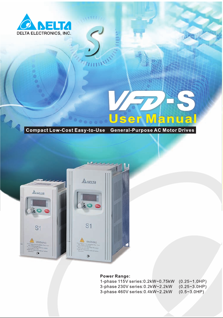
1.1.1 Nameplate Information
Example for 1HP/0.75kW 3-phase 230V AC motor drive
AC Drive Model
Input Spec.
Output Frequency Range
Serial Number & Bar Code
Output Spec.
MOD EL : VFD 007S2 3A
INPUT : 3PH 200-240V 50/60Hz 5.1A
OUTPUT : 3PH 0-240V 4.2A 1.6kVA 0.75kW/ 1HP
Frequenc y Range : 1-400Hz
007S23A0T70 10001
DELTA ELECTRONI CS INC.
MADE IN XXXXX
1.1.2 Model Explanation
007
VFD
23
Ver si on Type
Input Voltage
11:Single phase 115V
21:Single phase 230V
23:Three phase 230V
43:Three phase 460V
S Series
Applicable motor capacity
002: 0.25HP(0.2kW)
004: 0.5HP(0.4kW)
007: 1 HP(0.7kW)
Series Name
Revision August 2008, SE09, SW V2.61 1-1
022: 3 HP(2.2kW)
Page 11
Chapter 1 Introduction|VFD-S Series
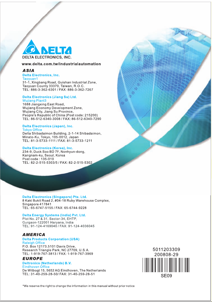
1.1.3 Series Number Explanation
0160T007S23A
Production number
Production week
Production year 2006
Production factory
230V 3-phase 1HP(0.75kW)
(Taoyuan)
Model
If the nameplate information does not correspond to your purchase order or if there are
any problems, please contact your distributor.
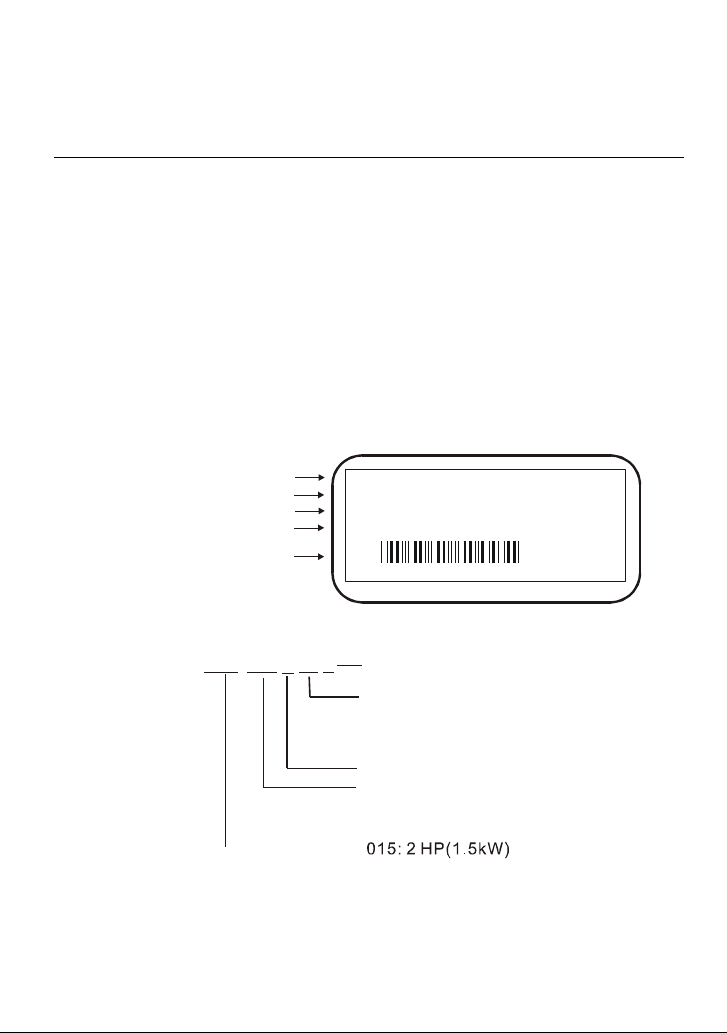
1.1.4 Drive Frames
Frame Power range Models
S1
S2
Please refer to Chapter 2.3 for exact dimensions.
0.25-2hp
(0.2-1.5kW)
1-5hp
(0.75-3.7kW)
VFD002S11A/11B/21A/21B/21E/23A,
VFD004S11A/11B/21A/21B/21E/23A/43A/43B/43E,
VFD007S21A/21B/21E/23A/43A/43B/43E, VFD015S23D
VFD007S11A/11B, VFD015S21D/21E/21U/43D/43E/43U,
VFD022S21D/21E/21U/23D/43D/43E/43U
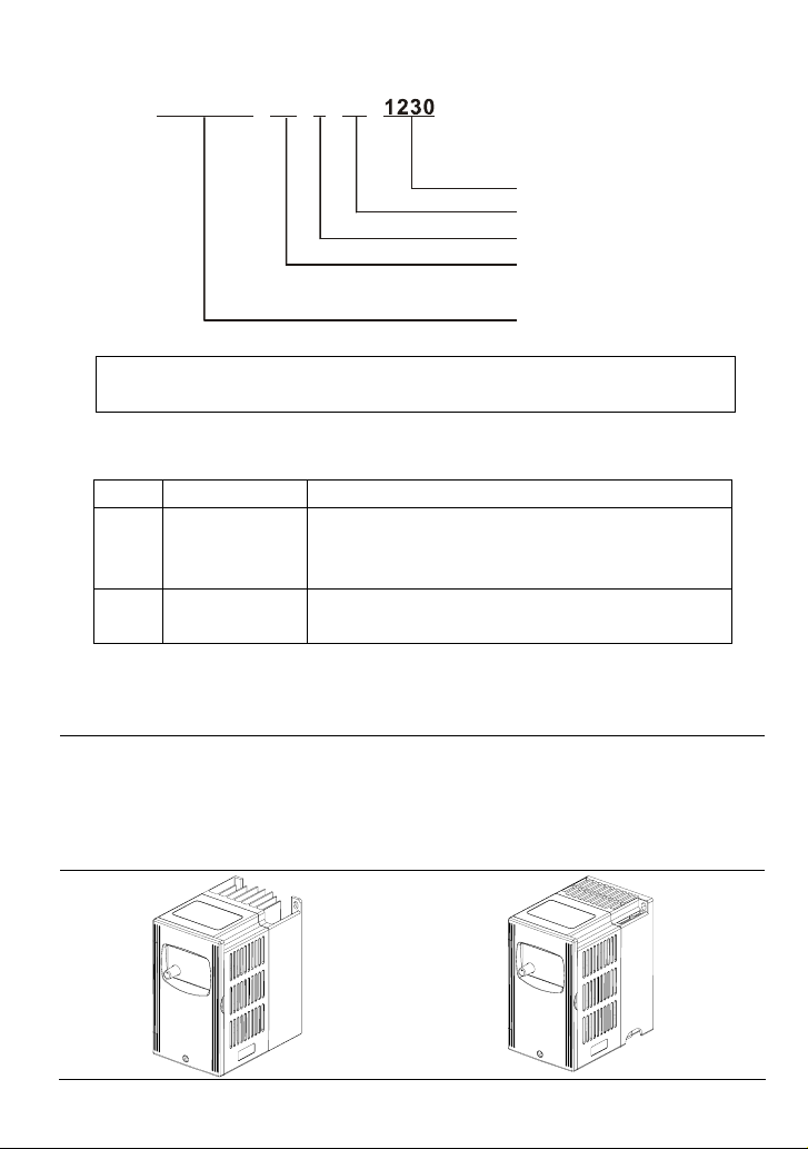
1.2 Appearances
VFD002S11A/11B/21A/21B/23A,
VFD004S11A/11B/21A/21B/23A/43A/43B/43E,
VFD007S21A/21B/23A/43A/43B/43E,
1-2 Revision August 2008, SE09, SW V2.61
Frame S1: VFD002S21E, VFD004S21E,
VFD007S21E, VFD015S23D,
Frame S2: VFD007S11A/11B,
VFD015S21D/21E/21U/43D/43E/43U,
VFD022S21D/21E/21U/23D/43D/43E/43U
Page 12
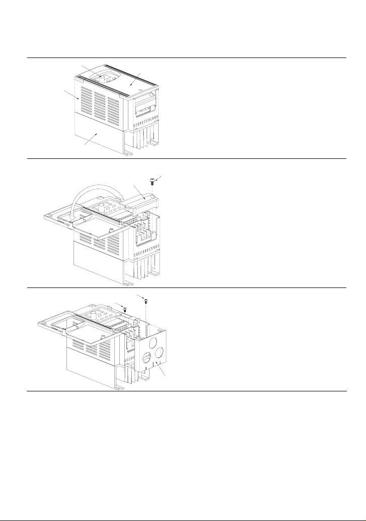
1.3 Installation Steps
T
Chapter 1 Introduction|VFD-S Series
CASE
KNOB
HEAT SINK
DIVISION
PLATE
SCREW
COVER
SCREW
SCREW
Installation Steps
1. Remove front cover screw and open.
2. Remove Division Plate. If using optional
conduit bracket, please refer to next
page.
3. Connect AC Input Power and motor leads.
Never connect the AC drive output
terminals U/T1, V/T2, W/T3 to main AC
Input power.
4. Reinstall Division Plate.
For Optional Conduit Bracket:
Make sure to fasten both screws on conduit
bracket as shown in the drawing for safety
grounding purpose. Bring all the wires out
through the conduit bracket.
Screw Torque: 5 to 6 kgf-cm (4.3 to 5.2 in-lbf)
CONDUIT
BRACKE
Revision August 2008, SE09, SW V2.61 1-3
Page 13
Chapter 1 Introduction|VFD-S Series
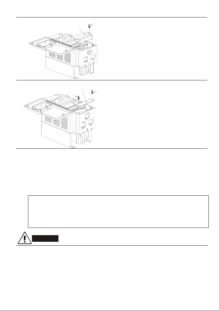
W
T
DIVISION
PLATE
SCREW
Reinstall Division Plate.
Screw Torque: 5 to 6 kgf-cm (4.3 to 5.2 in-lbf)
CONDUI
BRACKET
SCREW
SCRE
Install Conduit Bracket cover and tighten screws.
1.4 Storage
The AC motor drive should be kept in the shipping carton or crate before installation. In order to
retain the warranty coverage, the AC motor drive should be stored properly when it is not to be used
for an extended period of time. Storage conditions are:
Store in a clean and dry location free from direct sunlight or corrosive fumes.
Store within an ambient temperature range of -20 °C to +60 °C.
Store within a relative humidity range of 0% to 90% and non-condensing environment.
Store within an air pressure range of 86kPa to 106kPa.
CAUTION!
1. DO NOT store in an area with rapid changes in temperature. It may cause condensation and
frost.
2. DO NOT place on the ground directly. It should be stored properly. Moreover, if the surrounding
environment is humid, you should put exsiccator in the package.
1-4 Revision August 2008, SE09, SW V2.61
Page 14

Chapter 1 Introduction|VFD-S Series
3. If the AC motor drive is stored for more than 3 months, the temperature should not be higher
than 30 °C. Storage longer than one year is not recommended, it could result in the degradation
of the electrolytic capacitors.
4. When the AC motor drive is not used for a long time after installation on building sites or places
with humidity and dust, it’s best to move the AC motor drive to an environment as stated above.
Revision August 2008, SE09, SW V2.61 1-5
Page 15

Chapter 1 Introduction|VFD-S Series
This page intentionally left blank.
1-6 Revision August 2008, SE09, SW V2.61
Page 16

Chapter 2 Installation and Wiring
2.1 Ambient Conditions
Install the AC motor drive in an environment with the following conditions:
Operation Air Temperature: -10 ~ +40°C (14 ~ 104°F), Non-condensing
Relative Humidity: <90%, no condensation allowed
Atmosphere pressure: 86 ~ 106 kPa
Installation Site Altitude: <1000m
Vibration: <20Hz: 9.80 m/s
20 ~ 50Hz: 5.88 m/s
Storage
Transportation
Pollution Degree 2: good for a factory type environment.
Temperature: -20°C ~ +60°C (-4°F ~ 140°F)
Relative Humidity: <90%, no condensation allowed
Atmosphere pressure: 86 ~ 106 kPa
Vibration: <20Hz: 9.80 m/s
20 ~ 50Hz: 5.88 m/s
and not frozen
2
(1G) max
2
(0.6G) max
2
(1G) max
2
(0.6G) max
CAUTION!
1. Operating, storing or transporting the AC motor drive outside these conditions may cause
damage to the AC motor drive.
2. Failure to observe these precautions may void the warranty!
2.2 Installation
1. Mount the AC motor drive vertically on a flat vertical surface by using bolts or screws. Other
directions are not allowed.
2. The AC motor drive will generate heat during operation. Allow sufficient space around the unit
for heat dissipation.
3. The heat sink temperature may rise to 90°C when running. The material on which the AC motor
drive is mounted must be noncombustible and be able to withstand this high temperature.
4. When the AC motor drive is installed in a confined space (e.g. cabinet), the surrounding
temperature must be within 10 ~ 40°C with good ventilation. DO NOT install the AC motor drive
in a space with bad ventilation.
Revision August 2008, SE09, SW V2.61 2-1
Page 17
Chapter 2 Installation and Wiring|VFD-S Series
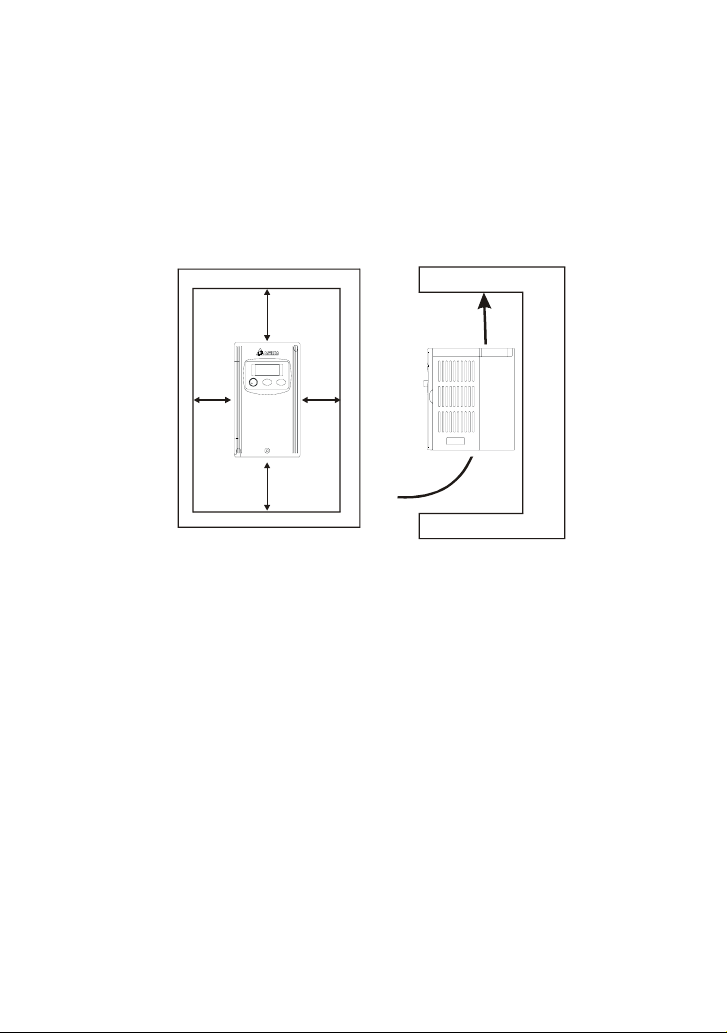
5. When installing multiple AC motor drives in the same cabinet, they should be adjacent in a row
with enough space. When installing one AC motor drive below another one, use a metal
separation barrier between the AC motor drives to prevent mutual heating. Refer to figure below
for details.
6. Prevent fiber particles, scraps of paper, saw dust, metal particles, etc. from adhering to the
heatsink.
Mounting Clearances
150mm
(6inch)
50mm
(2inch)
50mm
(2inch)
Air Flow
150mm
(6inch)
2-2 Revision August 2008, SE09, SW V2.61
Page 18
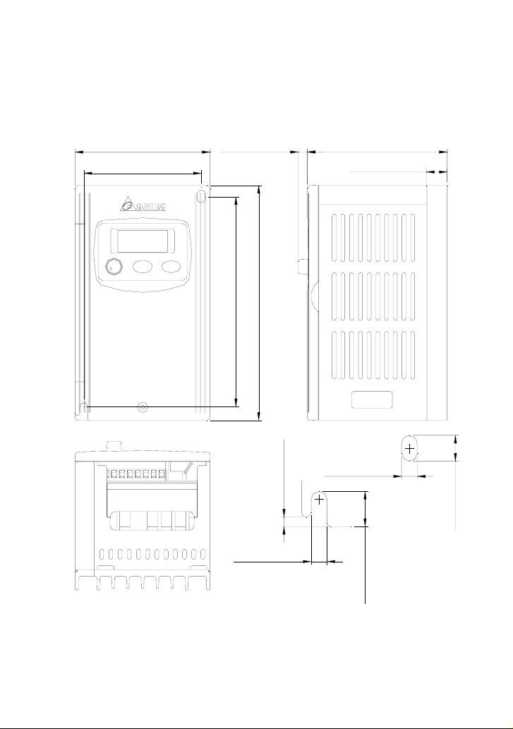
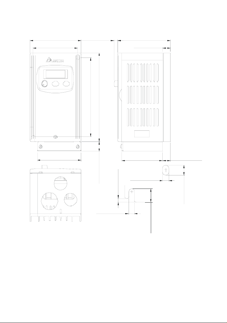
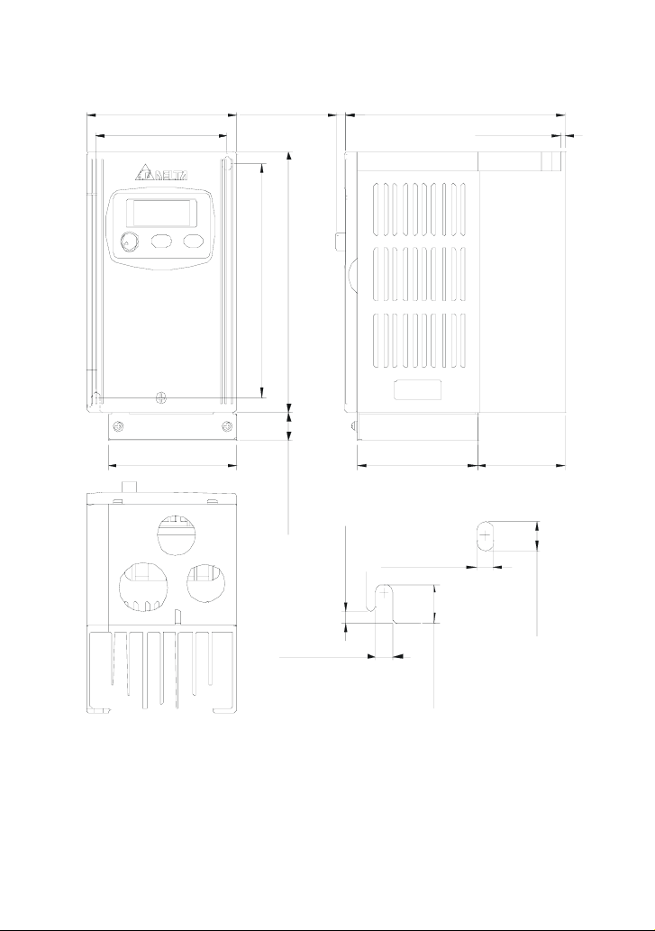
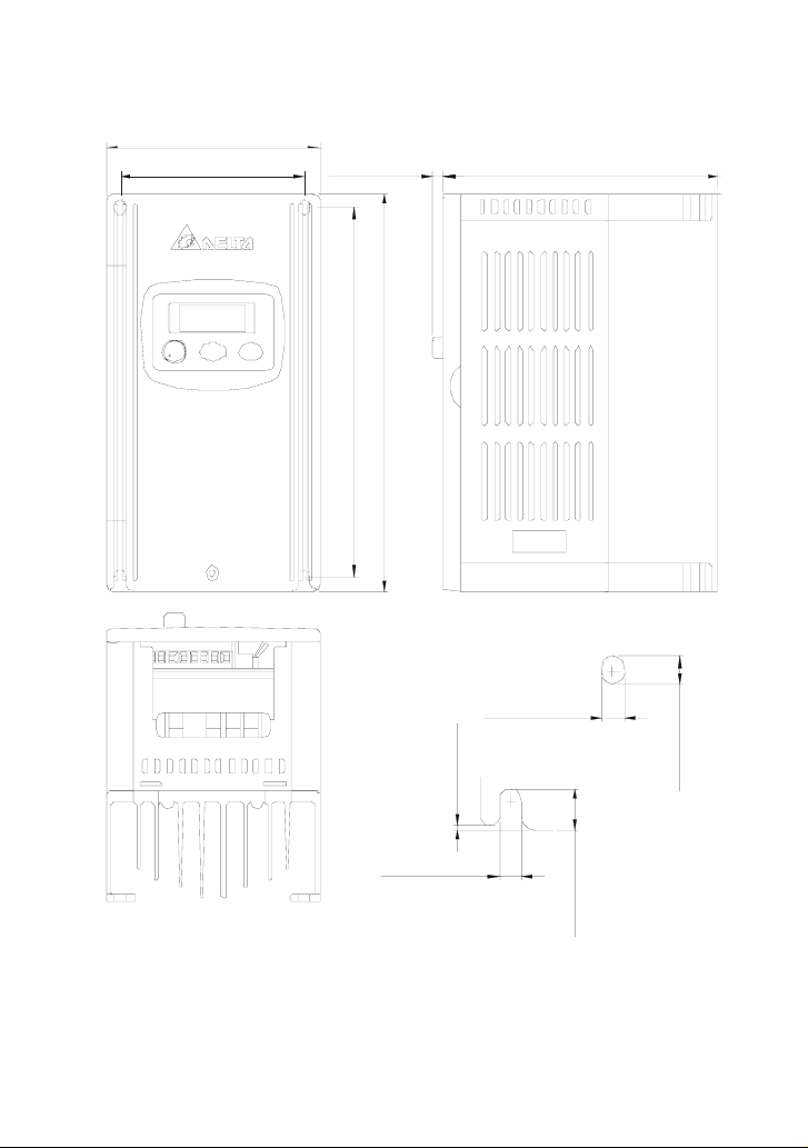
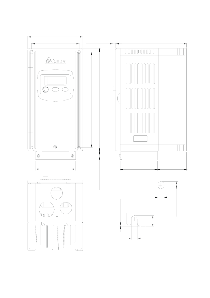
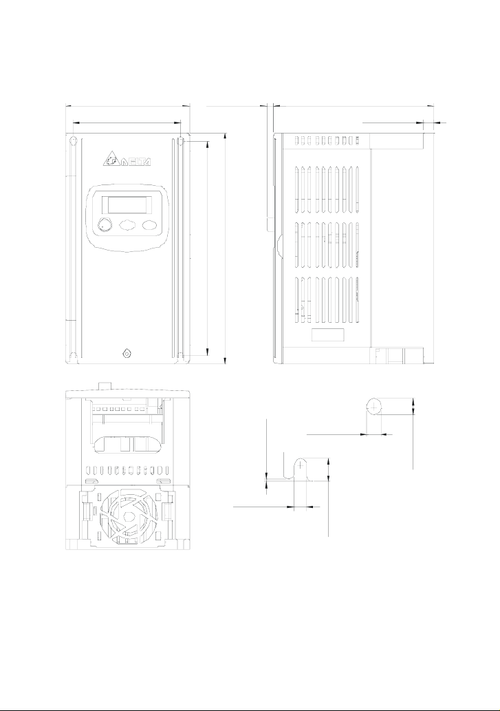
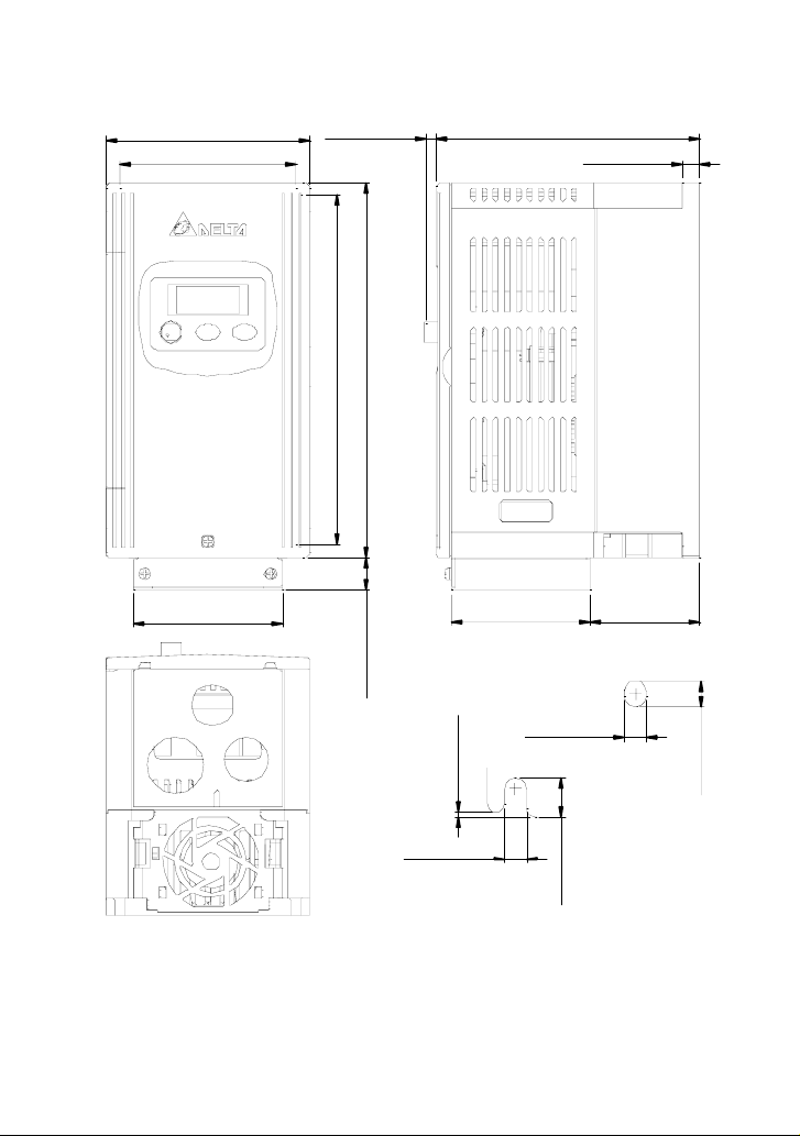
2.3 Dimensions
(Dimensions are in millimeter and [inch])
Frame S1: VFD002S11A, VFD002S21A, VFD002S23A
85.0 [3.35]
74.0 [2.92]
]
]
1
3
2
8
.
.
5
5
[
[
2
0
.
.
2
8
3
4
1
1
Chapter 2 Installation and Wiring|VFD-S Series
88.0 [3.47]5.8 [0.23]
13.0 [0.51]
]
2
1
.
0
[
0
.
3
5.0 [0.20]
Revision August 2008, SE09, SW V2.61 2-3
5.0 [0.20]
]
4
4
.
0
[
1
.
1
1
]
2
3
.
0
[
1
.
8
Page 19
Chapter 2 Installation and Wiring|VFD-S Series
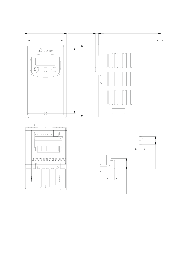
Frame S1: VFD002S11B, VFD002S21B
85 .0 [3 .3 5 ]
74 .0 [2 .9 2 ]
]
]
3
1
8
2
.
.
5
5
[
[
0
2
.
.
8
2
4
3
1
1
88 .0 [3 .4 7 ]5.8 [0.23 ]
13 .0 [0 .5 1 ]
73 .0 [2 .8 8 ]
]
3
6
.
0
[
0
.
6
1
5.0 [0.20 ]
2-4 Revision August 2008, SE09, SW V2.61
]
2
1
.
0
[
0
.
3
67 .8 [2 .6 7 ]
5.0 [0.20 ]
]
4
4
.
0
[
1
.
1
1
13 .0 [0 .5 1 ]
]
2
3
.
0
[
1
.
8
Page 20
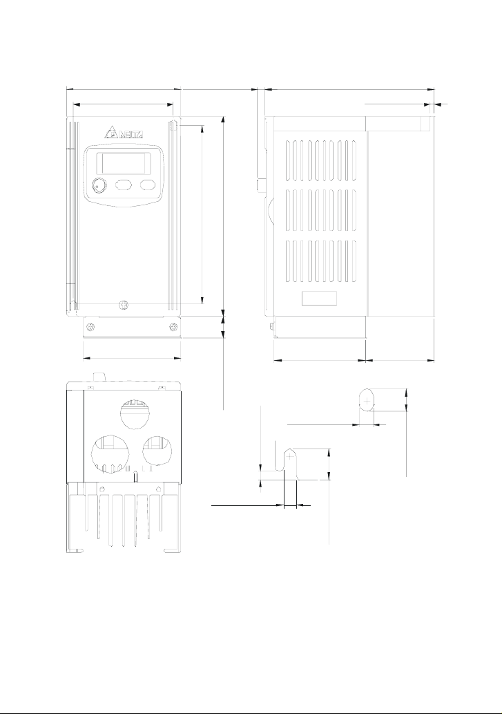
Frame S1: VFD004S11A, VFD004S21A, VFD004S23A
5.8 [0.23]
74 .0 [2 .9 2]
]
]
3
1
8
2
.
.
5
5
[
[
0
2
.
.
8
2
4
3
1
1
5.0 [0.20]
Chapter 2 Installation and Wiring|VFD-S Series
102.0 [4.02]85 .0 [3 .3 5]
2.8 [0.11 ]
]
2
1
5.0 [0.20 ]
.
0
[
0
.
3
]
4
4
.
0
[
1
.
1
1
]
2
3
.
0
[
1
.
8
Revision August 2008, SE09, SW V2.61 2-5
Page 21
Chapter 2 Installation and Wiring|VFD-S Series
Frame S1: VFD004S11B, VFD004S21B
85 .0 [3 .3 5]
74 .0 [2 .9 2]
74 .0 [2 .9 2]
5.8 [0.23 ]
]
]
1
3
2
8
.
.
5
5
[
[
2
0
.
.
2
8
3
4
1
1
102.0 [4.02]
2.8 [0.11 ]
73 .0 [2 .8 8]
]
3
6
.
0
[
0
.
6
1
5.0 [0.20 ]
2-6 Revision August 2008, SE09, SW V2.61
]
2
1
.
0
[
0
.
3
67 .8 [2 .6 7]
5.0 [0.20 ]
]
4
4
.
0
[
1
.
1
1
27 .0 [1 .0 6]
]
2
3
.
0
[
1
.
8
Page 22
Frame S1: VFD007S21A, VFD007S23A
85 .0 [3 .3 5]
5.8 [0.23 ]
74 .0 [2 .9 2]
]
1
2
.
5
[
2
.
2
3
1
]
3
8
.
5
[
0
.
8
4
1
5.0 [0.20]
Chapter 2 Installation and Wiring|VFD-S Series
124.0 [4.89]
2.8 [0.11]
]
2
5.0 [0.20]
1
.
0
[
0
.
3
]
4
4
.
0
[
1
.
1
1
]
2
3
.
0
[
1
.
8
Revision August 2008, SE09, SW V2.61 2-7
Page 23
Chapter 2 Installation and Wiring|VFD-S Series
Frame S1: VFD007S21B
85 .0 [3 .3 5]
74 .0 [2 .9 2]
74 .0 [2 .9 2]
5.8 [0.23]
]
]
3
1
8
2
.
.
5
5
[
[
0
2
.
.
8
2
4
3
1
1
12 4.0 [4.89]
2.8 [0.11]
]
2
1
.
0
[
0
.
3
67 .8 [2 .6 7]
5.0 [0.20 ]
73 .0 [2 .8 8]
]
3
6
.
0
[
0
.
6
1
5.0 [0.20]
2-8 Revision August 2008, SE09, SW V2.61
]
4
4
.
0
[
1
.
1
1
50 .0 [1 .9 7]
]
2
3
.
0
[
1
.
8
Page 24
Chapter 2 Installation and Wiring|VFD-S Series
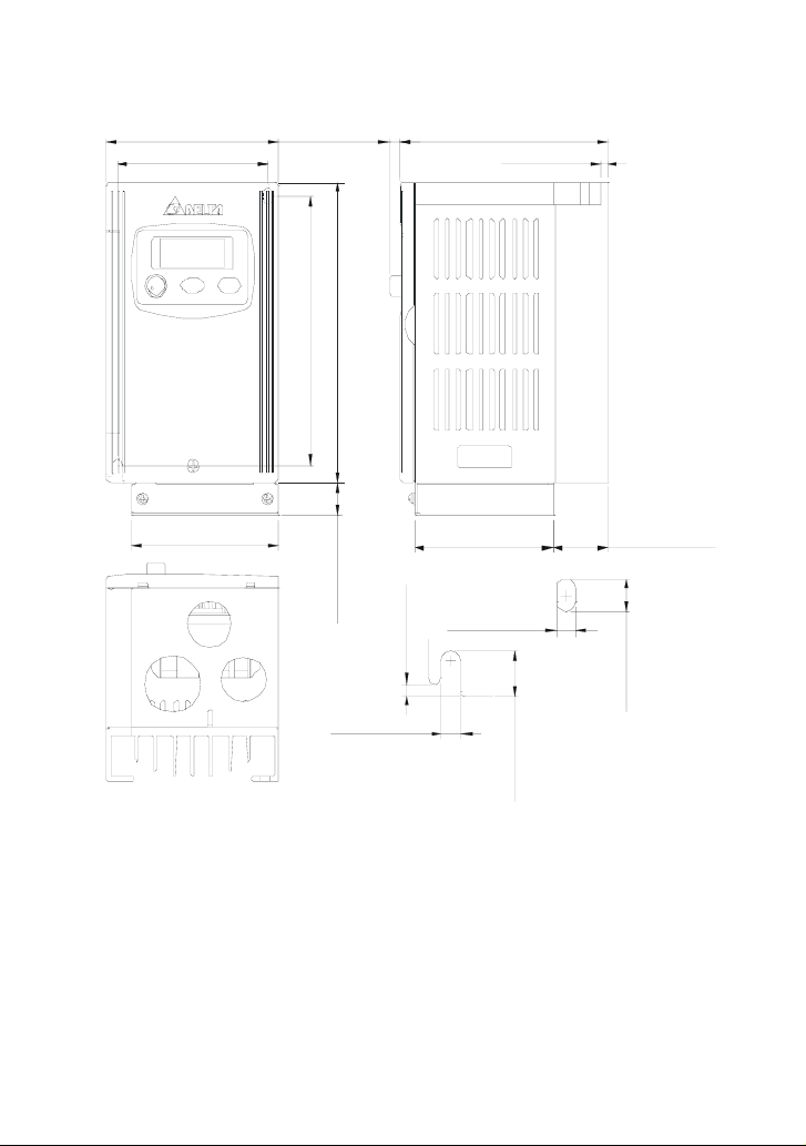
Frame S1: VFD004S43A, VFD004S43E, VFD007S43A, VFD007S43E
85 .0 [3 .3 5]
5.8 [0.23 ]
126.0 [4.96]
74 .0 [2 .9 2]
]
]
1
3
2
8
.
.
5
5
[
[
2
0
.
.
2
8
3
4
1
1
]
2
5.0 [0.20 ]
1
.
0
[
0
.
3
5.0 [0.20 ]
]
4
4
.
0
[
1
.
1
1
3.0 [0.12 ]
]
2
3
.
0
[
1
.
8
Revision August 2008, SE09, SW V2.61 2-9
Page 25
Chapter 2 Installation and Wiring|VFD-S Series
Frame S1: VFD004S43B, VFD007S43B
85 .0 [3 .3 5]
5.8 [0.23 ]
74 .0 [2 .9 2]
]
]
3
1
8
2
.
.
5
5
[
[
0
2
.
.
8
2
4
3
1
1
126.0 [4.96]
3.0 [0.12 ]
73 .0 [2 .8 8]
]
3
6
.
0
[
0
.
6
1
5.0 [0.20 ]
2-10 Revision August 2008, SE09, SW V2.61
]
2
1
.
0
[
0
.
3
67 .8 [2 .6 7]
5.0 [0.20 ]
]
4
4
.
0
[
1
.
1
1
51 .0 [2 .0 1]
]
2
3
.
0
[
1
.
8
Page 26
Chapter 2 Installation and Wiring|VFD-S Series
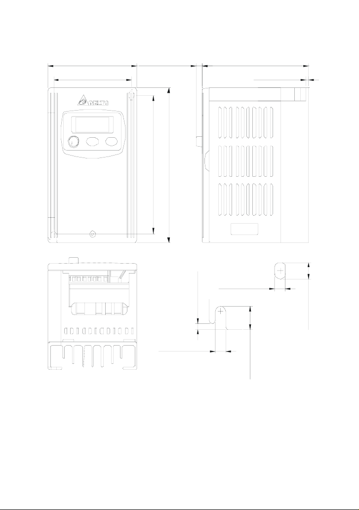
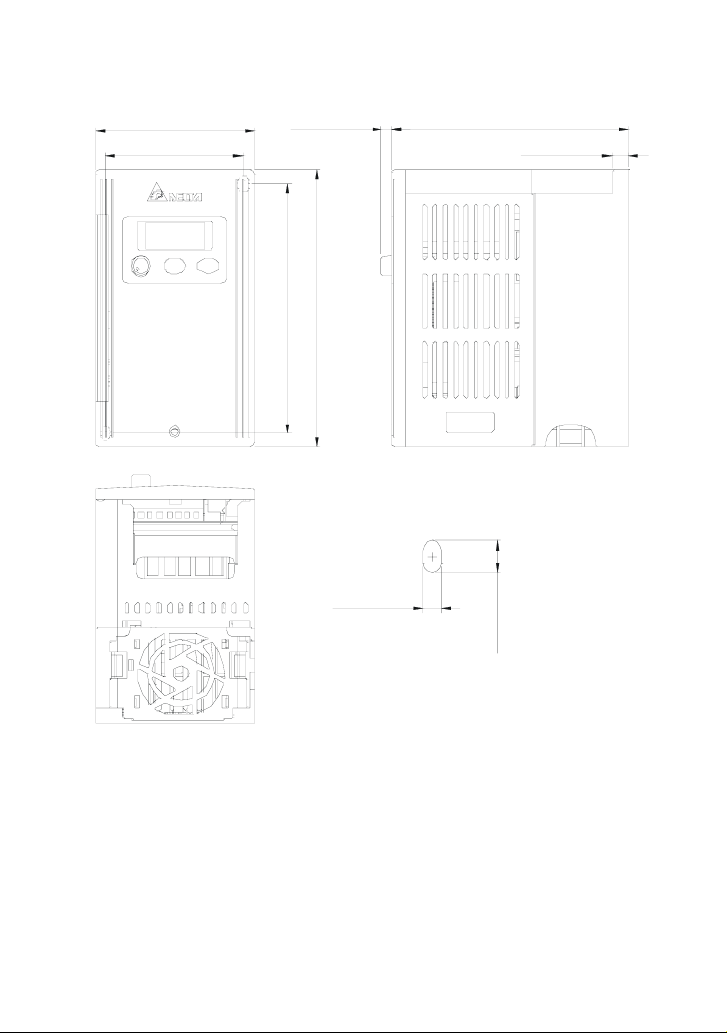
Frame S1: VFD002S21E, VFD004S21E, VFD007S21E, VFD015S23D
85 .0 [3 .3 5]
5.8 [0.23] 127.0 [5.00]
74 .0 [2 .9 2]
]
]
7
3
2
8
.
.
5
5
[
[
7
0
.
.
3
8
3
4
1
1
5.0 [0.20 ]
8.5 [0.33 ]
]
3
3
.
0
[
3
.
8
Revision August 2008, SE09, SW V2.61 2-11
Page 27
Chapter 2 Installation and Wiring|VFD-S Series
Frame S2: VFD007S11A
100.0 [3.94]
86 .5 [3 .4 1 ]
5.4 [0.21 ]
]
1
8
.
6
[
0
.
3
7
1
129.0 [5.08]
]
3
3
.
7
[
0
.
6
8
1
5.5 [0.22 ]
]
4
0
.
0
[
0
.
1
5.5 [0.22 ]
2-12 Revision August 2008, SE09, SW V2.61
]
8
3
.
0
[
5
.
9
]
6
2
.
0
[
5
.
6
Page 28
Frame S2: VFD007S11B
100.0 [3.94]
86 .5 [3 .4 1]
5.4 [0.21 ]
]
]
3
2
3
8
.
.
7
6
[
[
0
0
.
.
6
3
8
7
1
1
Chapter 2 Installation and Wiring|VFD-S Series
129.0 [5.08]
73 .0 [2 .8 8]
]
3
6
.
0
[
0
.
6
1
5.5 [0.22]
Revision August 2008, SE09, SW V2.61 2-13
67 .8 [2 .6 7]
5.5 [0.22 ]
]
4
0
.
0
[
0
.
1
53.5 [2.11]
]
8
3
.
0
[
5
.
9
]
6
2
.
0
[
5
.
6
Page 29
Chapter 2 Installation and Wiring|VFD-S Series
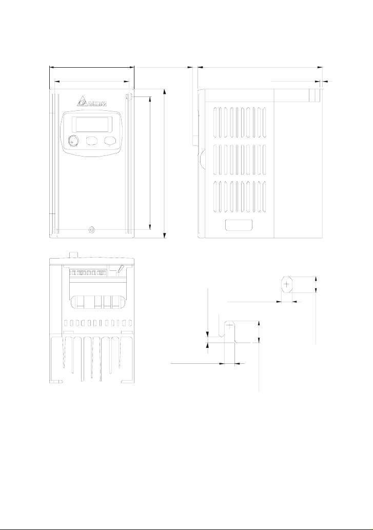
Frame S2: VFD015S21D, VFD015S21E, VFD015S43D, VFD015S43E, VFD022S21D,
VFD022S21E, VFD022S23D, VFD022S43D, VFD022S43E
100.0 [3.94]
86 .5 [3 .4 1 ]
5.4 [0.21 ] 129.3 [5.09]
8.5 [0.33 ]
]
]
2
3
8
3
.
.
6
7
[
[
0
0
.
.
6
3
8
7
1
1
]
4
0
.
0
[
0
.
1
5.5 [0.22 ]
2-14 Revision August 2008, SE09, SW V2.61
5.5 [0.22 ]
]
7
3
.
0
[
5
.
9
]
6
2
.
0
[
5
.
6
Page 30
Chapter 2 Installation and Wiring|VFD-S Series
Frame S2: VFD015S21U, VFD015S43U, VFD022S21U, VFD022S43U
100.0 [3.94]
129.3 [5.09]5.4 [0.21]
86.5 [3.41]
173.0 [6.82]
186.0 [7.33]
8.5 [0.33]
73.0 [2.88]
67.8 [2.67] 53.9 [2.12]
16.0 [0.63]
5.5 [0.22]
1.0 [0.04]
6.5 [0.26]
5.5 [0.22]
9.5 [0.37]
Revision August 2008, SE09, SW V2.61 2-15
Page 31

Chapter 2 Installation and Wiring|VFD-S Series
2.4 Wiring
After removing the front cover, check if the power and control terminals are clear of debris. Be sure
to observe the following precautions when wiring.
General Wiring Information
Applicable Codes
All VFD-S series are Underwriters Laboratories, Inc. (UL) and Canadian Underwriters
Laboratories (cUL) listed, and therefore comply with the requirements of the National Electrical
Code (NEC) and the Canadian Electrical Code (CEC).
Installation intended to meet the UL and cUL requirements must follow the instructions provided
in “Wiring Notes” as a minimum standard. Follow all local codes that exceed UL and cUL
requirements. Refer to the technical data label affixed to the AC motor drive and the motor
nameplate for electrical data.
The "Line Fuse Specification" in Appendix B, lists the recommended fuse part number for each
S-Series part number. These fuses (or equivalent) must be used on all installations where
compliance with U.L. standards is a required.
2-16 Revision August 2008, SE09, SW V2.61
Page 32

Chapter 2 Installation and Wiring|VFD-S Series
2.4.1 Basic Wiring
Make sure that power is only applied to the R/L1, S/L2, T/L3 terminals. Failure to comply
may result in damage to the equipment. The voltage and current should lie within the
range as indicated on the nameplate.
Check the following items after completing the wiring:
1. Are all connections correct?
2. No loose wires?
3. No short-circuits between terminals or to ground?
A charge may still remain in the DC bus capacitors with hazardous voltages even if the power
has been turned off. To prevent personal injury, please ensure that the power is turned off and
wait ten minutes for the capacitors to discharge to safe voltage levels before opening the AC
motor drive.
DANGER!
1. All the units must be grounded directly to a common ground terminal to prevent electric shock,
fire and interference.
2. Only qualified personnel familiar with AC motor drives are allowed to perform installation, wiring
and commissioning.
3. Make sure that the power is off before doing any wiring to prevent electric shocks.
Basic Wiring Diagrams
Users must connect wires according to the circuit diagrams on the following pages. Do not plug a
modem or telephone line to the RS-485 communication port or permanent damage may result. Pins
1 & 2 are the power supply for the optional copy keypad only and should not be used for RS-485
communication.
Revision August 2008, SE09, SW V2.61 2-17
Page 33
Chapter 2 Installation and Wiring|VFD-S Series
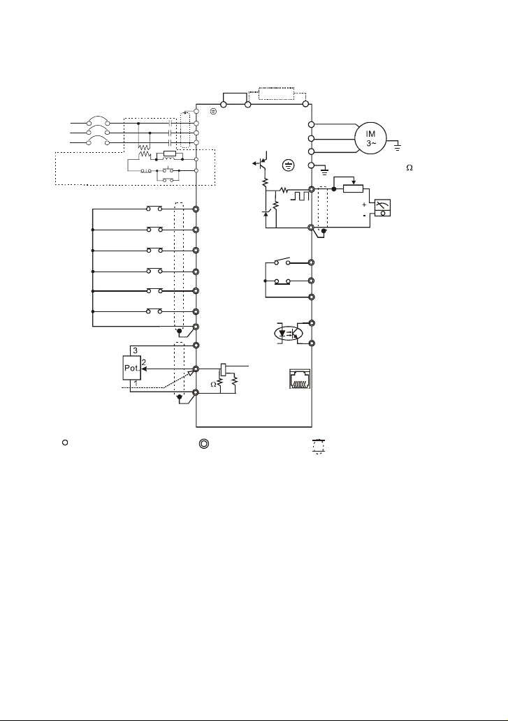
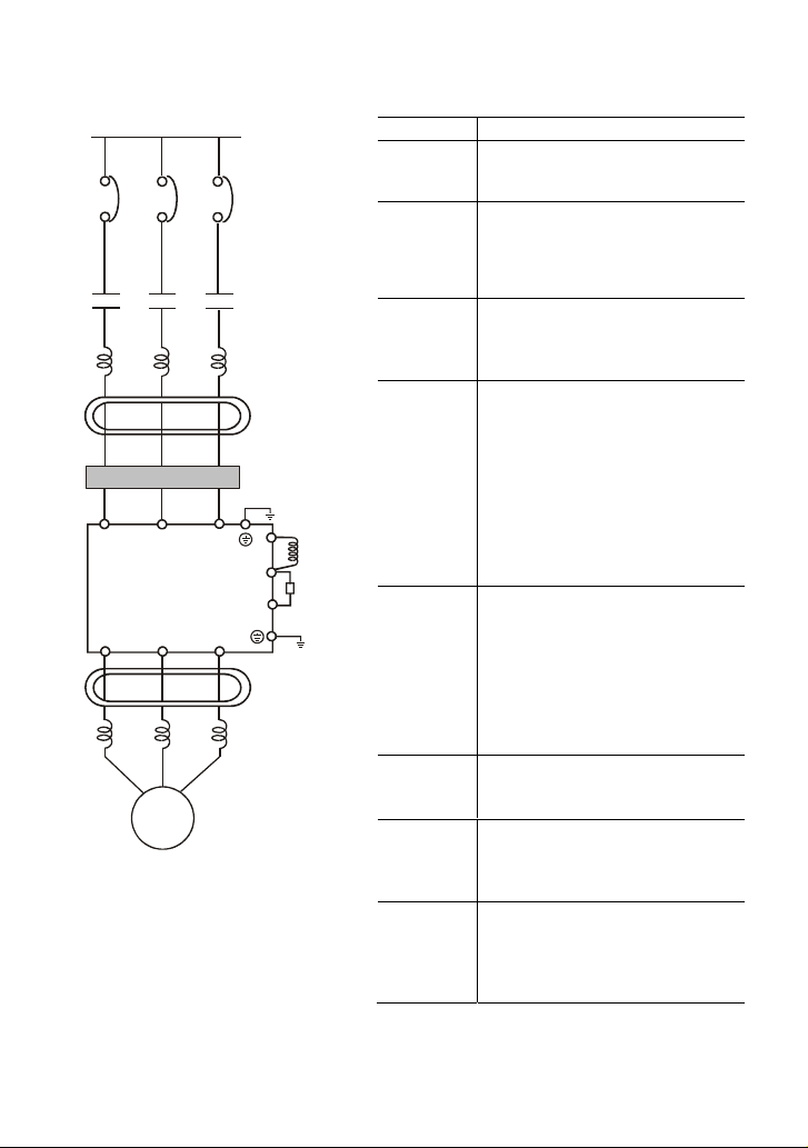
For VFDXXXSXXA/B/D/U
Jumper
Main Ci rcu it Power
NFB
R/L1
S/L2
T/L3
Recommended Circuit
when power supply
is tu rned O FF by a
fault output
Analog volta ge
0~10VDC
Potentiometer
Ω
3K~5K
Analog current
4~20mA
Factory sett ing: output freq. (Pot .)
determined by the Potentiometer
on the control panel.
Main circuit (power) terminals
OFF
Factory setting
Forward/ Stop
Reverse/S top
Reset
Multi-st ep 1
Multi-st ep 2
Multi-st ep 3
Common signal
NOTE:
Do not plug in a modem or telephone line to the RS-485 communication
port, permanent damage may result. Pins 1&2 are the power
sources for the optional copy keypad and should not be used while
using RS-485 communication.
﹡
If it is single phase model, please select any of the two input power
terminals in main circuit power.
E
+1
R/L1
S/L2
T/L3
SA
RB
MC
RC
ON
MC
M0
M1
M2
M3
M4
M5
GND
+10V 10mA
(MAX)
2
AVI
47K
GND
Control circuit terminals
3
Brake Resistor (optional)
+2/B1
17V
CPU
2.4K
Ω47Ω
11V
1
250
Ω
Ω Ω
select 80 120W, 200 120W,
400 120W
Ω
V/T2
W/T3
47K
B2
U/T1
E
AFM
Ω
GND
RA
RB
RC
MO1
MCM
RJ-11
6->1
AC Motor
Grounding resistance
less than 100
Potenti ometer (1K )
Factory setting: indicate
output frequency
Multi-function indication
output contacts below
120VAC/24VDC 5A
240VAC less than 2.5A
Factory setting:
indicates malfunction
Multi-function Photocoupler
output below 48VDC 50mA
Factory setting: indicates
during operation
RJ-11 communication port with
RS-485 serial communication interface
1: 17V
2: GND
3: SG4: SG+
5: NC
6: Communication
Shielded leads
Ω
Analog output
DC 0~10V
2-18 Revision August 2008, SE09, SW V2.61
Page 34
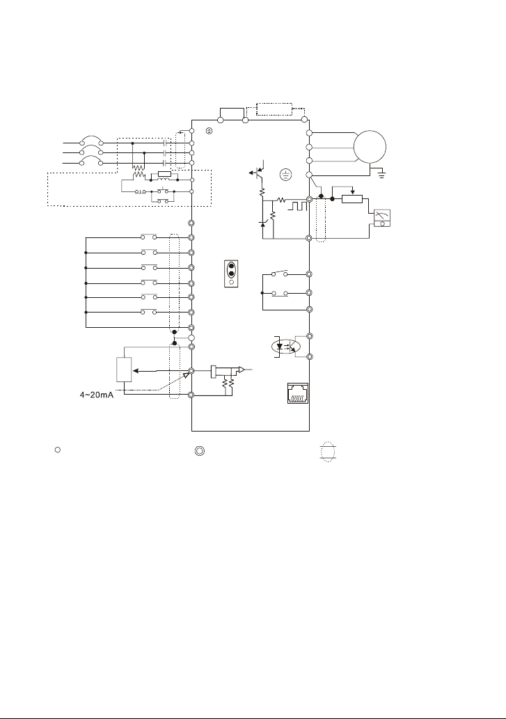
For VFDXXXSXXE
NPN (sink mode)
Main Circuit Power
NFB
R/L1
S/L2
T/L3
Recommended Circuit
when power supply
is turned OFF by a
fault output
Analog voltage
010VDC
Potenti ometer
3K 5K~~Ω
Analog current
Factory setting: outpu t freq. (Pot.)
determined by the Potentiometer
on the control panel.
Main circuit (power ) terminals
OFF
Factory setting
Forward/Stop
Reverse/St op
Reset
Multi-step 1
Multi- step 2
Multi-step 3
Comm. signal (sink)
3
2
Pot.
1
NOTE: Do not plug in a Modem or telephone line to the RS-485 communication
port, permanent damage may result. Pins 1 & 2 are the power
sources for the optional copy keypad and should not be used while
using RS -485 communi cation.
* If it is single phase model, please select any of the two input power
terminal s in main circuit power.
Chapter 2 Installation and Wiring|VFD-S Series
Jumper
+1
E
R/L1
S/L2
T/L3
SA
RB
MC
RC
ON
MC
17V
M0
M1
M2
M3
M4
M5
GND
E
+10V 10mA
(MAX)
1
2
AVI
3
Ω
250
GND
Control circuit terminals
Brake Resistor (optional)
+2/B1
+17V
CPU
Ω
2.4
47
47K
11V
NPN
PNP
J2
47K
Ω
ΩΩ
120W, 200 1 20W
400 120W
Ω
AC Motor
IM
3~
Grounding resist ance
less than 100
Potentiom eter(1K )
Analog output
+
DC 0 10V
-
Factory setting: indicate
output frequency
Multi-function indication
output contacts below
120VAC/24VDC 5A
Factory setting:
indicates malfunction
Multi-function Photocoupler
output below 48VDC 50mA
Factory setting: Indicates
during operation
RJ-11 communication port with
RS-485 serial communication interface
V
1:17
2:GND
3:SG4:SG+
Shielded leads
B2
U/T1
V/T2
W/T3
AFM
Ω
Ω
GND
RB
MO1
MCM
RJ-11
61
select 80
E
RA
RC
←
Ω
Ω
~
Revision August 2008, SE09, SW V2.61 2-19
Page 35
Chapter 2 Installation and Wiring|VFD-S Series
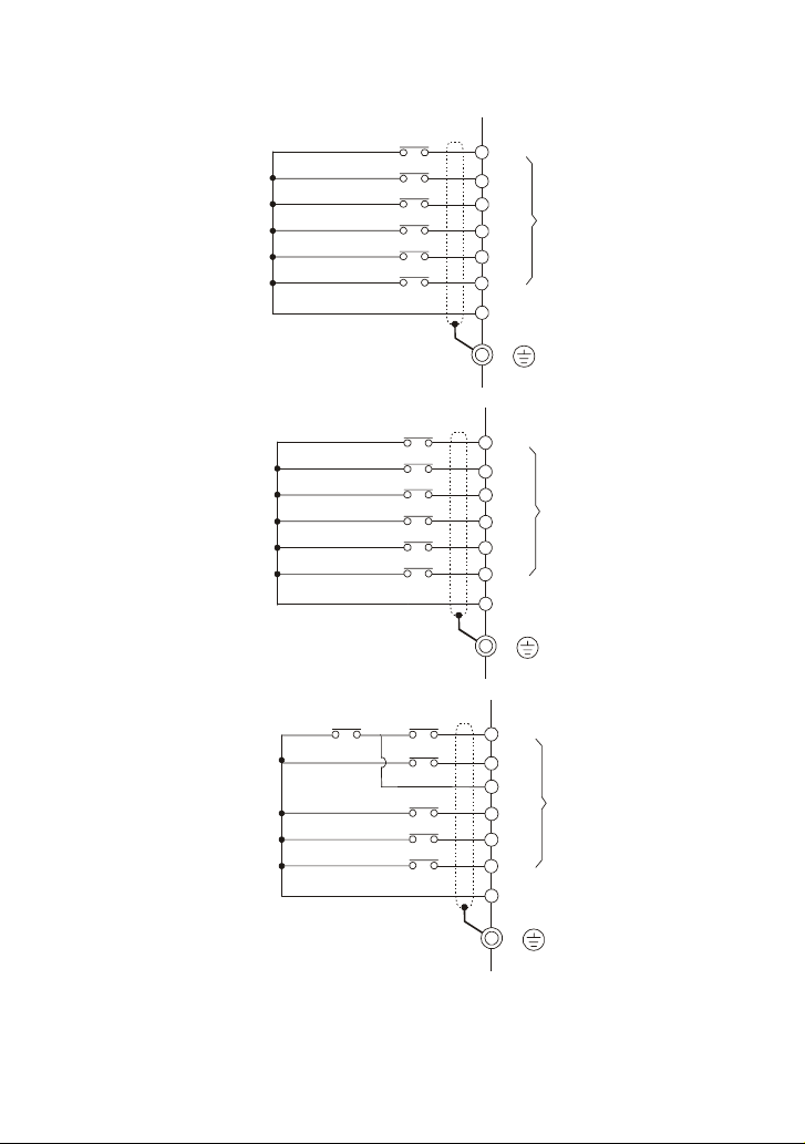
Two/Three wire control
The wiring for
Pr.4-04=d1
The wiring for
Pr.4-04=d2
The wiring for
Pr.4-04=d3
Forward/Stop
Reverse/Stop
Reset
Multi-step 1
Multi-step 2
Multi-step 3
Common Signal
Run/Stop
Forward/Reverse
Reset
Multi-step 1
Multi-step 2
Multi-step 3
Common Signal
Stop
Multi-step 1
Multi-step 2
Multi-step 3
Common Signal
Run
REV/FWD
M0
M1
M2
M3
M4
M5
GND
E
M0
M1
M2
M3
M4
M5
GND
E
M0
M1
M2
M3
M4
M5
GND
Multi-function
Input Terminals
Multi-function
Input Terminals
Multi-function
Input Terminals
E
2-20 Revision August 2008, SE09, SW V2.61
Page 36
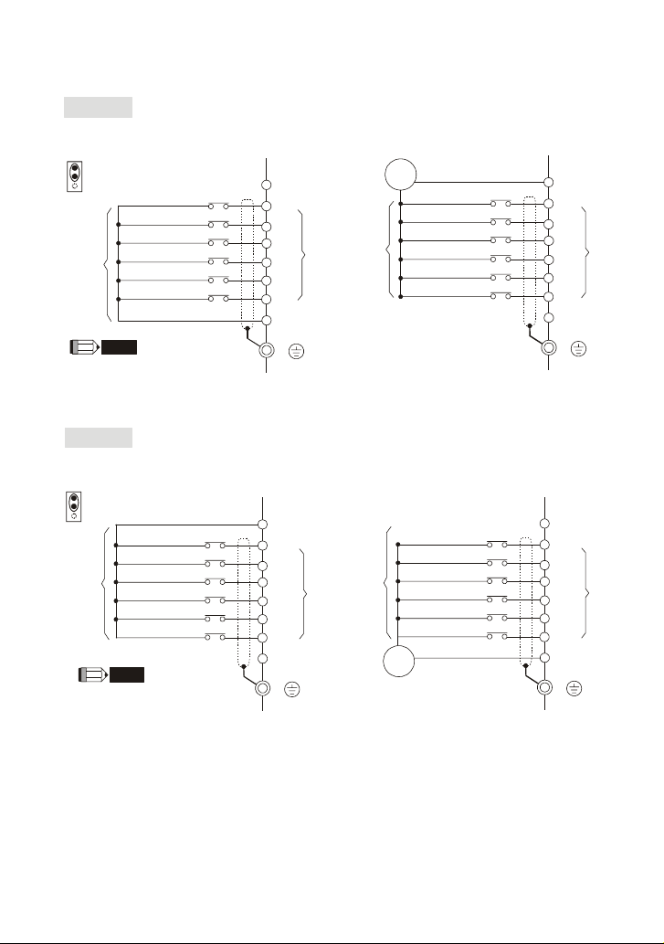
For VFDXXXSXXE
V
V
NPN Mode
Chapter 2 Installation and Wiring|VFD-S Series
NPN mode without external power
NPN
PNP
J2
Don't apply the mains voltage
directly to above terminals.
y
g
r
n
o
i
t
t
t
c
e
a
S
F
NOTE
Forward/Stop
Reverse/Stop
Reset
Multi-step 1
Multi-step 2
Multi-step 3
Common Signal
PNP Mode
PNP mode without external power
NPN
PNP
J2
y
g
r
n
o
i
t
t
t
c
e
a
S
F
Forward/Stop
Reverse/Stop
Reset
Multi-step 1
Multi-step 2
Multi-step 3
NOTE
Don't apply the mains voltage
directly to above terminals.
+17V
M0
M1
M2
M3
M4
M5
GND
E
+17V
M0
M1
M2
M3
M4
M5
GND
E
NPN mode with external power
17
+
dc
-
Forward/Stop
y
g
r
n
o
i
t
t
t
c
e
a
S
F
Reverse/Stop
Reset
Multi-step 1
Multi-step 2
Multi-step 3
s
l
n
a
o
n
i
i
t
c
m
r
n
e
u
f
T
-
t
i
t
u
l
p
u
n
M
I
PNP mode with external power
Forward/Stop
y
r
o
t
c
a
F
g
n
i
t
t
e
S
+
17
dc
Reverse/Stop
Reset
Multi-step 1
Multi-step 1
Multi-step 1
-
s
l
n
a
o
n
i
i
t
c
m
r
n
e
u
f
T
-
t
i
t
u
l
p
u
n
M
I
+17V
M0
M1
M2
M3
M4
M5
GND
E
+17V
M0
M1
M2
M3
M4
M5
GND
E
s
l
n
a
o
n
i
i
t
c
m
r
n
e
u
f
T
-
t
i
t
u
l
p
u
n
M
I
s
l
n
a
o
n
i
i
t
c
m
r
n
e
u
f
T
-
t
i
t
u
l
p
u
n
M
I
Revision August 2008, SE09, SW V2.61 2-21
Page 37
Chapter 2 Installation and Wiring|VFD-S Series
≤
2.4.2 External Wiring
R/L1 S/L2
U/T1 V/T2
Power Supply
EMI Filter
Motor
T/L3
W/T3
FUSE/NFB
Magnetic
contactor
Input AC
Line Reactor
Zero-phase
Reactor
+1
+2/B1
B2
Zero-phase
Reactor
Output AC
Line Reactor
DC
Choke
Brake
Resistor
Items Explanations
Power
supply
Please follow the specific power
supply requirements shown in
Appendix A.
There may be an inrush current
Fuse/NFB
(Optional)
during power up. Please check the
chart of Appendix B and select the
correct fuse with rated current. Use of
an NFB is optional.
Magnetic
contactor
(Optional)
Please do not use a Magnetic
contactor as the I/O switch of the AC
motor drive, as it will reduce the
operating life cycle of the AC drive.
Used to improve the input power
factor, to reduce harmonics and
provide protection from AC line
disturbances (surges, switching
Input AC
Line Reactor
(Optional)
spikes, short interruptions, etc.). AC
line reactor should be installed when
the power supply capacity is 500kVA
or more and or advanced capacity is
activated. And the mains wiring
distance should be
10m. Refer to
Appendix B for details.
Zero phase reactors are used to
Zero-phase
Reactor
(Ferrite Core
Common
Choke)
(Optional)
reduce radio noise especially when
audio equipment is installed near the
inverter. Effective for noise reduction
on both the input and output sides.
Attenuation quality is good for a wide
range from AM band to 10MHz.
Appendix B specifies the zero phase
reactor. (RF220X00A)
To reduce electromagnetic
interference, please refer to Appendix
B for more details.
Used to reduce the deceleration time
of the motor. Please refer to the chart
in Appendix B for specific brake
resistors.
Motor surge voltage amplitude
depends on motor cable length. For
applications with long motor cable
(>20m), it is necessary to install a
reactor at the inverter output side.
EMI filter
(Optional)
Brake
resistor
(Optional)
Output AC
Line Reactor
(Optional)
2-22 Revision August 2008, SE09, SW V2.61
Page 38
Chapter 2 Installation and Wiring|VFD-S Series
j
2.4.3 Main Terminals Connections
Terminal Symbol Explanation of Terminal Function
R/L1, S/L2, T/L3 AC line input terminals (3-phase)
L/L1, N/L2 AC line input terminals (1-phase)
U/T1, V/T2, W/T3
+1, +2/B1
+2/B1, B2 Connections for brake resistor (optional)
Mains power terminals (R/L1, S/L2, T/L3 and L/L1, N/L2)
Connect these terminals via a non-fuse breaker or earth leakage breaker to 3-phase AC
power (some models to 1-phase AC power) for circuit protection. It is unnecessary to
consider phase-sequence.
It is recommended to add a magnetic contactor (MC) in the power input wiring to cut off
power quickly and reduce malfunction when activating the protection function of AC
motor drives. Both ends of the MC should have an R-C surge absorber.
Do NOT run/stop AC motor drives by turning the power ON/OFF. Run/stop AC motor
drives by RUN/STOP command via control terminals or keypad. If you still need to
run/stop AC drives by turning power ON/OFF, it is recommended to do so only ONCE
per hour.
Do NOT connect 3-phase models to a 1-phase power source, or else phase loss may
occur.
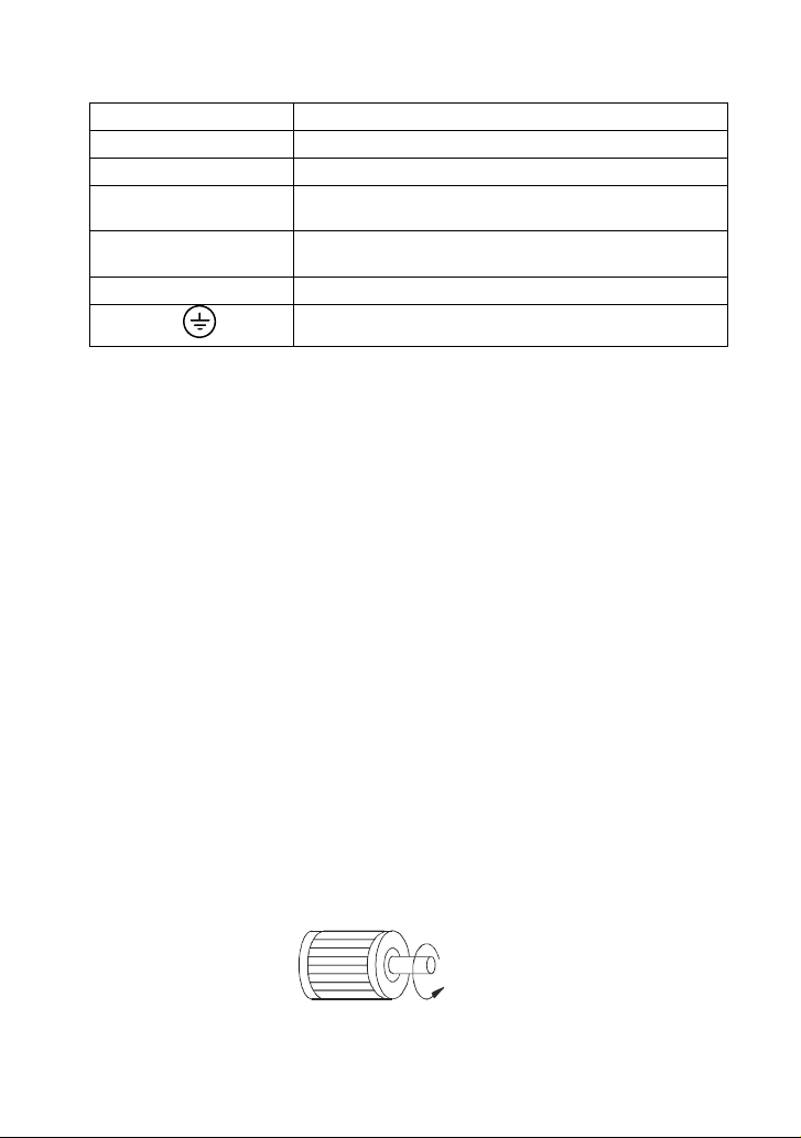
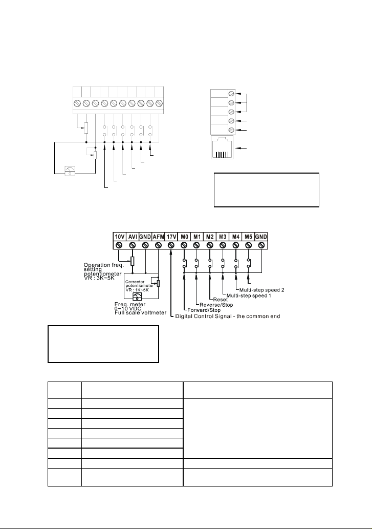
Control circuit terminals (U/T1, V/T2, W/T3)
When the AC drive output terminals U/T1, V/T2, and W/T3 are connected to the motor
terminals U, V, and W, respectively, the motor will rotate counterclockwise (as viewed on
the shaft end of the motor) when a forward operation command is received. To
permanently reverse the direction of motor rotation, switch over any of the two motor
leads.
AC drive output terminals for connecting 3-phase induction
motor
Connections for DC choke. Please remove the
installation.
Earth connection, please comply with local regulations.
Forward
running
umper prior to
Revision August 2008, SE09, SW V2.61 2-23
Page 39
Chapter 2 Installation and Wiring|VFD-S Series
)
DO NOT connect phase-compensation capacitors or surge absorbers at the output
terminals of AC motor drives.
With long motor cables, high capacitive switching current peaks can cause over-current,
high leakage current or lower current readout accuracy. To prevent this, the motor cable
should be less than 20m for 3.7kW models and below. And the cable should be less than
50m for 5.5kW models and above. For longer motor cables use an AC output reactor.
Use a well-insulated motor, suitable for inverter operation.
Terminals [+2/B1, +1] for connecting DC reactor
This is the connector for the DC reactor to improve the power factor. Please remove the
short jumper when connecting DC reactor.
Terminals [+2/B1, B2] for connecting brake resistor
Bra ke resistor(o ptiona l
Ref er to Append ix B for the use of
spec ial brake resis tor.
BR
Connect a brake resistor in applications with frequent deceleration ramps, short
+2 /B1
B2
deceleration time, too low brake torque or requiring increased brake torque.
WARNI NG !
Short-circuiting [+2/B1, B2] can damage the AC motor drive.
Grounding terminals (
Make sure that the leads are connected correctly and the AC drive is properly grounded.
)
(Ground resistance should not exceed 0.1Ω.)
Use ground leads that comply with local regulations and keep them as short as possible.
Multiple VFD-S units can be installed in one location. All the units should be grounded
directly to a common ground terminal, as shown in the figure below. Ensure there are
no ground loops.
goodexcellent
not allowed
2-24 Revision August 2008, SE09, SW V2.61
Page 40
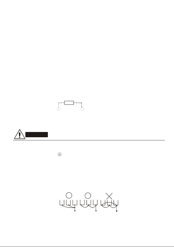
2.4.4 Control Terminals
*
*
Control Terminal Wiring (Factory Setting)
A. XXXSXXA/B/D/U
+
AFM
AVI
M0M4M2 M3M5GND
10V
Operation freq.
setting
potentiometer
VR : 3K~5K
Corrector
potentiometer
VR : 1K~5K
Freq. meter
0~10 VDC
Full scale voltmeter
B. XXXSXXE
M1
Multi-step speed 1
Reset
Reverse/Stop
Forward/Stop
Multi-step speed 3
Multi-step speed 2
Chapter 2 Installation and Wiring|VFD-S Series
RA
RB
RC
MO1
MCM
RJ11
Relay contactor output
Factory setting : Fault indication
Photo coupler output
Factory setting : in work
RS485 Communication port
6 ~ 1
Wire Gauge: 24-12 AWG
Wire Type: Copper Only
Torque: 4 kgf-cm (3.5 in-lbf)
Multi-step speed 3
Wire Gauge: 24-16 AWG
Wire Type: Copper Only
Torque: 2 kgf-cm (1.7 in-lbf)
Terminal symbols and functions
Terminal
Symbol
Terminal Function
Factory Settings (NPN mode)
ON: Connect to GND
M0 Multi-function auxiliary input
M1 Multi-function input 1
M2 Multi-function input 2
M3 Multi-function input 3
M4 Multi-function input 4
Refer to Pr.4-04 to Pr.4-08 for programming
the Multi-function Inputs.
ON: the activation current is 16mA.
OFF: leakage current tolerance is 10μA.
M5 Multi-function Input 5
+17V DC Voltage Source +17VDC, 20mA used for PNP mode.
GND Digital Signal Common
Revision August 2008, SE09, SW V2.61 2-25
Common for digital inputs and used for NPN
mode.
Page 41
Chapter 2 Installation and Wiring|VFD-S Series
A
A
A
Terminal
Symbol
Terminal Function
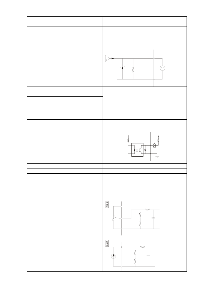
AFM Analog output meter
Factory Settings (NPN mode)
ON: Connect to GND
The voltage output type for this analog
signal is PWM, so this analog voltage is
only suitable to connect an external
movable coil meter, not suitable to connect
a digital meter or for A/D signal conversion.
AFM circuit
FM
0~10V
ondometer
Max. 2mA
GND
Multi-function Relay output
RA
(N.O.) a
Multi-function Relay output
RB
(N.C.) b
RC Multi-function Relay common
Internal Circuit
Resistive Load:
5A(N.O.)/3A(N.C.) 240VAC
5A(N.O.)/3A(N.C.) 24VDC
Inductive Load:
1.5A(N.O.)/0.5A(N.C.) 240VAC
1.5A(N.O.)/0.5A(N.C.) 24VDC
Refer to Pr.3-06 for programming
Maximum 48VDC, 50mA
Multi-function Output 1
MO1
(Photocoupler)
Refer to Pr.3-01 for programming
MO1-DCM
internal circuit
MO1
MCM
Max: 48Vdc
50mA
MCM Multi-function output common Max. 48Vdc 50mA
+10V Potentiometer power supply +10VDC 10mA (variable resistor: 3~5kohm)
0~+10V/4-20mA corresponds to 0-max.
operation frequency (Pr.01-00)
PID feedback signal
AVI input impedance: 47kohm
ACI input impedance: 250kohm
Analog voltage Input
AVI
(AVI/ACI)
AVI
ACI
J1
AVI
ACI
J1
+10V
VI
GND
CI
AVI c ircu it
Internal Circuit
ACI circuit
GND
Internal Circuit
Control signal wiring size: 18 AWG (0.75 mm2) with shielded wire.
2-26 Revision August 2008, SE09, SW V2.61
Page 42

Chapter 2 Installation and Wiring|VFD-S Series
A
Analog input terminals (AVI, GND)
Analog input signals are easily affected by external noise. Use shielded wiring and keep
it as short as possible (<20m) with proper grounding. If the noise is inductive, connecting
the shield to terminal GND can bring improvement.
If the analog input signals are affected by noise from the AC motor drive, please connect
a capacitor (0.1μF and above) and ferrite core as indicated in the following diagrams:
C
ferrite core
wind each wires 3 times or more around the core
VI
GND
Digital inputs (M0~M5, GND)
When using contacts or switches to control the digital inputs, please use high quality
components to avoid contact bounce.
Digital outputs (MO1, MCM)
Make sure to connect the digital outputs to the right polarity, see wiring diagrams.
When connecting a relay to the digital outputs, connect a surge absorber or fly-back
diode across the coil and check the polarity.
General
Keep control wiring as far as possible from the power wiring and in separate conduits to
avoid interference. If necessary let them cross only at 90º angle.
The AC motor drive control wiring should be properly installed and not touch any live
power wiring or terminals.
NOTE
If a filter is required for reducing EMI (Electro Magnetic Interference), install it as close as
possible to AC drive. EMI can also be reduced by lowering the Carrier Frequency.
When using a general GFCI (Ground Fault Circuit Interrupter), select a current sensor
with sensitivity of 200mA or above, and not less than 0.1-second detection time to avoid
nuisance tripping. For the specific GFCI of the AC motor drive, please select a current
sensor with sensitivity of 30mA or above.
DANGER!
Damaged insulation of wiring may cause personal injury or damage to circuits/equipment if it comes
in contact with high voltage.
Revision August 2008, SE09, SW V2.61 2-27
Page 43
Chapter 2 Installation and Wiring|VFD-S Series
2.4.5 Main Circuit Terminals
VFD002S11A/11B, VFD004S11A/11B
Power terminal
AC Input Line
Terminal
Motor
Connection
Ground Brake Resistor
Power Terminal:
Torque: 12 kgf-cm (10 lbf-in)
Wire Gauge: 14-20 AWG (2.1-0.5mm
Wire Type: Copper only, 75
2-28 Revision August 2008, SE09, SW V2.61
o
2
)
C
Page 44

Chapter 2 Installation and Wiring|VFD-S Series
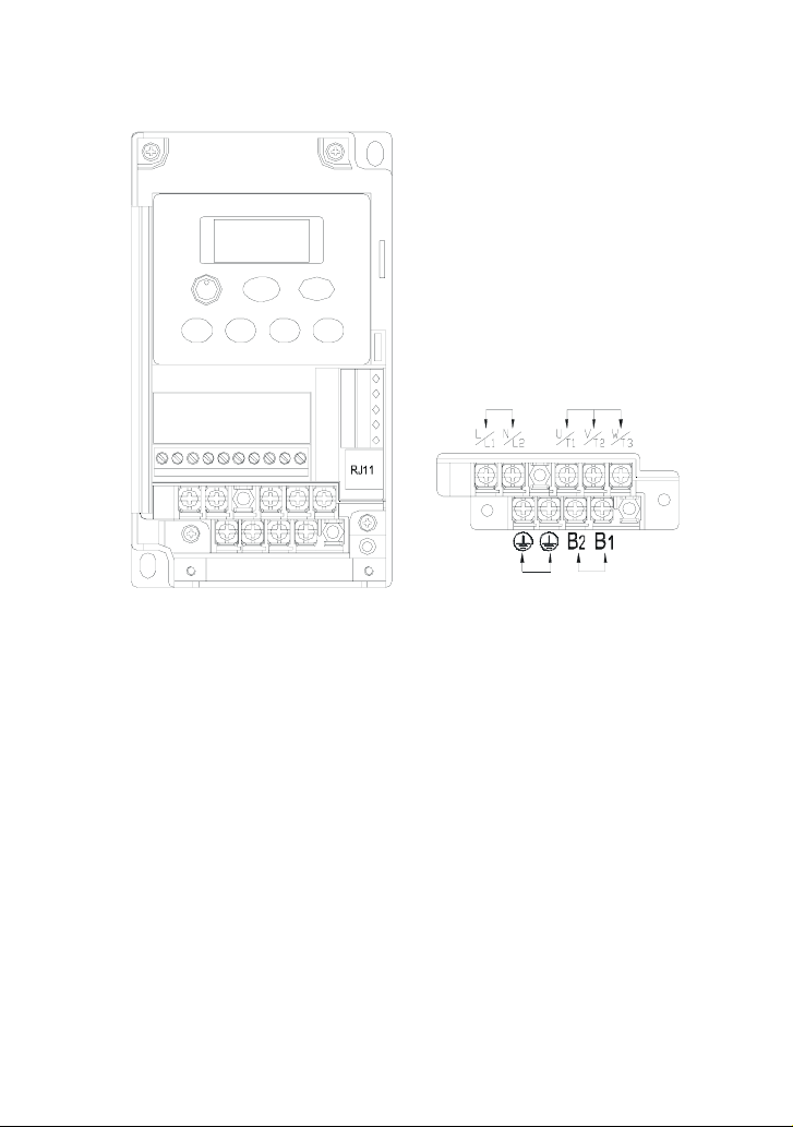
VFD002S21B/23A, VFD004S21B/23A/43A/43B/43E, VFD007S21B/23A/43A/43B/43E,
VFD015S23D
Power terminal
Power Terminal:
Torque: 12 kgf-cm (10 lbf-in)
Wire Gauge: 14-20 AWG (2.1-0.5mm
Wire Type: Copper only, 75
o
C
AC Input Line
Ter min al
2
)
Motor
Connection
Ground DC ReactorBrak e
Resistor
Revision August 2008, SE09, SW V2.61 2-29
Page 45

Chapter 2 Installation and Wiring|VFD-S Series
VFD002S21A/E, VFD004S21A/E, VFD007S21A/E
Power terminal
AC Input Line
Ter min al
Motor
Connection
Ground
Brak e
Resistor
DC Reactor
Power Terminal:
Torque: 12 kgf-cm (10 lbf-in)
Wire Gauge: 14-20 AWG (2.1-0.5mm
Wire Type: Copper only, 75
2-30 Revision August 2008, SE09, SW V2.61
o
2
)
C
Page 46

VFD007S11A/B
Power Terminal:
Torque: 20 kgf-cm (17.4 lbf-in)
Wire Gauge: 10-18 AWG (5.3-0.8mm
Wire Type: stranded copper only, 75
Chapter 2 Installation and Wiring|VFD-S Series
Power terminal
AC Input Line
Terminal
Ground
2
)
o
C
M otor
Conne ction
Brake Resist or
Revision August 2008, SE09, SW V2.61 2-31
Page 47

Chapter 2 Installation and Wiring|VFD-S Series
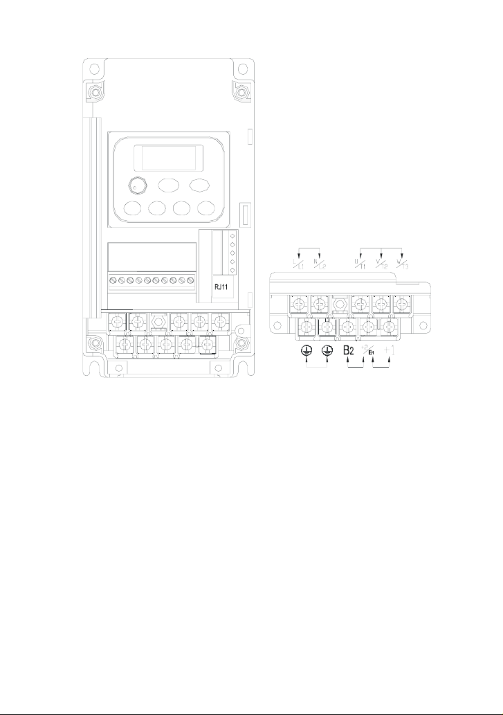
VFD015S21U/43D/43E/43U, VFD022S21U/23D/43D/43E/43U
AC Input Line
Te rm in al
Power terminal
Motor
Connection
Ground
Resistor
DC ReactorBrak e
Power Terminal:
Torque: 20 kgf-cm (17.4 lbf-in)
Wire Gauge: 10-18 AWG (5.3-0.8mm
Wire Type: stranded copper only, 75
2-32 Revision August 2008, SE09, SW V2.61
2
)
o
C
Page 48
VFD015S21D/E, VFD022S21D/E
Power Terminal:
Torque: 20 kgf-cm (17.4 lbf-in)
Wire Gauge: 10-18 AWG (5.3-0.8mm
Wire Type: stranded copper only, 75
Chapter 2 Installation and Wiring|VFD-S Series
Power terminal
AC Input Line
Te rm in al
2
)
o
C
Brak e
Resistor
Motor
Connection
DC ReactorGround
Revision August 2008, SE09, SW V2.61 2-33
Page 49

Chapter 2 Installation and Wiring|VFD-S Series
This page intentionally left blank
2-34 Revision August 2008, SE09, SW V2.61
Page 50
Chapter 3 Start Up
3.1 Preparations before Start-up
Carefully check the following items before proceeding.
Make sure that the wiring is correct. In particular, check that the output terminals U/T1,
V/T2, W/T3 are NOT connected to power and that the drive is well grounded.
Verify that there are no short-circuits between terminals and from terminals to ground or
mains power.
Check for loose terminals, connectors or screws.
Verify that no other equipment is connected to the AC motor.
Make sure that all switches are OFF before applying power to ensure that the AC motor
drive doesn’t start running and there is no abnormal operation after applying power.
Make sure that the front cover is correctly installed before applying power.
Do NOT operate the AC motor drive with humid hands.
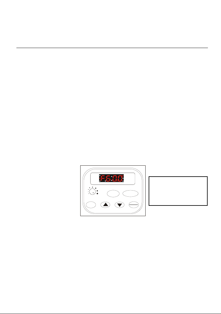
Check the following items after applying power: The display without digital keypad should
be as following.
-The keypad should light up as follows (normal status with no error)
RUN
FWD
REV
STOP
When power is ON,
LEDs “STOP” and “FWD”
STOP/RESET
MIN. MAX.
MODE
RUN
PROG
DATA
- If the drive has built-in fan, it should run.
Revision August 2008, SE09, SW V2.61 3-1
should light up. The
display will show “F60.0”.
Page 51
Chapter 3 Start Up| VFD-S Series
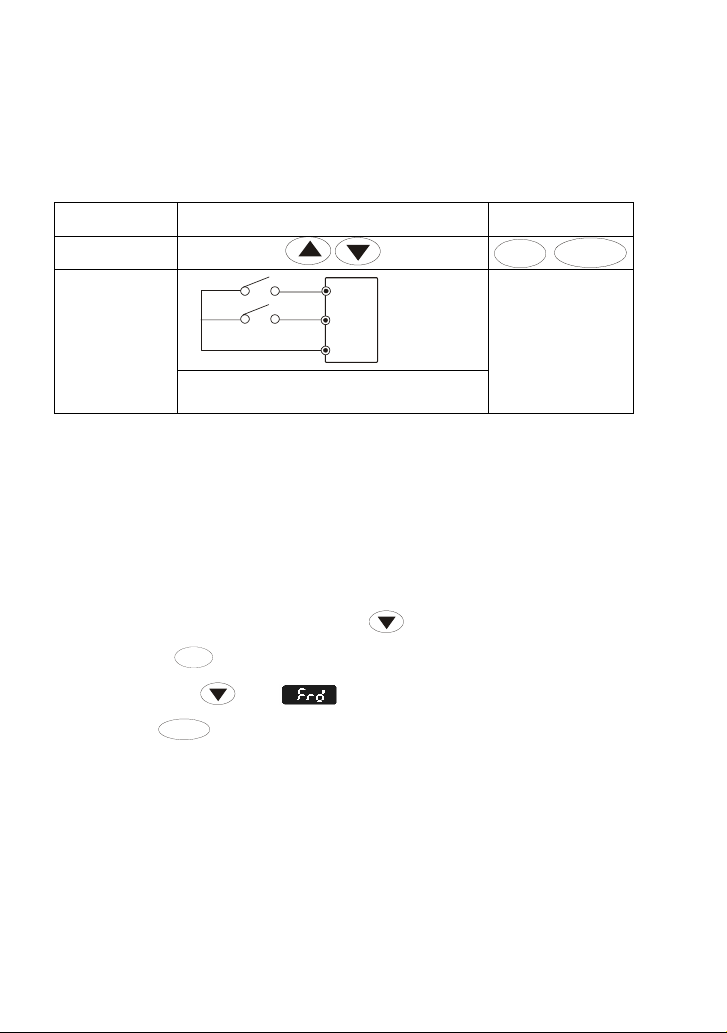
3.2 Operation Method
Refer to 4.2 How to operate the digital keypad and chapter 5 parameters for setting. Please choose
a suitable method depending on application and operation rule. The operation is usually done as
shown in the following table.
Operation Method Frequency Source
Keypad
M2
Operate from
external signal
M3
GND
AVI, ACI
Parameter
setting:
4-05=15
4-06=16
Operation Command
Source
STOP/RESET
RUN
External terminals
input:
M0-GND
M1-GND
3.3 Trial Run
After finishing checking the items in “3.1 preparation before start-up”, you can perform a trial run.
1. After applying power, verify that the display shows “F60.0”.
2. Setting Pr.2-00 to d0, and setting Pr.2-01 to d0 as well. (Refer to Chapter 4 for the operation
of the digital keypad.)
3. Setting frequency to about 5Hz by using
4. Pressing
should press
press
5. Check following items:
If the results of trial run are normal, please start the formal run.
RUN
key for forward running. And if you want to change to reverse running, you
key in page. And if you want to decelerate to stop, please
STOP/RESET
key.
Check if the motor direction of rotation is correct.
Check if the motor runs steadily without abnormal noise and vibration.
Check if acceleration and deceleration are smooth.
key.
3-2 Revision August 2008, SE09, SW V2.61
Page 52

Chapter 3 Start Up| VFD-S Series
NOTE
1. Stop running immediately if any fault occurs and refer to the troubleshooting guide for solving the
problem.
2. Do NOT touch output terminals U/T1, V/T2, W/T3 when power is still applied to R/L1, S/L2, T/L3
even when the AC motor drive has stopped. The DC-link capacitors may still be charged to
hazardous voltage levels, even if the power has been turned off.
3. To avoid damage to components, do not touch them or the circuit boards with metal objects or
your bare hands.
Revision August 2008, SE09, SW V2.61 3-3
Page 53

Chapter 3 Start Up| VFD-S Series
This page intentionally left blank
3-4 Revision August 2008, SE09, SW V2.61
Page 54
Chapter 4 Digital Keypad Operation
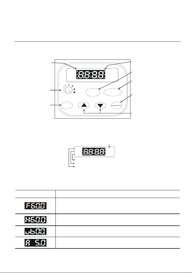
4.1 Description of the Digital Keypad
LED indication
Light during RUN,
STOP, FWD and
REV operation.
Potentiometer for
frequenc y setting.
Could be the Master
Frequency input
by setting Pr.2-00.
Mode Key
Change between
different display
modes.
4.2 Explanation of LED Indicators
RUN
FWD
REV
MIN. MAX.
RUN
MODE
Stop AC drive when STOP
button has been pressed.
RUN
FWD
REV
REV LED lights during reverse operation.
FWD LED lights during forward operation.
RUN LED lights during RUN operatio n.
STOP/RESET
STOP
STOP
PROG
DATA
LED Display
Indicate frequency, motor
parameter setting value
and alarm contents.
RUN Key
Start inverter dr ive operation.
STOP/RESET Key
Stop inverte r drive operat ion
and reset the inverter after
faults occurred.
PROG/DATA Key
Set the different parameters
and enter information.
UP and DOWN Key
Sets the parameter number
or changes the numeri cal
data such as the freq.
reference.
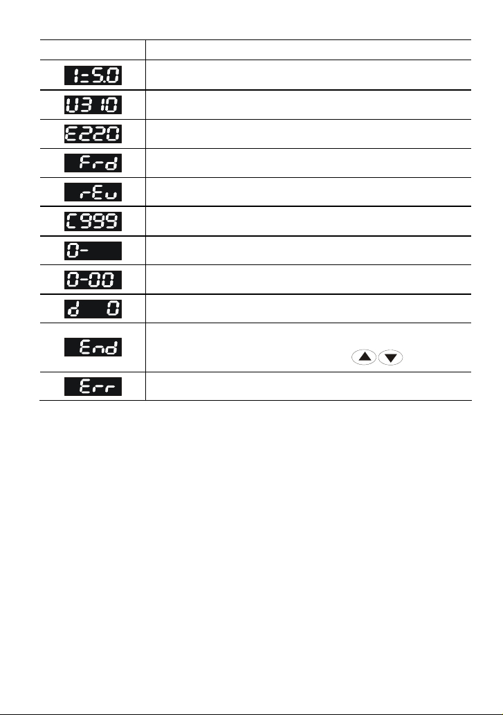
4.3 Explanations of Display Messages
Display Message Descriptions
Displays the AC drive Master Frequency.
Displays the actual output frequency at terminals U/T1, V/T2, and W/T3.
User defined unit (where U = F x Pr.0-05)
Displays the output current at terminals U/T1, V/T2, and W/T3.
Revision August 2008, SE09, SW V2.61 4-1
Page 55
Chapter 4 Digital Keypad Operation|VFD-S Series
Display Message Descriptions
The internal PLC process step currently being performed.
Displays the DC-BUS voltage
Displays the output voltage
Displays the AC motor drive forward run status.
Displays the AC motor drive reverse run status.
The counter value (C).
Displays the selected group.
Displays the selected parameter.
Displays the actual stored value of the selected parameter.
Display “End” for approximately one second if input has been accepted.
After a parameter value has been set, the new value is automatically
stored in memory. To modify an entry, use the
Display “Err”, if the input is invalid.
keys.
4-2 Revision August 2008, SE09, SW V2.61
Page 56
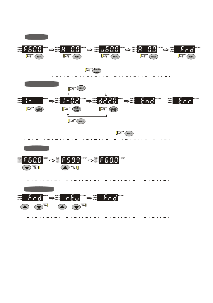
4.4 How to Operate the Digital Keypad
Setting Mode
START
Chapter 4 Digital Keypad Operation|VFD-S Series
In the selection mode, press
Note
:
Setting parameters
:
NOTE
In the parameter setting mode, you can press
To s hi ft da ta
START
Setting direction
or
(When operation source is digital keypad)
or
to set the parameters.
move down to the previous display
Success to
set parameter.
move up to the previous display
to return the selecting mode.
GO START
or
Input data error
Revision August 2008, SE09, SW V2.61 4-3
Page 57

Chapter 4 Digital Keypad Operation|VFD-S Series
This page intentionally left blank
4-4 Revision August 2008, SE09, SW V2.61
Page 58

Chapter 5 Parameters
The VFD-S parameters are divided into 11 groups by property for easy setting. In most applications,
the user can finish all parameter settings before start-up without the need for re-adjustment during
operation.
The 11 groups are as follows:
Group 0: User Parameters
Group 1: Basic Parameters
Group 2: Operation Method Parameters
Group 3: Output Function Parameters
Group 4: Input Function Parameters
Group 5: Multi-Step Speed and PLC Parameters
Group 6: Protection Parameters
Group 7: Motor Parameters
Group 8: Special Parameters
Group 9: Communication Parameters
Group A: PID Parameters
Revision August 2008, SE09, SW V2.61 5-1
Page 59

Chapter 5 Parameters|VFD-S Series
5.1 Summary of Parameter Settings
: The parameter can be set during operation.
Group 0 User Parameters
Pr. Explanation Settings
0-00 Identity Code of the AC Motor Drive Read-only d #
0-01 Rated Current Display of the AC
Read-only d##.#
Motor Drive
0-02 Parameter Reset d09: All parameters are reset to
factory settings (50Hz,
220V/380V)
d10: All parameters are reset to
factory settings (60Hz,
220V/440V)
d0: Display the frequency command
value (LED F)
d1: Display the actual output
frequency (LED H)
0-03 Start-up Display Selection
d2: Multifunction display, see Pr.00-
04
d3: Display output current (LED A)
d4: Display forward/reverse
command (Frd/rEv)
d0: Display User-Defined Unit (u)
d1: Display Counter Value (C)
d2: Display Process Operation (1.tt)
d3: Display DC-BUS Voltage (
0-04 Content of Multi-Function Display
d4: Display output voltage (E)
d5: Display frequency commands of
PID (P)
d6: Display analog feedback signal
value (b) (%)
d7: Display output voltage
command (G)
0-05 User-Defined Coefficient K d0.1 to d160 d1.0
0-06 Software Version Read-only d#.#
0-07 Password Input d0 to d999 d0
0-08 Password Set d0 to d999 d0
0-09 Memory Mode Selections d0 to d63 d8
Group 1 Basic Parameters
Pr. Explanation Settings
1-00 Maximum Output Frequency (Fmax) d50.0 to d400 Hz d60.0
1-01 Maximum Voltage Frequency (Fbase) d10.0 to d400 Hz d60.0
1-02 Maximum Output Voltage (Vmax)
230V series: d2.0V to d255V d220
460V series: d4.0V to d510V d440
1-03 Mid-Point Frequency (Fmid) d1.0 to d400 Hz d1.0
Factory
Setting
d0
d0
u
)
d0
Factory
Setting
NOTE
NOTE
5-2 Revision August 2008, SE09, SW V2.61
Page 60

Chapter 5 Parameters|VFD-S Series
Pr. Explanation Settings
1-04 Mid-Point Voltage (Vmid)
230V series: d2.0V to d255V d12
460V series: d4.0V to d510V d24
Factory
Setting
1-05 Minimum Output Frequency (Fmin) d1.0 to d60.0 Hz d1.0
1-06 Minimum Output Voltage (Vmin)
230V series: d2.0V to d255V d12.0
460V series: d4.0V to d510V d24.0
1-07 Output Frequency Upper Limit d1 to d110% d100
1-08 Output Frequency Lower Limit d0 to d100% d0
1-09 Accel Time 1 d0.1 to d600 Sec d10.0
1-10 Decel Time 1 d0.1 to d600 Sec d10.0
1-11 Accel Time 2 d0.1 to d600 Sec d10.0
1-12 Decel Time 2 d0.1 to d600 Sec d10.0
1-13 Jog Acceleration / Deceleration Time d0.1 to d600 Sec d10.0
1-14 Jog Frequency d1.0 Hz to d400 Hz d6.0
d0: Linear Accel/Decel
d1: Auto Accel, Linear Decel
d2: Linear Accel, Auto Decel
Auto acceleration / deceleration (refer
1-15
to Accel/Decel time setting)
d3: Auto Accel/Decel (Set by load)
d4: Linear Accel; Auto Decel, Stall
Prevention during Decel
d0
d5: Auto Accel/Decel, Stall
Prevention during Decel
1-16 Acceleration S-Curve d0 to d7 d0
1-17 Deceleration S-Curve d0 to d7 d0
d0.0 Jog Decelerating Time
1-18 Jog Decelerating Time
Determined by Pr.1-13
d0.0
d0.1 to d600
Group 2 Operation Method Parameters
Pr. Explanation Settings
Factory
Setting
d0: Master Frequency input
determined by digital keypad.
(record the frequency of power
loss and it can do analog
overlap plus)
d1: Master Frequency determined
by analog signal DC 0V-10V
(external terminal AVI). (won’t
Source of Master Frequency
2-00
Command
record the frequency of power
loss and it can’t do analog
d0
overlap plus)
d2: Master Frequency determined
by analog signal DC 4mA -
20mA (external terminal AVI).
(won’t record the frequency of
power loss and it can’t do
analog overlap plus)
NOTE
NOTE
Revision August 2008, SE09, SW V2.61 5-3
Page 61

Chapter 5 Parameters|VFD-S Series
Pr. Explanation Settings
d3: Master Frequency determined
by Potentiometer on the digital
keypad. (won’t record the
frequency of power loss and it
can do analog overlap plus)
d4: Master Frequency operated by
RS-485 serial communication
interface and record frequency
Source of Master Frequency
2-00
Command
of power loss. (record the
frequency of power loss and it
can do analog overlap plus)
d5: Master Frequency operated by
RS-485 serial communication
interface and won’t record
frequency before power loss.
(won’t record the frequency of
power loss and it can do analog
overlap plus)
d0: Digital Keypad
d1: External terminals. Keypad
STOP/RESET enabled.
d2: External terminals. Keypad
Source of Operation
2-01
Command
STOP/RESET disabled.
d3: RS-485 serial communication
(RJ-11) .Keypad STOP/RESET
enabled.
d4: RS-485 serial communication
(RJ-11). Keypad STOP/RESET
disabled.
d0: STOP: ramp to stop; E.F.: coast
2-02 Stop Method
to stop
d1: STOP: coast to stop; E.F.: coast
to stop
d3: 3KHz
d4: 4KHz
d5: 5KHz
2-03 PWM Carrier Frequency Selections
d6: 6KHz
d7: 7KHz
d8: 8KHz
d9: 9KHz
d10: 10KHz
d0: Enable forward/reverse
2-04 Motor Direction Control
operation
d1: Disable reverse operation
d0: Decelerate to 0 Hz
2-05 Loss of ACI Signal
d1: Coast to stop and display “EF”
d2: Continue operation by last
frequency command
d0: Disable
2-06 Analog Auxiliary Frequency Operation
d1: Enable + AVI
d2: Enable + ACI
Factory
Setting
d0
d0
d0
d10
d0
d0
d0
NOTE
5-4 Revision August 2008, SE09, SW V2.61
Page 62

Chapter 5 Parameters|VFD-S Series
Group 3 Output Function Parameters
Pr. Explanation Settings
3-00 Analog Output Signal
d0: analog frequency meter
d1: analog current meter
Factory
Setting
d0
3-01 Analog Output Gain d1 to d200% d100
3-02 Desired Frequency Attained d1.0 to d400 Hz d1.0
3-03 Terminal Count Value d0 to d999 d0
3-04 Preliminary Count Value d0 to d999 d0
Multi-Function Output Terminal 1
3-05
(Photocoupler Output)
d0: No Function d1
d1: AC Drive Operational
d2: Master Frequency Attained
d3: Zero Speed
d4: Over Torque Detection
d5: Base-Block (B.B.) Indication
d6: Low-Voltage Indication
d7: Operation Mode Indication
d8: Fault Indication
Multi-Function Output Terminal 2
3-06
(Relay Output)
d9: Desired Frequency Attained
d10: PLC Program Running
d11: PLC Program Step Completed
d8
d12: PLC Program Completed
d13: PLC Program Operation
Paused
d14: Terminal Count Value Attained
d15: Preliminary Count Value
Attained
d16: AC Motor Drive Ready
d17: FWD command Indication
d18: REV command Indication
Group 4 Input Function Parameters
Pr. Explanation Settings
Factory
Setting
4-00 Potentiometer Bias Frequency d 0.0 to d 100.0% d0.0
Potentiometer Bias
4-01
Polarity
Potentiometer
4-02
Frequency Gain
Potentiometer Reverse
4-03
Motion Enable
d0: Positive Bias
d1: Negative Bias
d0
d1 to d200 % d100
d0: Forward Motion Only
d1: Reverse Motion enabled
d0
NOTE
NOTE
Revision August 2008, SE09, SW V2.61 5-5
Page 63

Chapter 5 Parameters|VFD-S Series
Pr. Explanation Settings
d0: No Function
Factory
Setting
NOTE
d1: FWD/STOP, REV/STOP
d2: FWD/REV, RUN/STOP
Multi-Function Input Terminal 1 (M0,
4-04
M1)
d3: 3-wire Operation Control Mode
d4: E.F. External Fault Input (N.O.)
d5: E.F. External Fault Input (N.C.)
d1
d6: Reset
d7: Multi-Step Speed Command 1
d8: Multi-Step Speed Command 2
d9: Multi-Step Speed Command 3
4-05 Multi-Function Input Terminal 2 (M2)
d10: Jog Operation
d11: Accel/decel Inhibit
d12: First or Second
d6
Acceleration/deceleration Time
4-06 Multi-Function Input Terminal 3 (M3)
Selection
d7
d13: External base block (N.O.)
d14: External base block (N.C.)
4-07 Multi-Function Input Terminal 4 (M4)
d15: Up: Increment master
frequency
d16: Down: Decrement master
d8
frequency
d17: Run PLC Program
d18: Pause PLC Program
d19: Counter Trigger Signal
d20: Counter Reset
d21: Select ACI / Deselect AVI
d22: PID Function Disabled
d23: JOG FWD
d24: JOG REV
d25: The source of master
4-08 Multi-Function Input Terminal 5 (M5)
frequency is AVI.
d26: The source of master
d9
frequency is ACI.
d27: Press UP/DOWN key to switch
forward/reverse (N.O.) motion
d28: Press UP/DOWN key to switch
forward/reverse (N.C.) motion
d29: M0: 0: RUN 1: STOP, M1: no
function, Direction is controlled
by keypad
4-09 Line Start Lockout
d0: Disable
d1: Enable
d0: Based on accel/decel time
d0
d1: Up frequency according to
constant speed, down frequency
according to deceleration time
4-10 Up/Down Mode
d2: Up frequency according to
d3
acceleration time, down
frequenc according to constant
speed
d3: Constant speed
Accel/Decel Rate of Change of
4-11
UP/DOWN Operation with Constant
0~1000, unit: 5 Hz/sec d1
Speed
5-6 Revision August 2008, SE09, SW V2.61
Page 64
Chapter 5 Parameters|VFD-S Series
Group 5 Multi-Step Speed and PLC Parameters
Pr. Explanation Settings
Factory
Setting
5-00 1st Step Speed Freq. d0.0 to d400 Hz d0.0
5-01 2nd Step Speed Freq. d0.0 to d400 Hz d0.0
5-02 3rd Step Speed Freq. d0.0 to d400 Hz d0.0
5-03 4th Step Speed Freq. d0.0 to d400 Hz d0.0
5-04 5th Step Speed Freq. d0.0 to d400 Hz d0.0
5-05 6th Step Speed Freq. d0.0 to d400 Hz d0.0
5-06 7th Step Speed Freq. d0.0 to d400 Hz d0.0
d0: Disable PLC Operation
d1: Execute one program cycle
d2: Continuously execute program
cycles
d3: Execute one program cycle step
5-07 PLC Mode
by step
d4: Continuously execute one
d0
program cycle step by step
d5: Disable PLC operation, but can
set direction of 1st speed to 7th
speed
5-08 PLC Forward/ Reverse Motion d0 to d255 (0: FWD 1: REV) d0
5-09 Time Duration of Master Speed d0 to d65500 Sec d0
5-10 Time Duration of 1st Step Speed d0 to d65500 Sec d0
5-11 Time Duration of 2nd Step Speed d0 to d65500 Sec d0
5-12 Time Duration of 3rd Step Speed d0 to d65500 Sec d0
5-13 Time Duration of 4th Step Speed d0 to d65500 Sec d0
5-14 Time Duration of 5th Step Speed d0 to d65500 Sec d0
5-15 Time Duration of 6th Step Speed d0 to d65500 Sec d0
5-16 Time Duration of 7th Step Speed d0 to d65500 Sec d0
Group 6 Protection Parameters
Pr. Explanation Settings
6-00 Over-Voltage Stall Prevention
Over-Voltage Stall Prevention Level
6-01
d0: Disable
d1: Enable
115V/230V series: d350 to d410V d390
460V series: d700 to d820V d780
Factory
Setting
d1
6-02 Over-Current Stall Prevention Level d20 to d150% d130
6-03 Over-Torque Detection Mode
d0: Disabled
d0
d1: Enabled during constant speed
operation. After the over-torque
is detected, keep running until
OL1 or OL occurs.
d2: Enabled during constant speed
operation. After the over-torque
is detected, stop running.
d3: Enabled during running and
continues before Continuous
Output Time Limit (Pr.6-05) is
reached.
NOTE
NOTE
Revision August 2008, SE09, SW V2.61 5-7
Page 65
Chapter 5 Parameters|VFD-S Series
Pr. Explanation Settings
Factory
Setting
NOTE
d4: Enabled during running. After
the over-torque is detected, stop
running.
6-04 Over-Torque Detection Level d30 to d200% d150
6-05 Over-Torque Detection Time d0.1 to d10.0 Sec d0.1
Electronic Thermal Overload Relay
6-06
Selection
Electronic Thermal
6-07
Characteristic
d0 to d2 d2
d30 to d600 Sec d60
d0: No fault
d1: Over current (oc)
6-08 Present Fault Record
d2: Over voltage (ov)
d3: Over heat (oH)
d4: Over load (oL)
d5: Over load (oL1)
6-09 Second Most Recent Fault Record
d6: External fault (EF)
d7: Reserved
d8: Reserved
d0
d9: Excess current during
acceleration (ocA)
6-10 Third Most Recent Fault Record
d10: Excess current during
deceleration (ocd)
d11: Excess current during steady
state (ocn)
d13: Reserved
d12: Ground fault (GF)
d14: Low voltage (Lv)
d15: CPU failure 1 (cF1)
d16: CPU failure 2 (cF2)
d17: Base block (b.b.)
d18: Overload (oL2)
d19: Auto acceleration/deceleration
failure (cFA)
d20: Software protection enable
(codE)
d21: Reserved
d22: CPU failure (cF3.1)
d23: CPU failure (cF3.2)
d24: CPU failure (cF3.3)
d25: CPU failure (cF3.4)
d26: CPU failure (cF3.5)
d27: CPU failure (cF3.6)
d28: CPU failure (cF3.7)
d29: Hardware protection failure
(HPF.1)
d30: Hardware protection failure
(HPF.2)
d31: Hardware protection failure
(HPF.3)
d32: Communication time-out
(CE10)
d33: Reserved
d34: Software error (SErr)
5-8 Revision August 2008, SE09, SW V2.61
Page 66
Chapter 5 Parameters|VFD-S Series
Pr. Explanation Settings
Factory
Setting
d35: Reserved
d36: PID error (Pld)
d37: Reserved
d38: Phase loss (PHL)
Group 7 Motor Parameters
Pr. Explanation Settings
Factory
Setting
7-00 Motor Rated Current d30 to d120% d85
7-01 Motor No-Load Current d0 to d90% d50
7-02 Torque Compensation d0 to d10 d1
7-03 Slip Compensation d0.0 to d10.0 d0.0
Group 8 Special Parameters
Pr. Explanation Settings
Factory
Setting
8-00 DC Brake Voltage Level d0 to d30% d0
8-01 DC Brake Time during Start-Up d0.0 to d60.0 Sec d0.0
8-02 DC Brake time during Stopping d0.0 to d60.0 Sec d0.0
8-03 Start-Point for DC Brake d0.0 to d400 Hz d0.0
d0: Operation stops after
Momentary Power Loss
d1: Operation continues after
Momentary Power Loss Operation
8-04
Selection
momentary power loss, speed
search starts with the Master
Frequency reference value
d0
d2: Operation continues after
momentary power loss, speed
search starts with the minimum
frequency
8-05 Maximum Allowable Power Loss Time d0.3 to d5.0 Sec d2.0
8-06 B.B. Time for Speed Search d0.3 to d5.0 Sec d0.5
8-07 Current Limit for Speed Search d30 to d200% d150
8-08 Skip Frequency 1 Upper Limit d0.0 to d400 Hz d0.0
8-09 Skip Frequency 1 Lower Limit d0.0 to d400 Hz d0.0
8-10 Skip Frequency 2 Upper Limit d0.0 to d400 Hz d0.0
8-11 Skip Frequency 2 Lower Limit d0.0 to d400 Hz d0.0
8-12 Skip Frequency 3 Upper Limit d0.0 to d400 Hz d0.0
8-13 Skip Frequency 3 Lower Limit d0.0 to d400 Hz d0.0
8-14 Auto Restart After Fault d0 to d10 d0
d0: Enable
8-15 AVR Function
d1: Disable
d2
d2: Disable when deceleration
Software Brake Level
8-16
115V/230V series: d350 to d450V d380
460V series: d700 to d900V d760
8-17 DC Brake Lower Bound Limit d0.0 to d400 Hz d0.0
NOTE
NOTE
NOTE
Revision August 2008, SE09, SW V2.61 5-9
Page 67
Chapter 5 Parameters|VFD-S Series
Group 9 Communication Parameters
Pr. Explanation Settings
9-00
Communication
Address
d1 to d254 d1
Factory
Setting
d0: Baud Rate 4800 bps
9-01 Transmission Speed
d1: Baud Rate 9600 bps
d2: Baud Rate 19200 bps
d1
d3: Baud Rate 38400 bps
d0: Warn and Keep Operating
Transmission Fault
9-02
Treatment
d1: Warn and Ramp to Stop
d2: Warn and Coast to Stop
d0
d3: Keep Operating without Warning
d0: Disable
9-03 Time-out Detection
d1 to d20: time setting (1 sec
d0
increment)
d0: 7,N,2 (Modbus, ASCII)
d1: 7,E,1 (Modbus, ASCII)
d2: 7,O,1 (Modbus, ASCII)
9-04
Communication
Protocol
d3: 8,N,2 (Modbus, ASCII)
d4: 8,E,1 (Modbus, ASCII)
d5: 8,O,1 (Modbus, ASCII)
d0
d6: 8,N,2 (Modbus, RTU)
d7: 8,E,1 (Modbus, RTU)
d8: 8,O,1 (Modbus, RTU)
Group A PID Parameters
Pr. Explanation Settings
Factory
Setting
d0: Disable PID function
d1: Negative PID feedback from
external terminal (AVI) 0 to
+10V
d2: Negative PID feedback from
external terminal (ACI) 4 to
A-00 Input terminal for PID Feedback
20mA
d0
d3: Positive PID feedback from
external terminal (AVI) 0 to
+10V
d4: Positive PID feedback from
external terminal (ACI) 4 to
20mA
A-01 Gain over PID Detection value d0 to d999 d100
A-02 Proportional Gain (P) d0 to d999 d100
A-03 Integral Time (I) d0 to d999 d100
A-04 Derivative Control (D) d0 to d100 d0
A-05 Upper Bound for Integral Control d0 to d100% d100
A-06 Primary Delay Filter Time d0 to d999 d0
A-07 PID Output Freq. Limit d0 to d110% d100
A-08 Feedback Signal Detection Time d0.0 to d650 seconds d0.0
NOTE
NOTE
5-10 Revision August 2008, SE09, SW V2.61
Page 68

Chapter 5 Parameters|VFD-S Series
Pr. Explanation Settings
Treatment of the Erroneous
A-09
Feedback Signals
d0: warn and RAMP to stop
d1: warn and COAST to stop
Factory
Setting
d0
A-10 Sleep Frequency d0.0 to d400Hz d0.0
A-11 Wakeup Frequency d0.0 to d400Hz d0.0
A-12 Sleep Period d0.0 to d650 seconds d0.0
A-13 PID User Defined d0.0 to d400 d0.0
NOTE
Revision August 2008, SE09, SW V2.61 5-11
Page 69

Chapter 5 Parameters|VFD-S Series
5.2 Parameter Settings for Applications
Speed Search
Applications Purpose Functions
Windmill, winding
machine, fan and all
inertia loads
DC Brake before Running
Applications Purpose Functions
When e.g. windmills,
fans and pumps rotate
freely by wind or flow
without applying power
Multi-step Operation
Applications Purpose Functions
Conveying machinery
Switching acceleration and deceleration times
Applications Purpose Functions
Auto turntable for
conveying machinery
Operation Command
Applications Purpose Functions
General application
Restart freerunning motor
Keep the freerunning motor at
standstill.
Cyclic operation by
multi-step speeds.
Switching
acceleration and
deceleration times
by external signal
Selecting the
source of control
signal
Before the free-running motor is
completely stopped, it can be restarted
without detection of motor speed. The
AC motor drive will auto search motor
speed and will accelerate when its
speed is the same as the motor speed.
If the running direction of the freerunning motor is not steady, please
execute DC brake before start-up.
To control 7-step speeds and duration
by simple contact signals.
When an AC motor drive drives two or
more motors, it can reach high-speed
but still start and stop smoothly.
Selection of AC motor drive control by
external terminals, digital keypad or
RS485.
Related
Parameters
8-06
8-07
Related
Parameters
8-00
8-01
8-17
Related
Parameters
4-04~4-08
5-00~5-06
Related
Parameters
1-09~1-12
4-04~4-08
Related
Parameters
2-01
4-04~4-08
5-12 Revision August 2008, SE09, SW V2.61
Page 70
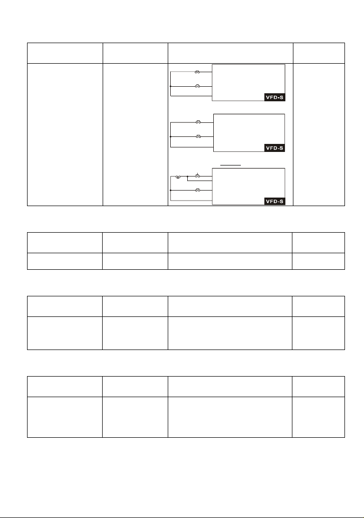
Chapter 5 Parameters|VFD-S Series
Two-wire/three-wire
Applications Purpose Functions
FWD/STOP
REV/STOP
M0 "Open": Stop, "Close": FWD Run
M1 "Open": Stop, "Close":REV Run
GND
M0 "Open": Stop, "Close": Run
M1 "Open": FWD, "Close":REV
REV/FWD
GND
3-wire
M0 Run command, Runs when "close"
M2 Stop command, stops when "Open"
M1 REV/FWD Run selection
"Open": FWD Run
REV/FWD
"Close": REV Run
GND
General application
To run, stop,
forward and
reverse by external
terminals
RUN/STOP
STOP RUN
Frequency Hold
Applications Purpose Functions
General application
Acceleration/
deceleration pause
Hold output frequency during
Acceleration/deceleration
Auto Restart after Fault
Applications Purpose Functions
Air conditioners,
remote pumps
For continuous and
reliable operation
without operator
intervention
The AC motor drive can be
restarted/reset automatically up to 10
times after a fault occurs.
Emergency Stop by DC Brake
Applications Purpose Functions
AC motor drive can use DC brake for
High-speed rotors
Emergency stop
without brake
resistor
emergency stop when quick stop is
needed without brake resistor. When
used often, take motor cooling into
consideration.
Related
Parameters
4-04~4-08
Related
Parameters
4-04~4-08
Related
Parameters
8-14
Related
Parameters
8-00
8-02
8-03
Revision August 2008, SE09, SW V2.61 5-13
Page 71

Chapter 5 Parameters|VFD-S Series
Over-torque Setting
Applications Purpose Functions
The over-torque detection level can be
set. Once OC stall, OV stall and overtorque occurs, the output frequency
will be adjusted automatically. It is
suitable for machines like fans and
pumps that require continuous
Pumps, fans and
extruders
To protect
machines and to
have continuous/
reliable operation
operation.
Upper/Lower Limit Frequency
Applications Purpose Functions
When user cannot provide
upper/lower limit, gain or bias from
external signal, it can be set
individually in AC motor drive.
Pump and fan
Control the motor
speed within
upper/lower limit
Skip Frequency Setting
Applications Purpose Functions
The AC motor drive cannot run at
Pumps and fans
To prevent
machine vibrations
constant speed in the skip frequency
range. Three skip frequency ranges
can be set.
Carrier Frequency Setting
Applications Purpose Functions
The carrier frequency can be
General application Low noise
increased when required to reduce
motor noise.
Keep Running when Frequency Command is Lost
Applications Purpose Functions
When the frequency command is lost
Air conditioners
For continuous
operation
by system malfunction, the AC motor
drive can still run. Suitable for
intelligent air conditioners.
Related
Parameters
6-03~6-05
Related
Parameters
1-07
1-08
Related
Parameters
8-08~8-13
Related
Parameters
2-03
Related
Parameters
2-05
5-14 Revision August 2008, SE09, SW V2.61
Page 72

Chapter 5 Parameters|VFD-S Series
Output Signal during Running
Applications Purpose Functions
Signal available to stop braking (brake
General application
Provide a signal for
running status
release) when the AC motor drive is
running. (This signal will disappear
when the AC motor drive is freerunning.)
Output Signal in Zero Speed
Applications Purpose Functions
When the output frequency is lower
General application
Provide a signal for
running status
than the min. output frequency, a
signal is given for external system or
control wiring.
Output Signal at Desired Frequency
Applications Purpose Functions
General application
Provide a signal for
running status
When the output frequency is at the
desired frequency, a signal is given for
external system or control wiring.
Over-torque Detection
Applications Purpose Functions
Pumps, fans and
extruders
To protect
machines and to
have continuous/
reliable operation
The over-torque detection level can be
set. Once over-torque occurs, a signal
will occur to prevent the AC motor
drive damage.
Output Signal at Low-voltage
Applications Purpose Functions
General application
Provide a signal for
running status
When the voltage between P-N is low
voltage, a signal is given for external
system or control wiring.
Related
Parameters
3-05~3-06
Related
Parameters
3-05~3-06
Related
Parameters
3-05~3-06
Related
Parameters
3-05~3-06
6-04
6-05
Related
Parameters
3-05~3-06
Revision August 2008, SE09, SW V2.61 5-15
Page 73

Chapter 5 Parameters|VFD-S Series
Output Signal when Frequency Attained
Applications Purpose Functions
When the output frequency is at the
General application
Provide a signal for
running status
desired frequency (by frequency
command), a signal is given for
external system or control wiring
(frequency attained).
Output Signal for Base Block
Applications Purpose Functions
General application
Provide a signal for
running status
When executing Base Block, a signal
is given for external system or control
wiring.
Overheat Warning for Heat Sink
Applications Purpose Functions
When heat sink is overheated, it will
General application For safety
send a signal for external system or
control wiring.
Multi-function Analog Output
Applications Purpose Functions
The value of frequency, output
General application
Display running
status
current/voltage can be read by
connecting a frequency meter or
voltage/current meter.
Related
Parameters
3-05~3-06
3-04
3-10
Related
Parameters
3-05~3-06
Related
Parameters
3-05~3-06
Related
Parameters
3-05
5-16 Revision August 2008, SE09, SW V2.61
Page 74

Chapter 5 Parameters|VFD-S Series
5.3 Description of Parameter Settings
Group 0: User Parameters This parameter can be set during operation.
0-00 Identity Code of the AC Motor Drive
Settings Read Only Factory setting: d#
0-01 Rated Current Display of the AC motor drive
Settings Read Only Factory setting: d ##.#
Pr. 0-00 displays the identity code of the AC motor drive. The capacity, rated current, rated
voltage and the max. carrier frequency relate to the identity code. Users can use the following
table to check how the rated current, rated voltage and max. carrier frequency of the AC
motor drive correspond to the identity code.
Pr. 0-01 displays the rated current of the AC motor drive. By reading this parameter the user
can check if the AC motor drive is correct.
115V/230V Series
kW 0.2 0.4 0.75 1.5 2.2
HP 0.25 0.5 1.0 2.0 3.0
Pr.0-00 d0 d2 d4 d6 d8
Rated Output Current (A) 1.6 2.5 4.2 7.5 11.0
Max. Carrier Frequency 10kHz
460V Series
kW 0.4 0.75 1.5 2.2
HP 0.5 1.0 2.0 3.0
Pr.0-00 d3 d5 d7 d9
Rated Output Current (A) 1.5 2.5 4.2 5.5
Max. Carrier Frequency 10kHz
0-02 Parameter Reset
Factory Setting: d0
Settings d9 All parameters are reset to factory settings (50Hz, 220V/380V)
d10 All parameters are reset to factory settings (60Hz, 220V/440V)
This setting allows the user to return all parameters to the factory default settings.
Start-up Display Selection
0-03
Factory Setting: d0
Settings d0 Display the frequency command value (LED F)
d1 Display the actual output frequency (LED H)
Revision August 2008, SE09, SW V2.61 5-17
Page 75

Chapter 5 Parameters|VFD-S Series
d2 Multifunction display, see Pr.0-04
d3 Display output current (LED A)
d4 Display forward/reverse command (Frd/rEv)
0-04 Content of Multi-function Display
Factory Setting: d0
Settings d0 Display the user-defined unit (u)
d1 Display the counter value (C)
d2 Display the content of PLC time (1.tt)
d3 Display the DC BUS voltage (U)
d4 Display the output voltage (E)
d5 Display frequency commands of PID (P)
d6 Display analog feedback signal value (b) (%)
d7 Display output voltage command (G)
Display the user-defined unit, where unit = H X Pr.0-05.
0-05 User Defined Coefficient K Unit: 0. 1
Settings d0.1 to d160 Factory Setting: d1.0
The coefficient K determines the multiplying factor for the user-defined unit.
The display value is calculated as follows:
Display value = (output frequency x K)
The display window is only capable of showing three digits, yet you could use Pr.0-05 to
create larger numbers. The display windows uses decimal points to signify numbers up to five
digits as illustrated in the following:
Display Number Represented
999 The absence of a decimal point indicates a three–digit integer.
A signal decimal point between the middle and the right-most numbers is a true
99.9
decimal point; it separates ones and tenths as in “30.5” (thirty and one-half).
A single decimal point after the right-most numbers is not a true decimal point,
999.
instead it indicates that a zero follows the right-most number. For example, the
number 1230 would be displayed as “123.”
Two decimal points (one between the middle and the right-most numbers, and
one after the right-most number) are not true decimal points; instead they indicate
99.9.
that two zeros follow the right-most number. For example, the number 34500
would be displayed as “34.5.”.
5-18 Revision August 2008, SE09, SW V2.61
Page 76

Chapter 5 Parameters|VFD-S Series
0-06 Software Version
Settings Read Only
Display d #.#
0-07 Password Input Unit: 1
Settings d0 to d999 Factory Setting: d0
Pr.0-07 and Pr.0-08 work together to provide data security for the AC drive. When Pr.0-08 is
set to a value other than 0, a password must be entered to alter the values of parameters.
The password is the number set in Pr.0-08, which ranges from 1 to 999. Pr.0-07 is where the
password is entered to allow parameter values to be altered.
Display states:
d0: no password / correct password has been input
d1: parameters are locked
Password Set Unit: 1
0-08
Settings d0 to d999 Factory Setting: d0
Display 0 No password set or successful input in Pr. 0-07
1 Password has been set
To set a password to protect your parameter settings.
If the display shows 0, no password is set or password has been correctly entered in Pr.0-07.
All parameters can then be changed, including Pr.0-08.
The first time you can set a password directly. After successful setting of password the
display will show 1.
Be sure to record the password for later use.
To cancel the parameter lock, set the parameter to 0 after inputting correct password into Pr.
0-07.
The password consists of min. 1 digits and max. 3 digits.
How to make the password valid again after decoding by Pr.0-07:
Method 1: Re-input original password into Pr.0-08 (Or you can enter a new password if you
want to use a changed or new one).
Method 2: After rebooting, password function will be recovered.
Revision August 2008, SE09, SW V2.61 5-19
Page 77

Chapter 5 Parameters|VFD-S Series
Password Decode Flow Chart
0-08
0-07
Displays 0 when
entering correct
password int o
Pr.0-07.
Correct Pa ssword
END
0-08
Display s 0 when
entering correct
password int o
Pr.0-07.
Incorrect Password
END
0-07
3 chances to enter the correct
password.
1st time displays "d 1" if
password is incorrect.
2nd time displays "d 2", if
password is incorrect.
3rd time display s " codE"
(blinki ng)
If the password was entered
incorrectly after three tries,
the keypad will be locked.
Turn the power OFF/ON to
re-enter the password.
Memory Mode Selections Unit: 1
0-09
Settings d0 to d63 Factory Setting: d8
This parameter is determined to save frequency, operation direction and parameter setting
after power off or not.
Setting method: input to this parameter after converting binary 6-bit to decimal. Refer to
following two tables for detail.
Bit 0 Reserved
0: save frequency
Bit 1
1: not save frequency
Bit 2 Reserved
0: save direction
Bit 3
1: not save direction
0: save parameters (except Pr.0-09 and Pr.0-02)
Bit 4
1: not save parameters
0: save Pr.0-09
Bit 5
1: not save Pr. 0-09
5-20 Revision August 2008, SE09, SW V2.61
Page 78

Chapter 5 Parameters|VFD-S Series
bit 5 bit4 Bit 3 bit 1 Setting for Pr. 0-09
0 0
0
0
0
1
0
1
1
When Pr. 0-09 is set to b5=0, Pr. 0-09 setting will be saved after power on again.
When Pr. 0-02 is set to d10, all parameters (includes Pr.0-09) will be set to factory setting.
1 2
0 8 (factory setting)
1
1 10
0 16
0
1 18
0 24
1
1 26
0 32
0
1 34
0 40
1
1 42
0 48
0
1 50
0 56
1
1 58
Revision August 2008, SE09, SW V2.61 5-21
Page 79

Chapter 5 Parameters|VFD-S Series
Group 1: Basic Parameters
Maximum Output Frequency (Fmax) Unit: 0.1
1-00
Settings d50.0 to d400 Hz Factory Setting: d60.0
This parameter determines the AC motor drive’s Maximum Output Frequency. All the AC
motor drive frequency command sources (analog inputs 0 to +10V and 4 to 20mA) are scaled
to correspond to the output frequency range.
1-01 Maximum Voltage Frequency (Fbase) Unit: 0.1
Settings d10.0 to d400 Hz Factory Setting: d60.0
This value should be set according to the rated frequency of the motor as indicated on the
motor nameplate. Maximum Voltage Frequency determines the v/f curve ratio. For example, if
the drive is rated for 460 VAC output and the Maximum Voltage Frequency is set to 60Hz, the
drive will maintain a constant ratio of 7.66 V/Hz (460V/60Hz=7.66V/Hz). This parameter value
must be equal to or greater than the Mid-Point Frequency (Pr.1-03).
1-02 Maximum Output Voltage (Vmax) Unit: 0.1
Settings 115V/230V series d2.0 to d255V Factory Setting: 220.0
460V series d4.0 to d510V Factory Setting: 440.0
This parameter determines the Maximum Output Voltage of the AC motor drive. The
Maximum Output Voltage setting must be smaller than or equal to the rated voltage of the
motor as indicated on the motor nameplate. This parameter value must be equal to or greater
than the Mid-Point Voltage (Pr.1-04).
1-03 Mid-Point Frequency (Fmid) Unit: 0.1
Settings d1.0 to d400Hz Factory Setting: d1.0
This parameter sets the Mid-Point Frequency of the V/f curve. With this setting, the V/f ratio
between Minimum Frequency and Mid-Point frequency can be determined. This parameter
must be equal to or greater than Minimum Output Frequency (Pr.1-05) and equal to or less
than Maximum Voltage Frequency (Pr.1-01).
1-04 Mid-Point Voltage (Vmid) Unit: 0.1
Settings 115V/230V series d2.0 to d255V Factory Setting: d12.0
460V series d4.0 to d510V Factory Setting: d24.0
5-22 Revision August 2008, SE09, SW V2.61
Page 80
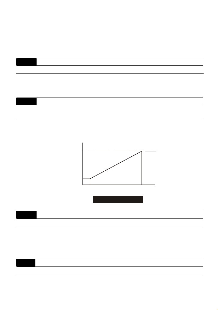
Chapter 5 Parameters|VFD-S Series
This parameter sets the Mid-Point Voltage of any V/f curve. With this setting, the V/f ratio
between Minimum Frequency and Mid-Point Frequency can be determined. This parameter
must be equal to or greater than Minimum Output Voltage (Pr.1-06) and equal to or less than
Maximum Output Voltage (Pr.1-02).
1-05 Minimum Output Frequency (Fmin) Unit: 0.1
Settings d1.0 to d60.0Hz Factory Setting: d1.0
This parameter sets the Minimum Output Frequency of the AC drive. This parameter must be
equal to or less than Mid-Point Frequency (Pr.1-03).
1-06 Minimum Output Voltage (Vmin) Unit: 0.1
Settings 115V/230V series d2.0 to d255V Factory Setting: d12.0
460V series d4.0 to d510V Factory Setting: d24.0
This parameter sets Minimum Output Voltage of the AC drive. This parameter must be equal
to or less than Mid-Point Voltage (Pr.1-04).
Voltag e
Pr.1-02
Pr.1-04
Pr.1-06
0
Pr.1-03
Pr.1-05
Standard V/F Curve
Pr.1-00
Pr.1-01
Freq.
1-07 Output Frequency Upper Limit Unit: 1
Settings d1 to d110% Factory Setting: d100
This parameter must be equal to or greater than the Output Frequency Lower Limit (Pr.1-08).
The Maximum Output Frequency (Pr.1-00) is regarded as 100%.
Output Frequency Upper Limit value = (Pr.1-00 * Pr.1-07)/100.
1-08
Output Frequency Lower Limit
Unit: 1
Settings d0 to d100% Factory Setting: d0
The Upper/Lower Limit is to prevent operation error and machine damage.
Revision August 2008, SE09, SW V2.61 5-23
Page 81

Chapter 5 Parameters|VFD-S Series
If the Upper Limit of Output Frequency is 50Hz and the Maximum Output Frequency is 60Hz,
the Maximum Output Frequency will be limited to 50Hz.
If the Lower Limit of Output Frequency is 10Hz, and the Minimum Output Frequency (Pr.1-05)
is set at 1.0Hz, then any Command Frequency between 1-10Hz will generate a 10Hz output
from the drive.
This parameter must be equal to or less than the Upper Limit of Output Frequency (Pr.1-07).
1-09 Acceleration Time 1 (Taccel 1) Unit: 0.1
1-10 Deceleration Time 1 (Tdecel 1) Unit: 0.1
1-11 Acceleration Time 2 (Taccel 2) Unit: 0.1
1-12 Deceleration Time 2 (Tdecel 2) Unit: 0.1
Settings d0.1 to d600Sec Factory Setting: d10.0
Pr.1-9- This parameter is used to determine the time required for the AC drive to ramp from 0
Hz to its Maximum Output Frequency (Pr.1-00). The rate is linear unless S-Curve is
“Enabled.”
Pr.1-10. This parameter is used to determine the time required for the AC drive to decelerate
from the Maximum Output Frequency (Pr.1-00) down to 0 Hz. The rate is linear unless S-
Curve is “Enabled.”
The acceleration/deceleration time 2 determines the time for the AC drive to
acceleration/deceleration from 0Hz to Maximum Output Frequency (Pr.1-00)
(acceleration/deceleration time 1 is the default). A Multi-Function Input terminal must be
programmed to select acceleration/deceleration time 2 and the terminals must be closed to
select acceleration/deceleration time 2. See Pr.4-04 to Pr.4-8-
In the diagram shown below, the acceleration/deceleration time of the AC drive is the time
between 0 Hz to Maximum Output Frequency (Pr.1-00). Suppose the Maximum Output
Frequency is 60 Hz, start-up frequency (Pr.1-05) is 1.0 Hz, and acceleration/deceleration time
is 10 seconds. The actual time for the AC drive to accelerate from start-up to 60 Hz is 9.83
seconds and the deceleration time is also 9.83 seconds.
1-13 Jog Acceleration/Deceleration Time Unit: 0.1Sec
Settings d0.1 to d600Sec Factory Setting: d10.0
1-14 Jog Frequency Unit: 0.1Hz
Settings d1.0 to d400Hz Factory Setting: d6.0
5-24 Revision August 2008, SE09, SW V2.61
Page 82
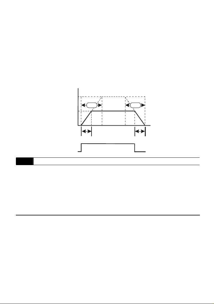
Chapter 5 Parameters|VFD-S Series
The JOG function can be selected using Multi-function Input terminals (Pr.4-04 to Pr.4-08) if
programmed for Jog (d10). When the Jog terminal is “closed”, the AC drive will accelerate
from Minimum Output Frequency (Pr.1-05) to Jog Frequency (Pr.1-14). When the Jog
terminal “open”, the AC drive will decelerate from Jog Frequency to zero. The
acceleration/deceleration time is decided by the Jog acceleration/deceleration time (Pr.1-13).
During operation, the AC drive cannot perform Jog command. And during Jog operation,
other operation commands cannot be accepted, except command of FORWARD, REVERSE
and STOP keys on the digital keypad.
Freque ncy
Max.
output
Freq.
Pr.1-00
Jog
Freq.
Pr.1-14
1-13 1-13
Time
Acceleration Time
Jog operation
command
ON
Deceleration Time
OFF
1-15 Auto-Acceleration / Deceleration
Factory Setting: d0
Settings d0 Linear Accel/Decel
d1 Auto Accel, Linear Decel
d2 Linear Accel, Auto Decel
d3 Auto Accel/Decel (Set by load)
d4 Linear Accel; Auto Decel, Stall Prevention during Decel
d5 Auto Accel/Decel, Stall Prevention during Decel
If the auto acceleration/deceleration is selected, the AC drive will acceleration/deceleration in
the fastest and smoothest means possible by automatically adjusting the time of
acceleration/deceleration.
Revision August 2008, SE09, SW V2.61 5-25
Page 83
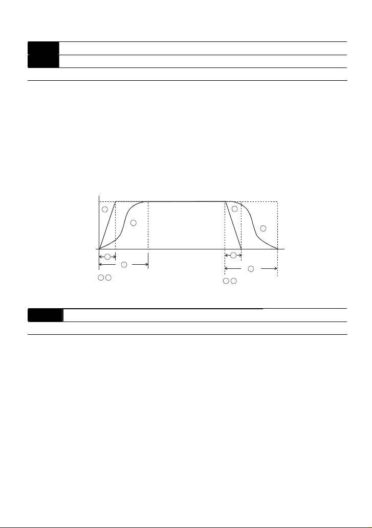
Chapter 5 Parameters|VFD-S Series
A
1-16 Acceleration S-Curve
1-17 Deceleration S-Curve
Settings d0 to d7 Factory Setting: d0
These two parameters allow you to configure whether the acceleration and/or deceleration
ramps are linear or S-shaped. The S-curve is enabled when set at d1-d7. Setting d1 offers
the quickest S-curve and d7 offers the longest and smoothest S-curve. The AC drive will not
follow the acceleration/deceleration time in Pr.1-09 to Pr.1-12. To Disable the S-curve, set
Pr.1-16 and Pr.1-17 to d0.
From the diagram shown below, the original setting acceleration/deceleration time will be for
reference when the function of the S-curve is enabled. The actual acceleration/deceleration
time will be determined based on the S-curve selected (d1 to d7).
1
1
3
1 2
Disable S curve
3
cceleration/deceleration Characteristics
2
2
4
3 4
Enable S curve
4
1-18 Jog Decelerating Time Unit: 0.1Sec
Settings d0.0 to d600 Factory Setting: d0.0
When Pr.1-18 is set to d0.0 Jog decelerating time determined by the setting of Pr.1-13 0.1 to
600 sec, Jog decelerating time can be set independently, separates from Pr.1-13.
When Pr.1-18 is set to 0.0, Pr.1-13 determines both Jog acceleration and deceleration time.
When Pr.1-18 is set between 0.1 to 600 seconds, which will determine Jog Decelerating Time
and Pr.1-13 will only determine Jog Accelerating Time.
5-26 Revision August 2008, SE09, SW V2.61
Page 84

Chapter 5 Parameters|VFD-S Series
V
Group 2: Operation Method Parameters
2-00 Source of Master Frequency Command
Factory Setting: d0
Settings d0 Master Frequency input determined by digital keypad. (record the
frequency of power loss and it can do analog overlap plus)
d1 Master Frequency determined by analog signal DC 0V-10V
(external terminal AVI). (won’t record the frequency of power loss
and it can’t do analog overlap plus)
d2 Master Frequency determined by analog signal DC 4mA-20mA
(external terminal AVI). (won’t record the frequency of power loss
and it can’t do analog overlap plus)
d3 Master Frequency determined by Potentiometer on the digital
keypad. (won’t record the frequency of power loss and it can do
analog overlap plus)
d4 Master Frequency operated by RS-485 serial communication
interface and record frequency of power loss. (record the frequency
of power loss and it can do analog overlap plus)
d5 Master Frequency operated by RS-485 serial communication
interface and won’t record frequency before power loss. (won’t
record the frequency of power loss and it can do analog overlap
plus)
This parameter sets the Frequency Command Source of the AC drive.
If the Frequency Command Source is external (DC 0 to +10V or 4 to 20mA), please make
sure the (AVI) terminal jumper is in the proper position as shown below.
Position of jumper: Please open the top cover. It is at the lower-left corner of the panel. The
jumper J1 determines the type of external analog input, either DC voltage signal or current
signal.
J1
oltage signal input(0-10V)
Current signal input(4-20mA)
When setting analog overlap plus, it needs to set Pr. 2-06 to select AVI or ACI.
Revision August 2008, SE09, SW V2.61 5-27
Page 85

Chapter 5 Parameters|VFD-S Series
2-01 Source of Operation Command
Factory Setting: d0
Settings d0 Controlled by the keypad
d1 External terminals. Keypad STOP/RESET enabled.
d2 External terminals. Keypad STOP/RESET disabled.
d3 RS-485 serial communication (RJ-11). Keypad STOP/RESET
enabled.
d4 RS-485 serial communication (RJ-11). Keypad STOP/RESET
disabled.
When the AC drive is controlled by an external source, please refer to parameter group 4 for
detailed explanations on related parameter settings.
2-02 Stop Method
Factory Setting: d0
Settings d0 STOP: ramp to stop E.F.: coast to stop
d1 STOP: coast to stop E.F.: coast to stop
The parameter determines how the motor is stopped when the AC motor drive receives a
valid stop command or detects External Fault.
Ramp: the AC motor drive decelerates to Minimum Output Frequency (Pr.1-05) according to
the deceleration time set in Pr.1-10 or Pr.1-12 and then stops.
Coast: the AC motor drive stops the output instantly upon command, and the motor free
runs until it comes to a complete standstill.
The motor stop method is usually determined by the characteristics of the motor load and
how frequently it is stopped.
(1) It is recommended to use “ramp to stop” for safety of personnel or to prevent material
from being wasted in applications where the motor has to stop after the drive is
stopped. The deceleration time has to be set accordingly.
(2) If motor free running is allowed or the load inertia is large, it is recommended to select
“coast to stop”. For example: blowers, punching machines, centrifuges and pumps.
5-28 Revision August 2008, SE09, SW V2.61
Page 86
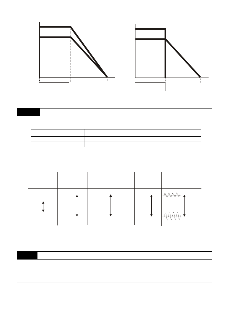
Frequency
output
frequency
motor
speed
Freque ncy
output
frequency
motor
speed
Chapter 5 Parameters|VFD-S Series
operation
command
RUN
stops according to
decel eration time
STOP
ra mp to sto p an d fre e ru n to st op
Time
operation
command
RUN
free run to stop
Time
STOP
2-03
PWM Carrier Frequency Selections
Unit: 1
115V/230V/460V Series
Power 0.25 to 3hp (0.2kW to 2.2kW)
Setting Range d3 to d10 kHz
Factory Setting d10 kHz
This parameter determines the PWM carrier frequency of the AC motor drive.
Carrier
Frequency
3kHz
10kHz
Acoustic
Noise
Significant
Minimal
Electromagnetic
Noise or leakage
current
Minimal
Significant
Heat
Dissipation
Minimal
Significant
Current
Wave
Minimal
Significant
From the table, we see that the PWM carrier frequency has a significant influence on the
electromagnetic noise, AC motor drive heat dissipation, and motor acoustic noise.
2-04 Motor Direction Control
Factory Setting: d0
Settings d0 Enable forward/reverse operation
d1 Disable reverse operation
The parameter determines whether the AC drive can operate in the reverse direction.
Revision August 2008, SE09, SW V2.61 5-29
Page 87

Chapter 5 Parameters|VFD-S Series
2-05 Loss of ACI Signal (4-20mA)
Factory Setting: d0
Settings d0 Decelerate to 0 Hz
d1 Coast to stop and display “EF”
d2 Continue operation by last frequency command
This parameter is only effective when the Source of Frequency is commanded by a 4 to
20mA signal. The ACI input is considered lost when the ACI signal falls below 2mA.
2-06 Analog Auxiliary Frequency Operation
Factory Setting: d0
Settings d0 Disable
d1 Enable + AVI (0~10V)
d2 Enable + ACI (4~20mA)
This parameter is used to determinate that the analog signal to overlap is 0~10V (AVI) or
4~20mA (ACI).
To make sure the short PIN of J1 on the panel is correct position before setting this parameter.
5-30 Revision August 2008, SE09, SW V2.61
Page 88
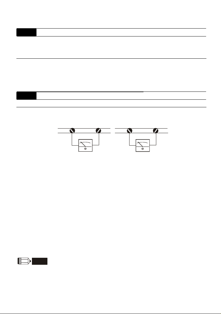
Chapter 5 Parameters|VFD-S Series
Group 3: Output Function Parameters
3-00
Analog Output Signal (AFM)
Factory Setting: d0
Settings d0 Analog Frequency Meter (0 to Maximum Output Frequency)
d1 Analog Current Meter (0 to 250% of rated AC motor drive current)
This parameter sets the function of the AFM output 0~+10VDC (ACM is common).
The voltage output type for this analog signal is PWM. It needs to read value by the movable
coil meter and is not suitable for A/D signal conversion.
3-01 Analog Output Gain Unit: 1
Settings d1 to d200% Factory Setting: d100
The parameter sets the voltage range of the analog output signal at terminals AFM, that
corresponds with either the output frequency or the output current of the VFD.
AFM
GND
AFM
GND
+-
Analog Frequency Meter
+-
Analog Current Meter
The analog output voltage is directly proportional to the output frequency of the AC drive. With
the factory setting of 100%, the Maximum Output Frequency (Pr.1-00) of the AC drive
corresponds to +10VDC analog voltage output. (The actual voltage is about +10VDC, and
can be adjusted by Pr.3-01).
The analog output voltage is directly proportional to the output current of the AC drive. With
the factory setting of 100%, the 2.5 times rated current of the AC drive corresponds to
+10VDC analog voltage output. (The actual voltage is about +10VDC, and can be adjusted by
Pr. 3-01)
The voltage output type of the output signal at terinals AFM is PWM, so this analog voltage is
only suitable to connect an external movable coil meter, not suitable to connect a digital meter
or for A/D signal conversion.
NOTE
Voltmeter specification: The sourcing capability of the output is limited to 0.21mA. Sourcing voltage:
10V. Output resistance: 47kΩ.
If the meter reads full scale at a voltage less than 10 volts, then Pr.3-01 should be set by the
following formula: Pr.3-01 = ((meter full scale voltage)/10) ×100%
Revision August 2008, SE09, SW V2.61 5-31
Page 89
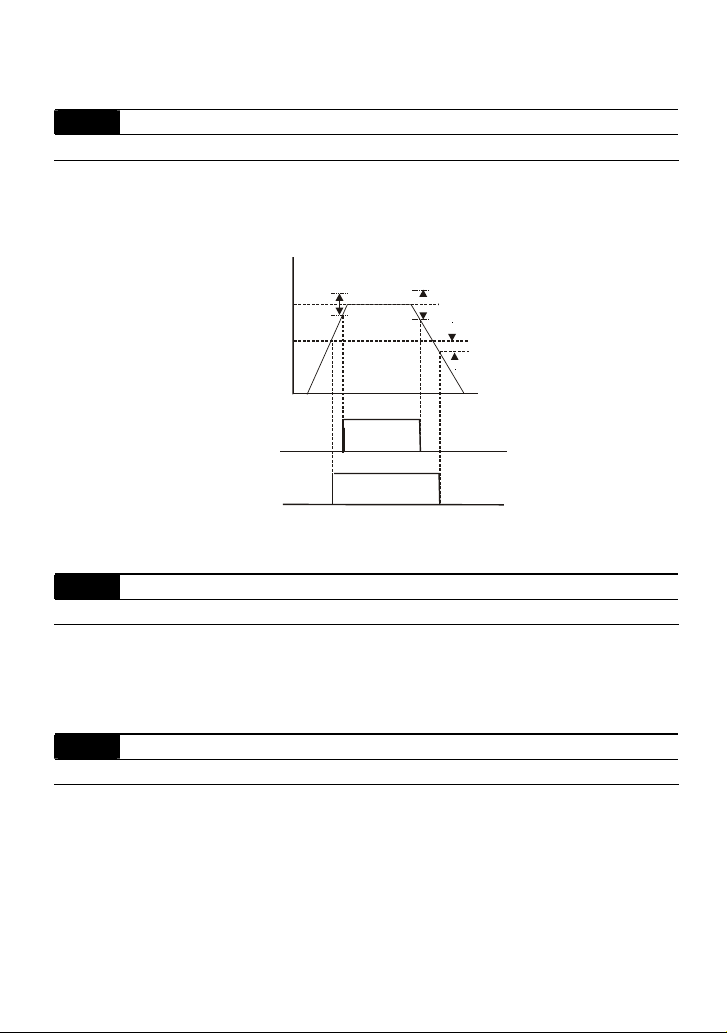
Chapter 5 Parameters|VFD-S Series
For example: When using the meter with full scale of 5 volts, adjust Pr.3-01 to 50%.
3-02 Desired Frequency Attained Unit: 0.1
Settings d1.0 to d400 Hz Factory Setting: d1.0
If a multi-function output terminal is set to function as Desired Frequency Attained (Pr.3-05 or
3-06=d9), then the output will be activated when the programmed frequency is attained.
Freq.
Max. Output
Freq.
Desired Freq.
Pr.3-02
Detecti on range
+
2Hz
-
Detecti on range
+
4Hz
-
Detection
range
-2Hz
Preset Freq.
Attained
indicati on
Pr.3-05 to 3-06
Desired Freq.
Attained
Indication
Pr.3-05 to 3-06
OFF
OFF
ON
ON
Desired Freq. Attained & Preset Freq. Attained
3-03 Terminal Count Value Unit: 1
Settings d0 to d999 Factory Setting: d0
The parameter determines the upper limit value of the internal counter. The internal counter
can be triggered by the external terminal (Pr.4-4 to Pr.4-8, d19). Upon completion of counting,
the specified output terminal will be activated. (Pr.3-05, Pr.3-06, d14).
3-04 Preliminary Count Value Unit: 1
Settings d0 to d999 Factory Setting: d0
When the counter value is counted up from “1” to the setting value of this parameter, the
corresponding multi-function output terminal which set to d15 as Preliminary Counter Value
Attained will be closed. The application can be that closing the multi-function output terminal
makes the AC drive operate at low speed until stop before the counting value is going to be
attained.
The timing diagram is shown below:
Time
OFF
OFF
5-32 Revision August 2008, SE09, SW V2.61
Page 90

Chapter 5 Parameters|VFD-S Series
Display
(Pr.0-04=d 1)
Counter Trig ger Signal
Multi-function Input Terminal
Preliminar y Counter Value Attained Output
(Pr. 3-04=d3)
(Pr. 3-05 to P r. 3-06=d15)
Terminal Count Value Attained Output
(Pr.3-03=d5)
(Pr.3-05 to Pr.3-06=d14)
TRG
The width of trigger signal
shou ld not be les s than
2ms(<25 0 Hz)
2ms
2ms
3-05
Multi-function Output Terminal 1 (Photocoupler output)
Factory Setting: d1
3-06
Multi-function Output Terminal 2 (relay output)
Factory Setting: d8
Settings d0 to d18
Setting Function Description
d0 No Function
d1 AC Drive Operational the output terminal will be activated when the drive is
running.
Master Frequency Attained the output will be activated when the AC drive attains
d2
Maximum Output Frequency.
d3 Zero Speed the output will be activated when Command Frequency
is lower than the Minimum Output Frequency.
d4 Over Torque Detection the output will be activated as long as the over-torque is
detected. Pr.6-04 determines the Over-Torque detection
level.
d5 Base-Block (B.B.) Indication the output will be activated when the output of the AC
drive is shut off by external Baseblock.
d6 Low-Voltage Indication the output will be activated when low voltage is detected.
d7 Operation Mode Indication the output will be activated when the operation of the AC
drive is controlled by External Control Terminals.
d8 Fault Indication the output will be activated when faults occur (oc, ov,
oH, oL, oL1, EF, cF3, HPF, ocA, ocd, ocn, GF).
d9 Desired Frequency Attained the output will be activated when the desired frequency
(Pr.3-02)is attained.
Revision August 2008, SE09, SW V2.61 5-33
Page 91

Chapter 5 Parameters|VFD-S Series
Setting Function Description
d10 PLC Program Running the output will be activated when the PLC program is
running.
d11 PLC Program Step
Completed
the output will be activated for 0.5 sec. when each multi-
step speed is attained.
d12 PLC Program Completed the output will be activated for 0.5 sec. when the PLC
program cycle has completed.
d13 PLC Operation Paused the output will be activated when PLC operation is
paused.
Terminal Count Value
d14
Attained
Preliminary Counter Value
d15
Attained
counter reaches Terminal Count Value.
counter reaches Preliminary Count Value.
d16 AC Motor Drive Ready
d17 FWD Command Indication When AC drive receives the command of forward
running, it will output immediately no matter AC drive is
in the state of run or stop.
d18 REV Command Indication When AC drive receives the command of reverse
running, it will output immediately no matter AC drive is
in the state of run or stop.
5-34 Revision August 2008, SE09, SW V2.61
Page 92

Chapter 5 Parameters|VFD-S Series
Group 4: Input Function Parameters
4-00 Potentiometer Bias Frequency Unit: 0. 1
Settings d0.0 to d100.0% Factory Setting: d0.0
4-01 Potentiometer Bias Polarity
Factory Setting: d0
Settings d0 Positive Bias
d1 Negative Bias
4-02 Potentiometer Frequency Gain Unit: 1
Settings d1 to d200% Factory Setting: d100
4-03 Potentiometer Reverse Motion Enable
Factory Setting: d0
Settings d0 Forward motion only
d1 Reverse motion enable (must be negative bias)
Pr.4-00 to Pr.4-03 are used when the source of frequency command is the analog signal (0 to
+10V DC or 4 to 20 mA DC). Refer to the following examples.
Example 1:
The following is the most common method. Set parameter 2-00 to d1 (0 to +10V signal) or d2 (4 to
20mA current signal).
Example 2:
In this example with the potentiometer set to 0V the Output Frequency is 10 Hz. The mid-point of
the potentiometer becomes 40 Hz. Once the Maximum Output Frequency is reached any further
increase of the potentiometer will not increase output frequency.
Revision August 2008, SE09, SW V2.61 5-35
Page 93

Chapter 5 Parameters|VFD-S Series
Example 3:
The example also shows the popular method. The whole scale of the potentiometer can be used as
desired. In addition to signals of 0 to 10V and4 to 20mA, the popular voltage signals also include
signals of 0 to 5V, 20 to 4mA or that under 10V. Regarding the setting, please refer to the following
examples.
Example 4:
This example shows a potentiometer range of 0 to 5 Volts.
Example 5:
In this example a 1 volt negative bias is used. In a noise environment, it is advantageous to use
negative bias to provide a noise margin (1V in this example).
5-36 Revision August 2008, SE09, SW V2.61
Page 94

Chapter 5 Parameters|VFD-S Series
z
Example 6:
In this example, a negative bias is used to provide a noise margin. Also a potentiometer frequency
gain is used to allow the Maximum Output Frequency to be reached.
Max.
Output
Freq.
Negative
bias 6H
Pr.1-00
60Hz
0Hz
0V
Gain adjustment
Factory Settings
Pr.1-00=60Hz--Max. output Freq.
Pr.4-00=10%--Potentiometer bias freq.
Pr.4-01=1 -- Bias polarity
Pr.4-02=111% -- Pot. freq. gain
Pr.4-03=0 -- Forward motion only
Calculation of gain
10V
1V
10V
Pr.4-02=(
)X100%=111%
9V
It's 0Hz
within
this
range.
Potentiometer Scale
27
0
54
Hz
10V
0V
Example 7:
In this example, the potentiometer is programmed to run a motor is both forward and reverse
direction. A motor will be idle when the potentiometer position is at mid-point of its scale. Using
Pr.4-03 will disable the external FWD and REV controls.
0V
Max.
Output
Freq.
REV
60Hz
30Hz
0Hz
Pr.1-00
FWD
5V
30Hz
60Hz
Factory Setti ngs
Pr.1-00=60H z--Max. output Freq.
Pr.4-00=30H z--Potentiom eter bias freq.
10V
Pr.4-01=1 -- bias polarity
Pr.4-02=200% -- pot. f req. gain
Pr.4-03=1 -- pot. REV motion enable
0
REV.
60
0V
FWD.
60
Hz
10V
Potentiometer Scale
Example 8:
In this example, the option of anti-slope is shown. Anti-slope is used in an application where control
of pressure, temperature, or flow is needed. Under a high pressure or flow situation, a sensor will
generate a large signal such as 20 mA or 10V. With anti-slope enable, the large signal will slow or
stop the AC drive.
Revision August 2008, SE09, SW V2.61 5-37
Page 95

Chapter 5 Parameters|VFD-S Series
Max.
Output
Freq.
60Hz
0Hz
Pr.1-00
0V
4mA
anti-s lope
Factory Settings
Pr.1-00=60Hz--Max. output Freq.
Pr.4-00=60 Hz--Potentiom eter bias freq.
Pr.4-01=1 -- bias polarity
Pr.4-02=100% -- pot. freq. gain
Pr.4-03=1 -- pot. REV. motion enable
10V
20mA
30
60
0V
4mA
Potentiometer Scale
0
10V
Hz
20mA
4-04 Multi-function Input Terminal (M0, M1)
Settings d0 to d29 (Only M1 can be set to d0~d29) Factory Setting: d1
4-05 Multi-function Input Terminal (M2)
Factory Setting: d6
4-06 Multi-function Input Terminal (M3)
Factory Setting: d7
4-07 Multi-function Input Terminal (M4)
Factory Setting: d8
4-08 Multi-function Input Terminal (M5)
Factory Setting: d9
Parameters & Functions table:
Value Function Value Function
d0 No Function d15 Up: Increment master frequency
d1 M0: FWD / STOP, M1: REV / STOP d16 Down: Decrement master frequency
d2 M0: RUN / STOP, M1: FWD / REV d17 Run PLC Program
3-Wire Operation Control mode (M0,
d3
M1, M2)
d4 External Fault (Normally Open) d19 Counter Trigger Signal
d5 External Fault (Normally Closed) d20 Counter Reset
d6 External Reset d21
d7 Multi-Step Speed Command1 d22 PID function disable
d8 Multi-Step Speed Command2 d23 JOG FWD
d9 Multi-Step Speed Command3 d24 JOG REV
d10 Jog operation d25
Acceleration/Deceleration Speed
d11
Inhibit
First or Second Acceleration or
d12
Deceleration Time Selection
External Base Block (N.O.)
d13
(Normally Open Contact Input)
External Base Block (N.C.)
d14
(Normally Close Contact Input)
d18 Pause PLC Program
Select ACI / Deselect AVI (the priority is
higher than Pr. 2-00 and d26)
The source of master frequency is AVI. (The
priority is higher than Pr. 2-00 and d26)
The source of master frequency is ACI. (The
d26
priority is higher than Pr. 2-00)
Press UP/DOWN
d27
forward/reverse (N.O.) motion
Press UP/DOWN
d28
forward/reverse (N.C.) motion
M0: 0: RUN 1: STOP, M1: no function,
d29
Direction is controlled by keypad
key to switch
key to switch
5-38 Revision August 2008, SE09, SW V2.61
Page 96
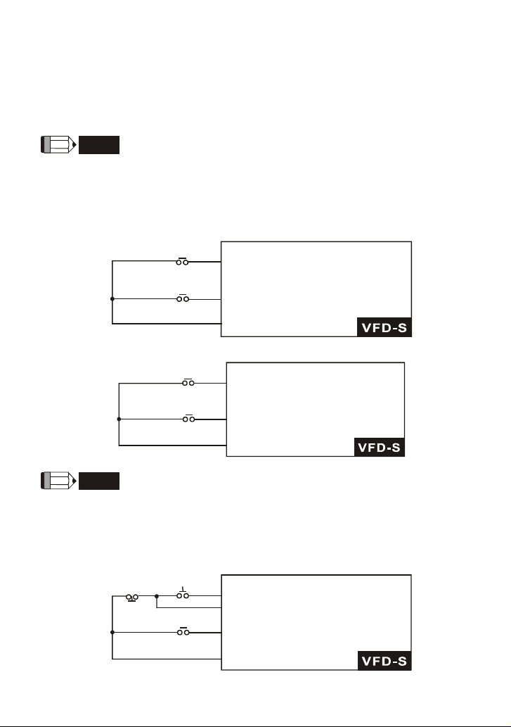
Chapter 5 Parameters|VFD-S Series
Explanations:
d0 Parameter Disable:
Enter value (d0) to disable any Multi-Function Input Terminal: M1 (Pr.4-04), M2 (Pr.4-05), M3 (Pr.4-
06), M4 (Pr.4-07) or M5 (Pr.4-08).
NOTE
The purpose of this function is to provide isolation for unused Multi-Function Input Terminals. Any
unused terminals should be programmed to d0 to insure they have no effect on drive operation.
d1 Two wire operation: Restricted to Pr.4-04 and external terminals M0, M1.
FWD/STOP
M0 "Open": Stop, "Cl ose ": FWD R un
REV/STOP
M1 "Open": Stop, "Close":REV Run
GND
d2 Two wire operation: Restrict to Pr. 4-04 and external terminals M0, M1.
M0 "Open": Stop, "Close": Run
RUN/STOP
REV/FWD
M1 "Open": FWD, "Close":REV
GND
NOTE
Multi-function Input Terminal M0 does not have its own parameter designation. M0 must be used in
conjunction with M1 to operate two and three wire control.
d3 Three Wire Control: Restricted to Pr.4-04 control terminals M0, M1, M2.
STOP RUN
M0 Run command, Runs when "close"
M2 Stop command, stops when "Open"
M1 REV/FWD Run selection
REV/FWD
"Open": FWD Run
"Close": REV Run
GND
Revision August 2008, SE09, SW V2.61 5-39
Page 97
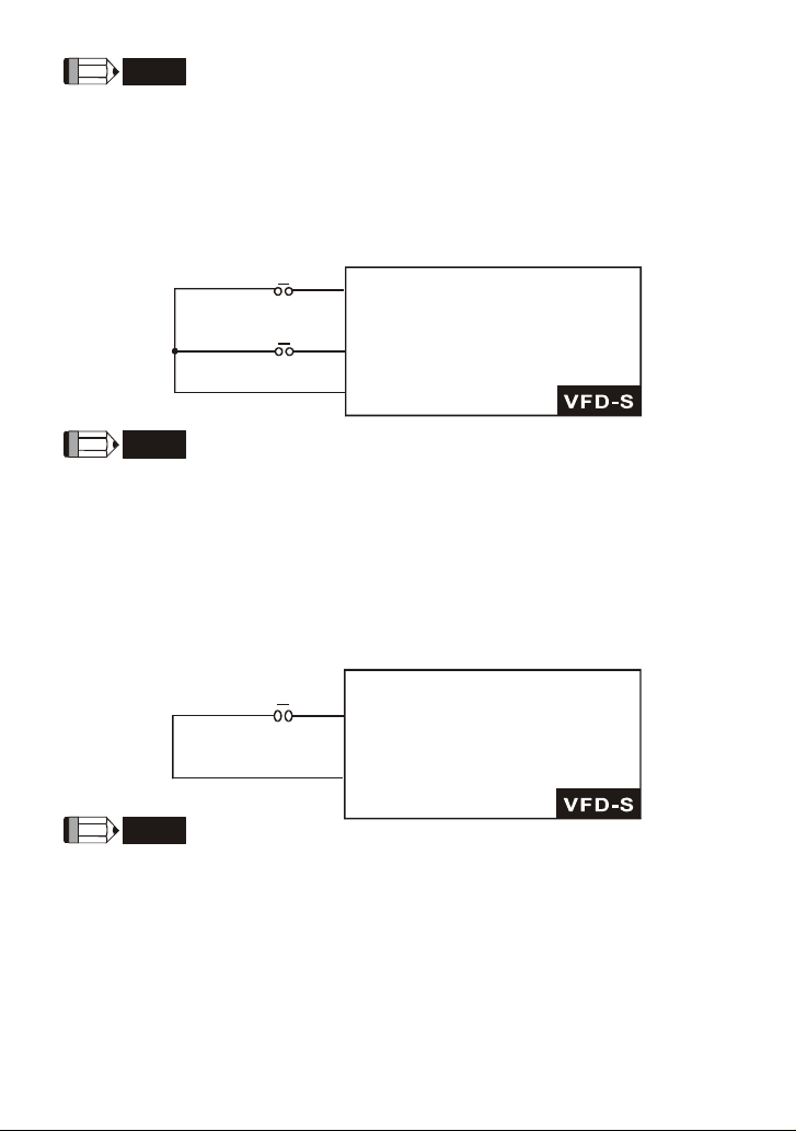
Chapter 5 Parameters|VFD-S Series
NOTE
When value d3 is selected for Pr. 4-04, this will over ride any value entered in Pr.4-05, since Pr.4-05
must be used for three wire control as shown above.
d4, d5 External Faults:
Parameter values d4, d5 programs Multi-Function Input Terminals: M1 (Pr. 4-04), M2 (Pr. 4-05), M3
(Pr. 4-06), M4 (Pr. 4-07) or M5 (Pr. 4-08) to be External Fault (E.F.) inputs.
NOTE
When an External Fault input signal is received, the AC drive will stop all output and display “ E.F.”
on Digital Keypad, the motor will free run. Normal operation can resume after the External Fault is
cleared and the AC drive is reset.
d6 External Reset:
Parameter value d6 programs a Multi-Function Input Terminal: M1 (Pr.4-04), M2 (Pr.4-05), M3 (Pr.4-
06), M4 (Pr.4-07) or M5 (Pr.4-08) to be an External Reset.
E.F.(N.O.)
setting by d4
E.F(N.C.)
setting by d5
RESET
setting by d6
Mx "Close": Operation available.
Mx "Open":Operation available.
GND
Mx "Close": Operation available
GND
NOTE
the External Reset has the same function as the Reset key on the Digital keypad. After external fault
such as O.H., O.C. and O.V. are clear, this input can be used to reset the drive.
d7, d8, d9 Multi-Step Speed Command:
Parameter values d7, d8, d9 programs any three of the following Multi-Function Input Terminals: M1
(Pr.4-04), M2 (Pr.4-05), M3 (Pr.4-06), M4 (Pr.4-07) or M5 (Pr.4-08) for multi-step speed command
function.
5-40 Revision August 2008, SE09, SW V2.61
Page 98
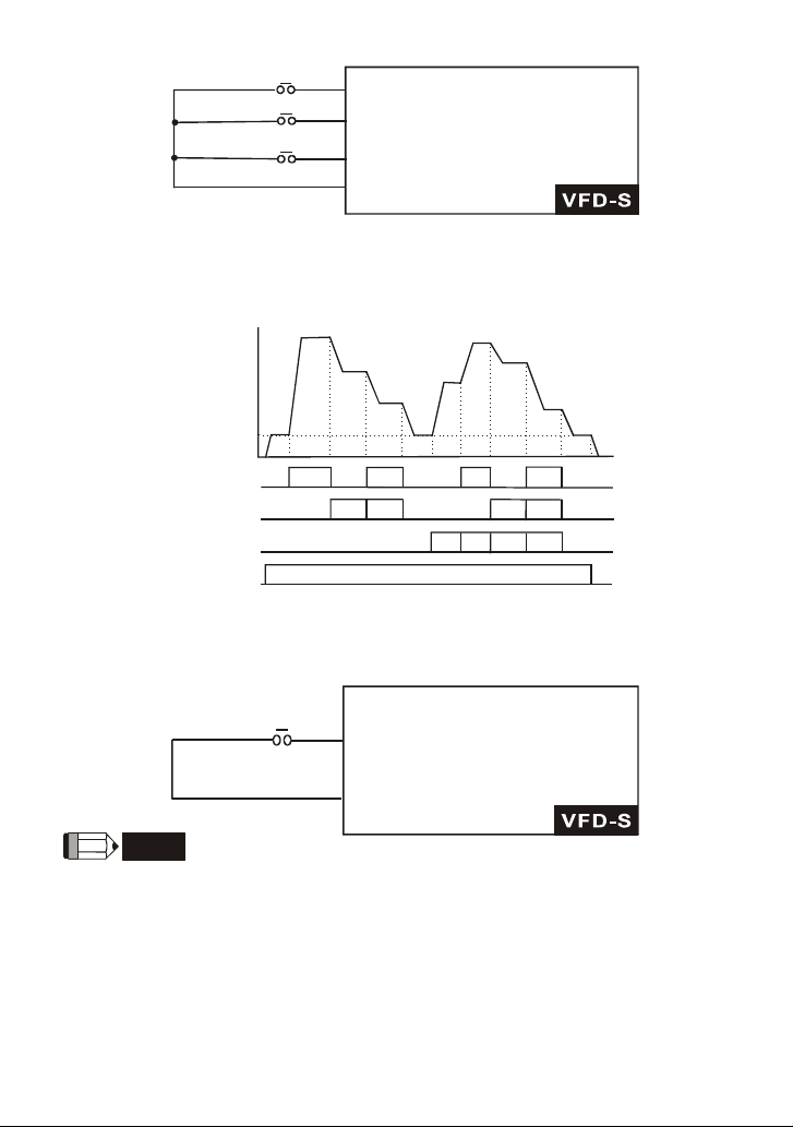
D7 Multi-step
1
Chapter 5 Parameters|VFD-S Series
Mx "Close": Operation available
D8 Multi -ste p 2
D9 Multi -ste p 3
Mx "Close": Operation available
Mx "Close": Operation available
GND
These three inputs select the multi-step speeds defined by Pr.5-00 to Pr.5-06 as shown in the
following diagram. Pr.5-07 to Pr.5-16 can also control output speed by programming the AC drive’s
internal PLC function.
Pr.5-00
Freq.
Step 1
Pr.5-01
Step 2
Pr.5-02
Step 3
Pr.5-03
Step 4
Pr.5-04
Step 5
Pr.5-05
Step 6
Pr.5-06
Step 7
Master Freq.
Mx1-GND
Mx2-GND
Mx3-GND
Operation
Command
ON
ON
ON ON
ON
ON ON
ON
ON ON ON
ON ON
Time
OFF
d10 Jog Operation Control:
Parameter value d10 programs Multi-Function Input Terminal: M1 (Pr.4-04), M2 (Pr.4-05), M3 (Pr.4-
06), M4 (Pr.4-07) or M5 (Pr.4-08) for Jog control.
Mx "Close": Operation available
d10 jog opera tion
command
GND
NOTE
Jog operation programmed by d10 can only be initiated while the motor is stopped. (Refer to Pr.1-13,
Pr.1-14.)
d11 Acceleration/Deceleration Speed Inhibit:
Parameter value d11 programs Multi-Function Input Terminal: M1 (Pr.4-04), M2 (Pr.4-05), M3 (Pr.4-
06), M4 (Pr.4-07) or M5 (Pr.4-08) for Acceleration/deceleration Inhibit. When the command is
received, acceleration and deceleration is stopped and the AC drive maintains a constant speed.
Revision August 2008, SE09, SW V2.61 5-41
Page 99
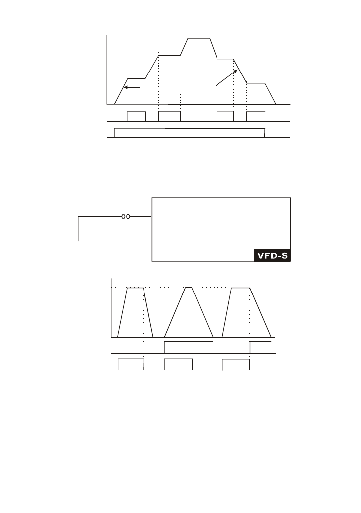
Chapter 5 Parameters|VFD-S Series
A
A
Frequenc y
Accelera tion
inhibit
Master Frequency
Acceleration
inhibit
Deceleration
inhibit
Deceleration
inhibit
Actual oper ation frequency
Time
Mx-GND
Operation
command
ON ON
ON
ON ON
OFF
d12 First or Second Acceleration/Deceleration Time Selection:
Parameter value d12 programs a Multi-Function Input Terminal: M1 (Pr.4-04), M2 (Pr.4-05), M3
(Pr.4-06), M4 (Pr.4-07) or M5 (Pr.4-08) to control selection of First or Second
Acceleration/deceleration time. (Refer to Pr.1-09 to Pr.1-12.)
Mx "Close": 2nd Acceleration /Decelerai on
Mx set d 12
"Open": 1st Acceleration/Deceleration
GND
Pr.
1-11
2nd
cceleration/
Deceleration
ON
ON
Pr.
1-12
Pr.
1-09
1st
Acceleration
ON
Pr.
1-12
2nd
Deceleration
ON
OFF
Time
Frequency
Master
Frequency
Mx-GND
operation
command
Pr.
1-09
1st
cceleration/
Deceleration
ON
Pr.
1-10
d13, d14 External Base Block:
Parameter values d13, d14 program Multi-Function Input Terminals: M1 (Pr.4-04), M2 (Pr.4-05), M3
(Pr.4-06), M4 (Pr.4-07) or M5 (Pr.4-08) for external Base Block control. Value d13 is for normally
open (N.O.) input, and value d14 is for a normally closed (N.C.) input.
5-42 Revision August 2008, SE09, SW V2.61
Page 100
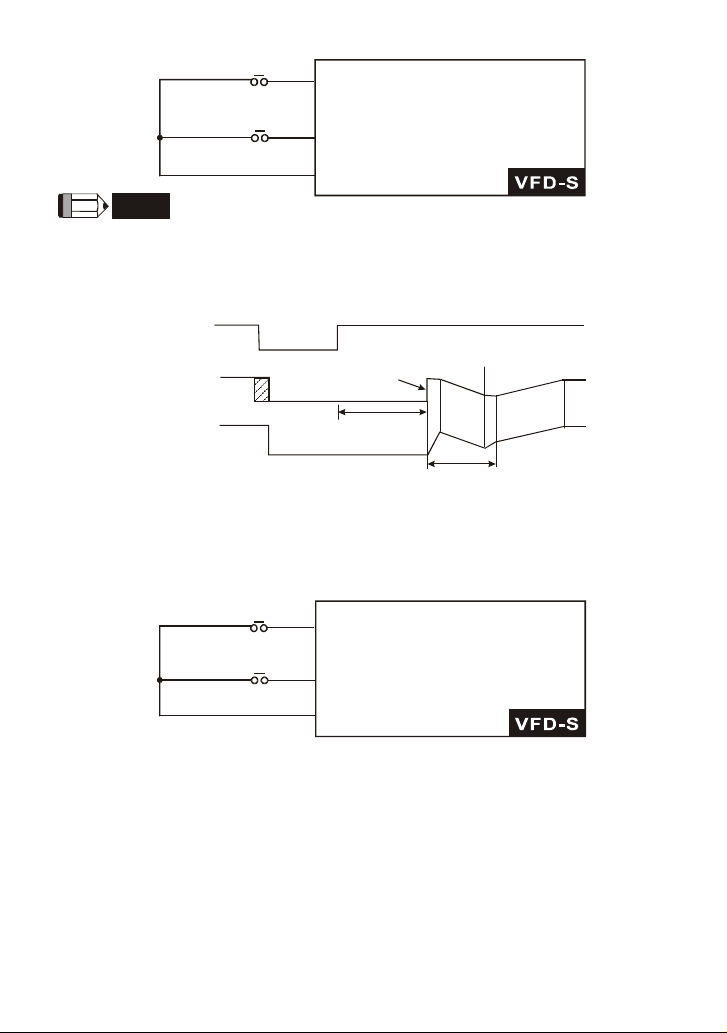
B.B.(N.O.)
Chapter 5 Parameters|VFD-S Series
setting by d13
Mx "Close": Operation available.
B.B.(N.C.)
Mx "Open":Operation available.
setting by d14
GND
NOTE
When a Base-Block signal is received, the AC drive will stop all output and the motor will free run.
When base block control is deactivated, the AC drive will start its speed search function and
synchronize with the motor speed, and then accelerate to Master Frequency.
External
base-block
signal
Output
frequency
Output
voltage
Pr.8-04=d1
Speed search starts with the
reference value
Min. base-block time
Pr.8-06
Speed synchronizati on
detection
Speed sear ch opera tion
d15, d16 Increase/Decrease Master Frequency:
Parameter values d15, d16 program the Multi-Function Input Terminals: M1 (Pr.4-04), M2 (Pr.4-05),
M3 (Pr.4-06), M4 (Pr.4-07) or M5 (Pr.4-08) to incrementally increase/ decrease the Master
Frequency each time an input is received.
UP
Mx " Cl ose": Freq. w il l increa se
setting by d15
DOWN
setting by d16
by one un it.
Mx "Close":Freq. will decrease
by one unit.
GND
d17, d18 PLC Function Control:
Parameter value d17 programs Multi-Function Input Terminal: M1 (Pr.4-04), M2 (Pr.4-05), M3 (Pr.4-
06), M4 (Pr.4-07) or M5 (Pr.4-08) to enable the AC drive internal PLC program. Parameter value
d18 programs an input terminal to pause the PLC program.
Revision August 2008, SE09, SW V2.61 5-43
 Loading...