

Page 1
Page 2
Page 3

Page 4

Preface
Thank you for choosing DELTA’s high-performance VFD-M Series. The VFD-M Series is
manufactured with high-quality components and materials and incorporate the latest microprocessor
technology available.
This manual is to be used for the installation, parameter setting, troubleshooting, and daily
maintenance of the AC motor drive. To guarantee safe operation of the equipment, read the following
safety guidelines before connecting power to the AC motor drive. Keep this operating manual at
hand and distribute to all users for reference.
To ensure the safety of operators and equipment, only qualified personnel familiar with AC motor
drive are to do installation, start-up and maintenance. Always read this manual thoroughly before
using VFD-M series AC Motor Drive, especially the WARNING, DANGER and CAUTION notes.
Failure to comply may result in personal injury and equipment damage. If you have any questions,
please contact your dealer.
PLEASE READ PRIOR TO INSTALLATION FOR SAFETY.
DANGER!
1. AC input power must be disconnected before any wiring to the AC motor drive is made.
2. A charge may still remain in the DC-link capacitors with hazardous voltages, even if the power
has been turned off. To prevent personal injury, please ensure that power has turned off before
opening the AC motor drive and wait ten minutes for the capacitors to discharge to safe voltage
levels.
3. Never reassemble internal components or wiring.
4. The AC motor drive may be destroyed beyond repair if incorrect cables are connected to the
input/output terminals. Never connect the AC motor drive output terminals U/T1, V/T2, and
W/T3 directly to the AC mains circuit power supply.
5. Ground the VFD-M using the ground terminal. The grounding method must comply with the
laws of the country where the AC motor drive is to be installed. Refer to the Basic Wiring
Diagram.
6. VFD-M series is used only to control variable speed of 3-phase induction motors, NOT for 1-
phase motors or other purpose.
7. VFD-M series shall NOT be used for life support equipment or any life safety situation.
Page 5

WARNI NG!
1. DO NOT use Hi-pot test for internal components. The semi-conductor used in AC motor drive
easily damage by high-voltage.
2. There are highly sensitive MOS components on the printed circuit boards. These components
are especially sensitive to static electricity. To prevent damage to these components, do not
touch these components or the circuit boards with metal objects or your bare hands.
3. Only qualified persons are allowed to install, wire and maintain AC motor drives.
CAUTION!
1. Some parameters settings can cause the motor to run immediately after applying power.
2. DO NOT install the AC motor drive in a place subjected to high temperature, direct sunlight,
high humidity, excessive vibration, corrosive gases or liquids, or airborne dust or metallic
particles.
3. Only use AC motor drives within specification. Failure to comply may result in fire, explosion or
electric shock.
4. To prevent personal injury, please keep children and unqualified people away from the
equipment.
5. When the motor cable between AC motor drive and motor is too long, the layer insulation of the
motor may be damaged. Please use a frequency inverter duty motor or add an AC output
reactor to prevent damage to the motor. Refer to appendix B Reactor for details.
6. The rated voltage for AC motor drive must be ≤ 240V for 230V models (≤ 120V for 115V models;
≤ 480V for 460V models; ≤ 600V for 575V models) and the mains supply current capacity must
be ≤ 5000A RMS.
Page 6

Table of Contents
Preface ............................................................................................................. i
Table of Contents .......................................................................................... iii
Chapter 1 Introduction................................................................................ 1-1
1.1 Receiving and Inspection.................................................................... 1-2
1.1.1 Nameplate Information................................................................ 1-2
1.1.2 Model Explanation ...................................................................... 1-2
1.1.3 Series Number Explanation ........................................................ 1-2
1.1.4 External Parts and Labels........................................................... 1-3
1.1.5 Remove Instructions ................................................................... 1-4
Remove Keypad.............................................................................. 1-4
Remove Front Cover....................................................................... 1-4
1.2 Preparation for Installation and Wiring................................................1-5
1.2.1 Ambient Conditions..................................................................... 1-5
1.2.2 Minimum Mounting Clearances................................................... 1-5
1.3 Dimensions.........................................................................................1-7
Chapter 2 Installation and Wiring .............................................................. 2-1
2.1 Basic Wiring Diagram .........................................................................2-2
2.2 External Wiring ...................................................................................2-5
2.3 Main Circuit......................................................................................... 2-6
2.3.1 Main Circuit Connection.............................................................. 2-6
Page 7

2.3.2 Main Circuit Terminals................................................................. 2-8
2.4 Control Terminal Wiring (Factory Settings) ........................................ 2-9
Chapter 3 Keypad and Start Up ..................................................................3-1
3.1 Keypad............................................................................................... 3-1
3.1.1 Description of the Digital Keypad ................................................3-1
3.1.2 How to Operate the Digital Keypad LC-M02E ............................. 3-2
3.1.3 LC-M02E ..................................................................................... 3-3
3.2 Operation Method .............................................................................. 3-5
3.3 Trial Run ............................................................................................ 3-5
Chapter 4 Parameters..................................................................................4-1
4.1 Summary of Parameter Settings ........................................................ 4-2
4.2 Parameter Settings for Applications ................................................. 4-14
4.3 Description of Parameter Settings.................................................... 4-20
Chapter 5 Troubleshooting.........................................................................5-1
5.1 Over Current (OC).............................................................................. 5-1
5.2 Ground Fault ...................................................................................... 5-2
5.3 Over Voltage (OV).............................................................................. 5-2
5.4 Low Voltage (Lv) ................................................................................ 5-3
5.5 Over Heat (OH1) ................................................................................ 5-4
5.6 Overload ............................................................................................ 5-4
5.7 Keypad Display is Abnormal .............................................................. 5-5
5.8 Phase Loss (PHL) .............................................................................. 5-5
5.9 Motor cannot Run............................................................................... 5-6
5.10 Motor Speed cannot be Changed .................................................... 5-7
5.11 Motor Stalls during Acceleration....................................................... 5-8
Page 8

5.12 The Motor does not Run as Expected ..............................................5-8
5.13 Electromagnetic/Induction Noise ......................................................5-9
5.14 Environmental Condition................................................................... 5-9
5.15 Affecting Other Machines ...............................................................5-10
Chapter 6 Fault Code Information and Maintenance................................ 6-1
6.1 Fault Code Information .......................................................................6-1
6.1.1 Common Problems and Solutions............................................... 6-1
6.1.2 Reset .......................................................................................... 6-5
6.2 Maintenance and Inspections .............................................................6-5
Appendix A Specifications........................................................................ A-1
Appendix B Accessories........................................................................... B-1
B.1 All Brake Resistors & Brake Units Used in AC Motor Drives............. B-1
B.1.1 Dimensions and Weights for Brake Resistors& Brake Units....... B-3
B.2 Non-fuse Circuit Breaker Chart ......................................................... B-5
B.3 Fuse Specification Chart ................................................................... B-6
B.4 AC Reactor........................................................................................ B-7
B.4.1 AC Input Reactor Recommended Value..................................... B-7
B.4.2 AC Output Reactor Recommended Value..................................B-7
B.4.3 Applications ................................................................................B-8
B.5 Zero Phase Reactor (RF220X00A) ................................................. B-10
B.6 Remote Controller RC-01................................................................ B-11
B.7 PU06 ............................................................................................... B-12
B.7.1 Description of the Digital Keypad VFD-PU06 ...........................B-12
B.7.2 Explanation of Display Message...............................................B-12
Page 9

B.7.3 Operation Flow Chart................................................................B-13
B.8 AMD - EMI Filter Cross Reference ..................................................B-14
B.8.1 Dimensions ...............................................................................B-17
B.9 Din Rail ............................................................................................ B-19
B.9.1 Din Rail-DR01 Adapter .............................................................B-19
B.9.2 Din Rail-DR02 Adapter .............................................................B-20
Appendix C How to Select the Right AC Motor Drive .............................C-1
C.1 Capacity Formulas............................................................................. C-2
C.2 General Precaution............................................................................C-4
C.3 How to Choose a Suitable Motor .......................................................C-5
Page 10

Chapter 1 Introduction
The AC motor drive should be kept in the shipping carton or crate before installation. In order to
retain the warranty coverage, the AC motor drive should be stored properly when it is not to be used
for an extended period of time. Storage conditions are:
CAUTION!
1. Store in a clean and dry location free from direct sunlight or corrosive fumes.
2. Store within an ambient temperature range of -20
3. Store within a relative humidity range of 0% to 90% and non-condensing environment.
4. Store within an air pressure range of 86 kPA to 106kPA.
5. DO NOT place on the ground directly. It should be stored properly. Moreover, if the surrounding
environment is humid, you should put exsiccator in the package.
6. DO NOT store in an area with rapid changes in temperature. It may cause condensation and
frost.
7. If the AC motor drive is stored for more than 3 months, the temperature should not be higher
than 30 °C. Storage longer than one year is not recommended, it could result in the degradation
of the electrolytic capacitors.
8. When the AC motor drive is not used for longer time after installation on building sites or places
with humidity and dust, it’s best to move the AC motor drive to an environment as stated above.
°
C to +60 °C.
Revision May 2008, ME14, SW V3.04 1-1
Page 11
Chapter 1 Introduction|
M
5
1.1 Receiving and Inspection
This VFD-M AC motor drive has gone through rigorous quality control tests at the factory before
shipment. After receiving the AC motor drive, please check for the following:
Check to make sure that the package includes an AC motor drive, the User Manual/Quick Start
and CD, and rubber bushings.
Inspect the unit to assure it was not damaged during shipment.
Make sure that the part number indicated on the nameplate corresponds with the part number
of your order.
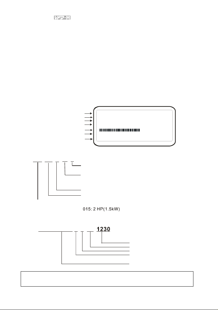
1.1.1 Nameplate Information
Example of 1HP 230V AC motor drive
AC Drive Model
Input Spec.
Output Frequency Range
Output Spec.
Bar Code
Serial Number
Software Version
MODE :V FD007M23A
INPUT :3PH 200 -240V 50/60Hz 6.0A
OUTPU T :3P H 0-240V 5.0A 1.9kVA 1HP
Freq. Range :0.1~400Hz
007M23A0T0011230
03.04
1.1.2 Model Explanation
23
VFD
007
Series Name
1.1.3 Series Number Explanation
D007M23A0
A
Ver si on Ty pe
Input Voltage
11:Single phase 115V
23:Three phase 230V
53:Three phase 575V
M Ser ies
Applicable motor capacity
004: 0.5 HP(0.4kW)
007: 1 HP(0.7kW)
022: 3 HP(2.2kW)
01
T
21:Single phase 230V
43:Three phase 460V
037: 5 HP(3.7kW)
055: 7.5HP(5.5kW)
075: 10HP(7.5kW)
Production number
Production week
Production year 2005
Production factory
230V 3-phase 1HP(0.75kW)
If the nameplate information does not correspond to your purchase order or if there are
any problems, please contact your distributor.
1-2 Revision May 2008, ME14, SW V3.04
(Taoyuan)
Model
Page 12
Chapter 1 Introduction|
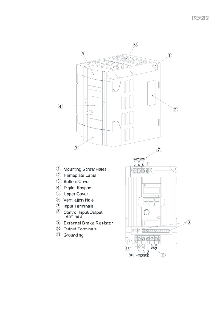
1.1.4 External Parts and Labels
Revision May 2008, ME14, SW V3.04 1-3
Page 13
Chapter 1 Introduction|
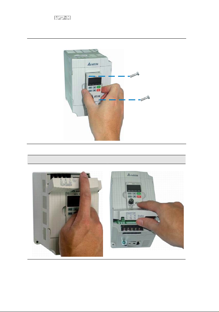
1.1.5 Remove Instructions
Remove Keypad
Remove Front Cover
RST Side UVW Side
1-4 Revision May 2008, ME14, SW V3.04
Page 14
Chapter 1 Introduction|
1.2 Preparation for Installation and Wiring
1.2.1 Ambient Conditions
Install the AC motor drive in an environment with the following conditions:
Air Temperature:
Relative Humidity: <90%, no condensation allowed
Operation
Storage
Transportation
Pollution
Degree
Atmosphere
pressure:
Installation Site
Altitude:
Vibration:
Temperature: -20°C ~ +60°C (-4°F ~ 140°F)
Relative Humidity: <90%, no condensation allowed
Atmosphere
pressure:
Vibration:
2: good for a factory type environment.
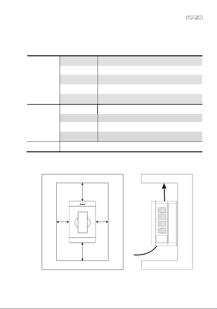
1.2.2 Minimum Mounting Clearances
-10 ~ +50°C (14 ~ 122°F) for UL & cUL
-10 ~ +40°C (14 ~ 104°F) for 5.5kw models and above
86 ~ 106 kPa
<1000m
<20Hz: 9.80 m/s2 (1G) max
20 ~ 50Hz: 5.88 m/s2 (0.6G) max
86 ~ 106 kPa
<20Hz: 9.80 m/s2 (1G) max
20 ~ 50Hz: 5.88 m/s2 (0.6G) max
150mm
50mm
50mm
150mm
Air Flow
Revision May 2008, ME14, SW V3.04 1-5
Page 15
Chapter 1 Introduction|
CAUTION!
1. Operating, storing or transporting the AC motor drive outside these conditions may cause
damage to the AC motor drive.
2. Failure to observe these precautions may void the warranty!
3. Mount the AC motor drive vertically on a flat vertical surface object by screws. Other directions
are not allowed.
4. The AC motor drive will generate heat during operation. Allow sufficient space around the unit
for heat dissipation.
5. The heat sink temperature may rise to 90°C when running. The material on which the AC motor
drive is mounted must be noncombustible and be able to withstand this high temperature.
6. When AC motor drive is installed in a confined space (e.g. cabinet), the surrounding
temperature must be within 10 ~ 40°C with good ventilation. DO NOT install the AC motor drive
in a space with bad ventilation.
7. Prevent fiber particles, scraps of paper, saw dust, metal particles, etc. from adhering to the
heatsink.
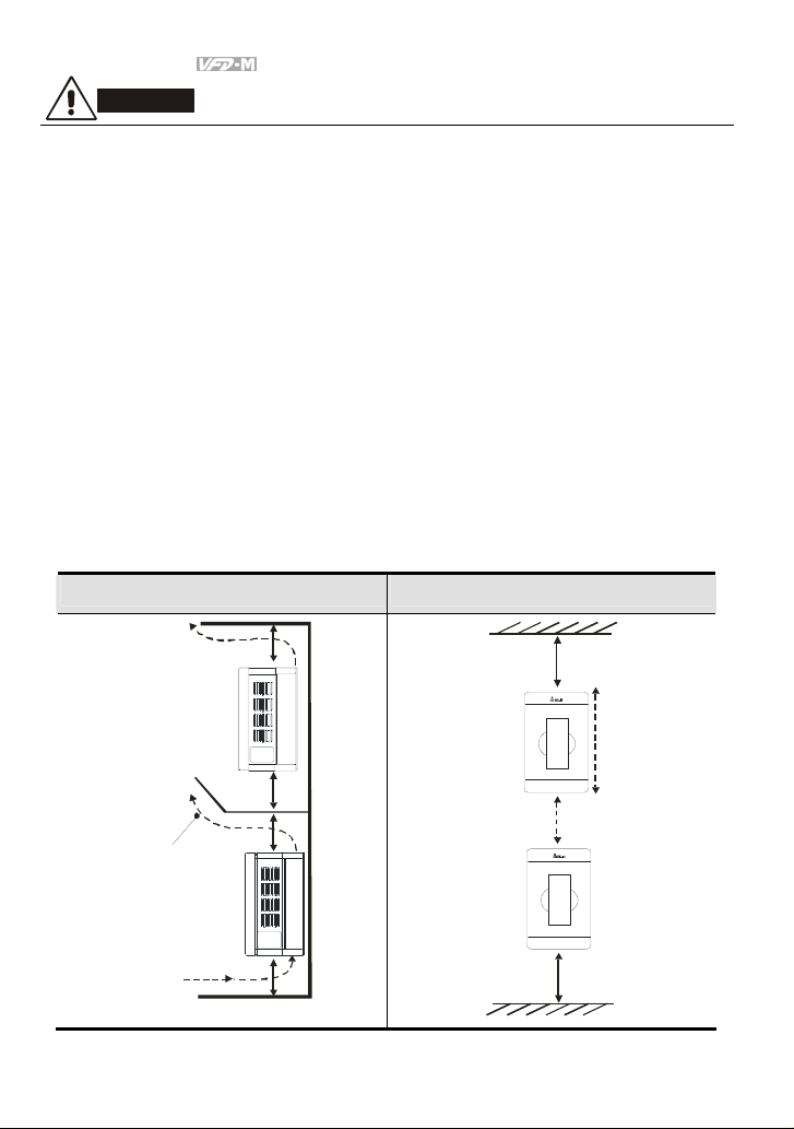
8. When installing multiple AC more drives in the same cabinet, they should be adjacent in a row
with enough space in-between. When installing one AC motor drive below another one, use a
metal separation between the AC motor drives to prevent mutual heating.
Installation with Metal Separation Installation without Metal Separation
150mm
150mm
B
150mm
B
Air Flow
150mm
150mm
Side View
150mm
1-6 Revision May 2008, ME14, SW V3.04
Page 16
Chapter 1 Introduction|
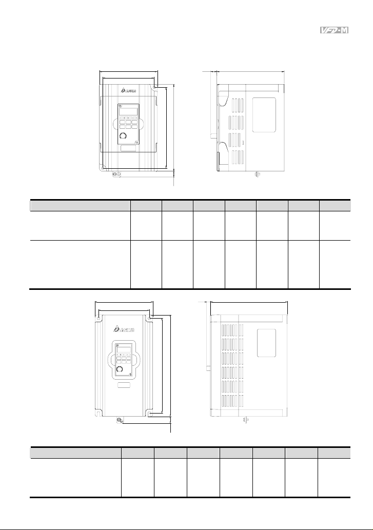
1.3 Dimensions
W
W1
H
H1
H2
DD1
Model Name W W1 H H1 H2 D D1
VFD004M21A/23A,
VFD007M21A/23A,
VFD015M21A/23A
85.0
[3.35]
74.0
[2.91]
141.5
[5.57]
130.5
[5.14]
10.0
[0.39]
VFD002M11A,
VFD004M11A/21B,
VFD007M11A/21B/43B/53A,
VFD015M21B/43B/53A,
VFD022M23B/43B/53A
100.0
[3.94]
W
W1
H1
89.0
[3.50]
151.0
[5.94]
D1 D
140.0
[5.51]
10.0
[0.39]
Unit: mm [inch]
113.0
[4.45]
116.5
[4.59]
10.0
[0.39]
10.5
[0.41]
H2 H
Unit: mm [inch]
Model Name W W1 H H1 H2 D D1
VFD022M21A,
VFD037M23A/43A/53A,
VFD055M23A/43A/53A,
125.0
[4.92]
110.0
[4.33]
220.0
[8.66]
205.0
[8.07]
15.0
[0.59]
166.3
[6.55]
8.2
[0.32]
VFD075M43A/53A
Revision May 2008, ME14, SW V3.04 1-7
Page 17

Chapter 1 Introduction|
This page intentionally left blank
1-8 Revision May 2008, ME14, SW V3.04
Page 18

Chapter 2 Installation and Wiring
After removing the front cover, check if the power and control terminals are clear. Be sure to observe
the following precautions when wiring.
General Wiring Information
Applicable Codes
All VFD-M series are Underwriters Laboratories, Inc. (UL) and Canadian Underwriters
Laboratories (cUL) listed, and therefore comply with the requirements of the National Electrical
Code (NEC) and the Canadian Electrical Code (CEC).
Installation intended to meet the UL and cUL requirements must follow the instructions provided
in “Wiring Notes” as a minimum standard. Follow all local codes that exceed UL and cUL
requirements. Refer to the technical data label affixed to the AC motor drive and the motor
nameplate for electrical data.
The "Line Fuse Specification" in Appendix B, lists the recommended fuse part number for each
VFD-M Series part number. These fuses (or equivalent) must be used on all installations where
compliance with U.L. standards is a required.
CAUTION!
1. Make sure that power is only applied to the R/L1, S/L2, T/L3 terminals. Failure to comply may
result in damage to the equipment. The voltage and current should lie within the range as
indicated on the nameplate.
2. All the units must be grounded directly to a common ground terminal to prevent lightning strike
or electric shock.
3. Please make sure to fasten the screw of the main circuit terminals to prevent sparks which is
made by the loose screws due to vibration.
4. Check following items after finishing the wiring:
A. Are all connections correct?
B. No loose wires?
C. No short-circuits between terminals or to ground?
Revision May 2008, ME14, SW V3.04 2-1
Page 19
Chapter 2 Installation and Wiring|
DANGER!
1. A charge may still remain in the DC bus capacitors with hazardous voltages even if the power
has been turned off. To prevent personal injury, please ensure that the power is turned off and
wait ten minutes for the capacitors to discharge to safe voltage levels before opening the AC
motor drive.
2. Only qualified personnel familiar with AC motor drives is allowed to perform installation, wiring
and commissioning.
3. Make sure that the power is off before doing any wiring to prevent electric shock.
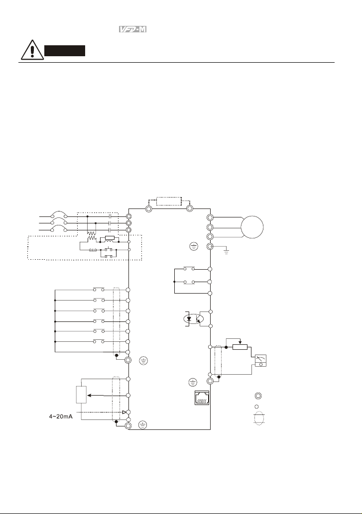
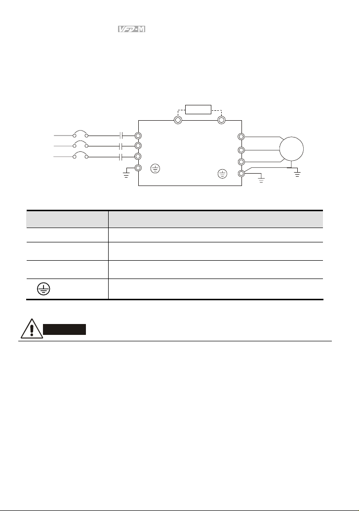
2.1 Basic Wiring Diagram
Users must connect wires according to the following circuit diagram shown below.
Brake Resistor (optional)
Mai n Circ uit P ower
NFB
R/L1
S/L2
T/L3
Recommended Circuit
when power supply
is turned OFF by a
fault output
Master Frequency setting
factory default is VR which is
on the digital keypad
Analog voltage
0~10VDC
:3K~
VR
Analog current
OFF
The spe c. of main ci rcui t
terminal is M3.0
Factory default
Forward/St op
Reverse/ Stop
Reset
Multi- step 1
Multi-st ep 2
Multi- step 3
Common signal
3
VR
5KΩ
1
NOTE: Do not plug a Modem or telephone line to the RS-485 communication
p ort, pe rmane nt dama ge may resu lt. Termin al 1& 2 are the pow er
s ources for the optional copy keypad and should not be used while
u sing RS -485 comm unic atio n.
* If it is single phase model, please select any of the two input power
terminals in main circuit power.
* Single phase model can be input 3-phase power.
B1
R/L1
S/L2
T/L3
SA
RB
MC
RC
ON
MC
M0
M1
M2
M3
M4
M5
GND
E
Power for speed setting
+10V 10mA(MAX)
2
AVI
ACI
GND
E
B2
RS-485
series interface
U/T1
V/T2
W/T3
MO1
MCM
AFM
GND
RJ-11
E
RA
RB
RC
E
6←1
AC Motor
IM
3~
Grounding
Multi-function indication
output contact
120VAC/250VAC 5A
24VDC less than 2.5A
Factory default:
indicates malfunctio n
Multi-function Photocoupler
output contact 48VDC 50mA
Factory default: Indicates
during operation
VR(1KΩ)
For adjustment
Analog output
Factory default:
output frequen cy
1:15V
2:GND
3:SG4:SG+
5:Reserved
6:Reserved
+
-
~
DC 0
Main circuit (power)
terminal s
Control circui t terminals
Shielded leads
10V
2-2 Revision May 2008, ME14, SW V3.04
Page 20
Chapter 2 Installation and Wiring|
CAUTION!
1. The wiring of main circuit and control circuit should be separated to prevent erroneous actions.
2. Please use shield wire for the control wiring and not to expose the peeled-off net in front of the
terminal.
3. Please use the shield wire or tube for the power wiring and ground the two ends of the shield
wire or tube.
4. Damaged insulation of wiring may cause personal injury or damage to circuits/equipment if it
comes in contact with high voltage.
5. The AC motor drive, motor and wiring may cause interference. To prevent the equipment
damage, please take care of the erroneous actions of the surrounding sensors and the
equipment.
6. When the AC drive output terminals U/T1, V/T2, and W/T3 are connected to the motor terminals
U/T1, V/T2, and W/T3, respectively. To permanently reverse the direction of motor rotation,
switch over any of the two motor leads.
7. With long motor cables, high capacitive switching current peaks can cause over-current, high
leakage current or lower current readout accuracy. To prevent this, the motor cable should be
less than 20m for 3.7kW models and below. And the cable should be less than 50m for 5.5kW
models and above. For longer motor cables use an AC output reactor.
8. The AC motor drive, electric welding machine and the greater horsepower motor should be
grounded separately.
9. Use ground leads that comply with local regulations and keep them as short as possible.
10. No brake resistor is built in the VFD-M series, it can install brake resistor for those occasions
that use higher load inertia or frequent start/stop. Refer to Appendix B for details.
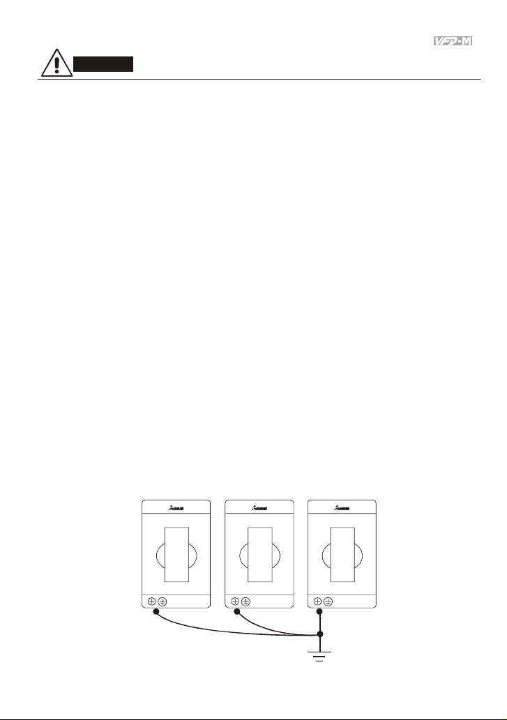
11. Multiple VFD-M units can be installed in one location. All the units should be grounded directly
to a common ground terminal, as shown in the figure below. Ensure there are no ground
loops.
Excellent
Revision May 2008, ME14, SW V3.04 2-3
Page 21
Chapter 2 Installation and Wiring|
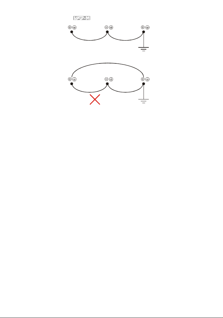
Good
Not allowed
2-4 Revision May 2008, ME14, SW V3.04
Page 22
Chapter 2 Installation and Wiring|
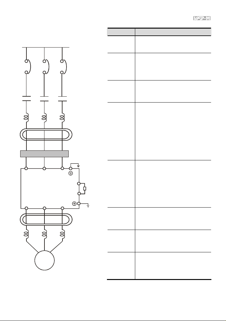
2.2 External Wiring
Power Supply
EMI Filter
R/L1 S/L2
U/T1 V/T2
Motor
T/L3
W/T3
FUSE/NFB
Magnetic
contactor
Input AC
Line Reactor
Zero-phase
Reactor
B1
B2
Zero-phase
Reactor
Output AC
Line Reactor
Brake
Resistor
Items Explanations
Power
supply
Please follow the specific power
supply requirement shown in
APPENDIX A.
There may be inrush current during
Fuse/NFB
(Optional)
power up. Please check the chart of
APPENDIX B and select the correct
fuse with rated current. NFB is
optional.
Magnetic
contactor
(Optional)
Please do not use a Magnetic
contactor as the I/O switch of the AC
drive, this will reduce the operating
life cycle of the AC drive.
Used to improve the input power
factor, to reduce harmonics and
provide protection from AC line
Input AC
Line Reactor
(Optional)
disturbances. (Surge, switching
spike, power flick, etc.) AC line
reactor should be installed when the
power supply capacity is ≧500kVA
or phase lead reactor will be
switched. And the wiring distance
should not exceed 10m. Please refer
to Appendix B for detail.
Zero phase reactors are used to
Zero-phase
Reactor
(Ferrite Core
Common
Choke)
(Optional)
reduce radio noise especially when
audio equipment installed near the
inverter. Effective for noise reduction
on both the input and output sides.
Attenuation quality is good for a wide
range from AM band to 10Mhz.
Appendix B specifies zero phase
reactors. (RF220X00A)
EMI filter
(Optional)
Brake
Resistor
(Optional)
Output AC
Line Reactor
(Optional)
To reduce electromagnetic
interference. Please refer to
Appendix B for detail.
Used to reduce stopping time of the
motor. Please refer to the chart on
Appendix B for specific brake
resistors.
Motor surge voltage amplitudes
depending on motor cable length. For
long motor cable applications (>20m),
it is necessary to install on the
inverter output side.
Revision May 2008, ME14, SW V3.04 2-5
Page 23
Chapter 2 Installation and Wiring|
2.3 Main Circuit
2.3.1 Main Circuit Connection
Non-fuse breaker
(NFB)
R
S
T
MC
R(L1)
S(L2)
T(L3)
E
Brake Res istor
(Optional )
BR
B1
B2
U(T1)
V(T2)
W(T3)
Terminal Symbol Explanation of Terminal Function
R/L1, S/L2, T/L3 AC line input terminals (three phase)
U/T1, V/T2, W/T3 Motor connections
B1 – B2 Connections for brake resistor (optional)
Motor
IM
3~
E
CAUTION!
Mains power terminals (R/L1, S/L2, T/L3)
Connect these terminals (R/L1, S/L2, T/L3) via a non-fuse breaker or earth leakage breaker to
3-phase AC power (some models to 1-phase AC power) for circuit protection. It is unnecessary
to consider phase-sequence.
It is recommended to add a magnetic contactor (MC) in the power input wiring to cut off power
quickly and reduce malfunction when activating the protection function of AC motor drives. Both
ends of the MC should have an R-C surge absorber.
Please make sure to fasten the screw of the main circuit terminals to prevent sparks which is
made by the loose screws due to vibration.
2-6 Revision May 2008, ME14, SW V3.04
Earth Ground
Page 24
Chapter 2 Installation and Wiring|
Please use voltage and current within the regulation shown in Appendix A.
When using a GFCI (Ground Fault Circuit Interrupter), select a current sensor with sensitivity of
200mA, and not less than 0.1-second detection time to avoid nuisance tripping.
Do NOT run/stop AC motor drives by turning the power ON/OFF. Run/stop AC motor drives by
RUN/STOP command via control terminals or keypad. If you still need to run/stop AC drives by
turning power ON/OFF, it is recommended to do so only ONCE per hour.
Do NOT connect 3-phase models to a 1-phase power source.
Output terminals for main circuit (U, V, W)
When it needs to install the filter at the output side of terminals U/T1, V/T2, W/T3 on the AC
motor drive. Please use inductance filter. Do not use phase-compensation capacitors or L-C
(Inductance-Capacitance) or R-C (Resistance-Capacitance), unless approved by Delta.
DO NOT connect phase-compensation capacitors or surge absorbers at the output terminals of
AC motor drives.
Use well-insulated motor, suitable for inverter operation.
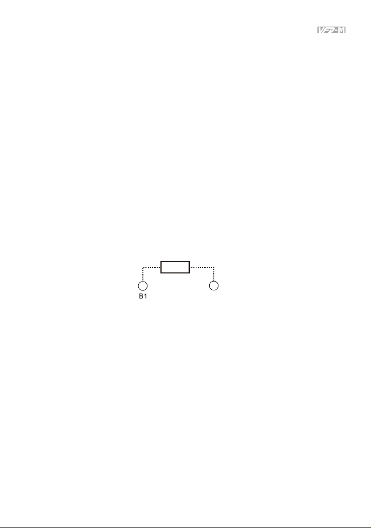
Terminals [B1, B2] for connecting external brake unit
Brake Resistor(optional)
Refer to Appendix B for the use of
special brake resistor
BR
Connect a brake resistor or brake unit in applications with frequent deceleration ramps, short
deceleration time, too low braking torque or requiring increased braking torque.
The AC motor drive has a built-in brake chopper, you can connect the external brake resistor to
the terminals [B1, B2] when needed.
When not used, please leave the terminals [B1, B2] open.
Revision May 2008, ME14, SW V3.04 2-7
B2
Page 25
Chapter 2 Installation and Wiring|
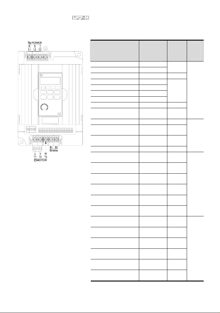
2.3.2 Main Circuit Terminals
Wire Type: 75 oC Copper Only
Max.
Model Name
VFD002M11A 6A/1.6A
VFD004M11A 9A/2.5A
VFD007M11A 16A/4.2A 12 (3.3)
VFD004M21A/21B 6.3A/2.5A
VFD004M23A 3.2A/2.5A
VFD007M21A/21B 11.5A/5.0A
VFD007M23A 6.3A/5.0A
VFD015M21A/21B 15.7A/7.0A 12 (3.3)
VFD015M23A 9.0A/7.0A
VFD022M21A 27A/10A 8 (8.4)
VFD022M23B 15A/10A
VFD037M23A 19.6A/17A
VFD055M23A 28A/25A 8 (8.4)
VFD007M43B 4.2A/3.0A
VFD007M53A 2.4A/1.7A
VFD015M43B 5.7A/4.0A
VFD015M53A 4.2A/3.0A
VFD022M43B 6.0A/5.0A
VFD022M53A 5.9A/4.2A
VFD037M43A 8.5A/8.2A
VFD037M53A 7.0A/6.6A
VFD055M43A 14A/13A
VFD055M53A 10.5A/9.9A
VFD075M43A 23A/18A
VFD075M53A 12.9A/12.2A
Current
(input /
output)
Wire
Gauge
AWG
(mm2)
12-14
(3.3-2.1)
12-14
(3.3-2.1)
12-14
(3.3-2.1)
8-12
(8.4-3.3)
8-10
(8.4-5.3)
12-14
(3.3-2.1)
12-14
(3.3-2.1)
12-14
(3.3-2.1)
12-14
(3.3-2.1)
12-14
(3.3-2.1)
12-14
(3.3-2.1)
8-14
(8.4-2.1)
8-14
(8.4-2.1)
8-12
(8.4-3.3)
8-12
(8.4-3.3)
8-10
(8.4-5.3)
8-12
(8.4-3.3)
Torque
kgf-cm
(in-lbf)
14
(12)
15
(13)
14
(12)
15
(13)
Note: It needs to use the Recognized Ring Terminal to conduct a proper wiring.
2-8 Revision May 2008, ME14, SW V3.04
Page 26
Chapter 2 Installation and Wiring|
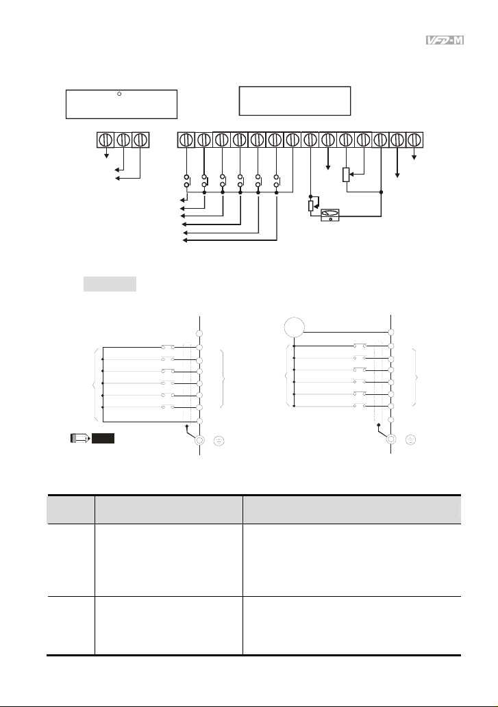
2.4 Control Terminal Wiring (Factory Settings)
Wire Type: 75 C, Copper Only
Wire Gauge : 2 4-12 AWG
Torque: 4kgf-cm (3.5 in-lbf)
RA RB RC
Relay contactor
Output
Factory Setting
Forward /Stop
Reverse/Stop
Reset
Multi-step speed 1
Multi- step speed 2
Multi- step speed 3
NPN Mode
NP N mode withou t extern al powe r
For ward/ St op
Reverse/Stop
ng
i
t
Reset
t
e
Multi-step 1
S
y
r
Multi-step 2
o
t
c
Multi-step 3
Fa
Com mon S ignal
NOTE
Don't apply the mains voltage
directly to above terminals .
Terminal symbols and functions
Terminal
Symbol
RA
RB
Terminal Function Factory Settings (NPN mode)
Multi-Function Relay Output
(N.O.) a
Multi-Function Relay Output
(N.C.) b
Wire Type: Copper Onl y
Wire Gauge: 22-16 AWG
Torque: 2kgf-cm (1.73 in-lbf)
M0 M1 M2M3M4M5GND AFM
NPN mode with external power
24
+
+24V
M0
M1
M2
M3
M4
M5
GND
E
s
l
n
a
o
n
i
i
t
c
m
r
n
e
u
f
T
-
t
i
t
l
u
p
u
n
M
I
Vdc
-
For ward/ St op
Reverse/Stop
ng
i
t
t
e
Reset
S
y
Multi-step 1
r
o
t
Multi-step 2
c
Multi-step 3
Fa
RA-RC
Resistive Load
5A(N.O.)/3A(N.C.) 277Vac;
5A(N.O.)/3A(N.C.) 30Vdc
Refer to P45 for programming.
RB-RC
Resistive Load
5A(N.O.)/3A(N.C.) 277Vac;
5A(N.O.)/3A(N.C.) 30Vdc
AVI
ACI
+10V
4~20mA
Bias
Potentiometer
Full scale voltmeter
0 to 10 VD C
MCM
GND
Photo coupler
output
Factory sett ing:
fault indication
+24V
M0
M1
M2
M3
M4
M5
GND
E
MO1
s
l
n
a
o
n
i
i
t
c
m
r
n
e
u
f
T
-
t
i
t
l
u
p
u
n
M
I
Revision May 2008, ME14, SW V3.04 2-9
Page 27
Chapter 2 Installation and Wiring|
Terminal
Symbol
Terminal Function Factory Settings (NPN mode)
RC Multi-function Relay Common
M0 Multi-function auxiliary input
M1 Multi-function input 1
M2 Multi-function input 2
M3 Multi-function input 3
M4 Multi-function input 4
M5 Multi-function input 5
GND Common Signal
+10V +10 Vdc Output
Analog Voltage Input
+10V
AVI Circuit
AVI
AVI
ACM
Internal Circuit
Analog Current Input
ACI Circuit
ACI
ACI
5A(N.O.)/3A(N.C.) 277Vac;
5A(N.O.)/3A(N.C.) 30Vdc
M0~M5-GND
Refer to P38~P42 for programming the multi-
function inputs.
ON: the activation current is 10 mA.
OFF: leakage current tolerance is 10μA.
+10V-GND
It can supply +10 VDC power.
Impedance: 20kΩ
Resolution: 10 bits
Range: 0~10Vdc = 0~Max.Output Frequency
Impedance: 250Ω
Resolution: 10 bits
Range: 4~20mA = 0~Max.Output Frequency
ACM
Internal Circuit
Analog Output Meter
ACM Circuit
AFM
0 to 10V, 2mA
Impedance: 100kΩ
AFM
Output Current: 2mA m ax
Resolution: 8 bits
Range: 0 ~ 10Vdc
0~10V
Potentiometer
Internal Circuit
2-10 Revision May 2008, ME14, SW V3.04
ACM
Max. 2mA
Page 28
Chapter 2 Installation and Wiring|
Terminal
Symbol
Terminal Function Factory Settings (NPN mode)
Maximum: 48Vdc, 50mA
Refer to P45 for programming.
Max: 48Vdc/50mA
MO1
Multi-function Output Terminal
MO1
(Photocoupler)
MO1-DCM
MCM
MCM
Multi-function Output Common
(Photocoupler)
Internal Circuit
Common for Multi-function Outputs
Note: Use twisted-shielded, twisted-pair or shielded-lead wires for the control signal wiring. It is
recommended to run all signal wiring in a separate steel conduit. The shield wire should only be
connected at the drive. Do not connect shield wire on both ends.
Analog inputs (AVI, ACI)
Analog input signals are easily affected by external noise. Use shielded wiring and keep it as
short as possible (<20m) with proper grounding. If the noise is inductive, connecting the shield
to terminal GND can bring improvement.
If the analog input signals are affected by noise from the AC motor drive, please connect a
capacitor (0.1μF and above) and ferrite core as indicated in the following diagrams:
C
ferrite core
AVI /AC I
GND
wind each wires 3 times or more around the core
Digital inputs (M0~M5)
When using contacts or switches to control the digital inputs, please use high quality
components to avoid contact bounce.
Digital outputs (MO1)
Make sure to connect the digital outputs to the right polarity, see wiring diagrams.
When connecting a relay to the digital outputs, connect a surge absorber or fly-back diode
across the coil and check the polarity.
Revision May 2008, ME14, SW V3.04 2-11
Page 29

Chapter 2 Installation and Wiring|
General
Keep control wiring as far away as possible from the power wiring and in separate conduits to
avoid interference. If necessary let them cross only at 90º angle.
The AC motor drive control wiring should be properly installed and not touch any live power
wiring or terminals.
NOTE
If a filter is required for reducing EMI (Electro Magnetic Interference), install it as close as
possible to AC drive. EMI can also be reduced by lowering the Carrier Frequency.
DANGER!
Damaged insulation of wiring may cause personal injury or damage to circuits/equipment if it comes
in contact with high voltage.
2-12 Revision May 2008, ME14, SW V3.04
Page 30
Chapter 3 Keypad and Start Up
3.1 Keypad
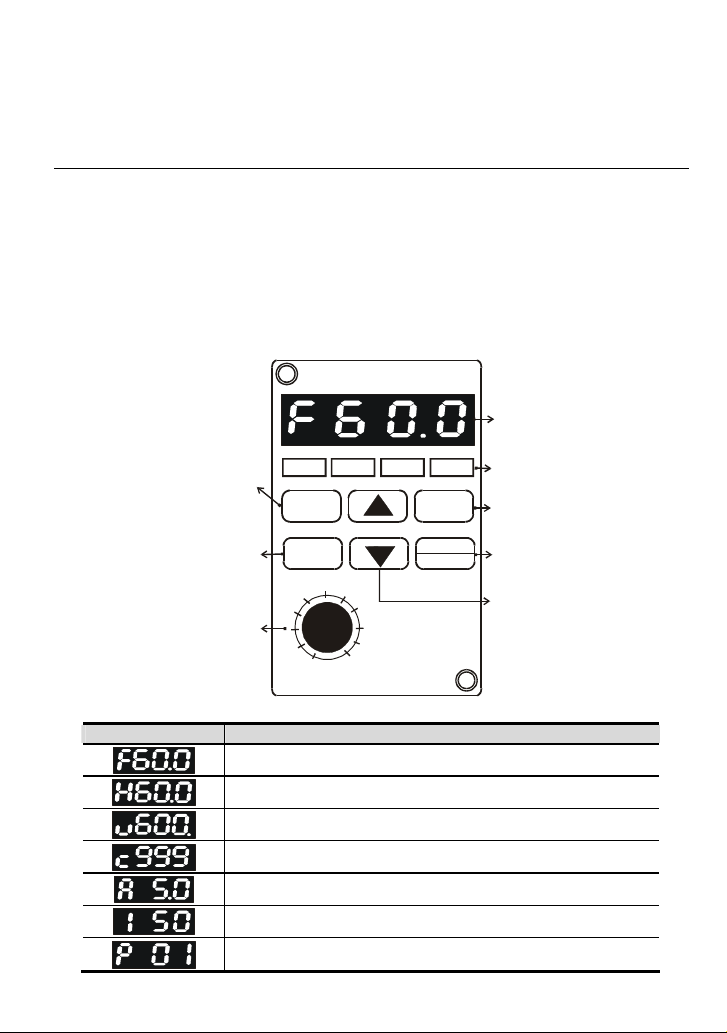
3.1.1 Description of the Digital Keypad
The digital keypad includes two parts: Display panel and keypad. The display panel provides the
parameter display and shows the operation status of the AC drive and the keypad provides
programming and control interface.
DIGITAL KEYPAD
LED Display
Indicates motor and
Program/Function mode key
Selects normal mode/
program mode. Displays
the AC drive status, such as
output freq., selects the
parameters.
Enter Key
Press ENTER after
key in the e lected
parameters or
change data.
Potentiometer
For master Frequency
setting refer to Pr.00.
RUN STOP FWD REV
MODE
ENTER
50
0
FREQ SET
LC-M02E
VFD-M
100
RUN
STOP
RESET
Displayed Message Descriptions
The AC drives Master Frequency.
The Actual Operation Frequency present at terminals U, V, and W.
The custom unit (v), where v = H x Pr.65.
The counter value (c).
The output current present at terminals U, V, and W
The internal PLC process step currently being performed.
The specified parameter.
Revision May 2008, ME14, SW V3.04 3-1
drive parameter.
LED Indicates
Lamp lights during RUN,
STOP, FWD & REV
operation.
Run key
Starts AC drive operation.
STOP/RESET Key
Stops and resets th e
parameter after a fault
occurs.
UP and DOWN Key
Sets the parameter number
or changes the numerical
data such as the freq.
reference.
Page 31

Chapter 3 Keypad and Start Up|
Displayed Message Descriptions
The actual value stored within the specified parameter.
The AC drive forward run status.
The AC drive reverse run status.
“End” displays for approximately 1 second if input has been
accepted. After a parameter value has been set, the new value is
automatically stored in memory. To modify an entry, use the
and
“Err” displays, if the input is invalid.
keys.
3.1.2 How to Operate the Digital Keypad LC-M02E
Se lectio n mod e
START
MODE
NOTE: In t he selecti on mode, pre ss to set th e paramet ers.
To s et p ar am ete rs
ENTER
NOTE : In the para meter sett ing mode, you c an press to retu rn to the sel ecti on mode.
To modify data
START
To set direction
(Whe n opera tion sour ce is digi tal k eypad)
or or
MODE MODE MODE MODE
ENTER
or
ENTER
MODE
MODE
ENTER
mov e to previ ous
disp lay
GO START
par ame ter set
successfully
or
par ame ter set
er ror
3-2 Revision May 2008, ME14, SW V3.04
Page 32

Chapter 3 Keypad and Start Up|
3.1.3 LC-M02E
Unit: mm [inch]
Reference Table for the 7-segment LED Display of the Digital Keypad
Digit 0 1 2 3 4 5 6 7 8 9
LED
Display
English
alphabet
LED
Display
English
alphabet
LED
Display
English
alphabet
LED
Display
A b Cc d E F G Hh I Jj
K L n Oo P q r S Tt U
v Y Z
Revision May 2008, ME14, SW V3.04 3-3
Page 33

Chapter 3 Keypad and Start Up|
Digital Keypad – Mounting Panel A
Unit: mm [inch]
Digital Keypad – Mounting Panel B
Unit: mm [inch]
3-4 Revision May 2008, ME14, SW V3.04
Page 34

Chapter 3 Keypad and Start Up|
3.2 Operation Method
The operation method can be set via control terminals and LC-M02E keypad. Please choose a
suitable method depending on application and operation rule.
Operation Method Frequency Source
Factory default
Operate from
external signal
Forward/Stop
Revers e/Stop
s
l
Reset
n
a
o
n
i
i
t
c
m
Multi-step 1
r
n
e
u
f
T
Multi-step 2
-
t
i
t
u
l
p
u
Multi-step 3
n
M
I
Common signal
Operation
Command Source
M0
M1
M2
M3
M4
M5
GND
E
M0-GND: FWD/Stop
M1~GND: REV/Stop
(Pr.01=01/02)
RUN
STOP
RESET
LC-M02E keypad
External terminals input (multi-step speed function)
M2~M5 (Pr.39~Pr.42)
(Pr.00=00)
3.3 Trial Run
The factory setting of the operation source is from the digital keypad (Pr.01=00). You can perform a
trial run by using the digital keypad with the following steps:
1. After applying power, verify that the display shows F60.0Hz. When AC motor drive is in
standby situation, STOP LED and FWD LED will light up.
2. Press
3. Press
key to set frequency to 5Hz.
RUN
key, RUN LED and FWD LED will light up, which indicates operation
command is forward running. And if you want to change to reverse running, you should
STOP
press
Revision May 2008, ME14, SW V3.04 3-5
. And if you want to decelerate to stop, please press
RESET
key.
Page 35

Chapter 3 Keypad and Start Up|
4. Check following items:
Check if the motor direction of rotation is correct.
Check if the motor runs steadily without abnormal noise and vibration.
Check if acceleration and deceleration are smooth.
If the results of trial run are normal, please start the formal run.
NOTE
1、 Stop running immediately if any fault occurs and refer to the troubleshooting guide for solving
the problem.
2、 Do NOT touch output terminals U, V, W when power is still applied to L1/R, L2/S, L3/T even
when the AC motor drive has stopped. The DC-link capacitors may still be charged to
hazardous voltage levels, even if the power has been turned off.
3、 To avoid damage to components, do not touch them or the circuit boards with metal objects or
your bare hands.
3-6 Revision May 2008, ME14, SW V3.04
Page 36

Chapter 4 Parameters
This VFD-M AC motor drive has 157 parameters for easy setting. In most applications, the user can
finish all parameter settings before start-up without the need for re-adjustment during operation.
Revision May 2008, ME14, SW V3.04 4-1
Page 37

Chapter 4 Parameters|
4.1 Summary of Parameter Settings
: The parameter can be set during operation.
Parameter Explanation Settings
Pr.00 Source of Frequency
Command
00: Master frequency determined by digital
keypad (LC-M02E)
01: Master frequency determined by 0 to
+10 V input on AVI terminal with jumpers
02: Master frequency determined by 4 to
20mA input on ACI terminal with jumpers
03: Master frequency determined by RS-485
Communication port
04: Master frequency determined by
potentiometer on digital keypad
Pr.01 Source of Operation
command
00: Operation determined by digital keypad
01: Operation determined by external control
terminals, keypad STOP is effective
02: Operation determined by external control
terminals, keypad STOP is ineffective
03: Operation determined by RS-485
communication port, keypad STOP is
effective
04: Operation determined by RS-485
communication port, keypad STOP is
ineffective
Pr.02 Stop Method 00: Ramp stop
01: Coast Stop
Pr.03 Maximum Output
50.00 to 400.0 Hz 60.00
Frequency
Pr.04 Maximum Voltage
10.00 to 400.0Hz 60.00
Frequency (Base
Frequency)
115V/230V: 0.1 to 255.0V 220.0
Maximum Output
Pr.05
Voltage (Vmax)
460V: 0.1 to 510.0V 440.0
575V: 0.1 to 637.0V 575.0
Pr.06 Mid-point Frequency 0.10 to 400.0Hz 1.50
115V/230V: 0.1 to 255.0V 10.0
Pr.07 Mid-point Voltage
460V: 0.1 to 510.0V 20.0
575V: 0.1 to 637.0V 26.1
Factory
Setting
00
00
00
Customer
4-2 Revision May 2008, ME14, SW V3.04
Page 38

Chapter 4 Parameters|
Parameter Explanation Settings
Factory
Setting
Customer
Pr.08 Minimum Output Freq 0.10 to 20.00Hz 1.50
Pr.09
Minimum Output
Voltage
115V/230V: 0.1 to 255.0V 10.0
460V: 0.1 to 510.0V 20.0
575V: 0.1 to 637.0V 26.1
Pr.10 Acceleration Time 1 0.1 to 600.0 sec or 0.01 to 600.0 sec 10.0
Pr.11 Deceleration Time 1 0.1 to 600.0 sec or 0.01 to 600.0 sec 10.0
Pr.12 Acceleration Time 2 0.1 to 600.0 sec or 0.01 to 600.0 sec 10.0
Pr.13 Deceleration Time 2 0.1 to 600.0 sec or 0.01 to 600.0 sec 10.0
Pr.14 Accel S-curve 00 to 07 00
Pr.15 Jog Accel/Decel Time 0.1 to 600.0 sec or 0.01 to 600.0 sec 1.0
Pr.16 Jog Frequency 0.00 to 400.0 Hz 6.00
Pr.17 1st Step Speed Freq. 0.00 to 400.0Hz 0.00
Pr.18 2nd Step Speed Freq. 0.00 to 400.0Hz 0.00
Pr.19 3rd Step Speed Freq. 0.00 to 400.0Hz 0.00
Pr.20 4th Step Speed Freq. 0.00 to 400.0Hz 0.00
Pr.21 5th Step Speed Freq. 0.00 to 400.0Hz 0.00
Pr.22 6th Step Speed Freq. 0.00 to 400.0Hz 0.00
Pr.23 7th Step Speed Freq. 0.00 to 400.0Hz 0.00
Pr.24
Pr.25
Reverse Operation
Inhibition
Over-Voltage Stall
Prevention
00: Enable REV operation
01: Disable REV operation
00
00: Disable
115V/230V: 330 to 450 Vdc 390
460V: 660 to 900 Vdc 780
575V: 825 to 1025 Vdc 975
Pr.26
Pr.27
Pr.28
Pr.29
Over-current Stall
Prevention during
Acceleration
Over-current Stall
Prevention during
Operation
DC Braking Current
Level
DC Braking during
Start-up
00: Disable
20% to 200%
00: Disable
20% to 200%
00 to 100 %
0.0 to 5.0 sec
150
150
00
0.0
Revision May 2008, ME14, SW V3.04 4-3
Page 39

Chapter 4 Parameters|
Parameter Explanation Settings
Pr.30
Pr.31
DC Braking during
Stopping
Start-point for DC
Braking
0.0 to 25.0 sec
0.00 to 60.00 Hz
00: Stop operation after momentary power
loss
01: Continues after momentary power loss,
speed search starts with Master
Frequency
02: Continues after momentary power loss,
Pr.32
Momentary Power
Loss Operation
Selection
speed search starts with Minimum output
Frequency
Pr.33
Pr.34
Pr.35
Maximum Allowable
Power Loss Time
Base-Block Time for
Speed Search
Maximum Current
Level for Speed
0.3 to 5.0 sec
0.3 to 5.0 sec
30 to 200 %
Search
Pr.36
Pr.37
Upper Bound of
Output Frequency
Lower Bound of
Output Frequency
0.10 Hz to 400.0 Hz
0.00 Hz to 400.0 Hz
00: M0: FWD/STOP, M1: REV/STOP
Pr.38
Multi-function Input
Terminal (M0,M1)
01: M0: RUN/STOP, M1: REV/FWD
02: M0, M1, M2: 3-wire operation control
mode
Pr.39
Pr.40
Pr.41
Multi-function Input
Terminal (M2)
Multi-function Input
Terminal (M3)
Multi-function Input
Terminal (M4)
00: No Function
01: Output OFF (N.O.) (enabled when
running)
02: Output OFF (N.C.) (enabled when
running)
03: External Fault (normally open) N.O.
04: External Fault (normally close) N.C
05: RESET
06: Multi-Step Speed Command 1
07: Multi-Step Speed Command 2
08: Multi-Step Speed Command 3
09: Jog Operation
10: Accel/Decel Speed Inhibit
Pr.42
Multi-function Input
Terminal (M5)
11: First or Second Accel/Decel Time
12: Base-block (B.B.) (N.O)
Factory
Setting
0.0
0.00
00
2.0
0.5
150
400.0
0.00
00
05
06
07
08
Customer
4-4 Revision May 2008, ME14, SW V3.04
Page 40

Chapter 4 Parameters|
Parameter Explanation Settings
13: Base-block (B.B.) (N.C)
Factory
Setting
Customer
14: Increase Master Frequency
15: Decrease Master Frequency
16: Run PLC Program
17: Pause PLC
18: Counter Trigger Signal
19: Counter Reset
20: No function
21: RESET command (N.C)
22: Control source: External Terminal
23: Control source: Keypad
24: Control source: Communication
25: Parameter Lock (Write disable, Read is
always 0)
26: PID Disable (N.O.)
27: PID Disable (N.C.)
28: Second Source for Frequency Command
29: Forward (contact is open) / Reverse
(contact is close)
30: One-Shot PLC Run
31: Index input signal
32: Counter Incremented by Drive Output
Frequency
00: Analog Frequency Meter (0 to Maximum
Output Frequency)
Pr.43 Analog Output Signal
01: Analog Current Meter (0 to 250% of the
rated AC drive current)
00
02: Feedback signal (0 - 100%)
03: Output power (0 - 100%)
Pr.44 Analog Output Gain 00 to 200 % 100
Pr.45
Multi-Function Output
Terminal 1
(Photocoupler output)
00: AC Drive Operational
01: Maximum Output Frequency Attained
02: Zero Speed
03: Over-Torque Detection
00
04: Base-Block (B.B) Indication
Pr.46
Multi-function Output
Terminal 2
(Relay Output)
05: Low Voltage Indication
06: AC Drive Operation Mode
07: Fault Indication
07
08: Desired Frequency Attained
Revision May 2008, ME14, SW V3.04 4-5
Page 41

Chapter 4 Parameters|
Parameter Explanation Settings
Factory
Setting
09: PLC Program Running
10: PLC Program Step Completed
11: PLC Program Completed
12: PLC Operation Paused
13: Top Count Value Attained
14: Preliminary Counter Value Attained
15: Warning (PID feedback loss,
communication error)
16: Below the Desired Frequency
17: PID supervision
18: Over Voltage supervision
19: Over Heat supervision
20: Over Current stall supervision
21: Over Voltage stall supervision
22: Forward command
23: Reverse command
24: Zero Speed (Includes Drive Stop)
Pr.47
Pr.48
Pr.49
Pr.50
Pr.51
Desired Frequency
Attained
Adjust Bias of External
Input Frequency
Potentiometer Bias
Polarity
Potentiometer
Frequency Gain
Potentiometer
Reverse Motion
Enable
0.00 to 400.0 Hz
0.00 to 200.0%
00: Positive Bias
01: Negative Bias
0.10 to 200.0%
00: Reverse Motion Disabled in negative
bias
01: Reverse Motion Enabled in negative bias
0.00
0.00
00
100.0
00
Pr.52 Motor Rated Current 30.0% FLA to 120.0% FLA FLA
Pr.53
Motor No-Load
Current
00%FLA to 99%FLA
0.4*FLA
Pr.54 Torque Compensation 00 to 10 00
Pr.55 Slip Compensation 0.00 to 10.00 0.00
Pr.56 Reserved
Pr.57 AC Drive Rated Current Display (unit: 0.1A) ##.#
00: Standard Motor (self cool motor)
Pr.58
Electronic Thermal
Overload Relay
01: Inverter Motor (auxiliary cool fan on
motor)
02
02: Inactive
Customer
4-6 Revision May 2008, ME14, SW V3.04
Page 42

Chapter 4 Parameters|
Parameter Explanation Settings
Pr.59
Electronic Thermal
Motor Overload
30 to 300 sec
00: Over-Torque Detection Disable
Factory
Setting
60
Customer
01: Enabled during constant speed operation
until the allowable time for detection
(Pr.62) elapses.
Pr.60
Over-Torque
Detection Mode
02: Enabled during constant speed operation
and halted after detection.
03: Enabled during acceleration until the
00
allowable time for detection (Pr.62)
elapses.
04: Enabled during acceleration and halted
after detection.
Pr.61
Pr.62
Pr.63
Over-Torque
Detection Level
Over-Torque
Detection Time
Loss of ACI
(4-20mA)
30 to 200 %
0.0 to 10.0 seconds
00: Decelerate to 0 Hz
01: Stop immediately and display "EF"
02: Continue operation by last frequency
150
0.1
00
command
00: Display AC drive output Frequency (Hz)
01: Display User-defined output Frequency
(H*Pr.65)
02: Output Voltage (E)
03: DC Bus Voltage (u)
04: PV (i)
05: Display the value of internal counter (c)
06: Display the setting frequency (F or o=%)
06
Pr.64
User Defined Function
for Display
07: Display the parameter setting (Pr.00)
08: Reserved
09: Output Current (A)
10: Display program operation (0.xxx), Fwd,
or Rev
Pr.65 Coefficient K 0.01 to 160.0 1.00
Pr.66
Communication
Frequency
0.00 to 400.0 Hz
0.00
Pr.67 Skip Frequency 1 0.00 to 400.0 Hz 0.00
Pr.68 Skip Frequency 2 0.00 to 400.0 Hz 0.00
Pr.69 Skip Frequency 3 0.00 to 400.0 Hz 0.00
Pr.70 Skip Frequency Band 0.00 to 20.00 Hz 0.00
Revision May 2008, ME14, SW V3.04 4-7
Page 43

Chapter 4 Parameters|
Parameter Explanation Settings
PWM Carrier
Pr.71
Frequency
Auto Restart Attempts
Pr.72
after Fault
115V/230V/460V series: 01 to 15
(The factory setting of VFD075M43A is 10)
575V series: 01 to 10 6
00 to 10
00: No fault occurred
01: Over-current (oc)
Pr.73 Present Fault Record 00
02: Over-voltage (ov)
03: Overheat (oH)
04: Overload (oL)
05: Overload 1 (oL1)
06: External Fault (EF)
07: CPU failure 1 (CF1)
08: CPU failure 3 (CF3)
Second Most Recent
Pr.74
Fault Record
09: Hardware Protection Failure (HPF)
10: Over-current during acceleration (oca)
11: Over-current during deceleration (ocd)
12: Over-current during steady state
operation (ocn)
13: Ground fault or fuse failure(GFF)
14: Low Voltage (not record)
15: 3 Phase Input Power Loss
16: EPROM failure (CF2)
Pr.75
Third Most Recent
Fault Record
17: External interrupt allowance(bb)
18: Overload (oL2)
19: Auto Adjustable accel/decel failure
(CFA)
20: CPU self detection failure (codE)
00: All parameters can be set/read
01: All parameters are read-only
Pr.76
Parameter Lock and
Configuration
02-08: Reserved
09: Resets all parameters to 50Hz factory
defaults
10: Resets all parameters to 60Hz factory
defaults
Pr.77
Time for Auto Reset
the Restart Times in
0.1 to 6000.0 sec
Abnormality
Factory
Setting
15
00
00
00
00
60.0
Customer
4-8 Revision May 2008, ME14, SW V3.04
Page 44

Chapter 4 Parameters|
Parameter Explanation Settings
00: Disable PLC operation
Factory
Setting
Customer
01: Execute one program cycle
Pr.78 PLC Operation Mode
02: Continuously execute program cycles
03: Execute one program cycle step by step
00
04: Continuously execute one program cycle
step by step
Pr.79
Pr.80
Pr.81
Pr.82
Pr.83
Pr.84
Pr.85
Pr.86
Pr.87
Pr.88
PLC FWD/REV
Motion
Identity Code of the
AC Motor Drive
Time Duration of 1st
Step Speed
Time Duration of 2nd
Step Speed
Time Duration of 3rd
Step Speed
Time Duration of 4th
Step Speed
Time Duration of 5th
Step Speed
Time Duration of 6th
Step Speed
Time Duration of 7th
Step Speed
Communication
Address
Pr.89 Transmission Speed
00 to 127
Read only
00 to 9999 sec
00 to 9999 sec
00 to 9999 sec
00 to 9999 sec
00 to 9999 sec
00 to 9999 sec
00 to 9999 sec
01 to 254
00: 4800 bps
01: 9600 bps
02: 19200 bps
00
##
00
00
00
00
00
00
00
01
01
03: 38400 bps
Pr.90
Transmission Fault
Treatment
00: Warn and Continue Operating
01: Warn and RAMP to Stop
02: Warn and COAST to Stop
03
03: Keep Operation without Warning
Pr.91 Time Out Detection
0.0: Disable
0.1 to 120.0 sec
00: MODBUS ASCII mode, <7,N,2>
0.0
01: MODBUS ASCII mode, <7,E,1>
Pr.92
Communication
Protocol
02: MODBUS ASCII mode, <7,O,1>
03: MODBUS RTU mode, <8,N,2>
00
04: MODBUS RTU mode, <8,E,1>
05: MODBUS RTU mode, <8,O,1>
Revision May 2008, ME14, SW V3.04 4-9
Page 45

Chapter 4 Parameters|
Parameter Explanation Settings
Accel 1 to Accel 2
Pr.93
Frequency Transition
Decel 1 to Decel 2
Pr.94
Frequency Transition
Pr.95 Auto Energy Saving
Counter Countdown
Pr.96
Complete
Preset counter
Pr.97
countdown
Total Time Count from
Pr.98
Power On (Days)
Total Time Count from
Pr.99
Power On (Minutes)
0.01 to 400.0
0.00: Disable
0.01 to 400.0
0.00: Disable
00: Disable auto energy saving
01: Enable auto energy saving
00 to 9999
00 to 9999
00 to 65535 days Read
00 to 1440 minutes Read
Factory
Setting
0.00
0.00
00
00
00
Only
Only
Customer
Pr.100 Software Version ##
00: Linear Accel/Decel
01: Auto Accel, Linear Decel
Pr.101
Auto Adjustable
Accel/Decel
02: Linear Accel, Auto Decel
03: Auto Accel/Decel
00
04: Linear Accel/Decel Stall Prevention
during Deceleration
00: AVR function enabled
Pr.102
Auto Voltage
Regulation (AVR)
01: AVR function disabled
02: AVR function disabled when stops
00
03: AVR function disabled when decel
Pr.103
Auto tune Motor
Parameters
Pr.104 R1 value
Pr.105 Control Mode
00: Disable
01: Auto tune for R1
02: Auto tune for R1 + No Load testing
00 to 65535 mΩ
00: V/F Control
01: Sensor-less Control
00
00
00
Pr.106 Rated Slip 0.00 to 10.00 Hz 3.00
Pr.107 Vector Voltage Filter 5 to 9999 (per 2ms) 10
Pr.108
Pr.109
Vector Slip
Compensation Filter
Selection for Zero
Speed Control
25 to 9999 (per 2ms)
00: No output
01: Control by DC voltage
50
00
4-10 Revision May 2008, ME14, SW V3.04
Page 46

Chapter 4 Parameters|
Parameter Explanation Settings
Pr.110
Voltage of Zero Speed
Control
0.0 to 20.0 % of Max. output voltage (Pr.05)
Factory
Setting
5.0
Customer
Pr.111 Decel S-curve 00 to 07 00
Pr.112
Pr.113
External Terminal
Scanning Time
Restart Method after
Fault (oc, ov, BB)
01 to 20
00: None speed search
01: Continue operation after fault speed
search from speed reference
02: Continue operation after fault speed
01
01
search from Minimum speed
00: Fan Off when the drive stop after 1 Min.
01: AC Drive Runs and Fan On, AC Drive
Pr.114 Cooling Fan Control
Stops and Fan Off
02
02: Always Run
03: Reserved
Pr.115
PID Set Point
Selection
00: Disable
01: Keypad (based on Pr.00 setting)
02: AVI (external 0-10V)
03: ACI (external 4-20mA)
00
04: PID set point (Pr.125)
00: Input positive PID feedback, PV from AVI
(0 to 10V)
01: Input negative PID feedback, PV from
Pr.116
PID Feedback
Terminal Selection
AVI (0 to 10V)
02: Input positive PID feedback, PV from
00
ACI (4 to 20mA)
03: Input negative PID feedback, PV from
ACI (4 to 20mA)
Pr.117 Proportional Gain (P) 0.0 to 10.0 1.0
Pr.118 Integral Time (I)
0.00: Disable
0.01 to 100.0 sec
1.00
Pr.119 Differential Time (D) 0.00 to 1.00 sec 0.00
Pr.120
Integration’s Upper
Bound Frequency
00 to 100 %
100 %
Pr.121 One-Time Delay 0.0 to 2.5 sec 0.0
Pr.122
Pr.123
Pr.124
PID Frequency Output
Command Limit
Feedback Signal
Detection Time
Feedback Signal Fault
Treatment
00 to 110 %
0.0: Disable
0.1 to 3600 sec
00: Warning and RAMP to stop
01: Warning and keep operating
100
60.0
00
Revision May 2008, ME14, SW V3.04 4-11
Page 47

Chapter 4 Parameters|
Parameter Explanation Settings
Pr.125
Source of PID Set
Point
0.00 to 400.0Hz
Factory
Setting
0.00
Pr.126 PID Offset Level 1.0 to 50.0 % 10.0
Pr.127
Pr.128
Pr.129
Pr.130
Pr.131
Pr.132
Pr.133
Pr.134
Pr.135
Detection Time of PID
Offset
Minimum Reference
Value
Maximum Reference
Value
Invert Reference
Signal AVI (0-10V)
Minimum Reference
Value (4-20mA)
Maximum Reference
Value (4-20mA)
Invert Reference
Signal (4-20mA)
Analog Input Delay
Filter for Set Point
Analog Input Delay
Filter for Feedback
0.1 to 300.0 sec
0.0 to 10.0 V
0.0 to 10.0 V
00: Not inverted
01: Inverted
0.0 to 20.0mA
0.0 to 20.0mA
00: Not inverted
01: Inverted
00 to 9999 (per 2ms)
00 to 9999 (per 2ms)
5.0
0.0
10.0
00
4.0
20.0
00
50
5
Signal
Pr.136 Sleep Period 0.0 to 6550.0 sec 0.0
Pr.137 Sleep Frequency 0.00 to 400.0 Hz 0.00
Pr.138 Wake Up Frequency 0.00 to 400.0 Hz 0.00
Pr.139
Pr.140
Pr.141
Treatment for Counter
Attained
External Up/Down
Selection
Save Frequency Set
Point
00: Continue operation
01: Stop Immediately and display E.F.
00: Fixed Mode (keypad)
01: By Accel or Decel Time
02: Reserved
00: Not Save
01: Save
00
00
01
00: Keypad Up/Down
Pr.142
Second Source of
Frequency Command
01: AVI (0-10V)
02: ACI (4-20mA)
03: Communication
00
04: Keypad potentiometer
115V/230V: 370-450 Vdc 380.0
Pr.143
Software Braking
Level
460V: 740-900 Vdc 760.0
575V: 925-1075 Vdc 950.0
Pr.144
Total operation time
(Day)
Read Only
Customer
4-12 Revision May 2008, ME14, SW V3.04
Page 48

Chapter 4 Parameters|
Parameter Explanation Settings
Pr.145
Total operation time
(Minutes)
Pr.146 Line start Lockout
Pr.147
Pr.148
Pr.149
Pr.150
Pr.151
Decimal Number of
Accel / Decel Time
Number of Motor
Poles
Gear Ratio for Simple
Index Function
Index Angle for Simple
Index Function
Deceleration Time for
Simple Index Function
Read Only
00: Disable
01: Enable
00: One decimal
01: Two decimals
02 to 20
4 to 1000
00.0 to 360.0
0.00 to 100.00 sec
Factory
Setting
00
00
04
200
180.0
0.00
Customer
Pr.152 Skip Frequency Width 0.00 to 400.0Hz 0.00
Pr.153 Bias Frequency Width 0.00 to 400.0Hz 0.00
Pr.154 Reserved
Pr.155
Pr.156
Pr.157
Compensation
Coefficient for Motor
Instability
Communication
Response Delay Time
Communication Mode
Selection
0.0: Disable
0.1 to 5.0 (recommended setting d2.0)
0 to 200 (x500us)
0: Delta ASCII
1: Modbus
0.0
0
1
Revision May 2008, ME14, SW V3.04 4-13
Page 49

Chapter 4 Parameters|
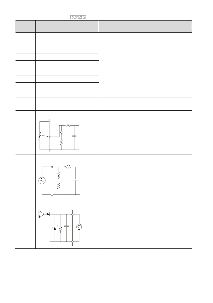
4.2 Parameter Settings for Applications
Speed Search
Applications Purpose Functions
Windmill, winding
machine, fan and all
inertia loads
DC Braking before Running
Applications Purpose Functions
When e.g. windmills,
fans and pumps rotate
freely by wind or flow
without applying power
Energy Saving
Applications Purpose Functions
Punching machines
fans, pumps and
precision machinery
Multi-step Operation
Applications Purpose Functions
Conveying machinery
Restart freerunning motor
Keep the freerunning motor at
standstill.
Energy saving and
less vibrations
Cyclic operation by
multi-step speeds.
Before the free-running motor is
completely stopped, it can be restarted
without detection of motor speed. The
AC motor drive will auto search motor
speed and will accelerate when its
speed is the same as the motor speed.
If the running direction of the freerunning motor is not steady, please
execute DC braking before start-up.
Energy saving when the AC motor
drive runs at constant speed, yet full
power acceleration and deceleration
For precision machinery it also helps
to lower vibrations.
To control 7-step speeds and duration
by simple contact signals.
Related
Parameters
Pr.32~Pr.35
Related
Parameters
Pr.28
Pr.29
Related
Parameters
Pr.95
Related
Parameters
Pr.17~Pr.23
Pr.78~Pr.79
Pr.81~Pr.87
4-14 Revision May 2008, ME14, SW V3.04
Page 50

Chapter 4 Parameters|
Switching acceleration and deceleration time
Applications Purpose Functions
Auto turntable for
conveying machinery
Switching
acceleration and
deceleration time
by external signal
When an AC motor drive drives two or
more motors, it can reach high-speed
but still start and stop smoothly.
Related
Parameters
Pr.10~Pr.13
Pr.39~Pr.42
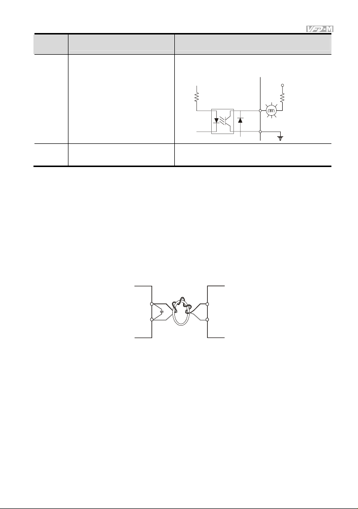
Overheat Warning
Applications Purpose Functions
When AC motor drive overheats, it
Air conditioner Safety measure
uses a thermal sensor to have
overheat warning.
Related
Parameters
Pr.45~Pr.46
Pr.39~Pr.42
Two-wire/three-wire
Applications Purpose Functions
M0 "Open": Stop, "Close": FWD Run
M1 "Open": Stop, "Close":REV Run
GND
M0 "Open": Stop, "Close": Run
M1 "Open": FWD, "Close":REV
GND
3-wire
M0 Run command, Runs w hen "close"
M2 Stop command, stops when "Open"
M1 REV/FWD Run selecti on
"Open": FWD Run
"Close": REV Run
GND
General application
To run, stop,
forward and
reverse by external
terminals
FWD/STOP
REV/STOP
RUN/STOP
REV/FWD
STOP RUN
FWD/REV
Related
Parameters
Pr.01
Pr.38
Operation Command
Applications Purpose Functions
General application
Selecting the
source of control
signal
Selection of AC motor drive control by
external terminals or digital keypad.
Related
Parameters
Pr.01
Pr.39~Pr.42
Revision May 2008, ME14, SW V3.04 4-15
Page 51

Chapter 4 Parameters|
Frequency Hold
Applications Purpose Functions
General application
Acceleration/
deceleration pause
Hold output frequency during
Acceleration/deceleration
Auto Restart after Fault
Applications Purpose Functions
Air conditioners,
remote pumps
For continuous and
reliable operation
without operator
intervention
The AC motor drive can be
restarted/reset automatically up to 10
times after a fault occurs.
Emergency Stop by DC Braking
Applications Purpose Functions
AC motor drive can use DC braking
High-speed rotors
Emergency stop
without brake
resistor
for emergency stop when quick stop is
needed without brake resistor. When
used often, take motor cooling into
consideration.
Over-torque Setting
Applications Purpose Functions
The over-torque detection level can be
set. Once OC stall, OV stall and overtorque occurs, the output frequency
will be adjusted automatically. It is
suitable for machines like fans and
pumps that require continuous
Pumps, fans and
extruders
To protect
machines and to
have continuous/
reliable operation
operation.
Upper/Lower Limit Frequency
Applications Purpose Functions
When user cannot provide
upper/lower limit, gain or bias from
external signal, it can be set
individually in AC motor drive.
Pump and fan
Control the motor
speed within
upper/lower limit
Related
Parameters
Pr.39~Pr.42
Related
Parameters
Pr.72
Pr.113
Related
Parameters
Pr.28
Pr.30
Pr.31
Related
Parameters
Pr.60~Pr.62
Related
Parameters
Pr.36
Pr.37
4-16 Revision May 2008, ME14, SW V3.04
Page 52

Chapter 4 Parameters|
Skip Frequency Setting
Applications Purpose Functions
The AC motor drive cannot run at
Pumps and fans
To prevent
machine vibrations
constant speed in the skip frequency
range. Three skip frequency ranges
Related
Parameters
Pr.67~Pr.70
can be set.
Carrier Frequency Setting
Applications Purpose Functions
The carrier frequency can be
General application Low noise
increased when required to reduce
Related
Parameters
Pr.71
motor noise.
Keep Running when Frequency Command is Lost
Applications Purpose Functions
When the frequency command is lost
Air conditioners
For continuous
operation
by system malfunction, the AC motor
drive can still run. Suitable for
Related
Parameters
Pr.63
intelligent air conditioners.
Output Signal in Zero Speed
Applications Purpose Functions
When the output frequency is lower
General application
Provide a signal for
running status
than the min. output frequency, a
signal is given for external system or
Related
Parameters
Pr.45
Pr.46
control wiring.
Output Signal at Master Frequency
Applications Purpose Functions
When the output frequency is at the
General application
Provide a signal for
running status
master frequency (by frequency
command), a signal is given for
external system or control wiring
Related
Parameters
Pr.45
Pr.46
(frequency attained).
Revision May 2008, ME14, SW V3.04 4-17
Page 53

Chapter 4 Parameters|
Output signal for Over-torque
Applications Purpose Functions
Pumps, fans and
extruders
To protect
machines and to
have continuous/
reliable operation
When over-torque is detected, a
signal is given to prevent machines
from damage.
Output Signal for Low Voltage
Applications Purpose Functions
General application
Provide a signal for
running status
When low voltage is detected, a signal
is given for external system or control
wiring.
Output Signal at Desired Frequency
Applications Purpose Functions
When the output frequency is at the
General application
Provide a signal for
running status
desired frequency (by frequency
command), a signal is given for
external system or control wiring
(frequency attained).
Output Signal for Base Block
Applications Purpose Functions
General application
Provide a signal for
running status
When executing Base Block, a signal
is given for external system or control
wiring.
Overheat Warning for Heat Sink
Applications Purpose Functions
When heat sink is overheated, it will
General application For safety
send a signal for external system or
control wiring.
Related
Parameters
Pr.45
Pr.46
Pr.61
Pr.62
Related
Parameters
Pr.45
Pr.46
Related
Parameters
Pr.45~Pr.46
Pr.47
Related
Parameters
Pr.45
Pr.46
Related
Parameters
Pr.45
Pr.46
4-18 Revision May 2008, ME14, SW V3.04
Page 54

Chapter 4 Parameters|
Multi-function Analog Output
Applications Purpose Functions
The value of frequency, output
General application
Display running
status
current/voltage can be read by
connecting a frequency meter or
Related
Parameters
Pr.43
Pr.44
voltage/current meter.
Revision May 2008, ME14, SW V3.04 4-19
Page 55

Chapter 4 Parameters|
4.3 Description of Parameter Settings
This parameter can be set during operation.
Pr.00
Source of Frequency Command
Factory Setting: 00
Settings 00 Master Frequency determined by digital keypad. (LC-M02E)
01 Master frequency determined by 0 to +10 V input
02 Master frequency determined by 4 to 20mA input
03 Master frequency determined by RS-485 Communication port
04 Master frequency determined by potentiometer on digital keypad.
(LC-M02E)
Pr.01
Source of Operation Command
Factory Setting: 00
Settings 00 Operation instructions determined by the Digital Keypad.
01 Operation instructions determined by the External Control Terminals.
02 Operation instructions determined by the External Control Terminals.
03 Operation instructions determined by the RS-485 communication port.
04 Operation instructions determined by the RS-485 communication port.
Refer to Pr.38 to Pr.42 for more details.
Pr.02
Stop Method
Factory Setting: 00
Settings 00 Ramp to stop
01 Coast to stop
This parameter determines how the motor is stopped when the AC drive receives a valid stop
command.
1. Ramp: The AC drive decelerates the motor to Minimum Output Frequency (Pr.08) and
2. Coast: The AC drive will stop the output instantly, and the motor will coast to stop.
Keypad STOP key is effective.
Keypad STOP key is not effective.
Keypad STOP key is effective.
Keypad STOP key is not effective.
then stops according to the deceleration time set in Pr.11 or Pr.13.
4-20 Revision May 2008, ME14, SW V3.04
Page 56

Chapter 4 Parameters|
Freq.
Hz
Hz
Freq.
Operation
command
Motor
Speed
Stops according
to deceleration
time
ON
OFF
Ramp
Time
Motor
Speed
ON
OFF
Coast
Free running
to stop
Time
Note: The motor stop method is usually determined by the application or system requirements.
Pr.03
Maximum Output Frequency
Unit: 0.1Hz
Settings 50.00 to 400.0 Hz Factory Setting: 60.00
This parameter determines the AC drive’s Maximum Output Frequency. All the AC drive
analog inputs (0 to +10V, 4 to 20mA) are scaled to correspond to the output frequency range.
Pr.04
Maximum Voltage Frequency (Base Frequency)
Unit: 0.1Hz
Settings 10.00 to 400.0Hz Factory Setting: 60.00
This parameter should be set according to the rated frequency as indicated in the motor
nameplate. Pr.04 and Pr.03 determine the volts per hertz ratio.
For example: if the drive is rated for 460 VAC output and the Maximum Voltage Frequency is set to
60Hz, the drive will maintain a constant ratio of 7.66 v/Hz. Setting of Pr.04 must be equal to or
greater than setting of Mid-Point Frequency (Pr.06).
Pr.05
Maximum Output Voltage (Vmax)
Settings 115V/230V series 0.1 to 255.0V Factory Setting: 220.0
460V series 0.1 to 510.0V Factory Setting: 440.0
575V series 0.1 to 637.0V Factory Setting: 575.0
This parameter determines the Maximum Output Voltage of the AC drive. The Maximum
Output Voltage setting must be smaller than or equal to the rated voltage of the motor as
indicated on the motor nameplate. Setting of Pr.05 must be equal to or greater than setting
of Mid-Point Voltage (Pr.07).
Revision May 2008, ME14, SW V3.04 4-21
Page 57

Chapter 4 Parameters|
Pr.06
Mid-Point Frequency
Unit: 0.1Hz
Settings 0.10 to 400.0Hz Factory Setting: 1.50
The parameter sets the Mid-Point Frequency of V/F curve. With this setting, the V/F ratio
between Minimum Frequency and Mid-Point frequency can be determined. Setting of this
parameter must be equal to or greater than Minimum Output Frequency (Pr.08) and
equal to or less than Maximum Voltage Frequency (Pr.04).
Pr.07
Mid-Point Voltage
Settings 115V/230V series 0.1 to 255.0V Factory Setting: 10.0
460V series 0.1 to 510.0V Factory Setting: 20.0
575V series 0.1 to 637.0V Factory Setting: 26.1
The parameter sets the Mid-Point Voltage of any V/F curve. With this setting, the V/F ratio
between Minimum Frequency and Mid-Point Frequency can be determined. Setting of this
parameter must be equal to or greater than Minimum Output Voltage (Pr.09) and equal
to or less than Maximum Output Voltage (Pr.05).
Pr.08
Minimum Output Frequency
Unit: 0.1Hz
Settings 0.10 to 20.00Hz Factory Setting: 1.50
The parameter sets the Minimum Output Frequency of the AC drive. Setting of this
parameter must be equal to or less than Mid-Point Frequency (Pr.06).
Pr.09
Minimum Output Voltage
Settings 115V/230V series 0.1 to 255.0V Factory Setting: 10.0
460V series 0.1 to 510.0V Factory Setting: 20.0
575V series 0.1 to 637.0V Factory Setting: 26.1
This parameter sets the Minimum Output Voltage of the AC drive. Setting of this parameter
must be equal to or less than Mid-Point Voltage (Pr.07).
Volt age
Pr.05
Pr.07
Pr.09
0
Pr.06
Pr.08
Pr.03
Pr.04
Frequency
4-22 Revision May 2008, ME14, SW V3.04
Page 58

Chapter 4 Parameters|
Vol tag e
Pr.05
Pr.07
Pr.09
Commonly used V/F Setting
(1) General Purpose
Motor Spec. 60Hz
V
220
10
1.5
Pr.08 Pr.06 Pr.04 Pr.03
Custom V/F Curve
Vol tag e
Pr.05
Pr.07
Pr.09
Pr.08
Factory Settings
60.0 f
Pr.06 Pr.04
Fan/Pump V/F Curve
Set value
No.
60.0
Pr.03
60.0
Pr.04
220.0
Pr.05
1.5
Pr.06
10.0
Pr.07
Pr.08
1.5
Pr.09
10.0
Frequenc y
Frequency
Pr.03
Motor Spec. 50Hz
V
220
10
1.5
50.0 f
Set value
No.
Pr.03
50.0
50.0
Pr.04
Pr.05
220.0
Pr.06
Pr.07
Pr.08
Pr.09
1.3
12.0
1.3
12.0
Revision May 2008, ME14, SW V3.04 4-23
Page 59

Chapter 4 Parameters|
(2) Fans and Pumps
Motor Spec. 60Hz
V
220
50
10
1.5
30
60.0f
Factory Settings
No.
Set value
60.0
Pr.03
Pr.04
60.0
220.0
Pr.05
30
Pr.06
50.0
Pr.07
Pr.08 1.5
10.0
Pr.09
Motor Spec. 50Hz
V
220
50
10
1.3
25
50.0f
No.
Set value
50.0
Pr.03
Pr.04
50.0
220.0
Pr.05
25
Pr.06
50.0
Pr.07
Pr.08 1.3
10.0
Pr.09
(3) High Starting Torque
Motor Spec. 60Hz
V
220
23
18
1.5
3
60.0f
Factory Settings
No.
Set value
60.0
Pr.03
Pr.04
60.0
220.0
Pr.05
3
Pr.06
23.0
Pr.07
Pr.08 1.5
18.0
Pr.09
Motor Spec. 50Hz
V
220
23
14
2.2
1.3
60.0f
No.
Set value
50.0
Pr.03
Pr.04
50.0
220.0
Pr.05
Pr.06
2.2
23.0
Pr.07
Pr.08 1.3
14.0
Pr.09
Pr.10
Acceleration Time 1
Pr.11
Deceleration Time 1
Pr.12
Acceleration Time 2
Pr.13
Deceleration Time 2
Unit: 0.1 or 0.01 sec
Unit: 0.1 or 0.01 sec
Unit: 0.1 or 0.01 sec
Unit: 0.1 or 0.01 sec
Settings 0.1 to 600.0 sec or 0.01 to 600.0 sec Factory Setting: 10.0
Pr.10. This parameter is used to determine the time required for the AC drive to ramp from 0
Hz to its Maximum Output Frequency (Pr.03). The rate is linear unless the S-Curve (Pr.14) is
“Enabled”.
Pr.11. This parameter is used to determine the time required for the AC drive to decelerate
from the Maximum Output Frequency (Pr.03) down to 0 Hz. The rate is linear unless the S-
Curve (Pr.14) is “Enabled”.
Pr.12 and Pr.13: Provide an additional Accel/Decel time although Time 1 is the default. A
Multi-Function input terminal must be programmed to select Accel/ or Decel/ Time 2 and the
terminal must be closed to select Accel/Decel Time 2 (See Pr.38 to Pr.42).
In the below diagram, suppose the Maximum Output Frequency is 60 Hz (Master Freq),
Minimum Output Frequency (start-up) is 1.0 Hz, and accel/decel time 1 is 10 seconds. The
actual time for the AC drive to accelerate from start-up to 60 Hz is 9.83 seconds (deceleration
time is also 9.83 seconds), can be determined by the formula.
4-24 Revision May 2008, ME14, SW V3.04
Page 60

Chapter 4 Parameters|
Frequency
Max.
Output
Freq.
Pr.10
or
Pr. 12
Accelera tion Time
Actual Accelerat ion/Deceleration Time=
Acceleration/Deceleration Time x(Master Freq.-Min.Output Freq.)
Time
Pr.11
or
Pr. 13
Deceler ation Time
Max. Output Freq.
Pr.14
Acceleration S-Curve
Settings 00 to 07 Factory Setting: 00
This parameter is used whenever the motor load needs to be accelerated or decelerated
smoothly. The desired accel/decel effect is selectable from 0 to 7, in which the larger the
number, the greater the effect achieved. If the default value of Pr.111 Deceleration S Curve is
unchanged (“0”), then Pr.14 sets both acceleration and deceleration S-Curves. If Pr.111 is set
to any value other than “0”, then Pr.14 will set the acceleration S-Curve and Pr.111 will set the
deceleration S-Curve.
Freq.
Acceleration/Deceleration characteristics
(1), (2) Disabling S curve
(3), (4) Enabling S curve
Pr.15
Jog Accel / Decel Time
Unit: 0.1 or 0.01 sec
Settings 0.1 to 600.0 sec or 0.01 to 600.0 sec Factory Setting: 1.0 sec
This parameter sets the acceleration or deceleration time for Jog operation.
Pr.16
Jog Frequency
Unit: 0.1 Hz
Settings 0.00 to 400.0 Hz Factory Setting: 6.00 Hz
Revision May 2008, ME14, SW V3.04 4-25
Page 61

Chapter 4 Parameters|
When the JOG function is activated, the AC drive will accelerate from Minimum Output
Frequency (Pr.08) to Jog Frequency (Pr.16). Drive must be in “stop” status for the operator to
activate the JOG function. Likewise, during Jog operation, other commands cannot be
accepted through the keypad but FORWARD, REVERSE and STOP. The JOG function can
be remotely activated when the Jog terminal is closed, and if the Jog terminal opens, the AC
drive will decelerate from Jog Frequency to zero. The accel / decel time is entered as Jog
Accel / Decel Time (Pr.15). Multi-function Input terminals (M1-M5) can also be used to initiate
the JOG operation if so programmed.
ON
Pr. 15
Deceleration Time
OFF
Time
Frequency
Jog
Freq.
Pr.16
Jog operation
command
Pr. 15
Acceleration Time
Pr.17
1st Step Speed Frequency
Pr.18
Pr.19
Pr.20
Pr.21
Pr.22
Pr.23
Step Speed Frequency
2nd
Step Speed Frequency
3rd
4th Step Speed Frequency
5th Step Speed Frequency
6th Step Speed Frequency
7th Step Speed Frequency
Unit: 0.1 Hz
Unit: 0.1 Hz
Unit: 0.1 Hz
Unit: 0.1 Hz
Unit: 0.1 Hz
Unit: 0.1 Hz
Unit: 0.1 Hz
Settings 0.00 to 400.0Hz Factory Setting: 0.00 Hz
Multi-Function Input Terminals (refer to Pr.38 to Pr.42) are used to select Multi-Step speeds.
The desired speed frequencies are entered in Pr.17 to Pr.23. When the associated multi-
function input terminal is closed, drive will run at one of these specific frequencies.
Multi-step speeds (Pr.17 to Pr.23), Pr.78, Pr.79, and Pr.81 to Pr.87; are used for multi-step
motion control, which is executed in an orderly manner, similar to a PLC program.
4-26 Revision May 2008, ME14, SW V3.04
Page 62

Chapter 4 Parameters|
Pr.24
Reverse Operation Inhibition
Factory Setting: 00
Settings 00 Enable REV operation
01 Disable REV operation
This parameter is used to disable motor rotation in reverse.
Pr.25
Over–Voltage Stall Prevention
Settings 115V/230V series 330-450Vdc Factory Setting: 390
460V series 660-900Vdc Factory Setting: 780
575V series 825-1025Vdc Factory Setting: 975
00 disable
During deceleration, the DC bus voltage may exceed its maximum allowable value due to
motor regeneration. When this function is enabled, the AC drive will stop decelerating, and
maintain a constant output frequency to prevent from over-voltage tripping. Drive will resume
deceleration when the voltage drops below the setting for Pr.25.
Note: In applications where inertia is low, over-voltage during deceleration would not occur. When
inertia is high, the AC drive will automatically extend the deceleration period. If a faster stop is
needed, then a dynamic brake resistor should be used.
DC bus voltage
Over-voltage
detection
level
output
Freq.
time
Over-voltage Stall Prevention
Pr.26
Over-Current Stall Prevention during Acceleration
Factory Setting: 150%
Settings 20 to 200%
00 disable
A setting of 100% is equal to the Rated Output Current of the drive.
Revision May 2008, ME14, SW V3.04 4-27
Unit: 1%
time
Page 63

Chapter 4 Parameters|
Under certain conditions, the AC drive output current may increase abruptly, and exceed the
value specified by Pr.26. This is commonly caused by rapid acceleration or excessive load on
the motor. When this function is enabled, the AC drive will stop accelerating and maintain a
constant output frequency. Drive will resume accelerating only after the current drops below
the setting for Pr.26.
Pr.27
Over-Current Stall Prevention during Operation
Unit: 1%
Factory Setting: 150%
Settings 20 to 200%
00: disable
During a steady-state operation with the motor load rapidly increasing, the AC drive output
current may exceed the limit specified in Pr.27. When this occurs, the output frequency will
decrease to maintain a constant motor speed. The drive will accelerate to the steady-state
output frequency only when the output current drops below the setting for Pr.27.
Output current
over-current
detection
level
output
frequency
time
output current
over-current
detection
level
Pr.27
output
freq.
time
time
over-cur rent Stall Preventio n
during Acce leration
time
Over-current Stall Prevention
during Operation
Pr.28
DC Braking Current Level
Unit: 1%
Settings 00 to 100% Factory Setting: 00
This parameter determines the amount of DC Braking Current applied to the motor during
starting and stopping. When setting the DC Braking Current, please note that 100%
corresponds to the rated current of the AC drive. It is recommended to start with a low DC
Braking Current level and then increase it until proper holding torque has been attained.
4-28 Revision May 2008, ME14, SW V3.04
Page 64

Chapter 4 Parameters|
Pr.29
DC Braking Time during Start-up
Unit: 0.1sec
Settings 0.0 to 5.0 sec Factory Setting: 0.0
This parameter determines the duration for the DC Braking Current applied during starting. DC
Braking is applied until the Minimum Frequency is reached.
Pr.30
DC Braking Time during Stopping
Unit: 0.1sec
Settings 0.0 to 25.0 sec Factory Setting: 0.0
This parameter determines the duration for the DC Braking voltage to be applied during
stopping. If stopping with DC Braking is desired, then Pr.02 must be set to Ramp to Stop (0.0).
Pr.31
Start-Point for DC Braking
Unit: 0.1sec
Settings 0.00 to 60.00Hz Factory Setting: 0.00
This parameter sets the frequency at which the DC Braking will begin during deceleration.
Master
Frequenc y
Pr.31
OFF
Start-po int
for DC
braking
Pr.30
time(s)
Min. output
Freq.
Operation
command
Pr.29
DC Braking Current %
ON
Pr.28
Notes:
1. DC Braking during starting is used for loads that may move before the AC drive starts, such
as hoists and cranes. These loads may also be moving in the wrong direction. Under such
circumstances, the DC Braking can be used to hold the load in position before applying a
forward motion.
2. DC Braking during stopping is used to stop faster than the ramp-to-stop or to hold a
stopped load in position. A dynamic brake resistor may be needed in order to stop loads of
high inertia.
Revision May 2008, ME14, SW V3.04 4-29
Page 65

Chapter 4 Parameters|
Pr.32
Momentary Power Loss Operation Selection
Factory Setting: 00
Settings 00 Operation stops after momentary power loss
01 Operation continues after momentary power loss Speed search starts with
the Master Frequency reference value
02 Operation continues after momentary power loss Speed search starts with
the min frequency
Pr.33
Maximum Allowable Power Loss Time
Unit: 0.1sec
Settings 0.3 to 5.0 sec Factory Setting: 2.0 sec
After a power loss, the AC drive will resume operation only if the power loss duration is shorter
than the time defined by Pr.33. If the Maximum Allowable Power Loss Time is exceeded, the
AC drive output is then turned off.
Pr.34
Base-Block Time for Speed Search
Unit: 0.1sec
Settings 0.3 to 5.0 sec Factory Setting: 0.5 sec
When a momentary power loss is detected, the AC drive will stop its output and will wait during
a specified time interval called Base Block (entered in Pr.34) before resuming operation.
Setting of this parameter should make the residual output voltage due to regeneration almost
zero, before the drive resumes operation.
This parameter also determines the search time when performing external Base-Block and
Fault Reset (Pr.72).
Pr.35
Maximum Current Level for Speed Search
Unit: 1%
Settings 30 to 200% Factory Setting: 150
Following a power failure, the AC drive will start its speed search operation only if the output
current is greater than the value determined by Pr.35. When the output current is less than that
of Pr.35, the AC drive output frequency is at a “speed synchronization point” and will
accelerate or decelerate back to the operating frequency at which it was running prior to the
power failure.
4-30 Revision May 2008, ME14, SW V3.04
Page 66

Chapter 4 Parameters|
Allowable Max. Power Loss Time
Input
Power
Output
Power
Pr.33
Pr.32=1
Speed search sta rts with
the Master Freque ncy
speed synchronization
detection
Allowable Max. power loss time
Pr.33
Speed search sta rts with
minimum output freque ncy
Pr.32=2
Output
Vol tag e
Baseblock
Time
Pr.34
speed search
Baseblock
Time
Pr.34
Pr.36
Upper Bound of Output Frequency
Unit: 0.1Hz
Settings 0.10 Hz to 400.0 Hz Factory Setting: 400
The Upper/Lower Bounds help prevent operation error and machine damage.
If the Upper Bound of Output Frequency is 50Hz and the Maximum Output Frequency is 60Hz,
the Maximum Output Frequency will be limited to 50Hz.
Setting of this parameter must be equal to or greater than the Lower Bound of Output
Frequency (Pr.37).
Pr.37
Lower Bound of Output Frequency
Unit: 0.1Hz
Settings 0.00 Hz to 400.0 Hz Factory Setting: 0 Hz
Setting of this parameter must be equal to or less than the Upper Bound of Output Frequency
If the Lower Bound of Output Frequency is 10Hz, and the Minimum Output Frequency (Pr.08)
is set at 1.0Hz, then any command frequency between 1-10Hz will generate a 10Hz output
from the drive.
output frequency
Pr.36
Pr.37
Input Freq.
Revision May 2008, ME14, SW V3.04 4-31
Page 67

Chapter 4 Parameters|
Pr.38
Multi-function Input Terminal (M0, M1)
Factory Setting: 00
Settings 00 M0: FWD/STOP, M1: REV/STOP
01 M0: RUN/STOP, M1: REV/FWD
02 M0, M1, M2: 3-wire operation control mode
Explanations:
00: Two wire operation: Only Pr.38 can be set to “0”.
FWD/STOP
M0 "Open": Stop, "Close" : FWD Run
REV/STOP
M1 "Open": Stop, "Close":REV Run
GND
01: Two wire operation: Only Pr.38 can be set to “1”.
RUN/STOP
REV/FWD
M0 "Open": Stop, "Close": Run
M1 "Open": FWD, "Close":REV
GND
Note: Multi-function Input Terminal M0 does not have its own parameter designation. M0 must be
used in conjunction with M1 to operate two and three wire control.
02 Three Wire Control: Only Pr.38 can be set to “2”.
STOP RUN
M0 Run command, Runs when "close"
M2 Stop command, stops when "Open"
M1 REV/FWD Run sele ction
FWD/REV
"Open": FWD Run
"Close": REV Run
GND
Note: When the “2” setting is selected for Pr.38, the value in Pr.39 will be ignored.
4-32 Revision May 2008, ME14, SW V3.04
Page 68

Chapter 4 Parameters|
Pr.39
Multi-function Input Terminal (M2)
Factory Setting: 05
Pr.40
Multi-function Input Terminal (M3)
Factory Setting: 06
Pr.41
Multi-function Input Terminal (M4)
Factory Setting: 07
Pr.42
Multi-function Input Terminal (M5)
Factory Setting: 08
Settings 00 to 32
Settings Function Description
No Function
00
Output OFF (N.O.)
01
(enabled when running)
When it is set to 01 or 02, AC drive output will stop
immediately. If there is start signal after stopping, the output
Output OFF (N.C.)
02
(enabled when running)
will start from the minimum frequency.
03 External Fault (N.O.)
Parameter values 3 and 4 program Multi-Function Input
Terminals: M1 (Pr.38), M2 (Pr.39), M3 (Pr.40), M4 (Pr.41) or
M5 (Pr.42) to be External Fault (E.F.) inputs.
04 External Fault (N.C.)
E.F.(N.O.)
setting by 3
E.F(N.C.)
setting by 4
Mx "Close": Operat ion availabl e.
Mx "Open":Operation available.
GND
Note: When an External Fault input signal is received, the AC
drive output will turn off, drive will display “ E.F.” on
Digital Keypad, and the motor will coast. Normal
operation can resume after the External Fault is cleared
and the AC drive is reset.
Revision May 2008, ME14, SW V3.04 4-33
Page 69

Chapter 4 Parameters|
d
Settings Function Description
Parameter value 5 programs Multi-Function Input Terminals:
M1 (Pr.38), M2 (Pr.39), M3 (Pr.40), M4 (Pr.41) or M5 (Pr.42)
to be an External Reset.
RESET
setting by 5
05 External Reset
Mx "Close": Operation avalilable
GND
Note: The External Reset has the same function as the Reset
key on the Digital keypad. It will reset the drive after a
fault.
Multi-Step Speed
06
Command 1
Multi-Step Speed
07
Command 2
Multi-Step Speed
08
Command 3
Parameter values 06, 07,and 08 program any three of the
following Multi-Function Input Terminals: M1 (Pr.38), M2
(Pr.39), M3 (Pr.40), M4 (Pr.41) or M5 (Pr.42) for Multi-step
Speed Command function.
d6 Multi-step 1
d7 Multi-st ep 2
d8 Multi-st ep 3
Mx "Close": Operation available
Mx "Close": Operation available
Mx "Close": Operation available
GND
Note: These three inputs select up to seven multi-step speeds
defined by Pr.17 to Pr.23 as shown in the following
diagram. Pr.78 to Pr.87 can also control output speed
by programming the AC drive’s internal PLC function.
Pr.17
Master Freq.
Mx1-GND
Mx2-GND
Mx3-GND
Operation
Comman
Freq.
Step 1
ON
Pr.18
Step 2
ON
ON ON
Pr.19
Step 3
Pr.20
Step 4
ON
ON
Pr.21
Step 5
Pr.22
Step 6
ON ON
ON ON
ON ON ON
Pr.23
Step 7
OFF
Time
4-34 Revision May 2008, ME14, SW V3.04
Page 70

Chapter 4 Parameters|
Settings Function Description
Parameter value 09 programs Multi-Function Input Terminal:
M1 (Pr.38), M2 (Pr.39), M3 (Pr.40), M4 (Pr.41) or M5 (Pr.42)
for Jog control.
09 Jog Operation
Accel/Decel Speed
10
Inhibit
9 jog o pera tion
command
Mx "Close": Operation available
GND
Note: Jog operation programmed by 9 can only be initiated
while the motor is stop. (Refer to Pr.15, Pr.16.)
Parameter value 10 programs Multi-Function Input Terminal:
M1 (Pr.38), M2 (Pr.39), M3 (Pr.40), M4 (Pr.41) or M5 (Pr.42)
for Accel/Decel Inhibit. After receiving this command, the AC
Drive stops accelerating or decelerating and maintains a
constant speed.
ON
Decel
inhibit
Decel
inhibit
Time
ON ON
OFF
Frequenc y
Mx-GND
Operation
command
Master Frequency
Accel inhibit
Accel inhibi t
Actual oper ation frequenc y
ON ON
Revision May 2008, ME14, SW V3.04 4-35
Page 71

Chapter 4 Parameters|
(
)
Settings Function Description
Parameter value 11 programs a Multi-Function Input
Terminal: M1 (Pr.38), M2 (Pr.39), M3 (Pr.40), M4 (Pr.41) or
M5 (Pr.42) for selecting the First or Second Accel/Decel time.
(Refer to Pr.10 to Pr.13.)
Mx "Close": 2nd Accel/Decel
First or Second
11
Accel/Decel Time
Selection
External Base Block
(N.O.)
12
(Normally Open Contact
Input)
Mx set 11
Frequency
Master
Frequency
Pr.10
Mx-GND
operation
command
Parameter values 12, 13 program Multi-Function Input
Terminals: M1 (Pr.38), M2 (Pr.39), M3 (Pr.40), M4 (Pr.41) or
M5 (Pr.42) for external Base Block control. Value 12 is for
normally open (N.O.) input, and value 13 is for a N.C. input.
B.B.
setting by 12
B.B.(N.C.)
setting by 13
"Open": 1st Accel/Decel
GND
Pr.11 Pr.12
1st
Accel/
Decel
ON
N.O.
2nd
Accel/
Decel
ON
ON
Mx "Close": Operation available.
Mx "Open":Operation available.
GND
Pr.13 Pr.10
Note: When a Base-Block signal is received, the AC drive will
stop all output and the motor will coast. When base
External Base Block
(N.C.)
13
(Normally Close Contact
Input)
block control is deactivated, the AC drive will start its
speed search function and synchronize with the motor
speed, and then accelerate to the Master Frequency.
External
base-block
signal
Output
frequency
Output
voltage
Capacitor
dischar ge
Allowable max. power loss time
Pr.33
Pr.32=1
Speed search starts with the
reference value
Low voltage
Min. base-block time
Low voltage
Pr.34
Pr.13
2nd
1st
Decel
Accel
ON
ON
OFF
Speed synchronization
detection
Speed search op eration
Time
4-36 Revision May 2008, ME14, SW V3.04
Page 72

Chapter 4 Parameters|
Settings Function Description
Increase Master
14
Frequency
Decrease Master
15
Frequency
16 Run PLC Program
17 Pause PLC Program
Parameter values 14, 15 program the Multi-Function Input
Terminals: M1 (Pr.38), M2 (Pr.39), M3 (Pr.40), M4 (Pr.41) or
M5 (Pr.42) to incrementally increase/ decrease the Master
Frequency each time an input is received.
UP
setting by 14
DOWN
setting by 15
Mx " Clo se" : Freq . wil l in cre as e
by one unit.
Mx "Open":Freq. will decrease
b y one un it.
GND
Parameter value 16 programs Multi-Function Input Terminal:
M1 (Pr.38), M2 (Pr.39), M3 (Pr.40), M4 (Pr.41) or M5 (Pr.42)
to enable the AC drive internal PLC program. Parameter
value 17 programs an input terminal to pause the PLC
program.
PLC operation
setting by 16
setting by 17
Mx "Close": Run PLC.
Mx "Open":Pause PLC.
GND
Note: Pr.17 to Pr.23, Pr.78, Pr. 79, Pr.81 to Pr.87 define the
PLC program. Another related function is “30 One-Shot
PLC Run”. It can be set to use a not-latched contact as
the run signal.
Revision May 2008, ME14, SW V3.04 4-37
Page 73

Chapter 4 Parameters|
Settings Function Description
Parameter value 18 programs Multi-Function Input Terminal:
M1 (Pr.38), M2 (Pr.39), M3 (Pr.40), M4 (Pr.41) or M5 (Pr.42)
to increase the AC drive’s internal counter. When an input is
received, the counter is increased by 1.
Trigger
18 counter
trigger signal
input.
Mx counter value increase by
1 when closed.
GND
Note: The Counter Trigger input can be connected to an
18 Counter Trigger Signal
external Pulse Signal Generator when counting a
process step or unit of material. See the diagram
below.
Indication value
(Pr.64=1)
Counter trigger signal
Multi-function input terminal
(Pr.38 to Pr.42 =18)
Signal output with Pr.97
counter value is attained.
(Pr.97=3)
(Pr.45/46=13)
2ms
The trigger timing
can't be less than
2ms.(<250Hz)
2ms
Signal output with Pr.96
counter value is attained.
(Pr.96=5)
(Pr.45/46=14)
Parameter value 19 programs Multi-Function Input Terminal:
M1 (Pr.38), M2 (Pr.39), M3 (Pr.40), M4 (Pr.41) or M5 (Pr.42)
to reset the counter.
19 Counter Reset
Reset counter
19 r eset t he
counter value.
Mx "close": reset count er.
GND
Enter value (20) to disable any Multi-Function Input Terminal:
M1 (Pr.38), M2 (Pr.39), M3 (Pr.40), M4 (Pr.41) or M5 (Pr.42)
20 No Function
4-38 Revision May 2008, ME14, SW V3.04
Note: Purpose of this function is to isolate unused Multi-
Function Input Terminals. Any unused terminals should
be programmed to 20 to insure they have no effect on
drive operation.
Page 74

Chapter 4 Parameters|
Settings Function Description
21 RESET Command (N.C)
Control source: External
22
Terminal
23 Control source: Keypad
Control source:
24
Communication
Parameter Lock (Write
25
disable, Read is always
0)
26 PID Disable (N.O.)
27 PID Disable (N.C.)
28 Second Source for
Frequency Command
29 Forward (contact is
open) / Reverse (contact
is close)
30 One-Shot PLC Run
Enter values 22, 23, or 24 to set the control source to be the
external terminals, keypad or communication respectively.
This setting is used to create functions for manual/auto, and
remote/near-end control. When these three functions are
used at the same time, the priority is 22-I/O > 23-Keypad >
24-Communication.
This function will disable the write function and all the content
of read are 0. The application is for customer having a key to
control the operator to modify parameters or modify the
parameter by improper use.
This function pause the PID control. It is commonly used for
manual operation or function testing, and to recover the PID
function when the system is normal.
This function is used with Pr. 142 to select a different
frequency source for control.
This function has top priority to set the direction for running (If
“Pr. 24 inhibit REV function” is not set). No mater what the
present direction of run is, the contact N.O. is forward and the
contact N.C. is reverse, once this function is set.
The requirement for setting direction is Pr. 24 > setting 29 of
Pr. 39-Pr. 42 > Pr. 38.
31 Index Input Signal
32 Virtual Timer Input
Note: The settings 00~32 in Pr. 39 to Pr.42 can be used to set multi-function terminals (M2-M5) but
the settings cannot be used repeatedly at the same time (besides settings 20).
Revision May 2008, ME14, SW V3.04 4-39
This function is used with parameters 149 to 151. The position
where AC drive stops will be regarded as the zero position
and it will move to the angle that Pr. 150 sets.
This function is for counting at the speed of the output
frequency.
Page 75

Chapter 4 Parameters|
Pr.43
Analog Output Signal
Factory Setting: 00
Settings 00 Analog Frequency Meter (0 to Maximum Output Frequency)
01 Analog Current Meter (0 to 250% of the rated AC drive current)
02 Feedback Signal (0 - 100%)
03 Output Power (0 - 100%)
This parameter selects if the Output Frequency, Current, PID feedback or Output Power will be
the output signal on the AFM terminal (0 to 10V).
Pr.44
Analog Output Gain
Unit: 1%
Settings 00 to 200% Factory Setting: 100
This parameter sets the voltage range of the analog output signal on output terminal AFM.
AFM
GND
AFM
GND
+-
Analog Frequency Meter
+-
Analog Current Meter
The analog output voltage is directly proportional to the output frequency of the AC drive. A setting of
100% on Pr.44 makes the Maximum Output Frequency (Pr.03) of the AC drive to correspond to the
+10VDC analog voltage output. (The actual voltage is about +10VDC, and can be adjusted by Pr.44)
The analog output voltage is also directly proportional to the output current of the AC drive. A setting
of 100% on Pr.44 makes the 2.5 times rated current of the AC drive to correspond to the +10 VDC
analog voltage output. (The actual voltage is about +10 VDC, and can be adjusted by Pr.44)
Note: Any type of voltmeter can be used. If the meter reads full scale at a voltage less than 10 volts,
then Pr.44 should be set by the following formula:
Pr.44 = ((meter full scale voltage)/10)×100%
For Example: When using a meter with a full scale of 5 volts, adjust Pr.44 to 50%
4-40 Revision May 2008, ME14, SW V3.04
Page 76

Chapter 4 Parameters|
Pr.45
Multi-function Output Terminal 1 (Photocoupler output)
Factory Setting: 00
Pr.46
Multi-function Output Terminal 2 (Relay output)
Factory Setting: 07
Settings 00 to 24
Settings Function Description
00 AC Drive Operational
Maximum Output
01
Frequency Attained
02 Zero speed
Terminal output is activated when there is power output
from drive.
Terminal output is activated when the AC drive attains
Maximum Output Frequency.
Terminal output is activated when Command Frequency is
lower than the Minimum Output Frequency.
Terminal output is activated when over-torque is detected.
03 Over-Torque detection
Parameter Pr.61 determines the Over-Torque detection
level.
Base-Block (B.B.)
04
Indication
Terminal output is activated when the AC drive output is
shut-off by the external Base-Block.
05 Low-Voltage Indication Terminal output is activated when low voltage is detected.
06 AC Drive Operation Mode
07 Fault Indication
Desired Frequency
08
attained
09 PLC Program Running
PLC Program Step
10
Completed
11 PLC Program Completed
Terminal output is activated when the operation of AC Drive
is controlled by External Control Terminals.
Terminal output is activated when certain faults occur (oc,
ov, oH, oL, oL1, EF, cF3, HPF, ocA, ocd, ocn, GF).
Terminal output is activated when the desired frequency
(Pr.47) is attained.
Terminal output is activated when the PLC program is
running.
Terminal output is activated for 0.5 sec. when each multi-
step speed is attained.
Terminal output is activated for 0.5 sec. when the PLC
program cycle has completed.
12 PLC Operation Paused Terminal output is activated when PLC operation is paused.
13 Top Count Value Attained
Terminal output is activated when counter reaches the Top
Count Value. See diagram for Pr.38 to Pr.42=18.
Revision May 2008, ME14, SW V3.04 4-41
Page 77

Chapter 4 Parameters|
Settings Function Description
Preliminary Counter Value
14
Attained
Warning (PID feedback
15
loss, communication error)
Below the Desired
16
Frequency
17 PID supervision
Terminal output is activated when counter reaches the
Preliminary Count Value. See diagram for Pr.38 to
Pr.42=18.
The contact will be “close” when PID feedback loss or
communication is error.
The contact will be “close” when output frequency is less
than desired frequency.
The contact will be “close” when PID offset exceeds the
setting of P126 and P127.
The contact will be “close” before over voltage. It will be
18 Over Voltage supervision
activated at 370Vdc in 230V series and at 740Vdc in 460
series.
19 Over Heat supervision The contact will be “close” before 90°C.
Over Current stall
20
supervision
Over Voltage stall
21
supervision
The contact will be “close” before exceeding the setting of
P26/P27.
The contact will be “close” before exceeding the setting of
P25.
22 Forward command The contact will be “close” with forward command.
23 Reverse command The contact will be “close” with reverse command.
Zero Speed (Includes
24
Drive Stop)
Multi-function indication
output terminals.
AC 250V 2A
DC 30V 2A
Multi-function PHC
output terminals.
PHC
480VDC 50mA
The contact will be “close” when the setting frequency is
less than min. frequency or drive stop.
Power source
AC/DC
Faults indica tion.
RA
RB
RC
MO1
MCM
Power indicat ion.
BZ
LT
LT
Pre-s et f req. at ta in ed
Plus terminals
Power 48VDC
50mA
Minus terminal
4-42 Revision May 2008, ME14, SW V3.04
Page 78

Chapter 4 Parameters|
Pr.47
Desired Frequency Attained
Unit: 0.1Hz
Settings 0.00 to 400.0 Hz Factory Setting: 0.00
This parameter allows monitoring a certain frequency and then activates one of the Multi-
function output terminals (Pr.45 or Pr.46 set to 8) when that frequency is achieved.
Freq.
Max. Output
Freq.
Desired Freq.
Detecti on range
+
2Hz
-
Pr.47
Preset Freq.
Attained
Indication
Pr.45 to
Pr.46
Desired Freq.
Attained
Indication
Pr.45 & Pr.46
OFF
OFF
ON
ON
Desired Freq. Attained & Preset Freq. Attained
Detecti on
range
+
4Hz
-
Detecti on
range
-2Hz
Time
OFF
OFF
Pr.48
Adjust Bias of External Input Frequency
Unit: 0.1Hz
Settings 0.00 to 200.0% Factory Setting: 0.00 Hz
This parameter provides a frequency offset when the source of frequency command is the
analog input.
Pr.49
Potentiometer Bias Polarity
Factory Setting: 00
Settings 00 Positive Bias
01 Negative Bias
This parameter sets the potentiometer Bias Frequency to be positive or negative.
Pr.50
Potentiometer Frequency Gain
Unit: 1%
Settings 0.10 to 200.0% Factory Setting: 100.0
This parameter sets the ratio of analog input vs frequency output.
Pr.51
Potentiometer Reverse Motion Enable
Factory Setting: 00
Settings 00 Reverse Motion Disabled in negative bias
01 Reverse Motion Enabled in negative bias
Revision May 2008, ME14, SW V3.04 4-43
Page 79

Chapter 4 Parameters|
A
A
A
A
Pr.48 to Pr.51 are used when the source of frequency command is the analog signal (0 to
+10V DC or 4 to 20mA DC). Refer to the following examples.
Example 1:
Set Pr.00=1 to command frequency with the potentiometer on keypad or Pr.00=2 (4 to 20mA current
signal) potentiometer/current signal of external terminal.
Max.
Output
Freq.
60Hz
0Hz
0V
4mA
Pr.03
5V
12m
Pr.03=60Hz--Max. output Freq.
Pr.48=0%--bias adjustment
Pr.49=0 -- bias polarity
Pr.50=100% -- pot. freq. gain
Pr. 51 =0 - - REV dis ab le i n
negative bias
10V
20m
Factory Settings
30
0
0V
60
Hz
10V
Potentiometer Scale
Example 2:
A Bias Adjustment (16.7% of 60Hz) determines the Output Frequency to be 10 Hz with the
potentiometer set at 0V as shown. Notice that the entire V/F is transposed accordingly. An analog
input voltage 0-8.33V (or current 4-13.33mA) would set frequency as 0-60Hz.Once the Maximum
Output Frequency is reached any further increase on the potentiometer will not increase output
frequency (If you want to use the range of 60Hz, please refer to the example 3).
Max.
Output
Pr.03
Freq.
10Hz
B ias
Adjustment
60Hz
0Hz
0V
4mA
5V
12m
Pr.03=60Hz--Max. output Freq.
Pr.48=16.7%-- bias adjustment
Pr.49=0 -- bias polarity
Pr.50=100% -- pot. freq. gain
Pr.51=0 -- REV motion disable in
negative bias
10V
20m
Factory Settings
40
60
10
Hz
10V
0V
Potentiometer Scale
It is
60Hz
in this
range.
4-44 Revision May 2008, ME14, SW V3.04
Page 80

Chapter 4 Parameters|
Example 3:
The whole scale of the potentiometer may be used as desired. In addition to the signals 0 to 10V and
4 to 20mA, other popular voltage signals include 0 to 5V, 20 to 4mA or that under 10V.
Max.
Output
Freq.
Bias
Adjustmen t
-2V
XV
Pr.03
60Hz
10Hz
0Hz
0V 10V
4mA
20mA
10V
Pr. 50 = X 100% 8 3.3% =
12V
Negative bias:
60-10Hz
10V
XV =
Pr.48 = X 100%
100
50
=
2
10
= 2V
10-0Hz
XV
35
0
60
Hz
10V
0V
Potentiometer Scale
Example 4:
This example shows how to use Gain to set a potentiometer range of 0 to 5 Volts for 0-60 Hz. As an
option, you also could set Pr. 03 =120Hz.
Max.
Output
Freq.
Pr.03
60Hz
30Hz
0Hz 0V
Gain adjustment
Factory Settings
Pr.03=60Hz--Max. output Freq.
Pr.48=0.0% bias adjustment
Pr.49=0 -- bias polarity
Pr.50=200% -- pot. freq. gain
Pr.51=0 -- REV motion disable
in negative bias
5V
Calculation of gain
10V
)X100% = 200%
5V
30
0
60
Hz
0V
5V
Potentiometer Scale
Revision May 2008, ME14, SW V3.04 4-45
Page 81

Chapter 4 Parameters|
Example 5:
In this example, a 6 Hz (10% of 60 Hz) negative bias is used. This setting is used to provide a noise
margin (1V in this example) in noisy environments. Note that the top frequency is reduced to 54 Hz.
Max.
Output
Freq.
Negative
bias 6Hz
Pr.03
60Hz
54Hz
0Hz
0V
1V
Pr.03=60Hz--Max. output Freq.
Pr.48=10.0% -- bias adjustment
Pr.49=1 -- bias polarity
Pr.50=100% -- pot. freq. gain
Pr.51=0 -- Rev. motion disable
in negative bias
10V
Factory Settings
24
It's 0Hz
within
0
this
range.
54
Hz
10V
0V
Potentiometer Scale
Example 6:
This example also uses negative bias and includes a potentiometer frequency gain to allow the AC
drive to reach the Maximum Output Frequency.
Max.
Output
Pr.03
Freq.
Negative
bias 6.6Hz
60Hz
0Hz
0V
1V
Bias adjustment
Factory Settings
Pr.03=60Hz-- Max. output Freq.
Pr.48=10%--bias adjustment
Pr.49=1 -- bias polarity
Pr.50=111% -- pot. freq. gain
Pr.51=0 -- REV. motion disable
in negative bias
10V
Calcul ation of gain
10V
Pr.50=(
)X100%=111%
9V
27
It's 0Hz
within
0
this
range.
Hz
10V
0V
Potentiometer Scale
60
Example 7:
In this example, the potentiometer is programmed to run a motor in forward or reverse direction. The
motor will idle when the potentiometer is set at the scale mid-point. Please note that this adjustment
will disable the external FWD and REV controls.
Max.Output Freq.
0V
Pr.03
60Hz
30Hz
0Hz
REV
FWD
5V 10V
30Hz
60Hz
Factory Settings
Pr.03=60Hz--Max. output Freq.
Pr.48=50%--bias adjustment
Pr.49=1 -- bias polarity
Pr.50=200% -- pot. freq. gain
Pr.51=1 -- REV motion disable
in negative bias
0
REV.
60
0V
FWD.
60
Hz
10V
Potentiometer Scale
4-46 Revision May 2008, ME14, SW V3.04
Page 82

Chapter 4 Parameters|
A
Example 8:
This example shows how to set up the “anti-slope”, which is an inversely proportional variation of
frequency to the input analog signal, required for some applications in process control. A sensor will
generate a large signal (such as 20mA or 10V) and the AC Drive will slow or stop.
Max.
Pr.03
Output
Freq.
60Hz
0Hz
0V
4mA
anti-slope
Factory Settings
Pr.03=60Hz--Max. output Freq.
Pr.48=100%--bi as adjustment
Pr.49=1 -- bias polarity
Pr.50=100% -- pot. freq. gain
Pr.51=1 -- REV. motion enable
in negative bias
10V
20m
30
60
0V
4mA
0
Hz
10V
20mA
Potentiometer Scale
Pr.52
Motor Rated Current
Unit: 0.1A
Settings 30.0% FLA to 120.0% FLA Factory Setting: FLA
Factory setting is the AC drive rated current. When setting this parameter, just input the motor
rated current value without any calculation.
Use the following criteria to determine the setting of this parameter: no-load current < rated
current of motor < rated current of AC drive. You can use this parameter to limit the output
current to the motor as to prevent overheat.
Pr.53
Motor No-Load Current
Unit: 0.1A
Settings 00%FLA to 99%FLA Factory Setting: 0.4*FLA
The rated current of the AC drive means 100%. Setting of this parameter affects the slip
compensation. The setting value must be smaller than the motor rated current setting in Pr.52.
(this parameter displays the value of actual current.)
Pr.54
Torque Compensation
Settings 00 to 10 Factory Setting: 00
This parameter forces the AC drive to increase its voltage output during start-up in order to
obtain a higher initial starting torque.
Pr.55
Slip Compensation
Settings 0.00 to 10.00 Factory Setting: 0.00
Revision May 2008, ME14, SW V3.04 4-47
Page 83

Chapter 4 Parameters|
This parameter can be used to compensate motor slip. Although no linear, it typically adds 6Hz
for a setting of 10 if Pr.03=60 Hz. When the output current of the AC drive is greater than the
motor no-load current (Pr.53), the AC drive will adjust its output frequency according to this
parameter.
Pr.56
Reserved
Pr.57
Rated Current Display of the AC motor drive
Settings Read Only Factory Setting: ##.#
Pr.57 displays the rated current of the AC motor drive. By reading this parameter the user can
check if the AC motor drive is correct. See Pr.80 for details.
Pr.58
Electronic Thermal Overload Relay Selection
Factory Setting: 02
Settings 00 Standard Motor (self cool motor)
01 Inverter Motor (auxiliary cool fan on motor)
02 Inactive
This function is used to limit the output power of the AC drive when powering a “self-cooled
motor” at low speed.
Pr.59
Electronic Thermal Motor Overload
Unit: 1 second
Settings 30 to 300sec Factory Setting: 60
The parameter determines the time required to activate the I2t electronic thermal motor
2
overload protection. The graph below shows I
Operation
time(min)
t curves at 150% output power for 1 minute.
5
4
60Hz or more
50Hz
3
2
10Hz
5Hz
1
0
40
20
4-48 Revision May 2008, ME14, SW V3.04
100
80
60
120
140
160
Load
factor
(%)
180 200
Page 84

Chapter 4 Parameters|
Pr.60
Over-Torque Detection Mode
Factory Setting: 00
Settings 00 Over-Torque detection disabled.
01 Enabled during constant speed operation until the allowable time for
detection (Pr.62) elapses.
02 Enabled during constant speed operation and halted after detection.
03 Enabled during acceleration until the allowable time for detection (Pr.62)
elapses.
04 Enabled during acceleration and halted after detection.
Pr.61
Over-Torque Detection Level
Unit: 1%
Settings 30 to 200% Factory Setting: 150
A setting of 100% is proportional to the Rated Output Current of the drive.
This parameter sets the Over-Torque Detection level in 1% increments. (The AC drive rated
current is equal to 100%.)
Pr.62
Over-Torque Detection Time
Unit: 0.1 sec
Settings 0.0 to 10.0sec Factory Setting: 0.1sec
This is the duration for over-torque detection. When the output current is larger than the over-
torque detection level (Pr.61), an over-torque condition exists and the detection time (Pr.62) is
timed-out. Any of the multi-function output terminals set to indicate over-torque, will then close.
(Please refer to Pr. 45 and Pr.46)
Pr.63
Loss of ACI (4-20mA)
Factory Setting: 00
Settings 00 Decelerate to 0 Hz
01 Stop immediately and display "EF"
02 Continue operation by last frequency command
Pr.64
User Defined Function for Display
Factory Setting: 06
Settings 00 Displays AC drive output frequency (Hz)
01 Display User-defined output Frequency (H*Pr.65)
02 Output Voltage (E)
03 DC Bus Voltage (u)
04 PV (i)
Revision May 2008, ME14, SW V3.04 4-49
Page 85

Chapter 4 Parameters|
05 Displays the value of the internal counter (c)
06 Displays the setting Frequency (F)
07 Displays the parameter setting (P)
08 Reserved
09 Output Current (A)
10 Display program operation (0. xxx), Fwd, or Rev
The parameter can be set to display the user-defined value. (where v = H x Pr.65 )
Pr.65
Coefficient K
Unit: 0.01
Settings 0.01 to 160.0 Factory Setting: 1.00
The coefficient K determines the multiplying factor for the user-defined unit.
The display value is calculated as follows:
Display value = output frequency x K
The display window is only capable of showing four digits, yet you could use Pr.65 to create
larger numbers. The display windows uses decimal points to signify numbers up to three digits
as illustrated in next page:
Display Number Represented
9999 The absence of a decimal point indicates a four-digit integer.
999.9
A signal decimal point between the middle and the right-most numbers is a true
decimal point. For example, the number 123.4 would be displayed as “123.4”.
A single decimal point after the right-most number is not a true decimal point; instead
9999.
it indicates that a zero follows the right-most number. For example, the number 12340
would be displayed as “1234.”
Two decimal points (one between the middle and the right-most numbers, and one
999.9.
after the right-most number) are not true decimal points; instead they indicate that two
zeros follow the right-most number. For example, the number 345600 would be
displayed as “345.6.”.
Pr.66
Communication Frequency
Unit: 0.1 Hz
Settings 0.00 to 400.0 Hz Factory Setting: 0.00
This parameter defines the Master Frequency when the AC drive is controlled by the
communication interface.
4-50 Revision May 2008, ME14, SW V3.04
Page 86

Chapter 4 Parameters|
Pr.67
Pr.68
Pr.69
Skip Frequency 1
Skip Frequency 2
Skip Frequency 3
Unit: 0.1 Hz
Unit: 0.1 Hz
Unit: 0.1 Hz
Settings 0.00 to 400.0 Hz Factory Setting: 0.00
These three parameters determine the three Skip Frequencies that in conjunction with Pr.70,
Skip Frequency Band, will cause the AC drive to skip operating in each frequency band. Note:
Pr.67 > Pr.68 > Pr.69.
Pr.70
Skip Frequency Band
Unit: 0.1 Hz
Settings 0.00 to 20.00 Hz Factory Setting: 0.00
This parameter determines the frequency band for a given Skip Frequency. Half of the Skip
Frequency Band is above the Skip Frequency and the other half is below. Programming this
parameter to 0.1 disables all skip frequencies.
output
freq.
Pr.67
Pr.68
Pr.69
Decelerating
skip freq.
set point
0
Accelerating
Adjustable
range
Speed command
freqency
Pr.70
Freq. to
be jumped
Pr.71
PWM Carrier Frequency
Settings 115V series
230V series
460V series
01 to 15 (1KHz to 15KHz)
Factory Setting: 15
VFD075M43A is 10
575V series 01 to 10 (1KHz to 10KHz) Factory Setting: 6
Note: 1-9kHz in sensorless vector control mode
The parameter defines the carrier frequency of the PWM (Pulse-Width Modulated) output.
Revision May 2008, ME14, SW V3.04 4-51
Page 87

Chapter 4 Parameters|
Carrier Frequency Acoustic Noise
1KHz
15KHz
Significant
Minimal
Electromagnetic Noise,
Leakage Current
Minimal
Significant
Heat Dissipation
Minimal
Significant
From the above table, we see that the carrier frequency of PWM output has a significant
influence on the electromagnetic noise, heat dissipation of the AC drive, and the acoustic
noise to the motor.
Pr.72
Auto Restart Attempts After Fault
Settings 00 to 10 Factory Setting: 00
When this parameter is enabled (set different to zero), the AC Drive will restart/reset
automatically up to 10 times after the occurrence of certain type of faults (over-current OC,
over-voltage OV). If enabled, the AC drive will restart on “speed search”, which begins at
Master Frequency. Setting this parameter to 0 will disable this operation. To set the fault
recovery time after a fault, please see base-block time for speed search (Pr.34).
Pr.73
Present Fault Record
Pr.74
Second Most Recent Fault Record
Pr.75
Third Most Recent Fault Record
Factory Setting: 00
Settings 00 (no fault occurred )
01 Over-current (oc)
02 Over-voltage (ov)
03 Overheat (oH)
04 Overload (oL)
05 Overload 1 (oL1)
06 External Fault (EF)
07 CPU failure 1 (CF1)
08 CPU failure 3 (CF3)
09 Hardware Protection Failure (HPF)
10 Over-current during acceleration (OCA)
11 Over-current during deceleration (OCd)
12 Over-current during steady state operation (OCn)
4-52 Revision May 2008, ME14, SW V3.04
Page 88

Chapter 4 Parameters|
13 Ground fault or fuse failure (GFF)
14 Low voltage (not record)
15 3 Phase Input Power Loss
16 CPU Failure (CF2)
17 External Base-Block (bb)
18 Overload 2 (oL2)
19 Auto Adjustable accel/decel failure (cFA)
20 Software protection code (codE)
Pr.76
Parameter Lock and Configuration
Factory Setting: 00
Settings 00 All parameters can be set/read
01 All parameters are read-only
02-08 Reserved
09 Resets all parameters to 50Hz factory defaults
10 Resets all parameters to 60Hz factory defaults
This parameter allows the user to reset the drive to factory settings.
Pr.77
Time for Auto Reset the Restart Times after Fault
Unit: 0.1 second
Settings 0.1 to 6000.0 sec Factory Setting: 60.0
If there is no fault in the period of this setting, it will reset the rest restart times that used after
fault to the setting of restart times.
Pr.78
PLC Operation Mode
Factory Setting: 00
Settings 00 Disable PLC operation
01 Execute one program cycle
02 Continuously execute program cycles
03 Execute one program cycle step by step (separated by “STOP”)
04 Continuously execute program cycles step by step (separated by “STOP”)
This M drive can be programmed to execute a sequence of operations named “PLC mode”.
The PLC program can be used in lieu of any external controls, relays or switches. The AC
drive will change speeds and directions according to the user’s desired programming. This
parameter selects the PLC operation mode for the drive. Please review the following examples:
Revision May 2008, ME14, SW V3.04 4-53
Page 89

Chapter 4 Parameters|
Example 1 (Pr.78 =01): Execute one cycle of the PLC program. Its relative parameter settings are:
1 Pr.17 to Pr.23: 1st to 7th step speed (sets the frequency for each step speed)
2 Pr.38 to Pr.42: Multi-Function Input Terminals (program one multi-function terminal for PLC
auto-operation (16)).
3 Pr.45 to Pr.46: Multi-Function Output Terminals : program a Multi-Function Output Terminal for
PLC operation indication (09), one cycle in PLC auto mode (10) or PLC operation fulfillment
attainment (11).
4 Pr.78: PLC mode.
5 Pr.79: Direction of operation for Master Frequency and 1st to 7th step speeds.
6 Pr.81 to Pr.87: operation time setting of Master Frequency and 1st to 7th step speeds.
Example 1 (Pr.78 = 01) Execute one cycle through the PLC program:
Pr.19
Pr.20
Pr.21
Pr.85
Master freq.=1 0Hz
Pr.17=10 Hz
Pr.18=20 Hz
Pr.19=40 Hz
Pr.20=60 Hz
Pr.21=50 Hz
Pr.22=30 Hz
Pr.23=15 Hz
Pr.22
Pr.86
Pr.87
Pr.42=16
Pr.45=09
Pr.46=10
Pr.78=01
*
Pr.79=00
Pr.23
Pr.81=1.0
Pr.82=1.2
Pr.83=1.5
Pr.84=1.5
Pr.85=0.8
Pr.86=1.7
Pr.87=1.7
Frequency
60Hz
50Hz
40Hz
30Hz
20Hz
15Hz
Master
10Hz
Freq.
0Hz
Program operat ion
command
Program operat ion
output indicat ion
Program step
complete
Program operat ion
completed
Pr.17
Pr.81
Pr.18
Pr.82
Pr.83 Pr.84
Note: The above diagram shows one complete PLC cycle. To restart the cycle, turn the PLC
Program input off and then back on.
4-54 Revision May 2008, ME14, SW V3.04
Page 90

Chapter 4 Parameters|
Example 2 (Pr.78 = 02) Continuously executes program cycles:
The diagram below shows the PLC program stepping through each speed and then automatically
starting again. To stop the PLC program, either pause or stop the program. (Refer to Pr.38 to Pr.42
value 17 and 18)
Frequency
60Hz
50Hz
40Hz
30Hz
20Hz
15Hz
10Hz
0Hz
Program step
complete
Program operation
completed
Pr.17
Pr.81
Pr.18
Pr.82
Pr.19
Pr.83 Pr.84
Pr.20
Pr.21
Pr.85
Master freq. =10Hz
Pr.17=10 Hz
Pr.18=20 Hz
Pr.19=40 Hz
Pr.20=60 Hz
Pr.21=50 Hz
Pr.22=30 Hz
Pr.23=15 Hz
Pr.22
Pr.86 Pr.87
Pr.42=16
Pr.45=09
Pr.46=10
Pr.78=01
*
Pr.79=00
Pr.23
Pr.17
Pr.81
Pr.81=1.0
Pr.82=1.2
Pr.83=1.5
Pr.84=1.5
Pr.85=0.8
Pr.86=1.7
Pr.87=1.7
Pr.18
Pr.82
Example 3 (Pr.78 = 03) Execute one cycle step by step:
This example shows how the PLC function can perform one cycle at a time, within a complete cycle.
Each step will use the accel/decel times in Pr.10 to Pr.13. It should be noted that the time interval for
each step may be shorter than expected due to the time required for acceleration and deceleration.
Frequency
60Hz
50Hz
40Hz
30Hz
20Hz
15Hz
10Hz
0Hz
Program step
complete
Program operation
completed
Pr.17
Pr.81
Pr.18
t
Pr.82
Pr.19
Pr.83
t
Pr.84
t
Revision May 2008, ME14, SW V3.04 4-55
Note: operating time for each step is 10 times
the settings of Pr.81 to Pr.87.
Pr.21
Pr.85
Pr.17=10 Hz
Pr.18=20 Hz
Pr.19=40 Hz
Pr.20=60 Hz
Pr.21=50 Hz
Pr.22=30 Hz
Pr.23=15 Hz
Pr.22
Pr.86
*
tt
Pr.20
t t
Pr.42=16
Pr.45=09
Pr.46=10
Pr.78=03
Pr.79=00
Pr.23
Pr.87
Pr.81=1.0
Pr.82=1.2
Pr.83=1.5
Pr.84=1.5
Pr.85=0.8
Pr.86=1.7
Pr.87=1.7
Page 91

Chapter 4 Parameters|
Example 4 (Pr.78 = 04) Continuously executes program cycles step by step:
In this explanation, the PLC program runs continuously step by step. Also shown are examples of
steps in the reserve direction.
Frequency
60Hz
50Hz
40Hz
Pr.19
Note: operating time for each step is 10 times
t he s ettings of Pr.81 to Pr.87.
Pr.21
Pr.17=10 Hz
Pr.18=20 Hz
Pr.19=40 Hz
Pr.20=60 Hz
Pr.21=50 Hz
Pr.22=30 Hz
Pr.23=15 Hz
*
*
Pr.20
Pr.42=16
Pr.45=09
Pr.46=10
Pr.78=04
Pr.79=34
Pr.81=1.0
Pr.82=1.2
Pr.83=1.5
Pr.84=1.5
Pr.85=0.8
Pr.86=1.7
Pr.87=1.7
FWD
Pr.23
Pr.17
t
Pr.87
Time
t
Pr.81
REV
15Hz
10Hz
0Hz
20Hz
30Hz
Pr.17
Pr.81
Pr.82
t
t
Pr.18
Pr.83
t
Pr.84
t t
Pr.85
Pr.86
Pr.22
Example 5 (Pr.78 = 01) Execute one cycle through the PLC program:
In this example, the PLC program runs continuously. It should be noted that the time interval for each
step may be shorter than expected due to the time required for acceleration and deceleration.
Note: operating time for each step is 10 times
the s ettings of Pr.8 1 to Pr.87.
Pr.85
Pr.21
Pr.17=10 Hz
Pr.18=20 Hz
Pr.19=40 Hz
Pr.20=60 Hz
Pr.21=50 Hz
Pr.22=30 Hz
Pr.23=15 Hz
Pr.86
Pr.22
*
*
Pr.87
Pr.20
Pr.42=16
Pr.45=09
Pr.46=10
Pr.78=01
Pr.79=34
Pr.23
Pr.81=1.0
Pr.82=1.2
Pr.83=1.5
Pr.84=1.5
Pr.85=0.8
Pr.86=1.7
Pr.87=1.7
Time
FWD
REV
Frequency
60Hz
50Hz
40Hz
15Hz
10Hz
0Hz
20Hz
30Hz
Pr.17
Pr.81
Pr.82
Pr.18
Pr.19
Pr.84
Pr.83
4-56 Revision May 2008, ME14, SW V3.04
Page 92

Chapter 4 Parameters|
Application Note:
PLC program execution will be interrupted when values for JOG parameters 15 and 16 are changed.
Pr.79
PLC Forward/Reverse Motion
Settings 00 to 127 Factory Setting: 00
This parameter determines the direction of motion for the multi-speed Pr.17 to Pr.23 and
Master Frequency. The original direction of Master Frequency will become invalid.
Note: A 7-bit binary number is used to program the forward/reverse motion for each of the 8 speed
steps (including Master Frequency). The binary notation for the 7-bit number must be
translated into decimal notation and then entered in Pr.79.
1234
0=Forward
1=Reverse
Direction of 1st Pr.17 speed for
Direction of 2nd Pr.18 speed for
Direction of 3rd Pr.19 speed for
Direction of 4th Pr.20 speed for
Direction of 5 Pr.21th speed for
Direction of 6 Pr.22th speed for
Direction of 7 Pr.23th speed for
Example:
Weights
Bit
5
67
1234
0
0=Forward
1=Reverse
Forward motion of Pr.17 multi-speed1
Reverse motion of Pr.18 multi-spee d2
Forward motion of Pr.19 multi-speed3
Forward motion of Pr.20 multi-speed4
Forward mot ion of Pr.21 multi-speed5
Reverse motion of Pr.2 2 multi-speed6
Forward mot ion of Pr.23 multi-speed7
Weigh ts
Bit
Direction
The setting value=bit7 x 2
= 0 x 2
5
67
00010
1
6
+bit6 x 25+bit5 x 24+bit4 x 23+bit3 x 22+bit2 x 21+bit1 x 20
6
+1 x 25+0 x 24+0 x 23+0 x 22+1 x 21+0 x 20
= 0+32+0+0+0+2+0+0
= 34
Revision May 2008, ME14, SW V3.04 4-57
Page 93

Chapter 4 Parameters|
Pr.80
Identity Code of the AC Motor Drive
Settings Read Only Factory Setting: ##
This parameter displays the identity code of the AC motor drive. The capacity, rated current,
rated voltage and the max. carrier frequency relate to the identity code. Users can use the
following table to check how the rated current, rated voltage and max. carrier frequency of the
AC motor drive correspond to the identity code.
115V series 230V series
kW 0.2 0.4 0.75 0.4 0.75 1.5 2.2 3.7 5.5
HP 0.25 0.5 1.0 0.5 1 2 3 5 7.5
Model Number (Pr.80) 20 22 24 00 02 04 06 08 10
Rated Output Current (A) 1.6 2.5 4.2 2.5 5.0 7.0 10 17 25
Max. Carrier Frequency (kHz) 15kHz
460V series 575V series
kW 0.75 1.5 2.2 3.7 5.5 7.5 0.75 1.5 2.2 3.7 5.5 7.5
HP 1 2 3 5 7.5 10 1 2 3 5 7.5 10
Model Number (Pr.80) 03 05 07 09 11 13 50 51 52 53 54 55
Rated Output Current (A) 3.0 4.0 5.0 8.2 13 18 1.7 3.0 4.2 6.6 9.9 12.2
Max. Carrier Frequency (kHz) 15kHz 10kHz
Pr.81
Time Duration of 1st Step Speed (correspond to Pr.17)
Pr.82
Time Duration of 2nd Step Speed (correspond to Pr.18)
Pr.83
Time Duration of 3rd Step Speed (correspond to Pr.19)
Pr.84
Time Duration of 4th Step Speed (correspond to Pr.20)
Pr.85
Time Duration of 5th Step Speed (correspond to Pr.21)
Pr.86
Time Duration of 6th Step Speed (correspond to Pr.22)
Pr.87
Time Duration of 7th Step Speed (correspond to Pr.23)
Unit: 1 sec
Unit: 1 sec
Unit: 1 sec
Unit: 1 sec
Unit: 1 sec
Unit: 1 sec
Unit: 1 sec
Settings 00 to 9999 second Factory Setting: 00
Pr.81 to Pr.87 input the duration of each Multi-step speed operation defined by Pr.17 to Pr.23.
Note: If any duration is set to “0” (sec), the corresponding step operation will be skipped. This is
commonly used to reduce the number of program steps.
Pr.88
Communication Address
Settings 01 to 254 Factory Setting: 01
4-58 Revision May 2008, ME14, SW V3.04
Page 94

Chapter 4 Parameters|
This parameter sets the Ac drive address identification when using the RS-485 serial port for
communication.
Pr.89
Transmission Speed (Baud rate)
Factory Setting: 01
Settings 00 4800 bps
01 9600 bps
02 19200 bps
03 38400 bps
This parameter sets the transmission speed for communication on the RS-485 serial port
Pr.90
Transmission Fault Treatment
Factory Setting: 03
Settings 00 Warn and Continue Operating
01 Warn and RAMP to Stop
02 Warn and COAST to Stop
03 Keep Operation without Warning
Pr.91
Time Out Detection
Factory Setting: 0.0
Settings 0.1 to 120.0 sec
0.0 disable
This parameter is used for ASCII mode. When the over-time detection is enabled, the
separation between characters cannot exceed 500 ms.
Pr.92
Communication Protocol
Factory Setting: 00
Settings 00 Modbus ASCII mode, <7,N,2>
01 Modbus ASCII mode, <7,E,1>
02 Modbus ASCII mode, <7,O,1>
03 Modbus RTU mode, <8,N,2>
04 Modbus RTU mode, <8,E,1>
05 Modbus RTU mode, <8,O,1>
1. Computer Control
Revision May 2008, ME14, SW V3.04 4-59
Page 95

Chapter 4 Parameters|
Each drive has a built-in RS-485 serial interface, marked (RJ-11 Jack) on the control terminal
block, whose pins are defined as shown:
1: +15V
2: GND
3: SG4: SG+
5: NC
1
6: for communication
6
Either ASCII or RTU Modbus protocols are used for communication. Users can select the
desired mode along through parameters Pr.92 and Pr.113.
Each VFD-M AC drive has a pre-assigned communication address specified by Pr.88. The
master controller communicates with each AC drive according to its particular address.
Code Meaning:
ASCII mode:
Each 8-bit data is the combination of two ASCII characters. For example, a 1-byte data: 64 Hex,
shown as ‘64’ in ASCII, consists of ‘6’ (36Hex) and ‘4’ (34Hex).
Character ‘0’ ‘1’ ‘2’ ‘3’ ‘4’ ‘5’ ‘6’ ‘7’
ASCII code 30H 31H 32H 33H 34H 35H 36H 37H
Character ‘8’ ‘9’ ‘A’ ‘B’ ‘C’ ‘D’ ‘E’ ‘F’
ASCII code 38H 39H 41H 42H 43H 44H 45H 46H
RTU mode:
Each 8-bit data is the combination of two 4-bit hexadecimal characters. For example, 64 Hex.
2. Data Format
2.1 10-bit character frame (For 7-bit character):
( 7.N.2 : Pr.92=0)
Start
0123456
bit
( 7.E.1: Pr.92=1)
Start
0
bit
( 7.O.1:Pr. 92=2)
Start
0123456
bit
4-60 Revision May 2008, ME14, SW V3.04
7-bit character
10-bit character frame
12
3456
7-bit character
10-bit character frame
7-bit character
10-bit character frame
Stop
bit
Even
parity
Odd
parity
Stop
bit
Stop
bit
Stop
bit
Page 96

Chapter 4 Parameters|
p
2.2 11-bit character frame (For 8-bit character):
( 8.N.2:Pr.92=3)
Start
0123456
bit
( 8.E.1:Pr.92=4)
Start
0123456
bit
( 8.O.1:Pr.92=5)
Start
0
bit
8-data bits
11-bits character frame
8-data bits
11-bits character frame
12
8-data bits
11-bits character frame
3456
Stop
Stop
7
bit
bit
Even
Stop
7
arity
bit
Odd
Stop
7
parity
bit
3. Communication Protocol
3.1 Communication Data Frame:
STX ADR1 ADR0 CMD1 CMD0 0 1 ...... N-1 N ETX CHK1 CHK0
02H Address CMD Data characters 03H Check Sum
3.2 ASCII mode:
STX Start character: (3AH)
ADR 1
ADR 0
CMD 1
Communication address:
8-bit address consists of 2 ASCII codes
CMD 0
DATA (n-1)
……
DATA 0
LRC CHK 1
LRC CHK 0
END 1
END 0
Contents of data:
n x 8-bit data consist of 2n ASCII codes.
n≦25 maximum of 50 ASCII codes
LRC check sum:
8-bit check sum consists of 2 ASCII codes
END characters:
END 1 = CR (0DH), END 0 = LF (0AH)
Revision May 2008, ME14, SW V3.04 4-61
Page 97

Chapter 4 Parameters|
RTU mode:
START A silent interval of more than 10 ms
ADR Communication address: 8-bit address
CMD Command code: 8-bit command
DATA (n-1)
…….
Contents of data: n×8-bit data, n<=25
DATA 0
CRC CHK Low
CRC CHK High
CRC check sum:
16-bit check sum consists of 2 8-bit characters
END A silent interval of more than 10 ms
3.3 ADR (Communication Address)
Valid communication addresses are in the range of 0 to 254. An address equals to 0
means a broadcast to all AC drives (AMD) in the network. In this case, the AMD will not
reply to the master device.
For example, communication to AMD with address 16 decimal:
ASCII mode: (ADR 1, ADR 0)=’1’,’0’ => ‘1’=31H, ‘0’=30H
RTU mode: (ADR)=10H
3.4 Function (Function code) and DATA (data characters)
The format of data characters depends on the function code. The available function codes
are described as follows:
03H: read data from register
06H: write single data to register
10H: write multiple data to registers
4-62 Revision May 2008, ME14, SW V3.04
Page 98

Chapter 4 Parameters|
Command code: 03H, read N words. The maximum value of N is 12. For example, reading
continuous 2 words from starting address 2102H of AMD with address 01H.
ASCII mode:
Command message: Response message:
STX ‘:’ STX ‘:’
ADR 0
CMD 0
Starting data address
Number of data
(count by word)
LRC CHK 0
END 0
CR
‘0’ ‘0’ ADR 1
‘1’
‘0’ ‘0’ CMD 1
‘3’
‘2’ ‘0’
‘1’
‘0’ ‘1’
‘2’ ‘7’
‘0’ ‘7’
‘0’
‘0’ ‘0’
‘2’ ‘0’
‘D’ ‘0’ LRC CHK 1
‘7’
CR ‘7’ END 1
LF
ADR 1
ADR 0
CMD 1
CMD 0
Number of data
(count by byte)
Content of starting
data address
2102H
Content of data address
2103H
LRC CHK 1
LRC CHK 0
END 1
END 0
‘1’
‘3’
‘4’
‘0’
‘0’
‘1’
LF
RTU mode:
Command message: Response message:
ADR 01H ADR 01H
CMD 03H CMD 03H
21H Starting data address
02H
00H 17H Number of data
(count by word)
02H
CRC CHK Low 6FH 00H
CRC CHK High F7H
Number of data
(count by byte)
Content of data address
2102H
Content of data address
2103H
04H
70H
00H
CRC CHK Low FEH
CRC CHK High 5CH
Revision May 2008, ME14, SW V3.04 4-63
Page 99

Chapter 4 Parameters|
Command code: 06H, write 1 word
For example, writing 6000(1770H) to address 0100H of AMD with address 01H.
ASCII mode:
Command message: Response message:
STX ‘:’ STX ‘:’
ADR 1 ‘0’ ADR 1 ‘0’
ADR 0 ‘1’ ADR 0 ‘1’
CMD 1 ‘0’ CMD 1 ‘0’
CMD 0 ‘6’ CMD 0 ‘6’
Data address
Data content
LRC CHK 1 ‘7’ LRC CHK 1 ‘7’
LRC CHK 0 ‘1’ LRC CHK 0 ‘1’
END 1 CR END 1 CR
END 0 LF END 0 LF
RTU mode:
Command message: Response message:
ADR 01H ADR 01H
CMD
Data address
Data content
CRC CHK Low 86H CRC CHK Low 86H
CRC CHK High 22H CRC CHK High 22H
‘0’ ‘0’
‘1’ ‘1’
‘0’ ‘0’
‘0’
Data address
‘0’
‘1’ ‘1’
‘7’ ‘7’
‘7’ ‘7’
‘0’
06H
01H 01H
00H
17H 17H
70H
Data content
‘0’
CMD 06H
Data address
Data content
00H
70H
4-64 Revision May 2008, ME14, SW V3.04
Page 100

Chapter 4 Parameters|
Command code: 10H, write multiple data to registers
For example, set the multi-step speed,
Pr.17=50.00 (1388H), Pr.18=40.00 (0FA0H). AC drive address is 01H.
ASCII Mode:
Command message: Response message:
STX ‘:’ STX ‘:’
ADR 1
ADR 0
‘0’ ‘0’
‘1’
ADR 1
ADR 0
‘1’
CMD 1 ‘1’ CMD 1 ‘1’
CMD 0 ‘0’ CMD 0 ‘0’
‘0’ ‘0’
Starting data address
‘0’ ‘0’
‘1’ ‘1’
‘1’
Starting data address
‘1’
‘0’ ‘0’
Number of data
(count by word)
Number of data
(count by byte)
The first data content
‘0’ ‘0’
‘0’ ‘0’
‘2’
‘0’ ‘D’
‘4’
‘1’ CR
‘3’
Number of data
(count by word)
LRC Check
END
‘2’
‘C’
LF
‘8’
‘8’
‘0’
The second data content
‘F’
‘A’
‘0’
LRC Check
END
‘8’
‘E’
CR
LF
Revision May 2008, ME14, SW V3.04 4-65
 Loading...