

Page 1
Page 2
Page 3

Page 4

Preface
Thank you for choosing DELTA’s VFD-G Series for plastic molding and air compressors machinery.
The VFD-G Series is manufactured with high-quality components and materials and incorporates the
latest microprocessor technology available.
This manual is to be used for the installation, parameter setting, troubleshooting, and daily
maintenance of the AC motor drive. To guarantee safe operation of the equipment, read the following
safety guidelines before connecting power to the AC motor drive. Keep this operating manual at hand
and distribute to all users for reference.
To ensure the safety of operators and equipment, only qualified personnel familiar with AC motor
drive are to do installation, start-up and maintenance. Always read this manual thoroughly before
using VFD-G series AC Motor Drive, especially the WARNING, DANGER and CAUTION notes.
Failure to comply may result in personal injury and equipment damage. If you have any questions,
please contact your dealer.
PLEASE READ PRIOR TO INSTALLATION FOR SAFETY.
DANGER!
1. AC input power must be disconnected before any wiring to the AC motor drive is made.
2. A charge may still remain in the DC-link capacitors with hazardous voltages, even if the power
has been turned off. To prevent personal injury, please ensure that power has been turned off
before opening the AC motor drive and wait ten minutes for the capacitors to discharge to safe
voltage levels.
3. Never reassemble internal components or wiring.
4. The AC motor drive may be destroyed beyond repair if incorrect cables are connected to the
input/output terminals. Never connect the AC motor drive output terminals U/T1, V/T2, and
W/T3 directly to the AC mains circuit power supply.
5. Ground the VFD-G using the ground terminal. The grounding method must comply with the
laws of the country where the AC motor drive is to be installed. Refer to the Basic Wiring
Diagram.
6. VFD-G series is used only to control variable speed of 3-phase induction motors, NOT for 1-
phase motors or other purpose.
7. VFD-G series shall NOT be used for life support equipment or any life safety situation.
Page 5

WARNI NG!
1. DO NOT use Hi-pot test for internal components. The semi-conductor used in the AC motor
drive is easily damaged by high-pressure.
2. There are highly sensitive MOS components on the printed circuit boards. These components
are especially sensitive to static electricity. To prevent damage to these components, do not
touch these components or the circuit boards with metal objects or your bare hands.
3. Only qualified persons are allowed to install, wire and maintain AC motor drives.
CAUTION!
1. Some parameter settings will cause the motor to run immediately after applying power.
2. DO NOT install the AC motor drive in a place subjected to high temperature, direct sunlight,
high humidity, excessive vibration, corrosive gases or liquids, or airborne dust or metallic
particles.
3. Only use AC motor drives within specification. Failure to comply may result in fire, explosion or
electric shock.
4. To prevent personal injury, please keep children and unqualified people away from the
equipment.
5. When the motor cable between the AC motor drive and motor is too long, the layer insulation of
the motor may be damaged. Please use a frequency inverter duty motor or add an AC output
reactor to prevent damage to the motor. Refer to appendix B Reactor for details.
6. The rated voltage for the AC motor drive must be ≤ 480V for 460V models and the mains
supply current capacity must be ≤ 5000A RMS (≤10000A RMS for the ≥ 40hp (30kW) models).
Page 6

Table of Contents
Preface ............................................................................................................. i
Table of Contents .......................................................................................... iii
Chapter 1 Introduction................................................................................ 1-3
1.1 Receiving and Inspection ................................................................... 1-3
1.1.1 Nameplate Information................................................................ 1-3
1.1.2 Model Explanation ...................................................................... 1-3
1.1.3 Series Number Explanation ........................................................ 1-3
1.1.4 Drive Frames .............................................................................. 1-3
1.2 Appearances ...................................................................................... 1-3
1.3 Remove Instructions........................................................................... 1-3
1.3.1 Remove Keypad ......................................................................... 1-3
1.3.2 Remove Front Cover................................................................... 1-3
1.4 Lifting.................................................................................................. 1-3
1.5 Preparation for Installation and Wiring ............................................... 1-3
1.5.1 Ambient Conditions..................................................................... 1-3
1.5.2 Minimum Mounting Clearances................................................... 1-3
1.6 Dimensions......................................................................................... 1-3
Chapter 2 Installation and Wiring .............................................................. 2-3
2.1 Wiring ................................................................................................. 2-3
2.2 External Wiring ................................................................................... 2-3
Page 7

2.3 Main Circuit Connection...................................................................... 2-3
2.4 Control Terminals ...............................................................................2-3
2.5 Specification for main circuit terminals and control terminals..............2-3
2.6 Wiring Explanation for Analog Input Terminal.....................................2-3
Chapter 3 Keypad and Start Up ..................................................................3-3
3.1 Digital Keypad VFD-PU01 ..................................................................3-3
3.1.1 Description of the Digital Keypad ................................................3-3
3.1.2 How to Operate the Digital Keypad VFD-PU01........................... 3-3
3.1.3 VFD-PU01 Dimensions ............................................................... 3-3
3.1.4 Reference Table for the LED Display of the Digital Keypad ........ 3-3
3.2 Operation Method ............................................................................... 3-3
3.3 Trial Run .............................................................................................3-3
Chapter 4 Parameters..................................................................................4-3
4.1 Summary of Parameter Settings.........................................................4-3
4.2 Parameter Settings for Applications....................................................4-3
4.3 Description of Parameter Settings ......................................................4-3
Chapter 5 Troubleshooting.........................................................................5-3
5.1 Over Current (OC) ..............................................................................5-3
5.2 Ground Fault.......................................................................................5-3
5.3 Over Voltage (OV) ..............................................................................5-3
5.4 Low Voltage (Lv).................................................................................5-3
5.5 Over Heat (OH)...................................................................................5-3
5.6 Overload ............................................................................................. 5-3
5.7 Keypad Display is Abnormal...............................................................5-3
5.8 Phase Loss (PHL)...............................................................................5-3
Page 8

5.9 Motor cannot Run............................................................................... 5-3
5.10 Motor Speed cannot be Changed..................................................... 5-3
5.11 Motor Stalls during Acceleration....................................................... 5-3
5.12 The Motor does not Run as Expected .............................................. 5-3
5.13 Electromagnetic/Induction Noise ...................................................... 5-3
5.14 Environmental Condition .................................................................. 5-3
5.15 Affecting Other Machines ................................................................. 5-3
Chapter 6 Fault Code Information and Maintenance................................ 6-3
6.1 Fault Code Information....................................................................... 6-3
6.1.1 Common Problems and Solutions............................................... 6-3
6.1.2 Reset .......................................................................................... 6-3
6.2 Maintenance and Inspections............................................................. 6-3
Appendix A Specifications ........................................................................ A-3
Appendix B Accessories ........................................................................... B-3
B.1 All Brake Resistors & Brake Units Used in AC Motor Drives..............B-3
B.2 Non-fuse Circuit Breaker Chart ..........................................................B-3
B.3 Fuse Specification Chart ....................................................................B-3
B.4 AC Reactor ........................................................................................B-3
B.4.1 AC Input Reactor Recommended Value..................................... B-3
B.4.2 AC Output Reactor Recommended Value..................................B-3
B.4.3 Applications ................................................................................B-3
B.5 Zero Phase Reactor (RF220X00A) ....................................................B-3
B.6 PU06..................................................................................................B-3
B.6.1 Description of the Digital Keypad VFD-PU06 .............................B-3
Page 9

B.6.2 Explanation of Display Message.................................................B-3
B.6.3 PU06 Operation Flow Chart........................................................B-3
Appendix C How to Select the Right AC Motor Drive.............................. C-3
C.1 Capacity Formulas ............................................................................ C-3
C.2 General Precaution ...........................................................................C-3
C.3 How to Choose a Suitable Motor....................................................... C-3
Page 10
Chapter 1 Introduction
5
1.1 Receiving and Inspection
This VFD-G AC motor drive has gone through rigorous quality control tests at the factory before
shipment. After receiving the AC motor drive, please check for the following:
Check to make sure that the package includes an AC motor drive, the User Manual/Quick Start
and CD, dust covers and rubber bushings.
Inspect the unit to assure it was not damaged during shipment.
Make sure that the part number indicated on the nameplate corresponds with the part number of
your order.
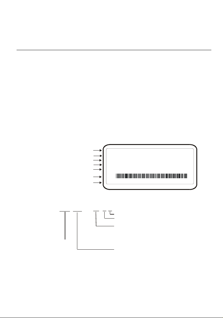
1.1.1 Nameplate Information
Example for 10HP/7.5kW 3-phase 460V AC drive
AC Drive Model
Input Spec.
Output Frequency Range
Output Spec.
Enclosure type
Bar Code
Serial Number
MODE : VFD075F 43A-G
INPUT : 3PH 380-480V 50/60Hz 19.0 A
OUTPUT : 3PH 0-480V 18A 14kVA 10HP
Freq. Range : 0.1~120.00Hz
ENCLOSURE: TYPE 1
075F43AG4T5010001
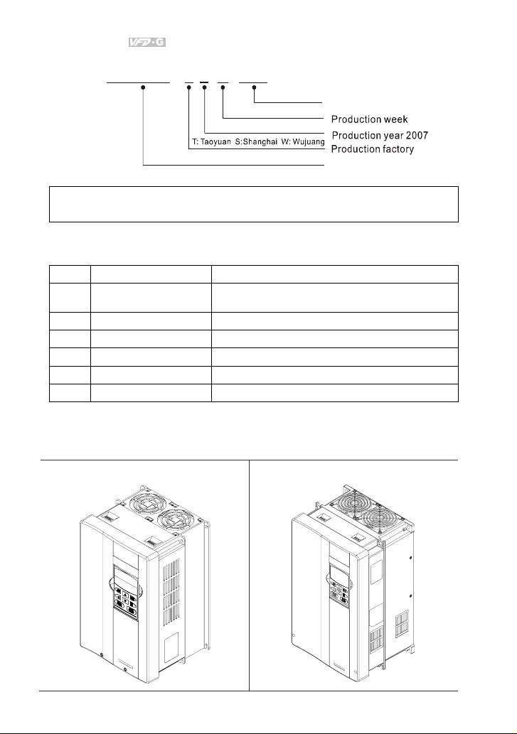
1.1.2 Model Explanation
AG-
VFD
07
Series
Name
Revision July 2008, EG03, SW V1.06 1-1
43
F
VFD-G series
Ver sion Typ e
Input Vol tage
43:Three phase 460V
055:7.5H P(5.5kW) 075:10HP (7.5kW) 110:15HP (11kW)
150:20HP (15kW) 185:25HP (18.5kW) 220:30HP (22kW)
300:40HP (30kW) 370:50HP( 37kW) 450:60H P(45kW)
550:75HP (55kW) 750:100HP (75kW) 900:125 HP(90kW)
1100:150HP(110kW) 1320:175HP(132kW) 1600:215HP(160kW)
1850:250 HP(185kW) 2200:300H P(220kW)
Applicable motor capacity
Page 11
Chapter 1 Introduction|
1.1.3 Series Number Explanation
075F43AG4 T 7 01 0001
Production number
460V 3-PHASE 10HP(7.5kW)
Production model
If the nameplate information does not correspond to your purchase order or if there are
any problems, please contact your distributor.
1.1.4 Drive Frames
Frame Power Range Models
C 7.5-20HP (5.5-15kW)
D 25-40HP (18.5-30kW) VFD185F43A-G, VFD220F43A-G, VFD300F43A-G
E 50-75HP (37-55kW) VFD370F43A-G,VFD450F43A-G,VFD550F43A-G
E1 100-125HP (75-90kW) VFD750F43A-G,VFD900F43C-G
G 150-215HP (110-160kW) VFD1100F43C-G,VFD1320F43A-G,VFD1600F43A-G
H 250-300HP (185-220kW) VFD1850F43A-G, VFD2200F43A-G
1.2 Appearances
(Refer to chapter 2.3 for exact dimensions)
7.5-20HP/5.5-15kW(Frame C)
VFD055F43B-G, VFD075F43B-G, VFD110F43A-G,
VFD150F43A-G
25-40HP/18.5-30kW(Frame D)
1-2 Revision July 2008, EG03, SW V1.06
Page 12
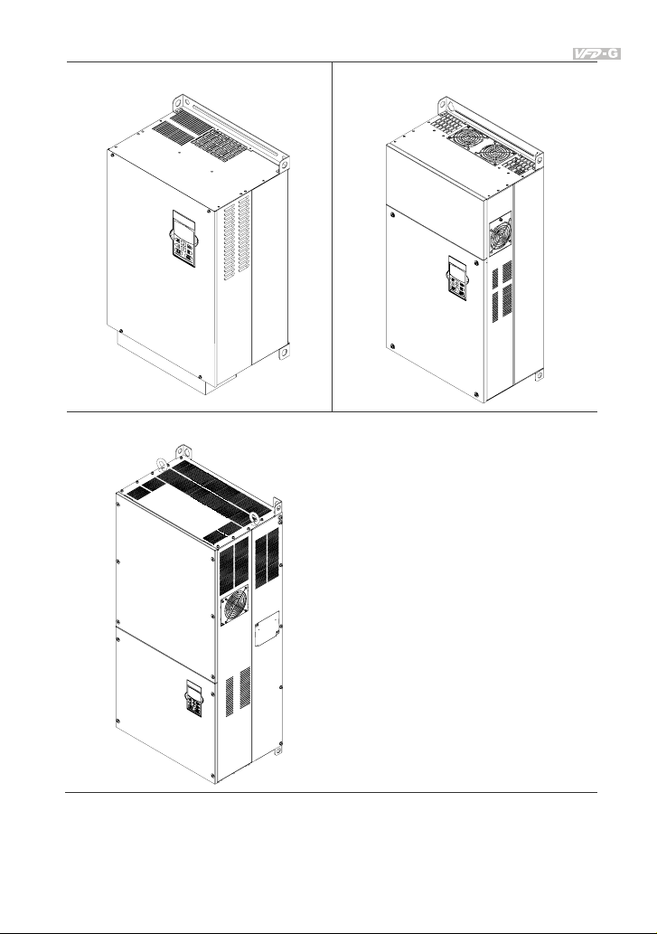
50-125HP/37-90kW(Frame E, E1)
Chapter 1 Introduction|
150-215HP/110-160kW(Frame G)
250-300HP/185-220kW(Frame H)
Revision July 2008, EG03, SW V1.06 1-3
Page 13
Chapter 1 Introduction|
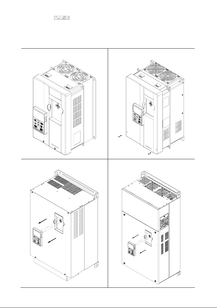
1.3 Remove Instructions
1.3.1 Remove Keypad
7.5-20HP/5.5-15kW(Frame C)
50-125HP/37-90kW(Frame E, E1)
25-40HP/18.5-30kW(Frame D)
150-215HP/110-160kW(Frame G)
1-4 Revision July 2008, EG03, SW V1.06
Page 14
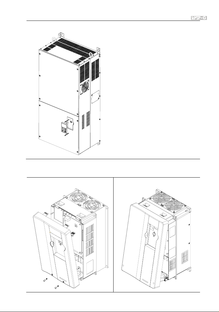
Chapter 1 Introduction|
250-300HP/185-220kW(Frame H)
1.3.2 Remove Front Cover
7.5-20HP/5.5-15kW(Frame C) 25-40HP/18.5-30kW(Frame D)
Revision July 2008, EG03, SW V1.06 1-5
Page 15
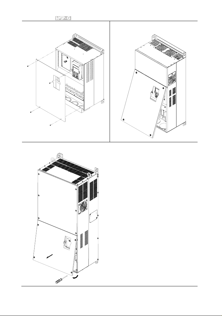
Chapter 1 Introduction|
50-125HP/37-90kW(Frame E, E1) 150-215HP/110-160kW(Frame G)
250-300HP/185-220kW(Frame H)
1-6 Revision July 2008, EG03, SW V1.06
Page 16
Chapter 1 Introduction|
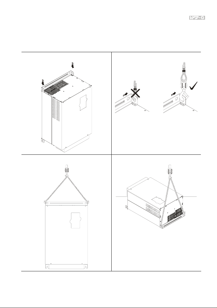
1.4 Lifting
Please carry only fully assembled AC motor drives as shown in the following.
For 50-125HP (Frame E, E1)
Step 1
Step 2
Step 3
Step 4
Revision July 2008, EG03, SW V1.06 1-7
Page 17
Chapter 1 Introduction|
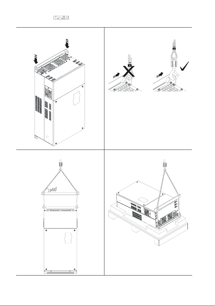
For 150-215HP (Frame G)
Step 1
Step 2
Step 3
Step 4
1-8 Revision July 2008, EG03, SW V1.06
Page 18
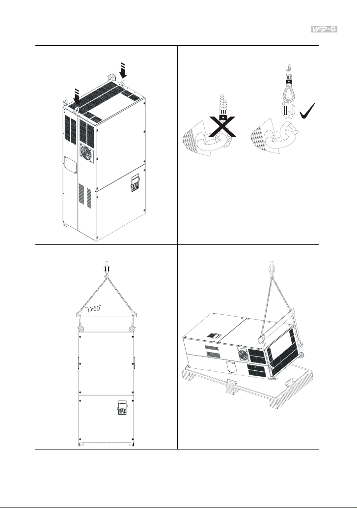
For 250-300HP (Frame H)
Step 1
Chapter 1 Introduction|
Step 2
Step 3
Step 4
Revision July 2008, EG03, SW V1.06 1-9
Page 19
Chapter 1 Introduction|
1.5 Preparation for Installation and Wiring
1.5.1 Ambient Conditions
Install the AC motor drive in an environment with the following conditions:
Air Temperature: -10 ~ +40°C (14 ~ 104°F)
Relative Humidity: <90%, no condensation allowed
Operation
Atmosphere
pressure:
Installation Site
Altitude:
Vibration:
86 ~ 106 kPa
<1000m
<20Hz: 9.80 m/s2 (1G) max
20 ~ 50Hz: 5.88 m/s2 (0.6G) max
Temperature: -20°C ~ +60°C (-4°F ~ 140°F)
Storage
Transportation
Relative Humidity: <90%, no condensation allowed
Atmosphere
pressure:
Vibration:
86 ~ 106 kPa
<20Hz: 9.80 m/s2 (1G) max
20 ~ 50Hz: 5.88 m/s2 (0.6G) max
Pollution Degree 2: good for a factory type environment.
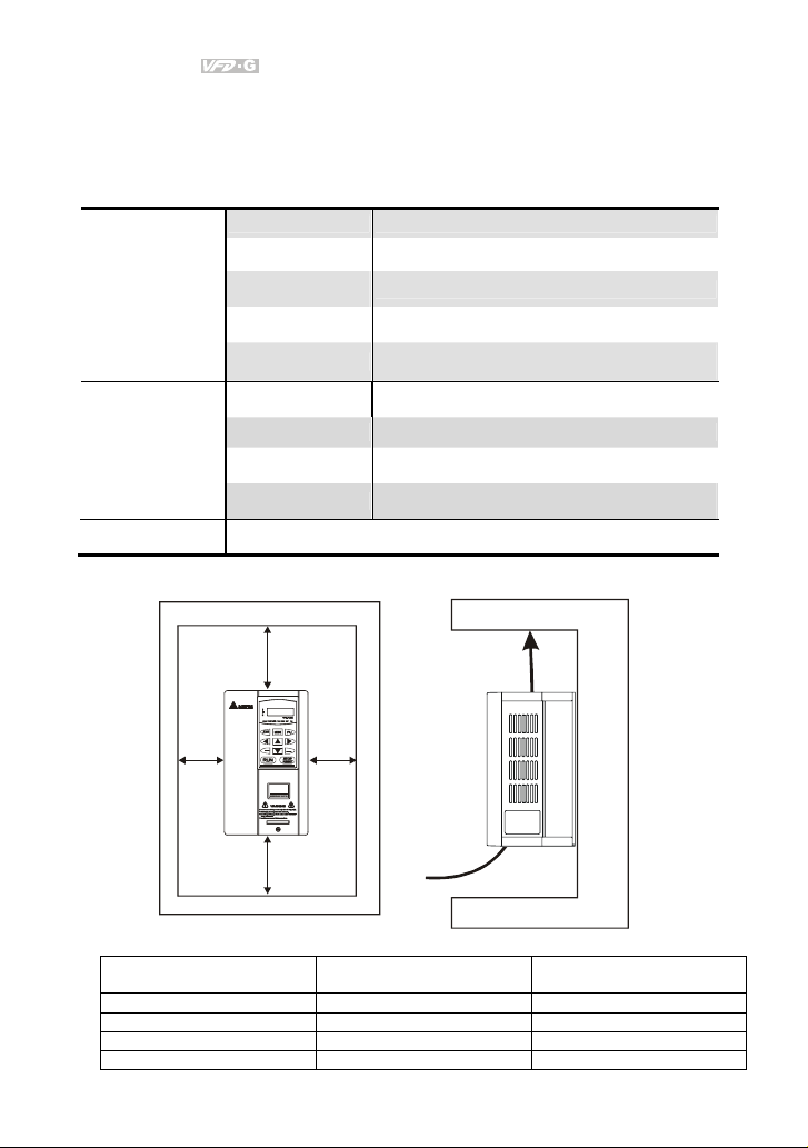
1.5.2 Minimum Mounting Clearances
H
FWD
PROG
REV
DATA
W
W
Air Flow
H
HP
W
mm (inch)
1-5HP 50 (2) 150 (6)
7.5-20HP 75 (3) 175 (7)
25-75HP 75 (3) 200 (8)
100HP and above 75 (3) 250 (10)
1-10 Revision July 2008, EG03, SW V1.06
H
mm (inch)
Page 20

Chapter 1 Introduction|
CAUTION!
1. Operating, storing or transporting the AC motor drive outside these conditions may cause
damage to the AC motor drive.
2. Failure to observe these precautions may void the warranty!
3. Mount the AC motor drive vertically on a flat vertical surface object by screws. Other directions
are not allowed.
4. The AC motor drive will generate heat during operation. Allow sufficient space around the unit
for heat dissipation.
5. The heat sink temperature may rise to 90°C when running. The material on which the AC motor
drive is mounted must be noncombustible and be able to withstand this high temperature.
6. When AC motor drive is installed in a confined space (e.g. cabinet), the surrounding
temperature must be within 10 ~ 40°C with good ventilation. DO NOT install the AC motor drive
in a space with bad ventilation.
7. Prevent fiber particles, scraps of paper, saw dust, metal particles, etc. from adhering to the
heatsink.
8. When installing multiple AC more drives in the same cabinet, they should be adjacent in a row
with enough space in-between. When installing one AC motor drive below another one, use a
metal separation between the AC motor drives to prevent mutual heating.
Revision July 2008, EG03, SW V1.06 1-11
Page 21
Chapter 1 Introduction|
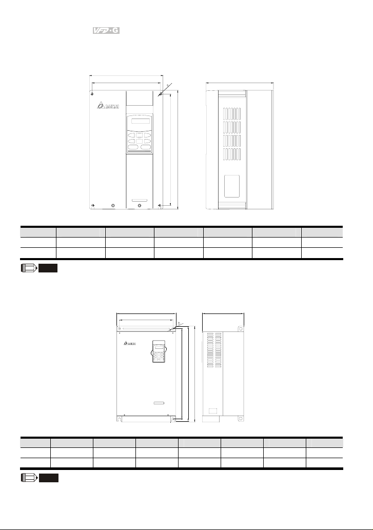
1.6 Dimensions
W
W1
F
H
H1
Frame W W1 H H1 D F
C 200.0 [7.88] 185.6 [7.31] 323.0 [12.72] 303.0 [11.93] 183.2 [7.22] 7.0 [0.28]
D 250.0 [9.84] 226.0 [8.90] 403.8 [15.90] 384.0 [15.12] 205.4 [8.08] 10.0 [0.39]
NOTE
Frame C: VFD055F43B-G, VFD075F43B-G, VFD110F43A-G, VFD150F43A-G
Frame D: VFD185F43A-G, VFD220F43A-G, VFD300F43A-G
W D
W1
F
D
Unit: mm [inch]
H
H1
H2
Unit: mm [inch]
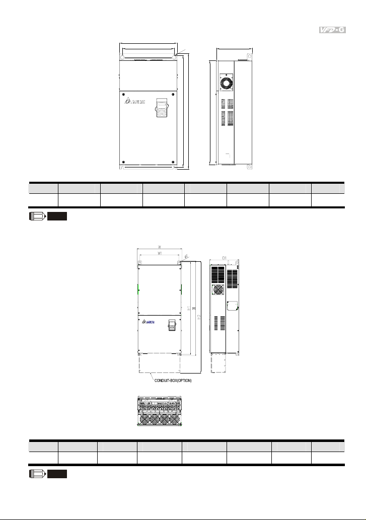
Frame W W1 H H1 H2 D F
E
370.0[14.57] 335.0[13.19] 589.0[23.19] 560.0[22.05] - 260.0[10.24] 13. 0[0.51]
E1
370.0[14.57] 335.0[13.19] 589.0[23.19] 560.0[22.05] 595.0[23.43] 260.0[10.24] 13.0[0.51]
NOTE
Frame E: VFD370F43A-G, VFD450F43A-G, VFD550F43A-G
Frame E1: VFD750F43A-G, VFD900F43C-G
1-12 Revision July 2008, EG03, SW V1.06
Page 22
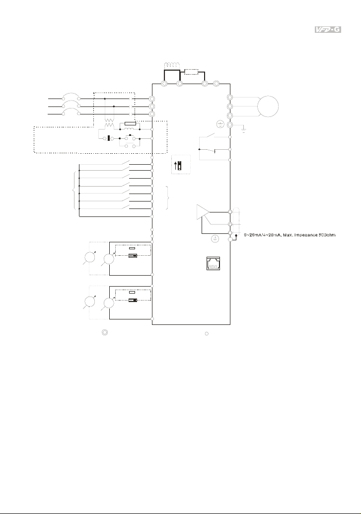
W
Chapter 1 Introduction|
W1
F
R
H
H1
D
H2
Unit: mm [inch]
Frame W W1 H H1 H2 D F
G
425.0[16.73] 381.0[15.00] 850.0[33.46] 819.5[32.26] 764.0[30.08] 264.0[10.39] 6.5[0.26]
NOTE
Frame G: VFD1100F43C-G, VFD1320F43A-G, VFD1600F43A-G
Unit: mm [inch]
Frame W W1 H H1 H2 D1 F
H
547.0[21.54] 480.0[18.90] 1150.0[4 5.28] 1119.0[4 4.06] 1357.6[53.45] 360.0[14.17] 13.0[0.51]
NOTE
Frame H: VFD1850F43A-G, VFD2200F43A-G
Revision July 2008, EG03, SW V1.06 1-13
Page 23

Chapter 1 Introduction|
This page intentionally left blank.
1-14 Revision July 2008, EG03, SW V1.06
Page 24

Chapter 2 Installation and Wiring
After removing the front cover, check if the power and control terminals are clear. Be sure to observe
the following precautions when wiring.
General Wiring Information
Applicable Codes
All VFD-G series are Underwriters Laboratories, Inc. (UL) and Canadian Underwriters
Laboratories (cUL) listed, and therefore comply with the requirements of the National Electrical
Code (NEC) and the Canadian Electrical Code (CEC).
Installation intended to meet the UL and cUL requirements must follow the instructions provided
in “Wiring Notes” as a minimum standard. Follow all local codes that exceed UL and cUL
requirements. Refer to the technical data label affixed to the AC motor drive and the motor
nameplate for electrical data.
The "Line Fuse Specification" in Appendix B, lists the recommended fuse part number for each
VFD-G Series part number. These fuses (or equivalent) must be used on all installations where
compliance with U.L. standards is a required.
CAUTION!
1. Make sure that power is only applied to the R/L1, S/L2, T/L3 terminals. Failure to comply may
result in damage to the equipment. The voltage and current should lie within the range as
indicated on the nameplate.
2. All the units must be grounded directly to a common ground terminal to prevent lightning strike
or electric shock.
3. Please make sure to fasten the screw of the main circuit terminals to prevent sparks which is
made by the loose screws due to vibration.
4. Check following items after finishing the wiring:
A. Are all connections correct?
B. No loose wires?
C. No short-circuits between terminals or to ground?
Revision July 2008, EG03, SW V1.06 2-1
Page 25

Chapter 2 Installation and Wiring|
DANGER!
1. A charge may still remain in the DC bus capacitors with hazardous voltages even if the power
has been turned off. To prevent personal injury, please ensure that the power is turned off and
wait ten minutes for the capacitors to discharge to safe voltage levels before opening the AC
motor drive.
2. Only qualified personnel familiar with AC motor drives is allowed to perform installation, wiring
and commissioning.
3. Make sure that the power is off before doing any wiring to prevent electric shock.
2.1 Wiring
Users must connect wires according to the circuit diagrams on the following pages. Do not plug a
modem or telephone line to the RS-485 communication port or permanent damage may result. Pins 1
& 2 are the power supply for the optional copy keypad only and should not be used for RS-485
communication.
2-2 Revision July 2008, EG03, SW V1.06
Page 26
For 460V series, 20hp and below
R/L1
NFB
S/L2
T/L3
NFB
Recommended Circuit
when power supply
is turned OFF by a
fault output
E.F.
FWD/STOP
REV/STOP
Factory
Setting
Multi-s tep1
Multi-s tep2
Multi-s tep3
Multi-s tep4
Digital Signal Common
*Don't apply the mains voltage
directly to above terminals.
0~10V
0~10V
V
Analog Signal Common
V
Analog Signal Common
MC
SA
ON
OFF
0-10V
SW2
A
0~1A
0-10V
SW3
A
0~1A
Main c ircuit (po wer) term inals
DC Reactor
(Optional)
Jumper
MC
0-1A
0-1A
R/L1
S/L2
T/L3
RB1
RC1
+24V
EF
FWD
REV
MI1
MI2
MI3
MI4
DCM
+12V
ACM
AI1
AC1
AI2
AC2
+1
Brak e Resistor
(Optional)
BR
+2/B1
VFD-G
Sink
Sw1
Source
Multi-fu nction
input
terminals
Chapter 2 Installation and Wiring|
-
B2
U/T1
V/T2
W/T3
RA1
240VAC 2.5A
RB1
120VAC 5A
28VDC 5A
RC1
AFM1
AFM2
AOM
E
61←
NOTE:*1-3 are optional.
Control circuit terminals
Motor
IM
3~
Mu lti-fu nction in dicati on
out put c onta cts
Factory setting: disable
Multi-function Analog
output terminal
Factory setting: output frequency
0~10VDC/2mA
Factory setting: output current
Analog Signal Common
RS-485
Serial communication interface
1: Reserved
2: GND
3: SG4: SG+
5:
Reserved
6:
Reserved
Revision July 2008, EG03, SW V1.06 2-3
Page 27
Chapter 2 Installation and Wiring|
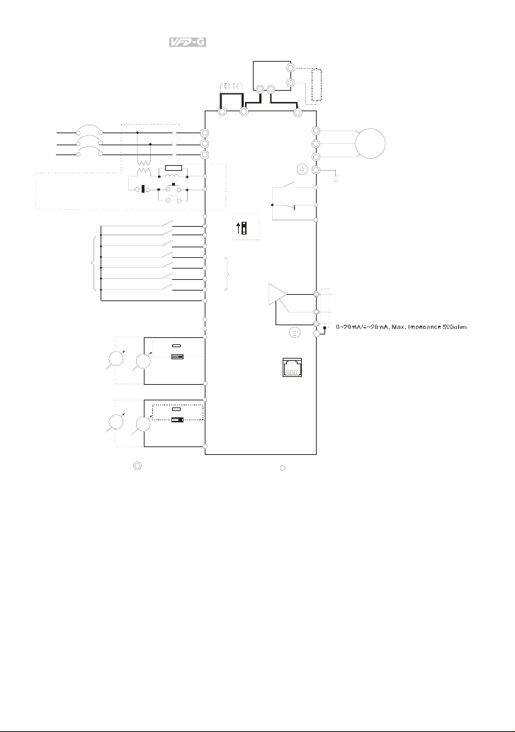
For 460V series, 25hp and above
Jumper
R/L1
NFB
S/L2
T/L3
NFB
Recommended Circuit
when power supply
is turned OFF by a
fault output
E.F.
FWD/STOP
REV/STOP
Factory
Setting
Multi-s tep1
Multi-s tep2
Multi-s tep3
Multi-s tep4
Digital Signal Common
*Don't apply the mains voltage
directly to above terminals.
0~10V
V
OFF
A
0-10V
0~1A
MC
SA
ON
MC
0-1A
SW2
Analog Signal Common
0-10V
0-1A
A
SW3
0~1A
V
0~10V
Analog Signal Common
Main c ircuit (po wer) term inals
DC Reactor
(Op tional )
+1 +2
R/L1
S/L2
T/L3
RB1
RC1
+24V
EF
FWD
REV
MI1
MI2
Multi-fu nction
input
MI3
terminals
MI4
DCM
+12V
ACM
AI1
AC1
AI2
AC2
VFDB
PN
VFD-G
Sink
Sw1
Source
Brake
Unit (Opt ional)
B1
B2
U/T1
Brake
Resist or
(Optional)
-
V/T2
W/T3
RA1
Mu lti-fu nction in dicati on
out put c onta cts
240VAC 2.5A
RB1
120VAC 5A
28VDC 5A
RC1
Factory setting: disable
Multi-function Analog
output terminal
Factory setting: output frequency
0~10VDC/2mA
Factory setting: output current
AOM
E
Analog Signal Common
RS-485
Serial communication interface
1: Reserved
2: GND
3: SG4: SG+
5:
Reserved
6:
Reserved
61←
AFM1
AFM2
NOTE:*1-3 are optional.
Control circuit terminals
Motor
IM
3~
2-4 Revision July 2008, EG03, SW V1.06
Page 28
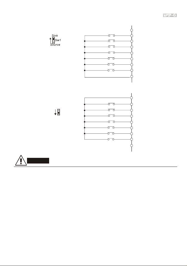
Wiring for SINK mode and SOURCE mode
Chapter 2 Installation and Wiring|
SINK Mode
*Don't apply the mains voltage direct ly
to above terminals
SOURCE Mode
Sink
Sw1
Source
*Don't apply the mains voltage directly
to above terminals
CAUTION!
1. The wiring of main circuit and control circuit should be separated to prevent erroneous actions.
2. Please use shield wire for the control wiring and not to expose the peeled-off net in front of the
terminal.
3. Please use the shield wire or tube for the power wiring and ground the two ends of the shield
wire or tube.
4. Damaged insulation of wiring may cause personal injury or damage to circuits/equipment if it
comes in contact with high voltage.
5. The AC motor drive, motor and wiring may cause interference. To prevent the equipment
damage, please take care of the erroneous actions of the surrounding sensors and the
equipment.
6. When the AC drive output terminals U/T1, V/T2, and W/T3 are connected to the motor terminals
U/T1, V/T2, and W/T3, respectively. To permanently reverse the direction of motor rotation,
switch over any of the two motor leads.
E.F.
FWD/STOP
REV/STOP
Multi-st ep1
Multi-step2
Multi-st ep3
Multi-step4
Digital Signal Common
E.F.
FWD/STOP
REV/STOP
Multi-step1
Multi-step2
Multi-step3
Multi-step4
+24V
EF
FWD
REV
MI1
MI2
MI3
MI4
DCM
+24V
EF
FWD
REV
MI1
MI2
MI3
MI4
DCM
Revision July 2008, EG03, SW V1.06 2-5
Page 29
Chapter 2 Installation and Wiring|
7. With long motor cables, high capacitive switching current peaks can cause over-current, high
leakage current or lower current readout accuracy. To prevent this, the motor cable should be
less than 20m for 3.7kW models and below. And the cable should be less than 50m for 5.5kW
models and above. For longer motor cables use an AC output reactor.
8. The AC motor drive, electric welding machine and the greater horsepower motor should be
grounded separately.
9. Use ground leads that comply with local regulations and keep them as short as possible.
10. No brake resistor is built in the VFD-G series, it can install brake resistor for those occasions
that use higher load inertia or frequent start/stop. Refer to Appendix B for details.
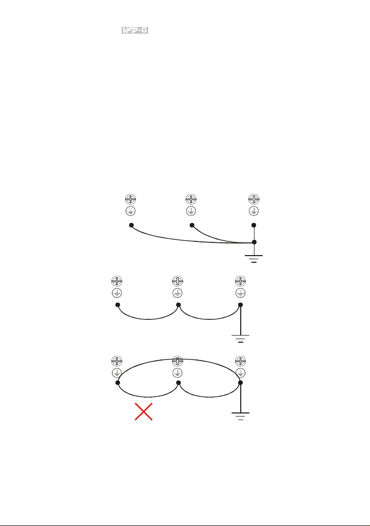
11. Multiple VFD-G units can be installed in one location. All the units should be grounded directly
to a common ground terminal, as shown in the figure below. Ensure there are no ground
loops.
Excellent
Good
Not allowed
2-6 Revision July 2008, EG03, SW V1.06
Page 30
Chapter 2 Installation and Wiring|
y
≤
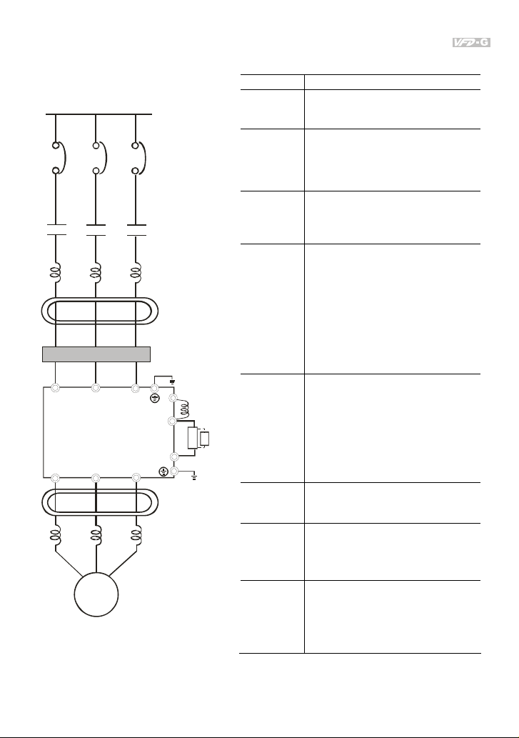
2.2 External Wiring
Power Suppl
EMI Filter
R/L1 S/L2
U/T1
V/T2
Motor
T/L3
W/T3
FUSE/NFB
Magnet ic
contact or
Input AC
Line React or
Zero-phase
Reactor
+1
+2
-
Zero-phase
Reactor
Outpu t AC
Line React or
DC
Choke
VFDB
Brak e
BR
Brak e
unit
Items Explanations
Power
supply
Please follow the specific power
supply requirements shown in
Appendix A.
There may be an inrush current during
Fuse/NFB
(Optional)
power up. Please check the chart of
Appendix B and select the correct fuse
with rated current. Use of an NFB is
optional.
Magnetic
contactor
(Optional)
Please do not use a Magnetic
contactor as the I/O switch of the AC
motor drive, as it will reduce the
operating life cycle of the AC drive.
Used to improve the input power
factor, to reduce harmonics and
provide protection from AC line
disturbances (surges, switching
Input AC
Line Reactor
(Optional)
spikes, short interruptions, etc.). AC
line reactor should be installed when
the power supply capacity is ≧500kVA
or phase lead reactor will be switched.
And the mains wiring distance
Please refer to Appendix B for more
details.
Zero phase reactors are used to
Zero-phase
Reactor
(Ferrite Core
Common
resistor
Choke)
(Optional)
reduce radio noise especially when
audio equipment is installed near the
inverter. Effective for noise reduction
on both the input and output sides.
Attenuation quality is good for a wide
range from AM band to 10MHz.
Appendix B specifies the zero phase
reactor. (RF220X00A)
EMI filter
(Optional)
Brake
Resistor
(Optional)
To reduce electromagnetic
interference, please refer to Appendix
B for more details.
Used to reduce the deceleration time
of the motor. Please refer to the chart
in Appendix B for specific Brake
Resistors.
Motor surge voltage amplitude
Output AC
Line Reactor
(Optional)
depends on motor cable length. For
applications with long motor cable
(>20m), it is necessary to install a
reactor at the inverter output side.
10m.
Revision July 2008, EG03, SW V1.06 2-7
Page 31

Chapter 2 Installation and Wiring|
e
2.3 Main Circuit Connection
For 460V series , 20hp and below
DC Reactor
(Optional)
Jumper
Brake Resistor
(Optional)
BR
R/L1
S/L2
T/L3
NFB
NFB
+1
MC
R/L1
S/L2
T/L3
+2/B1
VFD-G
B2
-
U/T1
V/T2
W/T3
For 460V series , 25hp and above
DC Reactor
(Op tiona l)
Jumper
R/L1
S/L2
T/L3
NFB
NFB
MC
+1 +2
R/L1
S/L2
T/L3
VFD-G
Terminal Symbol Explanation of Terminal Function
R/L1, S/L2, T/L3 AC line input terminals
U/T1, V/T2, W/T3 AC drive output terminals motor connections
+1, +2 Connections for DC Link Reactor (optional)
+2/B1~B2 Connections for Braking Resistor (optional)
+2~ -, +2/B1~ - Connections for External Braking Unit (VFDB series)
Earth Ground
VFDB
PN
Brak
Unit (Op tional)
B1
B2
-
U/T1
V/T2
W/T3
Brake
Resistor
(Optional)
Motor
IM
3~
Motor
IM
3~
2-8 Revision July 2008, EG03, SW V1.06
Page 32

Chapter 2 Installation and Wiring|
CAUTION!
Mains power terminals (R/L1, S/L2, T/L3)
Connect these terminals (R/L1, S/L2, T/L3) via a non-fuse breaker or earth leakage breaker to 3-
phase AC power (some models to 1-phase AC power) for circuit protection. It is unnecessary to
consider phase-sequence.
It is recommended to add a magnetic contactor (MC) in the power input wiring to cut off power
quickly and reduce malfunction when activating the protection function of AC motor drives. Both
ends of the MC should have an R-C surge absorber.
Please make sure to fasten the screw of the main circuit terminals to prevent sparks which is
made by the loose screws due to vibration.
Please use voltage and current within the regulation shown in Appendix A.
When using a general GFCI (Ground Fault Circuit Interrupter), select a current sensor with
sensitivity of 200mA or above, and not less than 0.1-second detection time to avoid nuisance
tripping. For the specific GFCI of the AC motor drive, please select a current sensor with
sensitivity of 30mA or above.
Do NOT run/stop AC motor drives by turning the power ON/OFF. Run/stop AC motor drives by
RUN/STOP command via control terminals or keypad. If you still need to run/stop AC drives by
turning power ON/OFF, it is recommended to do so only ONCE per hour.
Do NOT connect 3-phase models to a 1-phase power source.
Output terminals for main circuit (U, V, W)
When it needs to install the filter at the output side of terminals U/T1, V/T2, W/T3 on the AC
motor drive. Please use inductance filter. Do not use phase-compensation capacitors or L-C
(Inductance-Capacitance) or R-C (Resistance-Capacitance), unless approved by Delta.
DO NOT connect phase-compensation capacitors or surge absorbers at the output terminals of
AC motor drives.
Use well-insulated motor, suitable for inverter operation.
Terminals [+1, +2(+2/B1)] for connecting DC reactor
DC Reactor
DC Reactor
Jumper
+1
For 460V series, 20HP and below
Revision July 2008, EG03, SW V1.06 2-9
Jumper
+1
For 460V series, 25HP and above
Page 33

Chapter 2 Installation and Wiring|
)
)
To improve the power factor and reduce harmonics, connect a DC reactor between terminals [+1,
+2(+2/B1)]. Please remove the jumper before connecting the DC reactor.
Models of 18.5kW~160kW have a built-in DC reactor; models of 185kW~220kW have a built-in
AC reactor.
Terminals [+2/B1, B2] for connecting brake resistor and terminals [+2(+2/B1), -] for connecting
external brake unit
Brake Resis tor (Optional
Refer to Appen dix B for detail s.
BR
+2/B1
For 460V series , 20HP and below
Connect a brake resistor or brake unit in applications with frequent deceleration ramps, short
deceleration time, too low brake torque or requiring increased brake torque.
If the AC motor drive has a built-in brake chopper (all models of 15kW and below), connect the
external brake resistor to the terminals [+2/B1, B2].
Models of 18.5kW and above don’t have a built-in brake chopper. Please connect an external
optional brake unit (VFDB-series) and brake resistor. Refer to VFDB series user manual for
details.
When not used, please leave the terminals [+2(+2/B1), -] open.
Short-circuiting [B2] or [-] to [+2/B1] can damage the AC motor drive.
Connect the terminals [+(P), -(N)] of the brake unit to the AC motor drive terminals
[+2(+2/B1), -]. The length of wiring should be less than 5m with twisted cable.
B2
+2
For 460V series , 25HP and above
Brake Resis tor/Unit ( Optional
BR
Refer to App endix B f or details.
VFDB
-
2-10 Revision July 2008, EG03, SW V1.06
Page 34

2.4 Control Terminals
Chapter 2 Installation and Wiring|
Terminal
Terminal Function Factory Settings
Symbol
FWD-DCM:
FWD Forward-Stop command
ON: Run in FWD direction
OFF: Ramp to stop
REV-DCM:
REV Reverse-Stop command
ON: Run in REV direction
OFF: Ramp to stop
EF-DCM:
EF External fault
ON: External Fault. Display “EF” and coast/ramp to stop
OFF: No fault
MI1 Multi-function Input 1
MI2 Multi-function Input 2
MI3 Multi-function Input 3
MI4 Multi-function Input 4
+24V DC Voltage Source
DCM Digital Signal Common
MI1~MI4-DCM:
Refer to Pr.04-00~Pr.04-03 for programming multi-
function inputs.
ON: the activation current is 16mA.
OFF: leakage current tolerance is 10μA.
+24V 20mA
used for Source mode.
Used as common for digital inputs and used for Sink
mode.
0 to 10V, 2mA
Impedance: 470Ω
AFM1 Analog output meter 1
Output current: 2mA m ax
Resolution: 8 bits
Range: 0 ~ 10VDC
Function: Pr.03-05
Load Impedance: ≦500Ω
Output current: 20mA ma x
AFM2 Analog output meter 2
Resolution: 8 bits
Range: 0/4 ~ 20mA
Function: Pr.03-06
AOM Analog control signal common Used as common for analog outputs.
Multi-function Relay1 output
RA1
(N.O.) a
Multi-function Relay1 output
RB1
(N.C.) b
Multi-function Relay1
RC1
common
Resistive Load:
5A(N.O.)/3A(N.C.) 240VAC
5A(N.O.)/3A(N.C.) 24VDC
Inductive Load:
1.5A(N.O.)/0.5A(N.C.) 240VAC
1.5A(N.O.)/0.5A(N.C.) 24VDC
Refer to Pr.03-00 for programming.
Revision July 2008, EG03, SW V1.06 2-11
Page 35

Chapter 2 Installation and Wiring|
Terminal
Symbol
+12V/ACM Potentiometer power source +12Vdc 20mA (Variable Resistor: 3~5KΩ)
AI1 Analog voltage/current Input
AI2 Analog voltage/current Input
AC1/AC2 Analog control signal common Used as common for analog inputs.
Analog inputs (AI1, AI2, AC1, AC2)
Analog input signals are easily affected by external noise. Use shielded wiring and keep it as
short as possible (<20m) with proper grounding. If the noise is inductive, connecting the shield to
terminal AC1/AC2 can bring improvement.
If the analog input signals are affected by noise from the AC motor drive, please connect a
capacitor (0.1μF and above) and ferrite core as indicated in the following diagrams:
Terminal Function Factory Settings
0~10V/0~1A correspond to 0~Max. operation frequency
Resolution: 10 bits
Function: Pr.04-05 ~ Pr.04-25
0~10V/0~1A correspond to 0~Max. operation frequency
Resolution: 10 bits
Funciton: Pr.04-05 ~ Pr.04-25
NOTE: Control signal wiring size: 18 AWG (0.75 mm2) with shielded wire.
C
ferrite core
wind each wires 3 times or more around the core
Digital inputs (MI1~MI4, DCM, FWD, REV, EF)
When using contacts or switches to control the digital inputs, please use high quality
components to avoid contact bounce.
Relay outputs (RA1, RB1, RC1)
Make sure to connect the digital outputs to the right polarity, see wiring diagrams.
When connecting a relay to the digital outputs, connect a surge absorber or fly-back diode
across the coil and check the polarity.
2-12 Revision July 2008, EG03, SW V1.06
AI1/AI2
AC1/AC2
Page 36

Chapter 2 Installation and Wiring|
General
Keep control wiring as far away as possible from the power wiring and in separate conduits to
avoid interference. If necessary let them cross only at 90º angle.
The AC motor drive control wiring should be properly installed and not touch any live power
wiring or terminals.
NOTE
If a filter is required for reducing EMI (Electro Magnetic Interference), install it as close as
possible to AC drive. EMI can also be reduced by lowering the Carrier Frequency.
DANGER!
Damaged insulation of wiring may cause personal injury or damage to circuits/equipment if it comes
in contact with high voltage.
Revision July 2008, EG03, SW V1.06 2-13
Page 37

Chapter 2 Installation and Wiring|
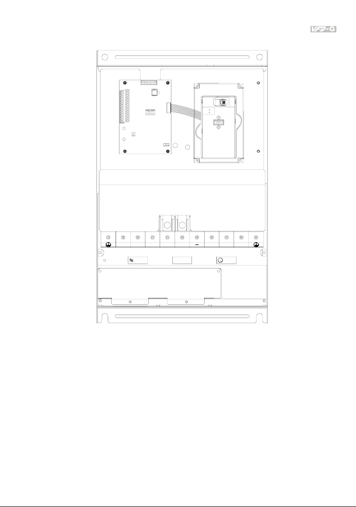
2.5 Specification for main circuit terminals and control terminals
7.5 HP to 20 HP (VFD055F43B-G, VFD075F43B-G, VFD110F43A-G, VFD150F43A-G)
POWER
IM
MOTOR3
Control Terminal
Torque: 4Kgf-cm (3 in-lbf)
Wire: 12-24 AWG
Power Terminal
Torque: 30Kgf-cm (26 in-lbf)
Wire: 12-8 AWG
Wire Type: Stranded copper only, 75° C
NOTE: If wiring of the terminal utilizes the wire with a 6AWG-diameter, it is thus necessary to
use the Recognized Ring Terminal to conduct a proper wiring.
2-14 Revision July 2008, EG03, SW V1.06
Page 38

Chapter 2 Installation and Wiring|
25 HP to 40 HP (VFD185F43A-G, VFD220F43A-G, VFD300F43A-G)
R/L1
S/L2
POWER
T/L3
+1
+2
( )
+ DC DC
-
( )
-
IM
3
MOTOR
W/T3V/T2
Control Terminal
Torque: 4Kgf-cm (3 in-lbf)
Wire: 12-24 AWG
Power Terminal
Torque: 30Kgf-cm (26 in-lbf)
Wire: 8-2 AWG
Wire Type: Stranded copper only, 75° C
NOTE: If wiring of the terminal utilizes the wire with a 1AWG-diameter, it is thus necessary to
use the Recognized Ring Terminal to conduct a proper wiring.
Revision July 2008, EG03, SW V1.06 2-15
Page 39

Chapter 2 Installation and Wiring|
50 HP to 60 HP (VFD370F43A-G, VFD450F43A-G)
R/L1
S/L2 T/L3 U/T1 V/T2 2/T3
CHARGE
+1
+2
POWER
ALARM
-
POWER
IM
MOTOR
3
Control Terminal
Torque: 4Kgf-cm (3 in-lbf)
Wire: 12-24 AWG
Power Terminal
Torque: 57kgf-cm (49.5 in-lbf) min.
Wire: VFD370F43A-G: 3AWG
VFD450F43A-G: 2AWG
Wire Type: Stranded copper only, 75° C
2-16 Revision July 2008, EG03, SW V1.06
Page 40
Chapter 2 Installation and Wiring|
75 HP to 125 HP (VFD550F43A-G, VFD750F43A-G, VFD900F43C-G)
POWER
ALARM
CHARGE
W/T3S/L2R/L1 T/L3 +2+1 U/T1 V/T2
POWER
Screw Torque:
200kgf-cm
(173in-lbf)
IM
MOTOR
3
Control Terminal
Torque: 4Kgf-cm (3 in-lbf)
Wire: 12-24 AWG
Power Terminal
Torque: 200kgf-cm (173 in-lbf)
Wire: VFD550F43A-G: 1/0-4/0 AWG
VFD750F43A-G: 3/0-4/0 AWG
VFD900F43C-G: 4/0 AWG
Wire Type: Stranded copper only, 75°C
Revision July 2008, EG03, SW V1.06 2-17
Page 41

Chapter 2 Installation and Wiring|
150 HP to 215 HP (VFD1100F43C-G, VFD1320F43A-G, VFD1600F43A-G)
V/T2S/L2R/L1 +2T/L3 +1 U/T1 W/T3
POWER
DC(+)
DC(-)
3
IM
MOTOR
Control Terminal
Torque: 4Kgf-cm (3 in-lbf)
Wire: 12-24 AWG
NOTE: It needs following additional terminal when
wiring. The additional terminal dimension should
comply with the following figure.
Power Terminal
Torque: 300kgf-cm (260 in-lbf)
Wire: 1/0 AWG*2-300 MCM*2
Wire Type: Stranded copper only, 75°C
UNIT:mm
2-18 Revision July 2008, EG03, SW V1.06
Page 42

250 HP to 300 HP (VFD1850F43A-G, VFD2200F43A-G)
+
( )
POWER
DC + DC
Control Terminal
Torque: 4Kgf-cm (3 in-lbf)
Wire: 12-24 AWG
NOTE: It needs following additional terminal when
wiring, and add insulation sheath on position
where following figure shows.
Power Terminal
Torque: 408kgf-cm (354 in-lbf)
Wire: 500 MCM (max)
Wire Type: Stranded copper only, 75°C
Chapter 2 Installation and Wiring|
-
U/T1T/L3R/L1 S/L2
W/T3V/T2
( )-
Revision July 2008, EG03, SW V1.06 2-19
Page 43

Chapter 2 Installation and Wiring|
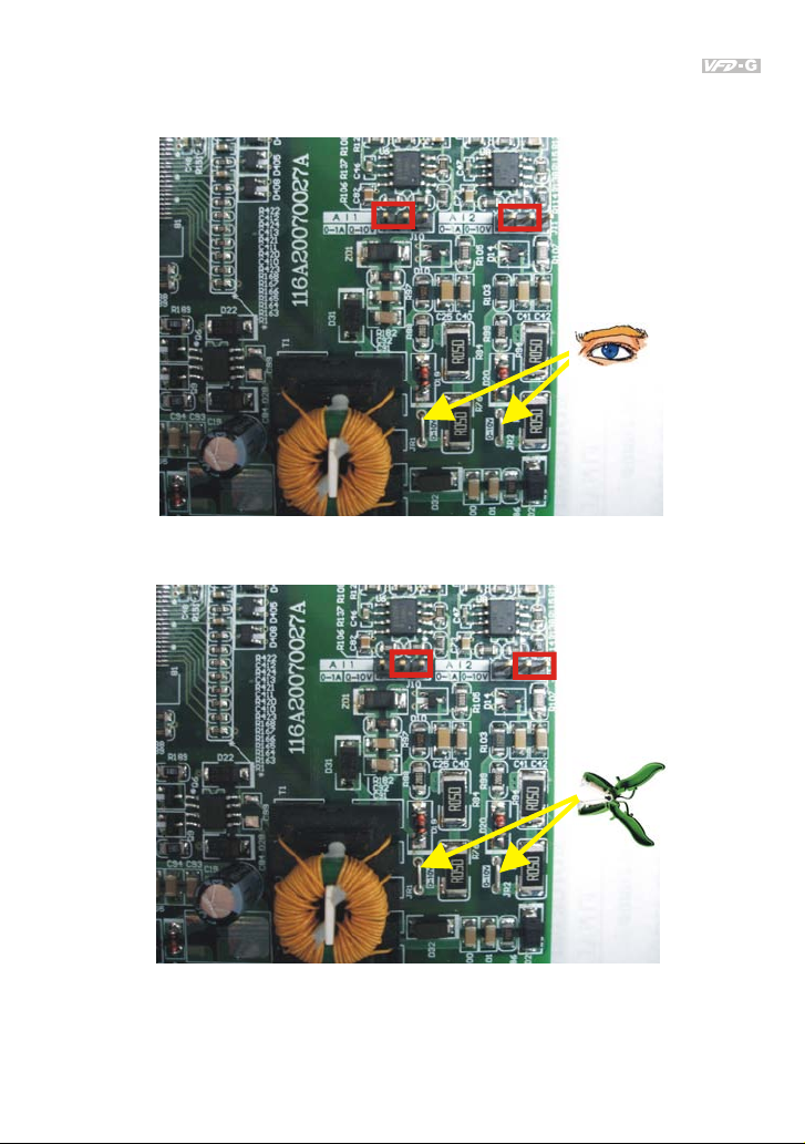
2.6 Wiring Explanation for Analog Input Terminal
When using analog input, please pay attention to the jumper on the control board. Whether the
jumper is cut off or not is determined by analog input type (voltage or current). See the figure below
and refer to the following explanation for more details.
2-20 Revision July 2008, EG03, SW V1.06
Page 44
Chapter 2 Installation and Wiring|
1. When using analog current input (0~1A), please plug into the left two pins (See the red mark),
and make sure the jumper is connected well (See what the following yellow arrows point at).
2. When using analog voltage input (0~10V), please transfer to the right two pins (See the red
mark), and cut off the jumper (See what the following yellow arrows point at).
Revision July 2008, EG03, SW V1.06 2-21
Page 45

Chapter 2 Installation and Wiring|
This page intentionally left blank.
2-22 Revision July 2008, EG03, SW V1.06
Page 46

Chapter 3 Keypad and Start Up
3.1 Digital Keypad VFD-PU01
3.1.1 Description of the Digital Keypad
JOG
By pressing JOG key.
Initiates jog operation.
moves cursor to the left
UP and DOWN Key
Sets the parameter
number and changes the
numerical data, such as
Master Frequency.
Left key
F
H
U
JOG
RUN
VFD-PU01
STOP
RESET
LED Display
Display frequency, cur rent , volt age
and error, etc.
Part Number
Status Display
Display the driver's current status
MODE
C
display mode.
STOP/RESET
RUN key
Display Message Descriptions
Display the AC drive Master Frequency.
Display the actual operation frequency present at terminals U/T1, V/T2,
and W/T3.
Display voltage (V), Current (A), power factor and feedback signal (P)
Display the output current present at terminals U/T1, V/T2, and W/T3.
Display the AC drive forward run status.
The AC drive reverse run status.
Display the specified parameter setting.
Display the actual value stored within the specified parameter.
External Fault.
hanges between different
Revision July 2008, EG03, SW V1.06 3-1
Page 47

Chapter 3 Keypad and Start Up|
Display Message Descriptions
Display “End” for approximately 1 second if input has been accepted.
After a parameter value has been set, the new value is automatically
stored in memory. To modify an entry, use the
Display “Err”, if the input is invalid.
3.1.2 How to Operate the Digital Keypad VFD-PU01
Selecting mode
START
F
H
U
F
H
U
MODE
In the selection mode, press
Note
:
Setting parameters
NOTE
:
To s h ift dat a
START
F
H
U
F
H
U
MODE
F
H
U
MODE
F
H
U
F
H
U
MODE
to set the parameters.
F
H
U
move to previous display
MODE
F
H
U
to return the selecting mode.In the parameter setting mode, you can press
or keys.
F
H
U
F
H
U
Success to set parameter.
F
H
U
Input data error
F
H
U
F
H
U
F
H
U
MODEMODE
GO START
To modify data
START
F
H
U
Setting direction
F
H
U
or
3-2 Revision July 2008, EG03, SW V1.06
F
H
U
F
H
U
F
H
U
F
H
U
or
Page 48

3.1.3 VFD-PU01 Dimensions
Chapter 3 Keypad and Start Up|
JOG
RUN
73.0 [2.87]
MODE
PROG
DATA
STOP
19.0 [0.75]
110.0 [4.33]
77.0 [3.03]
44.0 [1.73]
?
4
M4* 0.7(2X)
0
.
0
[
1
.
5
8
]
97.0 [3.82]
6.5 [0.26]
Unit: mm [inch]
3.1.4 Reference Table for the LED Display of the Digital Keypad
Digit 0 1 2 3 4 5 6 7 8 9
LED
Display
English
alphabet
LED
Display
English
alphabet
LED
Display
English
alphabet
LED
Display
A b Cc d E F G Hh Ii Jj
K L n Oo P q r S Tt U
v Y Z
Revision July 2008, EG03, SW V1.06 3-3
Page 49

Chapter 3 Keypad and Start Up|
3.2 Operation Method
The operation method can be set via communication, digital keypad and control terminals. Please
choose a suitable method depending on application and operation rule.
Operation Method Frequency Source Operation Command Source
Operate from the
communication
Refer to the communication address
2001H setting for details.
(Parameter setting: Pr.02-00=03)
F
H
U
Refer to the communication address
2000H setting for details.
(Parameter setting: Pr.02-01=03/04)
VFD-PU01
STOPRUN REV
FWDJOG
VFD-PU01 keypad
JOG
RUN
STOP
RESET
STOP
RESET
Multi-function
input
terminals
Operate from
external signal
E.F.
FWD/STOP
REV/STOP
Factory
default
Multi-step1
Multi-step2
Multi-step3
Multi-step4
Digital Signal Common
*Don 't a pply the mains voltage
directly to above terminals.
MI1-DCM (Set Pr.04-00=13)
MI2-DCM (Set Pr.04-01=14)
RUN
+24V
EF
FWD
REV
MI1
MI2
MI3
MI4
DCM
FWD-DCM (Set to FWD/STOP)
REV-DCM (Set to REV/STOP)
3-4 Revision July 2008, EG03, SW V1.06
Page 50

Chapter 3 Keypad and Start Up|
3.3 Trial Run
you can perform a trial run by using digital keypad with the following steps. The factory setting of the
operation source is from the keypad (Pr.02-01=00).
1. After applying power, verify that LED “F” is on and the display shows 60.00Hz.
2. Setting frequency to about 5Hz by using
3. Pressing
you should press
please press
4. Check following items:
RUN
key for forward running. And if you want to change to reverse running,
STOP
RESET
key in
key.
F
H
U
key.
page. And if you want to decelerate to stop,
Check if the motor direction of rotation is correct.
Check if the motor runs steadily without abnormal noise and vibration.
Check if acceleration and deceleration are smooth.
If the results of trial run are normal, please start the formal run.
NOTE
1. Stop running immediately if any fault occurs and refer to the troubleshooting guide for solving
the problem.
2. Do NOT touch output terminals U, V, W when power is still applied to L1/R, L2/S, L3/T even
when the AC motor drive has stopped. The DC-link capacitors may still be charged to
hazardous voltage levels, even if the power has been turned off.
3. To avoid damage to components, do not touch them or the circuit boards with metal objects or
your bare hands.
Revision July 2008, EG03, SW V1.06 3-5
Page 51

Chapter 3 Keypad and Start Up|
This page intentionally left blank.
3-6 Revision July 2008, EG03, SW V1.06
Page 52

Chapter 4 Parameters
The VFD-G parameters are divided into 10 groups by property for easy setting. In most applications,
the user can finish all parameter settings before start-up without the need for re-adjustment during
operation.
The 10 groups are as follows:
Group 0: User Parameters
Group 1: Basic Parameters
Group 2: Operation Method Parameters
Group 3: Output Function Parameters
Group 4: Input Function Parameters
Group 5: Multi-Step Speed Parameters
Group 6: Protection Function Parameters
Group 7: AC Drive and Motor Parameters
Group 8: Special Parameters
Group 9: Communication Parameters
Group 10: PID Control Parameters
Revision July 2008, EG03, SW V1.06 4-1
Page 53

Chapter 4 Parameters|
4.1 Summary of Parameter Settings
: The parameter can be set during operation.
Group 0 User Parameters
Parameter Functions Settings
00-00 Software Version Read only
00-01 AC Drive Status
Indication 1
00: No Fault occurred
01: oc (over current)
02: ov(over voltage)
03: oH(over temperature)
04: oL(overload)
05: oL1(electronic thermal relay)
06: EF(external Fault)
07: occ(AC drive IGBT fault)
08: CF3(CPU failure)
09: HPF(Hardware Protection Failure)
10: ocA(current exceed during Acceleration)
11: ocd(current exceed during Deceleration)
12: ocn(current exceed during Steady State)
13: GFF(Ground Fault)
14: Lv(Low voltage)
15: CF1(abnormal input data)
16: CF2(abnormal output data)
17: bb(Base Block)
18: oL2(over load2)
19: Reserved
20: codE(software or password protection)
21: EF1(external Emergency Stop)
22: PHL(phase loss)
23: Lc (Low Current)
24: FbL(Feedback Loss)
25: Reserved
26: FANP (Fan Power Fault)
27: FF1 (Fan 1 Fault)
28: FF2 (Fan 2 Fault)
29: FF3 (Fan 3 Fault)
30: FF123 (Fan 1, 2, 3 Fault)
31: FF12 (Fan 1, 2 Fault)
32: FF13 (Fan 1, 3 Fault)
33: FF23 (Fan 2, 3 Fault)
34: Fv (Gate Drive Low Voltage Protect)
35~40: Reserved
41: HPF1 (GFF hardware error)
42: HPF2 (CC,OC hardware error)
Factory
Setting
Read
Customer
4-2 Revision July 2008, EG03, SW V1.06
Page 54

Chapter 4 Parameters|
Parameter Functions Settings
43: HPF3 (OC hardware error)
Factory
Setting
44: HPF4 (OV hardware error)
45: CF3.3 (U-phase error)
46: CF3.4 (V-phase error)
47: CF3.5 (W-phase error)
48: CF3.6 (OV or LV)
49: CF3.7 (Isum error)
50: CF3.8 (Temperature sensor error)
00-02 AC Drive Status
Indication 2
Bit 0~1: 00: Run led is off and stop led is on.
01: Run led is blink and stop led is
Read
on.
10: Run led is on and stop led is
blink.
11: Run led is on and stop led is off.
Bit 2: 1: Jog on.
Bit 3~4: 00: Rev led is off and FWD led is on.
01: Rev led is blink and FWD led is
on.
10: Rev led is on and FWD led is
blink.
11: Rev led is on and FWD led is off.
Bit 5-7: Reserved
Bit 8: Master frequency source via
communication interface
Bit 9: Master frequency source via analog
Bit10: Running command via communication
interface
Bit11: Parameter locked
Bit12~15: Reserved
00-03 Frequency Setting (F)
Read only Read
or Closed Loop
Control Setting Point
00-04 Output Frequency (H) Read only Read
00-05 Output Current (A) Read only Read
00-06 DC-BUS Voltage (U) Read only Read
00-07 Output Voltage (E) Read only Read
00-08 Output Power Factor
Read only Read
(n)
00-09 Output Power (kW) Read only Read
00-10 Feedback Signal
Read only Read
Actual Value
00-11 Feedback Signal (%) Read only Read
00-12 User Target Value
Read only Read
(Low bit) uL 0-99.99
Customer
Revision July 2008, EG03, SW V1.06 4-3
Page 55

Chapter 4 Parameters|
Parameter Functions Settings
00-13 User Target Value
Read only Read
Factory
Setting
Customer
(High bit) uH 0-9999
00-14 PLC Time Read only Read
00-15 Output Reactive
Read only Read
Power (KVAR)
Group 1 Basic Parameters
Parameter Functions Settings
01-00 Maximum Output
50.00~160.00Hz 60.00
Factory
Setting
Customer
Frequency
01-01 Maximum Voltage
0.10~160.00 Hz 60.00
Frequency
(Base Frequency)
01-02 Maximum Output
0.2V ~ 510.0V 440.0
Voltage
01-03 Mid-point Frequency 0.10~120 Hz 3.00
01-04 Mid-point Voltage 0.2V~510.0V 11.0
01-05 Minimum Output
0.10~20.00 Hz 3.00
Frequency
01-06 Minimum Output
0.2V~100.0V 11.0
Voltage
01-07 Upper Bound
0.00~160.00 Hz 60.00
Frequency
01-08 Lower Bound
0.00~160.00 Hz 0.00
Frequency
01-09 Acceleration Time 1 0.1~3600.0 Sec 10.0/
60.0
01-10 Deceleration Time 1 0.1~3600.0 Sec 10.0/
60.0
01-11 Acceleration Time 2 0.1~3600.0 Sec 10.0/
60.0
01-12 Deceleration Time 2 0.1~3600.0 Sec 10.0/
60.0
01-13 Acceleration Time 3 0.1~3600.0 Sec 10.0/
60.0
01-14 Deceleration Time 3 0.1~3600.0 Sec 10.0/
60.0
01-15 Acceleration Time 4 0.1~3600.0 Sec 10.0/
60.0
01-16 Deceleration Time 4 0.1~3600.0 Sec 10.0/
60.0
4-4 Revision July 2008, EG03, SW V1.06
Page 56

Chapter 4 Parameters|
Parameter Functions Settings
01-17 JOG Acceleration
0.1~3600.0 Sec 10.0/
Time
01-18 JOG Deceleration
0.1~3600.0 Sec 10.0/
Time
Factory
Setting
60.0
60.0
Customer
01-19 JOG Frequency 0.0 Hz~160.00 Hz 6.00
01-20 S Curve Delay Time
0.00~2.50sec 0.00
in Accel
01-21 S Curve Delay Time
0.00~2.50sec 0.00
in Decel
01-22 Modulation Index 0.90~1.20 1.00
01-23 Accel/Decel Time Unit 00: Unit is 1 Sec
01
01: Unit is 0.1 Sec
02: Unit is 0.01 Sec
Group 2 Operation Method Parameters
Parameter Functions Settings
02-00 Source of Frequency
Command
00: via keypad
01: via analog input AI1
Factory
Customer
Setting
00
02: via analog input AI2
03: via RS485 serial communication
04: via External Reference
02-01 Source of Operation
Command
00: Controlled by the digital keypad
01: Controlled by the external terminals,
00
keypad STOP enabled.
02: Controlled by external terminals, keypad
STOP disabled.
03: Controlled by the RS-485 communication
interface, keypad STOP enabled.
04: Controlled by the RS-485 communication
interface, keypad STOP disabled.
02-02 Stop Method 00: Stop = ramp to stop, E.F. (External Fault)
00
= coast to stop
01: Stop = coast to stop, E.F. = coast to stop
02: Stop = ramp to stop, E.F. = ramp to stop
03: Stop = coast to stop, E.F. = ramp to stop
02-03 PWM Carrier
Frequency Selections
7.5~10HP: 4000~6000Hz
15~30HP: 3000~6000Hz
40~125HP: 2000~6000Hz
150~300HP: 2000~4000Hz
6000
6000
4000
4000
Revision July 2008, EG03, SW V1.06 4-5
Page 57

Chapter 4 Parameters|
Parameter Functions Settings
02-04 Forward/Reverse
Enable
00: Forward enabled
01: Reverse disabled
02: Forward disabled
02-05 2-wire/3-wire
Operation Control
Modes
00: 2-wire: FWD/STOP, REV/STOP
01: 2-wire: FWD/REV, RUN/STOP
02: 3-wire operation
02-06 Line Start Lockout 00: Disabled
01: Enabled
02-07 Reserved
02-08 Start-up Display
Selection
Bit0~1: 00 = F LED
01 = H LED
10 = U LED (special display)
11 = Fwd / Rev
Bit2: 0 = Fwd LED /
1 = Rev LED
Bit3~5: 000 = 1st 7-step
001 = 2nd 7-step
010 = 3rd 7-step
011 = 4th 7-step
100 = 5th 7-step
Bit6~7: Reserved
02-09 Special Display 00: A displays output current of AC drive
01: U displays DC-Bus voltage of AC drive
02: E displays RMS of output voltage
03: P displays feedback Signal
04: PLC display auto procedure state
02-10 User Defined
0.01~160.00
Coefficient
02-11 Flying Start 00: Disabled
01: Enable (Dc braking disabled)
02-12 Flying Start
Frequency
00: Trace from master frequency command
01: Trace from maximum setting frequency
01-00
02-13 Master Frequency
Memory Setting
00: Do not remember the last known
frequency
01: Remember the last known frequency
Factory
Customer
Setting
00
00
01
00
00
1.00
00
00
01
4-6 Revision July 2008, EG03, SW V1.06
Page 58

Chapter 4 Parameters|
Group 3 Output Function Parameters
Parameter Functions Settings
03-00 Multi-function Output
Terminal 1
(Relay)
00: disabled
01: Indication during operation
02: Master frequency attained
Factory
Customer
Setting
01
03: Zero Speed (including shutdown)
04: Over-torque
05: External Fault
06: Low voltage detection
07: Operation Mode indication
08: Fault indication
09: Master Frequency Attained 1
10: Master Frequency Attained 2
11: Over Temperature indication
12: Drive Ready
13: External Emergency Stop (EF1)
14: Software Braking Output
15: OL or OL1 Overload Warning
16: Low Current Indication
17: PID Feedback Error Indication
18: PLC Program Running
19: PLC Program Step Completed
20: PLC Program Completed
21: PLC Operation Paused
03-01 Reserved
03-02 Master Frequency
0.00~160.00 Hz 0.00
Attained 1
03-03 Master Frequency
0.00~160.00 Hz 0.00
Attained 2
03-04 DC Fan Control 00: Fan runs on power up.
00
01: Fan begins upon a RUN command. Fan
stops 1 minute after a STOP command.
02: Fan begins upon a RUN command. Fan
stops after a STOP command
03: Fan is controlled by temperature.
Fan will be started at approximate 60°C.
03-05 Analog Output Signal
1
03-06 Analog Output Signal
2
00: Output frequency
01: Output current
02: Output voltage
03: Frequency command
00
01
04: Power factor loading
03-07 Analog Output Gain 1 01~200% 100
03-08 Analog Output Gain 2 01~200% 100
03-09 Analog Output 2
Selection
Revision July 2008, EG03, SW V1.06 4-7
00: 0~20mA
01: 4~20mA
01
Page 59

Chapter 4 Parameters|
Group 4 Input Function Parameters
Parameter Functions Settings
04-00 Multi-function Input
Terminal 1
04-01 Multi-function Input
Terminal 2
04-02 Multi-function Input
Terminal 3
04-03 Multi-function Input
Terminal 4
00: disabled
01: Multi-Speed terminal 1
02: Multi-Speed terminal 2
03: Multi-Speed terminal 3
04: Multi-Speed terminal 4
05: Reset (NO)
06: Reset (NC)
07: Jog operation (JOG)
Factory
Customer
Setting
01
02
03
04
08: Accel/Decel disabled
09: 1st and 2nd Accel/Decel selection
10: 3rd and 4th Accel/Decel selection
11: B.B. (NO) input
12: B.B. (NC) input
13: Increase Frequency
14: Decrease Frequency
15: Emergency stop (NO)
16: Emergency stop (NC)
17: KEYPAD(open), EXT(close)
18: PID disable
19: Run PLC Program
20: Pause PLC Program
21: 1st Output Frequency Gain (Pr.04-30)
22: 2nd Output Frequency Gain (Pr.04-31)
23: 3rd Output Frequency Gain (Pr.04-32)
04-04 Digital Input Terminal
01~20 01
Response Time
04-05 Minimum AI1 Analog
0 ~ 100% 0
Input
04-06 Maximum AI1 Analog
0 ~ 100% 100
Input
04-07 Minimum Output that
0.00~100.00% 0.00
corresponds to AI1
04-08 Maximum Output that
0.00~100.00% 100.00
corresponds to AI1
04-09 Minimum AI2 Analog
0 ~ 100% 0
Input
04-10 Maximum AI2 Analog
0 ~ 100% 100
Input
04-11 Minimum Output that
0.0~100.0% 0.00
corresponds to AI2
04-12 Maximum Output that
0.0~100.0% 100.00
corresponds to AI2
04-13 1st AI1 Gain 0.0~100.0% 100.0
4-8 Revision July 2008, EG03, SW V1.06
Page 60

Chapter 4 Parameters|
Parameter Functions Settings
Factory
Setting
Customer
04-14 2nd AI1 Gain 0.0~100.0% 100.0
04-15 3rd AI1 Gain 0.0~100.0% 100.0
04-16 4th AI1 Gain 0.0~100.0% 100.0
04-17 5th AI1 Gain 0.0~100.0% 100.0
04-18 1st AI2 Gain 0.0~100.0% 100.0
04-19 2nd AI2 Gain 0.0~100.0% 100.0
04-20 3rd AI2 Gain 0.0~100.0% 100.0
04-21 4th AI2 Gain 0.0~100.0% 100.0
04-22 5th AI2 Gain 0.0~100.0% 100.0
04-23 Analog Input Delay
0.00~10.00 Sec 0.50
AI1
04-24 Analog Input Delay
0.00~10.00 Sec 0.50
AI2
04-25 Summation of
External Frequency
Sources
00: Disabled
01:AI1*( AI1 Gain) + AI2*( AI2 Gain)
02:AI1*( AI1 Gain) - AI2*( AI2 Gain)
00
03: AI1*( AI1 Gain) * AI2 *( AI2 Gain)
04: Reserved
05: Communication master
frequency+AI1*( AI1 Gain)
06: Communication master
frequency+AI2*( AI2 Gain)
07: Max (AI1*( AI1 Gain), AI2*( AI2 Gain))
04-26 1st AI Frequency
Gain
04-27 2nd AI Frequency
Gain
04-28 3rd AI Frequency
Gain
04-29 4th AI Frequency
Gain
04-30 1st Out Frequency
0.00: Disabled
0.00
0.01~160.00 Hz
0.00: Disabled
0.00
0.01~160.00 Hz
0.00: Disabled
0.00
0.01~160.00 Hz
0.00: Disabled
0.00
0.01~160.00 Hz
0.0 to 200.0% 100.0
Gain
04-31 2nd Out Frequency
0.0 to 200.0% 100.0
Gain
04-32 3rd Out Frequency
0.0 to 200.0% 100.0
Gain
Revision July 2008, EG03, SW V1.06 4-9
Page 61

Chapter 4 Parameters|
Group 5 Multi-step Speed Parameters
Parameter Functions Settings
05-00 1st Step Speed
0.00~160.00 Hz 0.00
Factory
Setting
Frequency
05-01 2nd Step Speed
0.00~160.00 Hz 0.00
Frequency
05-02 3rd Step Speed
0.00~160.00 Hz 0.00
Frequency
05-03 4th Step Speed
0.00~160.00 Hz 0.00
Frequency
05-04 5th Step Speed
0.00~160.00 Hz 0.00
Frequency
05-05 6th Step Speed
0.00~160.00 Hz 0.00
Frequency
05-06 7th Step Speed
0.00~160.00 Hz 0.00
Frequency
05-07 8th Step Speed
0.00~160.00 Hz 0.00
Frequency
05-08 9th Step Speed
0.00~160.00 Hz 0.00
Frequency
05-09 10th Step Speed
0.00~160.00 Hz 0.00
Frequency
05-10 11th Step Speed
0.00~160.00 Hz 0.00
Frequency
05-11 12th Step Speed
0.00~160.00 Hz 0.00
Frequency
05-12 13th Step Speed
0.00~160.00 Hz 0.00
Frequency
05-13 14th Step Speed
0.00~160.00 Hz 0.00
Frequency
05-14 15th Step Speed
0.00~160.00 Hz 0.00
Frequency
05-15 PLC Mode 00: Disable PLC Operation
00
01: Execute one program cycle
02: Continuously execute program cycles
03: Execute one program cycle step by step
04: Continuously execute program cycles
step by step
05-16 PLC Forward/ Reverse
Motion
00 to 32767 (00: FWD 01: REV) 00
05-17 Time Duration Step 1 0.0 to 65500 Sec / 0.0~6550.0 Sec 0.0
05-18 Time Duration Step 2 0.0 to 65500 Sec / 0.0~6550.0 Sec 0.0
05-19 Time Duration Step 3 0.0 to 65500 Sec / 0.0~6550.0 Sec 0.0
Customer
4-10 Revision July 2008, EG03, SW V1.06
Page 62

Chapter 4 Parameters|
Parameter Functions Settings
Factory
Setting
05-20 Time Duration Step 4 0.0 to 65500 Sec / 0.0~6550.0 Sec 0.0
05-21 Time Duration Step 5 0.0 to 65500 Sec / 0.0~6550.0 Sec 0.0
05-22 Time Duration Step 6 0.0 to 65500 Sec / 0.0~6550.0 Sec 0.0
05-23 Time Duration Step 7 0.0 to 65500 Sec / 0.0~6550.0 Sec 0.0
05-24 Time Duration Step 8 0.0 to 65500 Sec / 0.0~6550.0 Sec 0.0
05-25 Time Duration Step 9 0.0 to 65500 Sec / 0.0~6550.0 Sec 0.0
05-26 Time Duration Step 10 0.0 to 65500 Sec / 0.0~6550.0 Sec 0.0
05-27 Time Duration Step 11 0.0 to 65500 Sec / 0.0~6550.0 Sec 0.0
05-28 Time Duration Step 12 0.0 to 65500 Sec / 0.0~6550.0 Sec 0.0
05-29 Time Duration Step 13 0.0 to 65500 Sec / 0.0~6550.0 Sec 0.0
05-30 Time Duration Step 14 0.0 to 65500 Sec / 0.0~6550.0 Sec 0.0
05-31 Time Duration Step 15 0.0 to 65500 Sec / 0.0~6550.0 Sec 0.0
05-32 Time Unit Settings 00: 1 Sec
00
01: 0.1 Sec
Group 6 Protection Function Parameters
Parameter Functions Settings
06-00 Over-voltage Stall
Prevention
06-01 Over-current Stall
Prevention during
Acceleration
06-02 Over-current Stall
Prevention during
operation
06-03 Over-torque Detection
Selection
660.0V~820.0VDC
00: Disabled
20~250%
00: Disabled
20~250%
00: Disabled
00: Over-torque detection disabled.
01: Over-torque detection enabled during
Factory
Setting
780.0
150%
150%
00
constant speed operation (OL2), and
operation continues.
02: Over-torque detection enabled during
constant speed operation (OL2), and
operation halted.
03: Over-torque detection enabled during
operation (OL2), and operation
continues.
04: Over-torque detection enabled during
operation (OL2), and operation halted.
06-04 Over-torque Detection
30~150% 110
Level
06-05 Over-torque Detection
0.1~60.0 Sec 0.1
Time
Customer
Customer
Revision July 2008, EG03, SW V1.06 4-11
Page 63

Chapter 4 Parameters|
Parameter Functions Settings
06-06 Electronic Thermal
Relay Selection
00: Operate disabled.
01: Operate with a standard motor.
Factory
Setting
02
02: Operate with a special motor.
06-07 Electronic Thermal
30~600 Sec 60
Characteristic
06-08 Low Current Detection
00~100% (00 disabled) 00
Level
06-09 Low Current Detection
0.1~ 3600.0 Sec 10.0
Time
06-10 Low Current Detection
Treatment
00: Warn and Ramp to stop
01: Warn and Coast to stop
01
02: Warn and keep operating
06-11 Present Fault Record 00
06-12 Second Most Recent
Fault Record
06-13 Third Most Recent
Fault Record
06-14 Fourth Recent Fault
Record
00: No Fault
01: Oc (over-current)
02: Ov (over-voltage)
03: OH (over temperature)
04: OL (over load)
05: oL1 (over load 1)
06: EF (external fault)
07: Occ (IGBT module is abnormal)
00
00
00
08: CF3 (driver’s internal circuitry is
abnormal)
09: HPF (hardware protection failure)
10: OcA (over-current during acceleration)
11: Ocd (over-current during deceleration)
12: Ocn (over-current during steady state
operation)
13: GFF(Ground Fault)
14: Lv (Low voltage)
15: CF1 (CPU READ failure)
16: CF2 (CPU WRITE failure)
17: bb (Base Block)
18: OL2 (over load2)
19: Reserved
20: Code (software/password protection)
21: EF1 (Emergency stop)
22: PHL (phase-loss)
23: Lc (Low Current)
24: FbL(Feedback Loss)
25: Reserved
26: FANP (Fan Power Fault)
27: FF1 (Fan 1 Fault)
28: FF2 (Fan 2 Fault)
29: FF3 (Fan 3 Fault)
30: FF123 (Fan 1, 2, 3 Fault)
Customer
4-12 Revision July 2008, EG03, SW V1.06
Page 64

Parameter Functions Settings
31: FF12 (Fan 1, 2 Fault)
32: FF13 (Fan 1, 3 Fault)
33: FF23 (Fan 2, 3 Fault)
34: Fv (Gate Drive Low Voltage Protect)
35~40: Reserved
41: HPF1 (GFF hardware error)
42: HPF2 (CC,OC hardware error)
43: HPF3 (OC hardware error)
44: HPF4 (OV hardware error)
45: CF3.3 (U-phase error)
46: CF3.4 (V-phase error)
47: CF3.5 (W-phase error)
48: CF3.6 (OV or LV)
49: CF3.7 (Isum error)
50: CF3.8 (Temperature sensor error)
06-15 Parameter Reset 00~65535
09: Reset parameters (50Hz, 380)
10: Reset parameters (60Hz, 440)
06-16 Parameter Protection
00~65535 00
Password Input
06-17 Parameter Protection
Password Setting
00~65535
00: No password protection
Group 7 AC Drive and Motor Parameters
Parameter Functions Settings
07-00 Identity Code of AC
Display by model type ##
Drive
07-01 Rated Current of AC
Display by model type ##
Drive
07-02 Full-load Current of
30~120% 100%
Motor
07-03 No-load Current of
1~99% 30%
Motor
07-04 Auto Slip
0.0~3.0 0.0
Compensation Gain
07-05 Rated Slip Frequency
0.00~20.00Hz 0.00
of Motor
07-06 Auto Torque
0.0~10.0 0.0
Compensation Gain
07-07 Torque Compensation
0.0~10.0 0.0
Gain by Manually
Chapter 4 Parameters|
Factory
Customer
Setting
00
00
Factory
Customer
Setting
Revision July 2008, EG03, SW V1.06 4-13
Page 65

Chapter 4 Parameters|
Parameter Functions Settings
07-08 Calculate Total
00 to 1439 Min 00
Factory
Setting
Running Time of the
Motor (Min)
07-09 Calculate Total
00 to 65535 Day 00
Running Time of the
Motor (Day)
07-10 Electric Bill for One
Time
07-11 Accumulated Electric
Bill (per currency unit)
07-12 Accumulated Electric
Bill (per 10
4
currency
unit)
07-13 Electric Rate (per
Read Only
Read Only
Read
Read
Read Only
Read
0.01 to 655.35 0.6
currency unit)
Group 8 Special Parameters
Parameter Functions Settings
08-00 DC Braking Current
00~100% 00
Factory
Setting
Level
08-01 DC Braking Time
0.0~60.0 Sec 0.0
during Start-up
08-02 DC Braking Time
0.00~60.00 Hz 0.0
during Stopping
08-03 Start-point for DC
0.00~160.00 Hz 0.00
Braking
08-04 Momentary Power
Loss Operation
Selection
08-05 Maximum Allowable
Power Loss Time
00: Disable
01: Trace from top downward
02: Trace from bottom upward
0.1~5.0 Sec 2.0
00
08-06 Speed Search Time 0.1~5.0 Sec 0.5
08-07 Maximum Speed
30~150% 110
Search Current
08-08 BB speed search
method
08-09 Auto Restart Times
00: Trace from top downward
00
01: Trace from bottom upward
00~10 00
after Fault
08-10 Auto Restart Time after
00 to 60000 sec 600
Fault
Customer
Customer
4-14 Revision July 2008, EG03, SW V1.06
Page 66

Parameter Functions Settings
08-11 Operation Frequency
0.00~160.00 Hz 0.00
Inhibition 1 UP
08-12 Operation Frequency
Inhibition
1 DOWN
08-13 Operation Frequency
0.00~160.00 Hz 0.00
0.00~160.00 Hz 0.00
Inhibition 2 UP
08-14 Operation Frequency
Inhibition
2 DOWN
08-15 Operation Frequency
0.00~160.00 Hz 0.00
0.00~160.00 Hz 0.00
Inhibition 3 UP
08-16 Operation Frequency
Inhibition
3 DOWN
08-17 Automatic Energy-
saving
08-18 Automatic Voltage
Regulation (AVR)
0.00~160.00 Hz 0.00
00: Energy-saving operation disabled
01: Energy-saving operation enabled
00: AVR function enabled
01: AVR function disabled
02: AVR function disabled for deceleration
08-19 Software Setting of the
Braking Level (the
action level of the
740V~820VDC
00:Disabled
braking resistor)
08-20 Vibration
00~1000 00
Compensation Factor
Group 9 Communication Parameters
Parameter Functions Settings
09-00 Communication
Address
09-01 Transmission Speed
(Baud Rate)
01-254
00:Disabled
00: Baud rate 4800
01: Baud rate 9600
02: Baud rate 19200
03: Baud rate 38400
09-02 Transmission Fault
Treatment
00: Warn and keep operating
01: Warn and RAMP to stop
02: Warn and COAST to stop
03: No warning and no display
09-03 Over Time Detection
during Transmission
09-04 Communication
Format
00: Disabled
01: Enabled
00: 7-bit for ASCII
01: 8-bit for ASCII
02: 8-bit for RTU
Chapter 4 Parameters|
Factory
Customer
Setting
00
00
760
Factory
Customer
Setting
01
01
03
00
00
Revision July 2008, EG03, SW V1.06 4-15
Page 67

Chapter 4 Parameters|
Parameter Functions Settings
09-05 Even/Odd Parity and
Stopping Parity Setting
00: None parity + 2 stop bit
01: Even parity + 2 stop bit
02: Odd parity + 2 stop bit
03: None parity + 1 stop bit
04: Even parity + 1 stop bit
05: Odd parity + 1 stop bit
09-06 Communication
Operation Command 1
Bit0~1: 00: Disable
01: Stop
10: Start-up
11: JOG start-up
Bit2~3: Reserved
Bit4~5: 00: No function
01: FWD command
10: REV command
11: Change direction command
Bit6~7: 00: 1st step accel/decel speed
01: 2nd step accel/decel speed
10: 3rd step accel/decel speed
11: 4th step accel/decel speed
Bit8~11:
0000: Master speed
0001: 1st step speed
0010: 2nd step speed
0011: 3rd step speed
0100: 4th step speed
0101: 5th step speed
0110: 6th step speed
0111: 7th step speed
1000: 8th step speed
1001: 9th step speed
1010: 10th step speed
1011: 11th step speed
1100: 12th step speed
1101: 13th step speed
1110: 14th step speed
1111: 15th step speed
Bit12: Select Bit6~11 function
Bit13~15 Reserved
09-07 Communication
0~160.00Hz 60.00
Frequency Setting
09-08 Communication
Operation Command 2
Bit0: 1: EF ON
Bit1: 1: Reset
Bit2: 0: BB OFF, 1: BB ON
Bit3~15: Reserved
Factory
Customer
Setting
00
00
00
4-16 Revision July 2008, EG03, SW V1.06
Page 68

Chapter 4 Parameters|
Group 10 PID Control Parameters
Parameter Functions Settings
10-00 Input Terminal for PID
Feedback
00: Disabled
01: Input via AI1
Factory
Setting
00
02: Input via AI2
03: Input via External Reference
10-01 PID Control Detection
1.0-6550.0 1000.0
Signal Reference
10-02 PID Feedback Control
Method
00: Normal (Err=SP-FB)
01: Inverse (Err=FB-SP)
00
10-03 Proportional Gain (P) 0.0~10.0 1.0
10-04 Integral Time (I) 0.00~100.00 Sec 1.00
10-05 Differential Time (D) 0.00~1.00 Sec 0.00
10-06 Upper Bound for
00~200% 100
Integral Control
10-07 Primary Low Pass
0.0~2.5 Sec 0.0
Filter Time
10-08 PID Feedback Signal
0.01 to 10-01 600.0
Range
10-09 PID Feedback Signal
Fault Treatment Time
10-10 PID Feedback Signal
Fault Treatment
0. 0~3600.0 Sec
0.0: Disabled
00: Warn and RAMP stop
01: Warn and COAST stop
0.0
01
02: Warn and keep operating
10-11 V/F Curve Selection 00: Determined by group 01
00
01: 1.5 power curve
02: 1.7 power curve
03: 2 power curve
04: 3 power curve
Customer
Revision July 2008, EG03, SW V1.06 4-17
Page 69

Chapter 4 Parameters|
4.2 Parameter Settings for Applications
Speed Search
Applications Purpose Functions
Windmill, winding
machine, fan and all
inertia load
DC Brake before Running
Applications Purpose Functions
When e.g. windmills,
fans and pumps rotate
freely by wind or flow
without applying power
Energy Saving
Applications Purpose Functions
Punching machines
and precision
machinery
Restart freerunning motor
Keep the freerunning motor at
standstill.
Energy saving and
less vibrations
Before the free-running motor is
completely stopped, it can be restarted
without detecting motor speed. The AC
motor drive will auto search motor
speed and will accelerate when its
speed is the same as the motor speed.
If the running direction of the freerunning motor is not steady, please
execute DC brake before start-up.
Energy saving when the AC motor
drive runs at constant speed, yet full
power acceleration and deceleration
For precision machinery it also helps
to lower vibrations.
Related
Parameters
02-11
02-12
08-04
08-05
08-06
08-07
Related
Parameters
08-00
08-01
Related
Parameters
08-17
Multi-step Operation
Applications Purpose Functions
Conveying machinery
Cyclic operation by
multi-step speeds.
To control 15-step speeds and duration
by simple contact signal.
Related
Parameters
04-00~04-03
05-00~05-14
Switching acceleration and deceleration time
Applications Purpose Functions
Switching the multi-step
Auto turntable for
conveying machinery
Switching
acceleration and
deceleration times
by external signal
acceleration/deceleration by external
signals. When an AC motor drive
drives two or more motors, it can reach
high-speed but still start and stop
Related
Parameters
01-09~01-16
04-00~04-03
smoothly.
4-18 Revision July 2008, EG03, SW V1.06
Page 70

Overheat Warning
V
V
V
Applications Purpose Functions
When the AC motor drive overheats, it
Air conditioner Safety measure
uses a thermal sensor to generate a
overheat warning.
Two-wire/three-wire
Applications Purpose Functions
FWD/STOP
REV/STOP
FWD:("OPEN":STOP)
("CLOSE":FWD)
REV:("OPEN": STOP)
("CLOSE": REV)
DCM
FWD:("OPEN":STOP)
("CLOSE":RUN)
REV:("OPEN": F
("CLOSE": REV)
DCM
General application
To run, stop,
forward and
reverse by external
terminals
RUN/STOP
FWD/REV
STOP RUN
REV/FWD
FWD:("CLOSE":RUN)
EF: ("OPEN":STOP)
REV:("OPEN": F
("CLOSE": REV)
DCM
Operation Command
Applications Purpose Functions
General application
Selecting the
source of control
signal
Selection of AC motor drive control by
external terminals, digital keypad or
RS485.
Chapter 4 Parameters|
Related
Parameters
03-00
04-00~04-03
Related
Parameters
02-05
04-00~04-03
FD-G
WD)
FD-G
WD)
FD-G
Related
Parameters
02-01
04-00~04-03
Frequency Hold
Applications Purpose Functions
General application
Acceleration/
deceleration pause
Hold output frequency during
Acceleration/deceleration
Auto Restart after Fault
Applications Purpose Functions
Air conditioners,
remote pumps
For continuous and
reliable operation
without operator
intervention
The AC motor drive can be
restarted/reset automatically up to 10
times after a fault occurs.
Revision July 2008, EG03, SW V1.06 4-19
Related
Parameters
04-00~04-03
Related
Parameters
08-09
08-10
Page 71

Chapter 4 Parameters|
Emergency Stop by DC Brake
Applications Purpose Functions
AC motor drive can use DC brake for
High-speed rotors
Emergency stop
without brake
resistor
emergency stop when a quick stop is
needed without brake resistor. When
used often, take motor cooling into
consideration.
Over-torque Setting
Applications Purpose Functions
The over-torque detection level can be
set. Once OC stall, OV stall and overtorque occurs, the output frequency
will be adjusted automatically. It is
suitable for machines like fans and
pumps that require continuous
Pumps, fans and
extruders
To protect
machines and to
have continuous/
reliable operation
operation.
Upper/Lower Limit Frequency
Applications Purpose Functions
When user cannot provide
upper/lower limit, gain or bias from
external signal, it can be set
individually in AC motor drive.
Pump and fan
Control the motor
speed within
upper/lower limit
Skip Frequency Setting
Applications Purpose Functions
The AC motor drive cannot run at
Pumps and fans
To prevent
machine vibrations
constant speed in the skip frequency
range. Three skip frequency ranges
can be set. It is used to smooth
vibration at certain frequencies.
Related
Parameters
08-00
08-02
08-03
Related
Parameters
06-03~06-05
Related
Parameters
01-07
01-08
Related
Parameters
08-11~08-16
Carrier Frequency Setting
Applications Purpose Functions
The carrier frequency can be
General application Low noise
increased when required to reduce
Related
Parameters
02-03
motor noise.
4-20 Revision July 2008, EG03, SW V1.06
Page 72

Output Signal during Running
Applications Purpose Functions
Signal available to stop braking when
General application
Provide a signal for
running status
the AC motor drive is running. (This
signal will disappear when the AC
motor drive is free-running.)
Output Signal in Zero Speed
Applications Purpose Functions
When the output frequency is lower
General application
Provide a signal for
running status
than the min. output frequency, a
signal is given for external system or
control wiring.
Output Signal at Master Frequency
Applications Purpose Functions
When the output frequency is at the
General application
Provide a signal for
running status
master frequency (by frequency
command), a signal is given for
external system or control wiring
(frequency attained).
Output signal for Over-torque
Applications Purpose Functions
Pumps, fans and
extruders
To protect
machines and to
have continuous/
reliable operation
When over-torque is detected, a
signal is given to prevent machines
from damage.
Chapter 4 Parameters|
Related
Parameters
03-00
Related
Parameters
03-00
Related
Parameters
03-00
Related
Parameters
03-00
06-03
06-04
06-05
Output Signal for Low Voltage
Applications Purpose Functions
General application
Provide a signal for
running status
When low voltage is detected, a signal
is given for external system or control
wiring.
Related
Parameters
03-00
Output Signal at Desired Frequency
Applications Purpose Functions
When the output frequency is at the
General application
Provide a signal for
running status
desired frequency (by frequency
command), a signal is sent by an
external system or control wiring.
Revision July 2008, EG03, SW V1.06 4-21
Related
Parameters
03-00
03-02
03-03
Page 73

Chapter 4 Parameters|
Output Signal for Base Block
Applications Purpose Functions
General application
Provide a signal for
running status
When executing Base Block, a signal
is sent by an external system or
control wiring.
Overheat Warning for Heat Sink
Applications Purpose Functions
When heat sink is overheated, it will
General application For safety
send a signal by an external system or
control wiring.
Multi-function Analog Output
Applications Purpose Functions
The value of frequency, output
General application
Display running
status
current/voltage can be read by
adding a frequency meter or
voltage/current meter.
Related
Parameters
03-00
Related
Parameters
03-00
Related
Parameters
03-05~03-09
4-22 Revision July 2008, EG03, SW V1.06
Page 74

Chapter 4 Parameters|
4.3 Description of Parameter Settings
Group 0: User Parameters : This parameter can be set during operation.
00 - 00 Software Version
Factory setting: Read Only
This parameter displays the software version of AC drive.
00 - 01 AC Drive Status Indication 1
Factory setting: Read Only
This parameter displays the AC drive status.
Code AC Drive Status Explanation
00 No fault occurred
01 oc over current
02 ov over voltage
03 oH over temperature
04 oL overload
05 oL1 electronic thermal relay
06 EF (external fault) EF-DCM is closed
07 occ (AC drive IGBT fault ) IGBT short circuit protection
08 CF3 (CPU failure) Abnormal A/D reading during self-check
09 HPF (hardware protection
failure)
10 ocA (over current during
acceleration)
11 ocd (over current during
deceleration)
12 Ocn (over current during
steady state)
13 GFF (ground fault) Ground fault protection feature activated
14 Lv (under voltage) Low input voltage
15 CF1 EEPROM input data is abnormal
16 CF2 EEPROM output data is abnormal
17 bb (base block) BB is set and activated
18 oL2 (over load 2) Output current exceeds rated motor current
19 Reserved
20 codE software or password protection
21 EF1 (external emergency
stop)
Hardware protection function activated during self-check.
Output current exceeds protection level during
acceleration
Output current exceeds protection level during
deceleration
Output current exceeds protection level during steady
state operation.
EF1 (a multifunction-DCM is enabled)
Revision July 2008, EG03, SW V1.06 4-23
Page 75

Chapter 4 Parameters|
Code AC Drive Status Explanation
22 PHL (phase loss) Input power lacks phase.
3-phase input power is unbalance and exceeds
specification.
23 Lc (Low Current) Low current detection during operation.
24 FbL(Feedback Loss) Feedback signal is abnormal.
25 Reserved
26 FANP Fan Power Fault
27 FF1 Fan 1 Fault
28 FF2 Fan 2 Fault
29 FF3 Fan 3 Fault
30 FF123 Fan 1, 2, 3 Fault
31 FF12 Fan 1, 2 Fault
32 FF13 Fan 1, 3 Fault
33 FF23 Fan 2, 3 Fault
34 Fv Gate Drive Low Voltage Protect
35~40 Reserved
41 HPF1 GFF hardware error
42 HPF2 CC,OC hardware error
43 HPF3 OC hardware error
44 HPF4 OV hardware error
45 CF3.3 U-phase error
46 CF3.4 V-phase error
47 CF3.5 W-phase error
48 CF3.6 OV or LV
49 CF3.7 Isum error
50 CF3.8 Temperature sensor error
00 - 02 AC Drive Status Indication 2
Factory setting: Read Only
Display Bit 0~1: 00: Run LED is off and stop led is on. (AC Drive stopping)
01: Run LED is blink and stop led is on. (AC Drive deceleration to
stop)
10: Run LED is on and stop led is blink. (AC Drive standby)
11: Run LED is on and stop led is off. (AC Drive running)
Bit 2: 1: Jog on.
Bit 3~4: 00: Rev LED is off and FWD led is on. (Forward)
01: Rev LED is blink and FWD led is on. (Reverse to Forward)
10: Rev LED is on and FWD led is blink. (Forward to Reverse)
11: Rev LED is on and FWD led is off. (Reverse)
Bit 5-7: Reserved
4-24 Revision July 2008, EG03, SW V1.06
Page 76

Bit 8: Master frequency source via communication interface
Chapter 4 Parameters|
Bit 9: Master frequency source via analog
Bit10: Running command via communication interface
Bit11: Parameter locked
Bit12~15: Reserved
00 - 03 Frequency Setting (F) or Closed Loop Control Setting Point
Factory setting: Read Only
This parameter displays the frequency command set by the user.
00 - 04 Output Frequency (H)
Factory setting: Read Only
This parameter displays actual output frequency of the AC drive.
00 - 05 Output Current (A)
Factory setting: Read Only
This parameter displays actual output current of the AC drive.
00 - 06 DC-BUS Voltage (U)
Factory setting: Read Only
This parameter displays DC-BUS voltage of the AC drive.
00 - 07 Output Voltage (E)
Factory setting: Read Only
This parameter displays output voltage of the AC drive.
00 - 08 Output Power Factor (n)
Factory setting: Read Only
This parameter displays output power factor.
00 - 09 Output Power (kW)
Factory setting: Read Only
This parameter displays output power of the AC drive.
Revision July 2008, EG03, SW V1.06 4-25
Page 77

Chapter 4 Parameters|
00 - 10 Feedback Signal Actual Value
Factory setting: Read Only
This parameter displays feedback signal value.
00 - 11 Feedback Signal (%)
Factory setting: Read Only
This parameter displays feedback signal value(%).
00 - 12 User Target Value (Low bit) uL 0-99.99
Factory setting: Read Only
00 - 13 User Target Value (High bit) uH 0-9999
Factory setting: Read Only
User Target Value = Actual output frequency (0-04) × User Defined Multiplier (02-10).
Maximum summed display of both parameters is 999999.99.
When User Target Value <=99.99, 00-12=0.
00 - 14 PLC Time
Factory setting: Read Only
This parameter displays remaining time of PLC each step.
00 - 15 Output Reactive Power (KVAR)
Factory setting: Read Only
This parameter displays reactive power of AC drives.
4-26 Revision July 2008, EG03, SW V1.06
Page 78

Chapter 4 Parameters|
Group 1: Basic Parameters
01 - 00 Maximum Output Frequency
Settings 50.00~160.00Hz Factory Setting: 60.00
This parameter determines the AC drives maximum output frequency. All master frequency
commands set by the keypad or analog inputs are limited by this parameter. The analog
commands (ACI1 and ACI2) may be scaled to correspond to the output frequency range.
(Please refer to 04-05~04-12.)
01 - 01 Maximum Voltage Frequency (Base Frequency)
Settings 0.10~160.00 Hz Factory Setting: 60.00
This parameter sets the frequency, where the maximum output voltage (Pr. 01-02) will be
reached. The output frequency may exceed this setting, but the output voltage doesn’t
increase beyond this point. This parameter should be set according to the rated frequency of
the motor as indicated on the motor nameplate.
If this parameter setting is smaller than the rated frequency of the motor, nuisance over current
faults or damage to the AC drive may occur.
If this parameter setting is greater than the rated frequency of the motor, the motor will
encounter torque loss.
01 - 02 Maximum Output Voltage
Settings 0.2V ~ 510.0V Factory Setting: 440.0
This parameter determines the Maximum Output Voltage of the AC drive. This parameter
setting should be set according to rated voltage of the motor as indicated on the motor
nameplate. If rated voltage of the motor is 440V, this parameter must be set to 440V. If rated
voltage of the motor is 380V, this parameter must be set to 380V.
If this setting is greater than the rated voltage of the motor, nuisance over current faults or
damage to the AC drive may occur.
01 - 03 Mid-point Frequency
Settings 0.10~160.00 Hz Factory Setting: 3.00
This parameter sets the Mid-point Frequency of the V/F curve.
This parameter must meet the following argument. Pr.1-01 >= Pr.1-03 >= Pr.1-05.
Revision July 2008, EG03, SW V1.06 4-27
Page 79

Chapter 4 Parameters|
01 - 04 Mid-point Voltage
Settings 0.2V~510.0V Factory Setting: 11.0
This parameter sets the Mid-point Voltage of the V/F curve.
This parameter must meet the following argument. Pr.1-02 >= Pr.1-04 >= Pr.1-06.
01 - 05 Minimum Output Frequency
Settings 0.10~20.00 Hz Factory Setting: 3.00
This parameter sets the Minimum Output Frequency of the AC drive. This parameter must be
lower than or equal to the Mid-point frequency.
01 - 06 Minimum Output Voltage
Settings 0.2V~100.0V Factory Setting: 11.0
This parameter sets the Minimum Output Voltage of the AC Drive. The parameter must be
lower than or equal to the Mid-point Voltage.
01 - 07 Upper Bound Frequency
Settings 0.00~160.00 Hz Factory Setting: 60.00
This parameter will limit the maximum output frequency of AC drive. If slip compensation
(Pr.07-02~07-05) or feedback control (Pr.10-00~10-09) are enabled, the output frequency of
AC drive may exceed the Master Frequency Command, but it will continue to be limited by this
parameter setting.
01 - 08 Lower Bound Frequency
Settings 0.00~160.00 Hz Factory Setting: 0.00
This parameter will limit the minimum output frequency. Any Master Frequency Command
below Pr.1-08, will result in an output equal to Pr.1-08.
Upon a start command, the drive will accelerate from Pr.1-05 Minimum Output Frequency to
the Master Frequency Command point.
4-28 Revision July 2008, EG03, SW V1.06
Page 80

Output voltage
01-02
01-04
Chapter 4 Parameters|
01-06
01-08
01-00
01-07
01-0101-05 01-03
Output Frequency
01 - 09 Acceleration Time 1 Unit: 0.1sec
01 - 10 Deceleration Time 1 Unit: 0.1sec
01 - 11 Acceleration Time 2 Unit: 0.1sec
01 - 12 Deceleration Time 2 Unit: 0.1sec
01 - 13 Acceleration Time 3 Unit: 0.1sec
01 - 14 Deceleration Time 3 Unit: 0.1sec
01 - 15 Acceleration Time 4 Unit: 0.1sec
01 - 16 Deceleration Time 4 Unit: 0.1sec
01 - 17 JOG Acceleration Time Unit: 0.1sec
01 - 18 JOG Deceleration Time Unit: 0.1sec
Settings 0.1~3600.0 Sec Factory Setting: 10.0/60.0
Factory setting for 30HP and higher models is 60.0 seconds.
Acceleration time is the time required for the AC drive to ramp from 0 Hz to its Maximum
Output Frequency (Pr.1-00). Deceleration time is the time required for the AC drive to
decelerate from Maximum Output Frequency (Pr.1-00) down to 0 Hz.
An Acceleration or Deceleration time that is too quickly, may cause the AC drives protection
features to enable (over-current stall prevention during Accel 06-01 or over-voltage stall
prevention 06-00). If this occurs, the actual Accel/Decel time will be longer than this setting.
Warning: An acceleration or deceleration that is too quickly, may cause excess loads on the
AC drive and may permanently damage the drive.
If you want to decelerate the AC drive in short time period, we recommend adding an external
braking module and braking resistor.
You can set 1st to 4th Accel/Decel time via multi-function input terminals 04-00 to 04-03.
Revision July 2008, EG03, SW V1.06 4-29
Page 81

Chapter 4 Parameters|
01 - 19 JOG Frequency Unit: 0.1sec
Settings 0.0 Hz~160.00 Hz Factory Setting: 6.00
When the JOG function is to be utilized, users need to use the multi-function input terminals
(Pr. 04-00 to 04-03 set to 07) or the JOG key on keypad. Once a JOG command is initiated,
the AC drive will accelerate from the Minimum Output Frequency (Pr.01-05) to the JOG
frequency (Pr.01-19).
The accel/decel time of the JOG operation is determined by the JOG accel/decel speed
(Pr.01-17 and 01-18).
When the drive is in operation, the JOG command is disabled.
01 - 20 S Curve Delay Time in Accel
01 - 21 S Curve Delay Time in Decel
Settings 0.00~2.50sec Factory Setting: 0.00
These parameters enable the S curve. The longer the S curve time period the smoother the
transition between speeds.
01 - 22 Modulation Index Unit: 0.1
Settings 0.90~1.20 Factory Setting: 1.00
This parameter sets the ratio of the Maximum Output Voltage to the input voltage.
The Maximum Output Voltage (Pr.01-02) is normally limited to the input voltage. With the
Modulation Index parameter, the user is able to increase the output voltage beyond the
incoming line voltage.
A Modulation Index of 1, defines the Maximum Output Voltage (Pr. 1-02) is equal to the input
voltage.
A Modulation index of 1.2, defines the Maximum Output Voltage (Pr. 1-02) is 20% higher than
in the input voltage. Please note, the output voltage wave form will be distorted due to
harmonics and may increase torque ripple and noise in the motor.
01 - 23 Accel/Decel Time Unit
Factory Setting: 01
Settings 00: Unit is 1 Sec
01: Unit is 0.1 Sec
02: Unit is 0.01 Sec
This parameter sets the resolution of accel/decel time (Pr.01-09 to 01-18).
4-30 Revision July 2008, EG03, SW V1.06
Page 82

Chapter 4 Parameters|
A high resolution decreases the accel/decel time range as shown in the following chart.
01-23 Accel/Decel time unit Accel/Decel time range
00 1 Sec 1~36000 Sec
01 0.1 Sec 0.1~3600.0 Sec
02 0.01 Sec 0.01~360.00 Sec
Revision July 2008, EG03, SW V1.06 4-31
Page 83

Chapter 4 Parameters|
Group 2: Operation Method Parameters
02 - 00 Source of Frequency Command
Factory Setting: 00
Settings 00: via keypad
01: via analog input AI1 (10bit)
02: via analog input AI2 (10bit)
03: via RS485 serial communication (RJ-11)
04: via External Reference
Settings:
00: Frequency command source is the keypad. User may use UP/DOWN keys to adjust the
frequency command. Also if the Multi-Function Input terminals (Pr.04-00 to 04-03) are set
to 13 or 14, their function will be the same as the UP/DOWN keys.
01: Frequency command source is the analog input terminal AI1.
02: Frequency command source is the analog input terminal AI2.
03: Frequency command source is the RS485 serial communication.
04: Frequency command source depends on the setting of Pr. 04-20.
02 - 01 Source of Operation Command Factory Setting: 00
Settings 00: Controlled by the digital keypad
01: Controlled by the external terminals, keypad STOP enabled.
02: Controlled by the external terminals, keypad STOP disabled.
03: Controlled by the RS-485 communication interface, keypad STOP
enabled.
04: Controlled by the RS-485 communication interface, keypad STOP
disabled.
This parameter sets the operation command source of the AC drive.
02 - 02 Stop Method
Factory Setting: 00
Settings 00:Stop = ramp to stop, E.F. (External Fault) = coast to stop
01:Stop = coast to stop, E.F. = coast to stop
02:Stop = ramp to stop, E.F. = ramp to stop
03:Stop = coast to stop, E.F. = ramp to stop
Ramp: The AC drive decelerates the motor to minimum output frequency according to the
deceleration time setting.
4-32 Revision July 2008, EG03, SW V1.06
Page 84

Chapter 4 Parameters|
Coast: The AC drive output instantly stops upon command and the motor free spins until it
comes to a complete stop.
External Fault may be enabled by the EF terminal or a Multi-Function terminal. Please refer to
Pr.04-00 to 04-03.
Output
Frequency
Motor
speed
Frequency
Output
Frequency
Motor
Speed
Frequency
Operation
Command
RUN
Stops according
to deceleration
time
Ramp
STOP
Time
Operation
Command
RUN
Free running
to stop
Coast
Time
STOP
02 - 03 PWM Carrier Frequency Selections
Settings 7.5~10HP: 4000~6000Hz Factory Setting: 6000
15~30HP: 3000~6000Hz Factory Setting: 6000
40~125HP: 2000~6000Hz Factory Setting: 4000
150~300HP: 2000~4000Hz Factory Setting: 4000
This parameter sets the carrier frequency of PWM output. The factory setting and setting
range depend on the model type.
When the temperature of the heat sink is greater than its limit, the AC drive will automatic
lower the carrier frequency to avoid over heating the AC drive.
The Carrier frequency of the PWM output has a signification influence on the electromagnetic
noise, heat dissipation of the AC drive, and the acoustic noise to the motor as shown in the
following chart.
Carrier
Frequency
Signification
Minimal
Acoustic
Noise
Minimal
Signification
Electromagnetic
Noise
Signification
Minimal
Leakage
Current
Signification
Minimal
Heat
Dissipation
Signification
Minimal
When the carrier frequency is low, current ripple of the AC drive is large. This may result in a
current display value greater than the actual value.
Revision July 2008, EG03, SW V1.06 4-33
Page 85

Chapter 4 Parameters|
P
02 - 04 Forward/Reverse Enabled
Factory Setting: 00
Settings 00: Forward/Reverse enabled
01: Reverse disabled
02: Forward disabled
This parameter enables the direction of the AC drive.
02 - 05 2-wire/3-wire Operation Control Modes
Factory Setting: 00
Settings 00: 2-wire (#1), FWD / STOP, REV / STOP
01: 2-wire (#2), RUN/STOP, FWD/REV
02: 3-wire operation
This parameter sets the operation mode when operating by external terminals.
Please refer to 02-01.
02-05 External Terminal
:("OPEN":STOP)
RUN
WDF
REV:
DCM
WDF
REV
DCM
("CLOSE":RUN)
WDF
("OPEN":STOP)
EF
("OPEN":FWD)
REV
("CLOSE":REV)
DCM
("CLOSE":FWD)
("OPEN":STOP)
("CLOSE":REV)
:("OPEN":STOP)
("CLOSE":RUN)
:("OPEN":FWD)
("CLOSE":REV)
VFD-G
00 (2-wire #1)
FWD / STOP
REV / STOP
01 (2-wire #2)
REV / FWD
RUN / STOP
02 3-wire
FWD/STOP
REV/STOP
RUN/STOP
FWD/REV
STO
FWD/REV
02 - 06 Line Start Lockout
Factory Setting: 01
Settings 00: Disabled
01: Enabled
When enabled, the AC drive will not start when powered up with a run command applied. The
AC drive must see the run command transition from stop to run after power up. When Line
Start Lockout is disabled (also known as Auto-Start), the AC drive will start when powered-up
with run commands applied.
4-34 Revision July 2008, EG03, SW V1.06
Page 86

Chapter 4 Parameters|
02 - 07 Reserved
02 - 08 Start-up Display Selection
Factory Setting: 00
Settings Bit0~1: 00 = F LED
01 = H LED
10 = U LED (special display)
11 = Fwd / Rev
Bit2: 0 = Fwd LED / 1 = Rev LED
Bit3~5: 000 = 1st 7-step
001 = 2nd 7-step
010 = 3rd 7-step
011 = 4th 7-step
100 = 5th 7-step
Bit6~7: Reserved
This parameter determines the display on keypad after each power up.
To program this parameter the user must first generate a Hex value with the information above.
Then using the Hex to Decimal conversion to find the corresponding Decimal value and enter it
into this parameter.
For example, a setting of 21 (decimal 21= hex 010101) will display the “H” and “REV” LEDs
and the cursor will stay at the 3rd 7-step display upon power up.
When setting to U LED, please refer to 02-09.
02 - 09 Special Display
Factory Setting: 00
Settings 00: A displays output current of AC drive
01: U displays DC-Bus voltage of AC drive
02: E displays RMS of output voltage
03: P displays feedback signal
04: PLC display auto procedure state
This parameter chooses the display on the keypad immediately following the “U” user defined
setting.
“MODE” key will scroll from “F”, “H”, “U”, (Pr. 02-09), FWD, and back to “F”.
Users may also use the “LEFT” key on the digital keypad to switch display content.
Revision July 2008, EG03, SW V1.06 4-35
Page 87

Chapter 4 Parameters|
02 - 10 User Defined Coefficient Unit: 0.01
Settings 0.01~160.00 Factory Setting: 1.00
When this parameter is set, the “H “display value = actual output frequency of AC drive x 02-
10.
If output frequency of AC drive is 90Hz, set 02-10 to 2.5. When H LED lights, the value on the
display is 225.00.
02 - 11 Flying Start
Factory Setting: 00
Settings 00: Disabled
01: Enabled (DC braking disabled)
When the AC drive starts into a running motor (Flying Start), it may cause an over current on
the drive and may damage the motor. Using speed search upon start-up will allow the drive to
slowly find the motor speed, smoothly take control of the motor, and bring it to command
speed.
If the Flying Start feature is enabled upon start-up, the DC braking 08-01 will be disabled.
02 - 12 Flying Start Frequency
Factory Setting: 00
Settings 00: Begin search from Master Frequency Command
01: Begin search from Maximum Frequency (Pr.01-00)
02 - 13 Master Frequency Memory Setting
Factory Setting: 01
Settings 00: Do not remember the last known frequency
01: Remember the last known frequency
If this parameter is set to 00: The AC drive will not store the last known master frequency
command, after power is removed.
If this parameter is set to 01: The AC drive will memorize the last known master frequency
command after power off. Upon power up the last known frequency is displayed.
After a fault, the AC drive will always remember the last know master frequency command.
This feature is only enabled when Pr. 02-00 is set for 0 or 4.
4-36 Revision July 2008, EG03, SW V1.06
Page 88

Chapter 4 Parameters|
Group 3: Output Function Parameters
03 - 00 Multi-function Output terminal 1 (Relay)
Settings 00-21 Factory Setting: 01
Setting Functions Descriptions
00 Disabled
01 Indication during
operation
02 Master frequency
attained
03 Zero Speed (including
shutdown)
The corresponding output will be closed during operation
(including DC braking time).
The corresponding output will be closed when output
frequency reaches master frequency command.
The corresponding output will be closed when the AC drive
has no output voltage signal.
04 Over-torque The corresponding output relay will be closed when the AC
drives output current exceeds the over-torque detection
level 06-04.
05 External Fault The corresponding output will be closed when the EF is
enabled. (Pr. 04-00 to 04-03)
06 Low voltage detection The corresponding output will be closed when the DC Bus
voltage drops below our threshold. The keypad will display
“Lu”.
07 Operation Mode
indication
The corresponding output will be closed when the AC
drives “Operation Command” is controlled by the external
terminals.
08 Fault Indication The corresponding output will be closed when AC drive
has experienced a fault.
09 Master Frequency
Attained 1
10 Master Frequency
Attained 2
11 Over Temperature
indication
The corresponding output will be closed when the AC
drives output frequency exceeds (Pr.03-08) Master
Frequency Attained 1.
The corresponding output will be closed when the AC
drives output frequency exceeds (Pr.03-09) Master
Frequency Attained 2.
The corresponding output will be closed when the AC drive
temperature exceeds its rating.
12 Drive Ready The corresponding output will be closed the when the AC
drive is ready and has no faults.
13 External Emergency Stop
(EF1)
The corresponding output will be closed when multifunction input terminals (Pr.04-00 to 04-03) are set to
emergency stop and then activated.
14 Software braking output The corresponding output will be closed when the AC
drives DC bus voltage exceeds (Pr.08-19) the braking
level.
15 OL or OL1 overload
warning
The corresponding output will be closed upon an overload
(OL or OL1) fault.
16 Low current indication The corresponding output will be closed when the AC
drives output current is lower than the Low Current setting
(Pr.06-08).
Revision July 2008, EG03, SW V1.06 4-37
Page 89

Chapter 4 Parameters|
Setting Functions Descriptions
17 PID feedback error
indication
The corresponding output will be closed when the PID
feedback signal has an error.
18 Auto Running Command The Output will be closed when PLC Program is running.
1-Step Running
19
Completed
20 Auto Running Completed
The Output will be closed for 0.5 sec when each multi-step
speed is attained.
The output will be closed for 0.5 sec when the PLC
program cycle has completed
21 Auto Running Paused The output will be closed when PLC operation is paused.
Standard relay specifications = 10A/250VAC or 12A/24VDC.
Relay delay time is 5~10 msec.
03 - 01 Reserved
Master Frequency Attained 1 Unit: 0.01
03 - 02
Master Frequency Attained 2 Unit: 0.01
03 - 03
Settings 0.00~160.00 Hz Factory Setting: 0.00
An output relay may be programmed to activate when the output frequency exceeds the
desired attained frequency setting of these two parameters.
±
There is a
2Hz window of operation. If the master frequency attained is 20Hz and the output
frequency exceeds 20Hz, the corresponding output relay will be “closed”. When the output
frequency is less than 18Hz, the corresponding output relay will be “opened” as the following
diagram shows.
Frequency
2Hz
2Hz
2Hz
4Hz
Master
frequency 1
Frequency
command
Master
frequency 2
Time
Output frequency
Master frequency
2 attained
Master frequency
1 attained
Master frequency
attained
4-38 Revision July 2008, EG03, SW V1.06
Page 90

Chapter 4 Parameters|
03 - 04 DC Fan Control
Factory Setting: 00
Settings 00: Fan runs on power up.
01: Fan begins upon a RUN command. Fan stops 1 minute after a STOP
command.
02: Fan begins upon a RUN command. Fan stops after a STOP command
03: Fan is controlled by temperature. Fan will be started at approximate
60°C.
This parameter determines DC fan control method.
03 - 05 Analog Output 1, (AFM1) 0~10Vdc
Factory Setting: 00
03 - 06 Analog Output 2, (AFM2) 0/4~ 20mA
Factory Setting: 01
Settings 00: Output frequency
01: Output current
02: Output voltage
03: Frequency command
04: Power factor loading
These parameters select the content of the analog output signals AFM1 and AFM2.
Setting 00: 0-10V = 0 - (Pr.01-00)
Setting 01: 0-10V = 0 - (Double rated current)
Setting 02: 0-10V = 0 - (Pr.01-02)
Setting 03: 0-10V = 0 - Master Freq. command
Setting 04: 0-10V = 0.0 - output power factor 1.0
When using 0-20mA output, please refer to Pr. 3-14.
Maximum impedance loading of analog output 2 (AFM2) can’t be greater than 500 ohms.
03 - 07 Analog Output Gain 1
03 - 08 Analog Output Gain 2
Settings 01~200% Factory Setting: 100
These parameters are to determine analog output gain.
The analog output is limited to 10V and 20mA. The gain is designed to offer a normally small
output signal to be enlarged for easier viewing on a meter.
Revision July 2008, EG03, SW V1.06 4-39
Page 91

Chapter 4 Parameters|
03 - 09 Analog Output 2 Selection
Factory Setting: 01
Settings 00: 0~20mA
01: 4~20mA
This parameter selects the output range of Analog Output 2 (AFM2).
4-40 Revision July 2008, EG03, SW V1.06
Page 92

Chapter 4 Parameters|
Group 4: Input Function Parameters
04 - 00 Multi-function Input terminal 1
Factory Setting: 01
04 - 01 Multi-function Input terminal 2
Factory Setting: 02
04 - 02 Multi-function Input terminal 3
Factory Setting: 03
04 - 03 Multi-function Input terminal 4
Settings 00~31 Factory Setting: 04
Setting Functions Descriptions
00 Disabled All unused terminals should be set to 00, to assure they
have no effect on drive operation.
01 Multi-Speed terminal 1
02 Multi-Speed terminal 2
Allows selection of the 15 multi-step speeds. Please refer
to 05-00 to 05-14 to program the 15 step speeds.
03 Multi-Speed terminal 3
04 Multi-Speed terminal 4
05 Reset (NO)
06 Reset (NC)
Clears (Reset) a fault and returns the AC drive to normal
operation.
07 Jog operation (JOG) Enables the JOG command. Works identical to the JOG
key on the digital keypad.
08 Accel/Decel disable Stops the acceleration or deceleration of the AC drive. AC
drive then maintains a constant speed.
09 1st and 2nd Accel/Decel
selection
10 3rd and 4th Accel/Decel
selection
11 B.B. (NO) input
12 B.B. (NC) input
13 Increase Frequency
14 Decrease Frequency
15 Emergency stop (NO)
16 Emergency stop (NC)
17 KEYPAD(open),
EXT(close)
A corresponding terminal set to value 09 and closed
selects Accel/Decel time 2. A corresponding terminal set
to value 10 and closed selects Accel/Decel time 3.
Accel/Decel time 4 is selected when both terminals are
closed.
Enables the base block (pause) function.
Please refer to Pr.08-08, for base block functions.
Enables the external terminals to increase or decrease the
Master Frequency command each time an input is
received. Terminals are not active during a stop
command.
Generates an external fault (EF1). The function is identical
to the external terminal (EF).
External selection of the Operation Command Source.
(Keypad = terminal open) or (External terminals = terminal
closed). This setting is valid when Pr.02-01 is set to 00.
Otherwise, the Operation Command Source will follow the
setting in Pr.02-01.
Revision July 2008, EG03, SW V1.06 4-41
Page 93

Chapter 4 Parameters|
Setting Functions Descriptions
18 PID disabled Disable PID feedback control and operate via Master
Frequency Command source Pr.02-00.
19 Run PLC Program
20 Pause PLC Program
Parameter value 32 programs Multi-Function Input
Terminal to enable the AC drive internal PLC program.
Parameter value 33 programs an input terminal to pause
the PLC program.
Note: Pr.05-00 to Pr.05-16 defines the PLC program.
21 1st Output Frequency
Gain (Pr.04-30)
22 2nd Output Frequency
Gain (Pr.04-31)
23 3rd Output Frequency
Gain (Pr.04-32)
Output frequency multiplies a gain (Pr.04-30)
H=F*(Pr.04-30)
Output frequency multiplies a gain (Pr.04-31)
H=F*(Pr.04-31)
Output frequency multiplies a gain (Pr.04-32)
H=F*(Pr.04-32)
,
,
,
04 - 04 Digital Input Terminal Response Time
Settings 01~20 Factory Setting: 01
This parameter selects the response time of digital input terminals MI1 to MI4, EF and FWD.
AC drive will scan the digital input terminals once every 2msec. During each scan the drive will
check the status of each terminal (open or closed).
In noisy environments, it would be advantageous to verify the terminal status several times
before executing a new command, nearly eliminating false signals.
Example: If Pr.04-04 is set to 4, the AC drive will confirm the terminal status (4+1 = 5) 5 times
before a change is made. This correlates to an 8~10msec time response from input command
to execution.
It is not recommended to set this parameter to 00, since interference may cause improper
operation of the AC drive.
04 - 05 Minimum AI1 Analog Input Unit: 1
Settings 0 ~ 100% Factory Setting: 0
04 - 06 Maximum AI1 Analog Input Unit: 1
Settings 0 ~ 100% Factory Setting: 100
04 - 07 Minimum Output that corresponds to AI1 Unit: 0.01
Settings 0.00~100.00% Factory Setting: 0.00
04 - 08 Maximum Output that corresponds to AI1 Unit: 0.01
Settings 0.00~100.00% Factory Setting: 100.00
4-42 Revision July 2008, EG03, SW V1.06
Page 94

Chapter 4 Parameters|
04 - 09 Minimum AI2 Analog Input Unit: 1
Settings 0 ~ 100% Factory Setting: 0
04 - 10 Maximum AI2 Analog Input Unit: 1
Settings 0 ~ 100% Factory Setting: 100
04 - 11 Minimum Output that corresponds to AI2 Unit: 0.01
Settings 0.0~100.0% Factory Setting: 0.00
04 - 12 Maximum Output that corresponds to AI2 Unit: 0.01
Settings 0.0~100.0% Factory Setting: 100.00
04 - 13 1st AI1 Gain Unit: 0.1
04 - 14 2nd AI1 Gain Unit: 0.1
04 - 15 3rd AI1 Gain Unit: 0.1
04 - 16 4th AI1 Gain Unit: 0.1
04 - 17 5th AI1 Gain Unit: 0.1
04 - 18 1st AI2 Gain Unit: 0.1
04 - 19 2nd AI2 Gain Unit: 0.1
04 - 20 3rd AI2 Gain Unit: 0.1
04 - 21 4th AI2 Gain Unit: 0.1
04 - 22 5th AI2 Gain Unit: 0.1
Settings 0.0~100.0% Factory Setting: 100.0
These parameters set analog input value and maximum output frequency (01-00, used in
open-loop control) or the corresponding function of the detection reference value (10-01, used
in PID closed-loop control). They divide output frequency into several sections according to
Pr.04-26 to Pr.04-29. There is an independent gain and minimum output frequency in every
section. We can reduce inferior products and improve working efficiency via parameter
modification. For example, we set frequency via two groups analog input terminals. When the
frequency we set is 0-15Hz and the gain is 50%, the minimum output frequency will be 5Hz;
when the frequency we set is 15-35Hz and the gain is 80%, the minimum output frequency will
be 15Hz; when the frequency we set is 35-50Hz and the gain is 150%, the minimum output
frequency will be 35Hz as the following diagram shows.
Revision July 2008, EG03, SW V1.06 4-43
Page 95

Chapter 4 Parameters|
H
01-08
01-05 01-08 04-26 04-27 04-28 04- 29 01-00
AI1 Gain
AI2 Gain
04-13 04-14 04-15 04-16 04-17
04-18 04-19 04-20 04-21 04-22
04 - 23 Analog Input Delay AI1 Unit: 0.01
04 - 24 Analog Input Delay AI2 Unit: 0.01
Settings 0.00 ~ 10.00 Sec Factory Setting: 0.50
These parameters select the time constant for the analog input signal filter. A properly
adjusted time constant may help filter noise on the analog input terminals.
If the input delay is set too long, the system may experience oscillation. Be careful setting
these parameters.
04 - 25 Summation of External Frequency Sources
Factory Setting: 00
Settings 00: disabled
01: AI1*(AI1 Gain)+AI2*(AI2 Gain)
02: AI1*(AI1 Gain)-AI2*(AI2 Gain)
03: AI1*(AI1 Gain)*AI2*(AI2 Gain)
04: Reserved
05: Communication master frequency +AI1*(AI1 Gain)
06: Communication master frequency +AI2*(AI2 Gain)
07: Max (AI1*(AI1 Gain), AI2*(AI2 Gain))
This parameter selects the terminals used for summation of the External Frequency Sources.
Setting 07 is used to compare AI1*(AI1 Gain) with AI2*(AI2 Gain). If AI1*(AI1 Gain) > AI2*(AI2
Gain), it indicates that command source is from AI1, otherwise is from AI2.
F
4-44 Revision July 2008, EG03, SW V1.06
Page 96

Chapter 4 Parameters|
04 - 26 1st Analog Input Frequency Gain Unit: 0.01
04 - 27 2nd Analog Input Frequency Gain Unit: 0.01
04 - 28 3rd Analog Input Frequency Gain Unit: 0.01
04 - 29 4th Analog Input Frequency Gain Unit: 0.01
Settings 0.00~160.00Hz Factory Setting: 0.00
These parameters divide output frequency into several sections. (Refer to Pr.04-22).
04 - 30 1st Output Frequency Gain Unit: 0.1
04 - 31 2nd Output Frequency Gain Unit: 0.1
04 - 32 3rd Output Frequency Gain Unit: 0.1
Settings 0.0~200.0% Factory Setting: 100.0
These parameters set output frequency gain. We can select the functions of 21st to 23rd via
multi-function terminal. When the multi-function terminal is active, output frequency multiplies a
gain, i.e. output frequency H=F*(Pr.04-30/04-31/04-32).
Revision July 2008, EG03, SW V1.06 4-45
Page 97

Chapter 4 Parameters|
Group 5: Multi-step Speed Parameters
05 - 00 1st Step Speed Frequency Unit: 0.01
05 - 01 2nd Step Speed Frequency Unit: 0.01
05 - 02 3rd Step Speed Frequency Unit: 0.01
05 - 03 4th Step Speed Frequency Unit: 0.01
05 - 04 5th Step Speed Frequency Unit: 0.01
05 - 05 6th Step Speed Frequency Unit: 0.01
05 - 06 7th Step Speed Frequency Unit: 0.01
05 - 07 8th Step Speed Frequency Unit: 0.01
05 - 08 9th Step Speed Frequency Unit: 0.01
05 - 09 10th Step Speed Frequency Unit: 0.01
05 - 10 11th Step Speed Frequency Unit: 0.01
05 - 11 12th Step Speed Frequency Unit: 0.01
05 - 12 13th Step Speed Frequency Unit: 0.01
05 - 13 14th Step Speed Frequency Unit: 0.01
05 - 14 15th Step Speed Frequency Unit: 0.01
Settings 0.00~160.00 Hz Factory Setting: 0.00
The Multi-Function Input Terminals (refer to Pr.04-00 to 04-03) are used to select one of the
AC drive Multi-Step speeds. The speeds (frequencies) are determined by Pr.05-00 to 05-14
shown above.
05 - 15 PLC Mode
Factory Setting: 00
Settings 00 Disable PLC operation
01 Execute one program cycle only
02 Continuously execute program cycles
03 Execute one program cycle only and step by step
04 Continuously execute program cycles step by step
This parameter selects the mode of PLC operation for the AC drive. The AC drive will change
speeds and directions according to the user’s desired programming.
4-46 Revision July 2008, EG03, SW V1.06
Page 98
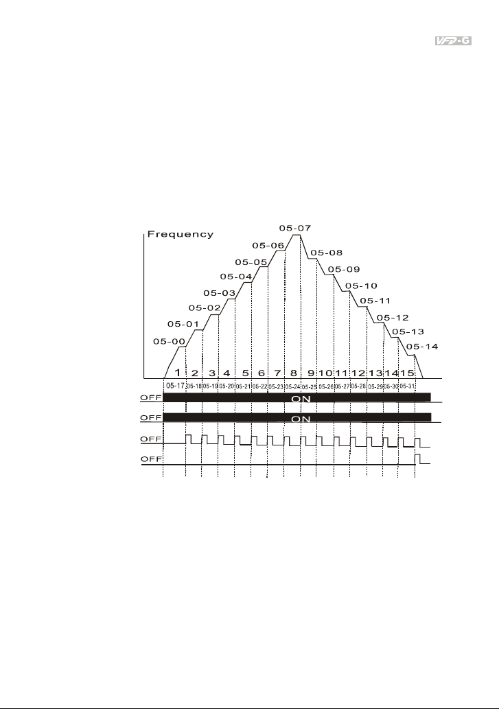
Chapter 4 Parameters|
Example 1 (Pr.05-15 = 1): Execute one cycle of the PLC program. Its relative parameter
settings are:
Pr.05-00 to 05-14: 1st to 15th step speeds (sets the frequency of each step speed)
Pr.04-00 to 04-03: Multi-Function Input Terminals (set one multi-function terminal as 32 - PLC
auto-operation).
Pr.03-00: Multi-Function Output Terminals (set a Multi-Function Terminal as 34-PLC
running indication, 35-PLC step completed or 36-PLC program completed).
Pr.05-16: Direction of the 1st to 15th step speeds.
Pr.05-17 to 05-31: Operation time setting for each corresponding step speed.
Program operation
command
Program operation
indication
Step operation
indication
Program operation
fulfillment indication
Note: The above diagram shows one complete PLC operation cycle. To restart this cycle, turn the
multi-function input terminal that designed as PLC program off and on again.
Example 2 (Pr.05-15 = 2): Continuously executes program cycles:
The diagram above shows the PLC program stepping through each speed. Set Pr.05-15 to 2 for
continuous program execution. To stop the PLC program, one must either pause the function or turn
it off. (Refer to Pr.04-00 to 04-03 values 32 and 33).
Revision July 2008, EG03, SW V1.06 4-47
Page 99

Chapter 4 Parameters|
g
Example 3 (Pr.05-15 = 3) Execute one cycle step by step:
The example below shows how the PLC can perform one cycle at a time, within in a complete cycle.
Each step will use the accel/decel times in Pr.01-09 to Pr.01-16. It should be noticed that the time
each step spends at its intended frequency is diminished, due to the time spent during accel/decel.
Frequency
Program operation
command
Pro
ram operation
indication
Step operation
indicati on
05-17
OFF
OFF
OFF
PLC operation execution one cycle step by step
05-02
05-01
05-00
12 3 4
05-18
t
ON
05-19
t
ON
ON
ON
ON
t
05-03
Time
05-20
05 - 16 PLC Forward/Reverse Motion
Settings 00 to 32767 (0:Forward, 1:Reverse) Factory Setting: 00
This parameter controls the direction of motion for the Multi-Step Speeds Pr.05-00 to Pr.05-14
during PLC mode. All other direction commands are invalid during the PLC mode.
Note: The equivalent 15-bit number is used to program the forward/reverse motion for each of the 15
speed steps. The binary notation for the 15-bit number must be translated into decimal notation
and then entered.
4-48 Revision July 2008, EG03, SW V1.06
Page 100

Chapter 4 Parameters|
Weigh ts
Bit
123456789101112131415 0
0=Forward
1=Reverse
Direct ion of Pr.05- 001st speed for
Direct ion of Pr.05-012nd speed for
Direction of Pr.05-023rd speed for
Direction of Pr.05-034th speed for
Direction of Pr.05-045th speed for
Direction of Pr.05-056th speed for
Direction of Pr.05-067th speed for
Direction of Pr.05-078th speed for
Direction of Pr.05-089th speed for
Direction of Pr.05-0910th speed for
Direct ion of Pr.05-1011th speed for
Direction of Pr.05-1112th speed for
Direction of 1 Pr.05-123th speed for
Direction of Pr.05-1314th speed for
Direction of Pr.05-1415th speed for
Weight s
Bit
The setting value = bit14x2 +14bit13x2 +....+bit2x2 +bit1x2 +bit0x2
Setting 05-16
NOTE:
14
2 =16384
2=51292=25682=12872=6462=32
2=1642=8
= 1x 2 +141x2 +1x2 +1x2 +1x2 +1x2 +1x2
=16384+2048 +1024+64+32+16+2
=19570
=19570
2 =8192132 =4096122 =2048112 =1024
3
13 210
11106541
2=422=2
0=Forward
1=Reverse
100111000110010 0
1
Directio n of Pr.05-00 , 1st speed = Forward
Direction of Pr.05-01,2nd speed=Reverse
Direction of ,Pr.05-02 3rd speed=Forward
Direction of ,Pr.05-03 4th speed=Forward
Direction of ,Pr.05-04 5th speed=Reverse
Direction of Pr.05-05,6th speed=Reverse
Direction of Pr.05-06,7th speed=Reverse
Direction of Pr.05-07,8th speed=Forward
Direction of Pr.05-08,9th speed=Forward
Direction of Pr.05-09,10th speed=Forward
Directio n of Pr.05-10,11th speed=Revers e
Directio n of Pr.05-11,12th speed=Revers e
Direction of 1Pr.05-12, 3th speed=Forward
Direction of Pr.05-13,14th speed=Forward
Direction of Pr.05-14,15 th speed=Rever se
10
5
0
2=1
Revision July 2008, EG03, SW V1.06 4-49
 Loading...