

Page 1
Page 2

Page 3

Page 4

Preface
Thank you for choosing DELTA’s multifunction VFD-EL Series. The VFD-EL Series is manufactured
with high-quality components and materials and incorporate the latest microprocessor technology
available.
This manual is to be used for the installation, parameter setting, troubleshooting, and daily
maintenance of the AC motor drive. To guarantee safe operation of the equipment, read the following
safety guidelines before connecting power to the AC motor drive. Keep this operating manual at
hand and distribute to all users for reference.
To ensure the safety of operators and equipment, only qualified personnel familiar with AC motor
drive are to do installation, start-up and maintenance. Always read this manual thoroughly before
using VFD-EL series AC Motor Drive, especially the WARNING, DANGER and CAUTION notes.
Failure to comply may result in personal injury and equipment damage. If you have any questions,
please contact your dealer.
PLEASE READ PRIOR TO INSTALLATION FOR SAFETY.
DANGER!
1. AC input power must be disconnected before any wiring to the AC motor drive is made.
2. A charge may still remain in the DC-link capacitors with hazardous voltages, even if the power
has been turned off. To prevent personal injury, please ensure that power has turned off before
opening the AC motor drive and wait ten minutes for the capacitors to discharge to safe voltage
levels.
3. Never reassemble internal components or wiring.
4. The AC motor drive may be destroyed beyond repair if incorrect cables are connected to the
input/output terminals. Never connect the AC motor drive output terminals U/T1, V/T2, and
W/T3 directly to the AC mains circuit power supply.
5. Ground the VFD-EL using the ground terminal. The grounding method must comply with the
laws of the country where the AC motor drive is to be installed. Refer to the Basic Wiring
Diagram.
6. VFD-EL series is used only to control variable speed of 3-phase induction motors, NOT for 1-
phase motors or other purpose.
7. VFD-EL series shall NOT be used for life support equipment or any life safety situation.
Page 5

WARNI NG!
1. DO NOT use Hi-pot test for internal components. The semi-conductor used in AC motor drive
easily damage by high-voltage.
2. There are highly sensitive MOS components on the printed circuit boards. These components
are especially sensitive to static electricity. To prevent damage to these components, do not
touch these components or the circuit boards with metal objects or your bare hands.
3. Only qualified persons are allowed to install, wire and maintain AC motor drives.
CAUTION!
1. DO NOT install the AC motor drive in a place subjected to high temperature, direct sunlight,
high humidity, excessive vibration, corrosive gases or liquids, or airborne dust or metallic
particles.
2. Some parameters settings can cause the motor to run immediately after applying power
3. Only use AC motor drives within specification. Failure to comply may result in fire, explosion or
electric shock.
4. To prevent personal injury, please keep children and unqualified people away from the
equipment.
5. When the motor cable between AC motor drive and motor is too long, the layer insulation of the
motor may be damaged. Please use a frequency inverter duty motor or add an AC output
reactor to prevent damage to the motor. Refer to appendix B Reactor for details.
6. The rated voltage for AC motor drive must be ≤ 240V (≤ 480V for 460V models) and the mains
supply current capacity must be ≤ 5000A RMS.
Page 6

Table of Contents
Preface ............................................................................................................. i
Table of Contents .......................................................................................... iii
Chapter 1 Introduction................................................................................ 1-1
1.1 Receiving and Inspection....................................................................1-2
1.1.1 Nameplate Information................................................................ 1-2
1.1.2 Model Explanation ...................................................................... 1-2
1.1.3 Series Number Explanation ........................................................ 1-3
1.1.4 Drive Frames and Appearances ................................................. 1-3
1.1.5 Remove Instructions ................................................................... 1-5
1.2 Preparation for Installation and Wiring................................................1-5
1.2.1 Ambient Conditions..................................................................... 1-6
1.2.2 DC-bus Sharing: Connecting the DC-bus of the AC Motor Drives in
Parallel.................................................................................................
1.3 Dimensions.........................................................................................1-9
Chapter 2 Installation and Wiring ..............................................................2-1
2.1 Wiring .................................................................................................2-2
2.2 External Wiring ...................................................................................2-8
2.3 Main Circuit.........................................................................................2-9
2.3.1 Main Circuit Connection.............................................................. 2-9
2.3.2 Main Circuit Terminals .............................................................. 2-11
2.4 Control Terminals .............................................................................2-12
1-8
Page 7

Chapter 3 Keypad and Start Up ..................................................................3-1
3.1 Description of the Digital Keypad ....................................................... 3-1
3.2 How to Operate the Digital Keypad .................................................... 3-3
3.3 Reference Table for the 7-segment LED Display of the Digital Keypad 34
3.4 Operation Method .............................................................................. 3-4
3.5 Trial Run ............................................................................................ 3-5
Chapter 4 Parameters..................................................................................4-1
4.1 Summary of Parameter Settings ........................................................ 4-2
4.2 Parameter Settings for Applications ................................................. 4-21
4.3 Description of Parameter Settings.................................................... 4-26
Chapter 5 Troubleshooting.........................................................................5-1
5.1 Over Current (OC).............................................................................. 5-1
5.2 Ground Fault ...................................................................................... 5-2
5.3 Over Voltage (OV).............................................................................. 5-2
5.4 Low Voltage (Lv) ................................................................................ 5-3
5.5 Over Heat (OH1) ................................................................................ 5-4
5.6 Overload ............................................................................................ 5-4
5.7 Keypad Display is Abnormal .............................................................. 5-5
5.8 Phase Loss (PHL) .............................................................................. 5-5
5.9 Motor cannot Run............................................................................... 5-6
5.10 Motor Speed cannot be Changed .................................................... 5-7
5.11 Motor Stalls during Acceleration....................................................... 5-8
5.12 The Motor does not Run as Expected.............................................. 5-8
5.13 Electromagnetic/Induction Noise...................................................... 5-9
Page 8

5.14 Environmental Condition...................................................................5-9
5.15 Affecting Other Machines ...............................................................5-10
Chapter 6 Fault Code Information and Maintenance................................ 6-1
6.1 Fault Code Information .......................................................................6-1
6.1.1 Common Problems and Solutions............................................... 6-1
6.1.2 Reset .......................................................................................... 6-5
6.2 Maintenance and Inspections .............................................................6-5
Appendix A Specifications ........................................................................ A-1
Appendix B Accessories ........................................................................... B-1
B.1 All Brake Resistors & Brake Units Used in AC Motor Drives............. B-1
B.1.1 Dimensions and Weights for Brake Resistors ............................ B-4
B.2 No Fuse Circuit Breaker Chart .......................................................... B-7
B.3 Fuse Specification Chart ................................................................... B-8
B.4 AC Reactor........................................................................................ B-9
B.4.1 AC Input Reactor Recommended Value..................................... B-9
B.4.2 AC Output Reactor Recommended Value..................................B-9
B.4.3 Applications .............................................................................. B-10
B.5 Zero Phase Reactor (RF220X00A) ................................................. B-12
B.6 Remote Controller RC-01................................................................ B-13
B.7 PU06 ............................................................................................... B-14
B.7.1 Description of the Digital Keypad VFD-PU06 ...........................B-14
B.7.2 Explanation of Display Message...............................................B-14
B.7.3 Operation Flow Chart ...............................................................B-15
B.8 Fieldbus Modules ............................................................................ B-16
Page 9

B.8.1 DeviceNet Communication Module (CME-DN01) .....................B-16
B.8.1.1 Panel Appearance and Dimensions ..................................B-16
B.8.1.2 Wiring and Settings ...........................................................B-16
B.8.1.3 Power Supply ....................................................................B-17
B.8.1.4 LEDs Display.....................................................................B-17
B.8.2 LonWorks Communication Module (CME-LW01) .....................B-17
B.8.2.1 Introduction .......................................................................B-17
B.8.2.2 Dimensions .......................................................................B-17
B.8.2.3 Specifications ....................................................................B-18
B.8.2.4 Wiring ................................................................................B-18
B.8.2.5 LED Indications .................................................................B-18
B.8.3 Profibus Communication Module (CME-PD01).........................B-19
B.8.3.1 Panel Appearance.............................................................B-19
B.8.3.2 Dimensions .......................................................................B-20
B.8.3.3 Parameters Settings in VFD-EL ........................................B-20
B.8.3.4 Power Supply ....................................................................B-20
B.8.3.5 PROFIBUS Address..........................................................B-20
B.8.4 CME-COP01 (CANopen) ..........................................................B-21
B.8.4.1 Product Profile...................................................................B-21
B.8.4.2 Specifications ....................................................................B-21
B.8.4.3 Components......................................................................B-22
B.8.4.4 LED Indicator Explanation & Troubleshooting...................B-23
B.9 MKE-EP & DIN Rail ......................................................................... B-25
B.9.1 MKE-EP ....................................................................................B-25
B.9.2 DIN Rail: MKEL-DRA (Only for frame A)...................................B-26
Page 10

Appendix C How to Select the Right AC Motor Drive.............................. C-1
C.1 Capacity Formulas ............................................................................C-2
C.2 General Precaution ...........................................................................C-4
C.3 How to Choose a Suitable Motor....................................................... C-5
Page 11

This page intentionally left blank
Page 12

Chapter 1 Introduction
The AC motor drive should be kept in the shipping carton or crate before installation. In order to
retain the warranty coverage, the AC motor drive should be stored properly when it is not to be used
for an extended period of time. Storage conditions are:
CAUTION!
1. Store in a clean and dry location free from direct sunlight or corrosive fumes.
2. Store within an ambient temperature range of -20
3. Store within a relative humidity range of 0% to 90% and non-condensing environment.
4. Store within an air pressure range of 86 kPA to 106kPA.
5. DO NOT place on the ground directly. It should be stored properly. Moreover, if the surrounding
environment is humid, you should put exsiccator in the package.
6. DO NOT store in an area with rapid changes in temperature. It may cause condensation and
frost.
7. If the AC motor drive is stored for more than 3 months, the temperature should not be higher
than 30 °C. Storage longer than one year is not recommended, it could result in the degradation
of the electrolytic capacitors.
8. When the AC motor drive is not used for longer time after installation on building sites or places
with humidity and dust, it’s best to move the AC motor drive to an environment as stated above.
°
C to +60 °C.
Revision August 2008, 2ELE, V1.02 1-1
Page 13
Chapter 1 Introduction|
A
1.1 Receiving and Inspection
This VFD-EL AC motor drive has gone through rigorous quality control tests at the factory before
shipment. After receiving the AC motor drive, please check for the following:
Check to make sure that the package includes an AC motor drive, the User Manual/Quick
Start and CD.
Inspect the unit to assure it was not damaged during shipment.
Make sure that the part number indicated on the nameplate corresponds with the part
number of your order.
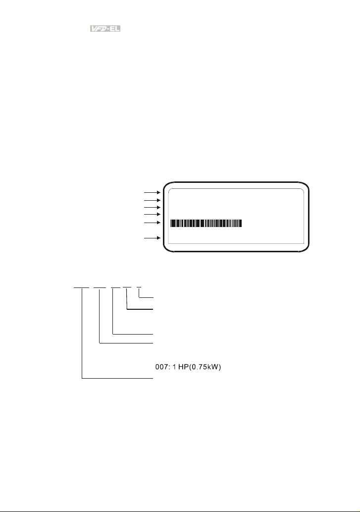
1.1.1 Nameplate Information
Example for 1HP/0.75kW 3-phase 230V AC motor drive
AC Drive Model
Input Spec.
Output Frequency Range
Serial Number & Bar Code
Output Spec.
Software Version
1.1.2 Model Explanation
23
007
VFD
EL
MODEL VFD007EL23A
:
INPUT :3PH 200-240V 50/60Hz 5.1A
OUTPUT :3PH 0-240V 4.2A 1.6kVA 0.75kW/1HP
FREQUENCY RANGE : 0.1~600Hz
007EL23A0T7140001
00.92
Version Type
A: Standard drive
Mains Input Voltage
11:115 phaseV 123:230 phaseV 3-
21: phase230V 143:460 phaseV 3 -
VFD-EL Series
Applicable motor capacity
002: 0.25 HP(0.2kW)
004: 0.5 HP(0.4kW)
015: 2 HP(1.5kW)
022: 3 HP(2.2kW)
037: 5 HP(3.7kW)
Series Name ( ariable requency rive)
VF D
1-2 Revision August 2008, 2ELE, V1.02
Page 14
Chapter 1 Introduction|
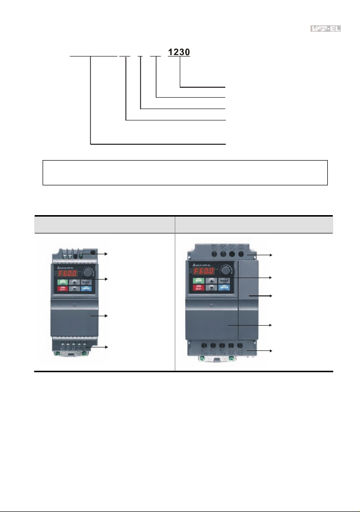
1.1.3 Series Number Explanation
0170T007EL23A
Production number
Production week
Production year 2007
Production factory
230V 3-phase 1HP(0.75kW)
T: Taoyuan, W: Wujiang
Model
If the nameplate information does not correspond to your purchase order or if there are
any problems, please contact your distributor.
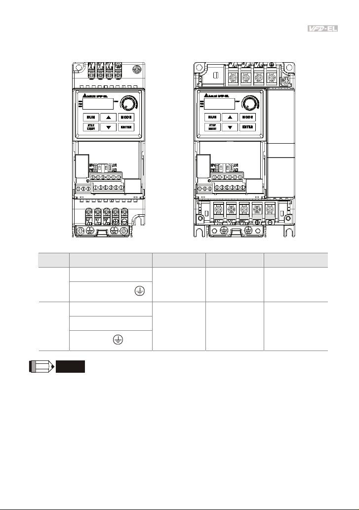
1.1.4 Drive Frames and Appearances
0.25-2HP/0.2-1.5kW (Frame A) 1-5HP/0.75-3.7kW (Frame B)
Input terminals
(R/L1, S/ L2, T/L3)
Digital keypad
Control board cover
Output terminals
(U/T1, V/T2, W/T3)
Revision August 2008, 2ELE, V1.02 1-3
Input terminals cover
(R/L1, S/L2, T/L3)
Digital keypad
Case body
Control board cover
Output terminals cover
(U/T1, V/T2, W/T3)
Page 15
Chapter 1 Introduction|
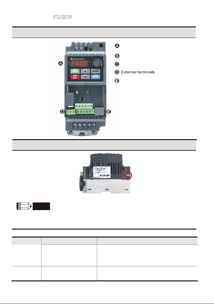
Internal Structure
RFI Jumper Location
Digital keypad
NPN/PNP
ACI/AVI
RS485 port (RJ- 45)
at the right side
NOTE
RFI jumper is near the input terminals as shown in the above figure and can be removed by taking
off screws.
Frame Power range Models
VFD002EL11A/21A/23A,
A 0.25-2hp (0.2-1.5kW)
B 1-5hp (0.75-3.7kW)
1-4 Revision August 2008, 2ELE, V1.02
VFD004EL11A/21A/23A/43A,
VFD007EL21A/23A/43A, VFD015EL23A/43A
VFD007EL11A, VFD015EL21A,
VFD022EL21A/23A/43A, VFD037EL23A/43A
Page 16
Chapter 1 Introduction|
RFI Jumper
RFI Jumper: The AC motor drive may emit the electrical noise. The RFI jumper is used to suppress
the interference (Radio Frequency Interference) on the power line.
Main power isolated from earth:
If the AC motor drive is supplied from an isolated power (IT power), the RFI jumper must be cut off.
Then the RFI capacities (filter capacitors) will be disconnected from ground to prevent circuit damage
(according to IEC 61800-3) and reduce earth leakage current.
CAUTION!
1. After applying power to the AC motor drive, do not cut off the RFI jumper. Therefore,
please make sure that main power has been switched off before cutting the RFI jumper.
2. The gap discharge may occur when the transient voltage is higher than 1,000V. Besides,
electro-magnetic compatibility of the AC motor drives will be lower after cutting the RFI
jumper.
3. Do NOT cut the RFI jumper when main power is connected to earth.
4. The RFI jumper cannot be cut when Hi-pot tests are performed. The mains power and
motor must be separated if high voltage test is performed and the leakage currents are
too high.
5. To prevent drive damage, the RFI jumper connected to ground shall be cut off if the AC
motor drive is installed on an ungrounded power system or a high resistance-grounded
(over 30 ohms) power system or a corner grounded TN system.
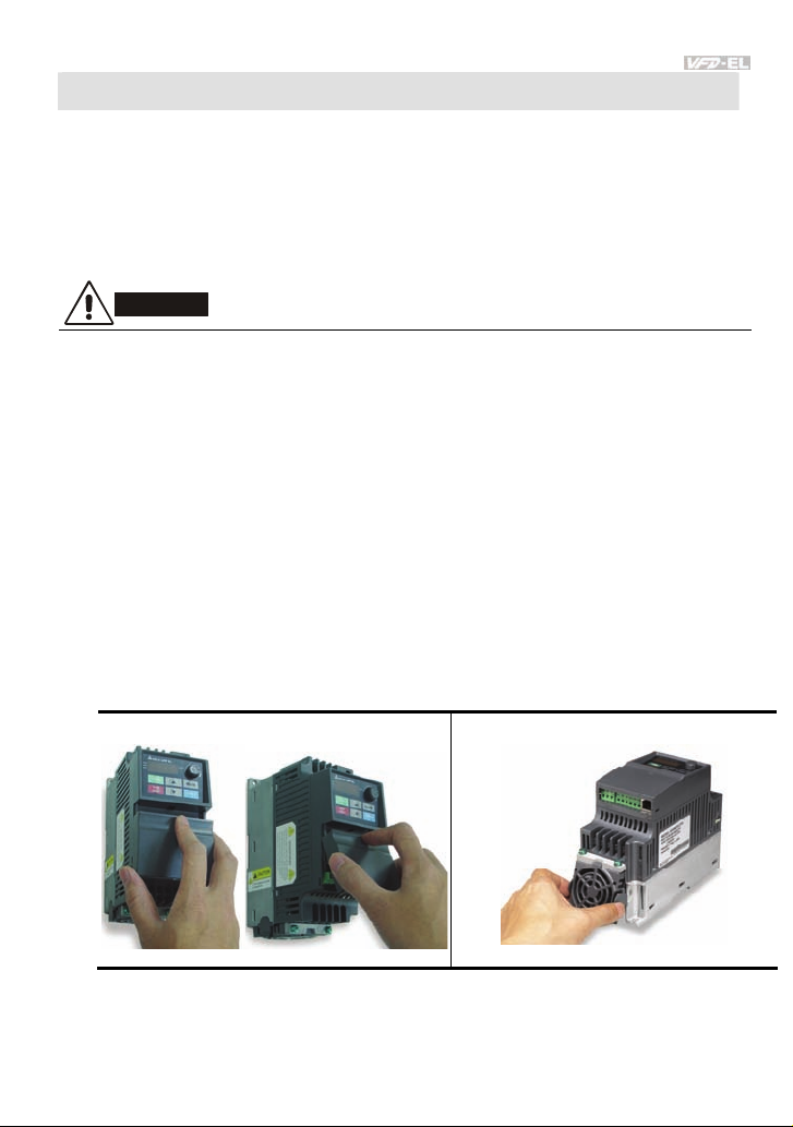
1.1.5 Remove Instructions
Remove Front Cover
Step 1 Step 2
Remove Fan
1.2 Preparation for Installation and Wiring
Revision August 2008, 2ELE, V1.02 1-5
Page 17
Chapter 1 Introduction|
1.2.1 Ambient Conditions
Install the AC motor drive in an environment with the following conditions:
Air Temperature:
Relative Humidity: <90%, no condensation allowed
Operation
Storage
Transportation
Pollution
Degree
Minimum Mounting Clearances
Atmosphere
pressure:
Installation Site
Altitude:
Vibration:
Temperature: -20°C ~ +60°C (-4°F ~ 140°F)
Relative Humidity: <90%, no condensation allowed
Atmosphere
pressure:
Vibration:
2: good for a factory type environment.
-10 ~ +50°C (14 ~ 122°F) for UL & cUL
-10 ~ +40°C (14 ~ 104°F) for side-by-side mounting
86 ~ 106 kPa
<1000m
<20Hz: 9.80 m/s2 (1G) max
20 ~ 50Hz: 5.88 m/s2 (0.6G) max
86 ~ 106 kPa
<20Hz: 9.80 m/s2 (1G) max
20 ~ 50Hz: 5.88 m/s2 (0.6G) max
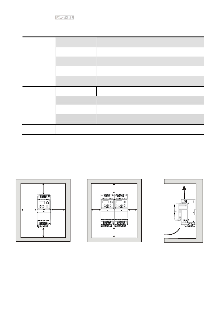
Frame A Mounting Clearances
Option 1 (-10 to +50°C) Option 2 (-10 to +40°C)
120mm
m
m
0
5
120mm
Air flow
120mm
m
m
0
5
m
m
0
5
120mm
m
m
0
5
Air Flow
1-6 Revision August 2008, 2ELE, V1.02
Page 18
Chapter 1 Introduction|
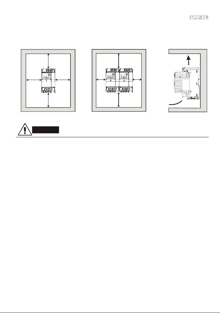
Frame B Mounting Clearances
Option 1 (-10 to +50°C) Option 2 (-10 to +40°C)
150mm
m
m
0
5
150mm
m
m
0
5
150mm
m
m
0
5
150mm
m
m
0
5
Air flow
Air Flow
CAUTION!
1. Operating, storing or transporting the AC motor drive outside these conditions may cause
damage to the AC motor drive.
2. Failure to observe these precautions may void the warranty!
3. Mount the AC motor drive vertically on a flat vertical surface object by screws. Other directions
are not allowed.
4. The AC motor drive will generate heat during operation. Allow sufficient space around the unit
for heat dissipation.
5. The heat sink temperature may rise to 90°C when running. The material on which the AC motor
drive is mounted must be noncombustible and be able to withstand this high temperature.
6. When AC motor drive is installed in a confined space (e.g. cabinet), the surrounding
temperature must be within 10 ~ 40°C with good ventilation. DO NOT install the AC motor drive
in a space with bad ventilation.
7. Prevent fiber particles, scraps of paper, saw dust, metal particles, etc. from adhering to the
heatsink.
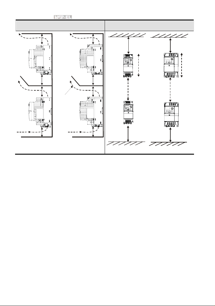
8. When installing multiple AC more drives in the same cabinet, they should be adjacent in a row
with enough space in-between. When installing one AC motor drive below another one, use a
metal separation between the AC motor drives to prevent mutual heating.
Revision August 2008, 2ELE, V1.02 1-7
Page 19
Chapter 1 Introduction|
Installation with Metal Separation Installation without Metal Separation
120mm
150mm
120mm
150mm
A
120mm
120mm
120mm
Frame A
Air flow
150mm
150mm
150mm
Frame B
A
120mm
Frame A
B
150mm
Frame B
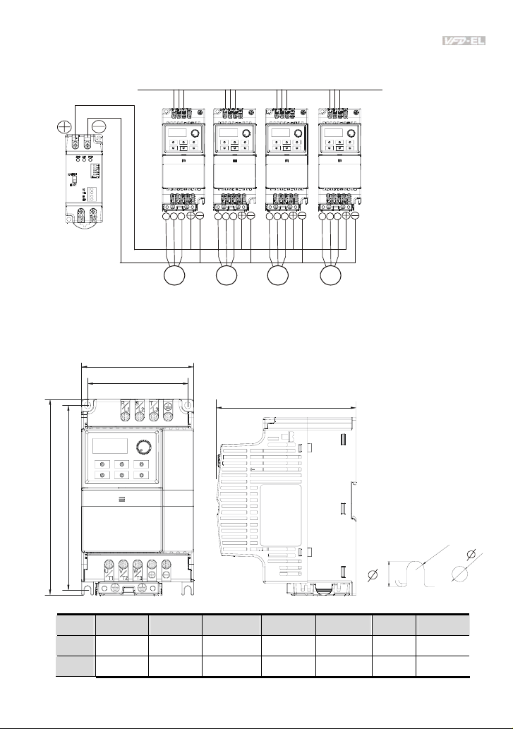
1.2.2 DC-bus Sharing: Connecting the DC-bus of the AC Motor Drives in Parallel
1. This function is not for 115V models.
2. The AC motor drives can absorb mutual voltage that generated to DC bus when
deceleration.
3. Enhance brake function and stabilize the voltage of the DC bus.
4. The brake module can be added to enhance brake function after connecting in parallel.
5. Only the same power system can be connected in parallel.
6. It is recommended to connect 5 AC motor drives in parallel (no limit in horsepower).
B
1-8 Revision August 2008, 2ELE, V1.02
Page 20
Chapter 1 Introduction|
power should be applied at the same time
(only the same power system can be connected in parallel)
Power 208/220/230/380/440/480 (depend on models)
U V W U V W U V W U V W
Braking
modules
IM IM IM IM
For frame A and B, terminal + (-) is connected to the terminal + (-) of the braking module.
1.3 Dimensions
(Dimensions are in millimeter and [inch])
H H1
Frame W W1 H H1 D Ø ØD
A 72.0[2.83] 59.0[2.32] 174.0[6.86] 151.6[5.97] 136.0[5.36] 5.4[0.21] 2.7[0.11]
B 100.0[3.94] 89.0[3.50] 174.0[6.86] 162.9[6.42] 136.0[5.36] 5.4[0.21] 2.7[0.11]
Revision August 2008, 2ELE, V1.02 1-9
W
W1
D
D
Page 21

Chapter 1 Introduction|
NOTE
Frame A: VFD002EL11A/21A/23A, VFD004EL11A/21A/23A/43A, VFD007EL21A/23A/43A,
VFD015EL23A/43A
Frame B: VFD007EL11A, VFD015EL21A, VFD022EL21A/23A/43A, VFD037EL23A/43A
1-10 Revision August 2008, 2ELE, V1.02
Page 22

Chapter 2 Installation and Wiring
After removing the front cover, check if the power and control terminals are clear. Be sure to observe
the following precautions when wiring.
General Wiring Information
Applicable Codes
All VFD-EL series are Underwriters Laboratories, Inc. (UL) and Canadian Underwriters
Laboratories (cUL) listed, and therefore comply with the requirements of the National
Electrical Code (NEC) and the Canadian Electrical Code (CEC).
Installation intended to meet the UL and cUL requirements must follow the instructions
provided in “Wiring Notes” as a minimum standard. Follow all local codes that exceed UL
and cUL requirements. Refer to the technical data label affixed to the AC motor drive and
the motor nameplate for electrical data.
The "Line Fuse Specification" in Appendix B, lists the recommended fuse part number for
each VFD-EL Series part number. These fuses (or equivalent) must be used on all
installations where compliance with U.L. standards is a required.
CAUTION!
1. Make sure that power is only applied to the R/L1, S/L2, T/L3 terminals. Failure to comply may
result in damage to the equipment. The voltage and current should lie within the range as
indicated on the nameplate.
2. All the units must be grounded directly to a common ground terminal to prevent lightning strike
or electric shock.
3. Please make sure to fasten the screw of the main circuit terminals to prevent sparks which is
made by the loose screws due to vibration.
4. Check following items after finishing the wiring:
A. Are all connections correct?
B. No loose wires?
C. No short-circuits between terminals or to ground?
Revision August 2008, 2ELE, V1.02 2-1
Page 23

Chapter 2 Installation and Wiring|
DANGER!
1. A charge may still remain in the DC bus capacitors with hazardous voltages even if the power
has been turned off. To prevent personal injury, please ensure that the power is turned off and
wait ten minutes for the capacitors to discharge to safe voltage levels before opening the AC
motor drive.
2. Only qualified personnel familiar with AC motor drives is allowed to perform installation, wiring
and commissioning.
3. Make sure that the power is off before doing any wiring to prevent electric shock.
2.1 Wiring
Users must connect wires according to the circuit diagrams on the following pages. Do not plug a
modem or telephone line to the RS-485 communication port or permanent damage may result. The
pins 1 & 2 are the power supply for the optional copy keypad only and should not be used for RS-485
communication.
2-2 Revision August 2008, 2ELE, V1.02
Page 24
Chapter 2 Installation and Wiring|
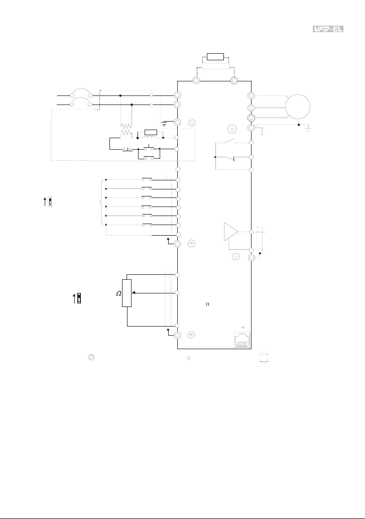
Figure 1 for models of VFD-EL Series
VFD002EL11A/21A, VFD004EL11A/21A, VFD007EL11A/21A, VFD015 EL21A, VFD022EL21A
brake resistor
BR
(optional)
BUE
brake unit
Fuse/NFB(No Fuse Breaker)
R(L1)
S(L2)
Recommended Circuit
when power supply
is turned OFF by a
fault output
If the fault occurs, the
contact will be ON to
turn off the power and
protect the power system.
Factory setting:
NPN Mode
NPN
PNP
Please refer to Figure 3
for w iring of N PN
mode and PNP
mode.
Sw1
Factory setting:
AVI M ode
AVI
ACI
Factory
sett ing
Sw2
SA
MC
ON
OFF
FWD/Stop
REV/Sto p
Multi-s tep 1
Multi-step 2
Multi-step 3
Multi-step 4
Digital Signal Common
3
2
5K
1
Analog Signal Common
Main circuit (power) terminals
MC
(optional)
+
R(L1)
S(L2)
E
RB
RC
+24V
MI1
MI2
MI3
MI4
MI5
MI6
DCM
E
+10V
Power supply
+10V/3mA
AVI /AC I
Master Frequency
0- 10V 47K
/4-20mA
ACM
E
Control circuit terminals
-
U(T1)
V(T2)
W(T3)
E
RA
Multi-function contact output
Re fer t o ch apt er 2. 4 fo r de tai ls .
RB
Factory setting is
malfunction indication
RC
AFM
ACM
8
Analog Multi-function Output
Ter m in a l
Refer to chapter 2.4 for details.
Analog Signal common
E
Factory setting: output frequency
RS-485
Seri al interf ace
1: Reserved
2: E V
3: GND
4: S G-
1
5: SG+
6: Reserved
7: Reserved
8: Reserved
Shielded leads & Cable
Motor
IM
3~
Revision August 2008, 2ELE, V1.02 2-3
Page 25
Chapter 2 Installation and Wiring|
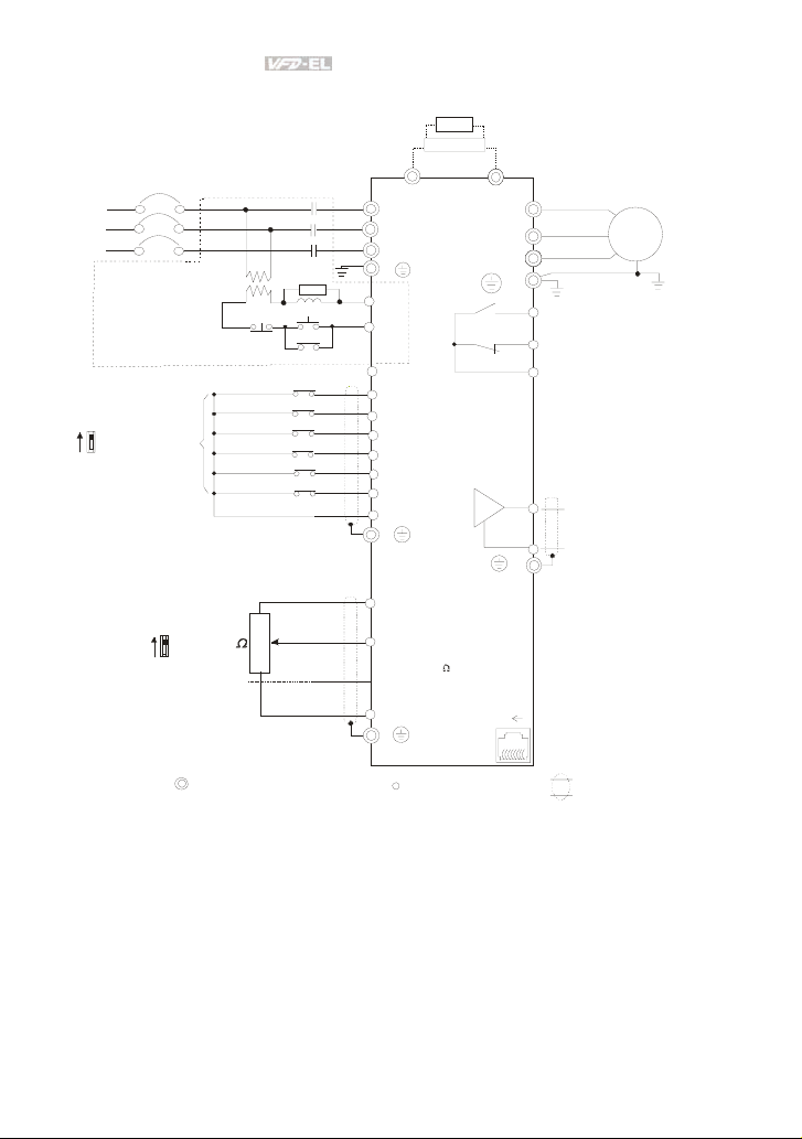
Figur e 2 for model s of VFD-EL Series
VFD002EL2 3A, VFD004EL23A/43A, VFD007EL23A /43A, VFD015EL2 3A/43A,
VFD022EL2 3A/43A, VFD037EL23A/43A
Fuse/NFB(No Fuse Breaker)
R(L1)
S(L2)
T(L3)
Recommended Circuit
when power supply
is turned OFF by a
fault output.
If the fault occurs, the
contact will be ON to
turn off the power and protect the power system.
Factory setting:
NPN Mode
NPN
PNP
Please refer to Figure 3
fo r wir ing o f NPN
mode and PNP
mode.
Sw1
Factory
setting
OFF
FWD/Stop
REV/Sto p
Multi-step 1
Multi-step 2
Multi-step 3
Multi-s tep 4
Digital Signal Common
+
R(L1)
S(L2)
T(L3)
E
SA
ON
MC
RB
RC
MC
+24V
MI1
MI2
MI3
MI4
MI5
MI6
DCM
E
BR
BUE
brake unit
(optional)
brake resistor
(o ptio nal)
-
U(T1)
V(T2)
W(T3)
E
RA
RB
RC
AFM
ACM
E
Factory setting:
AVI Mode
AVI
Sw2
ACI
Main circuit (power) terminals
3
2
5K
1
Analog Signal Common
+10V
Power supply
+10V/3mA
AVI/ACI
Master Frequency
0-10V 47K
/4-20mA
ACM
E
Control circuit terminals
1
8
Motor
IM
3~
Multi-function contact output
Refer to chapter 2.4 for details.
Factory setting is
malfunction indication
Analog Multi-function Output
Terminal
Refer to chapter 2.4 for details.
Analog Signal common
Factory setting: output frequency
RS-485
Serial interface
1: Reserved
2: E V
3: GND
4: S G-
5: SG+
6: Reserved
7: Reserved
8:
Reserved
Shielded leads & Cable
2-4 Revision August 2008, 2ELE, V1.02
Page 26
Chapter 2 Installation and Wiring|
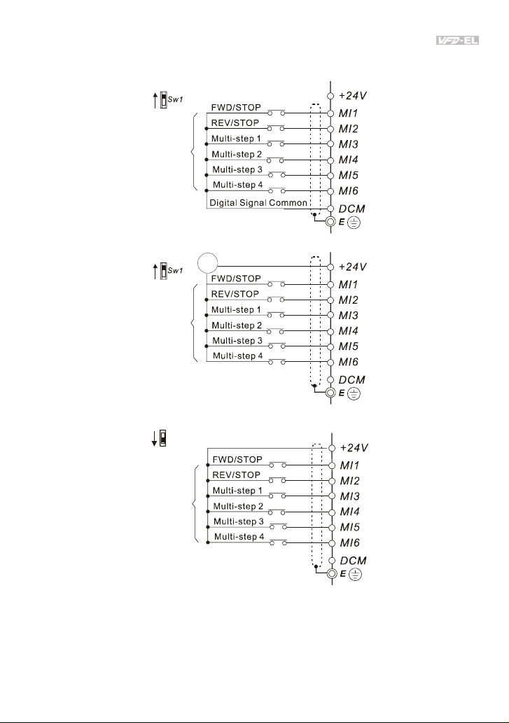
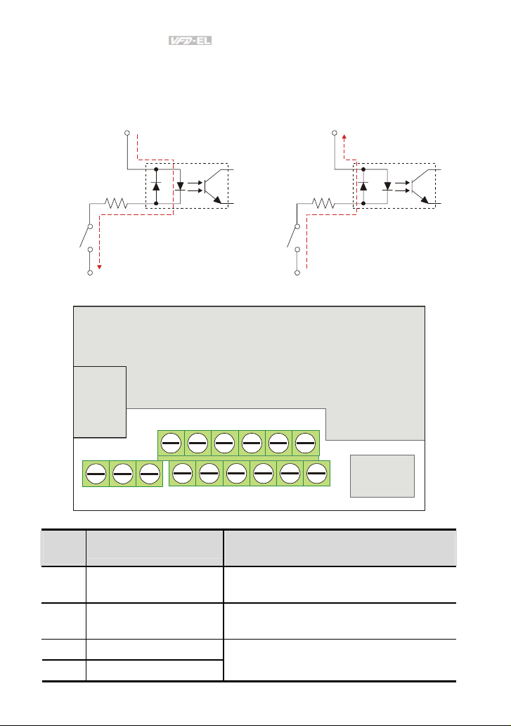
Figure 3 Wiring for NPN mode and PNP mode
A. NPN mode without external power
NPN
PNP
Factory
setting
B. NPN mode with external power
NPN
PNP
Factory
setting
C. PNP mode without external power
NPN
Sw1
PNP
Factory
setting
-
24
Vdc
+
Revision August 2008, 2ELE, V1.02 2-5
Page 27
Chapter 2 Installation and Wiring|
D. PNP mode with external power
NPN
Sw1
PNP
Factory
setting
+
24
Vdc
-
CAUTION!
1. The wiring of main circuit and control circuit should be separated to prevent erroneous actions.
2. Please use shield wire for the control wiring and not to expose the peeled-off net in front of the
terminal.
3. Please use the shield wire or tube for the power wiring and ground the two ends of the shield
wire or tube.
4. Damaged insulation of wiring may cause personal injury or damage to circuits/equipment if it
comes in contact with high voltage.
5. The AC motor drive, motor and wiring may cause interference. To prevent the equipment
damage, please take care of the erroneous actions of the surrounding sensors and the
equipment.
6. When the AC drive output terminals U/T1, V/T2, and W/T3 are connected to the motor terminals
U/T1, V/T2, and W/T3, respectively. To permanently reverse the direction of motor rotation,
switch over any of the two motor leads.
7. With long motor cables, high capacitive switching current peaks can cause over-current, high
leakage current or lower current readout accuracy. To prevent this, the motor cable should be
less than 20m for 3.7kW models and below. And the cable should be less than 50m for 5.5kW
models and above. For longer motor cables use an AC output reactor.
8. The AC motor drive, electric welding machine and the greater horsepower motor should be
grounded separately.
9. Use ground leads that comply with local regulations and keep them as short as possible.
10. No brake resistor is built in the VFD-EL series, it can install brake resistor for those occasions
that use higher load inertia or frequent start/stop. Refer to Appendix B for details.
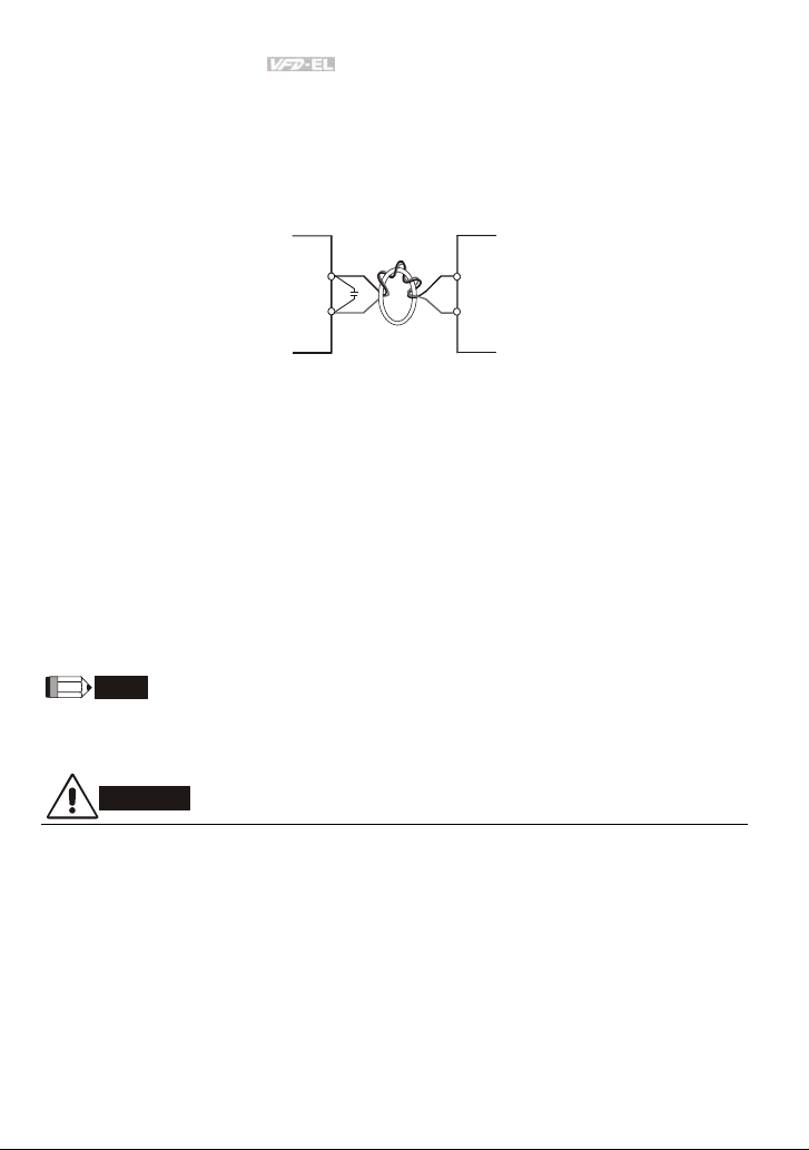
11. Multiple VFD-EL units can be installed in one location. All the units should be grounded directly
to a common ground terminal, as shown in the figure below. Ensure there are no ground
loops.
2-6 Revision August 2008, 2ELE, V1.02
Page 28
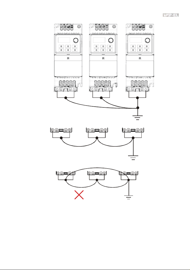
Chapter 2 Installation and Wiring|
Excellent
Good
Not allowed
Revision August 2008, 2ELE, V1.02 2-7
Page 29
Chapter 2 Installation and Wiring|
y
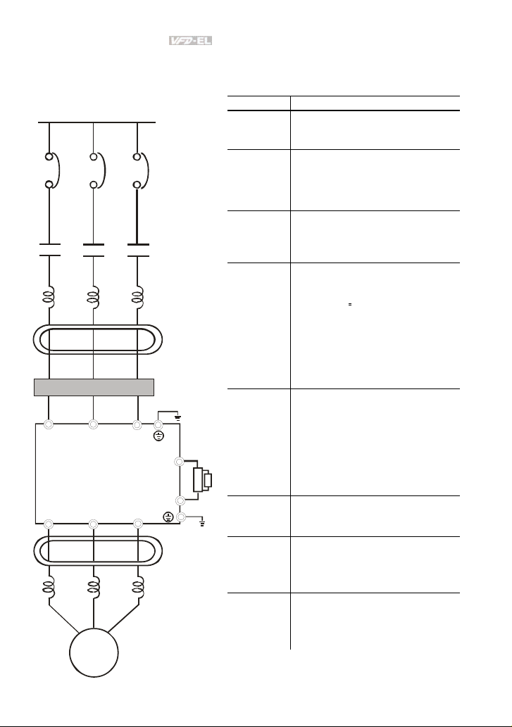
2.2 External Wiring
Power Suppl
EMI Filter
R/L1
U/T1 V/T2
S/L2
Motor
T/L3
W/T3
FUSE/NFB
Magnetic
cont actor
Input AC
Line Reactor
Zero-phase
Reactor
+
-
Zero-phase
Reactor
Outpu t AC
Line Reactor
Brak unit
Brak e resi stor
BR
BUE
Items Explanations
Power
supply
Please follow the specific power
supply requirements shown in
Appendix A.
There may be an inrush current
Fuse/NFB
(Optional)
during power up. Please check the
chart of Appendix B and select the
correct fuse with rated current. Use of
an NFB is optional.
Magnetic
contactor
(Optional)
Please do not use a Magnetic
contactor as the I/O switch of the AC
motor drive, as it will reduce the
operating life cycle of the AC drive.
Used to improve the input power
factor, to reduce harmonics and
provide protection from AC line
Input AC
Line Reactor
(Optional)
disturbances.
spikes, short interruptions, etc.). AC
line reactor should be installed when
the power supply capacity is 500kVA
or more or advanced capacity is
(surges, switching
activated. The wiring distance should
be
10m. Refer to appendix B for
≤
details.
Zero phase reactors are used to
Zero-phase
Reactor
(Ferrite Core
Common
Choke)
(Optional)
reduce radio noise especially when
audio equipment is installed near the
inverter. Effective for noise reduction
on both the input and output sides.
Attenuation quality is good for a wide
range from AM band to 10MHz.
Appendix B specifies the zero phase
reactor. (RF220X00A)
It is used to reduce electromagnetic
EMI filter
interference. All 230V and 460V
models are built-in EMI filter.
Brake
Resistor and
Brake Unit
(Optional)
Output AC
Line Reactor
(Optional)
Used to reduce the deceleration time
of the motor. Please refer to the chart
in Appendix B for specific Brake
Resistors.
Motor surge voltage amplitude
depends on motor cable length. For
applications with long motor cable
(>20m), it is necessary to install a
2-8 Revision August 2008, 2ELE, V1.02
Page 30
Chapter 2 Installation and Wiring|
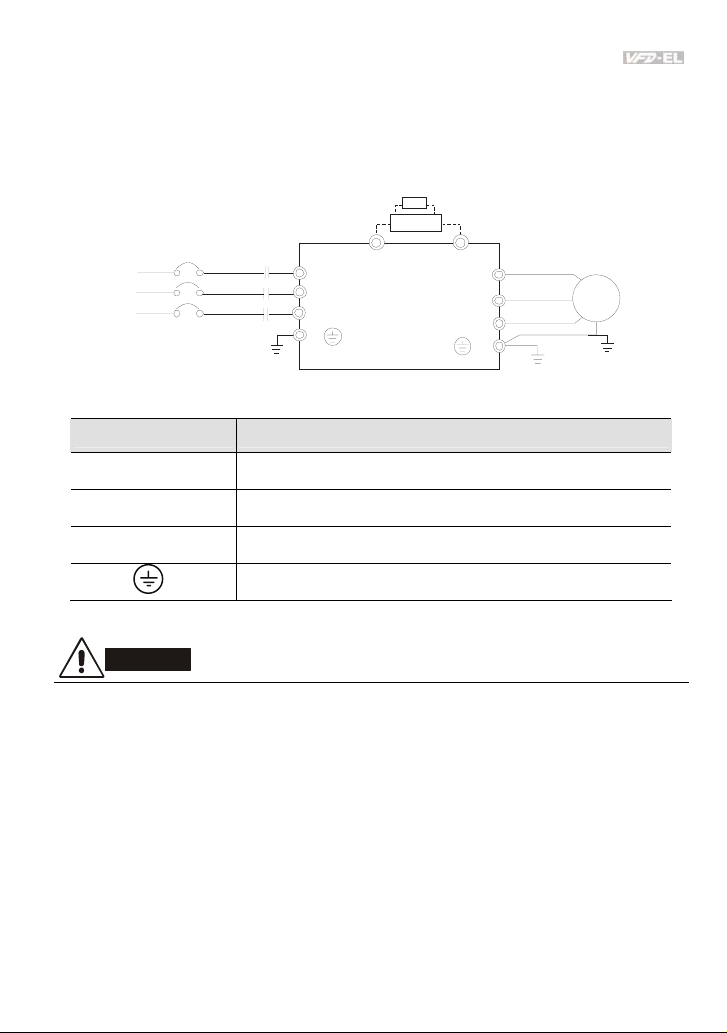
2.3 Main Circuit
2.3.1 Main Circuit Connection
No fuse breaker
( NFB)
R
S
T
MC
Brake Resistor(Optional)
R(L1)
S(L2)
T(L3)
E
BR
BUE
+
Brake Unit
(Op tiona l)
-
U(T1)
V(T2)
W(T3)
Motor
IM
3~
E
Terminal Symbol Explanation of Terminal Function
R/L1, S/L2, T/L3
U/T1, V/T2, W/T3
+, -
AC line input terminals (1-phase/3-phase)
AC drive output terminals for connecting 3-phase induction motor
Connections for External Brake unit (BUE series)
Earth connection, please comply with local regulations.
CAUTION!
Mains power terminals (R/L1, S/L2, T/L3)
Connect these terminals (R/L1, S/L2, T/L3) via a non-fuse breaker or earth leakage
breaker to 3-phase AC power (some models to 1-phase AC power) for circuit protection. It
is unnecessary to consider phase-sequence.
It is recommended to add a magnetic contactor (MC) in the power input wiring to cut off
power quickly and reduce malfunction when activating the protection function of AC motor
drives. Both ends of the MC should have an R-C surge absorber.
Please make sure to fasten the screw of the main circuit terminals to prevent sparks
which is made by the loose screws due to vibration.
Revision August 2008, 2ELE, V1.02 2-9
Page 31

Chapter 2 Installation and Wiring|
Please use voltage and current within the regulation shown in Appendix A.
When using a GFCI (Ground Fault Circuit Interrupter), select a current sensor with
sensitivity of 200mA, and not less than 0.1-second detection time to avoid nuisance
tripping. For specific GFCI of the AC motor drive, please select a current sensor with
sensitivity of 30mA or above.
Do NOT run/stop AC motor drives by turning the power ON/OFF. Run/stop AC motor
drives by RUN/STOP command via control terminals or keypad. If you still need to
run/stop AC drives by turning power ON/OFF, it is recommended to do so only ONCE per
hour.
Do NOT connect 3-phase models to a 1-phase power source.
Output terminals for main circuit (U, V, W)
The factory setting of the operation direction is forward running. The method to control the
operation direction is to set by the communication parameters. Please refer to the group 9
for details.
When it needs to install the filter at the output side of terminals U/T1, V/T2, W/T3 on the
AC motor drive. Please use inductance filter. Do not use phase-compensation capacitors
or L-C (Inductance-Capacitance) or R-C (Resistance-Capacitance), unless approved by
Delta.
DO NOT connect phase-compensation capacitors or surge absorbers at the output
terminals of AC motor drives.
Use well-insulated motor, suitable for inverter operation.
Terminals [+, -] for connecting brake resistor
All VFD-EL series don’t have a built-in brake chopper. Please connect an external
optional brake unit (BUE-series) and brake resistor. Refer to BUE series user manual for
details.
When not used, please leave the terminals [+, -] open.
2-10 Revision August 2008, 2ELE, V1.02
Page 32
Chapter 2 Installation and Wiring|
2.3.2 Main Circuit Terminals
Frame A Frame B
Frame Power Terminals Torque Wire Wire type
A
R/L1, S/L2, T/L3
U/T1, V/T2, W/T3,
R/L1, S/L2, T/L3
NOTE
U/T1, V/T2, W/T3
+, -,
B
Frame A: VFD002EL11A/21A/23A, VFD004EL11A/21A/23A/43A, VFD007EL21A/23A/43A,
VFD015EL23A/43A
Frame B: VFD007EL11A, VFD015EL21A, VFD022EL21A/23A/43A, VFD037EL23A/43A
Revision August 2008, 2ELE, V1.02 2-11
14.2-16.3kgf-cm
(12-14in-lbf)
16.3-19.3kgf-cm
(14-17in-lbf)
12-18 AWG.
(3.3-0.8mm
8-18 AWG. (8.4-
0.8mm
2
2
)
Copper only, 75
)
Copper only, 75
o
C
o
C
Page 33
Chapter 2 Installation and Wiring|
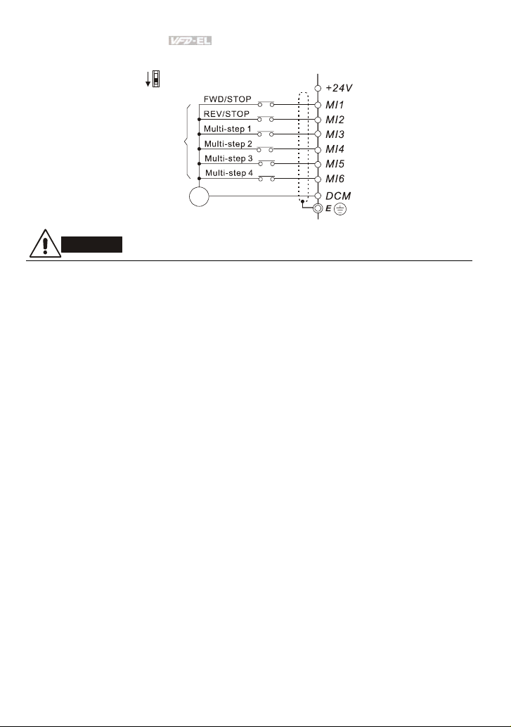
2.4 Control Terminals
Circuit diagram for digital inputs (NPN current 16mA.)
NPN Mode
+24V
PNP Mode
+24V
1
2
2
1
DCM
The position of the control terminals
MI2 MI4 MI6 DCM ACMAFM
RA
Terminal symbols and functions
Terminal
Symbol
MI1 Forward-Stop command
MI2 Reverse-Stop command
MI3 Multi-function Input 3
MI4 Multi-function Input 4
RC
RB
Terminal Function
4
3
2
1
DCM
1
2
10VMI1 MI3 MI524V AVI
RS-485
Factory Settings (NPN mode)
ON: Connect to DCM
ON: Run in MI1 direction
OFF: Stop acc. to Stop Method
ON: Run in MI2 direction
OFF: Stop acc. to Stop Method
Refer to Pr.04.05 to Pr.04.08 for programming the
Multi-function Inputs.
4
3
2-12 Revision August 2008, 2ELE, V1.02
Page 34
Chapter 2 Installation and Wiring|
AFMA
Terminal
Symbol
Terminal Function
MI5 Multi-function Input 5
ON: the activation current is 5.5mA.
OFF: leakage current tolerance is 10μA.
Factory Settings (NPN mode)
ON: Connect to DCM
MI6 Multi-function Input 6
+24V DC Voltage Source +24VDC, 50mA used for PNP mode.
DCM Digital Signal Common
Multi-function Relay output
RA
(N.O.) a
Common for digital inputs and used for NPN
mode.
Resistive Load:
5A(N.O.)/3A(N.C.) 240VAC
5A(N.O.)/3A(N.C.) 24VDC
Multi-function Relay output
RB
(N.C.) b
RC Multi-function Relay common
Inductive Load:
1.5A(N.O.)/0.5A(N.C.) 240VAC
1.5A(N.O.)/0.5A(N.C.) 24VDC
Refer to Pr.03.00 for programming
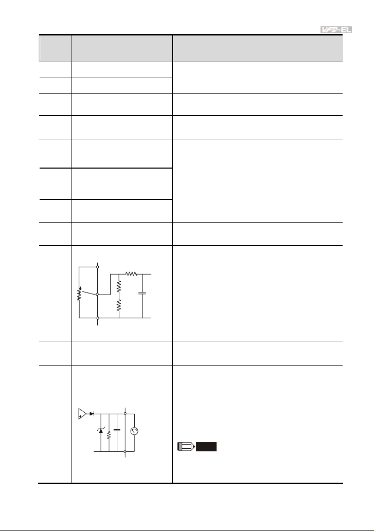
+10V Potentiometer power supply +10VDC 3mA
Analog voltage Input
AVI
+10V
AVI
AVI cir cuit
Impedance: 47kΩ
Resolution: 10 bits
Range: 0 ~ 10VDC/4~20mA =
0 ~ Max. Output Frequency
(Pr.01.00)
Analog control signal
ACM
(common)
ACM
internal circuit
Selection: Pr.02.00, Pr.02.09, Pr.10.00
Set-up: Pr.04.14 ~ Pr.04.17
Common for AVI= and AFM
0 to 10V, 2mA
Impedance: 47Ω
Analog output meter
ACM circuit
AFM
internal circuit
0~10V
potentiometer
Max. 2mA
CM
Output current 2mA max
Resolution: 8 bits
Range: 0 ~ 10VDC
Function: Pr.03.03 to Pr.03.04
NOTE
The voltage output type for this analog signal is
PWM. It needs to read value by the movable coil
meter and is not suitable for A/D signal conversion.
NOTE: Control signal wiring size: 18 AWG (0.75 mm2) with shielded wire.
Revision August 2008, 2ELE, V1.02 2-13
Page 35
Chapter 2 Installation and Wiring|
Analog inputs (AVI, ACM)
Analog input signals are easily affected by external noise. Use shielded wiring and keep it
as short as possible (<20m) with proper grounding. If the noise is inductive, connecting
the shield to terminal ACM can bring improvement.
If the analog input signals are affected by noise from the AC motor drive, please connect
a capacitor (0.1μF and above) and ferrite core as indicated in the following diagrams:
C
ferrite core
AVI
ACM
wind each wires 3 times or more around the core
Digital inputs (MI1~MI6, DCM)
When using contacts or switches to control the digital inputs, please use high quality
components to avoid contact bounce.
General
Keep control wiring as far away as possible from the power wiring and in separate
conduits to avoid interference. If necessary let them cross only at 90º angle.
The AC motor drive control wiring should be properly installed and not touch any live
power wiring or terminals.
NOTE
If a filter is required for reducing EMI (Electro Magnetic Interference), install it as close as
possible to AC drive. EMI can also be reduced by lowering the Carrier Frequency.
DANGER!
Damaged insulation of wiring may cause personal injury or damage to circuits/equipment if it comes
in contact with high voltage.
2-14 Revision August 2008, 2ELE, V1.02
Page 36

Chapter 2 Installation and Wiring|
The specification for the control terminals
The position of the control terminals
10VMI1 MI3 MI524V AVI
RS-485
RB
RC
RA
Frame Torque Wire
A, B 5.1-8.1kgf-cm (4.4-7in-lbf) 16-24 AWG. (1.3-0.2mm2)
MI2 MI4 MI6 DCM ACMAFM
NOTE
Frame A: VFD002EL11A/21A/23A, VFD004EL11A/21A/23A/43A, VFD007EL21A/23A/43A,
VFD015EL23A/43A
Frame B: VFD007EL11A, VFD015EL21A, VFD022EL21A/23A/43A, VFD037EL23A/43A
Revision August 2008, 2ELE, V1.02 2-15
Page 37

Chapter 2 Installation and Wiring|
This page intentionally left blank
2-16 Revision August 2008, 2ELE, V1.02
Page 38
Chapter 3 Keypad and Start Up
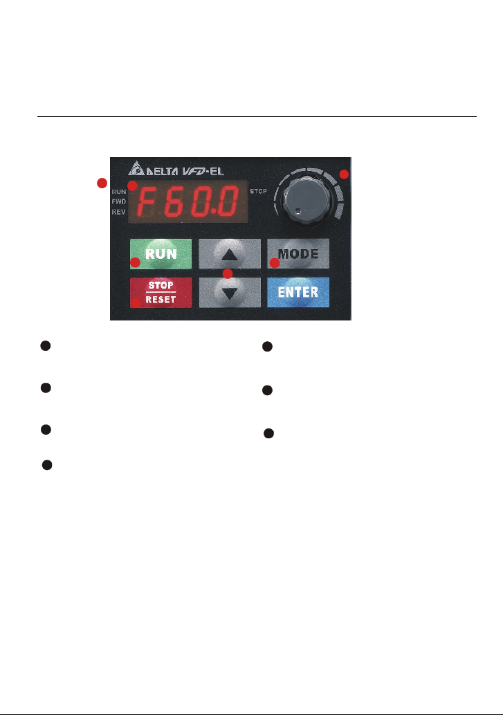
3.1 Description of the Digital Keypad
1
2
4
7
Status Display
1
Display the driver's current status.
2
LED Display
Indicates frequency, voltage, current, user
defined units and etc.
Potentiometer
3
For master Frequency setting.
4
RUN Key
Start AC drive operation.
There are four LEDs on the keypad:
LED STOP: It will light up when the motor is stop.
LED RUN: It will light up when the motor is running.
LED FWD: It will light up when the motor is forward running.
LED REV: It will light up when the motor is reverse running.
5
6
5
UP and DOWN Key
Set the parameter number and changes the
numerical data, such as Master Frequency.
6
MODE
Change between different display mode.
STOP/RESET
7
Stops AC drive operation and reset the drive
after fault occurred.
3
Revision August 2008, 2ELE, V1.02 3-1
Page 39

Chapter 3 Keypad and Start Up|
Display Message Descriptions
Displays the AC drive Master Frequency.
Displays the actual output frequency at terminals U/T1, V/T2, and W/T3.
User defined unit (where U = F x Pr.00.05)
Displays the output current at terminals U/T1, V/T2, and W/T3.
Displays the AC motor drive forward run status.
Displays the AC motor drive reverse run status.
The counter value (C).
Displays the selected parameter.
Displays the actual stored value of the selected parameter.
External Fault.
Display “End” for approximately 1 second if input has been accepted.
After a parameter value has been set, the new value is automatically
stored in memory. To modify an entry, use the
and keys.
Display “Err”, if the input is invalid.
3-2 Revision August 2008, 2ELE, V1.02
Page 40
Chapter 3 Keypad and Start Up|
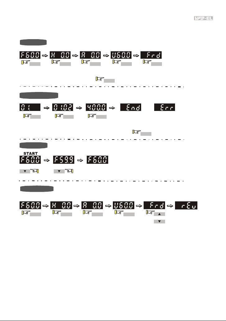
3.2 How to Operate the Digital Keypad
Setting Mode
START
MODE MODE MODE MODE MODE
GO START
In the selection mode, press
NOTE:
Setting parameters
ENTER ENTER ENTER
NOTE
:
In the parameter setting mode, you can press
To s hi f t da ta
MODE
to set the parameters.
Success to
set parameter.
MODE
or
Input data error
to return the selecting mode.
Setting direction
MODE MODE MODE MODE
Revision August 2008, 2ELE, V1.02 3-3
(When operation source is digital keypad)
or
Page 41
Chapter 3 Keypad and Start Up|
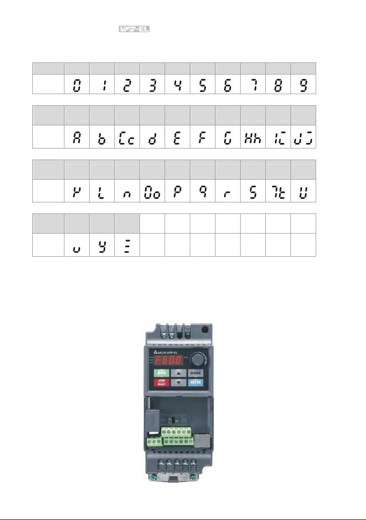
3.3 Reference Table for the 7-segment LED Display of the Digital Keypad
Digit 0 1 2 3 4 5 6 7 8 9
LED
Display
English
alphabet
LED
Display
English
alphabet
LED
Display
English
alphabet
LED
Display
A b Cc d E F G Hh Ii Jj
K L n Oo P q r S Tt U
v Y Z
3.4 Operation Method
The operation method can be set via communication, control terminals and digital keypad.
3-4 Revision August 2008, 2ELE, V1.02
Page 42

Chapter 3 Keypad and Start Up|
AVIA
Operation
Method
Operate from
the
communication
Operate from
external signal
Operate from
the digital
keypad
Frequency Source Operation Command Source
When setting communication by the PC, it needs to use VFD-USB01 or IFD8500
converter to connect to the PC.
Refer to the communication address 2000H and 2101H setting for details.
+24V
Factory setting:
NPN Mode
NPN
Sw1
PNP
Factory setting:
ACI Mode
AVI
Sw2
ACI
FWD/Stop
REV/Stop
Factory
setting
* Don't apply the mains voltage dir ectly
to above terminals.
Multi-step 1
Multi- step 2
Multi-step 3
Multi- step 4
Digital Signal Common
3
2
5K
1
MI1
MI2
MI3
MI4
MI5
MI6
DCM
E
+10V
Power supply
+10V 3mA
Master Frequency
0 to 10V 47 K
CI/AVI
4-20mA/0-10V
ACM
MI3-DCM (Set Pr.04.05=10)
MI4-DCM (Set Pr.04.06=11)
Analog Signal Common
External terminals input:
MI1-DCM (set to FWD/STOP)
MI2-DCM (set to REV/STOP)
E
3.5 Trial Run
You can perform a trial run by using digital keypad with the following steps. by following steps
1. Setting frequency to F5.0 by pressing
2. If you want to change direction from forward running to reverse running: 1. press
key to find FWD. 2. press UP/DOWN key to REV to finish changing direction.
Revision August 2008, 2ELE, V1.02 3-5
.
MODE
Page 43

Chapter 3 Keypad and Start Up|
1. After applying the power, verify that LED
display shows F 60.0Hz.
2. Press
5Hz.
3. Press
you want to change to reverse running, you
should press
decelerate to stop, please press
key.
4. Check following items:
Check if the motor direction of rotation
Check if the motor runs steadily
Check if acceleration and deceleration
If the results of trial run are normal, please start the formal run.
NOTE
1. Stop running immediately if any fault occurs and refer to the troubleshooting guide for
2. Do NOT touch output terminals U/T1, V/T2, W/T3 when power is still applied to R/L1,
3. To avoid damage to components, do not touch them or the circuit boards with metal
key to set frequency to around
key for forward running. And if
. And if you want to
is correct.
without abnormal noise and vibration.
are smooth.
solving the problem.
S/L2, T/L3 even when the AC motor drive has stopped. The DC-link capacitors may still
be charged to hazardous voltage levels, even if the power has been turned off.
objects or your bare hands.
RUN
3-6 Revision August 2008, 2ELE, V1.02
Page 44

Chapter 4 Parameters
The VFD-EL parameters are divided into 11 groups by property for easy setting. In most applications,
the user can finish all parameter settings before start-up without the need for re-adjustment during
operation.
The 11 groups are as follows:
Group 0: User Parameters
Group 1: Basic Parameters
Group 2: Operation Method Parameters
Group 3: Output Function Parameters
Group 4: Input Function Parameters
Group 5: Multi-Step Speed Parameters
Group 6: Protection Parameters
Group 7: Motor Parameters
Group 8: Special Parameters
Group 9: Communication Parameters
Group 10: PID Control Parameters
Revision August 2008, 2ELE, V1.02 4-1
Page 45

Chapter 4 Parameters|
4.1 Summary of Parameter Settings
: The parameter can be set during operation.
Group 0 User Parameters
Parameter Explanation Settings
00.00 Identity Code of the
00.01 Rated Current
00.02 Parameter Reset
00.03
AC motor drive
Display of the AC
motor drive
Start-up Display
Selection
Read-only ##
Read-only #.#
0: Parameter can be read/written
1: All parameters are read only
8: Keypad lock
9: All parameters are reset to factory settings
(50Hz, 230V/400V or 220V/380V depends on
Pr.00.12)
10: All parameters are reset to factory
settings (60Hz, 220V/440V)
0: Display the frequency command value
(Fxxx)
1: Display the actual output frequency (Hxxx)
2: Display the content of user-defined unit
(Uxxx)
3: Multifunction display, see Pr.00.04
4: FWD/REV command
Factory
Setting
0
0
Customer
0: Display the content of user-defined unit
(Uxxx)
1: Display the counter value (c)
2: Display the status of multi-function input
00.04
4-2 Revision August 2008, 2ELE, V1.02
Content of Multi-
function Display
terminals (d)
3: Display DC-BUS voltage (u)
4: Display output voltage (E)
5: Display PID analog feedback signal value
(b) (%)
6: Output power factor angle (n)
0
Page 46

Chapter 4 Parameters|
Parameter Explanation Settings
7: Display output power (P)
Factory
Setting
Customer
8: Display PID setting and feedback signal
9: Display AVI (I) (V)
10: Display ACI (i) (mA)
11: Display the temperature of IGBT (h) (°C)
00.05
User-Defined
Coefficient K
0. 1 to 160.0 1.0
00.06 Software Version Read-only #.##
00.07 Reserved
00.08 Password Input 0 to 9999 0
00.09 Password Set 0 to 9999 0
00.10 Reserved
00.11 Reserved
00.12
00.13
50Hz Base Voltage
Selection
User-defined Value 1
(correspond to max.
0: 230V/400V
1: 220V/380V
0 to 9999
0
0
frequency)
00.14
Position of Decimal
Point of User-
0 to 3
0
defined Value 1
Group 1 Basic Parameters
Factory
Parameter Explanation Settings
01.00
01.01
01.02
Maximum Output
Frequency (Fmax)
Maximum Voltage
Frequency (Fbase)
Maximum Output
Voltage (Vmax)
50.00 to 600.0 Hz 60.00
0.10 to 600.0 Hz 60.00
115V/230V series: 0.1V to 255.0V 220.0
460V series: 0.1V to 510.0V 440.0
Mid-Point Frequency
01.03
(Fmid)
0.10 to 600.0 Hz 1.50
Setting
Customer
Revision August 2008, 2ELE, V1.02 4-3
Page 47

Chapter 4 Parameters|
Parameter Explanation Settings
01.04
01.05
01.06
01.07
01.08
Mid-Point Voltage
(Vmid)
Minimum Output
Frequency (Fmin)
Minimum Output
Voltage (Vmin)
Output Frequency
Upper Limit
Output Frequency
Lower Limit
115V/230V series: 0.1V to 255.0V 10.0
460V series: 0.1V to 510.0V 20.0
0.10 to 600.0 Hz 1.50
115V/230V series: 0.1V to 255.0V 10.0
460V series: 0.1V to 510.0V 20.0
0.1 to 120.0%
0.0 to100.0 %
Factory
Setting
110.0
0.0
01.09 Accel Time 1 0.1 to 600.0 / 0.01 to 600.0 sec 10.0
01.10 Decel Time 1 0.1 to 600.0 / 0.01 to 600.0 sec 10.0
01.11 Accel Time 2 0.1 to 600.0 / 0.01 to 600.0 sec 10.0
01.12 Decel Time 2 0.1 to 600.0 / 0.01 to 600.0 sec 10.0
01.13 Jog Acceleration
Time
01.14 Jog Deceleration
Time
0.1 to 600.0 / 0.01 to 600.0 sec
0.1 to 600.0 / 0.01 to 600.0 sec
1.0
1.0
01.15 Jog Frequency 0.10 Hz to Fmax (Pr.01.00) Hz 6.00
0: Linear Accel/Decel
1: Auto Accel, Linear Decel
2: Linear Accel, Auto Decel
3: Auto Accel/Decel (Set by load)
0
01.16
Auto acceleration /
deceleration (refer
to Accel/Decel time
setting)
4: Auto Accel/Decel (set by Accel/Decel
Time setting)
01.17
01.18
01.19
Acceleration SCurve
Deceleration SCurve
Accel/Decel Time
Unit
0.0 to 10.0 / 0.00 to 10.00 sec 0.0
0.0 to 10.0 / 0.00 to 10.00 sec 0.0
0: Unit: 0.1 sec
1: Unit: 0.01 sec
0
Customer
4-4 Revision August 2008, 2ELE, V1.02
Page 48

Chapter 4 Parameters|
Group 2 Operation Method Parameters
Factory
Parameter Explanation Settings
0: Digital keypad UP/DOWN keys or Multifunction Inputs UP/DOWN. Last used
02.00
02.01
02.02 Stop Method
02.03
02.04
02.05 Line Start Lockout
Source of First
Master Frequency
Command
Source of First
Operation
Command
PWM Carrier
Frequency
Selections
Motor Direction
Control
frequency saved.
1: 0 to +10V from AVI
2: 4 to 20mA from ACI
3: RS-485 (RJ-45) communication
4: Digital keypad potentiometer
0: Digital keypad
1: External terminals. Keypad STOP/RESET
enabled.
2: External terminals. Keypad STOP/RESET
disabled.
3: RS-485 (RJ-45) communication. Keypad
STOP/RESET enabled.
4: RS-485 (RJ-45) communication. Keypad
STOP/RESET disabled.
0: STOP: ramp to stop; E.F.: coast to stop
1: STOP: coast to stop; E.F.: coast to stop
2: STOP: ramp to stop; E.F.: ramp to stop
3: STOP: coast to stop; E.F.: ramp to stop
2 to 12kHz 8
0: Enable forward/reverse operation
1: Disable reverse operation
2: Disabled forward operation
0: Disable. Operation status is not changed
even if operation command source Pr.02.01
is changed.
1: Enable. Operation status is not changed
even if operation command source Pr.02.01
is changed.
2: Disable. Operation status will change if
operation command source Pr.02.01 is
changed.
Setting
1
1
0
0
1
Customer
Revision August 2008, 2ELE, V1.02 4-5
Page 49

Chapter 4 Parameters|
Parameter Explanation Settings
3: Enable. Operation status will change if
operation command source Pr.02.01 is
changed.
0: Decelerate to 0 Hz
02.06
Loss of ACI Signal
(4-20mA)
1: Coast to stop and display “AErr”
2: Continue operation by last frequency
command
0: by UP/DOWN Key
02.07 Up/Down Mode
1: Based on accel/decel time
2: Constant speed (Pr.02.08)
3: Pulse input unit (Pr.02.08)
Accel/Decel Rate of
Change of
02.08
UP/DOWN
0.01~10.00 Hz 0.01
Operation with
Constant Speed
0: Digital keypad UP/DOWN keys or Multifunction Inputs UP/DOWN. Last used
frequency saved.
1: 0 to +10V from AVI
2: 4 to 20mA from ACI
02.09
Source of Second
Frequency
Command
3: RS-485 (RJ-45) communication
4: Digital keypad potentiometer
0: First Master Frequency Command
1: First Master Frequency Command+
Second Master Frequency Command
2: First Master Frequency Command Second Master Frequency Command
0.00 to 600.0Hz
0.00 to 600.0Hz
02.10
02.11
02.12
Combination of the
First and Second
Master Frequency
Command
Keypad Frequency
Command
Communication
Frequency
Command
0: Save Keypad & Communication
Frequency
1: Save Keypad Frequency only
02.13
The Selections for
Saving Keypad or
Communication
Frequency
Command
2: Save Communication Frequency only
Factory
Setting
1
0
0
0
60.00
60.00
0
Customer
4-6 Revision August 2008, 2ELE, V1.02
Page 50

Chapter 4 Parameters|
Parameter Explanation Settings
0: by Current Freq Command
1: by Zero Freq Command
2: by Frequency Display at Stop
02.14
Initial Frequency
Selection (for
keypad & RS485)
Initial Frequency
02.15
Setpoint (for keypad
0.00 ~ 600.0Hz 60.00
Factory
Setting
0
Customer
& RS485)
02.16
Display the Master
Freq Command
Source
Read Only
Bit0=1: by First Freq Source (Pr.02.00)
Bit1=1: by Second Freq Source (Pr.02.09)
##
Bit2=1: by Multi-input function
02.17
Display the
Operation
Command Source
Read Only
Bit0=1: by Digital Keypad
Bit1=1: by RS485 communication
Bit2=1: by External Terminal 2/3 wire mode
##
Bit3=1: by Multi-input function
02.18
02.19
User-defined Value
2 Setting
User-defined Value
2
0 to Pr.00.13 0
0 to 9999 ##
Group 3 Output Function Parameters
Factory
Parameter Explanation Settings
03.00 Multi-function
Output Relay (RA1,
RB1, RC1)
0: No function
1: AC drive operational
Customer
Setting
8
2: Master frequency attained
3: Zero speed
4: Over torque detection
5: Base-Block (B.B.) indication
6: Low-voltage indication
7: Operation mode indication
8: Fault indication
9: Desired frequency attained
10: Terminal count value attained
Revision August 2008, 2ELE, V1.02 4-7
Page 51

Chapter 4 Parameters|
Parameter Explanation Settings
Factory
Setting
11: Preliminary count value attained
12: Over Voltage Stall supervision
13: Over Current Stall supervision
14: Heat sink overheat warning
15: Over Voltage supervision
16: PID supervision
17: Forward command
18: Reverse command
19: Zero speed output signal
20: Warning(FbE,Cexx, AoL2, AUE, SAvE)
21: Brake control (Desired frequency
attained)
22: AC motor drive ready
03.01 Reserved
03.02 Desired Frequency
0.00 to 600.0Hz 0.00
Attained
03.03
Analog Output
Signal Selection
(AFM)
0: Analog frequency meter
1: Analog current meter
0
03.04 Analog Output Gain 1 to 200% 100
03.05 Terminal Count
0 to 9999 0
Value
03.06
03.07
Preliminary Count
Value
EF Active When
Terminal Count
Value Attained
0 to 9999 0
0: Terminal count value attained, no EF
display
1: Terminal count value attained, EF active
0
0: Fan always ON
1: 1 minute after AC motor drive stops, fan
will be OFF
03.08 Fan Control
2: Fan ON when AC motor drive runs, fan
0
OFF when AC motor drive stops
3: Fan ON when preliminary heatsink
temperature attained
03.09 Reserved
Customer
4-8 Revision August 2008, 2ELE, V1.02
Page 52

Chapter 4 Parameters|
Parameter Explanation Settings
Factory
Setting
Customer
03.10 Reserved
03.11
03.12
03.13
Brake Release
Frequency
Brake Engage
Frequency
Display the Status of
Relay
0.00 to 20.00Hz 0.00
0.00 to 20.00Hz 0.00
Read only ##
Group 4 Input Function Parameters
Factory
Parameter Explanation Settings
04.00
Keypad
Potentiometer Bias
0.0 to 100.0 % 0.0
Setting
Customer
04.01
Keypad
Potentiometer Bias
Polarity
04.02
Keypad
Potentiometer Gain
Keypad
04.03
Potentiometer
Negative Bias,
Reverse Motion
Enable/Disable
04.04 2-wire/3-wire
Operation Control
Modes
04.05 Multi-function Input
Terminal (MI3)
04.06 Multi-function Input
Terminal (MI4)
04.07 Multi-function Input
Terminal (MI5)
0: Positive bias
1: Negative bias
00
0.1 to 200.0 % 100.0
0: No negative bias command
0
1: Negative bias: REV motion enabled
0: 2-wire: FWD/STOP, REV/STOP
1: 2-wire: FWD/REV, RUN/STOP
0
2: 3-wire operation
0: No function 1
1: Multi-Step speed command 1
2: Multi-Step speed command 2
3: Multi-Step speed command 3 2
4: Multi-Step speed command 4
5: External reset
6: Accel/Decel inhibit 3
7: Accel/Decel time selection command
8: Jog Operation
Revision August 2008, 2ELE, V1.02 4-9
Page 53

Chapter 4 Parameters|
Parameter Explanation Settings
04.08 Multi-function Input
Terminal (MI6)
9: External base block 4
10: Up: Increment master frequency
11: Down: Decrement master frequency
12: Counter Trigger Signal
13: Counter reset
14: E.F. External Fault Input
15: PID function disabled
16: Output shutoff stop
17: Parameter lock enable
18: Operation command selection (external
terminals)
19: Operation command selection(keypad)
20: Operation command
selection(communication)
21: FWD/REV command
22: Source of second frequency command
Bit0:MI1
Bit1:MI2
Bit2:MI3
04.09
Multi-function Input
Contact Selection
Bit3:MI4
Bit4:MI5
Bit5:MI6
0:N.O., 1:N.C.
P.S.:MI1 to MI3 will be invalid when it is 3wire control.
Digital Terminal
04.10
Input Debouncing
1 to 20 (*2ms) 1
Time
Min AVI Voltage 0.0 to 10.0V
04.11
Min AVI Frequency
04.12
Max AVI Voltage 0.0 to 10.0V
04.13
Max AVI Frequency 0.0 to 100.0%
04.14
0.0 to 100.0%
Factory
Customer
Setting
0
0.0
0.0
10.0
100.0
4-10 Revision August 2008, 2ELE, V1.02
Page 54

Chapter 4 Parameters|
Parameter Explanation Settings
04.15
04.16
04.17
04.18
Min ACI Current 0.0 to 20.0mA
Min ACI Frequency
0.0 to 100.0%
Max ACI Current 0.0 to 20.0mA
Max ACI Frequency 0.0 to 100.0%
Factory
Customer
Setting
4.0
0.0
20.0
100.0
04.19
Reserved
|
04.25
Read only.
Bit0: MI1 Status
Bit1: MI2 Status
Bit2: MI3 Status
Bit3: MI4 Status
##
04.26
Display the Status
of Multi-function
Input Terminal
Bit4: MI5 Status
Bit5: MI6 Status
04.27
Internal/External
Multi-function Input
0~4095
0
Terminals Selection
04.28
Internal Terminal
Status
0~4095
0
Group 5 Multi-Step Speed Parameters
Factory
Parameter Explanation Settings
05.00 1st Step Speed
0.00 to 600.0 Hz 0.00
Setting
Customer
Frequency
05.01 2nd Step Speed
0.00 to 600.0 Hz 0.00
Frequency
05.02 3rd Step Speed
0.00 to 600.0 Hz 0.00
Frequency
05.03 4th Step Speed
0.00 to 600.0 Hz 0.00
Frequency
05.04 5th Step Speed
0.00 to 600.0 Hz 0.00
Frequency
Revision August 2008, 2ELE, V1.02 4-11
Page 55

Chapter 4 Parameters|
r
Parameter Explanation Settings
05.05 6th Step Speed
0.00 to 600.0 Hz 0.00
Frequency
05.06 7th Step Speed
0.00 to 600.0 Hz 0.00
Frequency
05.07 8th Step Speed
0.00 to 600.0 Hz 0.00
Frequency
05.08 9th Step Speed
0.00 to 600.0 Hz 0.00
Frequency
05.09 10th Step Speed
0.00 to 600.0 Hz 0.00
Frequency
05.10 11th Step Speed
0.00 to 600.0 Hz 0.00
Frequency
05.11 12th Step Speed
0.00 to 600.0 Hz 0.00
Frequency
05.12 13th Step Speed
0.00 to 600.0 Hz 0.00
Frequency
05.13 14th Step Speed
0.00 to 600.0 Hz 0.00
Frequency
05.14 15th Step Speed
0.00 to 600.0 Hz 0.00
Frequency
Group 6 Protection Parameters
Parameter Explanation Settings
115/230V series: 330.0V to 410.0V 390.0V
06.00
Over-Voltage Stall
Prevention
460V series: 660.0V to 820.0V 780.0V
0.0: Disable over-voltage stall prevention
06.01
06.02
Over-Current Stall
Prevention during
Accel
Over-Current Stall
Prevention during
Operation
0:Disable
20 to 250%
0:Disable
20 to 250%
0: Disabled 06.03 Over-Torque
Detection Mode
(OL2)
1: Enabled during constant speed operation.
After the over-torque is detected, keep
running until OL1 or OL occurs.
Factory
Customer
Setting
Factory
Custome
Setting
170
170
0
4-12 Revision August 2008, 2ELE, V1.02
Page 56

Chapter 4 Parameters|
r
Parameter Explanation Settings
Factory
Setting
Custome
2: Enabled during constant speed operation.
After the over-torque is detected, stop
running.
3: Enabled during accel. After the over-torque
is detected, keep running until OL1 or OL
occurs.
06.04
06.05
06.06
Over-Torque
Detection Level
Over-Torque
Detection Time
Electronic Thermal
Overload Relay
Selection
4: Enabled during accel. After the over-torque
is detected, stop running.
10 to 200% 150
0.1 to 60.0 sec 0.1
0: Standard motor (self cooled by fan)
1: Special motor (forced external cooling)
2
2: Disabled
06.07
Electronic Thermal
Characteristic
30 to 600 sec 60
0: No fault
0
1: Over current (oc)
06.08
Present Fault
Record
2: Over voltage (ov)
3: IGBT Overheat (oH1)
4: Reserved
06.09 Second Most
Recent Fault Record
5: Overload (oL)
6: Overload1 (oL1)
7: Motor over load (oL2)
8: External fault (EF)
9: Current exceeds 2 times rated current
during accel.(ocA)
10: Current exceeds 2 times rated current
during decel.(ocd)
11: Current exceeds 2 times rated current
during steady state operation (ocn)
12: Ground fault (GFF)
13: Reserved
Revision August 2008, 2ELE, V1.02 4-13
Page 57

Chapter 4 Parameters|
r
r
Parameter Explanation Settings
Factory
Setting
14: Phase-Loss (PHL)
15: Reserved
16: Auto Acel/Decel failure (CFA)
06.10
Third Most Recent
Fault Record
17: SW/Password protection (codE)
18: Power Board CPU WRITE failure (cF1.0)
19: Power Board CPU READ failure (cF2.0)
20: CC, OC Hardware protection failure
(HPF1)
06.11
Fourth Most Recent
Fault Record
21: OV Hardware protection failure (HPF2)
22: GFF Hardware protection failure (HPF3)
23: OC Hardware protection failure (HPF4)
24: U-phase error (cF3.0)
06.12
Fifth Most Recent
Fault Record
25: V-phase error (cF3.1)
26: W-phase error (cF3.2)
27: DCBUS error (cF3.3)
28: IGBT Overheat (cF3.4)
29: Reserved
30: Reserved
31: Reserved
32: ACI signal error (AErr)
33: Reserved
34: Motor PTC overheat protection (PtC1)
35-40: Reserved
Custome
Group 7 Motor Parameters
Factory
Parameter Explanation Settings
Setting
Custome
07.00 Motor Rated Current 30 %FLA to 120% FLA FLA
07.01
4-14 Revision August 2008, 2ELE, V1.02
Motor No-Load
Current
0%FLA to 99% FLA 0.4*FLA
Page 58

Chapter 4 Parameters|
r
r
Factory
Parameter Explanation Settings
07.02
07.03 Slip Compensation 0.00 to 10.00 0.00
07.04
07.09
07.10
07.11
07.12
07.13
07.14
07.15
07.16
07.17
Torque
Compensation
Reserved
|
Accumulative Motor
Operation Time
(Min.)
Accumulative Motor
Operation Time
(Day)
Motor PTC
Overheat Protection
Input Debouncing
Time of the PTC
Protection
Motor PTC
Overheat Protection
Level
Motor PTC
Overheat Warning
Level
Motor PTC
Overheat Reset
Delta Level
Treatment of the
Motor PTC
Overheat
0.0 to 10.0 0.0
0 to 1439 Min. 0
0 to 65535 Day 0
0: Disable
1: Enable
0~9999(*2ms) 100
0.1~10.0V 2.4
0.1~10.0V 1.2
0.1~5.0V 0.6
0: Warn and RAMP to stop
1: Warn and COAST to stop
2: Warn and keep running
Setting
0
0
Custome
Group 8 Special Parameters
Factory
Parameter Explanation Settings
08.00
08.01
Revision August 2008, 2ELE, V1.02 4-15
DC Brake Current
Level
DC Brake Time
during Start-Up
0 to 100% 0
0.0 to 60.0 sec 0.0
Setting
Custome
Page 59

Chapter 4 Parameters|
r
Parameter Explanation Settings
08.02
08.03
DC Brake Time
during Stopping
Start-Point for DC
Brake
0.0 to 60.0 sec 0.0
0.00 to 600.0Hz 0.00
0: Operation stops after momentary power
loss
1: Operation continues after momentary
power loss, speed search starts with the
Master Frequency reference value
08.04
Momentary Power
Loss Operation
Selection
2: Operation continues after momentary
power loss, speed search starts with the
minimum frequency
08.05
Maximum Allowable
Power Loss Time
0.1 to 5.0 sec 2.0
0: Disable speed search
08.06
Base-block Speed
Search
1: Speed search starts with last frequency
command
2: Starts with minimum output frequency
08.07
08.08
08.09
08.10
08.11
08.12
08.13
08.14
B.B. Time for Speed
Search
Current Limit for
Speed Search
Skip Frequency 1
Upper Limit
Skip Frequency 1
Lower Limit
Skip Frequency 2
Upper Limit
Skip Frequency 2
Lower Limit
Skip Frequency 3
Upper Limit
Skip Frequency 3
Lower Limit
08.15 Auto Restart After
0.1 to 5.0 sec 0.5
30 to 200% 150
0.00 to 600.0 Hz 0.00
0.00 to 600.0 Hz 0.00
0.00 to 600.0 Hz 0.00
0.00 to 600.0 Hz 0.00
0.00 to 600.0 Hz 0.00
0.00 to 600.0 Hz 0.00
0 to 10 (0=disable) 0
Fault
08.16
Auto Reset Time at
Restart after Fault
0.1 to 6000 sec
Factory
Setting
0
1
60.0
Custome
4-16 Revision August 2008, 2ELE, V1.02
Page 60

Chapter 4 Parameters|
r
r
Factory
Parameter Explanation Settings
08.17 Auto Energy Saving
0: Disable
1: Enable
0: AVR function enable
08.18 AVR Function
1: AVR function disable
2: AVR function disable for decel.
Setting
0
0
Custome
3: AVR function disable for stop
08.19 Reserved
08.20
Compensation
Coefficient for Motor
0.0~5.0
Instability
Group 9 Communication Parameters
Parameter Explanation Settings
09.00
Communication
Address
1 to 254 1
0: Baud rate 4800bps
09.01 Transmission Speed
1: Baud rate 9600bps
2: Baud rate 19200bps
3: Baud rate 38400bps
0: Warn and keep operating
09.02
Transmission Fault
Treatment
1: Warn and ramp to stop
2: Warn and coast to stop
3: No warning and keep operating
09.03 Time-out Detection
09.04 Communication
Protocol
0.1 ~ 120.0 seconds
0.0: Disable
0: 7,N,2 (Modbus, ASCII)
1: 7,E,1 (Modbus, ASCII)
2: 7,O,1 (Modbus, ASCII)
3: 8,N,2 (Modbus, RTU)
0.0
Factory
Custome
Setting
1
3
0.0
0
Revision August 2008, 2ELE, V1.02 4-17
Page 61

Chapter 4 Parameters|
r
r
Parameter Explanation Settings
4: 8,E,1 (Modbus, RTU)
5: 8,O,1 (Modbus, RTU)
6: 8,N,1 (Modbus, RTU)
7: 8,E,2 (Modbus, RTU)
8: 8,O,2 (Modbus, RTU)
9: 7,N,1 (Modbus, ASCII)
10: 7,E,2 (Modbus, ASCII)
11: 7,O,2 (Modbus, ASCII)
09.05 Reserved
09.06 Reserved
09.07
Response Delay
Time
0 ~ 200 (unit: 2ms)
Group 10 PID Control Parameters
Parameter Explanation Settings
0: Disable PID operation
1: Keypad (based on Pr.02.00)
10.00
PID Set Point
Selection
2: 0 to +10V from AVI
3: 4 to 20mA from ACI
4: PID set point (Pr.10.11)
0: Positive PID feedback from external
terminal AVI (0 ~ +10VDC)
1: Negative PID feedback from external
10.01
Input Terminal for
PID Feedback
terminal AVI (0 ~ +10VDC)
2: Positive PID feedback from external
terminal ACI (4 ~ 20mA)
3: Negative PID feedback from external
terminal ACI (4 ~ 20mA)
10.02
Proportional Gain
(P)
10.03 Integral Time (I)
0.0 to 10.0 1.0
0.00 to 100.0 sec (0.00=disable)
Factory
Custome
Setting
1
Factory
Custome
Setting
0
0
1.00
4-18 Revision August 2008, 2ELE, V1.02
Page 62

Chapter 4 Parameters|
r
Parameter Explanation Settings
10.04
10.05
10.06
10.07
Derivative Control
(D)
Upper Bound for
Integral Control
Primary Delay Filter
Time
PID Output Freq
Limit
0.00 to 1.00 sec
0 to 100% 100
0.0 to 2.5 sec 0.0
0 to 110% 100
PID Feedback
10.08
Signal Detection
0.0 to 3600 sec (0.0 disable) 60.0
Factory
Setting
0.00
Custome
Time
10.09
10.10
10.11
Treatment of the
Erroneous PID
Feedback Signals
Gain Over the PID
Detection Value
Source of PID Set
point
0: Warn and RAMP to stop
1: Warn and COAST to stop
0
2: Warn and keep operation
0.0 to 10.0 1.0
0.00 to 600.0Hz
0.00
10.12 PID Feedback Level 1.0 to 50.0% 10.0
10.13
10.14
Detection Time of
PID Feedback
Sleep/Wake Up
Detection Time
0.1 to 300.0 sec 5.0
0.0 to 6550 sec 0.0
10.15 Sleep Frequency 0.00 to 600.0 Hz 0.00
10.16 Wakeup Frequency 0.00 to 600.0 Hz 0.00
10.17
Minimum PID
Output Frequency
Selection
0: By PID control
1: By minimum output frequency (Pr.01.05)
0
PID Control
10.18
Detection Signal
1.0 to 99.9 99.9
Reference
10.19
PID Calculation
Mode Selection
0: Series mode
1: Parallel mode
0
Revision August 2008, 2ELE, V1.02 4-19
Page 63

Chapter 4 Parameters|
r
Parameter Explanation Settings
0: Keep operating
10.20
Treatment of the
Erroneous PID
Feedback Level
1: Coast to stop
2: Ramp to stop
3: Ramp to stop and restart after time set in
Pr.10.21
Restart Delay Time
10.21
after Erroneous PID
1 to 9999 sec 60
Deviation Level
10.22
Set Point Deviation
Level
0 to 100% 0
Detection Time of
10.23
Set Point Deviation
0 to 9999 sec 10
Level
10.24
10.25
Offset Level of
Liquid Leakage
Liquid Leakage
Change Detection
0 to 50% 0
0 to 100% (0: disable) 0
Time Setting for
10.26
Liquid Leakage
0.1 to 10.0 sec (0: disable) 0.5
Change
10.27
|
Reserved
10.33
Factory
Setting
0
Custome
4-20 Revision August 2008, 2ELE, V1.02
Page 64

Chapter 4 Parameters|
4.2 Parameter Settings for Applications
Speed Search
Applications Purpose Functions
Windmill, winding
machine, fan and all
inertia loads
Restart freerunning motor
Before the free-running motor is
completely stopped, it can be restarted
without detection of motor speed. The
AC motor drive will auto search motor
speed and will accelerate when its
speed is the same as the motor speed.
DC Brake before Running
Applications Purpose Functions
When e.g. windmills,
fans and pumps rotate
freely by wind or flow
Keep the freerunning motor at
standstill.
If the running direction of the freerunning motor is not steady, please
execute DC brake before start-up.
without applying power
Energy Saving
Applications Purpose Functions
Punching machines
fans, pumps and
precision machinery
Energy saving and
less vibrations
Energy saving when the AC motor
drive runs at constant speed, yet full
power acceleration and deceleration
For precision machinery it also helps
to lower vibrations.
Multi-step Operation
Applications Purpose Functions
Conveying machinery
Cyclic operation by
multi-step speeds.
To control 15-step speeds and duration
by simple contact signals.
Switching acceleration and deceleration times
Applications Purpose Functions
Auto turntable for
conveying machinery
Switching
acceleration and
deceleration times
by external signal
When an AC motor drive drives two or
more motors, it can reach high-speed
but still start and stop smoothly.
Related
Parameters
08.04~08.08
Related
Parameters
08.00
08.01
Related
Parameters
08.17
Related
Parameters
04.05~04.08
05.00~05.14
Related
Parameters
01.09~01.12
04.05~04.08
Revision August 2008, 2ELE, V1.02 4-21
Page 65
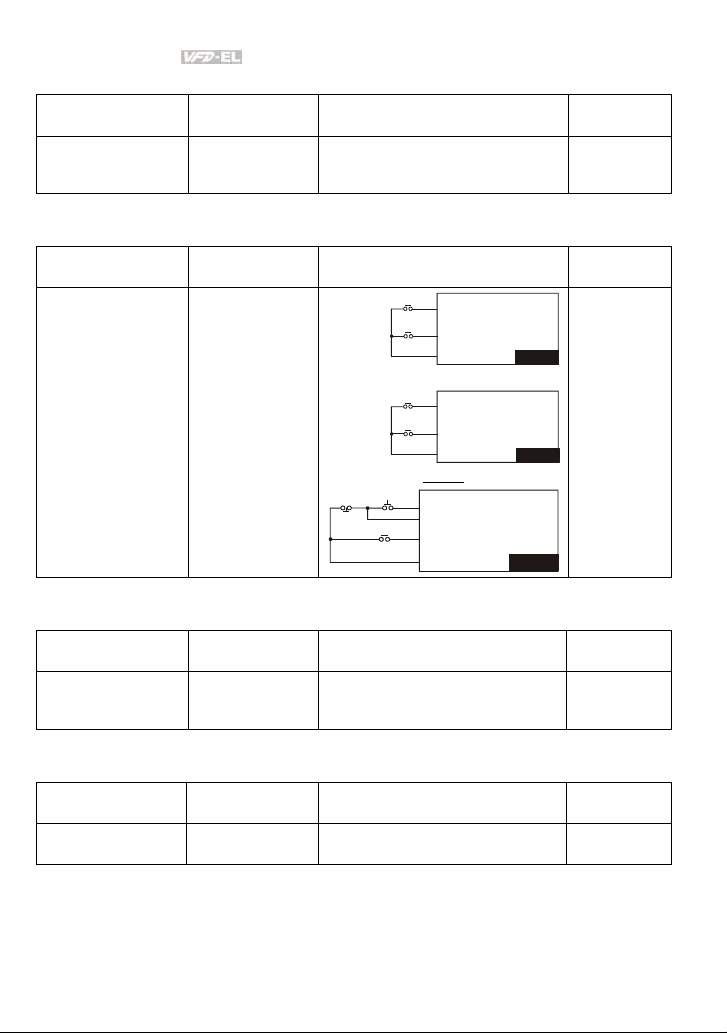
Chapter 4 Parameters|
V
V
P
V
Overheat Warning
Applications Purpose Functions
When AC motor drive overheats, it
Air conditioner Safety measure
uses a thermal sensor to have
overheat warning.
Two-wire/three-wire
Applications Purpose Functions
FWD/STOP
REV/STOP
MI1:("OPEN":STOP)
("CLOSE":FWD)
MI2:("OPEN": STOP)
("CLOSE": REV)
DCM
MI1:("OPEN":STOP)
("CLOSE":RUN)
MI2:("OPEN": FWD)
("CLOSE": REV)
DCM
General application
To run, stop,
forward and
reverse by external
terminals
RUN/STOP
FWD/REV
3-wire
STO
RUN
MI1 ("CLOSE":R UN):
MI3:("OPEN":STOP)
MI2:("OPEN": FWD)
REV/FWD
("CLOSE": REV)
DCM
Operation Command
Applications Purpose Functions
General application
Selecting the
source of control
signal
Selection of AC motor drive control by
external terminals, digital keypad or
RS485.
Frequency Hold
Applications Purpose Functions
General application
Acceleration/
deceleration pause
Hold output frequency during
Acceleration/deceleration
FD-EL
FD-EL
FD-EL
Related
Parameters
03.00
04.05~04.08
Related
Parameters
02.00
02.01
02.09
04.04
Related
Parameters
02.01
04.05~04.08
Related
Parameters
04.05~04.08
4-22 Revision August 2008, 2ELE, V1.02
Page 66

Chapter 4 Parameters|
Auto Restart after Fault
Applications Purpose Functions
Air conditioners,
remote pumps
For continuous and
reliable operation
without operator
intervention
The AC motor drive can be
restarted/reset automatically up to 10
times after a fault occurs.
Related
Parameters
08.15~08.16
Emergency Stop by DC Brake
Applications Purpose Functions
AC motor drive can use DC brake for
High-speed rotors
Emergency stop
without brake
resistor
emergency stop when quick stop is
needed without brake resistor. When
used often, take motor cooling into
Related
Parameters
08.00
08.02
08.03
consideration.
Over-torque Setting
Applications Purpose Functions
The over-torque detection level can be
set. Once OC stall, OV stall and overtorque occurs, the output frequency
will be adjusted automatically. It is
suitable for machines like fans and
pumps that require continuous
Pumps, fans and
extruders
To protect
machines and to
have continuous/
reliable operation
Related
Parameters
06.00~06.05
operation.
Upper/Lower Limit Frequency
Applications Purpose Functions
When user cannot provide
upper/lower limit, gain or bias from
external signal, it can be set
individually in AC motor drive.
Pump and fan
Control the motor
speed within
upper/lower limit
Related
Parameters
01.07
01.08
Skip Frequency Setting
Applications Purpose Functions
The AC motor drive cannot run at
Pumps and fans
To prevent
machine vibrations
constant speed in the skip frequency
range. Three skip frequency ranges
Related
Parameters
08.09~08.14
can be set.
Revision August 2008, 2ELE, V1.02 4-23
Page 67

Chapter 4 Parameters|
Carrier Frequency Setting
Applications Purpose Functions
The carrier frequency can be
General application Low noise
increased when required to reduce
motor noise.
Keep Running when Frequency Command is Lost
Applications Purpose Functions
When the frequency command is lost
Air conditioners
For continuous
operation
by system malfunction, the AC motor
drive can still run. Suitable for
intelligent air conditioners.
Output Signal during Running
Applications Purpose Functions
Signal available to stop braking (brake
General application
Provide a signal for
running status
release) when the AC motor drive is
running. (This signal will disappear
when the AC motor drive is freerunning.)
Output Signal in Zero Speed
Applications Purpose Functions
When the output frequency is lower
General application
Provide a signal for
running status
than the min. output frequency, a
signal is given for external system or
control wiring.
Output Signal at Desired Frequency
Applications Purpose Functions
When the output frequency is at the
General application
Provide a signal for
running status
desired frequency (by frequency
command), a signal is given for
external system or control wiring
(frequency attained).
Related
Parameters
02.03
Related
Parameters
02.06
Related
Parameters
03.00
Related
Parameters
03.00
Related
Parameters
03.00
4-24 Revision August 2008, 2ELE, V1.02
Page 68

Chapter 4 Parameters|
Output Signal for Base Block
Applications Purpose Functions
General application
Provide a signal for
running status
When executing Base Block, a signal
is given for external system or control
wiring.
Related
Parameters
03.00
Overheat Warning for Heat Sink
Applications Purpose Functions
When heat sink is overheated, it will
General application For safety
send a signal for external system or
Related
Parameters
03.00
control wiring.
Multi-function Analog Output
Applications Purpose Functions
The value of frequency, output
General application
Display running
status
current/voltage can be read by
connecting a frequency meter or
Related
Parameters
03.06
voltage/current meter.
Revision August 2008, 2ELE, V1.02 4-25
Page 69
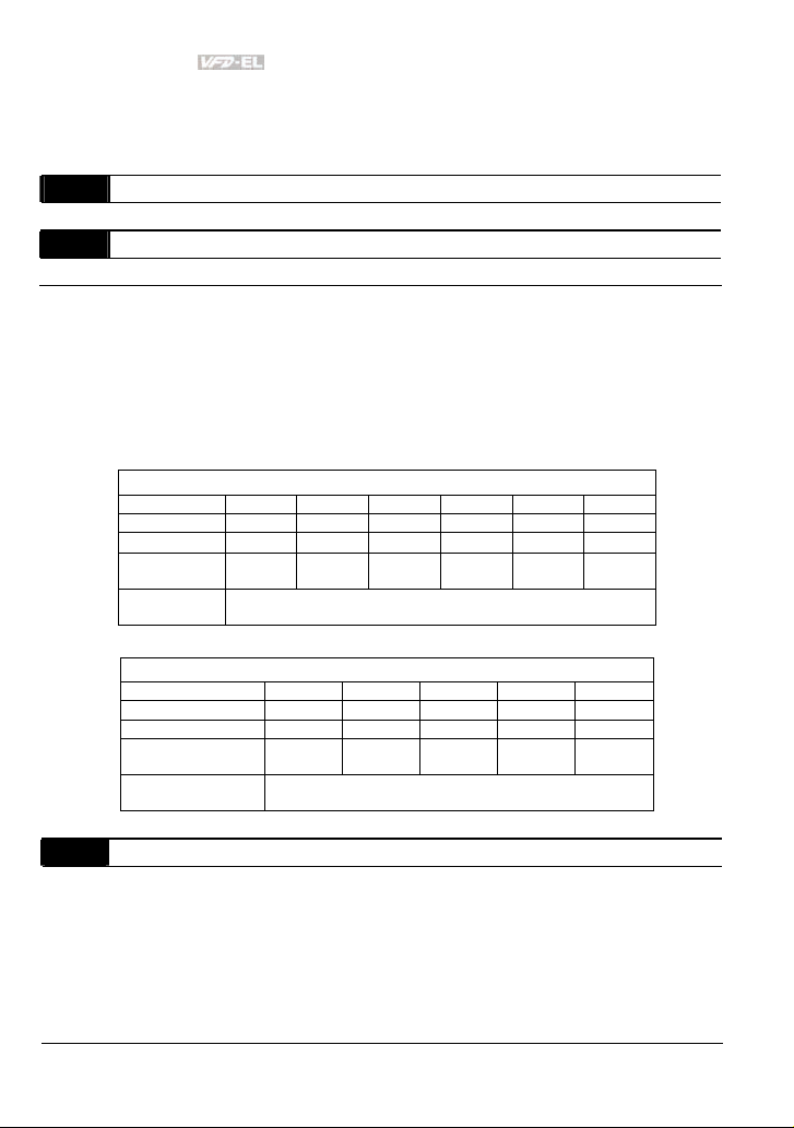
Chapter 4 Parameters|
4.3 Description of Parameter Settings
Group 0: User Parameters This parameter can be set during operation.
00.00 Identity Code of the AC Motor Drive
Settings Read Only Factory setting: ##
00.01 Rated Current Display of the AC Motor Drive
Settings Read Only Factory setting: #.#
Pr. 00.00 displays the identity code of the AC motor drive. The capacity, rated current, rated
voltage and the max. carrier frequency relate to the identity code. Users can use the following
table to check how the rated current, rated voltage and max. carrier frequency of the AC motor
drive correspond to the identity code.
Pr.00.01 displays the rated current of the AC motor drive. By reading this parameter the user
can check if the AC motor drive is correct.
115V/230V Series
kW 0.2 0.4 0.75 1.5 2.2 3.7
HP 0.25 0.5 1.0 2.0 3.0 5.0
Pr.00-00
Rated Output
Current (A)
Max. Carrier
Frequency
kW 0.4 0.75 1.5 2.2 3.7
HP 0.5 1.0 2.0 3.0 5.0
Pr.00-00 3 5 7 9 11
Rated Output
Current (A)
Max. Carrier
Frequency
00.02
Parameter Reset
Factory Setting: 0
Settings 0 Parameter can be read/written
1 All parameters are read-only
8 Keypad lock
9 All parameters are reset to factory settings (50Hz, 230V/400V or
10 All parameters are reset to factory settings (60Hz, 115V/220V/440V)
0 2 4 6 8 10
1.6 2.5 4.2 7.5 11.0 17.0
12kHz
460V Series
1.5 2.5 4.2 5.5 8.2
12kHz
220V/380V depends on Pr.00.12)
4-26 Revision August 2008, 2ELE, V1.02
Page 70
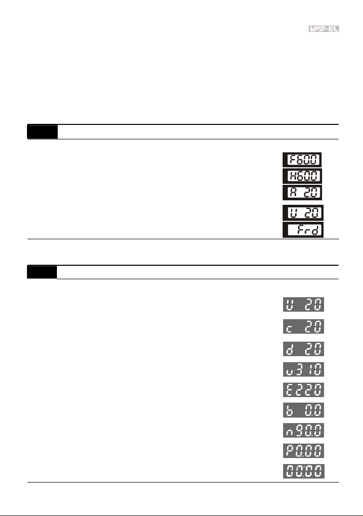
Chapter 4 Parameters|
This parameter allows the user to reset all parameters to the factory settings except the fault
records (Pr.06.08 ~ Pr.06.12).
50Hz: Pr.01.00 and Pr.01.01 are set to 50Hz and Pr.01.02 will be set by Pr.00.12.
60Hz: Pr.01.00 and Pr.01.01 are set to 60Hz and Pr.01.02 is set to 115V, 230V or 460V.
When Pr.00.02=1, all parameters are read-only. To write all parameters, set Pr.00.02=0.
Start-up Display Selection
00.03
Factory Setting: 0
Settings 0 Display the frequency command value (Fxxx)
1 Display the actual output frequency (Hxxx)
2 Display the output current in A supplied to the motor
3 Display the content of user-defined unit (Uxxx)
4 FWD/REV command
This parameter determines the start-up display page after power is applied to the drive.
00.04 Content of Multi-function Display
Settings 0 Display the content of user-defined unit (Uxxx)
1
2 Display status of multi-input terminals (d)
3
4
5 Display PID analog feedback signal value in %
6
7
8 Display PID setting and feedback signal.
(Axxx)
Display the counter value which counts the number of
pulses on TRG terminal
Display the actual DC BUS voltage in VDC of the AC
motor drive
Display the output voltage in VAC of terminals U/T1,
V/T2, W/T3 to the motor.
Display the power factor angle in º of terminals U/T1,
V/T2, W/T3 to the motor
Display the output power in kW of terminals U, V and W
to the motor.
Factory Setting: 0
Revision August 2008, 2ELE, V1.02 4-27
Page 71

Chapter 4 Parameters|
00.04 Content of Multi-function Display
9 Display the signal of AVI analog input terminal (V).
10 Display the signal of ACI analog input terminal (mA).
11
Display the temperature of IGBT (h) in °C
When Pr00.03 is set to 03, the display is according to the setting of Pr00.04.
00.05 User Defined Coefficient K Unit: 0. 1
Settings 0. 1 to d 160.0 Factory Setting: 1.0
The coefficient K determines the multiplying factor for the user-defined unit.
The display value is calculated as follows:
U (User-defined unit) = Actual output frequency * K (Pr.00.05)
Example:
A conveyor belt runs at 13.6m/s at motor speed 60Hz.
K = 13.6/60 = 0.22 (0.226667 rounded to 1 decimal), therefore Pr.00.05=0.2
With Frequency command 35Hz, display shows U and 35*0.2=7.0m/s.
(To increase accuracy, use K=2.2 or K=22.7 and disregard decimal point.)
00.06 Software Version
Settings Read Only
Display #.##
00.07
Reserved
00.08
Password Input
Unit: 1
Settings 0 to 9999 Factory Setting: 0
Display 0~2 (times of wrong password)
The function of this parameter is to input the password that is set in Pr.00.09. Input the correct
password here to enable changing parameters. You are limited to a maximum of 3 attempts.
After 3 consecutive failed attempts, a blinking “codE” will show up to force the user to restart
the AC motor drive in order to try again to input the correct password.
4-28 Revision August 2008, 2ELE, V1.02
Page 72
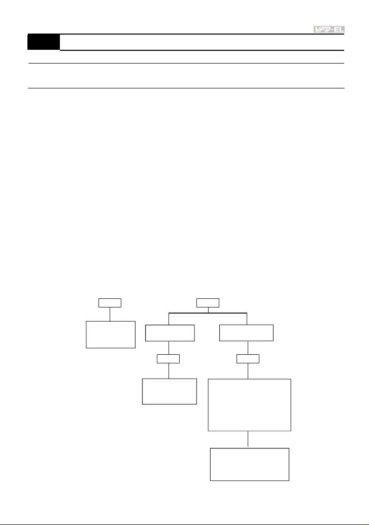
Chapter 4 Parameters|
g
Password Set Unit: 1
00.09
Settings 0 to 9999 Factory Setting: 0
Display 0 No password set or successful input in Pr. 00.08
1 Password has been set
To set a password to protect your parameter settings.
If the display shows 0, no password is set or password has been correctly entered in Pr.00.08.
All parameters can then be changed, including Pr.00.09.
The first time you can set a password directly. After successful setting of password the display
will show 1.
Be sure to record the password for later use.
To cancel the parameter lock, set the parameter to 0 after inputting correct password into Pr.
00.08.
The password consists of min. 1 digits and max. 4 digits.
How to make the password valid again after decoding by Pr.00.08:
Method 1: Re-input original password into Pr.00.09 (Or you can enter a new password if you
want to use a changed or new one).
Method 2: After rebooting, password function will be recovered.
Password Decode Flow Chart
00.09
00.08
Displa ys 0 when
entering correct
password i nto
Pr.00.08.
Correct Password
END
00.09
Displays 0 when
enterin
correct
password into
Pr.00.08.
Incorrect Password
END
00.08
3 chances to enter the correct
password.
1st time displays "1" if
password is incorrect.
2nd time displays "2", if
password is incorrect.
3rd time displays " code"
(blinking)
If the password was entered
incorrectly after three tries,
the keypad will be locked.
Turn the power OFF/ON to
re-enter the password.
Revision August 2008, 2ELE, V1.02 4-29
Page 73

Chapter 4 Parameters|
00.10
Reserved
00.11
Reserved
00.12
50Hz Base Voltage Selection
Factory Setting: 0
Settings 0
1
230V/400V
220V/380V
This parameter determines the base voltage for 50Hz.
00.13 User-defined Value 1 (correspond to max. frequency) Unit: 1
Settings 0 to 9999 Factory Setting: 0
This parameter corresponds to max. frequency.
When Pr.00-13 is not set to 0, “F” will disappear in frequency mode and the right-most digit will
blink. Many ranges will be changed to Pr.00.13, including potentiometer, UP/DOWN key, AVI,
ACI, multi-step, JOG function and PID function.
When Pr.00.13 is not set to 0 and the frequency source is from communication, please use
Pr.02-18 to change frequency setting because it can’t be set at address 2001H.
00.14 Position of Decimal Point of User-defined Value 1 Unit: 1
Settings 0 to 3 Factory Setting: 0
It is used to set the position of decimal point of Pr.00.13.
Example: when you want to set 10.0, you need to set Pr.00.13 to 100 and Pr.00.14 to 1.
4-30 Revision August 2008, 2ELE, V1.02
Page 74

Chapter 4 Parameters|
Group 1: Basic Parameters
01.00
Maximum Output Frequency (Fmax)
Unit: 0.01
Settings 50.00 to 600.0 Hz Factory Setting: 60.00
This parameter determines the AC motor drive’s Maximum Output Frequency. All the AC
motor drive frequency command sources (analog inputs 0 to +10V and 4 to 20mA) are scaled
to correspond to the output frequency range.
01.01 Maximum Voltage Frequency (Fbase) Unit: 0.01
Settings 0.10 to 600.0Hz Factory Setting: 60.00
This value should be set according to the rated frequency of the motor as indicated on the
motor nameplate. Maximum Voltage Frequency determines the v/f curve ratio. For example, if
the drive is rated for 460 VAC output and the Maximum Voltage Frequency is set to 60Hz, the
drive will maintain a constant ratio of 7.66 V/Hz (460V/60Hz=7.66V/Hz). This parameter value
must be equal to or greater than the Mid-Point Frequency (Pr.01.03).
01.02 Maximum Output Voltage (Vmax) Unit: 0.1
Settings 115V/230V series 0.1 to 255.0V Factory Setting: 220.0
460V series 0.1 to 510.0V Factory Setting: 440.0
This parameter determines the Maximum Output Voltage of the AC motor drive. The Maximum
Output Voltage setting must be smaller than or equal to the rated voltage of the motor as
indicated on the motor nameplate. This parameter value must be equal to or greater than the
Mid-Point Voltage (Pr.01.04).
01.03 Mid-Point Frequency (Fmid) Unit: 0.01
Settings 0.10 to 600.0Hz Factory Setting: 1.50
This parameter sets the Mid-Point Frequency of the V/f curve. With this setting, the V/f ratio
between Minimum Frequency and Mid-Point frequency can be determined. This parameter
must be equal to or greater than Minimum Output Frequency (Pr.01.05) and equal to or less
than Maximum Voltage Frequency (Pr.01.01).
01.04 Mid-Point Voltage (Vmid) Unit: 0.1
Settings 115V/230V series 0.1 to 255.0V Factory Setting: 10.0
460V series 0.1 to 510.0V Factory Setting: 20.0
Revision August 2008, 2ELE, V1.02 4-31
Page 75

Chapter 4 Parameters|
V
This parameter sets the Mid-Point Voltage of any V/f curve. With this setting, the V/f ratio
between Minimum Frequency and Mid-Point Frequency can be determined. This parameter
must be equal to or greater than Minimum Output Voltage (Pr.01.06) and equal to or less than
Maximum Output Voltage (Pr.01.02).
01.05 Minimum Output Frequency (Fmin) Unit: 0.01
Settings 0.10 to 600.0Hz Factory Setting: 1.50
This parameter sets the Minimum Output Frequency of the AC motor drive. This parameter
must be equal to or less than Mid-Point Frequency (Pr.01.03).
01.06 Minimum Output Voltage (Vmin) Unit: 0.1
Settings 115V/230V series 0.1 to 255.0V Factory Setting: 10.0
460V series 0.1 to 510.0V Factory Setting: 20.0
This parameter sets the Minimum Output Voltage of the AC motor drive. This parameter must
be equal to or less than Mid-Point Voltage (Pr.01.04).
The settings of Pr.01.01 to Pr.01.06 have to meet the condition of Pr.01.02 ≥ Pr.01.04 ≥
Pr.01.06 and Pr.01.01 ≥ Pr.01.03 ≥ Pr.01.05.
01.07 Output Frequency Upper Limit Unit: 0.1
Settings 0.1 to 120.0% Factory Setting: 110.0
This parameter must be equal to or greater than the Output Frequency Lower Limit (Pr.01.08).
The Maximum Output Frequency (Pr.01.00) is regarded as 100%.
Output Frequency Upper Limit value = (Pr.01.00 * Pr.01.07)/100.
Voltag e
01.02
Maximum
Output
Volt age
01.04
Mid-point
Volt age
01.06
Minimum
Output
Volt age
01.08
Output Frequency
Lower Limit
The limit of
Output
Frequency
01.05 01.03 01.01
Minimum
Output
Freq.
Mid-point
Freq.
Output Frequency
Upper Limit
Maximum Voltage
Frequency
(Base Frequency)
/f Curve
01.07
Frequency
01.00
Maximum
Output
Frequency
4-32 Revision August 2008, 2ELE, V1.02
Page 76

Chapter 4 Parameters|
01.08
Output Frequency Lower Limit
Unit: 0.1
Settings 0.0 to 100.0% Factory Setting: 0.0
The Upper/Lower Limits are to prevent operation errors and machine damage.
If the Output Frequency Upper Limit is 50Hz and the Maximum Output Frequency is 60Hz, the
Output Frequency will be limited to 50Hz.
If the Output Frequency Lower Limit is 10Hz, and the Minimum Output Frequency (Pr.01.05) is
set to 1.0Hz, then any Command Frequency between 1.0-10Hz will generate a 10Hz output
from the drive. If the command frequency is less than 1.0Hz, drive will be in ready status
without output.
This parameter must be equal to or less than the Output Frequency Upper Limit (Pr.01.07).
The Output Frequency Lower Limit value = (Pr.01.00 * Pr.01.08) /100.
01.09 Acceleration Time 1 (Taccel 1) Unit: 0.1/0.01
01.10 Deceleration Time 1 (Tdecel 1) Unit: 0.1/0.01
01.11 Acceleration Time 2 (Taccel 2) Unit: 0.1/0.01
01.12 Deceleration Time 2 (Tdecel 2) Unit: 0.1/0.01
Settings 0.1 to 600.0 sec / 0.01 to 600.0 sec Factory Setting: 10.0
Acceleration/deceleration time 1 or 2 can be switched by setting the external terminals MI3~
MI12 to 7 (set Pr.04.05~Pr.04.08 to 7 or Pr.11.06~Pr.11.11 to 7).
01.19 Accel/Decel Time Unit
Factory Setting: 0
Settings 0 Unit: 0.1 sec
1 Unit: 0.01 sec
The Acceleration Time is used to determine the time required for the AC motor drive to ramp
from 0 Hz to Maximum Output Frequency (Pr.01.00). The rate is linear unless S-Curve is
“Enabled”; see Pr.01.17.
The Deceleration Time is used to determine the time required for the AC motor drive to
decelerate from the Maximum Output Frequency (Pr.01.00) down to 0 Hz. The rate is linear
unless S-Curve is “Enabled.”, see Pr.01.18.
The Acceleration/Deceleration Time 1, 2, 3, 4 are selected according to the Multi-function Input
Terminals Settings. See Pr.04.05 to Pr.04.08 for more details.
Revision August 2008, 2ELE, V1.02 4-33
Page 77

Chapter 4 Parameters|
In the diagram shown below, the Acceleration/Deceleration Time of the AC motor drive is the
time between 0 Hz to Maximum Output Frequency (Pr.01.00). Suppose the Maximum Output
Frequency is 60 Hz, Minimum Output Frequency (Pr.01.05) is 1.0 Hz, and
Acceleration/Deceleration Time is 10 seconds. The actual time for the AC motor drive to
accelerate from start-up to 60 Hz and to decelerate from 60Hz to 1.0Hz is in this case 9.83
seconds. ((60-1) * 10/60=9.83secs).
Frequency
01.00
Max. output
Frequency
se ttin g
operation
frequency
01.05
Min. output
frequency
0 Hz
Accel. Time
01.11
01.09
Resulting
Accel. Time
The definition of
Accel./Decel. Time
Resulting Accel./Decel. Time
Decel. Time
01.10 01.12
Resulting
Decel. Time
Time
01.13 Jog Acceleration Time Unit: 0.1/0.01
Settings 0.1 to 600.0/0.01 to 600.0 sec Factory Setting: 1.0
01.14 Jog Deceleration Time Unit: 0.1/0.01
Settings 0.1 to 600.0/0.01 to 600.0 sec Factory Setting: 1.0
01.15 Jog Frequency Unit: 0.01
Settings 0.10 to Fmax (Pr.01.00)Hz Factory Setting: 6.00
Only external terminal JOG (MI3 to MI12) can be used. When the Jog command is “ON”, the
AC motor drive will accelerate from Minimum Output Frequency (Pr.01.05) to Jog Frequency
(Pr.01.15). When the Jog command is “OFF”, the AC motor drive will decelerate from Jog
Frequency to zero. The used Accel/Decel time is set by the Jog Accel/Decel time (Pr.01.13,
Pr.01.14).
4-34 Revision August 2008, 2ELE, V1.02
Page 78

Chapter 4 Parameters|
Before using the JOG command, the drive must be stopped first. And during Jog operation,
other operation commands are not accepted, except FORWARD/REVERSE commands.
Frequency
01.15
JOG
Frequency
01.05
Min. output
frequency
0 Hz
JOG Accel. Time
01.13
The definition of JOG Accel./Decel. Time
JOG Decel. Time
01.14
01.12
01.21
Time
01.16 Auto-Acceleration / Deceleration
Factory Setting: 0
Settings 0 Linear acceleration / deceleration
1 Auto acceleration, linear Deceleration.
2 Linear acceleration, auto Deceleration.
3 Auto acceleration / deceleration (set by load)
4 Auto acceleration / deceleration (set by Accel/Decel Time setting)
With Auto acceleration / deceleration it is possible to reduce vibration and shocks during
starting/stopping the load.
During Auto acceleration the torque is automatically measured and the drive will accelerate to
the set frequency with the fastest acceleration time and the smoothest starting current.
During Auto deceleration, regenerative energy is measured and the motor is smoothly stopped
with the fastest deceleration time.
But when this parameter is set to 4, the actual accel/decel time will be equal to or more than
parameter Pr.01.09 ~Pr.01.12.
Auto acceleration/deceleration makes the complicated processes of tuning unnecessary. It
makes operation efficient and saves energy by acceleration without stall and deceleration
without brake resistor.
In applications with brake resistor or brake unit, Auto deceleration shall not be used.
Revision August 2008, 2ELE, V1.02 4-35
Page 79

Chapter 4 Parameters|
01.17 Acceleration S-Curve Unit: 0.1/0.01
01.18 Deceleration S-Curve Unit: 0.1/0.01
Factory Setting: 0
Settings 0.0 S-curve disabled
0.1 to 10.0/0.01 to 10.00 S-curve enabled (10.0/10.00 is the smoothest)
This parameter is used to ensure smooth acceleration and deceleration via S-curve.
The S-curve is disabled when set to 0.0 and enabled when set to 0.1 to 10.0/0.01 to 10.00.
Setting 0.1/0.01 gives the quickest and setting 10.0/10.00 the longest and smoothest S-curve.
The AC motor drive will not follow the Accel/Decel Times in Pr.01.09 to Pr.01.12.
The diagram below shows that the original setting of the Accel/Decel Time is only for reference
when the S-curve is enabled. The actual Accel/Decel Time depends on the selected S-curve
(0.1 to 10.0).
The total Accel. Time=Pr.01.09 + Pr.01.17 or Pr.01.11 + Pr.01.17
The total Decel. Time=Pr.01.10 + Pr.01.18 or Pr.01.12 + Pr.01.18
1
3
1
3
1 2
Disable S curve
Acceler ation/dec eleration Charac teristics
4-36 Revision August 2008, 2ELE, V1.02
2
2
4
3 4
Enable S curve
4
Page 80

Chapter 4 Parameters|
Group 2: Operation Method Parameters
02.00 Source of First Master Frequency Command
Factory Setting: 1
02.09 Source of Second Master Frequency Command
Factory Setting: 0
Settings 0 Digital keypad UP/DOWN keys or Multi-function Inputs UP/DOWN.
1 0 to +10V from AVI
2 4 to 20mA from ACI
3 RS-485 (RJ-45) communication
4 Digital keypad potentiometer
These parameters set the Master Frequency Command Source of the AC motor drive.
The factory setting for master frequency command is 1. (digital keypad is optional.)
Setting 2: use the ACI/AVI switch on the AC motor drive to select ACI or AVI.
Last used frequency saved. (Digital keypad is optional)
When the AC motor drive is controlled by external terminal, please refer to Pr.02.05 for details.
The first /second frequency/operation command is enabled/disabled by Multi Function Input
Terminals. Please refer to Pr.04.05 ~ 04.08.
02.01 Source of First Operation Command
Factory Setting: 1
Settings 0 Digital keypad (Digital keypad is optional)
1 External terminals. Keypad STOP/RESET enabled.
2 External terminals. Keypad STOP/RESET disabled.
3 RS-485 (RJ-45)/USB communication. Keypad STOP/RESET
4 RS-485 (RJ-45)/USB communication. Keypad STOP/RESET
The factory setting for source of first operation command is 1. (digital keypad is optional.)
When the AC motor drive is controlled by external terminal, please refer to Pr.02.05/Pr.04.04
for details.
enabled.
disabled.
Revision August 2008, 2ELE, V1.02 4-37
Page 81

Chapter 4 Parameters|
Combination of the First and Second Master Frequency
02.10
Command
Factory Setting: 0
Settings 0 First Master Frequency Command Only
1 First Master Frequency + Second Master Frequency
2 First Master Frequency - Second Master Frequency
02.02 Stop Method
Factory Setting: 0
Settings 0 STOP: ramp to stop E.F.: coast to stop
1 STOP: coast to stop E.F.: coast to stop
2 STOP: ramp to stop E.F.: ramp to stop
3 STOP: coast to stop E.F.: ramp to stop
The parameter determines how the motor is stopped when the AC motor drive receives a valid
stop command or detects External Fault.
Ramp: the AC motor drive decelerates to Minimum Output Frequency (Pr.01.05)
according to the deceleration time and then stops.
Coast: the AC motor drive stops the output instantly upon command, and the motor
free runs until it comes to a complete standstill.
The motor stop method is usually determined by the characteristics of the motor load and
how frequently it is stopped.
(1) It is recommended to use “ramp to stop” for safety of personnel or to prevent
material from being wasted in applications where the motor has to stop after the
drive is stopped. The deceleration time has to be set accordingly.
(2) If motor free running is allowed or the load inertia is large, it is recommended to
select “coast to stop”. For example: blowers, punching machines, centrifuges
and pumps.
4-38 Revision August 2008, 2ELE, V1.02
Page 82
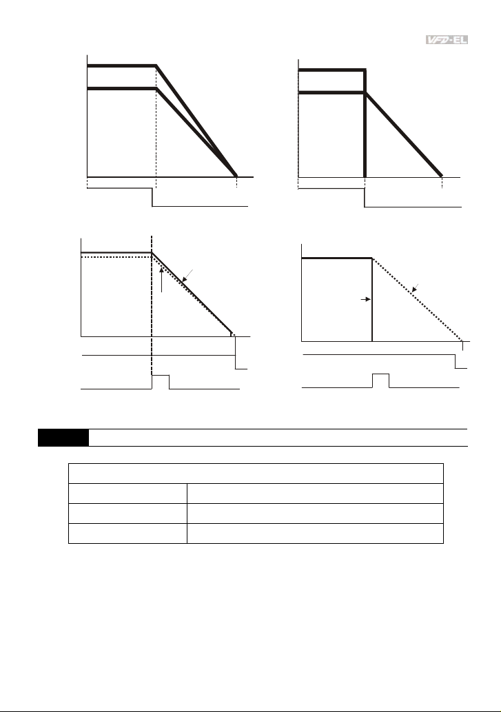
Chapter 4 Parameters|
Frequency
output
frequency
motor
speed
Freque ncy
output
frequency
motor
speed
Time
operation
command
ra mp to sto p an d fre e ru n to st op
operation
command
Frequency
EF
RUN
frequency
output
When Pr.02.02 is set to 0 or 1
free run to stop
operation
command
Frequency
operation
command
EF
stops according to
RUN
When Pr.02.02 is set to 2 or 3
decel eration time
STOP
frequency output
motor
speed
stops according to
decel eration time
02.03
This parameter determines the PWM carrier frequency of the AC motor drive.
PWM Carrier Frequency Selections
115V/230V/460V Series
Power 0.25 to 5hp (0.2kW to 3.7kW)
Setting Range 2 to 12 kHz
Factory Setting 8 kHz
STOP
motor
speed
free run to stop
Unit: 1
Time
Revision August 2008, 2ELE, V1.02 4-39
Page 83
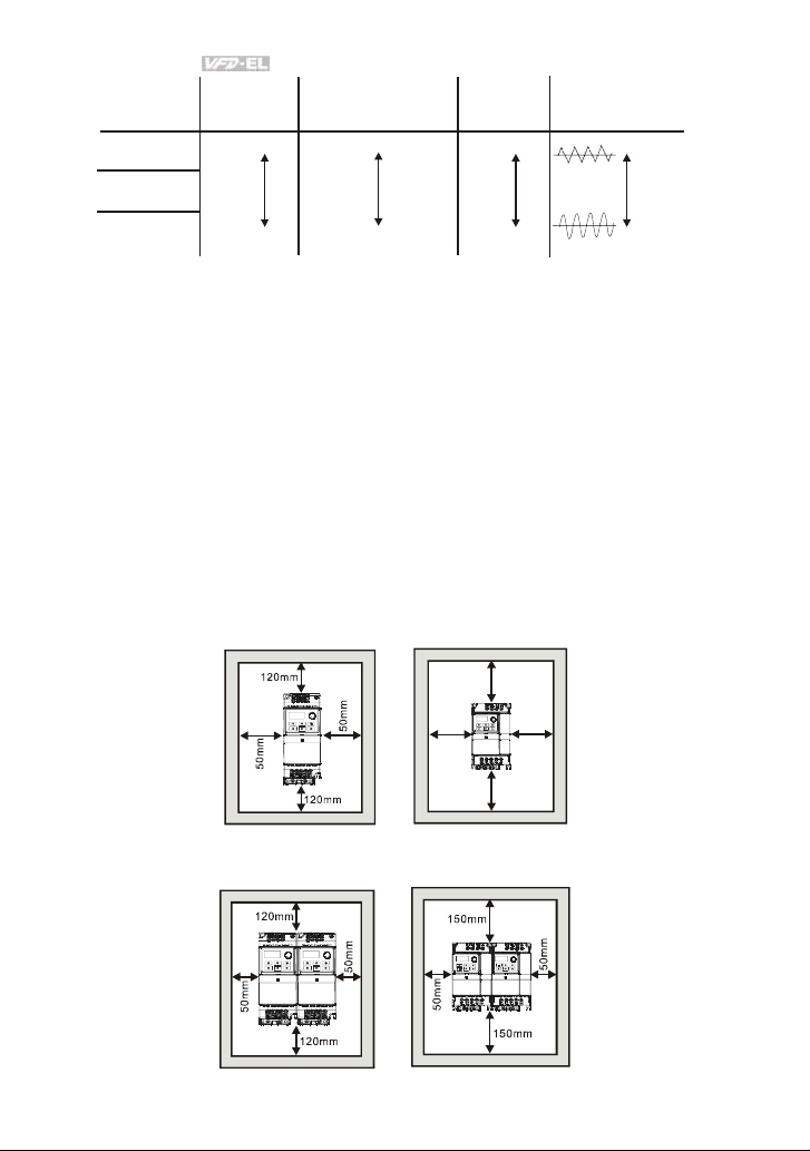
Chapter 4 Parameters|
Carrier
Frequency
2kHz
8kHz
Acoustic
Noise
Significant
Electromagnetic
Noise or leakage
c ur re nt
Minimal
Heat
Dissipation
Minimal
Current
Wave
Minimal
12kHz
Minimal
Significant
Significant
Signifi cant
From the table, we see that the PWM carrier frequency has a significant influence on the
electromagnetic noise, AC motor drive heat dissipation, and motor acoustic noise.
The PWM carrier frequency will be decreased automatically by the ambient temperature and
output current of the AC motor drives. It is used to prevent AC motor drive overheat and
extend IGBT’s life. Therefore, it is necessary to have this kind of protection method. Take an
example of 460V models, assume that the carrier frequency is 12kHz, ambient temperature is
50 degrees C with single AC motor drive. If the output current exceeds 80% * rated current,
the AC motor drive will decrease the carrier frequency automatically by the following chart. If
output current is around 100% * rated current, the carrier frequency will decrease from 12k Hz
to 8k Hz.
Mounting method
Method A
Frame A
Frame B
150mm
m
m
0
5
150mm
m
m
0
5
Method B
Frame A
Frame B
4-40 Revision August 2008, 2ELE, V1.02
Page 84
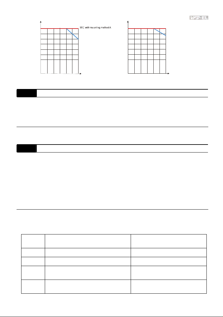
Chapter 4 Parameters|
y
g
y
35 wit h mounting method A
100%
90%
)
%
(
t
80%
n
e
r
r
u
70%
C
d
60%
e
t
a
R
50%
40%
25 with mounting meth od B
℃
meth od A
℃
50 with mountin
40 wit h mounting method B
℃
100%
90%
)
%
(
t
80%
n
e
r
r
70%
u
C
d
60%
e
t
a
R
50%
40%
℃
25 wit h mounting method B
℃
50 with mounting method A
℃
40 with mounting method B
℃
2kHz
4kHz 8kHz
10kHz
6kHz
For 460V Series
12kHz
Carrier
Frequenc
2kHz
4kHz 8kHz
For 115V/230V Se ries
6kHz
10kHz
12kHz
Carrier
Frequenc
02.04 Motor Direction Control
Factory Setting: 0
Settings 0 Forward/Reverse operation enabled
1 Reverse operation disabled
2 Forward operation disabled
This parameter is used to disable one direction of rotation of the AC motor drive direction of
rotation.
02.05 Line Start Lockout
Factory Setting: 1
Settings 0 Disable. Operation status is not changed even if operation
command source Pr.02.01 is changed.
1 Enable. Operation status is not changed even if operation command
source Pr.02.01 is changed.
2 Disable. Operation status will change if operation command source
Pr.02.01 is changed.
3 Enable. Operation status will change if operation command source
Pr.02.01 is changed.
This parameter determines the response of the drive upon power on and operation command
source is changed.
Pr.02.05 Start lockout (Run when power is ON)
Operation status when operation
command source is changed
0 Disable (AC motor drive will run) Keep previous status
1 Enable (AC motor drive doesn’t run) Keep previous status
2 Disable (AC motor drive will run)
3 Enable (AC motor drive doesn’t run)
Change according to the new
operation command source
Change according to the new
operation command source
Revision August 2008, 2ELE, V1.02 4-41
Page 85
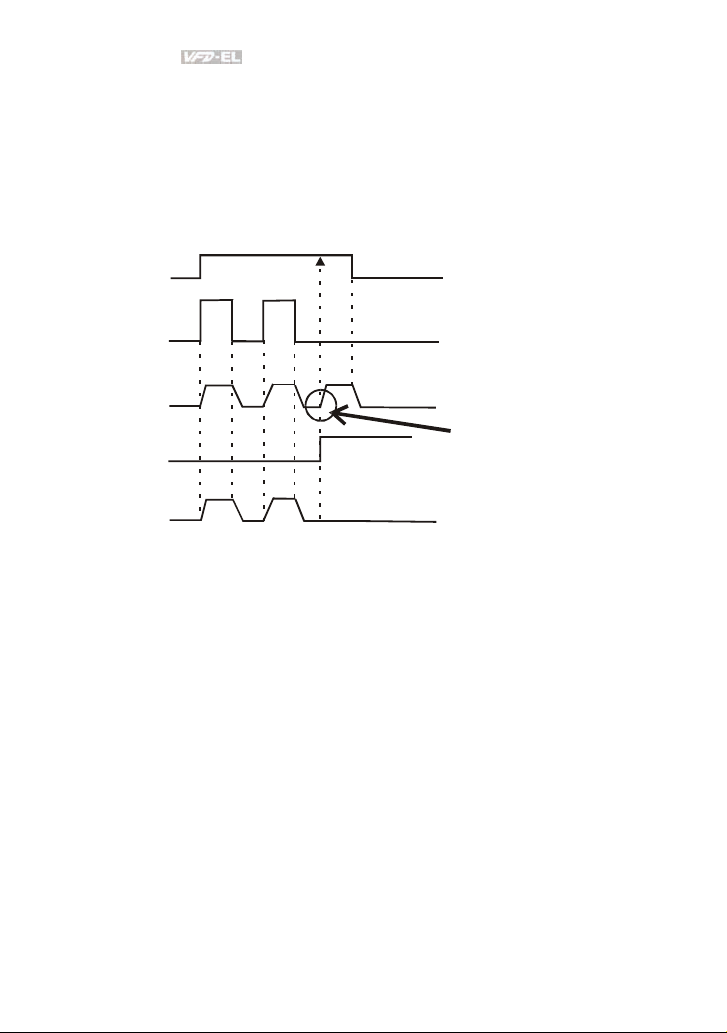
Chapter 4 Parameters|
When the operation command source is from external terminal and operation command is ON
(MI1/MI2-DCM=closed), the AC motor drive will operate according to Pr.02.05 after power is
applied. <For terminals MI1 and MI2 only>
1. When Pr.02.05 is set to 0 or 2, AC motor drive will run immediately.
2. When Pr.02.05 is set to 1 or 3, AC motor drive will remain stopped until operation
command is received after previous operation command is cancelled.
MI1-DCM (clo se)
ON
OFF
Pr.02.01=0
output frequency
Pr.02.05=0 or 2
Change operation
command source
output frequency
Pr.02.05=1 or 3
RUN
STOP
RUN
STOP
Pr.02.01=1 or 2
This action will follow MI1/DCM
or MI2/DCM status
(ON is close/OFF is open)
When the operation command source isn’t from the external terminals, independently from
whether the AC motor drive runs or stops, the AC motor drive will operate according to
Pr.02.05 if the two conditions below are both met.
1. When operation command source is changed to external terminal (Pr.02.01=1 or 2)
2. The status of terminal and AC motor drive is different.
And the operation of the AC motor drive will be:
1. When setting 0 or 1, the status of AC motor drive is not changed by the terminal status.
2. When setting 2 or 3, the status of AC motor drive is changed by the terminal status.
4-42 Revision August 2008, 2ELE, V1.02
Page 86
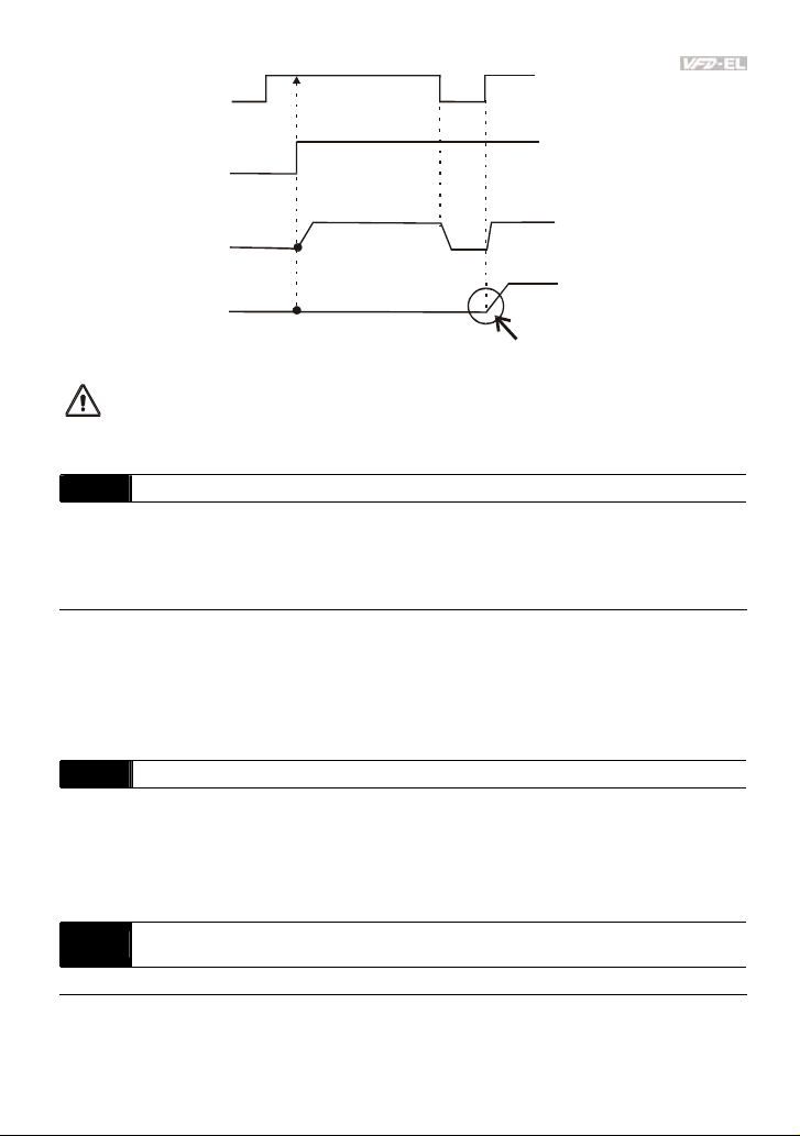
Chapter 4 Parameters|
MI1-DCM (close)
ON
OFF
ON
power is applied
OFF
ON
output frequency
Pr.02.05=0 or 1
it will run
output frequency
Pr.02.05=2 or 3
The Line Start Lockout feature does not guarantee that the motor will never start under this
condition. It is possible the motor may be set in motion by a malfunctioning switch.
02.06 Loss of ACI Signal (4-20mA)
Factory Setting: 0
Settings 0 Decelerate to 0Hz
1 Coast to stop and display “AErr”
2 Continue operation by the last frequency command
This parameter determines the behavior when ACI is lost.
When set to 1, it will display warning message “AErr” on the keypad in case of loss of ACI
signal and execute the setting. When ACI signal is recovered, the warning message will stop
blinking. Please press “RESET” key to clear it.
02.07 Up/Down Mode
Factory Setting: 0
Settings 0 By digital keypad up/down keys mode
1 Based on Accel/Decel Time acc. to Pr.01.09 to 01.12
2 Constant speed (acc. to Pr. 02.08)
3 Pulse input unit (acc. to Pr. 02.08)
Accel/Decel Rate of Change of UP/DOWN Operation with
02.08
Constant Speed
Settings 0.01~10.00 Hz/2ms Factory Setting: 0.01
it won't ru n
when power is applied
It needs to received a run command
after previous command is cancelled
Unit: 0.01
Revision August 2008, 2ELE, V1.02 4-43
Page 87

Chapter 4 Parameters|
These parameters determine the increase/decrease of the master frequency when operated
via the Multi-function Inputs when Pr.04.05~Pr.04.08 are set to 10 (Up command) or 11 (Down
command).
When Pr.02.07 is set to 0: increase/decrease the frequency by using UP/DOWN key. It is valid
only when the AC motor drive is running.
When Pr.02.07 is set to 1: increase/decrease the frequency by acceleration/deceleration
settings. It is valid only when the AC motor drive is running.
When Pr.02.07 is set to 2: increase/decrease the frequency by Pr.02.08.
When Pr.02.07 is set to 3: increase/decrease the frequency by Pr.02.08 (unit: pulse input).
02.11 Keypad Frequency Command Unit: 0.01
Settings 0.00 to 600.0Hz Factory Setting: 60.00
This parameter can be used to set frequency command or read keypad frequency command.
02.12 Communication Frequency Command Unit: 0.01
Settings 0.00 to 600.0Hz Factory Setting: 60.00
This parameter can be used to set frequency command or read communication frequency
command.
The Selections for Saving Keypad or Communication Frequency
02.13
Command
Factory Setting: 0
Settings 0 Save Keypad & Communication Frequency
1 Save Keypad Frequency only
2 Save Communication Frequency only
This parameter is used to save keypad or RS-485 frequency command.
02.14 Initial Frequency Selection (for keypad & RS485)
Factory Setting: 0
Settings 0 By Current Freq Command
1 By Zero Freq Command
2 By Frequency Display at Stop
02.15 Initial Frequency Setpoint (for keypad & RS485) Unit: 0.01
Settings 0.00 ~ 600.0Hz Factory Setting: 60.00
4-44 Revision August 2008, 2ELE, V1.02
Page 88

Chapter 4 Parameters|
These parameters are used to determinate the frequency at stop:
When setting Pr.02.14 to 0: the initial frequency will be current frequency.
When setting Pr.02.14 to 1: the initial frequency will be 0.
When setting Pr.02.14 to 2: the initial frequency will be Pr.02.15.
02.16 Display the Master Freq Command Source
Settings Read Only Factory setting: ##
You can read the master frequency command source by this parameter.
Display Value Bit Function
1 Bit0=1 Master Freq Command Source by First Freq Source (Pr.02.00).
2 Bit1=1 Master Freq Command Source by Second Freq Source (Pr.02.09).
4 Bit2=1 Master Freq Command Source by Multi-input function
02.17 Display the Operation Command Source
Settings Read Only Factory setting: ##
You can read the operation source by this parameter.
Display Value Bit Function
1 Bit0=1 Operation Command Source by Digital Keypad
2 Bit1=1 Operation Command Source by RS485 communication
4 Bit2=1 Operation Command Source by External Terminal
8 Bit3=1 Operation Command Source by Multi-input function
02.18 User-defined Value 2 Setting Unit: 1
Settings 0 to Pr.00.13 Factory Setting: 0
Revision August 2008, 2ELE, V1.02 4-45
Page 89

Chapter 4 Parameters|
Use this parameter to change frequency when (1) Pr.00.13 is not set to 0 and frequency
source is from communication or (2) Pr.02.10 is not set to 0.
02.19 User-defined Value 2 Unit: 1
Settings Read-only Factory Setting: 0
For example: suppose that the frequency source is the first master frequency + second master
frequency command (first master frequency is from keypad and second master frequency is
from AVI), user-defined value 1 is set to 180.0(Pr.00.13 is set to 1800, Pr.00.14 is set to 1).
AVI=2V=180.0/(2V/10V)=36.0, frequency is 36.0/(180.0/60.0)=12.0Hz
Pr.02.18=30.0, frequency is 30.0/(60.0/180.0)=10.0Hz
At this moment, the keypad will display 66.0(36.0+30.0) and the output frequency is
22.0Hz(12.0+10.0). When reading the value from communication address, the value will be
shown as follows: 2102H and 2103H are 22.0Hz, 0212H(Pr.02.18) is 30.0, 0213H(Pr.02.19) is
66.0.
4-46 Revision August 2008, 2ELE, V1.02
Page 90

Chapter 4 Parameters|
Group 3: Output Function Parameters
03.00 Multi-function Output Relay (RA1, RB1, RC1)
Factory Setting: 8
Settings Function Description
No Function
0
1 AC Drive Operational
Master Frequency
2
Attained
3 Zero Speed
4 Over-Torque Detection
Baseblock (B.B.)
5
Indication
6 Low-Voltage Indication
Operation Mode
7
Indication
8 Fault Indication
Desired Frequency
9
Attained
Terminal Count Value
10
Attained
Preliminary Count Value
11
Attained
Over Voltage Stall
12
supervision
Over Current Stall
13
supervision
Active when the drive is ready or RUN command is “ON”.
Active when the AC motor drive reaches the output
frequency setting.
Active when Command Frequency is lower than the
Minimum Output Frequency.
Active as long as over-torque is detected. (Refer to Pr.06.03
~ Pr.06.05)
Active when the output of the AC motor drive is shut off
during baseblock. Base block can be forced by Multi-function
input (setting 09).
Active when low voltage(Lv) is detected.
Active when operation command is controlled by external
terminal.
Active when a fault occurs (oc, ov, oH1, oL, oL1, EF, cF3,
HPF, ocA, ocd, ocn, GFF).
Active when the desired frequency (Pr.03.02) is attained.
Active when the counter reaches Terminal Count Value.
Active when the counter reaches Preliminary Count Value.
Active when the Over Voltage Stall function operating
Active when the Over Current Stall function operating
Revision August 2008, 2ELE, V1.02 4-47
Page 91

Chapter 4 Parameters|
Settings Function Description
Heat Sink Overheat
14
Warning
15 Over Voltage supervision
16 PID supervision
17 Forward command
18 Reverse command
Zero Speed Output
19
Signal
When heatsink overheats, it will signal to prevent OH turn off
the drive. When it is higher than 85
o
C (185oF), it will be ON.
Active when the DC-BUS voltage exceeds level
Active when the PID feedback signal is abnormal (Refer to
Pr.10.12 and Pr.13.)
Active when the direction command is FWD
Active when the direction command is REV
Active when the drive is standby or stop
Communication Warning
20
(FbE,Cexx, AoL2, AUE,
Active when there is a Communication Warning
SAvE)
Brake Control (Desired
21
Frequency Attained)
22 AC Motor Drive Ready
Active when output frequency ≥Pr.03.11. Deactivated when
output frequency ≤Pr.03.12 after STOP command.
Active when AC motor drive is ready.
03.01
Reserved
03.02 Desired Frequency Attained Unit: 0.01
Settings 0.00 to 600.0 Hz Factory Setting: 0.00
If a multi-function output terminal is set to function as Desired Frequency Attained (Pr.03.00
=09), then the output will be activated when the programmed frequency is attained.
4-48 Revision August 2008, 2ELE, V1.02
Page 92

Chapter 4 Parameters|
master freq. attained
(output signal)
desired freq. attained
setting 03 zero speed indication
setting 19 zero speed indication
outpu t timing cha rt of mul tipl e func tion t ermi nals
when setting to frequency attained or zero speed indication
master
frequency
desired
frequency
03.02
run/stop
Frequency
detection range
waiting time
for
frequency
OFF
ON
ON
2Hz
OFF
ON
ON
OFF
OFF
ON
detection
4Hz
range
detection
-2Hz
range
DC braking time
during stop
Time
OFF
OFF
OFF
ON
ON
03.03
Analog Output Signal (AFM)
Factory Setting: 0
Settings 0 Analog Frequency Meter (0 to Maximum Output Frequency)
1 Analog Current Meter (0 to 250% of rated AC motor drive current)
This parameter sets the function of the AFM output 0~+10VDC (ACM is common).
03.04 Analog Output Gain Unit: 1
Settings 1 to 200% Factory Setting: 100
This parameter sets the voltage range of the analog output signal AFM.
When Pr.03.03 is set to 0, the analog output voltage is directly proportional to the output
frequency of the AC motor drive. With Pr.03.04 set to 100%, the Maximum Output Frequency
(Pr.01.00) of the AC motor drive corresponds to +10VDC on the AFM output.
Similarly, if Pr.03.03 is set to 1, the analog output voltage is directly proportional to the output
current of the AC drive. With Pr.03.04 set to 100%, then 2.5 times the rated current
corresponds to +10VDC on the AFM output.
NOTE
Any type of voltmeter can be used. If the meter reads full scale at a voltage less than 10V, Pr.
03.04 should be set using the following formula:
Pr. 03.04 = ((meter full scale voltage)/10) x 100%
Revision August 2008, 2ELE, V1.02 4-49
Page 93

Chapter 4 Parameters|
For Example: When using the meter with full scale of 5 volts, adjust Pr.03.04 to 50%. If
Pr.03.03 is set to 0, then 5VDC will correspond to Maximum Output Frequency.
03.05 Terminal Count Value Unit: 1
Settings 0 to 9999 Factory Setting: 0
This parameter sets the count value of the internal counter. To increase the internal counter,
one of Pr.04.05 to 04.08 should be set to 12. Upon completion of counting, the specified output
terminal will be activated. (Pr.03.00 set to 10).
When the display shows c555, the drive has counted 555 times. If display shows c555•, it
means that real counter value is between 5,550 and 5,559.
03.06 Preliminary Count Value Unit: 1
Settings 0 to 9999 Factory Setting: 0
When the counter value reaches this value, the corresponding multi-function output terminal
will be activated, provided one of Pr.03.00set to 11 (Preliminary Count Value Setting). This
multi-function output terminal will be deactivated upon completion of Terminal Count Value
Attained.
The timing diagram:
Display
(Pr.00.04=1)
Counter Trigger
Preliminary Count Value
(Pr. 03.00=11)
Te rm in al Co unt Val ue
(Pr. 03.00=10)
TRG
Ex:03.05=5,0 3.06=3
The width of trigger signal
shou ld not b e less tha n
2ms(<250 Hz)
2msec
2msec
03.07 EF Active when Terminal Count Value Attained
Factory Setting: 0
Settings 0 Terminal count value attained, no EF display
1 Terminal count value attained, EF active
If this parameter is set to 1 and the desired value of counter is attained, the AC drive will treat
it as a fault. The drive will stop and show the “EF” message on the display.
4-50 Revision August 2008, 2ELE, V1.02
Page 94

Chapter 4 Parameters|
1
03.08 Fan Control
Factory Setting: 0
Settings 0 Fan always ON
1 1 minute after AC motor drive stops, fan will be OFF
2 Fan ON when AC motor drive runs, fan OFF when AC motor drive
stops
3 Fan ON when preliminary heatsink temperature attained
This parameter determines the operation mode of the cooling fan.
03.09
Reserved
03.10
Reserved
03.11 Brake Release Frequency Unit: 0.01
Settings 0.00 to 600.0Hz Factory Setting: 0.00
03.12 Brake Engage Frequency Unit: 0.01
Settings 0.00 to 600.0Hz Factory Setting: 0.00
These two parameters are used to set control of mechanical brake via the output terminals
(Relay) when Pr.03.00is set to 21. Refer to the following example for details.
Example:
1. Case 1: Pr.03.12 ≥ Pr.03.11
2. Case 2: Pr.03.12 ≤ Pr.03.11
Frequency
Output
Case 1: Pr.03.12
Case 2: Pr.03.12
Case 1: Pr.03.00=21
Case 2: Pr.03.00=2
Pr. 03.11
Time
Run/Stop
Revision August 2008, 2ELE, V1.02 4-51
Page 95

Chapter 4 Parameters|
03.13 Display the Status of Relay
Settings Read Only Factory setting: ##
For standard AC motor drive, the multi-function output terminals are falling-edge triggered.
0: Relay is ON; 1: Relay is OFF.
4-52 Revision August 2008, 2ELE, V1.02
Page 96

Chapter 4 Parameters|
Group 4: Input Function Parameters
04.00 Keypad Potentiometer Bias Unit: 0. 1
Settings 0.0 to 100.0% Factory Setting: 0.0
04.01 Keypad Potentiometer Bias Polarity
Factory Setting: 0
Settings 0 Positive Bias
1 Negative Bias
04.02 Keypad Potentiometer Gain Unit: 0.1
Settings 0.1 to 200.0% Factory Setting: 100.0
Keypad Potentiometer Negative Bias, Reverse Motion
04.03
Enable/Disable
Factory Setting: 0
Settings 0 No Negative Bias Command
1 Negative Bias: REV Motion Enabled
Example 1: Standard application
This is the most used setting. The user only needs to set Pr.02.00 to 04. The frequency command
comes from keypad potentiometer.
60Hz
30Hz
0Hz
0V
5V
Pr.01.00=60Hz--Max. output Freq.
Potentiometer
Pr.04.00 =0%--Bias adjustment
Pr.04.01 =0--Positive bias
Pr.04.02 =100%--Input gain
Pr.04.03 =0--No negative bias command
10V
Example 2: Use of bias
This example shows the influence of changing the bias. When the input is 0V the output frequency is
10 Hz. At mid-point a potentiometer will give 40 Hz. Once the Maximum Output Frequency is reached,
any further increase of the potentiometer or signal will not increase the output frequency. (To use the
full potentiometer range, please refer to Example 3.) The value of external input voltage/current 0-
8.33V corresponds to the setting frequency 10-60Hz.
Revision August 2008, 2ELE, V1.02 4-53
Page 97
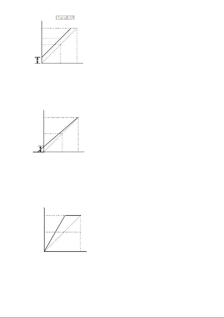
Chapter 4 Parameters|
60Hz
40Hz
10Hz
Bias
Adjustment
Example 3: Use of bias and gain for use of full range
This example also shows a popular method. The whole scale of the potentiometer can be used as
desired. In addition to signals of 0 to 10V, the popular voltage signals also include signals of 0 to 5V,
or any value under 10V. Regarding the setting, please refer to the following examples.
Bias
Adjustment
0Hz
60Hz
10Hz
-2V
XV
0Hz
0V
0V
5V
5V
Pr.01.00=60Hz--Max. output Freq.
Potentiometer
Pr.04.00 =16.7%--Bias adjustment
Pr.04.01 =0--Positive bias
Pr.04.02 =100%--Input gain
Pr.04.03 = 0--No negative bias command
Gain:100%
10V
Bias adjustment:((10Hz/60Hz)/(Gain/100%))*100%=16.7%
Pr.01.00=60Hz--Max. output Freq.
Potentiometer
Pr.04.00 =20.0%--Bias adjustment
Pr.04.01 =0--Positive bias
Pr.04 .02 =83.3%- -In put ga in
Pr.04.03 =0--No negative bias command
Gain:(10V/(10V+2V))*100%=83.3%
10V
Bias adjustment:((10Hz/60Hz)/(Gai n/100%))*100%=20.0%
Example 4: Use of 0-5V potentiometer range via gain adjustment
This example shows a potentiometer range of 0 to 5 Volts. Instead of adjusting gain as example
below, you can set Pr. 01.00 to 120Hz to achieve the same results.
Gain
60Hz
adjustment
30Hz
10V
0Hz 0V
5V
Pr.01.00=60H z--Max. output Freq.
Potentiometer
Pr.04.00 =0.0%--Bias adjustment
Pr.04.01 =0--Positive bias
Pr.04.02 =200%--Input gain
Pr.04.03 =0--No negative bias command
Gain:(10V/5V)*100%=200%
4-54 Revision August 2008, 2ELE, V1.02
Page 98
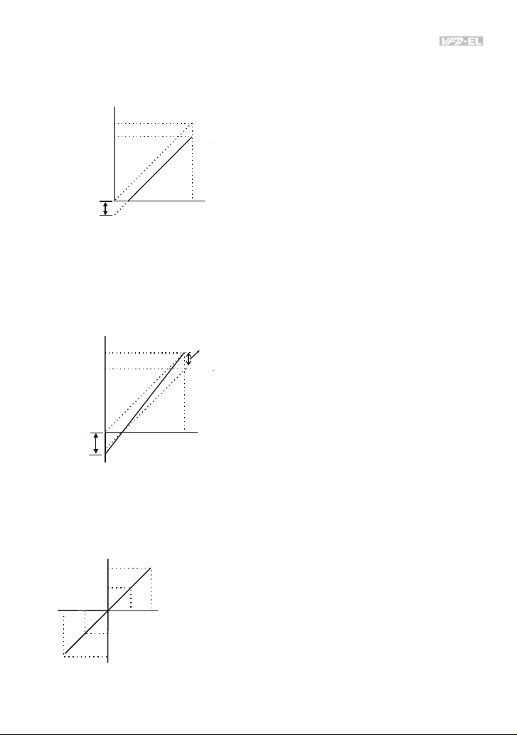
Chapter 4 Parameters|
Example 5: Use of negative bias in noisy environment
In this example, a 1V negative bias is used. In noisy environments it is advantageous to use negative
bias to provide a noise margin (1V in this example).
Pr.01.00=60Hz--Max. output Freq.
Potentiometer
Pr.04.00 =10.0%--Bias adjustment
Pr.04.01 =1--Negative bias
Pr.04.02 =100%--Input gain
Pr.04.03 =0--No negative bias command
Gain:100%
10V
Bias adjustment:((6Hz/60Hz)/(Gain/100%))*100%=10.0%
Negative
bias 6Hz
60Hz
54Hz
0Hz
0V
1V
Example 6: Use of negative bias in noisy environment and gain adjustment to use full
potentiometer range
In this example, a negative bias is used to provide a noise margin. Also a potentiometer frequency
gain is used to allow the Maximum Output Frequency to be reached.
Bias
Negative
bias 6.6Hz
60Hz
0Hz
0V
adjustment
1V
Pr.01.00=6 0Hz--Max. output Freq.
Potentiometer
Pr.04.00 =10 .0%--Bias adjustment
Pr.04.01 =1--Negative bias
Pr.04.02 =111%--Input gain
Pr.04.03 =0--No negative bias command
Gain:(10V/9V)*100%=111%
Bias adjustment:((6.6Hz/60Hz)/(Gain/100%))*100%=10.0%
10V
Example 7: Use of 0-10V potentiometer signal to run motor in FWD and REV direction
In this example, the input is programmed to run a motor in both forward and reverse direction. The
motor will be idle when the potentiometer position is at mid-point of its scale. Using the settings in this
example disables the external FWD and REV controls.
Pr.01.00=60Hz--Max. output Freq.
Potentiometer
Pr.04.00 =50.0%--Bias adjustment
Pr.04.01 =1--Negative bias
Pr.04.02 =200%--Input gain
10V
Pr.04.03 =1--Negative bias: REV motion enabled
Gain:(10V/5V)*100%=200%
Bias adjustment:((60Hz/60Hz)/(Gain/100%))*100%=200%
0V
60Hz
30Hz
0Hz
REV
FWD
5V
30Hz
60Hz
Revision August 2008, 2ELE, V1.02 4-55
Page 99

Chapter 4 Parameters|
Example 8: Use negative slope
In this example, the use of negative slope is shown. Negative slopes are used in applications for
control of pressure, temperature or flow. The sensor that is connected to the input generates a large
signal (10V) at high pressure or flow. With negative slope settings, the AC motor drive will slow stop
the motor. With these settings the AC motor drive will always run in only one direction (reverse). This
can only be changed by exchanging 2 wires to the motor.
60Hz
negative slope
Pr.01.00=60Hz--Max. output Freq.
Potentiometer
Pr.04.00 =100%--Bias adjustment
Pr.04.01 =0--Positive bias
Pr.04.02 =100%--Input gain
Pr.04.03 =1--Negative bias: REV motion enabled
0Hz
0V
04.11 Minimum AVI Voltage Unit: 0.1
Settings 0.0 to 10.0V Factory Setting: 0.0
04.12 Minimum AVI Frequency (percentage of Pr.01.00) Unit: 0.1
Settings 0.0 to 100.0% Factory Setting: 0.0
04.13 Maximum AVI Voltage Unit: 0.1
Settings 0.0 to 10.0V Factory Setting: 10.0
04.14 Maximum AVI Frequency (percentage of Pr. 01.00) Unit: 0.1
Settings 0.0 to 100.0% Factory Setting: 100.0
04.15 Minimum ACI Current Unit: 0.1
Settings 0.0 to 20.0mA Factory Setting: 4.0
04.16 Minimum ACI Frequency (percentage of Pr. 01.00) Unit: 0.1
Settings 0.0 to 100.0% Factory Setting: 0.0
04.17 Maximum ACI Current Unit: 0.1
Settings 0.0 to 20.0mA Factory Setting: 20.0
04.18 Maximum ACI Frequency (percentage of Pr. 01.00) Unit: 0.1
Settings 0.0 to 100.0% Factory Setting: 100.0
The above parameters are used to set the analog input reference values. The min and max
frequencies are based on Pr.01.00 (during open-loop control) as shown in the following.
Gain:(10V/10V)*100%=100%
10V
Bias adjustment:((60Hz/60Hz)/(Gain/100%))*100%=100%
4-56 Revision August 2008, 2ELE, V1.02
Page 100
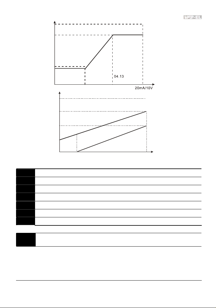
Chapter 4 Parameters|
04.14
04.18
04.12
04.16
04.14=70
04.18=50
01.00
01.00=60 .00 Hz
04.11
04.15
AVI
04.17
analog input
04.12=30
04.16=0
04.11=0V
04.15=4mA
ACI
04.13=10 V
04.17=20 mA
analog input
04.19
Reserved
04.20
Reserved
04.21
Reserved
04.22
Reserved
04.23
Reserved
04.24
Reserved
04.25
Reserved
Multi-function Input Terminal (MI1, MI2) 2-wire/ 3-wire Operation
04.04
Control Modes
Factory Setting: 0
Settings 0 2-wire: FWD/STOP, REV/STOP
1 2-wire: FWD/REV, RUN/STOP
2 3-wire Operation
Revision August 2008, 2ELE, V1.02 4-57
 Loading...