

Delta Electronics UPS102N2002N0B0, UPS302N2002N0B0, UPS102N2000N0B0, UPS202N2000N0B0, UPS302N2000N0B0 User Manual
...
The power behind competitiveness
Delta UPS - Amplon Family
N Series, Single Phase
1/ 2/ 3 kVA
User Manual
www.deltapowersolutions.com

Save This Manual
This manual contains important instructions and warnings that you should
follow during the installation, operation, storage and maintenance of this
product. Failure to heed these instructions and warnings will void the warranty.
Copyright © 2015 by Delta Electronics Inc. All Rights Reserved. All rights of this
User Manual (“Manual”), including but not limited to the contents, information,
and figures are solely owned and reserved by Delta Electronics Inc. (“Delta”).
The Manual can only be applied to the operation or the use of this product. Any
disposition, duplication, dissemination, reproduction, modification, translation,
extraction, or usage of this Manual in whole or in part is prohibited without the prior
written permission of Delta. Given that Delta will continuously improve and develop
the product, changes may be made to the information in this Manual at any time
without obligation to notify any person of such revision or changes. Delta will make
all possible efforts to secure the accuracy and the integrity of this Manual. Delta
disclaims any kinds or forms of warranty, guarantee, or undertaking, either expressly
or implicitly, including but not limited to the completeness, faultlessness, accuracy,
non-infringement, merchantability or tness for a particular purpose of the Manual.
Amplon N Series
II

Table of Contents
Table of Contents
Chapter 1 : Important Safety Instructions --------------------------- 1
1.1 Safety Instructions ---------------------------------------------- 1
1.2 Storage ------------------------------------------------------------- 4
Chapter 2 : Introduction --------------------------------------------------- 5
2.1 General Overview ----------------------------------------------- 5
2.2 Exterior & Dimensions ----------------------------------------- 5
2.3 Package List ------------------------------------------------------ 6
Chapter 3 : Operation Panel ---------------------------------------------- 8
3.1 LED Indicators --------------------------------------------------- 8
3.2 Multi-function Buttons ------------------------------------------ 9
3.3 LCD Display -----------------------------------------------------11
3.4 7-Segment Display ---------------------------------------------14
3.5 Flow Chart of the 7-Segment Display ---------------------16
Chapter 4 : Rear Panel ----------------------------------------------------18
Chapter 5 : Operation Modes -------------------------------------------20
5.1 Standby Mode ---------------------------------------------------20
5.2 On-line Mode ---------------------------------------------------20
5.3 Bypass Mode ----------------------------------------------------20
5.4 Battery Mode ----------------------------------------------------20
5.5 Setup Mode -----------------------------------------------------21
Chapter 6 : Turn-on & Turn-off Procedures ------------------------23
6.1 Turn-on Procedures --------------------------------------------23
6.1.1 Normal Start-up --------------------------------------------------------- 23
6.1.2 Cold Start ----------------------------------------------------------------- 23
6.2 Turn-off Procedures --------------------------------------------24
Chapter 7 : Alarm -----------------------------------------------------------25
Chapter 8 : Optional Accessories -------------------------------------26
III

Chapter 9 : Troubleshooting --------------------------------------------27
Chapter 10 : Maintenance ------------------------------------------------30
10.1 UPS ----------------------------------------------------------------30
10.2 Batteries ----------------------------------------------------------30
10.3 Fan -----------------------------------------------------------------31
Appendix 1 : Technical Specications-------------------------------32
Appendix 2 : Warranty ----------------------------------------------------34
Amplon N Series
IV

Chapter 1 Important Safety Instructions
Chapter 1 : Important Safety Instructions
1.1 Safety Instructions
Installation Warnings
z
z
Before installation and usage, please read this User Manual thoroughly. This
helps you to use the product correctly and safely.
z
z
Install the UPS in a well-ventilated area, away from excess moisture, heat, dust,
ammable gas or explosives.
z
z
To avoid re accidents and electric shock, please install the UPS in a temperate and humidity well-controlled indoor area free of conductive contaminants.
For the temperature and humidity specications, please refer to Appendix 1 :
Technical Specications.
z
z
Leave adequate space (at least 15cm) around all sides of the UPS for proper
ventilation.
Connection Warnings
z
z
The UPS must be well grounded due to a possible risk of current leakage.
z
z
The installation of upstream and downstream protective devices is highly recommended when the UPS is connected to the mains and the loads.
z
z
The protective devices connecting to the UPS must be installed near the UPS
and must be easily accessible for operation.
z
z
Do not use extension cords to connect the UPS to an AC outlet.
z
z
Do not plug the UPS’s input power cord (provided) into its own output sockets.
z
z
If you need to move the UPS or perform re-wiring, please turn off the AC input
power and ensure that the UPS has been safely shutdown. Otherwise, the output end might still be energized, which might cause electric shock.
z
z
The UPS output cable should be shorter than 10m.
1

Usage Warnings
z
z
This is a class-A product. In a domestic environment, this product may cause radio interference, in which case, the user is required to take adequate measures.
z
z
The UPS can be used to power computers and associated peripheral devices,
such as monitors, modems, cartridge tape drives, external hard drives, etc.
z
z
It is strictly forbidden to connect the UPS with:
1. any regenerative-type loads.
2. any asymmetrical loads (ex. half-wave rectier).
z
z
To ensure reliable operation of the UPS and to protect the UPS from overheating, the slits and openings in the UPS must not be blocked or covered.
z
z
Before usage, you must allow the UPS to adjust to room temperature for at least
one hour to avoid moisture condensing inside the UPS.
z
z
Do not pour and splash any liquid on the UPS. Do not insert any object into
the UPS’s slits and openings. Do not put beverage containers on or around the
UPS.
z
z
When an emergency occurs, press the OFF button ( ) and release it after
you hear one beep to turn off the UPS. Cut off the input power to completely
shut down the UPS.
z
z
Do not use any cleaning liquid or cleaning spray to clean the UPS. Before cleaning, please make sure that the UPS has been completely shut down, the UPS’s
input power cord has been unplugged, and the built-in batteries have been disconnected.
z
z
All maintenance services must be performed by qualified service personnel.
Forbid opening or removing the cover of the UPS to avoid high voltage electric
shock.
z
z
You must contact qualied service personnel if either of the following events occur:
1. Liquid is poured or splashed on the UPS.
2. The UPS does not run normally after this User Manual is carefully
observed.
NOTE :
If you use the UPS in an area that generates or incurs dust, you should
install a dust lter in the UPS to ensure normal product life and function.
Amplon N Series
2
Battery Warnings
Chapter 1 Important Safety Instructions
Model Device No.
UPS102N2000N0B0 1kVA 24Vdc
Standard
Model
Long
Backup
Model
z
z
Keep the batteries away from heat sources. Do not open or mutilate the batter-
UPS202N2000N0B0 2kVA 48Vdc
UPS302N2000N0B0 3kVA 72Vdc
UPS102N2002N0B0 1kVA 24Vdc
UPS202N2002N0B0 2kVA 48Vdc
UPS302N2002N0B0 3kVA 72Vdc
UPS
Rating
Battery
Voltage
Note
1. There are two sealed lead-acid
built-in batteries.
2. The UPS cannot connect any
external battery pack.
1. There are four sealed lead-acid
built-in batteries.
2. The UPS cannot connect any
external battery pack.
1. There are six sealed lead-acid
built-in batteries.
2. The UPS cannot connect any
external battery pack.
1. There is no built-in battery.
2. The UPS can connect external
battery pack(s).
ies. The released electrolyte is harmful to the skin and eyes and may be toxic.
z
z
A battery can present a risk of electric shock and high short-circuit current.
z
z
Servicing of batteries must be performed or supervised by qualied service personnel knowledgeable in batteries and the required precautions. Keep unauthorized personnel away from batteries.
z
z
The risk of electric shock and short-circuit current is possible when the batteries
are connected to the UPS. Before maintenance, disconnect all batteries to cut
off the battery power.
z
z
For battery replacement, only use the same number and type of batteries.
z
z
Observe the following before replacing the batteries:
1. Remove watches, rings, or other metal objects.
2. Use tools with insulated handles.
3

3. Wear rubber gloves and boots.
4. Do not lay tools or metal parts on the top of batteries.
5. Before battery removal, replacement or installation, disconnect any circuit
connected to the batteries.
z
z
Do not connect the batteries in reverse; otherwise, a risk of electric shock or re
accidents might occur.
WARNING:
The risk of electric shock and short-circuit current is possible when
the batteries are still connected to the UPS even though the UPS is
disconnected from the mains. Do not forget to cut off the battery source
before maintenance.
1.2 Storage
z
z
Prior to installation
If the UPS needs to be stored prior to installation, it should be placed in a
dry area. The allowable storage temperature is between -15°C and +50°C
(5°F~122°F).
z
z
After usage
Press the
the utility power, remove all equipment from the UPS, and store the UPS in a dry
and well-ventilated area at a temperature between -15°C and +50°C (5°F~122°F).
Idle batteries must be recharged fully approximately every three months if the
UPS needs to be stored for an extended period of time. The charging time must
not be less than 24 hours each time.
NOTE :
After storage and before start-up of the UPS, you must allow the UPS to
adjust to room temperature (20°C~25°C or 68°F~77°F) for at least one
hour to avoid moisture condensing inside the UPS.
Amplon N Series
button, make sure the UPS is shutdown, disconnect the UPS from
4
Chapter 2 Introduction
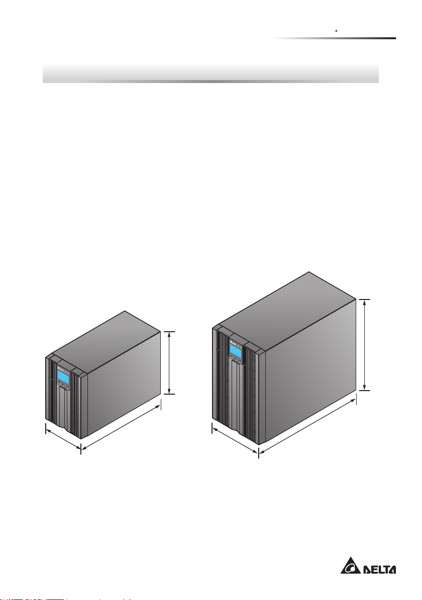
325mm
Chapter 2 : Introduction
2.1 General Overview
The N series UPS is a single-phase on-line UPS providing reliable and consistent
sine-wave quality power to your electronic equipment. It adopts the latest technology and the highest quality components providing output power factor up to 0.9 and
its efciency in on-line mode can reach at maximum 93%. The UPS not only provides safe, reliable and uninterrupted power to your sensitive electronic equipment
at all times, but also produces greater electronic power efciency at less cost. Its
compact design does not occupy much space and is easy to use. There are three
different ratings (1kVA, 2kVA and 3kVA) for your selection.
2.2 Exterior & Dimensions
145mm
(Figure 2-1 : 1 kVA
Exterior & Dimensions)
320mm
225mm
190mm
(Figure 2-2 : 2/3 kVA
Exterior & Dimensions)
5
390mm
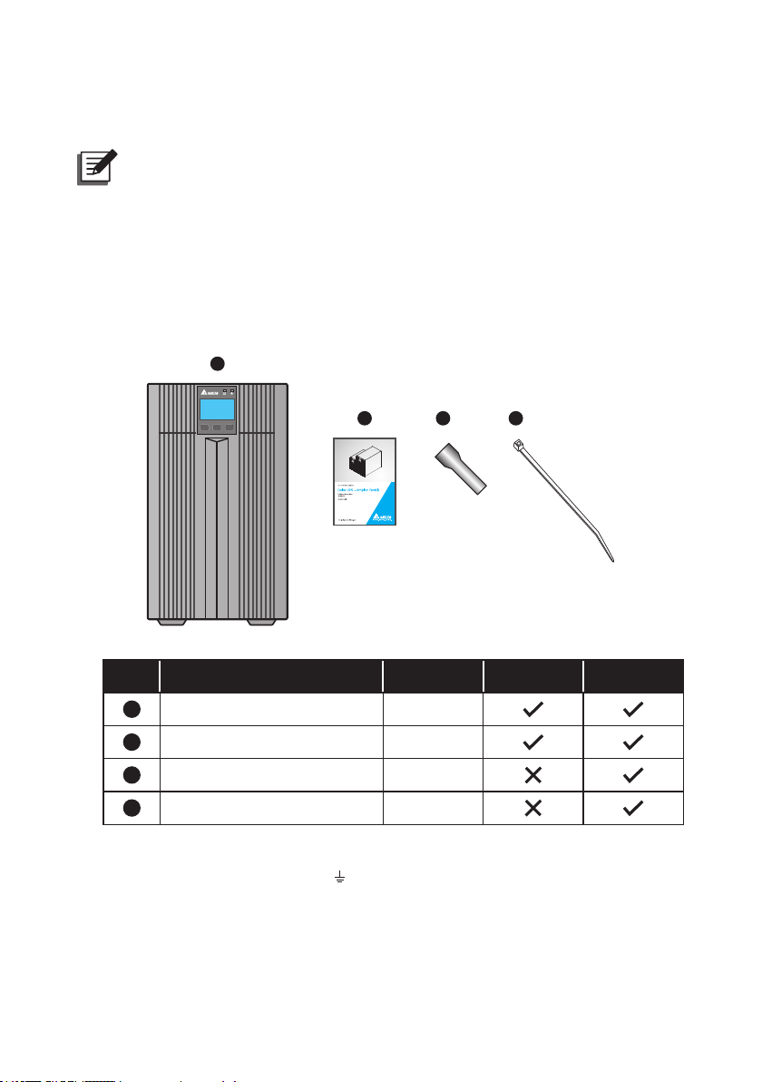
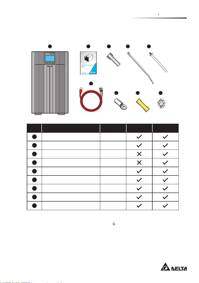
2.3 Package List
NOTE :
1. If there is any damage or anything missing, please immediately contact
the dealer from whom you purchased the unit.
2. If the UPS needs to be returned, carefully repack the UPS and all of the
accessories using the original packing material that came with the unit.
z
z
Standard Model: UPS102N2000N0B0 (1kVA)/ UPS202N2000N0B0 (2kVA)/
UPS302N2000N0B0 (3kVA):
1
ON
SETUP
OFF
2 3
4
No. Item Q’ty 1/ 2kVA 3kVA
1
UPS 1 PC
2
User Manual 1 PC
3
Terminal Copper *
4
Cable Tie *
1
: The terminal copper (3 PCS) and cable tie (1 PC) are used to connect the
*
UPS output terminals ( L, N,
1
3 PCS
1
1 PC
) located at the rear of the 3kVA UPS.
Amplon N Series
6
Chapter 2 Introduction
z
z
Long Backup Model: UPS102N2002N0B0 (1kVA)/ UPS202N2002N0B0
(2kVA) / UPS302N2002N0B0 (3kVA):
1 2 3
ON
SETUP
OFF
6
4
7 8 9
5
No. Item Q’ty 1/ 2kVA 3kVA
1
UPS 1 PC
2
User Manual 1 PC
3
Terminal Copper *1 3 PCS
1
4
Cable Tie (Type A) *
5
Cable Tie (Type B) *
6
Battery Wire 1 PC
7
Ring-type Thimble *
8
9
2
Joint *
Wire Mount *
1
2
2
1 PC
1 PC
2 PCS
2 PCS
2
1 PC
1
: The terminal copper (3 PCS) and cable tie (Type A: 1 PC) are used to
*
connect the UPS output terminals ( L, N,
) located at the rear of the 3kVA
UPS.
2
: If the provided battery wire (1 PC) is not long enough and you want to use
*
a longer battery wire (not provided), please use the provided joint (2 PCS),
ring-type thimble (2 PCS), cable tie (Type B: 1 PC) and wire mount (1 PC) to
join them together.
7
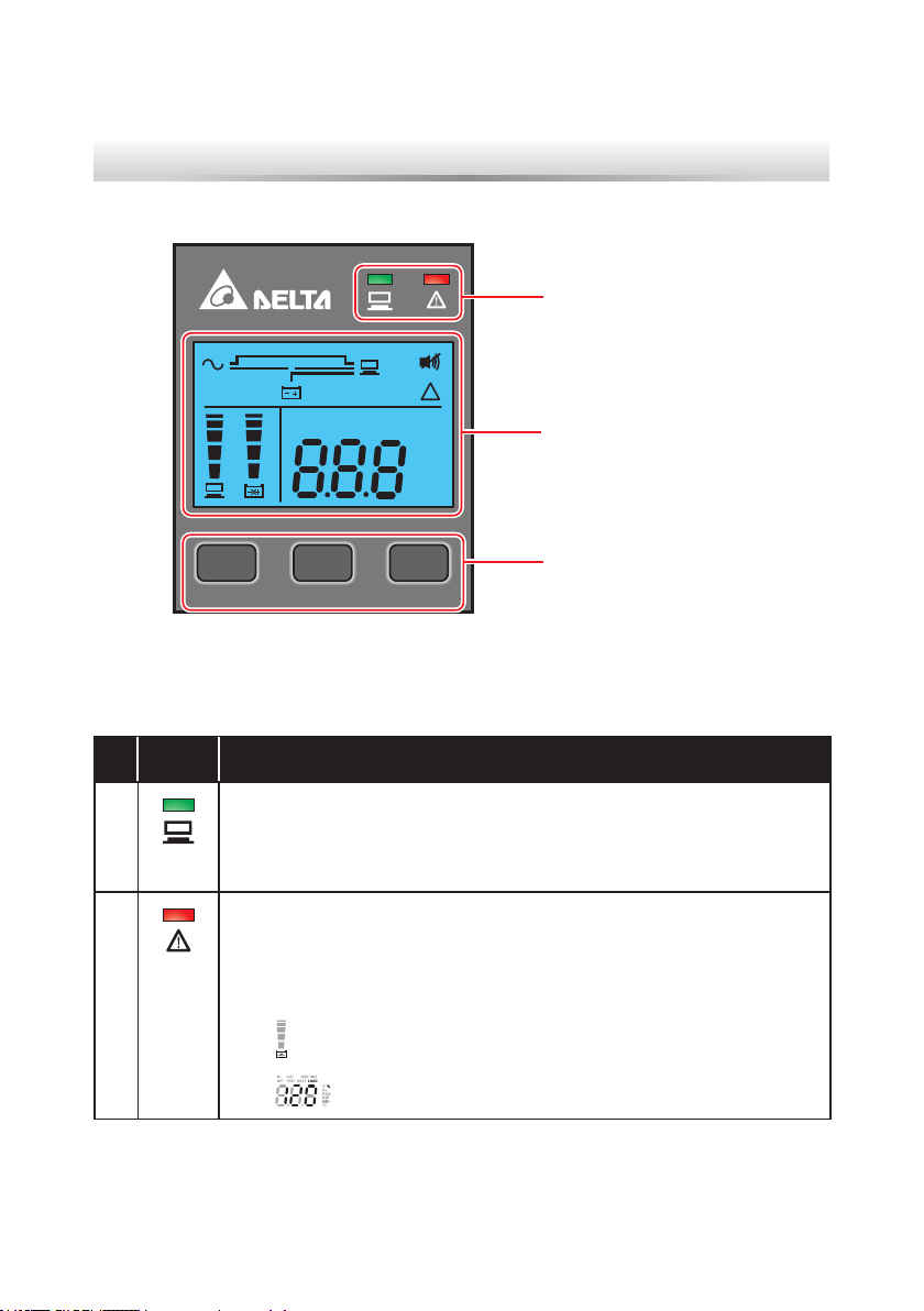
Chapter 3 : Operation Panel
3.1 LED Indicators
!
IN OUT
RUN TIME
SETUP
SET TEST BATT LOAD
ON
V
Hz
KVA
KW
MIN
°C
OFF
%
3.1 LED Indicators
No. LED Description
3.3 LCD Display (inclduing
3.4 7-Segment Display)
3.2 Multi-function Buttons
1
2
Amplon N Series
Indicates the output status.
1. ON (green): There is output
2. OFF: There is no output
1. ON (red): The UPS detects an internal fault or an environmental
fault. You could refer to 3.3 LCD Display - No. 9 for more information.
2. Flashing (red): The UPS has the following warning message(s).
a.
:There is no battery or battery replacement is needed.
b.
:The UPS is overloaded.
8
 Loading...