

Page 1

Broadband Wireless Access (BWA) System
IP-based
EasyWiFi
WiFi Extension
Module for the EasyST Unit
Hardware Installation Guide
The Innovation Behind Broadband Wireless
Connecting the World
Page 2

Page 3

Revision Record: EasyWiFi
Pub. No. Date Update Description
01 Dec-05 First edition. Author: MD
02 03-06 Additional Input: Author: MF
Publication No. : 18120511-01
© Copyright by Airspan Networks Inc., 2005. All rights reserved worldwide.
The information contained in this document is proprietary and is subject to all relevant copyright, patent and other
laws protecting intellectual property, as well as any specific agreement protecting Airspan Networks Inc. rights in
the aforesaid information. Neither this document nor the information contained herein may be published,
reproduced or disclosed to third parties, in whole or in part, without the express, prior, written permission of
Airspan Networks Inc. In addition, any use of this document or the information contained herein for any purposes
other than those for which it was disclosed is strictly forbidden.
Airspan Networks Inc. reserves the right, without prior notice or liability, to make changes in equipment design or
specifications.
Information supplied by Airspan Networks Inc. is believed to be accurate and reliable. However, no responsibility
is assumed by Airspan Networks Inc. for the use thereof nor for the rights of third parties which may be effected in
any way by the use thereof.
Any representation(s) in this document concerning performance of Airspan Networks Inc. product(s) are for
informational purposes only and are not warranties of future performance, either express or implied. Airspan
Networks Inc. standard limited warranty, stated in its sales contract or order confirmation form, is the only warranty
offered by Airspan Networks Inc. in relation thereto.
This document may contain flaws, omissions or typesetting errors; no warranty is granted nor liability assumed in
relation thereto unless specifically undertaken in Airspan Networks Inc. sales contract or order confirmation.
Information contained herein is periodically updated and changes will be incorporated into subsequent editions. If
you have encountered an error, please notify Airspan Networks Inc. All specifications are subject to change
without prior notice.
Headquarters:
Airspan Networks Inc.
777 Yamato Road
Suite 105
Boca Raton, FL 33431
USA
Tel: (+1) 561 893 8670
Fax: (+1) 561 893 8671
Web site: www.airspan.com
Main Operations:
Airspan Communications Ltd.
Cambridge House
Oxford Road
Uxbridge
Middlesex
UB8 1UN
United Kingdom
Tel: (+44) 1895 467 100
Page 4
EasyWiFi
Page 5

This page is intentionally left blank.
Page 6

EasyWiFi Contents
Contents
About this Guide.................................................................................................... iii
1. Introduction ..............................................................................................1-1
2. Physical Description................................................................................2-1
2.1. Physical Dimensions........................................................................... 2-1
2.2. Ports....................................................................................................2-2
2.3. WiFi Antenna....................................................................................... 2-4
2.4. Mounting Parts.................................................................................... 2-5
2.5. LEDs ................................................................................................... 2-6
3. Attaching EasyST..................................................................................... 3-1
4. Connecting to LAN................................................................................... 4-1
5. Mounting................................................................................................... 5-1
5.1. Desktop Mounting ...............................................................................5-2
5.2. Wall Mounting...................................................................................... 5-3
6. Connecting Power.................................................................................... 6-1
6.1. Changing the AC/DC Power Adapter's Prongs................................... 6-2
6.2. Connecting AC/DC Power Adapter..................................................... 6-3
7. Resetting EasyWiFi.................................................................................. 7-1
A. FCC Interference Statement....................................................................A-1
B. Glossary....................................................................................................B-1
C. EasyWiFi Specifications..........................................................................C-1
D. Power Adapter Specifications.................................................................D-1
18120511-01 Airspan Networks Inc. i
Page 7

EasyWiFi Contents
This page is intentionally left blank.
18120511-01 Airspan Networks Inc. ii
Page 8
About this Guide
This chapter describes the purpose, targeted audience, referenced documentation,
and typographical conventions of this document.
Purpose
This guide provides a description of the EasyWiFi extension module as well as
instructions for installing the module.
Targeted Audience
This guide is intended for the end-user installing the EasyWiFi extension module for
the EasyST. This device requires no professional installation.
Typographical Conventions
This guide uses the following typographical conventions:
Convention Meaning Example
Bold
"To" in bold face and
at the beginning of a
sentence
Command, menu, icon, button, and field
Introduces a numbered procedure
Warning that provides information that can
prevent and avoid bodily or mechanical harm
Note that provides useful information --
Click the Next
button.
To download a SW
file:
--
18120511-01 Airspan Networks Inc. iii
Page 9

EasyWiFi Contents
Customer Service
For service and support for your EasyWiFi, contact your regional Airspan
representative or Airspan's Technical Assistance Center (TAC) at:
Web site (Support Request Form):
http://www.airspan.com/Ultra/ContactForm/airspansupportform.asp
Americas: (+1)-561-893-8679
International: (+44)-1895-467 467
18120511-01 Airspan Networks Inc. iv
Page 10

1
Introduction
The EasyWiFi extension module allows you to add extra functionality to your
EasyST unit:
WiFi capabilities based on 802.11b and 802.11g
Four Ethernet LAN switches (10/100BaseT)
DC power
The EasyST is easily plugged onto the EasyWiFi extension module by means of a
30-pin IDC connector.
The EasyWiFi is powered by an AC/DC adapter that is plugged directly into a
standard electrical wall outlet (110/220 VAC). In addition, the adapter's plug prongs
can be easily removed, and then replaced to suite electrical sockets of the country in
which the unit is being installed.
18120511-01 Airspan Networks Inc. 1
Page 11

EasyWiFi Introduction
This page is intentionally left blank.
18120511-01 Airspan Networks Inc. 1-2
Page 12
2
Physical Description
This chapter provides a physical description of the EasyWiFi extenson module.
2.1. Physical Dimensions
The physical dimensions of the EasyWiFi are listed in the table below:
Table 2-1: EasyWiFi physical dimensions
Parameter Value
Dimensions
(height x width x length)
Weight
30 x 125 x 125 mm
210 grams
18120511-01 Airspan Networks Inc. 1
Page 13
EasyWiFi Physical Description
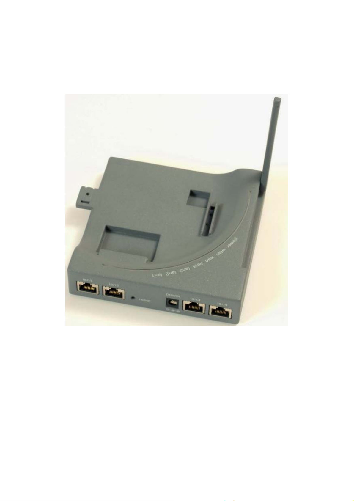
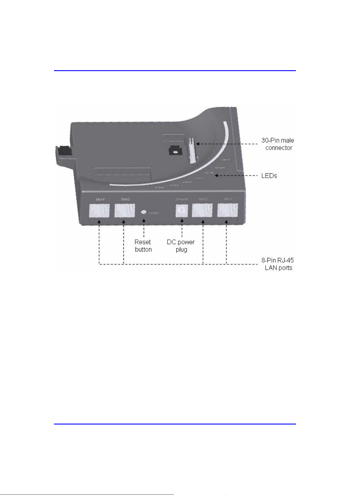
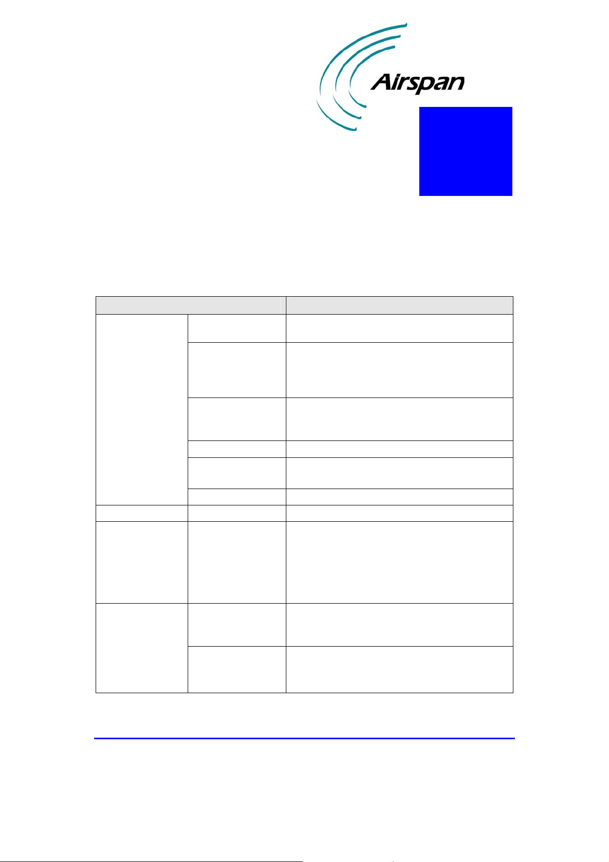
2.2. Ports
The EasyWiFi provides various ports on its side panel, as described in the table
below:
Table 2-2: Easy WiFi port description s
Port Label Interface
8-pin RJ-45 (x four) lan1, lan2, lan3, lan4 10/100BaseT Ethernet LAN
DC power jack
Reset button
30-pin IDC socket -- Interfaces with EasyST, providing:
power
reset
6 VDC power (supplied by AC/DC power
adapter)
Resets configuration settings to factory
default
• 802.11 Wi-Fi
• LAN switches
• DC power
(Note: IDC socket accepts flat cables)
18120511-01 Airspan Networks Inc. 2-2
Page 14
EasyWiFi Physical Description
Figure 2-1 display the EasyWiFi ports.
Figure 2-1: EasyWiFi ports (side and top panels)
18120511-01 Airspan Networks Inc. 2-3
Page 15
EasyWiFi Physical Description
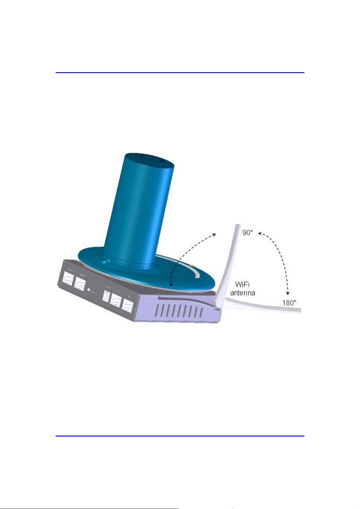
2.3. WiFi Antenna
The EasyWiFi provides an integral WiFi antenna located on its side panel that can
be orientated in the vertical pane, from 0° (i.e. antenna closed) to 180°. Two
positions are used: 90° when EasyWiFi mounted horizontally; and 180° when
EasyWiFi mounted vertically on a wall.
Figure 2-2: EasyWiFi integral WiFi antenna
18120511-01 Airspan Networks Inc. 2-4
Page 16

EasyWiFi Physical Description
2.4. Mounting Parts
The EasyWiFi unit provides built-in wall-mounting brackets, desktop-mounting feet,
as well as locking latches for mounting (attaching) the EasyST to the EasyWiFi
extension module.
Figure 2-3: EasyWiFi mounting parts (bottom panel)
18120511-01 Airspan Networks Inc. 2-5
Page 17

EasyWiFi Physical Description
2.5. LEDs
The EasyWiFi provides LEDs for indicating the status of various operations. These
LEDs are located on the top panel for easy viewing, as shown in the figure below:
Figure 2-4: EasyWiFi LEDs (top panel)
18120511-01 Airspan Networks Inc. 2-6
Page 18

EasyWiFi Physical Description
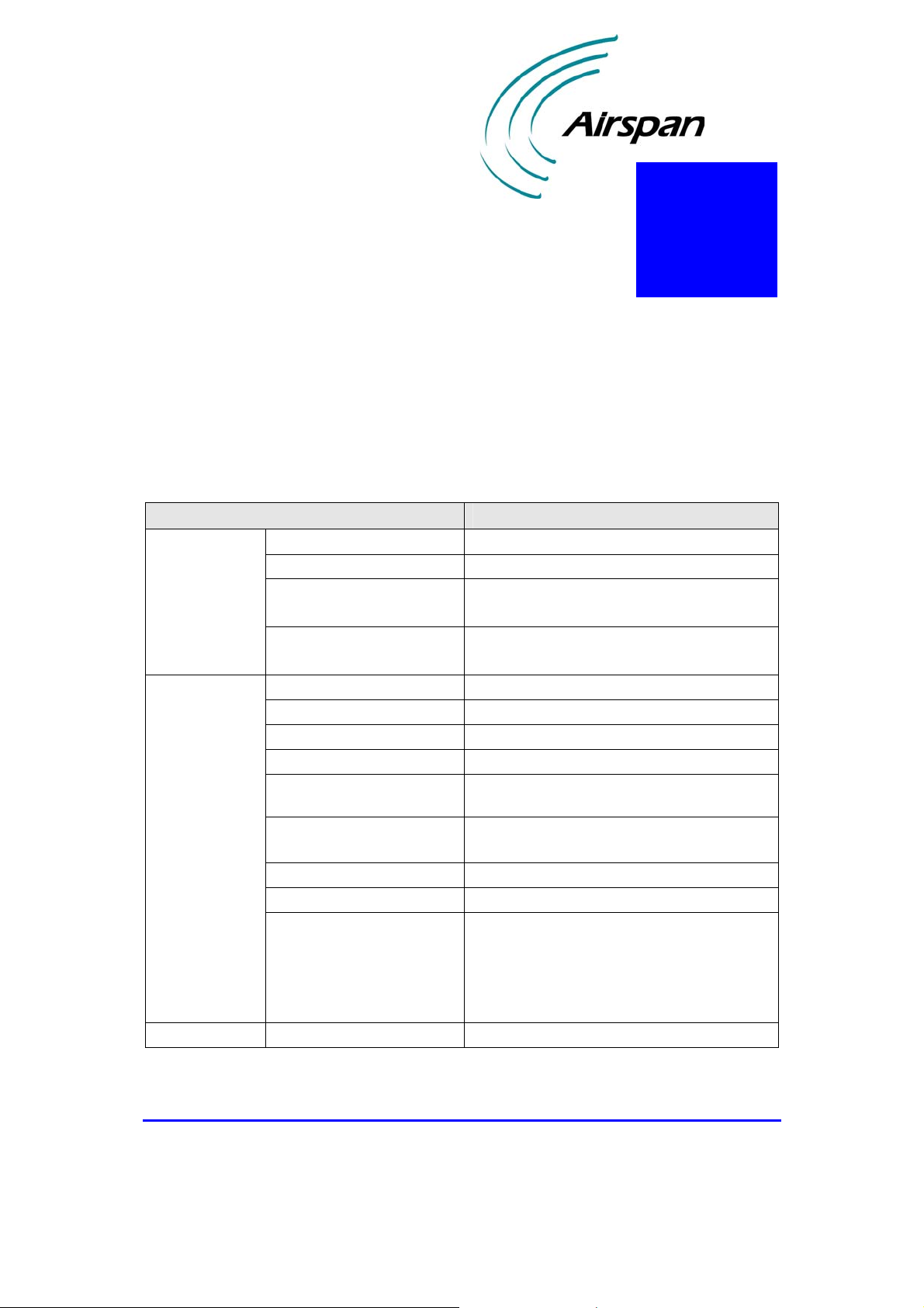
The EasyWiFi LEDs are described in the table below:
Table 2-3: EasyWiFi LED descriptions
LED Color Status Description
power Red
wlan Green
wan Green
lan1, lan2, lan3,
lan4
Green
On Unit receiving power
Flashing Unit is booting up
Off No power
On WiFi link with one user or more
Flashing Active WiFi link (i.e. data transfer)
Off No WiFi link
On Link (EasyST and EasyWiFi) is active
Flashing
Off EasyST is not connected
On
Flashing Active LAN link (i.e. traffic flow)
Off
Activity in 10Mbps - Blinks at 3Hz
Activity in 100Mbps – Blinks at 12 Hz
10/100BaseT network device (e.g. PC) is
on
No 10/100BaseT interface connected to
port
18120511-01 Airspan Networks Inc. 2-7
Page 19

EasyWiFi Physical Description
This page is intentionally left blank.
18120511-01 Airspan Networks Inc. 2-8
Page 20

3
Attaching EasyST
The EasyWiFi interfaces with the EasyST by means of a 30-pin connector, located
on the EasyWiFi's top panel.
For securing the connection of the EasyST to the EasyWiFi, the EasyWiFi provides
two latches that locks and unlocks the EasyST from the EasyWiFi. The latches are
located on the EasyWiFi's bottom and side panels.
Figure 3-1: EasyST attached to EasyWiFi
18120511-01 Airspan Networks Inc. 1
Page 21

EasyWiFi Attaching EasyST
To attach the EasyST to the EasyWiFi:
1. Align the EasyST with the EasyWiFi by aligning the following:
EasyST 30-pin female connector with EasyWiFi's 30-pin male
connector
EasyST RJ-45 port with EasyWiFi RJ-45 port labeled lan2
2. Press the EasyST firmly onto the EasyWiFi so that the 30-pin connectors
contact and plug into one another.
Figure 3-2: Aligning EasyST with EasyWiFi
18120511-01 Airspan Networks Inc. 3-2
Page 22

EasyWiFi Attaching EasyST
3. Lock the EasyST to the EasyWiFi using the two latches:
a. On the bottom panel, use your thumb to push the latch towards the
locking direction (indicated by the "lock" label).
b. On the bottom-side panel, use a tool with a pointed edge to move the
latch into the EasyST's mounting bracket by inserting the pointed
egde into the latch's hole, and then dragging the latch into the
EasyST's mounting bracket until it is firmly in place.
Figure 3-3: EasyWiFi latches (unlock position)
18120511-01 Airspan Networks Inc. 3-3
Page 23

EasyWiFi Attaching EasyST
Figure 3-4: EasyWiFi latches (lock position)
18120511-01 Airspan Networks Inc. 3-4
Page 24

4
Connecting to LAN
EasyWiFi provides four 8-pin RJ-45 ports for 10/100BaseT (Fast Ethernet) interface
with the subscriber's network. These LAN ports are located on the back panel and
labeled lan1, lan2, lan3, and lan4. The LAN ports support Half and Full duplexing
mode, Auto-Negotiation, and Auto-MDIX.
The EasyWiFi-to-computer cable setup is listed below:
Cable: straight-through CAT 5 STP Ethernet cable
Connector: 8-pin RJ-45 at both ends
Connector pinouts:
Pin Function
1 Tx+
2 Tx3 Rx+
6 Rx-
To connect EasyWiFi LAN ports to the subscriber's Ethernet network:
1. Plug the Category 5 Ethernet cable into the desired EasyWiFi 8-pin RJ-45
port.
2. Plug the other end of the Category 5 Ethernet cable into your computer's
LAN port located at the back of your computer.
18120511-01 Airspan Networks Inc. 1
Page 25

EasyWiFi Connecting to LAN
The figures below illustrate the EasyWiFi-to-computer cable connection:
Figure 4-1: Connecting EasyWiFi to subscriber's LAN
18120511-01 Airspan Networks Inc. 4-2
Page 26

5
Mounting
Warning: The EasyWiFi is an indoor unit and therefore, must be mounted
indoors.
Warning: To prevent a fire hazard caused by overheating, do not place the
EasyWiFi on a carpeted surface where airflow is restricted.
EasyWiFi is a self-installable indoor unit, requiring no professional installation by a
technician.
EasyWiFi must be mounted indoors in a location that provides the following:
High quality RF reception with the Internet service provider (i.e. base
station)
Accessibility to subscriber's power supply and LAN network with regards to
cable lengths
Strong radio signal strength for the WiFi communication link between
EasyWiFi and the subscriber's WiFi computer
EasyWiFi can be mounted in the following ways, depending on the EasyST's
antenna configuration:
EasyST with clip-on antenna: mounted horizontally on a desktop
EasyST with window-mount external antenna:
Mounted horizontally on a desktop
Mounted vertically on a wall
18120511-01 Airspan Networks Inc. 1
Page 27

EasyWiFi Mounting
5.1. Desktop Mounting
The EasyWiFi offers quick-and-easy mounting by allowing you to simply place it
horizontally on a desktop (as shown in the figure below). The EasyWiFi contains
integrated rubber feet (pads) on its bottom panel, providing cushioning as well as
insulation from static electricity.
Figure 5-1: Desktop mounting EasyWiFi
18120511-01 Airspan Networks Inc. 5-2
Page 28

EasyWiFi Mounting
5.2. Wall Mounting
When EasyST implements the window-mount, external antenna (i.e. no clip-on
antenna), the EasyWiFi can be mounted either on a desk (i.e. desktop mounting) or a
wall.
The figure below shows a wall-mounted EasyWiFi. The EasyST is connected to an
RF cable that connects to the external antenna (i.e. clip-on antenna is removed). For
mounting to a wall, the EasyWiFi provides two mounting hooks molded into its
bottom panel, as shown below:
Figure 5-2: Wall-mounted EasyWiFi
Note: The EasyWiFi's WiFi antenna must be fully extended (i.e. 180 degrees)
when wall mounted.
18120511-01 Airspan Networks Inc. 5-3
Page 29

EasyWiFi Mounting
To wall mount the EasyWiFi:
1. On the wall, mark the position with a pencil where you want to drill the two
holes for the screws onto which the two EasyWiFi mounting hooks will later
by guided. The distance between the two wall-mounting hooks (from their
centers) is approxiamtely 83 mm (3.27 inches). Ensure that the holes are
aligned and level using a spirit level.
2. Drill holes for each hole that you marked in the step above using a no. 6
twist-drill bit.
3. Tap the 6-mm wall anchors (supplied) into each of the drilled holes.
18120511-01 Airspan Networks Inc. 5-4
Page 30

EasyWiFi Mounting
4. Drive the two 0.75-inch screws (supplied) into the wall anchors. Ensure that
at least 0.08-inch gap is exposed between the screw head and the wall anchor
to allow insertion into the EasyWiFi mounting hooks.
5. Align the screws with the entrance to the two EasyWiFi mounting hooks, and
then pull down the EasyWiFi to lock the screws into the mounting hooks.
Figure 5-3: Inserting screws into wall mounting hooks
18120511-01 Airspan Networks Inc. 5-5
Page 31

EasyWiFi Mounting
This page is intentionally left blank.
18120511-01 Airspan Networks Inc. 5-6
Page 32

r
6
Connecting Power
EasyWiFi is powered by an AC/DC power supply adapter, supplying 6 VDC and 4
Amperes. The AC/DC adapter is plugged into a standard electrical wall outlet
(110/240 VAC; 50/60 Hz).
The power adapter also provides interchangeable prongs (e.g. American vs.
European) that can be replaced to suit country electrical standards in which the
EasyWiFi is being installed. To view the AC/DC power adapter specifications, see
Appendix C, "Power Adapter Specifications".
Note: Any AC/DC power adapter complying with Class 2 and LPS, and safety
approved according to national regulations, and that provides rated input of
100-240 V, 50/60 Hz, 0.4 A and output of 6 V, 4 A DC, may be used fo
powering the EasyWiFi.
18120511-01 Airspan Networks Inc. 1
Page 33

EasyWiFi Connecting Power
6.1. Changing the AC/DC Power Adapter's
Prongs
The AC/DC power adapter provides interchangeable prongs to suit electrical wall
outlet sockets in the country in which the EasyWiFi is being installed.
To change the plug prongs:
1. Remove the prongs by first moving (with the help of a pen) the
LOCK/OPEN switch to OPEN position, and then gently sliding the prongs
upwards, away from the power cord.
2. Align the desired prongs with the adapter's prong groove, and then slide the
prongs onto the adapter in the orientation as shown in the Figure 6-1. Ensure
that the prongs reach the end of the prong groove.
Figure 6-1: Replacing AC/DC power adapter plug prongs
3. Secure the prong in place by moving (with the help of a pen) the
LOCK/OPEN switch to LOCK position.
18120511-01 Airspan Networks Inc. 6-2
Page 34

EasyWiFi Connecting Power
6.2. Connecting AC/DC Power Adapter
Once you have attached the plug prongs suitable to your country's electrical wall
socket, you are ready to connect the EasyWiFi to the electrical wall outlet.
To connect the EasyWiFi to the power supply:
1. Before plugging the power cord into the electrical wall outlet, plug the
AC/DC power adapter's power cable (i.e. DC power jack) into the
EasyWiFi's DC power socket (labeled power).
2. Plug the prongs of the AC/DC power adapter into the electrical wall outlet.
Figure 6-2: Connecting DC power to EasyWiFi
18120511-01 Airspan Networks Inc. 6-3
Page 35

EasyWiFi Connecting Power
This page is intentionally left blank.
18120511-01 Airspan Networks Inc. 6-4
Page 36

7
Resetting EasyWiFi
The EasyWiFi provides a button that enables you to reboot the EasyWiFi as well as
reset the EasyWiFi settings to default. This button is located on the EasyWiFi's back
panel and labeled reset.
To reboot or reset to default the EasyWiFi:
1. Using a tool with a pointed edge, insert the edge into the hole labeled reset
(located on the back panel next to the DC power jack).
Figure 7-1: Resetting EasyWiFi to default using reset button
18120511-01 Airspan Networks Inc. 1
Page 37

EasyWiFi Resetting EasyWiFi
2. Push the the tool into the hole until you feel a button being pushed.
To reboot the EasyWiFi: push the button once and then remove the
tool
To reset the EasyWiFi to default settings: keep the button pressed
for at least 7 seconds
18120511-01 Airspan Networks Inc. 7-2
Page 38

A
FCC Interference Statement
Federal Communication Commission Interference Statement
This equipment has been tested and found to comply with the limits for a Class B
digital device, pursuant to Part 15 of the FCC Rules. These limits are designed to
provide reasonable protection against harmful interference in a residential
installation. This equipment generates, uses and can radiate radio frequency energy
and, if not installed and used in accordance with the instructions, may cause harmful
interference to radio communications. However, there is no guarantee that
interference will not occur in a particular installation. If this equipment does cause
harmful interference to radio or television reception, which can be determined by
turning the equipment off and on, the user is encouraged to try to correct the
interference by one of the following measures:
Reorient or relocate the receiving antenna.
Increase the separation between the equipment and receiver.
Connect the equipment into an outlet on a circuit different from that
to which the receiver is connected.
Consult the dealer or an experienced radio/TV technician for help.
This device complies with Part 15 of the FCC Rules. Operation is subject to
the following two conditions: (1) This device may not cause harmful
interference, and (2) this device must accept any interference received,
including interference that may cause undesired operation.
FCC Caution: Any changes or modifications not expressly approved by the
party responsible for compliance could void the user's authority to operate
this equipment.
IMPORTANT NOTE:
FCC Radiation Exposure Statement:
18120511-01 Airspan Networks Inc. A-1
Page 39

EasyWiFi FCC Interference Statement
This equipment complies with FCC radiation exposure limits set forth for an
uncontrolled environment. This equipment should be installed and operated with
minimum distance 20cm between the radiator & your body.
This transmitter must not be co-located or operating in conjunction with any other
antenna or transmitter.
18120511-01 Airspan Networks Inc. A-2
Page 40

B
Glossary
BS Base station
BWA Broadband wireless access
dB Decibel
dBm Power ratio in dB (decibel) of the measured power referenced to one
milliwatt
FTP File Transfer Protocol
GHz Gigahertz. One GHz represents 1 billion cycles per second
GW Gateway
HTTP HyperText Transfer Protocol
Hz Hertz
IP Internet protocol
ISP Internet Service Provider
LAN Local-Area Network
MAC The next layer up from the PHY, known as the media access
controller
Mbps Megabits per second (one million bits per second)
MHz Megahertz (one million cycles per second)
MIB Management information base
ODU Outdoor unit associated with an ST
QAM Quadrature amplitude modulation
QoS Quality of service, which is used to specify level of data throughput
18120511-01 Airspan Networks Inc. B-1
Page 41

EasyWiFi Glossary
RF Radio frequency
Rx Receive
SNMP Simple network management protocol
SNR Signal-to-noise ratio
ST Subscriber terminal (interchangeable with CPE)
SW Software
Tx Transmit
VoIP Voice over Internet protocol
WiFi Wireless Fidelity
WiMAX WiMAX is a wireless industry coalition whose members are
organized to advance IEEE 802.16 standards for broadband wireless
access (BWA) networks
18120511-01 Airspan Networks Inc. B-2
Page 42
C
EasyWiFi Specifications
The EasyWiFi specifications are listed in the table below:
Table B-1: EasyWiFi specifications
Parameter Value
Radio technology
Networking Working modes
Interfaces
Compliancy
Frequency
operation
Wireless
modulation
WiFi protocols
WiFi antenna
Clients
Tx power max.
WiFi
Safety
2412-2472 MHz
• (IEEE802.11g) Orthogonal Frequency
Divisional Multiplexing (OFDM)
• (IEEE802.11b) Direct Sequence Spread
Spectrum (DSSS)
• IEEE 802.11b
• IEEE 802.11g Japanese Standard ARIB STD-
T66
Gain: 1 dBi
• No. of concurrent assigned users: 1,024
• No. of concurrent active users: 32
19 dBm
Bridge (default) and IP router modes
• Four 10/100BaseT Ethernet LAN (support
Half/Full duplexing, Auto-Negotiation, AutoMDIX) with subscribers network Radio with
EasyST (30-pin IDC connector)
• DC power
• Default reset button
• WiFi certified: FCC Part 15 ClassA; WiFi;
WPA, WPA2
• 802.11 b/g
• Underwriters Laboratories (UL) 60950 (USA)
• IEC 60950 (International)
• EN 60950 (ETSI)
18120511-01 Airspan Networks Inc. C-1
Page 43

EasyWiFi EasyWiFi Specifications
Parameter Value
ETS 300 019 (ETSI)
EN 301489 (ETSI) FCC Part 15 Sub Class B
• FCC Part 15 15.247- 2.4 GHz
• EN 300 328 2.4 GHz
• TELEC STD-33/STD-66 (Japan/Telec)
SNMP and Web-based (HTTP)
Via TFTP server (using Web-based tool)
0 – 50°C ambient
-20 to +75°C ambient
15 - 90% RH
5 - 95% RH
• WiFi antenna
• 4 x 8-pin RJ-45 Ethernet LAN ports (Half/Full
duplexing, Auto-Negotiation, Auto-MDIX)
• DC power socket
• 30-pin IDC connector Button for reset
• LEDs for LAN, WAN, WiFi, Power
• 2 x wall-mounting brackets
• 2 locking clips for attaching EasyST
• Input Voltage / Amperage: 6V/4A
• Input Voltage Accuracy: ± 3% max. Ripple &
Noise: 100mVp-p max
Note: supplied by AC/DC adapter from 110/220
VAC outlet
30 x 125 x 125 mm
210 grams
Management
Environmental
Conditions
Mechanical
Environmental
EMC
Radio
WiFi/WiMAX
SW Upgrade
Operating
Temperature
Storage
temperatures
Operating
Humidity
Storage Humidity
Ports
Mounting
Power
requirements
Dimensions (H x W
x L)
Weight
18120511-01 Airspan Networks Inc. C-2
Page 44
D
Power Adapter
Specifications
The specifications of the AC/DC power adapter are listed in the table below:
Table C-1: AC/DC power adapter specifications
Parameter Value
Input
Output
General Efficiency
Input voltage
Input frequency
Input inrush current
Earth leakage
Output rating
Output voltage accuracy
Max. output power
Line regulation
Load regulation (full to
half load)
Transient response (full to
half load)
Temperature coeffeicient
Ripple and noise
Protections
90 to 264 VAC
47 to 63 Hz
• 30 A at 115 VAC
• 60 A at 230 VAC
• 0.4 mA max. @ 115 VAC
• 0.8 mA max. @ 230 VAC
6V / 4A
± 2% max.
24W
± 1% max.
6 ~6.5V
± 1% max. dev.
500 uS recovery
± 0.04% / °C
100mVp-p max
• Over voltage protection (output voltage
7.5V)
• Over power protection
• Short circuit protection
• Over current protection: 130% ~ 160%
70% typical at full load
18120511-01 Airspan Networks Inc. D-1
Page 45

EasyWiFi Power Adapter Specifications
Parameter Value
5 ms @ 115 VAC full load
VDE and FCC Class B limits
Input/output: 3000 Vac
Input/Ground: 1500 Vac
UL/CUL UL60950 CE EN55022
100 kHz
Input: interchangeable prongs
Output: DC power jack
1.25 m
86 × 46 × 33 mm
180 g
100,000 hours (MIL-HDBK-217F)
0 to +40°C
-20 to +85°C
5 to 95% RH non-condensing
2.4G, 5 to 500 Hz
Free air convection
Environmental
Hold-up time
EMI / RFI
Dielectric withstand
Safety meet
Switching frequency
Connector for radio
Cable length
Dimensions
Weight
MTBF
Operating temperature
Storage temperature
Humidity
Vibration
Cooling
18120511-01 Airspan Networks Inc. D-2
Page 46

EasyWiFi Power Adapter Specifications
This page is intentionally left blank.
18120511-01 Airspan Networks Inc. D-3
Page 47

How to find out
Airspan products
and solutions
more
about
For more information about
Airspan, its products and
solutions, please visit our
Web site:
www.airspan.com
Or write to us at one of the
addresses below.
We will be delighted to send
you additional
information on any of our
products and their
applications around the
world.
Airspan has offices in the
following countries:
Europe
Czech Republic
Poland
Russia
United Kingdom
Africa
South Africa
Americas
United States
Asia Pacific
Australia
China
Indonesia
Japan
New Zealand
Philippines
Sri Lanka
Worldwide Headquarters:
Airspan Networks Inc.
777 Yamato Road, Suite 105
Boca Raton, Florida 33431-4408
USA
Tel: +1 561 893 8670
Fax: +1 561 893 8671
Main Operations:
Airspan Communications Ltd.
Cambridge House, Oxford Road,
Uxbridge, Middlesex UB8 1UN
UK
Tel: +44 (0) 1895 467 100
Fax: +44 (0) 1895 467 101
 Loading...