

Page 1

1
Chapter 1 Product introduction
Table of Contents
1.1 Overview .................................................................................................... 1-4
1.1.1 High performance wireless technology ....................................................... 1-4
1.1.2 Good reliability and design optimization ..................................................... 1-5
1.1.3 Robust design for industrial hardware........................................................ 1-5
1.1.4 Product profile and dimensions ................................................................. 1-5
1.2 LED indicator .............................................................................................. 1-6
1.3 Installation ................................................................................................ 1-6
1.3.1 DIN-rail mounting .................................................................................. 1-6
1.3.2 Wall mounting ....................................................................................... 1-7
1.3.3 Wiring the redundant power input ............................................................. 1-8
1.3.4 Wiring the Alarm Contact ........................................................................ 1-8
1.3.5 Wiring the Digital Input ........................................................................... 1-9
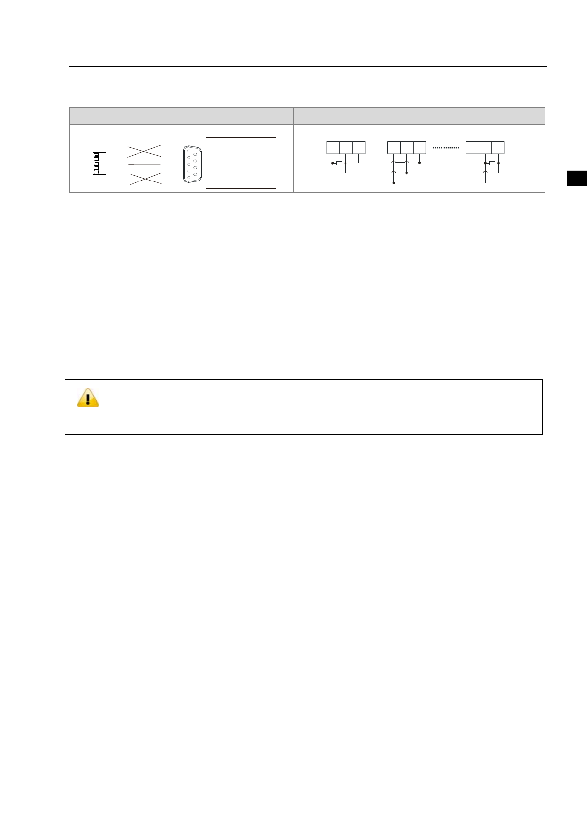
1.3.6 Pin definition ....................................................................................... 1-10
1.3.7 Wiring ................................................................................................ 1-11
1.4 Package checklist ..................................................................................... 1-11
1-1
Page 2

_
1
Delta Industrial Wireless DVW-W01I2-E1 Series User Manual
About this Manual
This manual contains information about DVW-W01I2-E1 series. When using Delta DVW series produ ct in
China, please refer to Delta official website with model
name DVW-W01I2-E1 or contact our nearest branch offices or distributors for furthe r information.
FCC Interference Statement
This equipment has been tested and found to comply with the limits for a class A digital device, pursuant to part 15 of the
FCC Rules. These limits are designed to provide reasonable protectio n ag ainst harmful interference in a residential
installation.
This equipment generates radio frequency signal and, if not installed an d used in accordance with the instructions, may
cause harmful interference to radio communications. However, there is no guarantee that interference will not occur in a
particular installation. If this equipment does cause harmful interference to rad io or television reception, which can be
determined by turning the equipment off and on, the user is encouraged to try to correct the interference by one or more of
the following measures:
---Reorient or relocate the receiving antenna.
---Increase the separation between the equipment and receiver.
---Connect the equipment into an outlet on a circuit different from that to which the receiver is connected.
---Consult the dealer or an experienced radio/TV technician for help.
CE Declaration of Conformity
The DVW series switches are CE certificated products, they could use in any kind of the environments under CE
environment specification. For keeping more safe application, we strongly suggest to use the CE-compliant industr ial
enclosure products.
Test Items:
EN 300 328
EN 301 893
EN 301 489-1/-17 for WLAN
EN 55032+EN 55024
EN 61000-6-4+EN 61000-6-2
EN 55011
EN 50385
Disclaimers and Limitation of Liabilities
To the maximum exte nt permitted by law and regardless DELTA be aware or has been advised of the possibilit y of these
damages, DELTA is not liable to any user or anyone else for: (a) any loss of use, data, reputation, goodwill, credit,
opportunity, economy or profits, whether or not foreseeable; (b) any special, incidental, indirect, consequential, or punitive
damages whatsoever; (c) any losses or damages based on any theory of liability, including breach of contract or warranty,
negligence or other tortious action; (d) any losses or damages resulting from use or unable to use the systems or devi ces
to which the Software or Services are incorporated or co-operated; and (e) any losses or damages arising from any other
1-2
Page 3
_
claim or in connection with the use of or access to the Software or Services.
Warning
Chapter 1 Product introduction
此设备应安装在限制进出的场所。限制进出场所指仅能透过特殊工具、锁和钥匙或
其他安全手段才能进出的场所。
This equipment should be installed in a place wh ere access is restricted.
Restricted places are places that can only be accessed through special tools,
locks and keys or other security means.
在接近热源部分的明显位置上会有警告标示。
There will be a warning sign in an obvious position near the heat source part
Warning
Supplied by LPS power source
1
1-3
Page 4
_
1
Delta Industrial Wireless DVW-W01I2-E1 Series User Manual
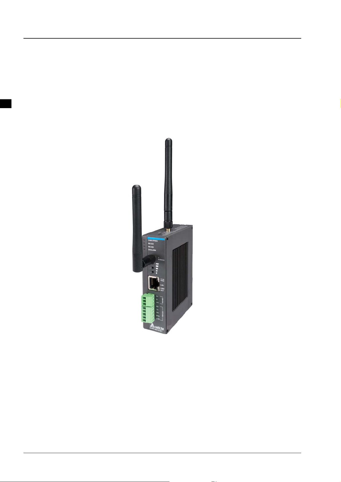
1.1 Overview
Delta’s industrial wireless DVW-W01I2-E1 series features Ethernet port, RS-232 and RS-485, supports
standard MODBUS protocol for executing and controlling data transmission with operating devices.
DVW-W01I2-E1 supports fast-roaming solution especially suitable for clients in wireless environment to
quickly switch connection from one AP to another for continuous roaming experience and applications, such
as automatic storage system or autonomous carriers.
1.1.1 High performance wireless technology
10/100/1000/Base-T
Auto detects transmission speed
Auto-MDI/MDI-X
802.11 a/b/g/n/ac, up to 866 Mbps
Supports fast roaming (personal network)
1-4
Page 5
Chapter 1 Product introduction
_
5
1.1.2 Good reliability and design optimization
Redundant dual DC power input
One set of digital input (DI)
One set of alarm output (DO)
1.1.3 Robust design for industrial hardware
Operating temperature: -10~60℃
Storage temperature: -40 ~ 85℃
Humidity: 5%~95% (non-condensing)
Metal case: IPX0
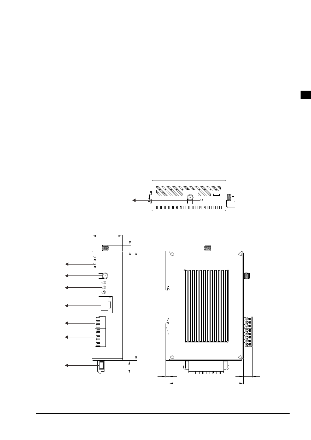
1.1.4 Product profile and dimensions
1
31
6
110
13.5
3.4 8.9
7
Unit = mm
1-5
Page 6
Delta Industrial Wireless DVW-W01I2-E1 Series User Manual
_
1
No
1 LED indicator
2 Antenna socket
3 Signal strength
Ethernet port
4
RS-485 port
5
RS-232 port
6
Power terminal
7
Reset button
8
1.2 LED indicator
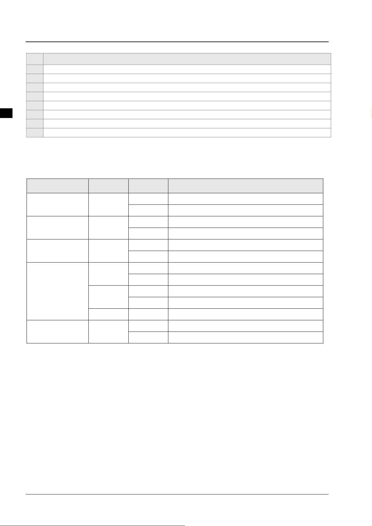
LED Color Status Description
PWR1/PWR2
RS-232
Green
Green
Description
On The device is powered up
Off The device is not powered up
Blinking Data transmission
Off No data transmission
RS-485
DI/ALARM
Green
Red
Blinking Data transmission
Off No data transmission
On Closed relay
Off Disconnect relay
On V alid digital input (DI)
Green
Off No digital input (DI)
Blinking Relay closed and DI occurs simultaneously
Signal light
Green
On Lighting 1-3 lights based on signal strength
Off No network signal
1.3 Installation
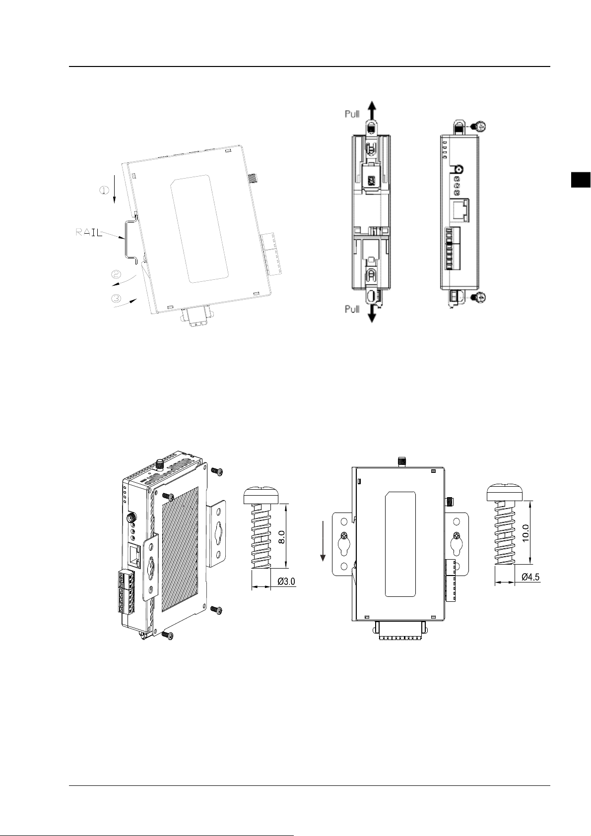
1.3.1 DIN-rail mounting
Attach the back trench of the device to the mounting rail in arrow ① direction and push the device against the
rail in arrow ② direction. To disassemble, first push down the device in arrow ① direction and follow arrow
③ direction to push out the device.
1-6
Page 7
Chapter 1 Product introduction
_
1
1.3.2 Wall mounting
1-7
Page 8
_
1
Delta Industrial Wireless DVW-W01I2-E1 Series User Manual
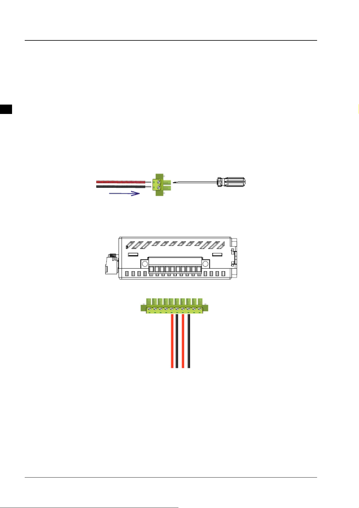
1.3.3 Wiring the redundant power input
The DVW-W01I2-E1 is equipped with one to two sets of DC input (PWR1 / PWR2). Both sets of DC input can
be connected to a wide range of power sources (12 to 48VDC). When one power source fails, the other
source can work as a backup to ensure that the machine operates normally.
Step 1: Det ach the terminal block from
terminal block. Make sure that the positive DC wire is connected to V1+ or V2+, and that the negative DC wire
is connected to 0V.
Step 2: To prevent the loose DC wires, tighten the wire clamp screws on the terminal block with the flat-blade
screwdriver.
DVW-W01I2-E1 and insert the negative and positive DC wires into the
Note: Please use copper wire 60/75oC, AWG 28-14; screw torque is 2.2kgf-cm (1.91 in-lbs)
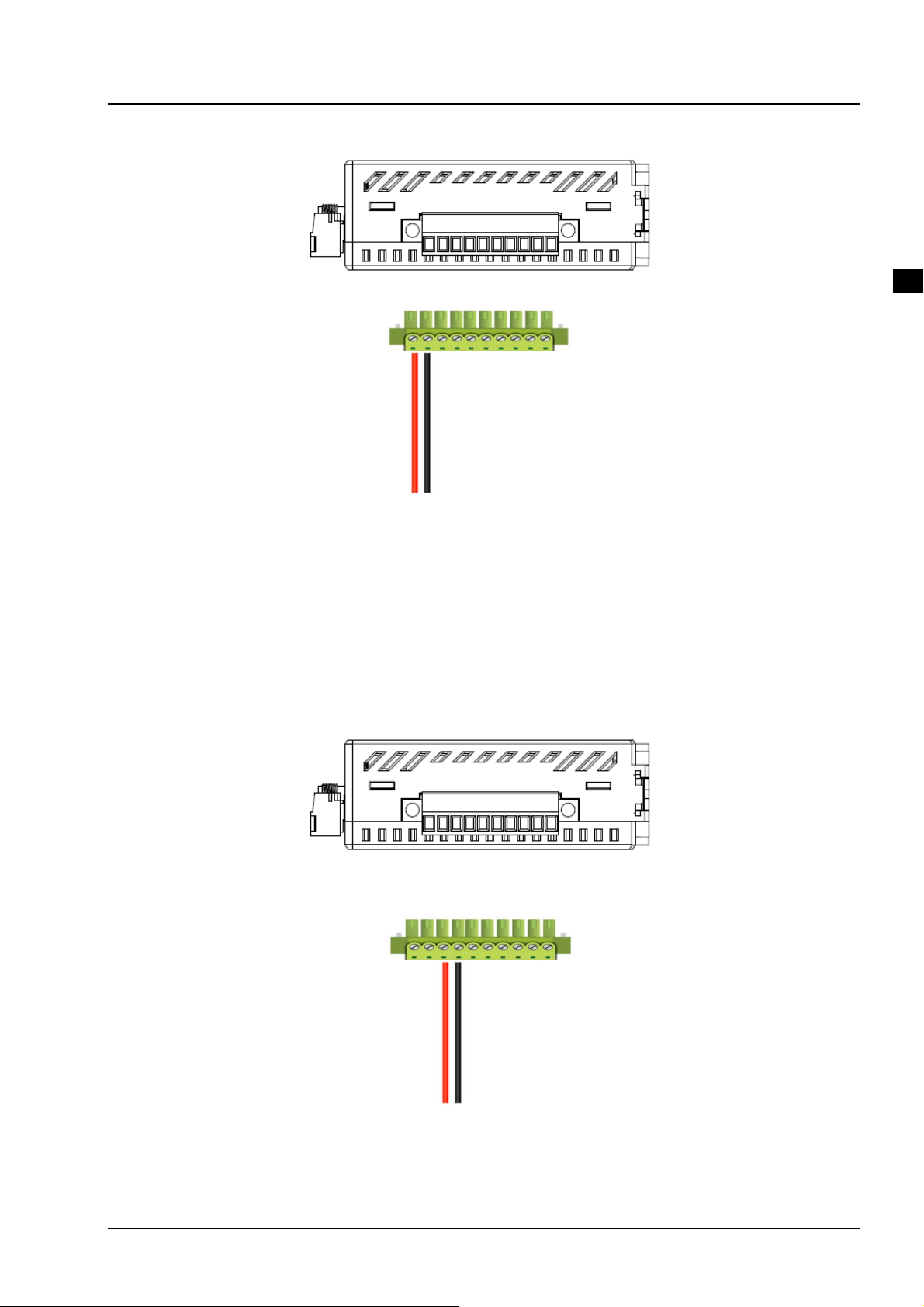
1.3.4 Wiring the alarm contact
The DVW-W01I2-E1 is equipped with one to two sets of alarm output. The alarm contact is a dry relay. Under
normal mode of operation, the contact is in “OPEN” circuit; when one of the two power sources fails or
communication is interrupted, the contact will change to a “CLOSED” circuit. The relay can be connected up
to 1A/24VDC power source.
1-8
Page 9
Chapter 1 Product introduction
_
1.3.5 Wiring the digital input
The DVW-W01I2-E1 is equipped with one to two sets of digital input. When input voltage is between 0 to 5V,
the state of DI is OFF; input voltage between 11 to 30V, the state of DI is ON. The maximum input current is
6mA.
1
1-9
Page 10
_
1
Delta Industrial Wireless DVW-W01I2-E1 Series User Manual
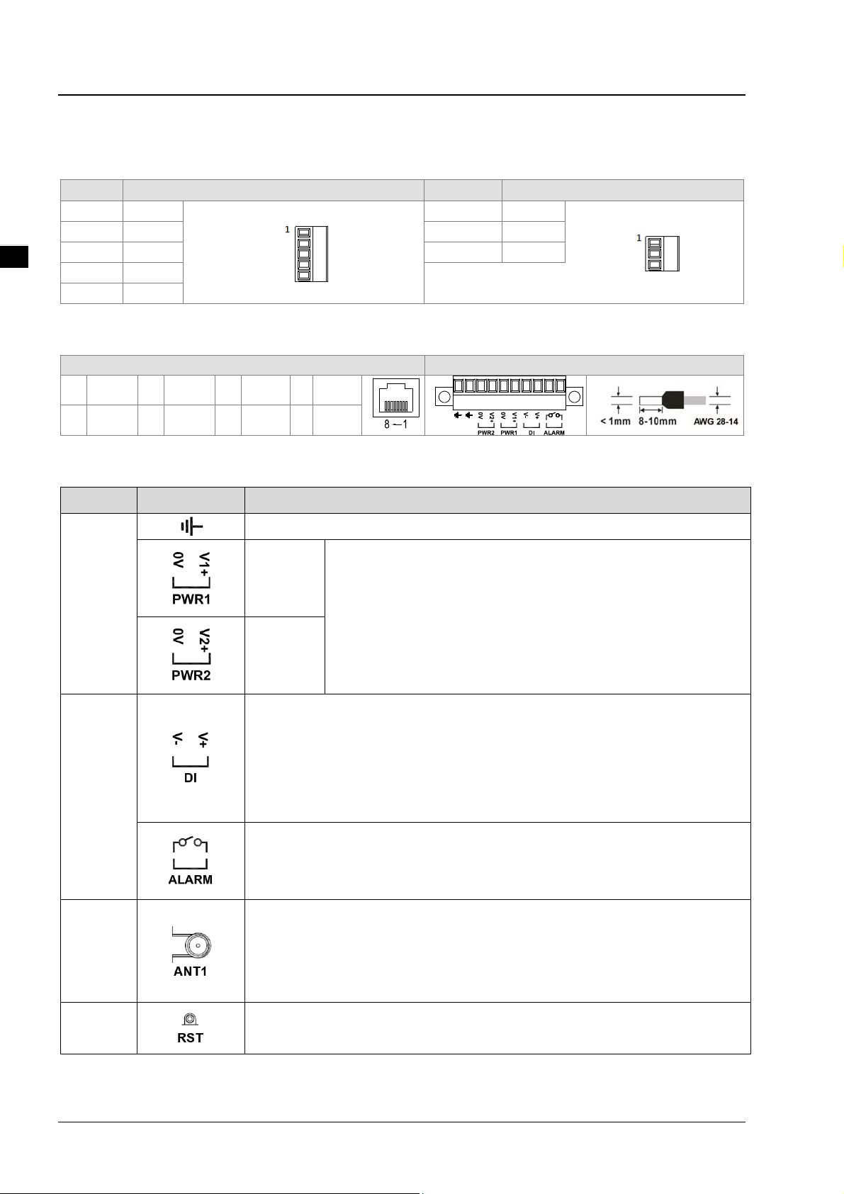
1.3.6 Pin definition
RS-232 & RS485
Pin no. RS-232 Pin no. RS-485
1 RX
2 TX 2 D3 SG 3 SG
4 RTS
5 CTS
1 D+
Ethernet port (RJ45) & power input
Ethernet port (RJ45) Power input
1 TX+ 2 TX- 3 RX+ 4 N/C
5 N/C 6 RX- 7 N/C 8 N/C
Interface
Category Terminal Explanation
Power
I/O
Power ground where two grounds interconnect
Power 1 Input voltage: DC 12V~24V, +/- 20%;
Power consumption in normal operation: 2.5W;
Power 2
DI:
Input type: DC (sourcing or sinking)
Input current: 24V:5ma
Max. input frequency: 1KHZ
Input impedance: 5.6K
DO:
Contact rating: DC24V: 2A, AC125V: 0.5A, AC220V: 0.2A
Reverse voltage protect;
Dual redundant power supply , the device will automatically
match to the higher voltage side and disconnect from the
lower voltage side
ANT1
RST
1-10
Wi-Fi antenna, external thread connector (male)
Internal diameter: 4.45mm
External diameter (thread excluded): 5.32mm
External diameter: 6.26mm
Press less than 3 seconds: restart the device
Press longer than 6 seconds: restore to default
Page 11
_
1.3.7 Wiring
s
t
o
deS
o
deS
o
d
RS-232 RS-485
RS-232
RX
TX
SG
RTS
CTS
RXD
TXD
GND
RTS
CTS
RS-232
12345
Termin al
resistor
(120 ohm )
Pin
1
6789
2
3
4
5
RXD
TXD
GND
Pin
6
7
8
9
RTS
CTS
-
1.4 Package checklist
The package contains the following accessories:
Delta industrial wireless DVW-W01I2-E1 series x1
Instruction sheet x1
SMA antenna x 2
Wall mount metal accessory x1
Chapter 1 Product introduction
Ma
er n
D+ D- SG D+ D- S G SG D+ D-
lave n
lave n
e
Terminal
resistor
(120 ohm)
1
Screws x4
Attention
Each released DVW-W01I2-E1 contains accesso ries that are listed above. Wh en you receive th e
product, please open the package and check for any missing or broke n accessories. For any
enquiries, do contact our local distributors.
1-11
Page 12

2
Chapter 2 User Interface
Table of Contents
Chapter 2 User Interface ..................................................................................................... 2-1
2.1 Configuration ................................................................................................................... 2-2
2.2 Connection and access settings ........................................................................................ 2-2
2.3 General configurations ..................................................................................................... 2-4
2.3.1 AP mode setup ........................................................................................................ 2-4
2.3.2 Client mode setup ................................................................................................... 2-6
2-1
Page 13
_
2
Delta Industrial Wireless DVW-W0 1I2-E1 Series User Manual
2.1 Configuration
Before using DVW-W01I02-E1 series, please pay attention to the following item preparation.
No Item Description
1
2
3
PC Contains Windows operating system and web browsers.
Power supply Supports 12-48V with output power larger than 2.5W.
Cable Includes 5 types of twisted pair as communication cables of DVW-W01I02-E1.
2.2 Connection and access settings
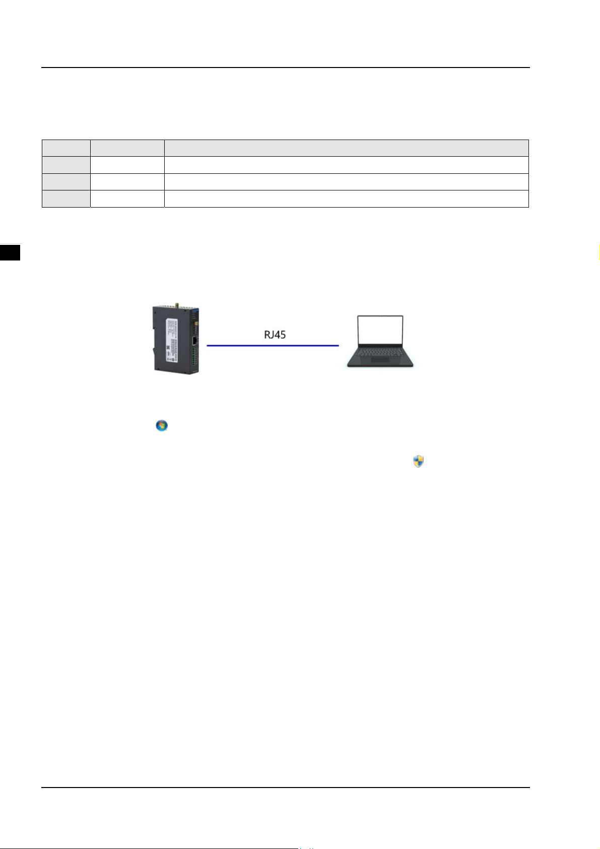
1. The DVW-W01I02-E1 series and PC connects to RJ45 port through using web-based Ethernet for
parameter settings.
2. When PC and DVW device connection is complete, continue configuring the PC’s IP address.
1) Click the start button
2) In Network and Sharing Center, check the network connections.
3) Right-click the connection for modification, then click Attribute. When the UAC
please type in the user password for confirmation.
4) Click Network. Under this option, select Internet Protocol Version 4 (TCP / IPv4) or Internet Protocol
Version 6 (TCP / IPv6), then click Attribute.
, then click the control panel to open network connection.
appears as a reminder,
2-2
Page 14
Chapter 2 User Interface
_
2
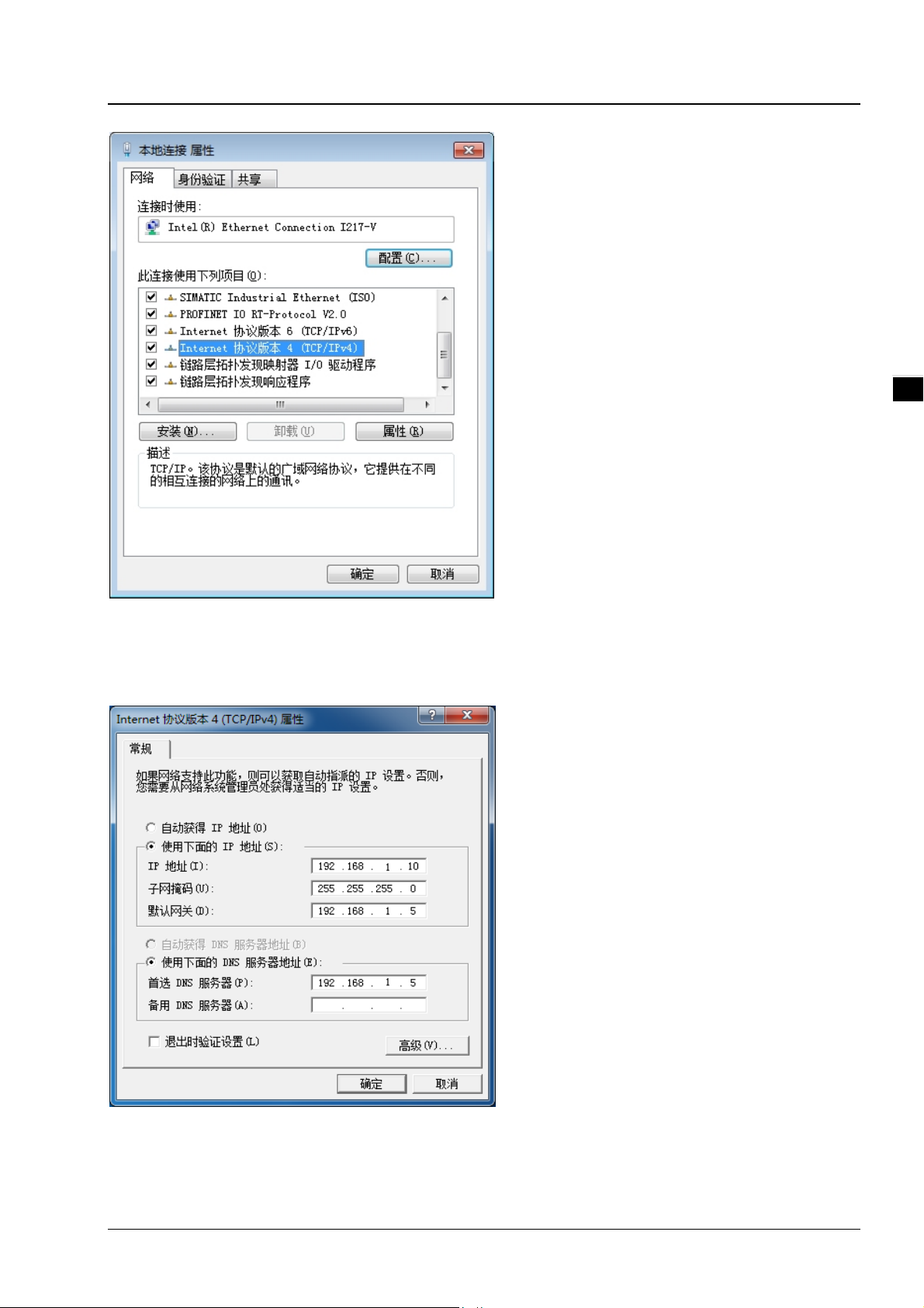
Manually configure the local IP address. Since the default IP address is 192.168.1.5 for router settings, the
subnet masks is 255.255.255.0, therefore, the local IP on PC can be set anywhere between 192.168.1.1 to
254 excluding 192.168.1.5 and with no repeating IPs. We setup the IP address as 192.168.1.10, the default
gateway is 192.168.1.5, select an available DNS address or configuring to 192.168.1.5.
2-3
Page 15
_
2
Delta Industrial Wireless DVW-W0 1I2-E1 Series User Manual
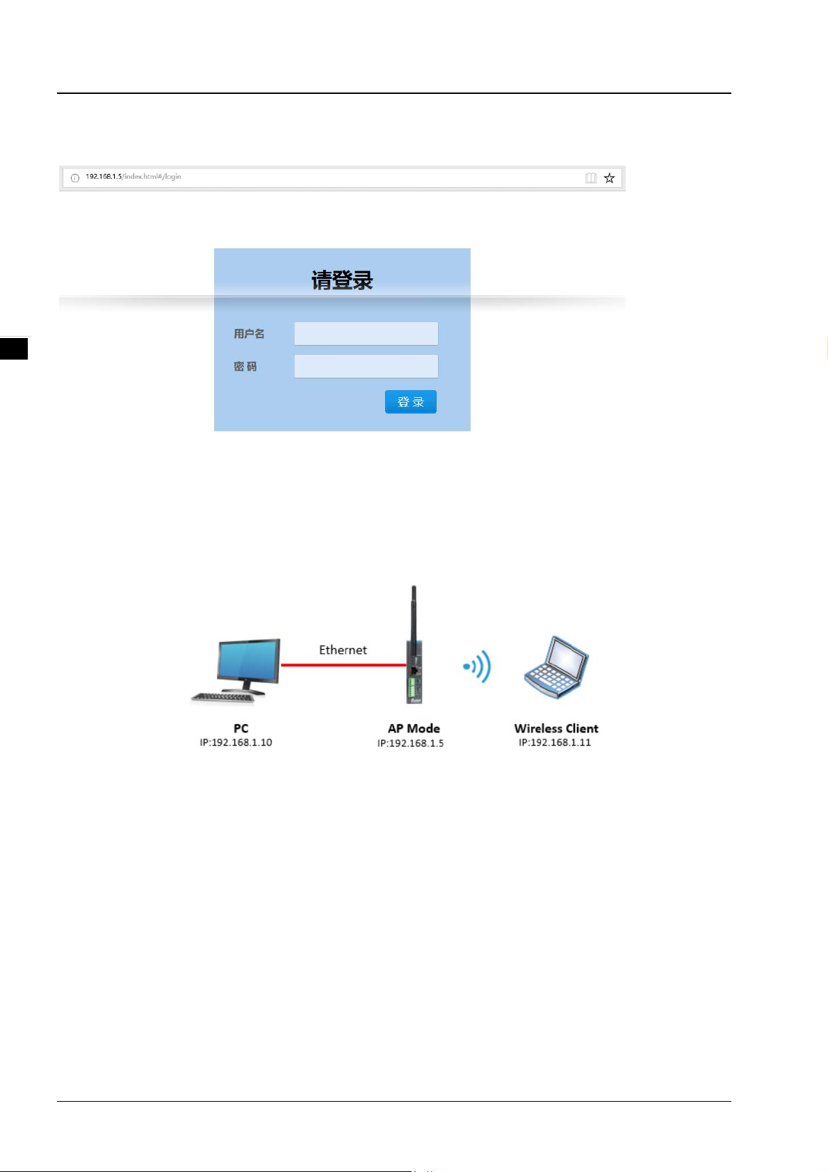
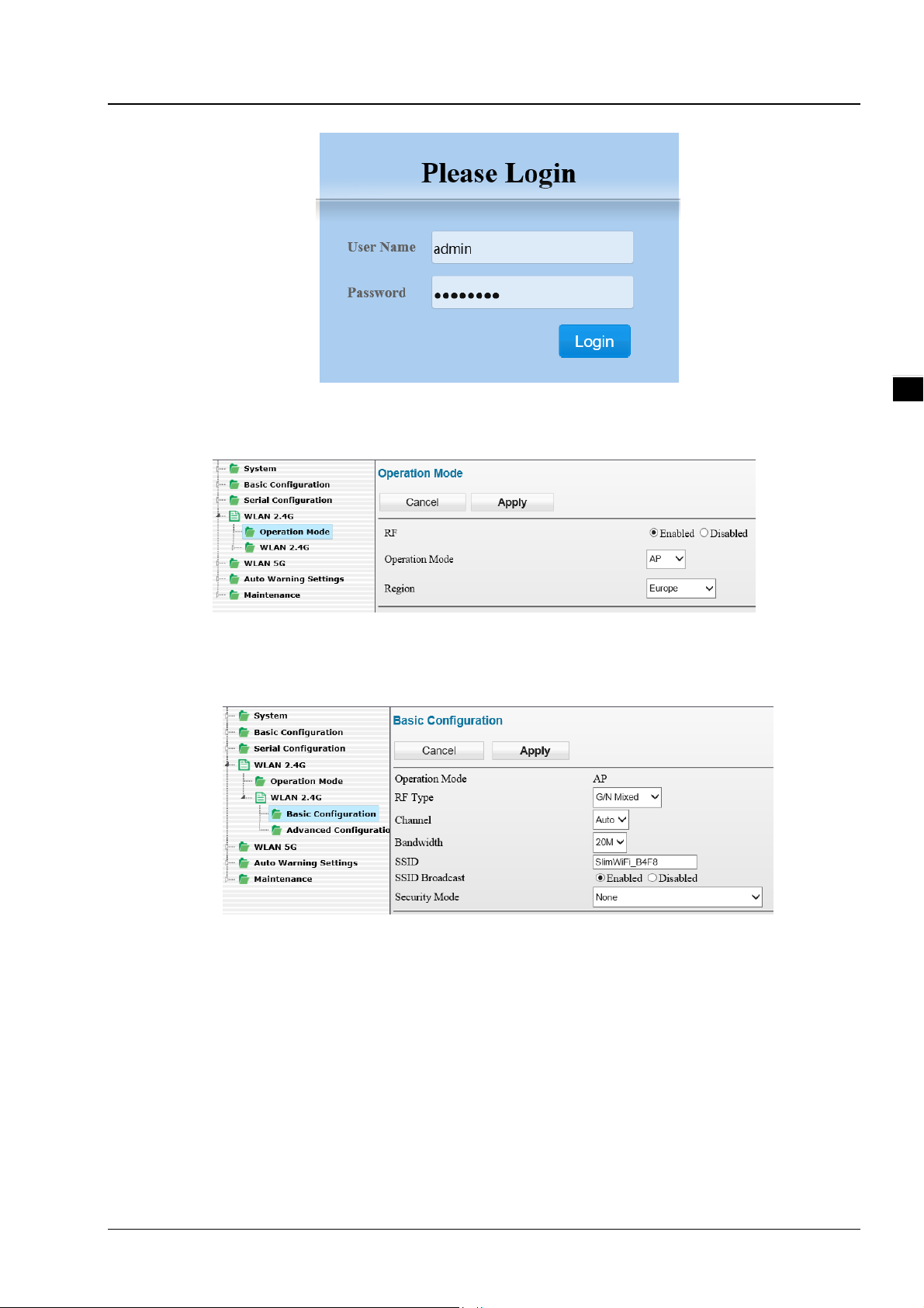
3. Open browser (e.g. IE) then type in default IP address 192.168.1.5 and click enter. The following log-in
page appears for users to enter the correct username and password (Default setting: admin/password).
2.3 General configurations
2.3.1 AP mode setup
In AP mode, the access point serves as intermediate point between devices for wired or wireless connection
and data transmission.
Configuration procedures
1. Set all IP addresses in the same segment.
2. Log in the DVW wireless device page on the PC, the default IP is 192.168.1.5. Username and password
by default is admin/password.
2-4
Page 16
Chapter 2 User Interface
_
3. From WLAN2.4G listed on the menu, select Operation Mode, choose AP mode and click Apply.
4. Select Basic Configuration and setup SSID name as well as WPA2-PSK for security mode
(recommended), then click Apply.
2
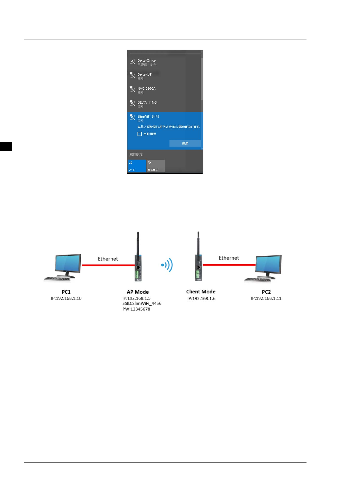
5. For wireless client, search for DVW SSID (SlimWiFi_B4F8) in the AP list and click to complete on-line
data transmission via wireless connection.
2-5
Page 17
_
2
Delta Industrial Wireless DVW-W0 1I2-E1 Series User Manual
2.3.2 Client mode setup
When users have two DVW devices, one uses AP mode and the other as client mode, both are combined via
wireless connection. However, only LAN connection can be used in client mode but not wireless devices or
connections.
Configuration procedures
1. Set all IP addresses in the same segment.
2. AP mode: please refer to section 2.3.1.
3. Client mode: Log in the wireless client device page on PC through default IP setting 192.168.1.6.
Username and password by default is admin/password.
2-6
Page 18
Chapter 2 User Interface
_
4. From WLAN2.4G listed on the menu, select Operation Mode, choose Client mode and click Apply.
5. Select Basic Configuration and click “Site Survey”.
2
6. Select the configured AP SSID (e.g. SlimWiFi_4456). When SSID cannot be found, please click
“Refresh”.
2-7
Page 19

_
2
Delta Industrial Wireless DVW-W0 1I2-E1 Series User Manual
7. Type in the password for AP setting and click APPly to complete Client and AP connection.
8. When connection is complete, select Ping under Maintenance. Then, type in destination IP to test the
connection. For successful connection, the AP Ping response time appears. (See below)
2-8
Page 20

3
Chapter 3 Function Guide
Table of Contents
System ....................................................................................................... 3-2
3.1
3.1.1 System configuration ................................................................................. 3-2
3.1.2 System CPU status .................................................................................... 3-2
3.2 Basic configuration ..................................................................................... 3-3
3.2.1 System information ................................................................................... 3-3
3.2.2 Network configuration ............................................................................... 3-4
3.3 Serial configuration .................................................................................... 3-5
3.3.1 MODBUS gateway ..................................................................................... 3-5
3.3.2 Serial server .......................................................................................... 3-12
3.3.3 Transparent server .................................................................................. 3-18
3.3.4 MODBUS cache table ............................................................................. 3-21
3.4 WLAN management - 2.4G ........................................................................ 3-25
3.4.1 Operation mode ...................................................................................... 3-25
3.4.2 WLAN 2.4G ............................................................................................ 3-25
3.5 WLAN management - 5G ........................................................................... 3-30
3.5.1 Operation mode ...................................................................................... 3-30
3.5.2 WLAN 5G ............................................................................................... 3-31
3.6 Auto alarm function .................................................................................. 3-35
3.6.1 Using relay for alarm system .................................................................... 3-35
3.7 Maintenance ............................................................................................. 3-36
3.7.1 Session timeout ...................................................................................... 3-36
3.7.2 Password ............................................................................................... 3-36
3.7.3 System log backup .................................................................................. 3-37
3.7.4 Roaming log ........................................................................................... 3-37
3.7.5 Serial log ............................................................................................... 3-38
3.7.6 Ping ...................................................................................................... 3-38
3.7.7 Ping detection ........................................................................................ 3-38
3.7.8 Firmware upgrade ................................................................................... 3-39
3.7.9 Configuration Import & Export .................................................................. 3-39
3.7.10Load factory default ................................................................................ 3-39
3.7.11Log off .................................................................................................. 3-40
3-1
Page 21
_
3
Delta Industrial Wireless DVW-W0 1I2-E1 Series User Manual
3.1 System
The main display focuses on DVW-W01I2-E1 series present system information and CPU status.
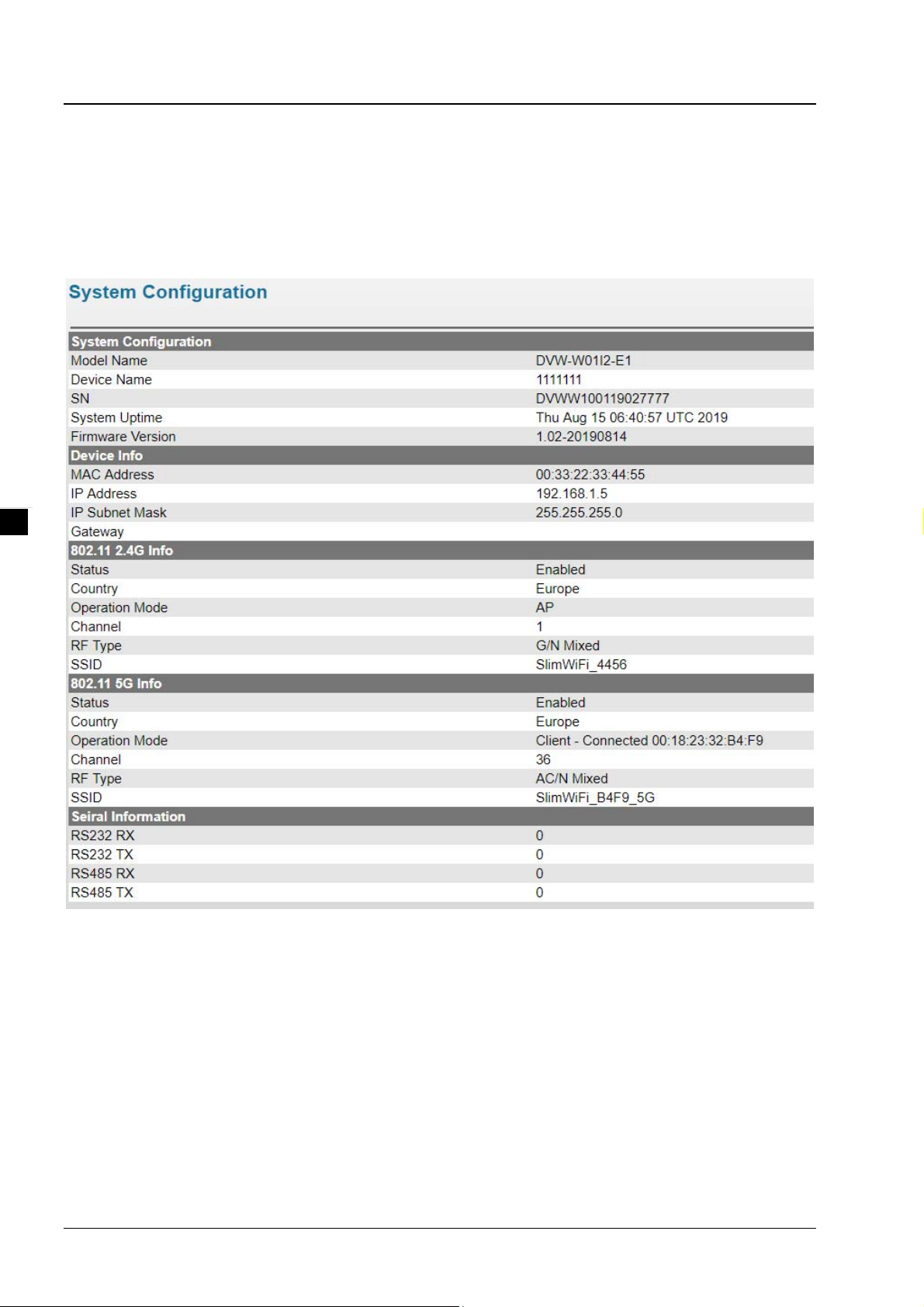
3.1.1 System configuration
Displays information which can be categorized into three parts: System Configuration, Device Info and 802.11
Info.
3.1.2 System CPU status
Displays system’s present CPU status which includes running time, total power-on time, CPU usage, total
RAM and RAM available. These status values are displayed in grey color and cannot be edited.
3-2
Page 22

Chapter 3 Function Guide
_
3.2 Basic configuration
The basic configuration allows users to perform maintenance and setup for DVW-W0 1I2-E1 series including
system information and network.
3.2.1 System information
The configuration contains user-defined device name, location, description and contact information. Through
this setup, users can easily and clearly identify each DVW-W01I2-E1 used on the network.
3
Description Default value
Device name
Users can define the device name DVW-W01I2-E1
Device location
Users can define the device location Europe
Device description
Users can provide detailed device description
Device contact information
Users can input contact information of maintenance personnel. NONE
Delta Dual-Band
WiFi Router
3-3
Page 23

Delta Industrial Wireless DVW-W0 1I2-E1 Series User Manual
_
3.2.2 Network configuration
Network configuration allows users to setup IP, IP address, IP subnet mask, gateway IP and primary DNS.
There are several IP modes available for network configuration. Users can select modes from DHCP-Client,
Static and DHCP-Server.
DHCP-Client:
Configure the network as DHCP-Client in DVW-W01I2-E1 series:
When DHCP server is added for installment, DVW-W01I2-E1 will use the IP address assigned by DHCP
server.
When DHCP server is not added for installment, DVW-W01I2-E1 will auto-configure the IP address to
192.168.1.5 and the IP subnet mask to 255.255.255.0.
Static:
Users can define the device regarding IP, IP address, IP subnet mask, gateway IP and primary DNS.
DHCP-Server:
When DHCP-Server is installed in DVW-W01I2-E1, DHCP-Server and BOOTP-Server are both enabled
and exist in this mode. The IP address is auto-configured to 192.168.1.5 and the IP subnet mask to
255.255.255.0. When end user devices and clients request for IP address, DVW-W01I2-E1 wi ll assign a
set of dynamic IP address.
3
The gateway IP address provided by DHCP server address pool is from 192. 168.1.100 to 192.168.1.250,
users are allowed to configure the starting and ending of the IP address pool.
Description Default value
IP
Allows different mode configuration, options include DHCP-Client,
Static and DHCP-Server
DHCP-Client: DVW-W01I2-E1 will use the IP setting from the
DHCP-Server.
Static: Manually setup the IP address
DHCP-Server: DHCP-Server and BOOTP-Server are both enabled
and exist in this mode, the DVW-W01I2-E1 will assign a set of
dynamic IP address to the end-user device.
IP address
Static
3-4
Page 24
Chapter 3 Function Guide
_
Description Default value
Configure IP address and identify DVW-W01I2-E1 series in TCP/IP
network.
IP subnet mask
Set the IP subnet mask of router LAN ports. (Example: 255.0.0.0 is
Type A address; 255.255.0.0 is Type B address; 255.255.255.0 is
Type C adderss)
Gateway IP
Connect DVW-W01I2-E1 to WAN IP gateway.
Primary DNS
Connect DVW-W01I2-E1 to primary DNS in WAN configuration that
translates domain names into IP addresses.
Starting IP address
The starting IP address provided by DHCP server address pool. 192.168.1.100
Ending IP address
The ending IP address provided by DHCP server address pool. 192.168.1.250
192.168.1.5
255.255.255.0
1 day
3.3 Serial configuration
DVW-W01I2-E1 contains MODBUS gateway, serial server and transparent transmission functions. The
MODBUS gateway function allows data to be transferred from MODBUS to Ethernet and vice versa. While
serial server and serial port transparent transmission modules can provide real-time networking to access
serial devices at any time or locations.
3.3.1 MODBUS gateway
MODBUS gateaway allows DVW device to perform format conversion and data transfer. (Convert Modbus
RTU/ASCII to Modbus TCP).
3.3.1.1 RS-485 gateway
MODBUS ASCII / RTU Slave
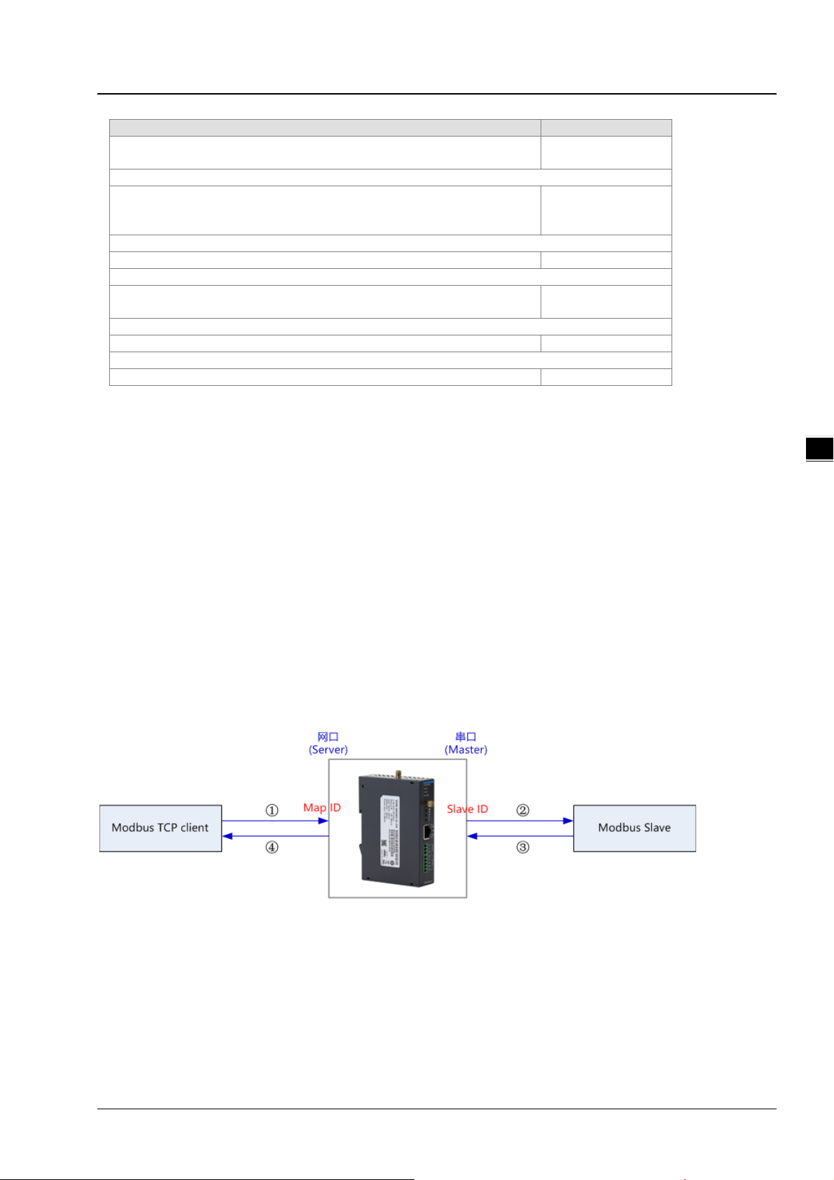
In this mode, the DVW series serve as MODBUS TCP server. When the device receives client’s MO DBUS
request, it is packed into MODBUS ASCII/RTU protocol and corresponding serial ports can be confirmed
base on the map ID. Also, MODBUS ASCII/RTU master can forward request to slave through DVW series.
3
For instance, RS-232 serial port slave ID setting range is 1-20, map ID setting ran ge 1-20; while RS-485 seri al
port slave ID setting range is 1-20 and map ID setting range is 21-40. When users request reading PLC
station number 6 data connected via RS-232 through MODBUS network port, the map ID needs to be
configured to 6; when reading PLC station number 6 data connected via RS-485 through MODBUS network
port, the map ID needs to be configured to 26.
3-5
Page 25

Delta Industrial Wireless DVW-W0 1I2-E1 Series User Manual
_
Attention
For RS-232 and RS-485, the configured map ID range cannot have repeated
regions, because the system forwards the request to serial ports base on the
network port of the map ID in the request data.
3
MODBUS ASCII / RTU Master
In this mode, the DVW series serve as MODBUS ASCII/RTU Slave. When the device receives master’s
MODBUS request, it is packed into MODBUS TCP protocol base on the station ID and the corresponding
relationship from the forward table. Also, MODBUS TCP client can forward request to the server through
DVW series.
3-6
Page 26

Chapter 3 Function Guide
_
3
3-7
Page 27

_
3
Delta Industrial Wireless DVW-W0 1I2-E1 Series User Manual
Description Default value
Operation mode
Select the roles and operating agreement for present network and serial ports via
following options:
1. MODBUS ASCII Slave: The network port for DVW device operates in MODBUS
TCP Server mode, the RS-485 serial port operates in MODBUS ASCII master
mode.
2. MODBUS RTU Slave: The network port for DVW device operates in MODBUS
TCP Server mode, the RS-485 serial port operates in MODBUS RTU master
mode.
3. MODBUS ASCII Master: The network port for DVW device operates in
MODBUS TCP client mode, the RS-485 serial port operates in MODBUS ASCII
slave mode.
4. MODBUS RTU Master: The network port for DVW device operates in MODBUS
TCP client mode, the RS-485 serial port operates in MODBUS RTU slave mode.
Data bit
Displays serial port data bit; the value is fixed to 7 in ASCII protocol,
Configuring
RS485
the value is fixed to 8 in RTU protocol.
Parity bit
Configuring parity for serial port. Optional values include “none”, “odd”
or “even”.
Stop bit
Close
N/A
None
3-8
Page 28
_
Configuring stop bit for serial port. Optional values include 1 or 2. 1
Baud rate
Configuring baud rate for serial port. Optional values include 2400,
4800, 9600, 19200, 38400, 57600, 115200.
Station ID
Displays the station ID of the device. The station ID of RS-485 is 247. N/A
TCP keepalive time
Configure DVW device in idle TCP connection to setup TCP
keep-alive time. When the time is “0”, the connection will stay open.
Others
Slave mode
Master
mode-
Forward
table
3.3.1.2 RS-232 gateway
Response timeout
DVW device waits for serial port response timeout. 3000
Retry
Setup the number of retry when response time reaches timeout. 3
MODBUS exception
When device reaches response timeout, exception code may be sent
to client.
Mapping slave ID
Setup slave ID mapping table.
-- Slave ID range: Input actual station ID range.
-- Map ID range: Input virtual ID range that can be identified by DVW
device.
Since MODBUS TCP does not contain actual serial port messages,
therefore, we use different map ID section to determine each port.
Requests need to be set within the map ID range in orde r to forward to
the corresponding serial ports, the station ID will also be converted.
Enabled
Set forward message to enable or not enable. None
Station ID
Assign the station ID received from the serial port. None
Map destination station ID
Set the corresponding destination station ID. None
Destination IP
Set the IP address of MODBUS TCP server. None
Destination TCP port
Set the interface for MODBUS TCP server. 502
Chapter 3 Function Guide
Description Default value
9600
30
Enabled
3
MODBUS ASCII / RTU Slave
In this mode, the DVW series serve as MODBUS TCP server. When the device receives client’s MO DBUS
request, it is packed into MODBUS ASCII/RTU protocol and corresponding serial ports can be confirmed
base on the map ID. Also, MODBUS ASCII/RTU master can forward request to slave through DVW series.
3-9
Page 29

_
3
Delta Industrial Wireless DVW-W0 1I2-E1 Series User Manual
For instance, RS-232 serial port slave ID setting range is 1-20, map ID setting ran ge 1-20; while RS-485 seri al
port slave ID setting range is 1-20 and map ID setting range is 21-40. When users request reading PLC
station number 6 data connected via RS-232 through MODBUS network, the map ID needs to be configured
to 6; when reading PLC station number 6 data connected via RS-485 through MODBUS network, the map ID
needs to be configured to 26.
Attention
For RS-232 and RS-485, the configured map ID range cannot have repeated
regions, because the system forwards the request to serial ports base on the
network port of the map ID in the request data.
MODBUS ASCII / RTU Master
In this mode, the DVW series serve as MODBUS ASCII/RTU Slave. When the device receives master’s
MODBUS request, it is packed into MODBUS TCP protocol base on the station ID and the corresponding
relationship from the forward table. Also, MODBUS TCP client can forward request to the server through
DVW series.
3-10
Page 30

Chapter 3 Function Guide
_
3
Description Default value
Operation mode
Select the roles and operating agreement for present network and serial ports via
following options:
1. MODBUS ASCII Slave: The network port for DVW device operates in MODBUS
TCP Server mode, the RS-485 serial port operates in MODBUS ASCII master
mode.
Close
3-11
Page 31

_
3
Delta Industrial Wireless DVW-W0 1I2-E1 Series User Manual
Description Default value
2. MODBUS RTU Slave: The network port for DVW device operates in MODBUS
TCP Server mode, the RS-485 serial port operates in MODBUS RTU master
mode.
3. MODBUS ASCII Master: The network port for DVW device operates in MODBUS
TCP client mode, the RS-485 serial port operates in MODBUS ASCII slave mode.
4. MODBUS RTU Master: The network port for DVW device operates in MODBUS
TCP client mode, the RS-485 serial port operates in MODBUS RTU slave mode.
Data bit
Configuring
RS485
Others
Slave mode
Master
mode-
Forward
table
Displays serial port data bit; the value is fixed to 7 in ASCII protocol,
the value is fixed to 8 in RTU protocol.
Parity bit
Set parity bits for serial ports. Optional values include “none”, “odd” or
“even”.
Stop bit
Set stop bits for serial ports. Optional values include 1 or 2. 1
Baud rate
Set baud rates for serial ports. Optional values include 2400, 4800,
9600, 19200, 38400, 57600, 115200.
Station ID
Displays the station ID of the device. The station ID of RS-485 is 247. N/A
TCP keepalive time
Configure DVW device in idle TCP connection to setup TCP
keep-alive time. When the time is “0”, the connection will stay open.
Response timeout
DVW device waits for serial port response timeout. 3000
Retry
Set the number of retry when response time reaches timeout. 3
MODBUS exception
When device reaches response timeout, exception code may be sent
to client.
Mapping slave ID
Set slave ID mapping table.
-- Slave ID range: Input actual station ID range.
-- Map ID range: Input virtual ID range that can be identified by DVW
device.
Since MODBUS TCP does not contain actual serial port messages,
therefore, we use different map ID section to determine each port.
Requests need to be set within the map ID range in order to forward to
the corresponding serial ports, the station ID will also be converted.
Enabled
Set forward message to enable or not enable. None
Station ID
Assign the station ID received from the serial port. None
Map destination station ID
Set the corresponding destination station ID. None
Destination IP
Set the IP address of MODBUS TCP server. None
Destination TCP port
Set the interface for MODBUS TCP server. 502
N/A
None
9600
30
Enabled
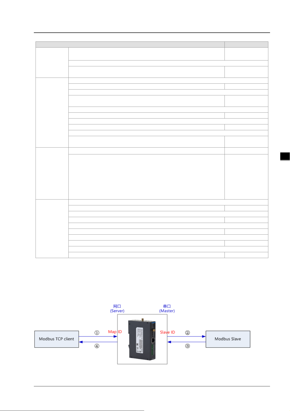
3.3.2 Serial server
The function allows DVW series to connect with the assigned server, while also pack serial port data into
TCP/UDP and send it to the server for TCP or UDP client.
3-12
Page 32
Chapter 3 Function Guide
_
3.3.2.1 RS-485
In this mode, the DVW series is used as client’s serial server of communication via TCP/UDP protocol which
can transmit RS-485 data to the serial server.
3
3-13
Page 33

_
3
Delta Industrial Wireless DVW-W0 1I2-E1 Series User Manual
Description Default value
Operation mode
Select the current operating serial port default to “Close”, other options include:
1. TCP mode: serve as client’s serial server of communication via TCP protocol.
2. UDP mode: serve as client’s serial server of communication via UDP protocol.
Baud rate
Set baud rates for serial ports. Optional values include 2400, 4800,
9600, 19200, 38400, 57600, 115200.
Serial
communication
parameters
TCP mode
3-14
Data bit
Set data bits for serial ports. Optional values include 7 or 8. 8
Parity bit
Set parity bits for serial ports. Optional values include “none”, “odd”
or “even”.
Stop bit
Set stop bits for serial ports. Optional values include 1 or 2. 1
TCP keepalive time
Configure idle time of TCP to auto-close TCP connection. Optional
values from 0 to 99 minutes.
0: TCP connection will not be closed due to idle (always open)
Close
9600
None
7
Page 34

Chapter 3 Function Guide
_
Description Default value
1~99: When idle time reaches setting value, TCP connection is
closed.
Destination IP and port
Set connected serial server IP range and port, the IPand port
cannot have the same configuration. Max. 4 serial servers for
simultaneous connection.
Max. payload length
Set the waiting length of cumulative data for data packet
transmission, the range is 0 to 1024 byte; set 0 for immediate data
transmission.
Minimal packet interval
Set the waiting time to forcing data packet transmission, the range
is 0 to 65535 ms; set 0 to permanently avoid forcing of
transmission; For data transmission, set range is between 1 to
65535 when the time reaches setting value or cumulative data
length reaches the setting length.
Destination IP and port
Set the connected serial server IP and ports. Maximum of 4 serial
servers for simultaneous connection in UDP. Each server IP range
supports up to 99 IP address, meaning the max. number of IP
between starting and ending IP is 99. The IP and ports cannot hav e
the same configuration.
Source port
Set monitoring source port. 15000
UDP mode
3.3.2.2 RS-232
In this mode, the DVW series is used as client’s serial server of communication via TCP/UDP protocol which
can transmit RS-232 data to the serial server.
Max. payload length
Set the waiting length of cumulative data for data packet
transmission, the range is 0 to 1024 byte; set 0 for immediate data
transmission.
Minimal packet interval
Set the waiting time to forcing data packet transmission, the range
is 0 to 65535 ms; set 0 to permanently avoid forcing of
transmission; For data transmission, set range is between 1 to
65535 when the time reaches setting value or cumulative data
length reaches the setting length.
None
0
0
None
0
0
3
3-15
Page 35

_
3
Delta Industrial Wireless DVW-W0 1I2-E1 Series User Manual
3-16
Page 36

Chapter 3 Function Guide
_
3
Description Default value
Operation mode
Select the present operating serial port default to “Close”, other options include:
1. TCP mode: serve as client’s serial server of communication via TCP protocol.
2. UDP mode: serve as client’s serial server of communication via UDP proto col.
Baud rate
Set baud rates for serial ports. Selected values include 240 0, 4800,
9600, 19200, 38400, 57600, 115200.
Serial
communication
parameters
Data bit
Set data bits for serial ports. Optional values include 7 or 8. 8
Parity bit
Set parity bits for serial ports. Optional values include “none”, “odd”
or “even”.
Stop bit
Set stop bits for serial ports. Optional values include 1 or 2. 1
Close
9600
None
3-17
Page 37

_
3
Delta Industrial Wireless DVW-W0 1I2-E1 Series User Manual
Description Default value
TCP mode
UDP mode
Flow Control
Set types of flow control. Optional values include “XON/XOFF”,
“RTS/CTS”.
TCP keepalive time
Configure idle time of TCP to auto-close TCP connection. Optional
values from 0 to 99 minutes.
0: TCP connection will not be closed due to idle (always open)
1~99: When idle time reaches setting value, TCP connection is
closed.
Destination IP and port
Set connected serial server IP range and port, the IPand port
cannot have the same configuration. Max. 4 serial servers for
simultaneous connection.
Max. payload length
Set the waiting length of cumulative data for data packet
transmission, the range is 0 to 1024 byte; set 0 for immediate data
transmission.
Minimal packet interval
Set the waiting time to forcing data packet transmission, the range
is 0 to 65535 ms; set 0 to permanently avoid forcing of
transmission; For data transmission, set range is between 1 to
65535 when the time reaches setting value or cumulative data
length reaches the setting length.
Destination IP and port
Set the connected serial server IP and ports. Maximum of 4 serial
servers for simultaneous connection in UDP. Each server IP range
supports up to 99 IP address, meaning the max. number of IP
between starting and ending IP is 99. The IP and ports cannot hav e
the same configuration.
Source port
Set monitoring source port. 16000
Max. payload length
Set the waiting length of cumulative data for data packet
transmission, the range is 0 to 1024 byte; set 0 for immediate data
transmission.
Minimal packet interval
Set the waiting time to forcing data packet transmission, the range
is 0 to 65535 ms; set 0 to permanently avoid forcing of
transmission; For data transmission, set range is between 1 to
65535 when the time reaches setting value or cumulative data
length reaches the setting length.
None
7
None
0
0
None
0
0
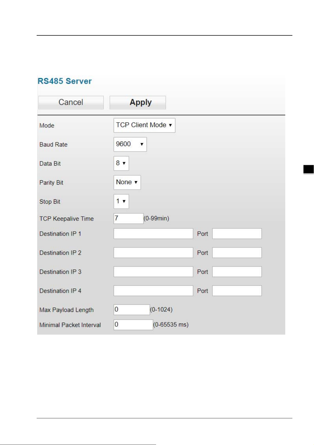
3.3.3 Transparent server
In this mode, the DVW device serves as TCP servers that receives data packet from assigned ports and
transmits to RS-485 or RS-232 serial ports without any processing.
3.3.3.1 RS-485 transparent server
3-18
Page 38

Chapter 3 Function Guide
_
3
Description Default value
Operation mode
Select present operating serial port mode from the following options:
1. TCP server: as TCP server, create connection once receive client host request
then client host and DVW device can start data transmission.
2. Close: close transparent server function.
TCP port
Set the port for TCP Server monitoring data packet. 12580
Baud rate
Set baud rates for serial ports. Optional values include 2400, 4800, 9600, 19200,
38400, 57600, 115200.
Data bit
Set data bits for serial ports. Optional values include 7 or 8. 8
Parity bit
Set parity bits for serial ports. Optional values include “nonel”, “odd”or “even”. None
Stop bit
Set stop bits for serial ports. Optional values include 1or 2. 1
3.3.3.2 RS-232 transparent server
Close
9600
3-19
Page 39
_
3
Delta Industrial Wireless DVW-W0 1I2-E1 Series User Manual
Description Default value
Operation mode
Select present operating serial port mode from the following options:
1. TCP server: as TCP server, create connection once receive client host request
then client host and DVW device can start data transmission.
2. Close: close transparent server function.
TCP port
Set the port for TCP Server monitoring data packet. 12581
Baud rate
Set baud rates for serial ports. Optional values include 2400, 4800, 9600, 19200,
38400, 57600, 115200.
Data bit
Set data bits for serial ports. Optional values include 7 or 8. 8
Parity bit
Set parity bits for serial ports. Optional values include “None”, “odd”or “even”. None
Stop bit
Set stop bits for serial ports. Optional values include 1or 2. 1
Flow control
Set types of flow control. Optional values include “XON/XOFF”, “RTS/CTS”. Non e
Close
9600
3-20
Page 40

Chapter 3 Function Guide
_
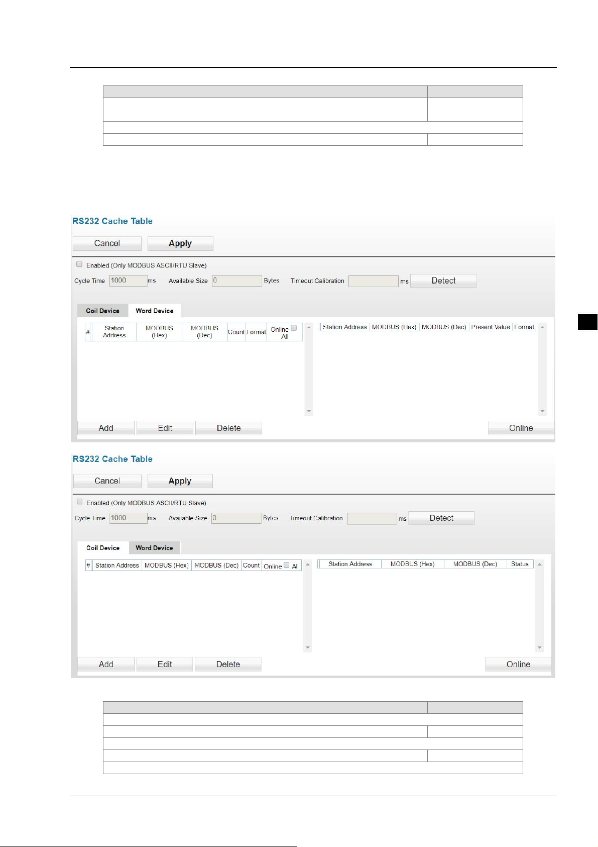
3.3.4 MODBUS cache table
Since the transmission speed of Ethernet interface is faster than that of serial ports, therefore, when Ethernet
devices send requests to serial devices, more time is required for waiting serial port data. MODBUS cache
table provides PLCs with relevant configuration information (e.g. station ID, MODBUS IP). The DVW device
can send request to receive serial port device data based on prior MODBUS cache table. When Ethernet
devices requests for transmission to DVW device, DVW can immediately respond to data. Because DV W ha s
already receive the data in advance, so it does not need to transfer the requests to serial devices and the
function can also be used in MODBUS ASCII/RTU slave mode.
3.3.4.1 RS-485 cache table
On the left part of the cache table page displays information regarding configuration; click Online and data
read based on configuration messages are shown on the right.
3
Explanation Default value
Enabled
Set MODBUS cache function to enable or not enable. Not checked
Cycle time
Set the time for sending requests to serial devices. 1000
Available size
Displays the available data size for monitoing.
Timeout calibration
Calibrate the response timeout. When users click Detect, the DVW
device will use the MODBUS cache table for communication.
3-21
Page 41

_
3
Delta Industrial Wireless DVW-W0 1I2-E1 Series User Manual
Explanation Default value
Add
Add a configuration message (up to 100 messages).
Edit
Edit selected configuration messages.
Delete
Delete assigned configuration messages.
Online
When clicked, real-time values gathered for relevant addresses are
shown on the right section of the page.
Word device
Item Explanation
Station address The device station ID.
MODBUS (Hex) MODBUS in hexadecimal values
MODBUS (Dec) MODBUS in decimal values
Present value MODB US present value.
Format Hexadecimal or decimal format.
Coil device
Item Explanation
Station address The device station ID.
MODBUS (Hex) MODBUS in hexadecimal values
MODBUS (Dec) MODBUS in decimal values
Status Values of MODBUS.
To add/ edit a configuration (see below):
3-22
Explanation Default value
Station address
The device station ID. None
MODBUS (Hex)
MODBUS in hexadecimal values. None
MODBUS (Dec)
MODBUS in decimal values None
Count
Starting from MODBUS address and connecting to monitored data
size.
Format
None
Page 42
Chapter 3 Function Guide
_
Explanation Default value
Set format to Hex, Dec, Bin (hexadecimal, decimal, binary).
When add or edit coil device types, format is not required.
Online
Set or not to set data display on MODBUS monitoring table. Not checked
3.3.4.2 RS-232 cache table
On the left part of the cache table page displays information regarding configuration; click Online and data
read based on configuration messages are shown on the right.
Hex
3
Explanation Default value
Enabled
Set MODBUS cache function to enable or not enable. Not checked
Cycle time
Set the time for sending requests to serial devices. 1000
Available size
3-23
Page 43

_
3
Delta Industrial Wireless DVW-W0 1I2-E1 Series User Manual
Explanation Default value
Displays the available data size for monitoing.
Timeout calibration
Calibrate the response timeout. When users click Detect, the DVW
device will use the MODBUS cache table for communication.
Add
Add a configuration message (up to 100 messages). None
Edit
Edit selected configuration messages. None
Delete
Delete assigned configuration messages. None
Online
When clicked, real-time values gathered for relevant addresses are
shown on the right section of the page.
Word device
Item Explanation
Station address The device station ID.
MODBUS (Hex) MODBUS in hexadecimal values
MODBUS (Dec) MODBUS in decimal values
Present value MODB US present value.
Format Hexadecimal or decimal format.
Coil device
Item Explanation
Station address The device station ID.
MODBUS (Hex) MODBUS in hexadecimal values
MODBUS (Dec) MODBUS in decimal values
Status Values of MODBUS.
To add/ edit a configuration (see below):
None
Explanation Default value
Station address
The device station ID. None
MODBUS (Hex)
MODBUS in hexadecimal values. None
MODBUS (Dec)
MODBUS in decimal values None
Count
3-24
Page 44

Chapter 3 Function Guide
_
Explanation Default value
Starting from MODBUS address and connecting to monitored data
size.
Format
Set format to Hex, Dec, Bin (hexadecimal, decimal, binary).
When add or edit coil device types, format is not required.
Online
Set or not to set data display on MODBUS monitoring table. Not checked
None
Hex
3.4 WLAN management - 2.4G
The WLAN management focuses on configuring 2.4G WIFI operatio n mode and its correspo nding parameters.
Please refer to the manual for accurate configuration before setup.
3.4.1 Operation mode
DVW-W01I2-E1 provides 2 different WIFI operation modes including AP and client mode that allow users to
easily configure wireless network environment. Please first set DVW-W01I2-E1 operation mode, then
configure WLAN.
3
Description Default value
RF
To enable or disable wireless function. Enabled
Operation mode
Set wireless operation mode:
AP mode: used as an intermediate point for wired and wireless
devices connection, data transmission and more.
Client mode: DVW-W02W2-E2 operating in client mode can
perform wireless data transmission via AP.
Region
Show the country or region for the device (display only, can’t revise by
user)
Attention
2.4G and 5G WIFI cannot operate in client mode simultaneously.
AP
U.S
3.4.2 WLAN 2.4G
The setting page focuses on the basic and adanced configuration of 2.4G network in AP or client mode.
3-25
Page 45
_
3
Delta Industrial Wireless DVW-W0 1I2-E1 Series User Manual
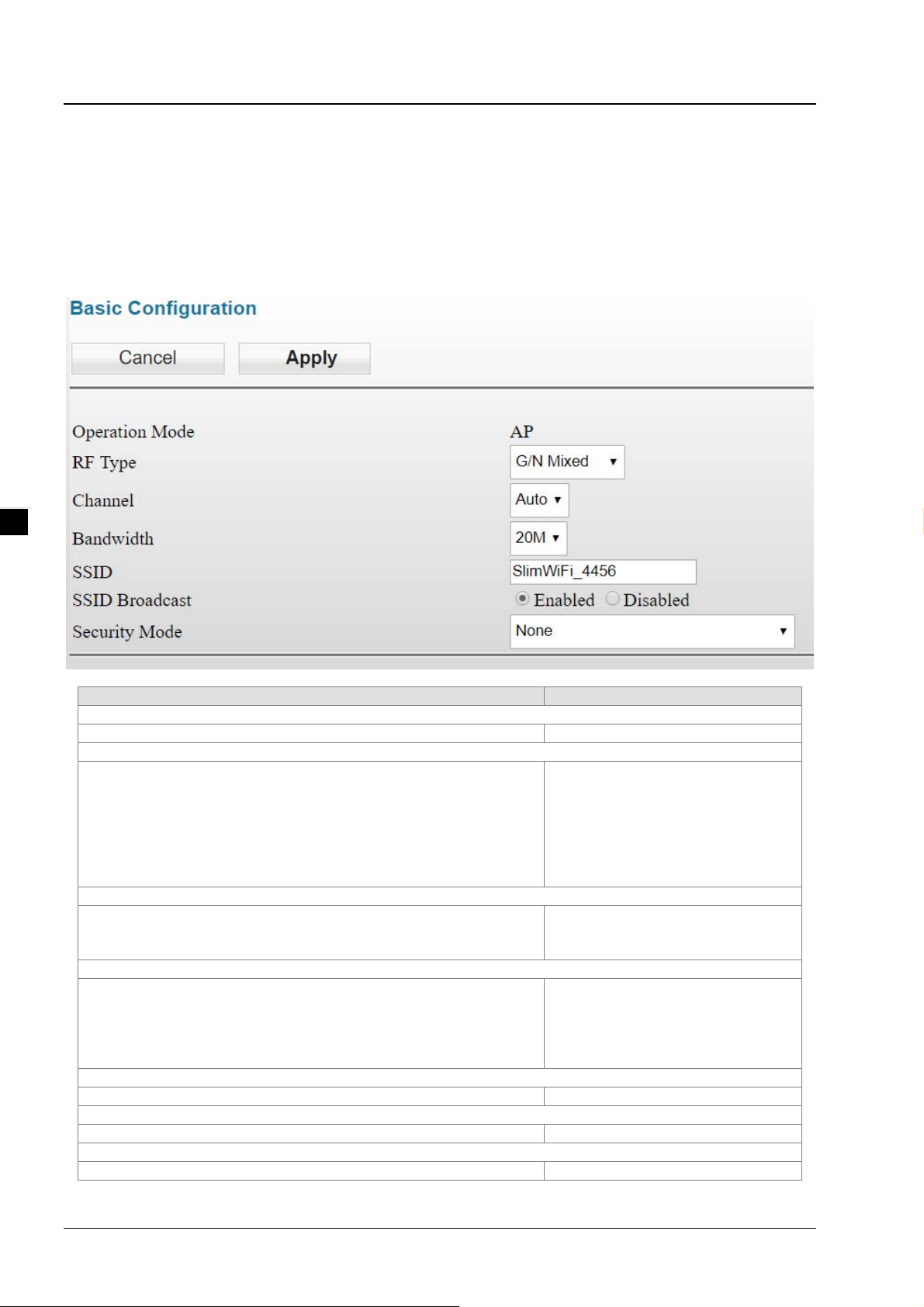
3.4.2.1 Basic configuration
The setting corresponds to operation mode. Different operation mode will have different basic configurations.
AP mode:
In AP mode, users can add or edit WLAN basic configurations. For example, RF type, channel, SSID, SSID
broadcast and security mode. Click Apply once configurations are completed.
Description Deault value
Operation mode
Display present operation mode
RF type
Select from the following types:
G: only supports IEEE 802.11g standard
B/G Mixed: supports mixed mode IEEE 802.11b/g
G/N Mixed: supports mixed mode IEEE 802.11g/n, but
does not support 802.11b
B/G/N Mixed: supports mixed mode IEEE 802.11b/g/n
N Only: only supports 2.4GHz IEEE 802.11n standard
Channel
Set AP operating channels from the following options:
Auto
1-11
Bandwidth
Set WIFI 2.4G with the following bandwidth options:
20MHz
40MHz
20MHz penetrability is better and contains long transmission
distanace but is slower in speed.
SSID
Type the wireless device name that consists of 1-32 characters “SlimWiFi_”+”MAC last 4 digits”
SSID broadcast
Set enable or disable SSID broadcast Enabled
Maximum number of client connections
Set the maximum number of clients allowed to connect to this AP. 20
G/N Mixed
Auto
20MHz
3-26
Page 46

Chapter 3 Function Guide
_
Description Deault value
WMM
After selecting this option, multimedia data is given priority during
data transmission.
Client isolation
After selecting this option, clients connected to this AP cannot
access each other.
Security mode
Set AP operation security mode from the following options:
None
WPA2-PSK[AES]
WPA-PSK[TKIP]+ WPA2-PSK[AES]
For more security mode information, refer to section 3.4.2.2.
Client mode
In client mode, click Site Survey and the existed network SSID will appear, then choose the matching SSID.
For example, the matching SSID is configured to WEP or WPA/WPA2-PSK. Please enter the correct
password then click Apply to connect with AP.
Check
Uncheck
None
3
3-27
Page 47
_
3
Delta Industrial Wireless DVW-W0 1I2-E1 Series User Manual
Description Default value
EXTAP
Enabled: When EXTAP is enabled, client compatibility increases
along with more compatible AP.
Disabled: When EXTAP is disabled, recommend using the AP of
DVW-W01I2-E1 for enhanced connection.
Client mode
Disabled: Operation under normal WiFi client mode.
Roaming: client support fast roaming protocol of personal level.
Attention
In client mode, RF type and channel in gray background cannot be configured;
while in AP mode, simultaneous configuration for RF type, channel and security
mode begins once matching is successful.
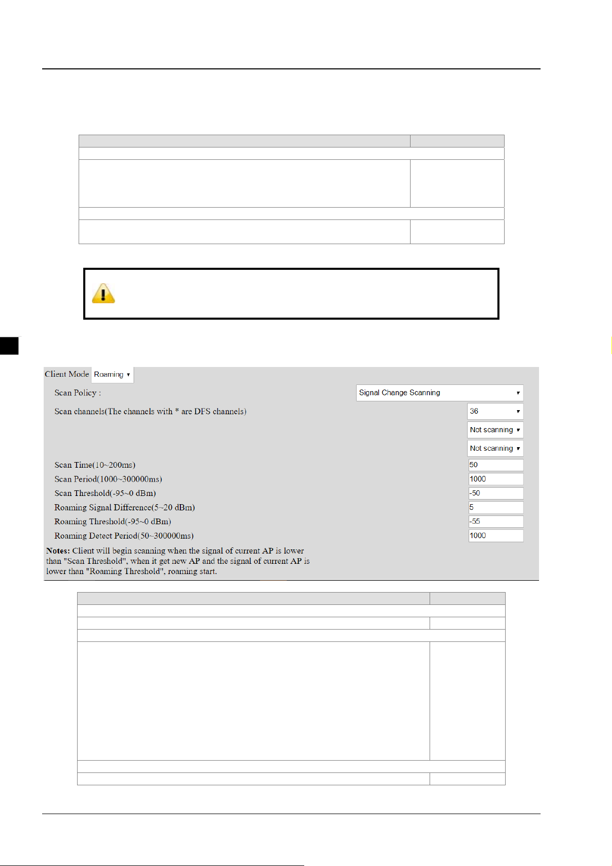
Start roaming mode, the DVW devices support fast roaming protocol of personal level and can fulfill the need
for fast switching APs in maintaining the operation under wireless application environment.
Disabled
Disabled
3-28
Description Default value
Client Mode
To enable or not enable fast roaming function. Disabled
Scan channel
To set fast roaming, DVW scans the assigned AP channels; when there are
more channels that need to be determined, roaming speed is also more
easily affected.
Below are options in the first drop-down list:
-- Auto: Scan all the channels and select an option without selecting the
second and third drop-down lists.
--The present AP channels in connection with DVW.
Below are options in the second and third drop-down list:
-- Not scanning: Scanning channels only from the previous drop-down list.
-- Channel value: Select desired channels for scanning.
Scan time
When DVW scans for available APs, set the scan time for each 50
Present AP
channel
Page 48

Chapter 3 Function Guide
_
Description Default value
channel.Setting range: 10~200ms.
Scan period
Set the AP interval period for DVW scan. Setting range: 1000~300000ms。
Scan threshold
Set the AP threshold once DVW is triggered for scanning, but only when the
AP’s transmission power connected to the present DVW is lower than the
threshold value, the DVW will scan the available AP based on the scan
period. Setting range: -95~0 dBm.
Roaming signal difference
Set DVW roaming signal difference which is a condition to execute DVW
switching action. When the signal difference between present AP’s
transmission power in connection with DVW and the new AP is larger than
the setting value, the DVW will switch to the new AP. Setting range: 5~20
dBm.
Roaming threshold
Set DVW roaming threshold which is a condition for DVW to execute switch
action.when the present AP’s transmission power in connection with DVW
is lower than the setting value, the DVW can switch to new AP.
Setting range: -95~0 dBm.
Roaming detect period
Set DVW to detect whether the interval period of the two roaming
conditions are satisfied; When both conditions are satisfied, the DVW can
execute switching. Setting range: 50~300000ms.
3.4.2.2 Security mode
The device provides 5 standard security modes including none, WEP, WPA-PSK[TKIP], WPA2-PSK[AES]
and WPA-PSK[TKIP] + WPA2-PSK[AES]. Users can set the security mode base on your own needs.
Security mode: None
1000
-50
5
-55
50
3
No security mode. When selecting this option, any client can connect to DVW-W02W2-E2 device without
security mode.
Security mode: WPA/WPA2 Personal
The WIFI alliance developed Wi-Fi Protected Access (WPA) and Wi-Fi Protected Access 2 (WPA2) to protect
two securtiy protocols and security identifications in wireless network. The WPA/WPA2-Personal or so-called
WPA / WPA-PSK (Pre-Shared Key) has two encryption methods including TKIP (Temporal Key Integrity
Protocol) and AES (Advance Encryption System). TKIP can automatically create a new network password
every few minutes which can prevent attackers from continuously collecting sufficient data in accessing your
network. AES represents Advance Encryption System that encrypts 128-bit, 192-bit or 256-bit block and is
considered the safest option for WIFI encryption.
Description Default value
Security options
WPA2-PSK[AES]: Enable AES encryption method.
WPA-PSK[TKIP]+ WPA2-PSK[AES]: Supports WPA-PSK
and WPA2-PSK. Broadcast packets uses TKIP. For
point-to-point transmission, WPA-PSK client uses TKIP and
WPA2-PSK client uses AES.
Password
None
3-29
Page 49

Delta Industrial Wireless DVW-W0 1I2-E1 Series User Manual
_
Description Default value
Password phrase requires 8 to 63 ASCII characters or 64
hexadecimal digit.
3.4.2.3 Advanced configuration
The configuration provides users to execute advanced parameter settings based on different on-site wireless
environment.
None
3
Description Default value
Transmission power
Set the transmission power. The transmission power gets strong er
as setting value becomes higher and the influence range widens.
Range option 1 to 20.
Beacon interval
The beacon interval of a wireless broadcast, the unit is ms. When
roaming is required, users can adjust to lower value for faster
connection; adjust to higher value for power saving. Input range:
40-1000.
20
150
3.5 WLAN management - 5G
The WLAN management focuses on configuring 5G WIFI operation mode and its correspondin g parameters.
Please refer to the manual for accurate configuration before setup.
3.5.1 Operation mode
DVW-W01I2-E1 provides 2 different WIFI operation modes including AP and client mode that allow users to
easily configure wireless network environment. Please first set DVW-W01I2-E1 operation mode, then
configure WLAN.
3-30
Page 50

Chapter 3 Function Guide
_
Description Default value
RF
To enable or disable wireless function. Enabled
Operation mode
Set wireless operation mode:
AP mode: used as an intermediate point for wired and wireless
devices connection, data transmission and more.
Client mode: DVW-W02W2-E2 operating in client mode can perform
wireless data transmission via AP.
Region
Show the country or region for the device (display only, can’t revise by user) U.S
Attention
2.4G and 5G WIFI cannot operate in client mode simultaneously.
3.5.2 WLAN 5G
AP
3
The setting page focuses on the basic and adanced configuration of 5G network in AP or client mode.
3.5.2.1 Basic configuration
The setting corresponds to operation mode. Different operation mode will have different basic configurations.
AP mode:
In AP mode, users can add or edit WLAN basic configurations. For example, RF type, channel, SSID, SSID
broadcast and security mode. Click Apply once configurations are completed.
3-31
Page 51

_
3
Delta Industrial Wireless DVW-W0 1I2-E1 Series User Manual
Description Default value
Operation mode
Display present operation mode
RF type
Select from the following types:
AC/N Mixed: only supports mixed mode IEEE 802.11ac/n
A/N Mixed: supports mixed mode IEEE 802.11a/n
N Only: only supports 5GHz IEEE 802.11n standard
A: only supports 5GHz IEEE 802.11n standard
Channel
Set AP operating channels from the following options:
36/40/44/48/52/60/64/100/104/108/112/116/120/124/128/132/136/140
Bandwidth
Set WIFI 5G with the following bandwidth options:
20MHz
40MHz
80MHz
20MHz penetrability is better and contains long transmission distanace but is
slower in speed.
SSID
Type the wireless device name that consists of 1-32 characters
SSID broadcast
Set enable or disable SSID broadcast Enabled
Security mode
Set AP operation security mode from the following options:
None
WPA2-PSK[AES]
WPA-PSK[TKIP]+ WPA2-PSK[AES]
For more security mode information, refer to section 3.4.2.2
Client mode
AC/N Mixed
36
80MHz
“SlimWiFi_”+”MAC
last 4 digits”+”5G”
None
In client mode, click Site Survey and the existed network SSID will appear, then choose the matching SSID.
For example, the matching SSID is configured to WEP or WPA/WPA2-PSK. Please enter the correct
password then click Apply to connect with AP.
3-32
Page 52

Chapter 3 Function Guide
_
3
Description Default value
EXTAP
Enabled: When EXTAP is enabled, client compatibility increases
along with more compatible AP.
Disabled: When EXTAP is disabled, recommend using the AP of
DVW-W01I2-E1 for enhanced connection.
Client mode
Disabled: Operation under normal WiFi client mode.
Roaming: client support fast roaming protocol of personal level
Attention
In client mode, RF type and channel in gray background cannot be configured;
while in AP mode, simultaneous configuration for RF type, channel and security
mode begins once matching is successful.
Start roaming mode, the DVW devices support fast roaming protocol of personal level and can fulfill the need
for fast switching APs in maintaining the operation under wireless application environment.
Disabled
Disabled
3-33
Page 53

Delta Industrial Wireless DVW-W0 1I2-E1 Series User Manual
_
3
Description Default value
Client Mode
To enable or not enable fast roaming function. Disabled
Scan channel
Set DVW scan strategy, the system offers two options.
Scan changing signals:
When the signal of AP in connection with DVW is lower than scan threshold,
once signal value changes and triggers DVW to scan for available AP; the
AP signal information received provides DVW to determine in switching or
not; the parameter of scan period is invalid under this mode.
Periodic scanning or scan changing signals:
When the signal of AP in connection with DVW is lower than scan threshold,
the DVW is triggered according to scan period or changing signal values for
available AP; the AP signal information received provides DVW to determine
in switching or not
To set fast roaming, DVW scans the assigned AP channels; when there are
more channels that need to be determined, roaming speed is also more
easily affected.
Below are options in the first drop-down list:
-- Auto: Scan all the channels and select an option without selecting the
second and third drop-down lists.
--The present AP channels in connection with DVW.
Below are options in the second and third drop-down list:
-- Not scanning: Scanning channels only from the previous drop-down list.
-- Channel value: Select desired channels for scanning.
Scan time
When DVW scans for available APs, set the scan time for each
channel.Setting range: 10~200ms.
Scan period
Set the AP interval period for DVW scan. Setting range: 1000~300000ms。
Scan threshold
Set the AP threshold once DVW is triggered for scanning, but only when the
AP’s transmission power connected to the present DVW is lower than the
threshold value, the DVW will scan the available AP based on the scan
period. Setting range: -95~0 dBm.
Roaming signal difference
Set DVW roaming signal difference which is a condition for DVW to execute
switch action. When the signal difference between present AP’s transmissi on
power in connection with DVW and the new AP is larger than the setting
value, the DVW will switch to the new AP. Setting range: 5~20 dBm.
Scan changing
signals
Auto
50
1000
-50
5
3-34
Page 54

Chapter 3 Function Guide
_
Description Default value
Roaming threshold
Set DVW roaming threshold which is a condition for DVW to execute switch
action. When the present AP’s transmission power in connection with DVW
is lower than the setting value, the DVW can switch to new AP.
Setting range: -95~0 dBm.
Roaming detect period
Set DVW to detect whether the interval period of the two roaming conditions
are satisfied; when both conditions are satisfied, the DVW can execute
switching. Setting range: 50~300000ms.
3.5.2.2 Advanced configuration
The configuration provides users to execute advanced parameter settings based on different on-site wireless
environment.
-55
50
3
Description Default value
Transmission power
Set the transmission power. The transmission power gets stronger as
setting value becomes higher and the influence range widens.
Range option 1 to 20.
Beacon interval
The beacon interval of a wireless broadcast, the unit is ms. When
roaming is required, users can adjust to lower value for faster
connection; adjust to higher value for power saving. Input range:
40-1000.
20
150
3.6 Auto alarm function
3.6.1 Using relay for alarm system
The relay switch used for alarm system mainly monitors specified interface or target status; currently, the
system defined two types of trigger events: DI and port link. When trigger is enabled, the interface or target
behavior fulfills predefined behavior and relays used for alarm (DO closed) is triggered, indicator lights
perform corresponding actions at the same time.
3-35
Page 55
Delta Industrial Wireless DVW-W0 1I2-E1 Series User Manual
_
3
3.7 Maintenance
3.7.1 Session timeout
Users can set session timeout but when the setting time is exceeded, it will auto log off the system and a
message regarding the action is presented to users. We recommend configuring this function for enhanced
system security.
Description Default value
Session timeout
Set the time for session timeout.
Timeout setting range is 0 to 60 min.
Set to 0 and session timeout will never occur.
3.7.2 Password
30
Users can change the password of DVW-W01I2-E1 log in page. To successfully configure a new set of
password, users need to type in the old password.
3-36
Page 56

Chapter 3 Function Guide
_
Description Default value
Old password
The current admin. password
New password
Set new admin. password
Repeat new password
Repeat the new password
3.7.3 System log backup
The function allows documents derived from the logs to be stored in PCs or storage devices.
3.7.4 Roaming log
Roaming log function can record the device as WIFI station that quickly swich from one AP message to
another including SSID in AP’s source and transmission power as well as SSID in destination AP and
transmission power.
3
Description Default value
BSSID
MAC in AP’s source destination AP N/A
Power
RF power of AP N/A
Threshold
Switch threshold setting by users N/A
Connect
Previous AP connection time N/A
Handoff
The handoff time for switching to AP roaming N/A
ID
The number of times for roaming N/A
3-37
Page 57

Delta Industrial Wireless DVW-W0 1I2-E1 Series User Manual
_
3.7.5 Serial log
From selecting a serial, users can determine the assigned log level and serial logs.
3
The image above shows the system can derive all log level as “Error” from RS232 serial logger. Users can
click Backup button and download the logs in PCs.
3.7.6 Ping
Ping function can help admin to analyze network status. Type in the IP address to search for connection
status.
3.7.7 Ping detection
When users enable Ping detection for AP connection, the AP’s IP address is usually configured so that when
the number of Ping failure reaches the setting number, the system is bound to start WIFI reset.
3-38
Page 58

Chapter 3 Function Guide
_
3.7.8 Firmware upgrade
DVW-W01I2-E1 releases new upgraded firmware regularly to enhance product performance an d include
more functions. We strongly recommend users to do regular checkup and proceed firmware upgrade for your
DVW-W01I2-E1 device. Please download the latest firmware document for our website.
3.7.9 Configuration Import & Export
The “Backup” button allows the documents derived from current configuration messages to st ore in your PCs
or storage devices.
The “Restore” button can import the assigned document by users into the device.
3.7.10 Load factory default
3
When “Load” is clicked, the DVW-W01I2-E1 device restores the default values. In addition, the panel
hardware contains RST button for devices to restore default settings.
3-39
Page 59

_
3
Delta Industrial Wireless DVW-W0 1I2-E1 Series User Manual
3.7.11 Log off
Users can click Log off to exist the configuration page. When configuration and operating on the
DVW-W01I2-E1 device is complete, we recommend to log off from your current account for security
consideration. When Log off is clicked, the log-in page appears.
3-40
 Loading...