

Page 1

DVPCOPM-SL
CANopen Communication Module
Application Manual
Page 2

Page 3

CANopen Communication Module DVPCOPM-SL
Warning
Please read this instruction carefully before use and follow this instruction to operate the device in order to prevent
damages on the device or injuries to staff.
Switch off the power before wiring.
DVPCOPM-SL is an OPEN TYPE device and therefore should be installed in an enclosure free of airborne dust,
humidity, electric shock and vibration. The enclosure should prevent non-maintenance staff from operating the
device (e.g. key or specific tools are required for operating the enclosure) in case danger and damage on the
device may occur.
DVPCOPM-SL is to be used for controlling the operating machine and equipment. In order not to damage it, only
qualified professional staff familiar with the structure and operation of DVPCOPM-SL can install, operate, wire
and maintain it.
DO NOT connect input AC power supply to any of the I/O terminals; otherwise serious damage may occur. Check
all the wirings again before switching on the power and DO NOT touch any terminal when the power is switched
on. Make sure the ground terminal
1 INTRODUCTION...................................................................................................................................3
2 PRODUCT PROFILE & OUTLINE .......................................................................................................5
Table of Contents
1.1 Features....................................................................................................................................3
1.2 Functions...................................................................................................................................4
2.1 Dimension .................................................................................................................................5
2.2 Product Profiles.........................................................................................................................5
2.3 CANopen Connection Port........................................................................................................6
2.4 Address Switch..........................................................................................................................6
2.5 Function Switch.........................................................................................................................6
2.6 Digital Indicator..........................................................................................................................7
is correctly grounded in order to prevent electromagnetic interference.
3 BASIC OPERATION.............................................................................................................................7
3.1 Connecting DVPCOPM-SL to DVP-SV MPU............................................................................7
3.2 Installing DVPCOPM-SL and DVP-SV MPU on DIN Rail..........................................................7
3.3 Connecting to CANopen Connection Port.................................................................................8
4 CONSTRUCTING CANOPEN NETWORK...........................................................................................8
4.1 How to Construct a CANopen Network.....................................................................................8
4.2 Data Mapping in CANopen Network .......................................................................................10
4.3 How to Configure Network by Delta CANopenBuilder Software.............................................11
4.4 Saving the Configuration Data ................................................................................................19
4.5 CANopen Network Control......................................................................................................19
DVP-PLC Application Manual
1
Page 4

CANopen Communication Module DVPCOPM-SL
5 SENDING SDO, NMT AND READING EMERGENCY BY LADDER DIAGRAM.............................. 20
5.1 The Principle........................................................................................................................... 20
5.2 Structure of SDO Request Message.......................................................................................20
5.3 Structure of NMT Service Message........................................................................................ 21
5.4 Structure of Emergency Request Message............................................................................ 22
5.5 Application Examples ............................................................................................................. 23
6 LED INDICATOR & TROUBLE-SHOOTING ..................................................................................... 27
6.1 POWER LED.......................................................................................................................... 28
6.2 RUN LED................................................................................................................................ 28
6.3 ERR LED................................................................................................................................28
6.4 Codes in Digital Display.......................................................................................................... 28
2
DVP-PLC Application Manual
Page 5

1 Introduction
1. To ensure correct installation and operati on of DVPCOPM-SL, please read this chapter carefully before
using your DVPCOPM-SL.
2. This chapter only provides introductory information on DVPCOPM-SL. For more detaile d information on
CANopen protocol, please refer to relevant references or literatures.
3. DVPCOPM-SL is a CANopen module op erating on the left side of DVP-SV series PLC MPU. When DVP-SV
is connected to CANopen network through DVPCOPM-SL, DVPCOPM-SL will serve as the data exchange
interface between DVP-SV and other slaves on the bus. DVPCOPM-SL is in charge of sending the data in
DVP-SV to the slaves on the bus, and at the same time collecting the data returned from each slave and
sending them back to DVP-SV.
1.1 Features
DVPCOPM-SL can be used as the master in CANopen network, as well as the slave for other masters.
As a master, DVPCOPM-S L features:
z Complying with CANopen standard protocol DS301v4.02.
CANopen Communication Module DVPCOPM-SL
z Supporting NMT Master Service.
z Error control: Supporting Heartbeat/Node Guarding Protocol.
z Supporting PDO Service.
Max. 200 RxPDOs and 390 bytes of data
Max. 200 TxPDOs and 390 bytes of data
Each slave can be allocated maximum 8 TxPDOs and 8 RxPDOs.
z PDO transmission type: Supporting event trigger, time trigger, synchronous cycle, and synchronous
non-cycle.
z PDO mapping: Every PDO is able to map maximum 32 parameters.
Type of mapping data supported:
Storage sp ace Data type
1 bit BOOL
8 bits SINT USINT BYTE
16 bits INT UINT WORD
32 bits DINT UDINT REAL DWORD
64 bits LINT ULINT LREAL LWORD
z Supporting SDO Service.
Number of server: 0
Number of user: 3
z Supporting standard expedited SDO transmission mode.
z Supporting Auto SDO func tion. Able to execute maximum 20 Auto SDOs to each slave.
z Supporting reading/writing of data in slave by using SDO Service in the ladder diagram in PLC.
z Supporting Emergency Protocol:
Able to store 5 latest Emergency messages for each slave.
Able to indicate Emergency messages in slave from digital display.
Able to read Emergency message through the ladder diagram in PLC.
z SYNC producer; Range: 0 ~ 65,535ms.
DVP-PLC Application Manual
3
Page 6
CANopen Communication Module DVPCOPM-SL
z As the interface between Delta CANopenBuilder software and CANopen network. The software can
configure the network directly through DVPCOPM-SL.
z In the auto data exchange with DVP-SV, the user only has to program the D register mapped in DVP-SV
without applygin FROM/TO instructions. When connected to DVP-SV/DVP-EH2-L MPU,
D6000 will be adopted temporarily.
As a slave, DVPCOPM-SL features:
z Complying with CANopen standard protocol DS301v4.02
z Supporting NMT Slave Service
z Error control: Supporting Heartbeat Protocol
z Supporting PDO Service: Each slave can be allocated maximum 8 TxPDOs and 8 RxPDO s.
z PDO transmission type: Supporting event trigger, time trigger, synchronous cycle, synchronous
non-cycle.
z Supporting SDO Service.
Number of server: 1
Number of user: 0
z Supporting standard expedited SDO transmission mode.
z Supporting Emergency Protocol.
Able to indicate Emergency event in slave through digital display.
z In the auto data exchange with DVP-SV, the user only has to program the D register mapped in DVP-SV
without applygin FROM/TO instructions.
registers after
1.2 Functions
CANopen connection
Transmission method CAN
Electrical isolation 500VDC
Interface Removable connector (5.08mm)
Transmission cable 2-wire twister shielded cable with 2-wire bus power and drain
Communication
Message type
Baud rates 10k, 20k, 50k, 125k, 250k, 500k, 800k, 1M bps (bit/sec)
Electrical specification
Power voltage 24VDC, supplied by internal bus from PLC MPU (-15% ~ 20%)
Power consumption 1.7W
Isolation voltage 500V
Environment
Noise immunity
PDO, SDO, SYNC (synchronous object), Emergency (Emergency object),
NMT
ESD (IEC 61131-2, IEC 61000-4-2): 8KV Air Discha rge, 4KV Contact
Discharge
EFT (IEC 61131-2, IEC 61000-4-4): Power Line: 2KV, Digital I/O: 1KV
Analog & Communication I/O: 1KV
Damped-Oscillatory Wav e: Power Line: 1KV, Digital I/O: 1KV
RS (IEC 61131-2, IEC 61000-4-3): 80MHz ~ 1,000MHz, 1.4GHz ~ 2.0GHz,
10V/m
4
DVP-PLC Application Manual
Page 7
CANopen Communication Module DVPCOPM-SL
Opeartion 0ºC ~ 55ºC (temperature); 50 ~ 95% (humidity); pollution degree 2
Storage -25ºC ~ 70ºC (temperature); 5 ~ 95% (humidity)
Shock/vibration
immunity
Certificates IEC 61131-2, UL508
2 Product Profile & Outline
DVPCOPM-SL is composed of CANopen connection port, address switch, function switch, an d digital
display.
2.1 Dimension
DVPCOPM-SL
POWER
RUN
ERR
90 [3.543]
International standard: IEC 61131-2, IEC 68-2-6 (TEST Fc)/IEC 61131-2 & IEC
68-2-27 (TEST Ea)
1
x16
0
x16
NODE ADDRESS
DR 2
DR 1
DR 0
IN 0
SHLD
CAN-
GND
63.4 [2.496]
3 [0.11 8]
2.2 Product Profiles
3
7
8
9
1
6
DVPCOPM-SL
POWER
RUN
ERR
NODE ADDRESS
60 [2.362]
5
x16
x16
DR 2
DR 1
DR 0
IN 0
SHLD
CAN-
GND
2
1
0
6
33.1 [1.303]
2
1. Model name 6. Fixing clip for extension module
2. Extension port 7. Address switch
DVP-PLC Application Manual
6
4
5
Page 8
CANopen Communication Module DVPCOPM-SL
3. POWER, RUN, ERR indicators 8. Function switch
4. DIN rail clip 9. CANopen connection port
5. Digital display
2.3 CANopen Connection Port
The connector is used on the connection to CANopen network. Wire by using the connector enclosed with
DVPCOPM-SL.
PIN Signal Content
1 GND 0 VDC
2 CAN_L Signal3 SHLD Shielded
4 CAN_H Signal+
5 - Reserved
2.4 Address Switch
CAN+
SHLD
CANGND
5
4
3
2
1
The switch is used on setting up the node address of DVPCOPM-SL on CANopen network. Range: 1 ~ 7F (0,
88 ~ FF are forbidden).
Switch setting Content
1 ~ 7F Valid CANopen node address
0, 80 ~ FF Invalid CANopen node address
NODE ADDRESS
x16
x16
1
0
Example: If you need to set the node address of DVPCOPM-SL to 26 (1AH), simply switch the corresponding
1
switch of x16
to 1 and the corresponding switch of x160 to A.
Note:
z Use slotted screwdriver to rotate the switch carefully in case you scratch the switch.
z Please set up the node address when the power is switched off. After the setup is completed, re-poser
DVPCOPM-SL.
2.5 Function Switch
The switch is used on setting up the baud rate between DVPCOPM-SL and CA Nopen network (DR0 ~ DR2 ).
See the table below for the baud rate and its maximum communication distance.
DR2 DR1 DR0 Baud rate (bps) Max. communication distance (m)
6
OFF OFF OFF 10k 5,000
OFF OFF ON 20k 2,500
OFF ON OFF 50k 1,000
OFF ON ON 125k 500
ON OFF OFF 250k 250
ON OFF ON 500k 100
ON ON OFF 800k 50
ON ON ON 1M 25
IN0 Reserved
DVP-PLC Application Manual
Page 9
CANopen Communication Module DVPCOPM-SL
Note:
z Use slotted screwdriver to adjust the DIP switch carefully in case you scratch the switch.
z Please set up the function switch when the power is switched off. After the setu p is completed, re-power
DVPCOPM-SL.
2.6 Digital Indicator
The digital indicator provides the following two functions:
z Displaying the node address of DVPCOPM-SL.
z Displaying the error message of slave.
3 Basic Operation
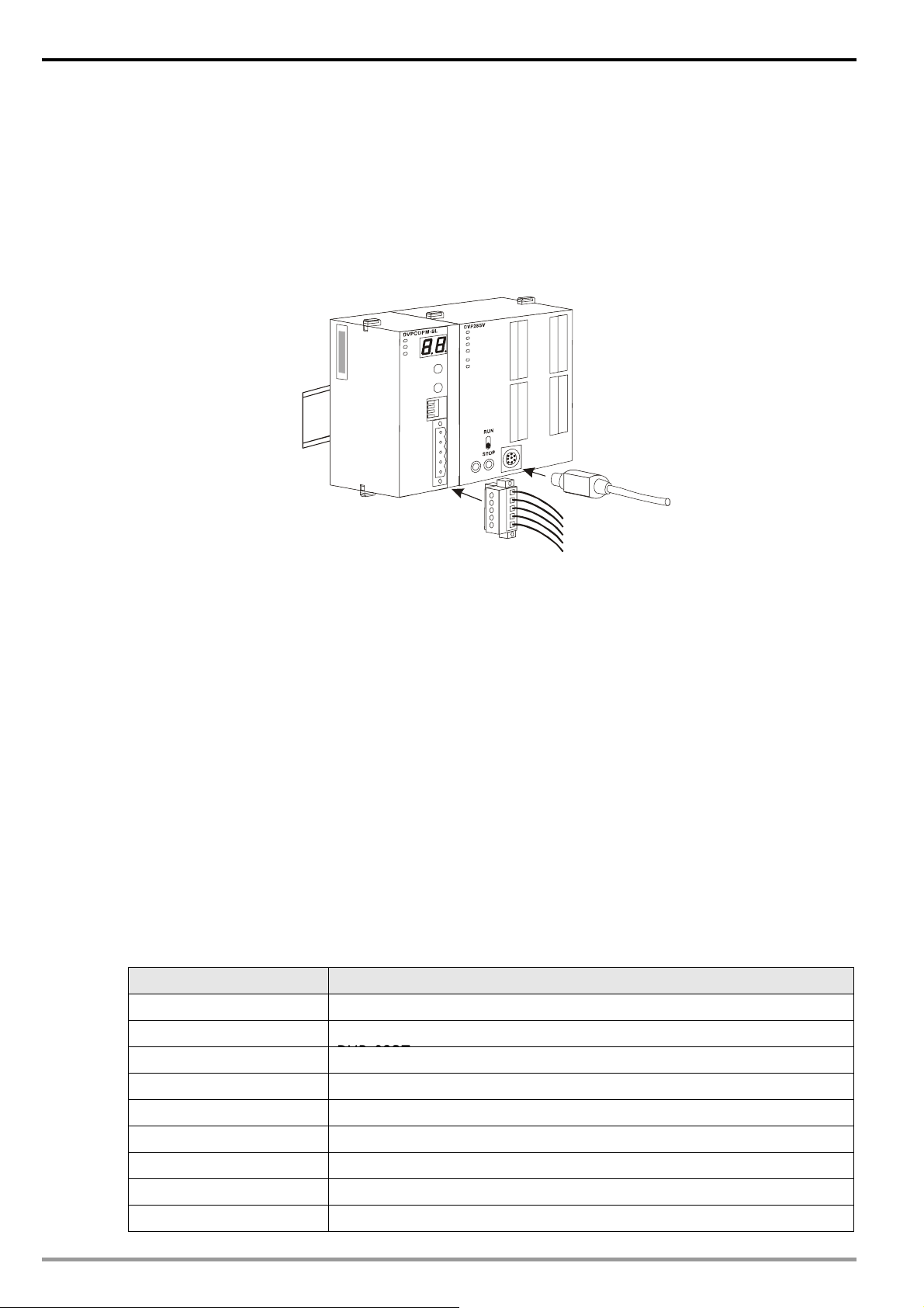
3.1 Connecting DVPCOPM-SL to DVP-SV MPU
z Open the fixing clip on top and bottom of DVP-SV. Meet the extension port of DVPCOPM-SL with
DVP-SV, as
1.
z Press the fixing clips on top and bottom of DVP-SV and check is the connection is fine, as
2
DVPCOPM
POWER
RUN
ERR
1
x16
0
x16
NODEADDRESS
DR 2
DR 1
DR 0
IN 0
CAN+
SHLD
CAN-
GND
DVP28SV
11
RUN
STOP
2
3.2 Installing DVPCOPM-SL and DVP-SV MPU on DIN Rail
z Use 35mm DIN rail
z Open the DIN rail clip on DVP-SV and DVPCOPM-SL. Insert DVP-SV and DVPCOPM-SL onto the DIN
rail.
2.
z Clip up the DIN rail clips on DVP-SV and DVPCOPM-SL to fix DVP-SV and DVPCOPM-SL on the DIN
rail, as shown below.
DVP-PLC Application Manual
DVPCOPM
POWER
RUN
ERR
DVP28SV
35mm DIN rail
1
x16
0
x16
NODE ADDRESS
DR 2
DR 1
DR 0
IN 0
RUN
CAN+
SHLD
CAN-
STOP
GND
7
Page 10
CANopen Communication Module DVPCOPM-SL
3.3 Connecting to CANopen Connection Port
z Please wire following the PIN definition of the connection port.
z There are two communication interfaces on DVP-SV to communicate with the PC. COM1 is the
standard RS-232 interface, and COM2 RS-485. Both interfaces comply with Modbus protocol. The PC
communicates directly to PLC through COM1.
z We recommend you also apply Delta’s power mod ule in the connection.
R
S-232
4 Constructing CANopen Network
In this section, we will introduce how to construct a complete CANopen network by using DVPCOPM-SL an d
other slaves.
Before constructing a network, you have to first know clearly what the network is for and start a preliminary
planning for the data to be exchanged. The plan shall include the slaves to be used, type of transmiaaion and
the data to be exchanged, total length of data to be exchanged, requirement on the response time for data
exchange, and so on. These information will decide whether the net work you constru ct is a reasonable one, or if
it satisfies your needs, and even affect the later-on network sustainability and flexibility of network capacity
upgrade.
In the example below, we will illustrate how to contro l RUN/STOP and speed of a Delta ASD-B servo drive by
a Delta digital I/O module DVP-08ST.
4.1 How to Construct a CANopen Network
Equipment and software required:
8
Equipemt & software Function
DVP-PS02 24V power supply module, supplying CANopen network.
DVP-PS01
DVP-28SV DVP-SV PLC MPU
DVPCOPM-SL CANopen master
DVP-12SA DVP-SA PLC MPU
DVP-08ST Digital I/O module
IFD9503 CANopen bus adapter
ASD-B Delta B series servo drive
WPLSoft DVP series PLC programming software
24V power supply module, supplying DVP-12SA and remote I/O
DVP-PLC Application Manual
Page 11

CANopen Communication Module DVPCOPM-SL
Equipemt & software Function
Delta CANopenBuilder CANopen configuration software for DVPCOM-SL master
z Set up DVPCOPM-SL and IFD9503 according to the table below. For how to operate IFD9503, please
refer to Chapter 13.
Module Node address Baud rate (bps)
DVPCOPM-SL 01 1M
IFD9503 02 (connected to ASD-B) 1M
IFD9503 03 (connected to DVP-12SA) 1M
Set up ASD-B as follows:
Parameter Set value Explanation
P1-01 02 Control mode: speed mode
P1-09 100 (rpm) Internal speed command 1 (SP1)
P1-10 300 (rpm) Internal speed command 2 (SP2)
P1-11 500 (rpm) Internal speed command 3 (SP3)
P2-10 101 Function of DI1: Servo on
P2-11 114 Functin of DI2: SPD0
P2-12 115 Functino of DI3: SPD1
P2-18 102 Function of DO1: Output when servo on
P3-00 1 Modbus communication address
P3-01 5 (115,200 bps) Modbus baud rate
P3-02 1 (7,E,1) Modbus data format
P3-06 3F DI1 ~ DI6 controlled by communication
z Constructing the CANopen network following the figure below.
DVP-PS02
L
N
0V
CANopen
DVPCOPM-SL
DVPCOPM DVP28SV
Node 1
DVP28SV
RUN
STOP
CANopen
network configuration tool
RS-232
ASD-B
DVP-PLC Application Manual
Node 2
IFD9503
Node 3
PORT2PORT1
PORT2PORT1
L
N
0V
T
A
S
S
2
8
1
0
-
-
P
P
V
V
D
D
DVP-08STDVP-12SA
9
Page 12

CANopen Communication Module DVPCOPM-SL
About the connection between IFD9503 and PLC, IFD9503 and ASD-B, or IFD9503 and other equipment,
please refer to Chapter 13. For the electrical specifications of ASD-B, please refer to ASD-B u ser m anual.
4.2 Data Mapping in CANopen Network
z Data mapping in DVP-12SA
DVP-08ST, connected on the right hand side of DVP-12SA, offers 8 channels of digital input and 1 byte of
input data. In this example, we will use X0 and X1 on DVP-08ST to RUN/STOP ASD-B and select speed. Y0 is
for the output signal of ASD-B operational status. See the table below for more information.
Channel Function
X0 Controlling RUN/STOP of ASD-B
Selecting the speed of ASD-B:
X1, X2
Y0
X2 = 0, X1 = 1, selecting SP1
X1 = 1, X2 = 0, selecting SP2
X1 = 1, X2 = 1, selecting SP3
Operational status of ASD-B:
On: RUN
Off: STOP
Supposed IFD9503 is connected to DVP-12SA and exchanging data with DVPCOPM-SL maste r, the default
length of input data is 8 bytes and output data is 8 bytes. D256 in DVP-12SA is the start device for input data,
and D0 is the start device for output data. To realize the control function of X0, X1 and X2, we place the
statuses of X0 ~ X2 to bit 0 ~ 2 of D256. That is, when X0 = On, bit 0 of D256 will become 1. When X1 = O n, bit
1 of D256 will become 1. In this way, we can realize the control of RUN, STOP and speed of ASD-B by the
changes in D256 through WPLSoft. The st atu s word in ASD-B will then be sent to D0. That is, when bit 0 of D0
becomes 1, there will be signals at Y0.
I/O data area for DVPCOPM-SL master:
D register 15 14 13 12 11 10 9 8 7 6 5 4 3u,3 2 1 0
D6032 D256 X2 X1 X0
D6033 D257
D6034 D258
D6035 D259
Input data
…
D6282 D0 Y0
D6283 D1
D6284 D2
D6285 D3
Output data
…
z Data mapping in ASD-B
In this example, IFD9503 is the interface between ASD-B and CANopen network. In default setting, IFD9503
offers 1 word of input data and 1 word of output dat a to exchange dat a with DVPCOPM-SL maste r. See the table
below for the relation between the parameters in ASD-B and the input and o utput dat a in DV PCOPM-SL master .
10
DVP-PLC Application Manual
Page 13

CANopen Communication Module DVPCOPM-SL
Input data D6036 Multi-function digital output
Output data D6286 Multi-function digital input
D register 15 14 13 12 11 10 9 8 7 6 5 4 3 2 1 0
4.3 How to Configure Network by Delta CANopenBuilder Software
z Using CANopenBuilder to scan the network
(1) Open CANopenBuilder software, as below:
(2) Select ”Setup” => ”Communication Setting” => ”System Channel”, and the "Serial Port Setting”
dialog box will appear.
(3) Set up the communication parameters in the PC and DVP-SV, e.g. the communication port,
address, baud rate and communication format.
Item Function Default
COM Port COM port on the PC to be used to communicate COM1
DVP-PLC Application Manual
11
Page 14
CANopen Communication Module DVPCOPM-SL
Item Function Default
with DVP-SV
Address Communication address of DVP-SV 1
Baud rate
Data Bits 7
Parity Even Parity
Stop Bit
Mode
Click on “OK” and return to the main page.
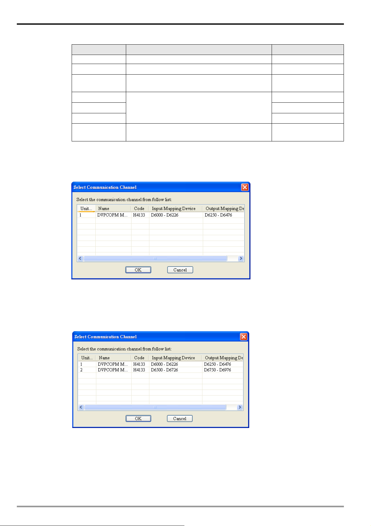
(4) Select “Network” => ”Online”, and the “Select Communication Channel” dialog box will appear. In
this example, if the connection with DVP-SV is in normal status, you will see the screen as below.
Communication speed between the PC and
DVP-SV
COmmuniction protocol between the PC and
DVP-SV
Communication mode between the PC and
DVP-SV
9,600 (bps)
1
ASCII
If there are more than one DVPCOPM-SL modules (less than 8) connected to the left side of
DVP-SV and supposed there are two connected in this example, after clicking on “Online”, you will
see the screen as below. The DVPCOPM-SL which is closest to DVP-SV is regarded the first module,
and so on.
(5) Select the DVPCOPM-SL which needs to establish the communication. Click on “OK” and start to
scan all the slaves on the network. If the network installation and power sup ply are normal, you will
12
see the screen as below.
DVP-PLC Application Manual
Page 15

CANopen Communication Module DVPCOPM-SL
(6) In normal condition, after the scan is over, you will find the master and all the slaves displayed in
CANopen network, as below .
z Setting up parameters in CANopen master
Select “Network” => ”Master Parameter”, and you will see the dialog box as below.
DVP-PLC Application Manual
13
Page 16

CANopen Communication Module DVPCOPM-SL
Work Mode: The work mode of DVPCOPM-SL. You can select either “Master Mode” or “Slave Mode”.
Cycle Period: The period of sending synchronous information.
Master’s heartbeat time: Time for DVPCOPM-SL to send out heartbeat.
After all the parameters are set up, click on “OK".
z Setting up parameters in CANopen slave
Take the parameter settings in ASD-B for example:
(1) Double click on ASD-B, and you will see the dialog box as below.
14
(2) Relevant parameter settings
Error Control Protocol: In the “Node Configuration…” page, clic k on “Error Control Protocol”, and
you will see the dialog box appearing as below.
DVP-PLC Application Manual
Page 17

CANopen Communication Module DVPCOPM-SL
In this page, you can set up parameters for error control, e.g. “Master Consumer Timeout” and
“Node Heartbeat Producer Time”. Please note that the value of “Master Consumer Timeout" shall be
bigger than the value of “Node Heartbeat Producer T i me”. After you have set up the heartbeat function,
and the slave turns off-line and does not turn on-line within “Master Cosume r Timeout”, the master will
consider the slave off-line. If “Heartbeat" is selected, you cannot select “Node Guarding”. In
“Heartbeat consumer”, you can add devices into the node list. Add a device A, and the slave will be
able to monitor whether device A is on-line. Select a device and click on “Edit…” to modify the
“Consumer" and “Producer” value.
Auto SDO Configuration: In the “Node Configuration” page, click on “Auto SDO Configuration”,
and you will see the page as below.
Click on “Add” to edit Auto SDO. Click on “Edit” to modify the Auto SDO selected. Please note that
the Auto SDO cannot be longer than 8 bytes, and every slave is able to posses maximum 20 auto
SDOs.
PDO mapping: In the “Node Configuration…” page, select a TxPDO or RxPDO in “Configured
DVP-PLC Application Manual
15
Page 18

CANopen Communication Module DVPCOPM-SL
PDO” and click on “PDO Mapping”, and you will enter the “PDO Mapping…” page as below. You can
add the parameters in “Available Object s from EDS file” into “Mapped Objects”. The total length of the
parameters added in each PDO cannot exceed 8 bytes. After the configuration is completed, click on
“OK”.
In the “Node Configuration…” page, click on “Properties” to enter the "PDO Properties” page and
modify COB-ID and Tran smit type. After the configuration is completed, click on “OK”. In the “Node
Configuration…” page, click on “Define PDO” to self define RxPDO ir TxPDO.
In this example, we adopt the default configuration. Finally, click “OK” in the “Node
Configuration…” page.
16
z Node List Setting
DVP-PLC Application Manual
Page 19

CANopen Communication Module DVPCOPM-SL
(1) Double click on “DVPCOPM Master” icon, and you will see the “Node List Setting” dialog box as
below.
(2) In this example, first select DVP-SS/SA/EH PLC at Node 003 and click on > to add this node into
the node list. After this, sel ect Node 003 in the node list, and you wi ll be able to see how the I/O dat a
correspond to D registers in DVP-SV from the Output Table and Input Table below.
(3) Add also Node 002 into the node list, and you will be able to see how the I/O data correspond to D
DVP-PLC Application Manual
17
Page 20

CANopen Communication Module DVPCOPM-SL
registers in DVP-SV from the Output Table and Input T able below. Click on “OK” to complete setting
up the node list.
z Downloading the data to the master
Select “Network“ => “Download” to download the configuration data to DVPCOPM-SL master. If
the PLC is in RUN status at this moment, you will be given a warning saying that you have to stop the
operation before the download.
Click on “OK” to stop the PLC and start to download the data to the master.
After the download is completed, you will be given another warning, askin g you if you would li ke to
18
run the PLC again. Click on “OK” to restart the PLC program, or click o n “Cancel” to stop the PLC.
DVP-PLC Application Manual
Page 21

CANopen Communication Module DVPCOPM-SL
4.4 Saving the Configuration Data
Select “File” => "Save” to save the current configuration data.
4.5 CANopen Network Control
In this section, we will introduce how to compile WPL program and control CANopen network.
z Target:
1. When SW0 on Slave 3 is closed, the servo drive on Slave 2 will start to run.
2. When SW0 on Slave 3 is open, the servo drive on Slave 2 will stop.
3. When the status of SW1 and SW2 on Slave 3 is switched, the running speed of servo drive on Slave
2 can be modified.
4. When the servo drive is running, the signal LED on Slave 2 will be On.
5. When the servo drive stops, the signal LED on Slave 2 will be Off.
z The program in DVP-SV MPU (master):
M1002
SET M0
M0
MOV D6032
MOV D6282
END
z Program explanations:
nd
1. The 2
row of the program indicates sending the content of D256 in DVP-SA (mapped on D6032 of
DVP-SV) to the control word (Multi-Function Digital Input, mapped on D62 86 of DVP-SV) of the serv o
drive.
rd
2. The 3
row of the program indicates sending the output status of the servo drive (Multi-Function
Digital Output, mapped on D6036 of DVP-SV) to D0 in DVP-SA (mapped on D6282 of DVP-SV).
z The program in DVP-SA MPU (slave):
M1002
MOV H
SET M1120
D6036
C6
D6286
D6286
D1120
D
M0
M10
DVP-PLC Application Manual
RST
SET M0
MOV K2 X20
MOV K2M10
END
M1143
D256
D0
Y0
19
Page 22

CANopen Communication Module DVPCOPM-SL
z Program explanations:
1. The first 3 rows of the program set up the communication format between DVP-SA and IFD9503,
which is 115,200bps, 7E1-ASCII; communication port is COM2.
2. When M0 = On, send the input status of X20 ~ X28 on DVP-08ST to D256, and send the dat a in b0 ~
b15 of D0 to M10 ~ M25.
3. When D0 = 1, M10 will be On, and Y0 on DVP-SA MPU will output.
5 Sending SDO, NMT and Reading Emergency by Ladder Diagram
5.1 The Principle
See the chart below for sending SDO by WPL program:
SDO request message from master
PORT2PORT
1
D
DVPCOPM DVP28SV
B
SDO request message
(PLC -> COPM)
SDO response message
(COPM -> PLC)
RUN
STOP
A
DVP28SVDVPCOPM-SL
SDO response message from slave
C
VFD-B
IFD9503
A: DVP-SV sends out request message to DVPCOPM-SL (master).
B: DVPCOPM-SL (master) sends out request message to the target equipment.
C: The target equipment processes the request message and sends the response message to
DVPCOPM-SL.
D: DVP-SV receives SDO, NMT and Emergency data.
5.2 Structure of SDO Request Message
You can edit SDO, NMT and Emergency in “request message editing are a”. Take the first DVPCOPM-SL
master placed on the left hand side of DVP-SV for example. See the table b elo w for the corresp ondi ng rel eation
between “request message editing area” and “response message editing area” and the devi ces in PLC.
20
DVP-PLC Application Manual
Page 23

CANopen Communication Module DVPCOPM-SL
PLC device Editing area Editing length
D6000 ~ D6031 SDO response message and Emergency response message 64 bytes
D6250 ~ D6281
See the table below for the format of SDO request message:
SDO request message, NMT service message and Emerg ency
request message
64 bytes
PLC device
D6250 ReqID Command
D6251 Reserved Size
D6252
D6253 High byte of main index Low byte of main index
D6254 Reserved Sub index
D6255 Datum 1 Datum 0
D6256 Datum 3 Datum 2
D6257 ~ D6281
z Command: Fixed to “01Hex”.
z ReqID: The request ID. Whenever an SDO request message is sent out, the message will be given a ReqID
for CANopen master to identify. For the next request message to be sent out, you have to change the ID
number. Ran ge of ReqID: 00Hex ~ FFHex.
z Size: The length of the message. Max. 8 bytes. Unit: byte.
z MAC ID: The node address of the target equipment on CANopen network.
z Ty pe: In SDO request message, 01Hex refers to SDO read message service; 02Hex refers to SDO write
Message Header
Message Data
15 14 13 12 11 10 9 8 7 6 5 4 3 2 1 0
Request Message
Type MAC ID
Reserved
message service; 4FHex refers to read 1 byte of data; 60Hex refer to write 1/2/4 byte(s) of data; 80Hex refers
to end SDO command. For example, if the type is 02Hex in SDO request message, it will become 60Hex for
SDO response message when the writing of data is successful.
z Status code:
Status code Explanation
0 No data transmission request
1 SDO data transmission is successful.
2 SDO data is being transmitted.
3 Erro r: SDO transmission time-out
4 Erro r: Illegal command
5 Erro r: Size of request message is illegal.
6 Erro r: Size of response message is illegal.
7 Erro r: Equipment to be sent messages is busy.
8 Erro r: Illegal type
9 Error: Incorrect node address
0A Error message (See the error code for SDO response message)
0B ~ FF Reserved
5.3 Structure of NMT Service Message
You can send the NMT request message to D6250 ~ D62 81, and t he slave will not re spond with a me ssage.
DVP-PLC Application Manual
21
Page 24

CANopen Communication Module DVPCOPM-SL
PLC device
D6250 ReqID Command
D6251 Reserved Size (fixed to 04Hex)
D6252
D6253 Reserved NMT service code
D6254
z Command: Fixed to “01Hex”.
z ReqID: The request ID. Whenever an NMT req uest message is sent out, the message will be given a ReqID
for the CANopen master to identify. For the next NMT request message to be sent out, you have to change
the ID number. Range of ReqID: 00 Hex ~ FFHex.
z MAC ID: The node address of the target equipment on CANopen network.
z NMT service code
z 01Hex: Enable remote node; 02Hex: Disable remote node; 80Hex: Enter pre-operational statu s; 81Hex:
Reset application; 82Hex: Reset communication
Example: If you would like to stop node 03 equipment on CANopen network, you have to set NMT servi ce
Message Header
Message Data
15 14 13 12 11 10 9 8 7 6 5 4 3 2 1 0
Type (fixed to 03Hex) MAC ID
Request Message
Reserved MAC ID
code to “02Hex” and MAC ID to “03".
5.4 Structure of Emergency Request Message
See the table below for the format of Emergency request message:
PLC device
D6250 ReqID Command
D6251 Reserved Size (fixed to 0)
D6252
D6253 ~ D6281 Message Data Reserved
See the table below for the format of Emergency response message:
PLC device
D6000 ReqID Status
D6001 Reserved Size (2A Hex)
D6002
D6003 Total number of data Number of data stored
D6004 Datum 1 Datum 0
D6005 Datum 3 Datum 2
D6006 Datum 5 Datum 4
D6007 Datum 7 Datum 6
D6008 ~ D6011 Emergency2
D6012 ~ D6015 Emergency3
D6016 ~ D6019
Message Header
Message Header
Message Data
15 14 13 12 11 10 9 8 7 6 5 4 3 2 1 0
Type (fixed to 04Hex) MAC ID
15 14 13 12 11 10 9 8 7 6 5 4 3 2 1 0
Type (04Hex) MAC ID
Request Message
Response Message
Emergency4
22
DVP-PLC Application Manual
Page 25

CANopen Communication Module DVPCOPM-SL
PLC device
Response Message
15 14 13 12 11 10 9 8 7 6 5 4 3 2 1 0
D6020~ D6023 Emergency5
D6024~ D6031 Reserved
z Command: Fixed to “01Hex”.
z ReqID: The request ID. Whenever an Emergency message is sent out, the message will be given a ReqID for
the CANopen master to identify. For the next Emergency message to be sent out, you have to change the ID
number. Ran ge of ReqID: 00Hex ~ FFHex.
z MAC ID: The node address of the target equipment on CANopen network.
z Total number of data: The total number of Emergency messages CANopen master receives.
z Number of data stored: The latest number of Emergency messages CANopen master receives. (Every slave
gives less than 5 messages.)
Note:
z CANopen master can only send out 1 SDO, NMT or Emergency request message to one e quipment at a
time.
z When you use WPL program to send out SDO, NMT or Emergency request messages, we recommend you
clear the “request message editing area” and “response message editing area” to 0.
5.5 Application Examples
In this section, we will illustrate how to compile a WPL program to send out SDO and NMT messages or
readEmergency request messages.
Example I
z Target:
When M0 = On, read the content of index 2021, sub index 4 (i.e. actual output value of AC motor
drive) in IFD9503.
DVPCOPM DVP28SV
RUN
CAN+
SHLD
CAN-
STOP
GND
Node 1
Master
CANop e n
Node 2
DVP-PLC Application Manual
IFD9503
RS-485
RJ12
VFD-B
23
Page 26
CANopen Communication Module DVPCOPM-SL
Required settings in DVPCOPM-SL:
Parameter Setting Explanation
Node address 01 Set the node address of DVPCOPM-SL to “01”.
Baud rate 1 Mbps
Required settings in IFD9503:
Parameter Setting Explanation
Node address 02 Set the node address of IFD9503 to “02”.
Baud rate 1 Mbps
Required settings in VFD-B AC motor drive:
Parameter Setting Explanation
02-00 04 The main frequency is operated by RS-485 interface.
02-01
09-00 01 Communication address of VFD-B: 01
09-01 03 Baud rate: 38,400 bps
09-04 03 Modbus RTU mode, format <8, N, 2>
03
Set the communication speed between DVPCOPM-SL and
bus to “1 Mbps”.
Set the communication speed between IFD9503 and bus to
“1 Mbps”.
The running command is operated by communication
interface. Operation by keys is valid.
Devices in PLC:
PLC device Content
SDO request
message
editing area
SDO response
message
editing area
15 14 13 12 11 10 9 8 7 6 5 4 3 2 1 0
D6250 0101Hex ReqID = 01Hex Command = 01Hex
D6251 0004Hex Reserved Size = 04Hex
D6252 0102Hex Type = 01Hex MAC ID = 02Hex
D6253 2021Hex High byte of index = 20Hex Low byte of index = 21Hex
D6254 0004Hex Reserved Sub index = 04Hex
D6000 0101Hex ReqID = 01Hex Status = 01Hex
D6001 0006Hex Reserved Size = 06Hex
D6002 4B02Hex Type = 4BHex MAC ID = 02Hex
D6003 2021Hex High byte of index = 20Hex Low byte of index = 21Hex
D6004 0004Hex Reserved Sub index = 04Hex
D6005 0100Hex Datum 1= 01Hex Datum 0 = 00Hex
Explanation
0100Hex in D6005 refers to the actual output frequency of the AC motor drive is 2.56Hz.
z PLC program
24
M1002
ZRST
ZRST D6250 D6281
D6000 D6031
Reset response message editing area
and request message editing area.
DVP-PLC Application Manual
Page 27

CANopen Communication Module DVPCOPM-SL
M0
MOV H0101 D6250
MOV H0004 D6251
MOV H0102
MOV
H2021
D6252
D6253
MOV H0004 D6254
ReqID = 01, Command = 01
Size = 04
Type = 01, MAC ID = 02
Index = 2021
Sub index = 04
END
z Program explanation
1. The program first reset the SDO request message editing area and SDO response message
editing area to 0.
2. When M0 = On, CANopen master will send out SDO request message and read the contents in
index 2021, sub index 4 of the target equipment (at node address 02). If the communication is
successful, the slave will return with the response message.
3. When M0 = On, CANopen master will send out request message only once. If you would like it to
send out messages again, you will have to change the ReqID.
4. The messages returned from the target equipment are stored in D6000 ~ D6005.
Example II
z Target:
When M0 = On, set the content in index 2047, sub index 2 (i.e. the control word of the target
temperature) in IFD9503 to 0104Hex (i.e. 26.0°C). Please note that you have to write 0401Hex into
D6255 of the PLC.
DVPCOPM DVP28SV
RUN
CAN+
SHLD
CAN-
STOP
GND
Node 1
Master
CANopen
Node 2
DVP-PLC Application Manual
IFD9503
RS-48 5
PV
SV
SET
AT
OUT ALM1 ALM2
DTA
DTA4848
°C
°
F
25
Page 28

CANopen Communication Module DVPCOPM-SL
Required settings in DVPCOPM-SL:
Parameter Setting Explanation
Node address 01 Set the node address of DVPCOPM-SL to “01”.
Baud rate 1 Mbps
Required settings in IFD9503:
Parameter Setting Explanation
Node address 02 Set the node address of IFD9503 to “02”.
Baud rate 1 Mbps
Required settings in DTA temperature controller:
Parameter Setting Explanation
D
e
On C WE: Enable/disable communication write-in
ASCII C-SL: Select ASCII or RTU format
1 C NO: Set up communication address
38400 BPS: Set up communication speed
7 LENGTH: Set up data length
E PARITY: Set up parity bit
1 STOP BIT: Set up stop bit
°C UNIT: Select temperature unit, °C or °F
Set the communication speed between DVPCOPM-SL and the bus
to “1 Mbps”.
Set the communication speed between IFD9503 and the bus to “1
Mbps”.
Devices in PLC
PLC device Content
SDO request
message
editing area
SDO response
message
editing area
Explanation
15 14 13 12 11 10 9 8 7 6 5 4 3 2 1 0
D6250 0101Hex ReqID = 01Hex Command = 01Hex
D6251 0006Hex Reserved Size = 06Hex
D6252 0202Hex Type = 02Hex MAC ID = 02Hex
D6253 2047Hex High byte of index = 20Hex Low byte of index = 47Hex
D6254 0002Hex Reserved Sub index = 02Hex
D6255 0401 Hex Datum 1= 04Hex Datum 0= 01Hex
D6000 0101Hex ReqID = 01Hex Status = 01Hex
D6001 0004Hex Reserved Size = 04Hex
D6002 6002Hex Type = 60Hex MAC ID = 02Hex
D6003 2047Hex High byte of index = 20Hex Low byte of index = 47Hex
D6004 0002Hex Reserved Sub index = 02Hex
26
DVP-PLC Application Manual
Page 29

z PLC program
M1002
M0
CANopen Communication Module DVPCOPM-SL
ZRST D6000 D6 03 1
Reset response message editing area
and request message editing area.
ZRST D6250 D6 28 1
MOV H0101 D6250
ReqID = 01, Command = 01
MOV H0006 D6 251
MOV
MOV
MOV
MOV
END
H0202
H2047
H0002 D6254
H0401 D6255
D6252
D6253
Size = 06
Type = 02, MAC ID = 02
Index = 2047H
Sub index = 02
Target temperature for DTA: 0 104H
z Program explanation
1. The program first reset the SDO request message editing area and SDO response message
editing area to 0.
2. When M0= On, CANopen master will send out SDO request message and write 0104Hex into
index 2047, sub index 2 of the target equipment (at node address 02). If the communication is
successful, the slave will return with the response message.
3. When M0 = On, CANopen master will send out request message only once. If you would like it to
send out messages again, you will have to change the ReqID.
4. The messages returned from the target equipment are stored in D6000 ~ D6 004.
6 LED Indicator & Trouble-shooting
DVPCOPM-SL has three LED indicators and a digit al display on it. POWER LED display s whether the powe r
supply of DVPCOPM-SL is normal. RUN LED and ERR LED display the current operational status. The digital
display shows the node address of DVPCOPM-SL and error messages from the slave.
DVPCOPM
POWER
RUN
ERR
DVP-PLC Application Manual
27
Page 30
CANopen Communication Module DVPCOPM-SL
6.1 POWER LED
LED status Indication How to correct
On Power is abnormal. Check the power supply of DVPCOPM-SL.
Green light On Power is normal. --
6.2 RUN LED
LED status Indication How to correct
Off No power
Green light single
flash
Green light
blinking
Green light steady
on
DVPCOPM-SL in STOP status -DVPCOPM-SL in pre-operational
status
DVPCOPM-SL is operational
status
Check the power of DVPCOPM-SL and make
sure the connection is normal.
--
--
6.3 ERR LED
LED status Indication How to correct
Off Normal -Red light double
flash
Red light single
flash
Red light steady
on
Error control event See the indication from the digital display.
Bus error exceeds the warning
limit.
Bus-off
6.4 Codes in Digital Display
z DVPCOPM-SL as master:
Code Indication How to correct
0 ~ 7F
F1 No slave configured in node list
F2
F3 DVPCOPM-SL in error status Check if the wiring of DVPCOPM-SL is correct.
F4 Bus-off is detected.
F5 Incorrect DVPCOPM-SL settings
F6
F7 Internal error: GPIO check
F8 Internal error: memory check
The node address of DVPCOPM-SL
when in normal operation.
The data are being downloaded to
DVPCOPM-SL.
Internal error: manufacturing
process
Check if the network connection and operation are
normal.
Check if the bus connection is normal and
re-power DVPCOPM-SL.
-Re-configure the node list and download it to
DVPCOPM-SL.
--
Make sure the communication cable is in normal
operation, and all the nodes on the network work
in the same baud rate. Re-power DVPCOPM-SL.
Check the settings of node address and baud
rate and make sure the settings are correct.
Re-power DVPCOPM-SL. If the error still exists,
change to a new DVPCOPM-SL.
28
DVP-PLC Application Manual
Page 31

CANopen Communication Module DVPCOPM-SL
Code Indication How to correct
F9 Low voltage is deteced.
FA
FB
FC
E0
E1
E2
E3 Auto SDO download failed. Check and make sure auto SDO is correct.
E4 PDO parameter setting has failed. Make sure the PDO parameter setting is legal.
E5 Error in key parameter setting.
E6
E7
E8
The firmware of DVPCOPM-SL is
in error status.
The sending buffer in
DVPCOPM-SL is full.
The receiving buffer in
DVPCOPM-SL is full.
DVPCOPM-SL receives
Emergency message sent by the
slave.
PDO data length returned from the
slave is not consistent with the
length set in the node list.
PDO message from the slave has
not been received.
The slave does not exist in the
network.
The slave's error control is
timed-out.
Master/slave node address is
repeated.
Check and make sure the power of
DVPCOPM-SL works normally.
Re-power DVPCOPM-SL.
Make sure the bus works normally and re-power
DVPCOPM-SL.
Make sure the bus works normally and re-power
DVPCOPM-SL.
Read relevant information through PLC MPU or
Delta CANopenBuilder software.
Reset the PDO data length in the slave and
download the new setting to DVPCOPM-SL.
Check and make sure the setting is correct.
Make sure all the slaves connected are
consistentwith the slaves set.
Make sure the power of the slave and the
network connection work normally.
Reset the node address and make sure the new
address is not a repeated one.
z DVPCOPM-SL as slave:
Code Indication How to correct
0 ~ 7F
A0
A1
A3
B0 Heartbeat timed-out Re-connect DVPCOPM-SL to the network.
B1
F4 Bus-off is detected
FB
FC
The node address of DVPCOPM-SL
when in normal operation.
The parameters in DVPCOPM-SL is
being initialized.
DVPCOPM-SL is in pre-operational
status.
The data are being downloaded to
DVPCOPM-SL.
PDO data length returned from the
slave is not consistent with the
length set in the node list.
The sending buffer in
DVPCOPM-SL is full.
The receiving buffer in
DVPCOPM-SL is full.
--
--
--
--
Reset the PDO data length in the slave and
download the new setting to DVPCOPM-SL.
Make sure the communication cable is in normal
operation, and all the nodes on the network work
in the same baud rate. Re-power DVPCOPM-SL.
Make sure the bus works normally and re-power
DVPCOPM-SL.
Make sure the bus works normally and re-power
DVPCOPM-SL.
DVP-PLC Application Manual
29
Page 32

CANopen Communication Module DVPCOPM-SL
MEMO
30
DVP-PLC Application Manual
 Loading...