

Delta Electronics DIAVH-IPC003101, DIAVH-IPC005102, DIAVH-IPC005100, DIAVH-IPC005101, DIAVH-IPC003103 User Manual
...
Embedded industrial
computer
User manual
The model you choose:
□ DIAVH-IPC003100
□ DIAVH-IPC005100
□ DIAVH-IPC003101
□ DIAVH-IPC005101
□ DIAVH-IPC003102
□ DIAVH-IPC005102
□ DIAVH-IPC003103
□ DIAVH-IPC005103
□ DIAVH-IPC003104
□ DIAVH-IPC005104
□ DIAVH-IPC003105
□ DIAVH-IPC005105
version:Ver. A02

Disclaimer
This manual is only for Delta Electronics, Inc, no copyright without
permission .the contents of this manual are not representative of the
manufacture’s commitment ,due to the continuous improvement of products,
we reserve the right to change the manual, please forgive that if no information
in advance.
In no event will the manufacture be liable for direct. indirect.
Special .incidental or consequential damages. arising out of improper
installation or use. Or inability to use the product or documentation.
Guarantee Clause:
The warranty on the product lasts for 18 months, if the user has additional
requirements ,the contract sighed between the two sides shall prevail.
Trademarks
All the trademarks mentioned in this manual are registered trademarks of their
respective companies.
AMI® is the registered trademark of AMI Company.
Intel®, Celeron®, Pentium®,Atom are the registered trademarks of Intel.
NetWare® is the registered trademark of Novell Inc.
PS/2 and OS/2 are the registered trademarks of International Business
Machines
Windows 7, windows XP, Windows 8 are the registered trademarks of
Microsoft

Safety Instructions
• Please read the user manual carefully before using the product, and
carefully keep it for future reference.
• Before connecting power supply to the product, please confirm the voltage
is compliant with the requirement of the device.
• To avoid electric shock or damage to the product, please unplug the power
cord from the socket before cleaning the device by wet rag.
• Please do not use liquid or aerosol cleaner to clean up the device.
• To avoid short circuit or fire, please do not let any liquid get into or splash
into the product.
• For a device which needs to use power cord, there must be an
easy-to-reach power socket around the device.
• Please do not use the product in a damp environment.
• Before installation, please make sure the device is placed on a solid
surface; accidental drop or tipping may cause malfunction or damage to
the device.
• Before you connect or unplug any signal cable, make sure all power cords
are unplugged in advance;
• To avoid unnecessary damage caused by frequent power-on/off, wait at
least 30 seconds after turning off the computer before re-turning on the
computer.
• If the product will not be used for a long time, please disconnect the power
cord, to avoid damage to the product by transient voltage.
• If the product needs to be upgraded, installed or dismantled, please
implement all the operation on an ESD workstation, for some precision
devices are sensitive to ESD;
• Ensure excellent heat dissipation and ventilation of the system.
Please do not open or dismantle the device by yourself. For the sake of
safety, this device can only be opened by a professional maintenance
person.

Packing List
• A fanless industrial Computer
• 1*AC 100V~240V to DC+12V/5A power adapter
• 1*AC220V power cable
• 2*Mounting Bracket & 6*Screw
• 1*Driver CD & manual
• 1*Certification,1*packing list

Content
1.Product Introduction ......................................................................... 1
1.1 Brief introduction ........................................................................................ 1
1.2 Product specifications ................................................................................ 1
1.3 I/O ................................................................................................................. 3
2.Application planning ......................................................................... 4
2.1 Transportation ............................................................................................. 4
2.2 Storage Requirements ............................................................................... 4
2.3 Unpack and check the delivered equipment .......................................... 4
3.Installation instructions .................................................................... 6
3.1 Product outline ............................................................................................ 6
3.2 Product assembly ....................................................................................... 6
3.3 Product Dimension ..................................................................................... 7
4.Interface Definition ........................................................................... 8
4.1 USB port ...................................................................................................... 8
4.2 Ethernet ....................................................................................................... 9
4.3 Standard DB9.............................................................................................. 9
4.4 Standard VGA ............................................................................................. 9
4.5 Standard HDMI A Type ............................................................................ 10
4.6 Power ......................................................................................................... 10
5. Appendix ............................................................................................ 11
5.1 Host BIOS settings ................................................................................... 11
5.1.1 Main ............................................................................................... 11
5.1.2 CSTIPC ......................................................................................... 11
5.1.3 Advanced ...................................................................................... 13
5.1.4 Chipset .......................................................................................... 14
5.1.5 Boot ............................................................................................... 14
5.1.6 Security ......................................................................................... 15
5.1.7 Save & Exit ................................................................................... 16
5.2 Driver software installation ...................................................................... 17
5.2.1 Chipset driver installation ............................................................ 17

5.2.2 On board graphics card driver installation ................................ 17
5.2.3 On board sound card driver installation .................................... 17
5.2.4 On board network card driver installation ................................. 17
5.3 Trouble & Trouble shooting ..................................................................... 18

- 1 -
1.Product Introduction
1.1 Brief introduction
DIAVH-IPC00X10X is a low-power-consumption, high-performance and
fanless embedded industrial computer, with material of high-strength and
elegant al-alloy and the high-density al-alloy radiator.
This product has low power consumption Intel Core I3-4030U / I5-4200U
on board, 4GB DDR3L RAM,max to 8GB (optional), and it has rich I/O
interfaces and fully-sealed fanless design, supporting Windows 7/ 8.1/10 Linux
and so on.
This product can be used in the field of mechanical equipment,intelligent
transportation, industrial automation control and other different embedded
solutions.
1.2 Product specifications
Item
Definition
Main
function
processor
DIAVH-IPC003100/01/02/03/04/05: Intel® Core
I3-4030U
DIAVH-IPC005100/01/02/03/04/05: Intel® Core
I5-4200U
memory
4GB DDR3L RAM
display
Integrated Intel® HD 4400,200-1000MHz
storage
SSD 512GB
ethernet
2*RTL8111E GbE
audio
1*Line out
expansion
Mini-PCIE bus expansion, support Wifi ,Bluetooth
I/O
6*serial port COM1(RS232), COM2(RS232),
COM3(RS232), COM4(RS232),
COM5(RS232), COM6(RS422/RS485)
2*USB2.0, 4*USB3.0
2* Intel I211
1*VGA
1*HDMI
1*Line out

- 2 -
Item
Definition
perform
ance
Dimension
DIAVH-IPC003100/01/02/03/04/05:
212.4mm(L)×210mm(W)×71.6 mm(H);
DIAVH-IPC005100/01/02/03/04/05:
212.4mm(L)×210mm(W)×71.6 mm(H);
structure
Material: high-strength Al-alloy heat
dissipating plate
color:black
Heat dissipation:fanless design
weight
DIAVH-IPC003100/01/02/03/04/05 : NW :
2.75Kg;GW:3.5Kg
DIAVH-IPC005100/01/02/03/04/05 : NW :
2.75Kg;GW:3.5Kg
Temp
Operationg temp:-10°C ~ 50°C
Storage temp:-20°C ~ 60°C
Humidity
90% @ 40°C(non-condensing)
EMC
Limit of radio disturbance meets
GB9254-1998 standard Class A
Immunity meets the limits of GB/T
17618-1998 standard
Reliability
MTBF≥5000h
MTTR≤0.5h
safety
Meets basic requirements of GB4943
Mechanic
environment
compatibility
Anti-vibration: 5-19Hz/1.0mm amplitude;
19-200Hz/1.0g, acceleration
Anti-shock: 10g acceleration, 11ms duration
Power
100~240VAC/50~60Hz(with adapter);
9~24VDC or 9~36VDC optional(no
adapter);
Power consumption: 16 W(standby);
Power consumption: 20.4 W(running
MaxPower 100%);

- 3 -
1.3 I/O
DIAVH-IPC003100/01/02/03/04/05(DIAVH-IPC005100/01/02/03/04/05):
Picture 1-1

- 4 -
2.Application planning
2.1 Transportation
Well-packaged products are suited for transportation by truck, ship, and
plane. During transportation, products should not be put in open cabin or
carriage. During transshipping, products should not be stored in open air
without protection from the atmospheric conditions. Products should not be
transported together with inflammable, explosive and corrosive substances
and are not allowed to be exposed to rain, snow and liquid substances and
mechanical force.
2.2 Storage Requirements
Products should be stored in package box when it is not used. And
warehouse temperature should be -20℃~70℃, and relative humidity should
be 20% ~ 85%. In the warehouse, there should be no harmful gas,
inflammable, explosive products, and corrosive chemical products, and strong
mechanical vibration, shock and strong magnetic field interference. The
package box should be at least 10cm above ground, and 50cm away from wall,
thermal source, window and air inlet
Caution!!!
Risk of destroying the device!
When shipping the PC in cold weather, please pay attention to the
extreme temperature variation. Under this circumstance, please make
sure no water drop (condensation) is formed on the surface or interior of
the device. If condensation is formed on the device, please wait for over
twelve hours before connecting the device.
2.3 Unpack and check the delivered equipment
Unpack the equipment
Pay attention to the following things when you unpack the equipment.
● Please take the advice not to throw away the original packaging material and
please retain to use it when the equipment should be transported again.
● Please put the document in a safe place. It will be used in the initial
adjustment of equipment and it is a part of the equipment.

- 5 -
● When you check the delivered equipment, please check whether it is
obviously damaged during the transportation.
● Please check whether the delivered parcel includes the whole equipment
and the accessories you ordered separately. If there is any discrepancy or
damaged during transportation, please contact our customer-service staff.
- 6 -
3.Installation instructions
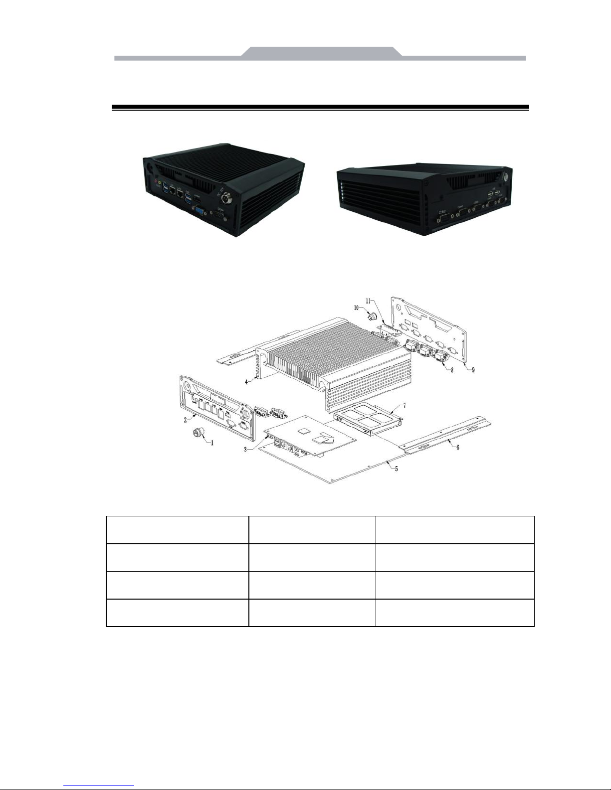
3.1 Product outline
Picture 3-1
3.2 Product assembly
Picture 3-2
1. on-off
2. front panel
3. motherboard
4. radiator
5. baseboard
6. installation support
7. harddisk support
8. COM
9. backplate
10. DC in-put
11. USB
- 7 -
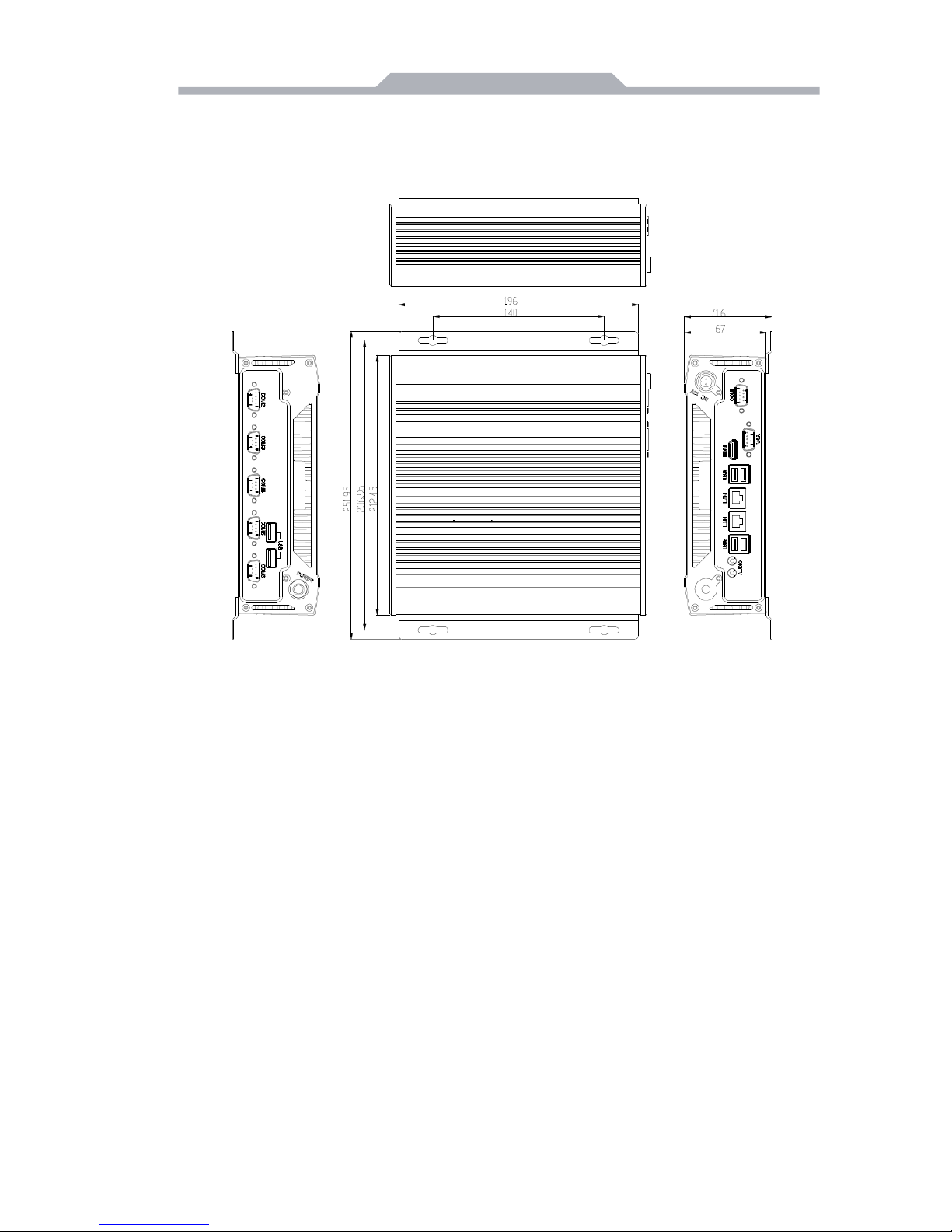
3.3 Product Dimension
DIAVH-IPC003100/01/02/03/04/05(DIAVH-IPC005100/01/02/03/04/05)
Picture 3-3

- 8 -
4.Interface Definition
4.1 USB port
There are 2 USB2.0 and 4 USB 3.0 on this product,following is the pin
definition:
USB1~2
USB2.0
Definition
1
+5V
2
USB Data-
3
USB Data+
4
GND
USB3~6
USB3.0
Definition
1
GND
2
D+
3
D-
4
VBUS
5
StdA_SSTX+
6
StdA_SSTX-
7
GND_DRAIN
8
StdA_SSRX+
9
StdA_SSRX-

- 9 -
4.2 Ethernet
There are 2 Ethernet 1000M on this product,following is the pin definition:
LAN1,LAN2
ACTLED
(Green light)
Netstat
LILED
(green/orange)
netstat
green
1000Mbps
Twinkle
With data
transmission
orange
100Mbps
Light off
No data
transmission
Light off
10Mbps
4.3 Standard DB9
COM1~4
Pin
Definition
RS-232
RS-485
RS-422
1
DCD#
T/R+
T/R+
2
RXD
T/R-
T/R-
3
TXD X RXD+
4
DTR# X RXD-
5
GND
GND
GND
6
DSR#
VCC (+5V
spare input)
VCC (+5V spare
input)
7
RTS# X X
8
CTS# X X
9
RI# X X
4.4 Standard VGA
VGA Display, its interface is 15 core type D VGA display socket.

- 10 -
VGA
pin
definition
pin
definition
1
Red
2
Green
3
Blue
4
N.C.
5
GND
6
Detect
7
GND
8
GND
9
+5V
10
GND
11
NC
12
DDCDATA
13
HSYNC
14
VSYNC
4.5 Standard HDMI A Type
HDMI
pin
definition
pin
definition
1
DATA2+
2
DATA2 shield
3
DATA2-
4
DATA1+
5
DATA1 shield
6
DATA1-
7
DATA0+
8
DATA0 shield
9
DATA0-
10
DATA1_CK+
11
DATA1_CK
12
DATA1_CK-
13
CEC
14
Reserved
15
SCL(DDC
16
SDA(DDC data)
17
DCC/CEC GND
18
+5V
19
Hot swap test
/
4.6 Power
This product support DC+12 V power in, together with power adapter, and
following is the power pin definition:
DC12V input
pin
definition
1
+12V
2
GND
- 11 -
5. Appendix
5.1 Host BIOS settings
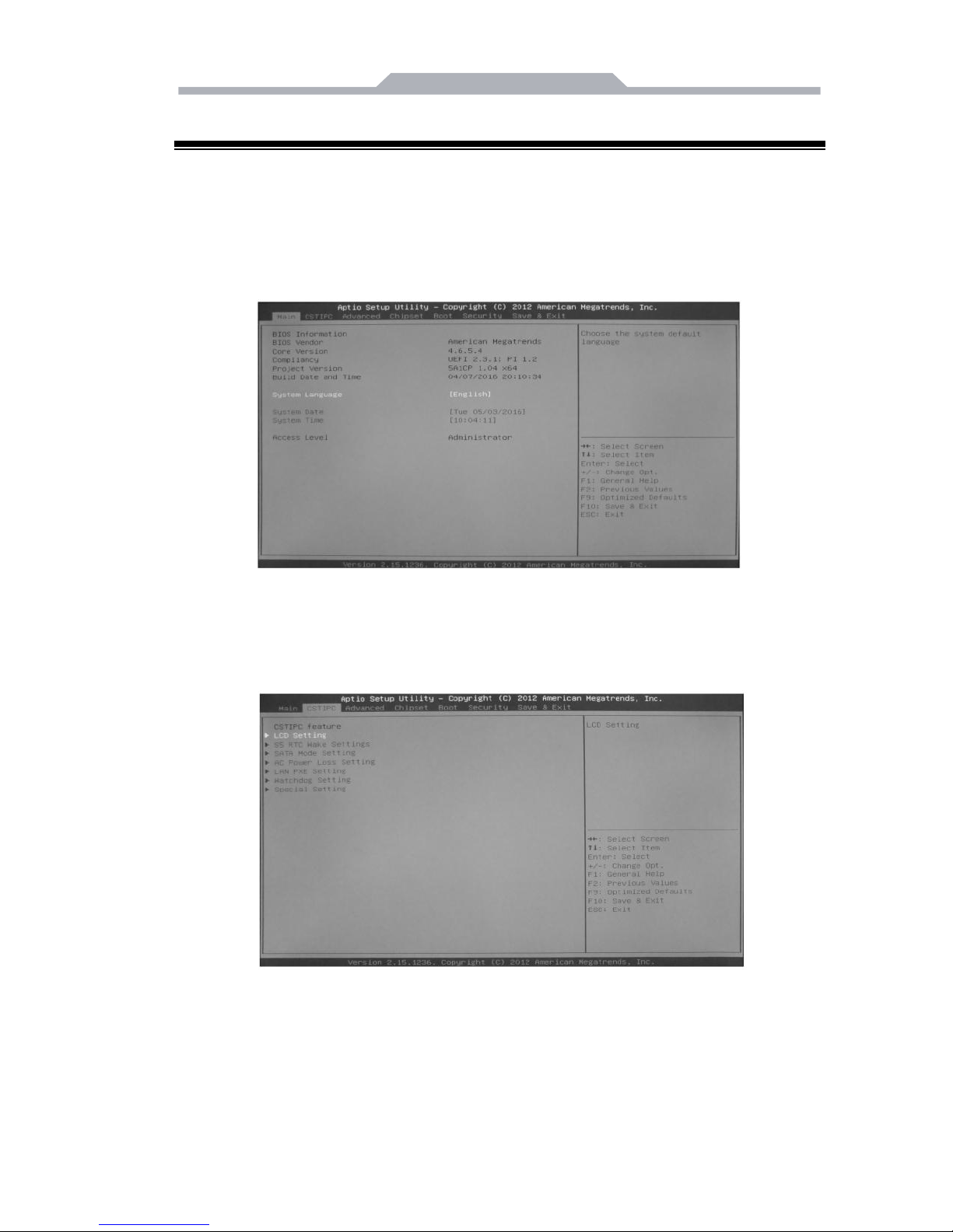
5.1.1 Main
Press F2 to boot, go into BIOS →CMOS, setting date and time as shown
in picture 5-1:
Picture 5-1
5.1.2 CSTIPC
Enter page of picture5-2, choose “LCD setting” to page of picture5-3
Picture 5-2

- 12 -
Picture 5-3
In “LCD Panel Type” options, you can change panel pc’ s original
resolution, if the resolution you choose is uncompatible with screen’ s real
resolution, may lead to unnormal showing.
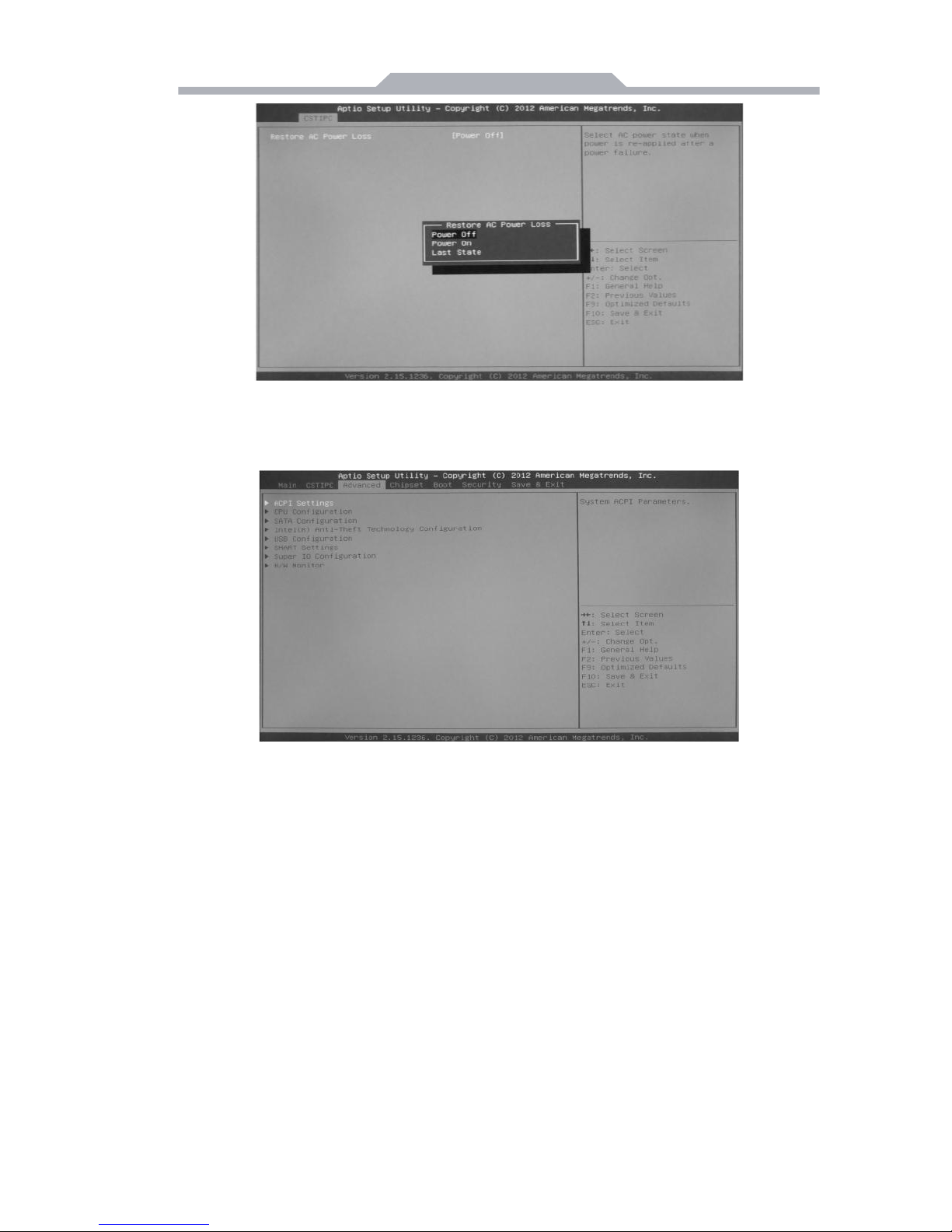
In page of picture 5-4, choose ”AC power Loss Setting” to enter “Restore
AC Power Loss” :
【Power off】Press switch to boot after power on,
【Power on】Auto boot after power on,
【Last Status】After power on, if illegal shutdown last time, the pc will
return last status ,if normal shutdown, pc will be in power on status.as shown in
picture 5-5:
Picture 5-4
- 13 -
Picture 5-5
5.1.3 Advanced
Picture 5-6
ACPI Settings;
CPU Configuration;
SATA Configuration SATA;
Intel (R) Anti-Theft Technology Configuration;
USB Configuration;
SMART Settings;
Super IO Configuration;
H/W Monitor;

- 14 -
5.1.4 Chipset
Here you can set I/O port,system memory,graphics memory,as shown in
picture 5-7:
Picture 5-7
5.1.5 Boot
The menu can set Num Lock’ s status when booting, or set storage’ s
boot program,firstly, choose first boot device in “Hard Drive BBS Priorities”,,
then choose it in “Boot Option #1”,press F4 to save and exit. choose “Hard
Drive BBS Priorities” to enter, as shown in picture 5-8.
Picture 5-8

- 15 -
Enter “Hard Drive BBS Priorities”, choose first boot device in “Boot
Option #1”,as shown in 5-9:
Picture 5-9
After last step, press “ESC” to return to last page,choose first boot
decvice in “Boot Option #1”again,as shown in picture 5-10,preess “F4” to
save, press “enter” to exit.
Picture 5-10
5.1.6 Security
This menu is used to set password to enter BIOS Setup and boot.as
shown in picture 5-11:

- 16 -
Picture 5-11
5.1.7 Save & Exit
Enter CMOS page,choose "Save & Exit" , as shown in picture 5 -12 :
Picture 5-12
Press“F3”to recover factory reset,press“F4”to save.

- 17 -
5.2 Driver software installation
5.2.1 Chipset driver installation
(1) En ter “Dr ive r \Chipset\”, double click “Intel _inf.ex e” .
(2) Follow notice, click “ n ex t st e p” a n d “ c ont i nu e ” .
(3) After installation, c ho ose “ Yes ” a nd “finish” in “ res tar t”, the
driver software would auto load after restart
.
5.2.2 On board graphics card driver installation
(1) Enter driver CD “Driver\ Graphic\
”,choose related OS files. double
click “setup. exe” with left key.
(2) Follow notice, click “ n ex t st e p” a n d “ c ont i nu e ” .
(3) After installation, c ho ose “ Yes ” a nd “finish” in “ res tar t”, the
driver software would auto load after restart
.
5.2.3 On board sound card driver installation
(1 ) En t er d riv e r C D “ D ri v e r \Audio\ ” .Choose related OS
files, dou b le c lic k “s e t up. e xe” with left key. Following
notice, cl i ck “ nex t s t e p” a nd “ c on t inu e ” .
(2) After installation, choos e “ Yes ” and “fini sh” in restart
options. the driver software would auto load after restart.
5.2.4 On board network card driver installation
(1) Enter driver CD “
Driver\
LAN\ ”,
Choose related OS files,
do u ble cl i c k “ s e tu p . ex e ” with left key. Following notice,
cl i ck “ ne x t s t e p” a nd “c o n ti n u e”.
(2) After installation, choose “Yes” and “finish” in restart options. the driver
software would auto load after restart.

- 18 -
5.3 Trouble & Trouble shooting
Common
Malfunction
Possible Reasons
Trouble shooting and solution
The device is
not operating
No power supply
Please check the power supply and the power
cable/connector
Improper device
operating
environment
1. Check the environment conditions
2. Please wait for 12 hours before powering on
the device shipped in cold day.
The external
display is
black
The display has not
been turned on
Turn on the display
Display output skip
to other display
channel
After enter OS(check light through “Num Lock”)
Use composite key “Ctrl+ALT+F1/F2/F3/F4” to
switchover video output between
VGA/DVI/LVDS/HDMI
The display is under
“power saving”
mode
Press any key on the keyboard.
The luminance
control is set to
“Black”
Increase the screen luminance by luminance
control. Please refer to the instructions of the
display for detailed information.
Power cable or
display cable is not
connected
1. Please check whether the power cable &
display cable is correctly connected with the
display, the system unit or the ground port。
2. Contact technique support if the screen
remains black after implementing the above
measures.
Incorrect
time or date
on PC
Incorrect BIOS
setting
Follow the power-on prompt and press the key to
enter the BIOS setup, adjust the time and date in
BIOS setup.
BIOS setting
is correct
while the
time and
date are not
correct
Insufficient backup
battery capacity
Replace the battery
USB device
has no
response
USB port is disabled
in BIOS
Use other USB ports or enable that port.
USB2.0 device is
connected while
USB 2.0 is disabled
Enable USB 2.0.
USB port is not
supported by the
operating system
1. Enable USB Legacy Support for the mouse &
keyboard (legacy USB is supported);
2. For other device, appropriate USB drivers are
required.

- 19 -
Common
Malfunction
Possible Reasons
Trouble shooting and solution
Boot device
not found
In booting priority of
the BIOS setting,
the device is not the
first priority or the
device is not include
in the booting device
Modify the booting priority of the device in the
Boot menu of BIOS setting or include that device
into the booting priority
No system
disk can be
found when
powering on
The HDD power
cable or data cable
is not connected
well
Check whether the power cable and the data
cable of the hard disk(the hard disk shall be
installed with operating system and is bootable)
are well connected
System files on the
hard disk are
damaged
Enter the system(usually WinPE system) with a
bootable disk check whether the system in the
hard disk is damaged. Reinstall the system if
necessary.
Plug and
play I/O card,
no I/O card is
detected, or
I/O card can
be used
when used
again
Poor contact of the
slot
Poor contact is usually caused by frequent
installation/ uninstallation of the PCI or ISA card,
unstable fixing or improper dust-proof
measures; please remove and install the card
for a few times or use another slot.
 Loading...