

Page 1
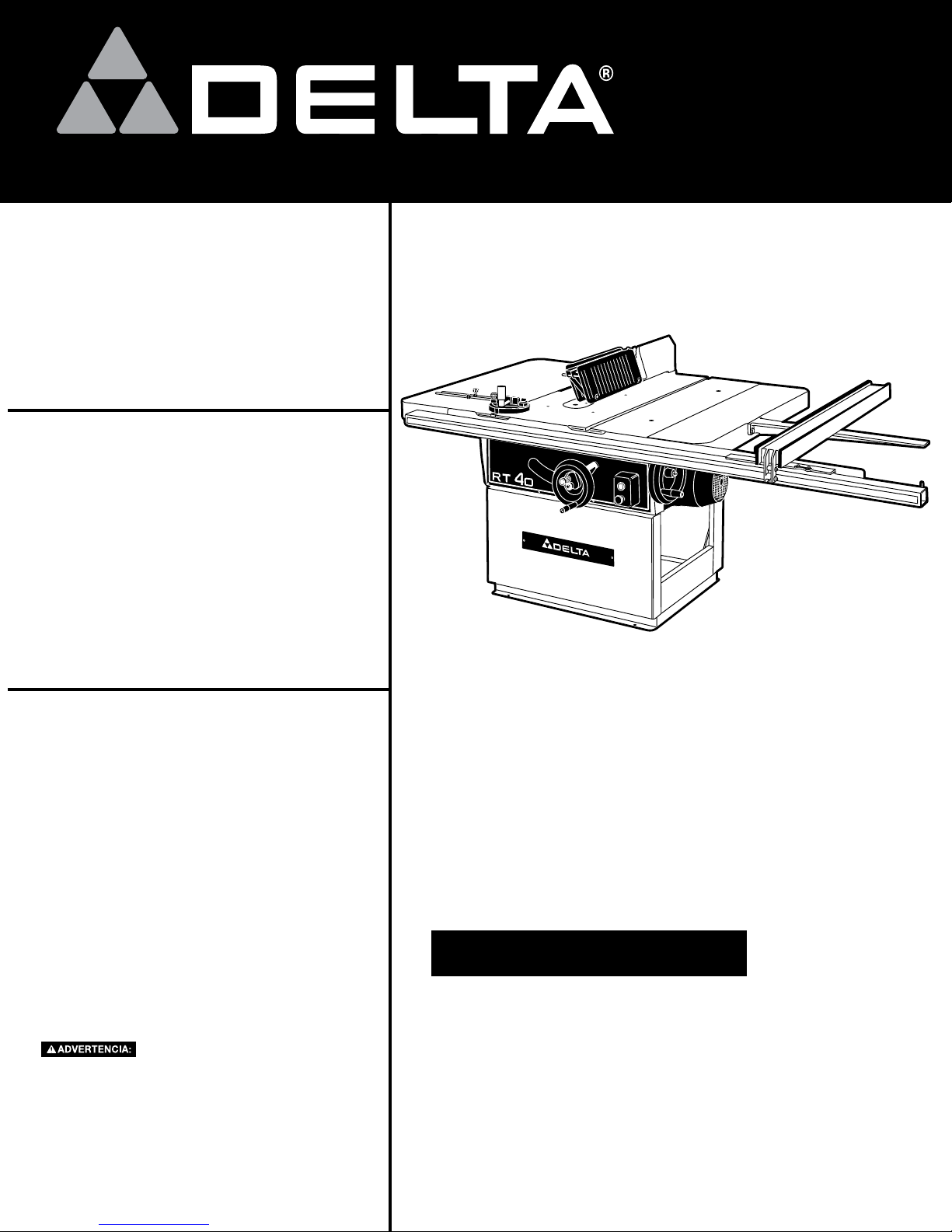
RT-40 14"/16"
Left Tilting
Arbor Saw
RT -40
355 y 406 mm
36-790
14 po/16 po
Scie circulaire
articulée à gauche
RT -40
Sierra de eje con
inclinación hacia la
izquierda de 355 y
406 mm (14”/16”)
Instruction Manual
Manuel d’utilisation
Manual de instrucciones
FRANÇAIS (27) ESPAÑOL (52)
INSTRUCTIVO DE OPERACIÓN, CENTROS
DE SERVICIO Y PÓLIZA DE GARANTÍA.
LÉASE ESTE INSTRUCTIVO
ANTES DE USAR EL PRODUCTO.
A26301 - 03-10-08
Copyright © 2006, 2008 Delta Machinery
www.deltaportercable.com
(800) 223-7278 - US
(800) 463-3582 - CANADA
Page 2

TABLE OF CONTENTS
IMPORTANT SAFETY INSTRUCTIONS ........................ 2
SAFETY GUIDELINES - DEFINITIONS ......................... 2
GENERAL SAFETY RULES ........................................... 3
ADDITIONAL SPECIFIC SAFETY RULES .................... 4
FUNCTIONAL DESCRIPTION .......................................7
CARTON CONTENTS ...................................................7
ASSEMBLY ..................................................................... 8
OPERATION ................................................................... 15
TROUBLESHOOTING .................................................... 25
MAINTENANCE .............................................................. 25
SERVICE ......................................................................... 26
ACCESSORIES ............................................................... 26
WARRANTY .................................................................... 26
FRANÇAIS ...................................................................... 27
ESPAÑOL ........................................................................ 52
IMPORTANT SAFETY INSTRUCTIONS
Read and understand all warnings and operating instructions before using any tool or
equipment. Always follow basic safety precautions to reduce the risk of personal injury. Improper operation,
maintenance, or modification of tools or equipment could result in serious injury and property damage. Our
tools and equipment are designed for certain applications. DO NOT modify and/or use this product for any
application other than that for which it was designed.
If you have any questions relative to its application DO NOT use the product until you have written Delta Machinery and we
have advised you. Contact us online at www.deltaportercable.com or by mail at Technical Service Manager, Delta Machinery,
4825 Highway 45 North, Jackson, TN 38305. In Canada,125 Mural St. Suite 300, Richmond Hill, ON, L4B 1M4)
Information regarding the safe and proper operation of this tool is available from the following sources:
• PowerToolInstitute,1300 Sumner Avenue, Cleveland, OH 44115-2851or online at www.powertoolinstitute.org
• NationalSafetyCouncil, 1121 Spring Lake Drive, Itasca, IL 60143-3201
• AmericanNationalStandardsInstitute, 25 West 43rd Street, 4 floor, New York, NY 10036 www.ansi.org - ANSI 01.1 Safety
Requirements for Woodworking Machines
• U.S.DepartmentofLabor regulations www.osha.gov
SAVE THESE INSTRUCTIONS!
SAFETY GUIDELINES - DEFINITIONS
It is important for you to read and understand this manual. The information it contains relates to protecting YOUR SAFETY
and PREVENTING PROBLEMS. The symbols below are used to help you recognize this information.
Indicates an imminently hazardous situation which, if not avoided, will result in death or serious injury.
Indicates a potentially hazardous situation which, if not avoided, could result in death or serious injury.
Indicates a potentially hazardous situation which, if not avoided, may result in minor or moderate injury.
Used without the safety alert symbol indicates a potentially hazardous situation which, if not avoided, may
result in property damage.
CALIFORNIA PROPOSITION 65
Some dust created by power sanding, sawing, grinding, drilling, and other construction activities
contains chemicals known to the State of California to cause cancer, birth defects or other
reproductive harm. Some examples of these chemicals are:
• leadfromlead-basedpaints,
• crystallinesilicafrombricksandcementandothermasonryproducts,and
• arsenicandchromiumfromchemically-treatedlumber.
Your risk from these exposures varies, depending on how often you do this type of work. To reduce your exposure to
these chemicals: work in a well ventilated area, and work with approved safety equipment, al ways wear NIOSH/OSHA
approved, properly fit ting face mask or res pi ra tor when us ing such tools.
2
Page 3

GENERAL SAFETY RULES
Failure to follow these rules may result in serious personal injury.
1. FOR YOUR OWN SAFETY, READ THE INSTRUCTION
MANUAL BEFORE OPERATING THE MACHINE.
Learning the machine’s application, limitations, and
specific hazards will greatly minimize the possibility of
accidents and injury.
2. WEAR EYE AND HEARING PROTECTION. ALWAYS
USE SAFETY GLASSES. Everyday eyeglasses are NOT
safety glasses. USE CERTIFIED SAFETY EQUIPMENT.
Eye protection equipment should comply with ANSI Z87.1
standards. Hearing equipment should comply with ANSI
S3.19 standards.
3. WEAR PROPER APPAREL. Do not wear loose clothing,
gloves, neckties, rings, bracelets, or other jewelry which
may get caught in moving parts. Nonslip protective
footwear is recommended. Wear protective hair covering
to contain long hair.
4. DO NOT USE THE MACHINE IN A DANGEROUS
ENVIRONMENT. The use of power tools in damp or wet
locations or in rain can cause shock or electrocution. Keep
your work area well-lit to prevent tripping or placing arms,
hands, and fingers in danger.
5. MAINTAIN ALL TOOLS AND MACHINES IN PEAK
CONDITION. Keep tools sharp and clean for best and safest
performance. Follow instructions for lubricating and changing
accessories. Poorly maintained tools and machines can further
damage the tool or machine and/or cause injury.
6. CHECK FOR DAMAGED PARTS. Before using the machine,
check for any damaged parts. Check for alignment of
moving parts, binding of moving parts, breakage of parts,
and any other conditions that may affect its operation.
A guard or any other part that is damaged should be
properly repaired or replaced with Delta or factory
authorized replacement parts. Damaged parts can cause
further damage to the machine and/or injury.
7. KEEP THE WORK AREA CLEAN. Cluttered areas and
benches invite accidents.
8. KEEP CHILDREN AND VISITORS AWAY. Your shop is a
potentially dangerous environment. Children and visitors can
be injured.
9. REDUCE THE RISK OF UNINTENTIONAL STARTING.
Make sure that the switch is in the “OFF” position before
plugging in the power cord. In the event of a power failure,
move the switch to the “OFF” position. An accidental startup can cause injury. Do not touch the plug’s metal prongs
when unplugging or plugging in the cord.
10. USE THE GUARDS. Check to see that all guards are in
place, secured, and working correctly to prevent injury.
11. REMOVE ADJUSTING KEYS AND WRENCHES
BEFORE STARTING THE MACHINE. Tools, scrap pieces,
and other debris can be thrown at high speed, causing
injury.
12. USE THE RIGHT MACHINE. Don’t force a machine or
an attachment to do a job for which it was not designed.
Damage to the machine and/or injury may result.
13. USE RECOMMENDED ACCESSORIES. The use of
accessories and attachments not recommended by Delta
may cause damage to the machine or injury to the user.
14. USE THE PROPER EXTENSION CORD. Make sure
your extension cord is in good condition. When using an
extension cord, be sure to use one heavy enough to carry
the current your product will draw. An undersized cord will
cause a drop in line voltage, resulting in loss of power and
overheating. See the Extension Cord Chart for the correct
size depending on the cord length and nameplate ampere
rating. If in doubt, use the next heavier gauge. The smaller
the gauge number, the heavier the cord.
15. SECURE THE WORKPIECE. Use clamps or a vise to
hold the workpiece when practical. Loss of control of a
workpiece can cause injury.
16. FEED THE WORKPIECE AGAINST THE DIRECTION OF
THE ROTATION OF THE BLADE, CUTTER, OR ABRASIVE
SURFACE. Feeding it from the other direction will cause
the workpiece to be thrown out at high speed.
17. DON’T FORCE THE WORKPIECE ON THE MACHINE.
Damage to the machine and/or injury may result.
18. DON’T OVERREACH. Loss of balance can make you fall
into a working machine, causing injury.
19. NEVER STAND ON THE MACHINE. Injury could occur if the
tool tips, or if you accidentally contact the cutting tool.
20. NEVER LEAVE THE MACHINE RUNNING UNATTENDED.
TURN THE POWER OFF. Don’t leave the machine until it
comes to a complete stop. A child or visitor could be injured.
21. TURN THE MACHINE “OFF”, AND DISCONNECT THE
MACHINE FROM THE POWER SOURCE before installing
or removing accessories, changing cutters, adjusting or
changing set-ups. When making repairs, be sure to lock
the start switch in the “OFF” position. An accidental startup can cause injury.
22. MAKE YOUR WORKSHOP CHILDPROOF WITH
PADLOCKS, MASTER SWITCHES, OR BY REMOVING
STARTER KEYS. The accidental start-up of a machine by
a child or visitor could cause injury.
23. STAY ALERT, WATCH WHAT YOU ARE DOING, AND
USE COMMON SENSE. DO NOT USE THE MACHINE
WHEN YOU ARE TIRED OR UNDER THE INFLUENCE
OF DRUGS, ALCOHOL, OR MEDICATION. A moment of
inattention while operating power tools may result in injury.
24.
AND DISBURSE DUST OR OTHER AIRBORNE
PARTICLES, INCLUDING WOOD DUST, CRYSTALLINE
SILICA DUST AND ASBESTOS DUST. Direct particles
away from face and body. Always operate tool in well
ventilated area and provide for proper dust removal. Use
dust collection system wherever possible. Exposure to
the dust may cause serious and permanent respiratory
or other injury, including silicosis (a serious lung disease),
cancer, and death. Avoid breathing the dust, and avoid
prolonged contact with dust. Allowing dust to get into
your mouth or eyes, or lay on your skin may promote
absorption of harmful material. Always use properly fitting
NIOSH/OSHA approved respiratory protection appropriate
for the dust exposure, and wash exposed areas with soap
and water.
USE OF THIS TOOL CAN GENERATE
3
Page 4

ADDITIONAL SPECIFIC SAFETY RULES
FAILURE TO FOLLOW THESE RULES MAY RESULT IN SERIOUS PERSONAL INJURY.
1. DO NOT OPERATE THIS MACHINE until it is assembled
and installed according to the instructions.
2. OBTAIN ADVICE FROM YOUR SUPERVISOR, instructor,
or another qualified person if you are not familiar with the
operation of this machine.
3. FOLLOW ALL WIRING CODES and recommended
electrical connections.
4. ALWAYS USE GUARDS, SPLITTER, AND ANTI-
KICKBACK PAWLS whenever possible, including through
sawing. Check to see that they are in place, secured and
working correctly. Test the anti-kickback pawl action before
ripping by pushing the wood under the anti-kickback teeth.
The teeth must prevent the wood from being thrown toward
the front of the saw.
5. CUTTING THE WORKPIECE WITHOUT THE USE OF A
FENCE OR MITER GAUGE IS KNOWN AS “FREEHAND”
CUTTING. NEVER perform “free-hand” operations. Use
either the fence or miter gauge to position and guide the
workpiece.
6. HOLD THE WORKPIECE FIRMLY against the miter gauge
or fence.
7. CUTTING COMPLETELY THROUGH THE WORKPIECE
IS KNOWN AS “THROUGH-SAWING”. Ripping and crosscutting are through-sawing operations. Cutting with the
grain is ripping. Use a fence or fence system for ripping.
NEVER use a miter gauge for ripping. Use push sticks for
ripping a narrow workpiece. Cutting across the grain is
cross-cutting. Never use a fence or fence system for crosscutting. Instead, use a miter gauge.
8. KICKBACK IS THE NATURAL TENDENCY OF THE
WORKPIECE TO BE THROWN BACK AT THE OPERATOR
when the workpiece initially contacts the blade or if the
workpiece pinches the blade. Kickback is dangerous and
can result in serious injury.
AVOID KICKBACK by:
A. keeping blade sharp and free of rust and pitch.
B. keeping rip fence parallel to the saw blade.
C. using saw blade guard and splitter for every possible
operation, including all through sawing.
D. keeping splitter aligned with sawblade.
E. keeping the anti-kickback pawls in place and
sharpened.
F. pushing the workpiece past the saw blade prior to
release.
G. never ripping a workpiece that is twisted or warped,
or does not have a straight edge to guide along the
fence.
H. using featherboards when the anti-kickback device or
the guard and splitter cannot be used.
I. never sawing a large workpiece that cannot be
controlled.
J. never using the fence as a guide when crosscutting.
K. never sawing a workpiece with loose knots, flaws, nails
or other foreign objects.
L. never ripping a workpiece shorter than 10”.
SOME MATERIALS ARE TOO HARD
AND SLIPPERY FOR THE ANTI-KICKBACK PAWLS
TO BE EFFECTIVE. Plastic and compositions (like
hardboard) may be cut on your saw, but be especially
attentive to following proper set-up and cutting
procedures to prevent any kickbacks when cutting
these materials.
9. USE THE CORRECT SAWBLADE FOR THE INTENDED
OPERATION. The blade must rotate toward the front of the
saw. Always tighten the blade arbor nut securely. Before use,
inspect the blade for cracks or missing teeth. Do not use a
damaged blade.
10. NEVER USE ABRASIVE WHEELS on this saw.
11. DO NOT CUT METAL WITH THIS SAW.
12. REMOVE CUT-OFF PIECES AND SCRAPS from the
table before starting the saw. The vibration of the machine
may cause them to move into the saw blade and be
thrown out.
13. CUT-OFF PIECES CAN BE THROWN BACK AT THE
OPERATOR. For large cut-off pieces, use a push stick to
push the piece past the blade and off the back of the saw
table. Do not reach across sawblade. Be careful that small
pieces do not contact the blade.
14.
NEVER ATTEMPT TO FREE A STALLED SAW BLADE
WITHOUT FIRST TURNING THE MACHINE OFF. If a
workpiece or cut-off piece becomes trapped inside the
guard, turn saw off and wait for blade to stop before lifting
the guard and removing the piece.
15. NEVER START THE MACHINE with the workpiece
against the blade.
16. NEVER run the workpiece between the fence and a
moulding cutterhead.
17. KEEP ARMS, HANDS, AND FINGERS away from the
blade. Use a push stick to push small workpieces
through the saw. A push stick is a small wooden stick,
usually homemade, that should be used whenever the
size or shape of the workpiece would cause you to
place your hands within six inches of the blade. See
“CONSTRUCTING A PUSH STICK” in the back of this
manual for guidance on making your own.
18. AVOID AWKWARD OPERATIONS AND HAND
POSITIONS where a sudden slip could cause a hand to
move into the blade.
19. NEVER have any part of your body in line with the path of
the saw blade.
20. NEVER REACH AROUND or over the saw blade.
21. PROPERLY SUPPORT LONG (3 feet or longer) OR
WIDE (36” or wider) WORKPIECES. If extension tables
wider than 24” are attached to the saw, bolt the saw
stand to the floor, or use a sturdy outrigger support to
prevent tipping.
22. PREVENT MOTION OF THE SAW WHILE IN USE. If
the mobility kit is installed, lower the foot pedal and level
the feet so the saw does not rock, walk, slide or tip. If
necessary, secure the stand to the floor.
23. NEVER PERFORM LAYOUT, assembly or set-up work
on the table/work area when the machine is running.
24. TURN THE MACHINE “OFF” AND DISCONNECT
THE MACHINE from the power source before installing
or removing accessories, changing the sawblade, or
adjusting or changing set-ups. Lock switch in the “OFF”
position when making repairs.
25. CLEAN THE TABLE/WORK AREA BEFORE LEAVING
THE MACHINE. Lock the switch in the “OFF” position to
prevent unauthorized use.
26. ADDITIONAL INFORMATION regarding the safe and
proper operation of power tools (i.e. a safety video)
is available from the Power Tool Institute, 1300
Sumner Avenue, Cleveland, OH 44115-2851 (www.
powertoolinstitute.com). Information is also available from
the National Safety Council, 1121 Spring Lake Drive, Itasca,
IL 60143-3201. Please refer to the American National
Standards Institute ANSI 01.1 Safety Requirements for
Woodworking Machines and the U.S. Department of
Labor OSHA 1910.213 Regulations.
4
Page 5
MOTOR SPECIFICATIONS
Model 36-790 is equipped with a 7.5 HP three phase motor prewired for 230 V, 60 Hz power. The unit can be reconfigured
for 208 V or 460 V, 60 Hz operation.
POWER CONNECTIONS
To reduce the risk of injury, turn unit off and disconnect it from power source before installing and removing
accessories, before adjusting or when making repairs. An accidental start-up can cause severe injury.
Model 36-790 is not equipped with a power supply cord and is intended to be permanently connected to the power source. All
electrical connections should be made by a qualified electrician in accordance with the National Electric Code and all local
codes and ordinances. ALWAYS DISCONNECT THE POWER BEFORE SERVICING.
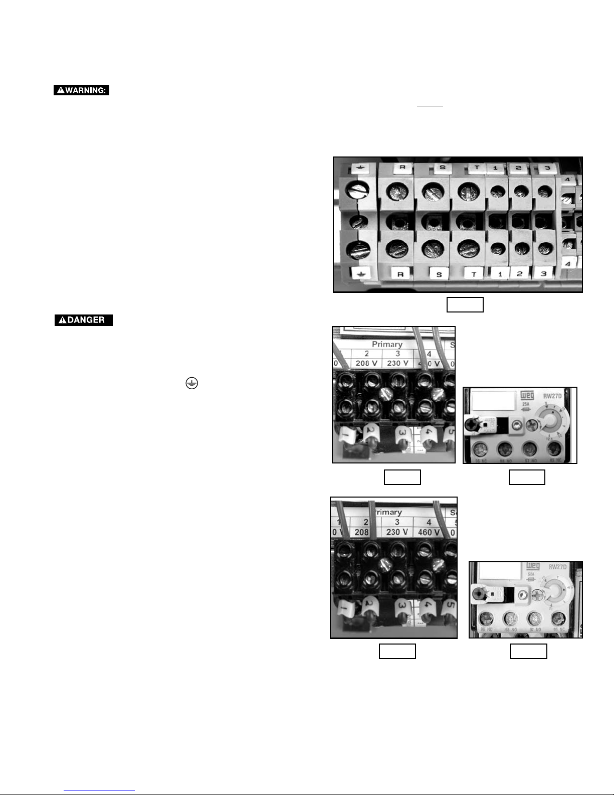
NOTES FOR THE ELECTRICIAN
Use a three-conductor hard-service or junior hard-service
minimum #10 AWG flexible cord with ground to connect the
machine to a protected branch circuit suitable for a 7.5HP,
208-230/460 V three-phase induction motor. The motor
is pre-wired for operation with 208-230 V, 60Hz power.
Connect L1, L2 and L3 to the terminal blocks marked R, S
and T (Fig. A1) and the earthing conductor to the terminal.
Torque the terminal block screws to 4.5-7.0 lb.in. Jog the
power switch and check for proper blade rotation (curvature
of blade should spin towards front of tool). Interchange any
two line leads to reverse.
GROUNDING INSTRUCTIONS
This machine must be grounded while in
use to protect the operator from electric shock.
This tool should be connected to a grounded metal
permanent wiring system; or to a system having an
equipment-grounding conductor. Terminate the connecting
cord earthing conductor in the
of the terminal block. Make certain the other end is securely
bonded to the branch circuit ground.
(earth or ground) terminal
Fig. A1
460 VOLT OPERATION
This unit may be configured to operate from a 460V, 60Hz
source.
(A) Reconnect the motor for 460 V according to motor
nameplate wiring diagram.
B) Change the transformer primary voltage tap from
Terminal 3 (230 V) to Terminal 4 (460 V) (Fig. A2).
(C) Replace the 15-23 A overload with 8-12 A overload set
to 9A trip (Fig. A3).
Torque the overload and contactor terminal screws to 14.2 -
26.6 lb.in. Set the overload to ‘auto’ reset.
208 VOLT OPERATION
The unit is usable from 208 V, 60Hz supply provided
the overload trip current (Fig. A5) is set to 20 A and the
transformer primary voltage tap is changed from terminal ‘3’
to terminal ‘2’ (208 V) (Fig. A4).
Fig. A2
Fig. A4 Fig. A5
Fig. A3
5
Page 6
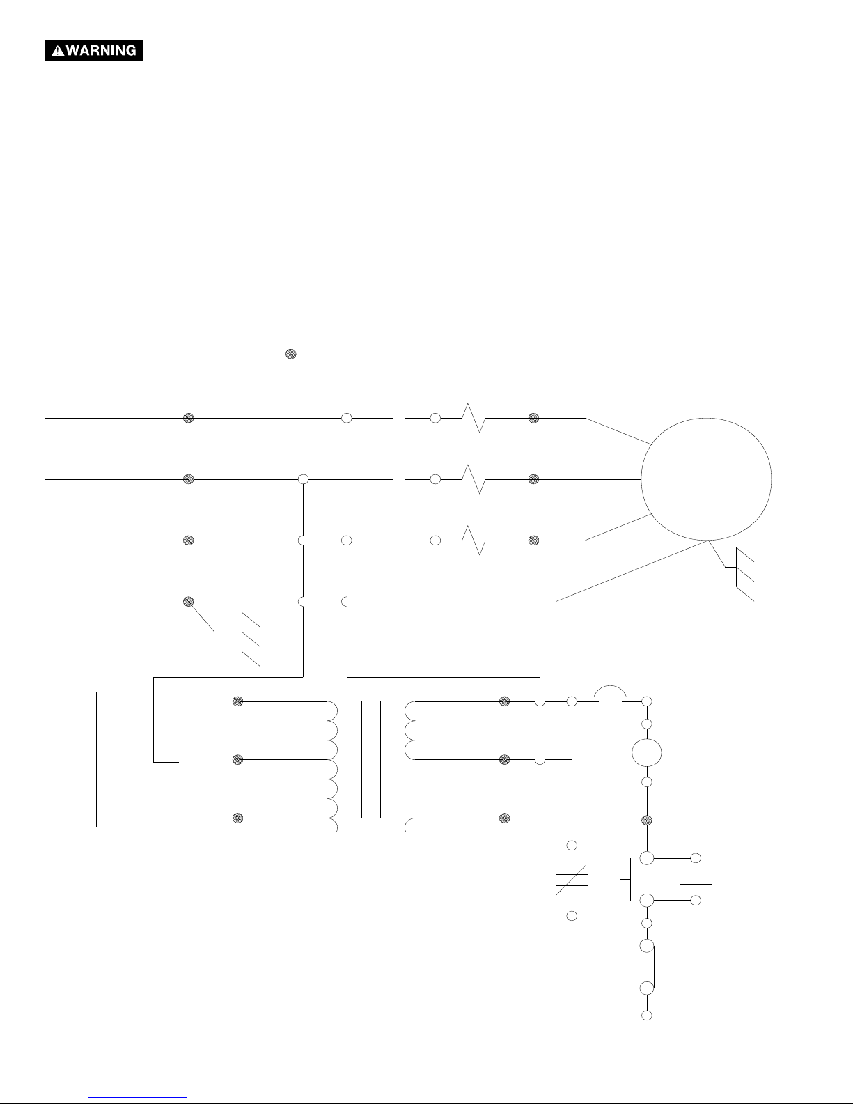
To reduce the risk of serious injury, electrocution, or property damage do not attempt to make
C
1
COM
5
COM
6
24V
4
3
2
460V
230V
208V
Connect as per line
voltage
N
R
S
T
M
2T
1
4T
2
6T
3
4N
O
3N
O
A2
A1
T1
T2
T3
4
5
6
95
NC
96
NC
1L
1
3L
2
5L
3
Connection made by
user
TR
OL
OL
CB
b0
b1
COMPONENTS
b 0
Off Switch
b 1
On Switch
C
Contactor
CB
Circuit Breaker
M
Motor
OL
Overload
Terminal Block
C
C
TR Transformer
any electrical connections on this machine. This diagram is provided only for use by a qualified electrician.
6
Page 7
FUNCTIONAL DESCRIPTION
FOREWORD
The Delta Industrial Model 36-790 14" Tilting Arbor Saw includes a magnetic starter with Low-Voltage Control (LVC)
and automatic reset thermal overload, Biesemeyer® Commercial Fence System, guide bar, miter gage, 43" x 59" table
with two extension wings and fence support extension. A 16” blade can also be used to increase the capacity of the
cut. The maximum depth of cut with 14" blade is 4-1/2" (114 mm) and with a 16" blade it is 5-1/2" (140 mm). At a 45°
angle, the maximum thickness of cut with a 14" blade is 3-1/8" (79 mm) and is 4-1/8" (105 mm) with a 16" bade.
NOTICE: The photo on the manual cover illustrates the current production model. All other illustrations contained in
the manual are representative only and may not depict the actual labeling or accessories included. These are intended
to illustrate technique only.
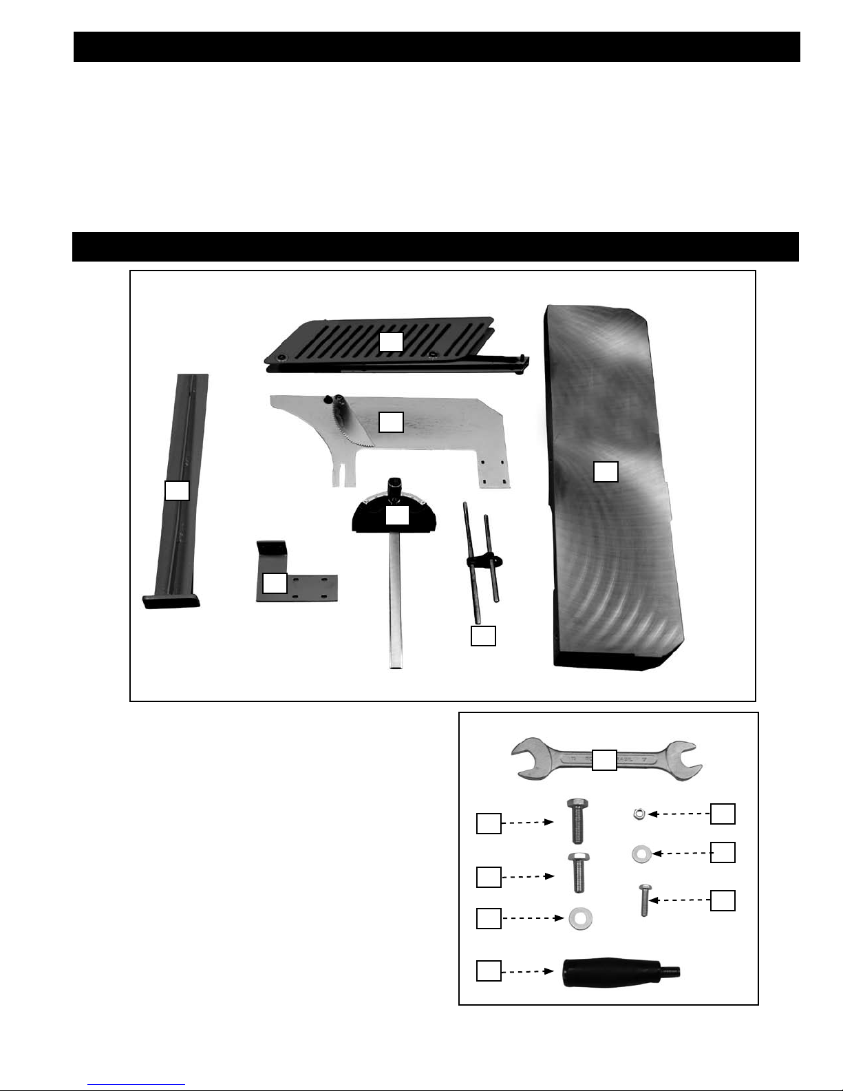
CARTON CONTENTS
2
4
1
5
1. Rip Fence Support Bracket
2. Blade Guard
3. Table Extension Wings
4. Splitter
5. Splitter Mounting Bracket
6. Miter Gauge
7. Stop Rod Assembly
8. 17mm & 19mm Open-End Wrench
9. M10 x 35mm Hex-Head Bolt
10. M6 Nut
11. M8 x 25mm Hex Head Bolt
12. 8mm Flat Washers
13. M10 Flat Washers
14. M6 x 20mm Hex-Head Bolts
15. Handle
3
6
7
8
9
10
12
11
14
13
15
7
Page 8
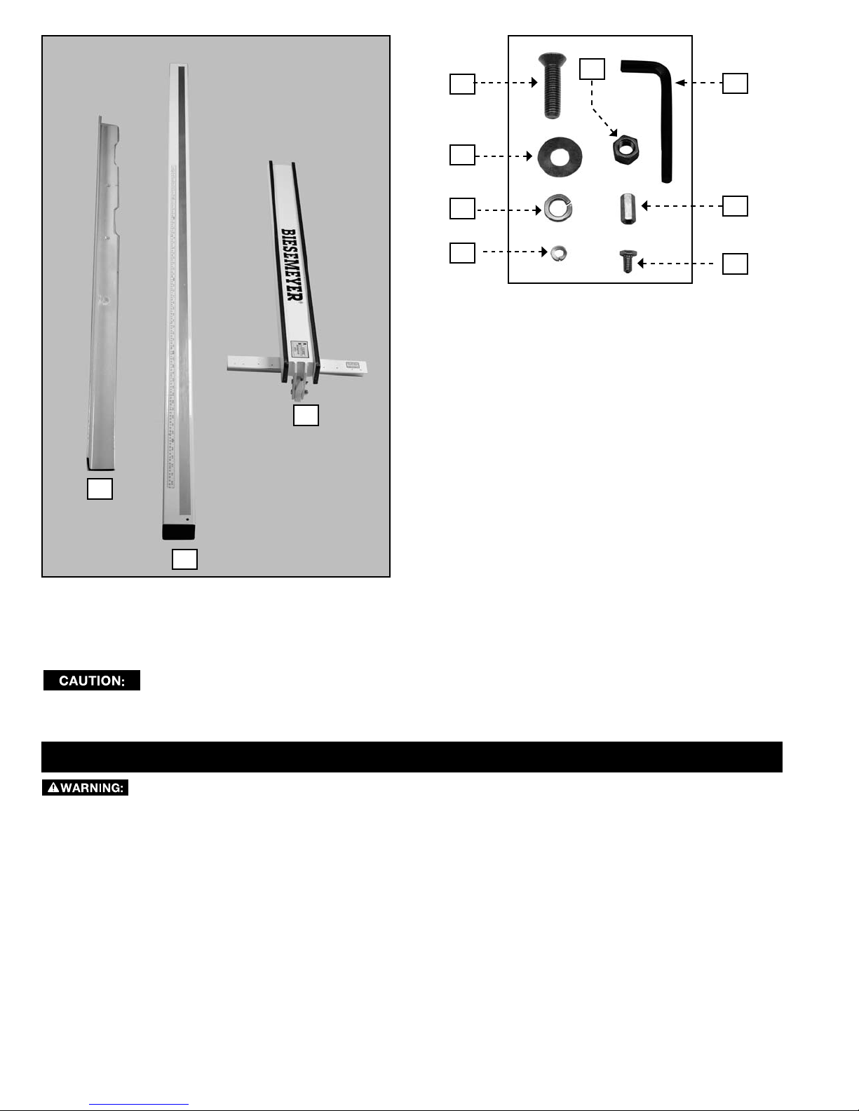
7
4
5
6
8
10
1. Front Rail
2. Guide Tube
3. Fence Assembly
4. 1/2"-13 x 2" Flat Head Bolts
5. 5/16" Hex Wrench
6. 1/2" Flat Washer
3
1
7. 1/2"-13 Hex Nuts
8. Lockwasher
9. Retaining Nut
10. Lockwasher
11. Retaining Nut Bolt
9
11
2
UNPACKING AND CLEANING
Carefully unpack the machine and all loose items from the shipping container(s). Remove the rust-preventative oil from
unpainted surfaces using a soft cloth moistened with mineral spirits, paint thinner or denatured alcohol.
Do not use highly volatile solvents such as gasoline, naphtha, acetone or lacquer thinner for cleaning your
machine.
After cleaning, cover the unpainted surfaces with a good quality household floor paste wax.
ASSEMBLY
To reduce the risk of injury, turn unit off and disconnect it from power source before installing and remov-
ing accessories, before adjusting or when making repairs. An accidental start-up can cause injury.
ASSEMBLY TOOLS REQUIRED
* 17mm and 19mm open end wrench (supplied)
* Blade wrench (supplied)
ASSEMBLY TIME ESTIMATE
Assembly for this machine takes approximately 2-3 hours.
8
Page 9
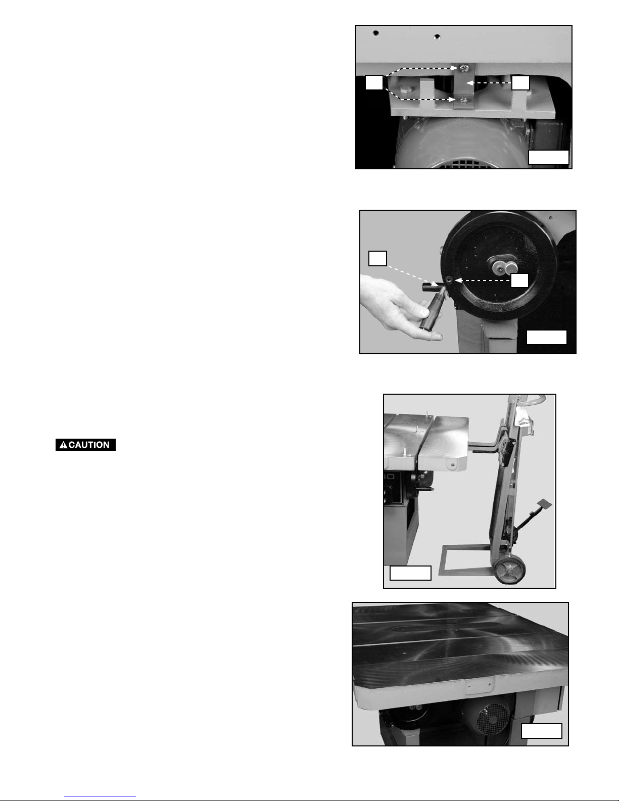
IMPORTANT - Before assembling this machine, remove
the two bolts (A) Fig. 1 and the red shipping strap (B).
This bracket protects the motor during shipment.
A
HOW TO ATTACH THE HANDLE TO THE ELEVATOR MECHANISM
B
Fig. 1
Insert the threaded end of the handle (A) Fig. 2 in the
threaded hole of the elevator wheel (B) and tighten it
securely by turning it clockwise.
HOW TO ATTACH THE TABLE EXTENSION WINGS
The table extension wings are very heavy.
Use a lifting device (Fig. 3) to lift and hold the extension
table in place during installation.
A
B
Fig. 2
This machine is supplied with two table extension wings.
Attach the extension wing with the two tapped holes (A)
Fig. 4 to the right side of the machine.
Fig. 3
Fig. 4
9
Page 10
A
B
C
A
Fig. 5
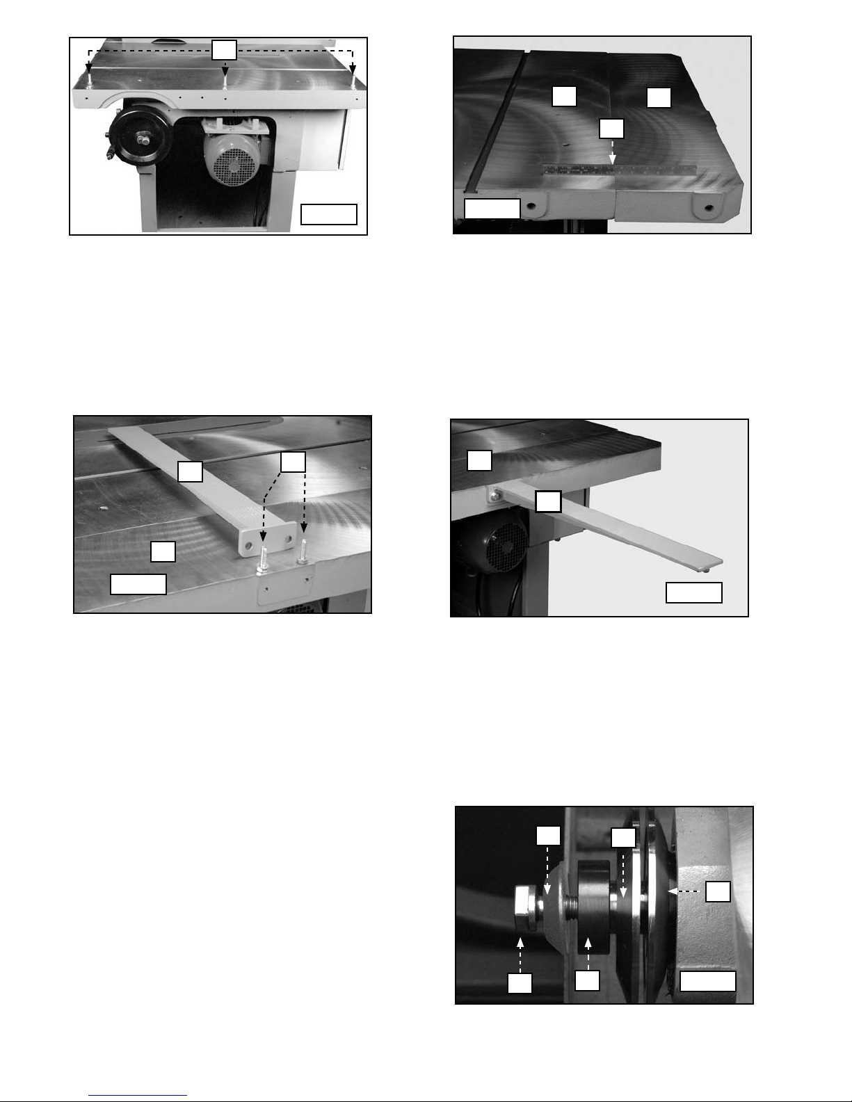
Attach the extension wing to the saw with three M10 x 35mm hex-head bolts (A) Fig. 5.
Note: Loosely tighten the bolts for further adjustment.
Place a straight-edge (A) Fig. 6 on the saw (B) and the extension table (C) over the first bolt to check the level. When
the two are level, tighten the bolt. Do the same with the far bolt. Tighten all hardware securely.
Install the other extension wing in the same manner.
Fig. 6
HOW TO ATTACH THE RIP FENCE SUPPORT BRACKET
A
C
B
A
A
B
Fig. 7
Attach the rip fence support bracket (A) Fig. 7 to the saw (B) with two M8 x 35mm hex-head bolts (C) Fig. 7.
Note: Loosely tighten the bolts for further adjustment.
Place a straight-edge on the saw (B) and the fence support bracket (A) to check the level. When the two are level,
tighten the bolts. Tighten all hardware securely.
Fig. 8
HOW TO ATTACH A SAW BLADE
NOTE: No blade is supplied with this saw.
1, Remove the table insert and raise the saw arbor to its
full height by turning the elevation handwheel.
NOTE: Turn the arbor bolt clockwise to loosen.
2. Use the provided blade wrench to remove the arbor
bolt (A), the retainer (B), the spacer (C), and the blade
flange (D).
B
D
E
NOTE: Leave the inside blade flange (E) on the arbor.
NOTE: Press the lock button (A) Fig. 11 to prevent the
arbor from rotating.
10
A
C
Fig. 9
Page 11
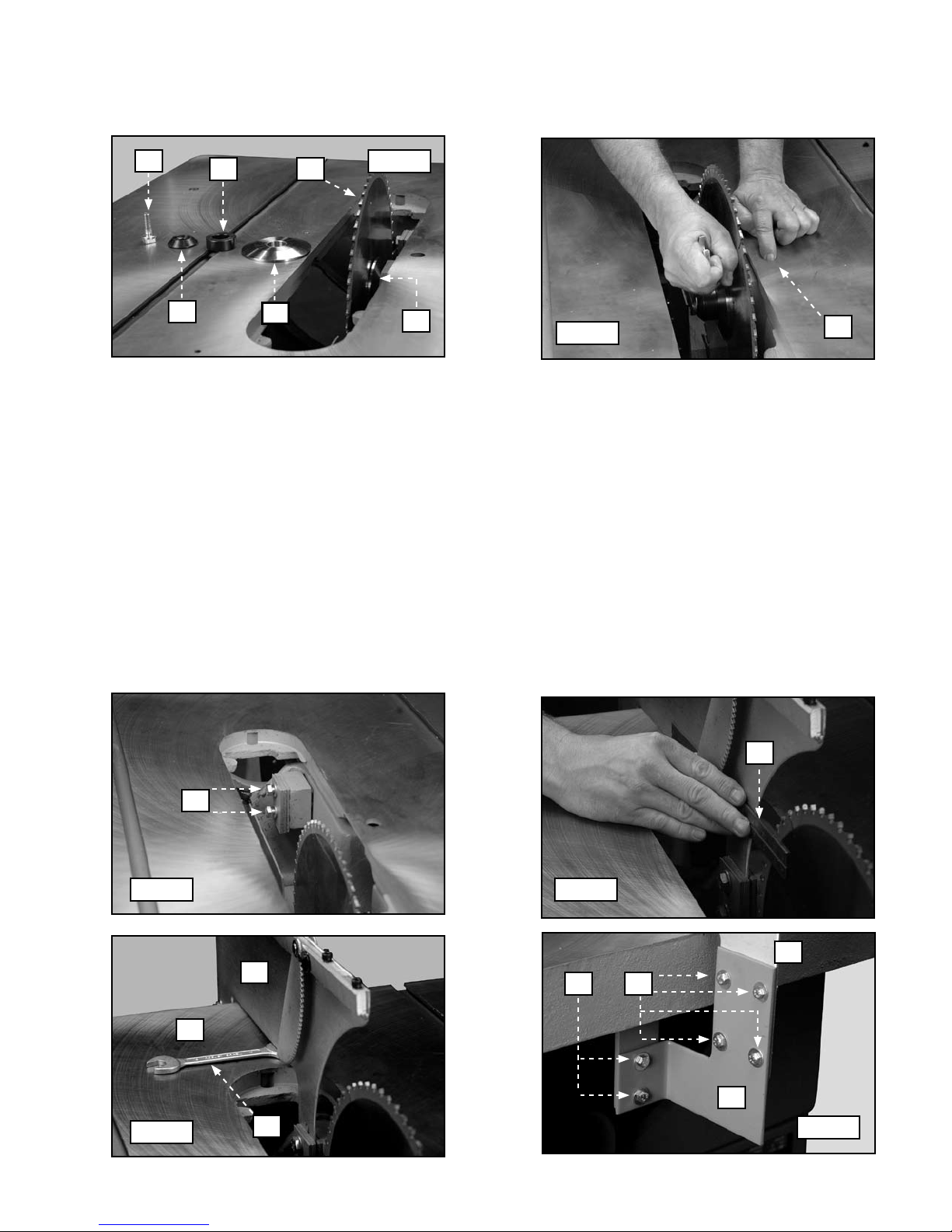
3. Place the saw blade (A) Fig. 10 with the teeth pointing down toward the front of the saw, against the interior blade
C
flange (B).
4. Add the exterior blade flange (C ), the spacer (D ), the retainer (E ), and the arbor bolt (F).
5. Press down on the arbor lock button (A) Fig. 11 and securely tighten the arbor bolt by turning it counter-clockwise.
F
D
A
E
Fig. 10
B
Fig. 11
A
HOW TO ATTACH THE BLADE GUARD AND SPLITTER ASSEMBLY
IMPORTANT: The width of the blade determines the correct position of the splitter on the splitter mounting bracket.
1. Loosen the two bolts (A) Fig. 12.
NOTE: Three sizes of individual spacers are located on the splitter mounting bracket.
2. Place a straight edge (A) Fig. 13 against the back of the blade. Align the blade with the splitter.
3. Place the splitter where indicated inside the spacers of the splitter mounting bracket.
NOTE: Position the splitter approximately 1/8" above the table surface.
4. Use the arbor wrench (A) Fig. 14 as a spacer. Place it between the splitter (B) and the table surface (C). Tighten the
two bolts (A) Fig. 12.
5. Use the four M6 x 20mm hex-head screws (A) Fig. 15, the eight flat washers, and four hex nuts to attach the splitter
bracket (C) Fig. 15 to the splitter (D).
6. Use the two M6 x 25mm hex-head bolts (B) Fig. 15, four flat washers, and two hex nuts to attach the splitter bracket
assembly to the clamp.
NOTE: Loosely tighten the bolts for further adjustment.
A
Fig. 12 Fig. 13
B
C
Fig. 14
A
11
A
D
AB
C
Fig. 15
Page 12

6. Lower the blade and attach the table insert (A) Fig.
16 to the saw table. Use a straight edge (B) to see if
the table insert (A) is level with the table surface (C).
Level the table insert by turning the necessary hex
bolts at (D).
B
D
A
7. Use the arbor wrench as a spacer to adjust the
height of the anti-kickback finger (A) Fig. 17. Place
the wrench under the anti-kickback finger, loosen the
screw (B) and adjust the cam (C) so that the antikickback finger (A) is pointing to the rear and not
touching the table. Adjust the other kickback finger
in the same manner.
IMPORTANT: Rotate the blade-beveling handle until
the blade is at the 45° bevel position. Check the anti-
kickback finger to see that it is not touching the table.
B
D
C
Fig. 16
C
A
Fig. 17
8. Use a straight-edge (A) Fig. 18 to see if the splitter
(B) is aligned with the blade (C). Tighten the mounting
bolts.
9. Remove the two bolts (A) Fig. 19 from the top of the
splitter (B) Attach the guard basket assembly Fig. 20
to the splitter with the two bolts.
B
A
Fig. 19
A
Fig. 18
B
C
Fig. 20
12
Page 13
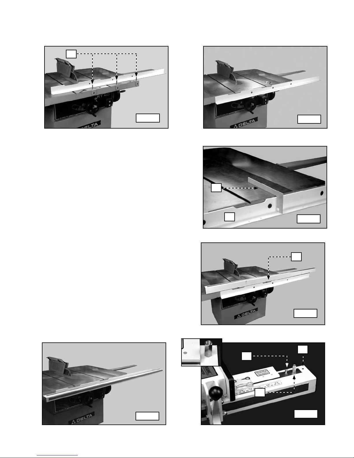
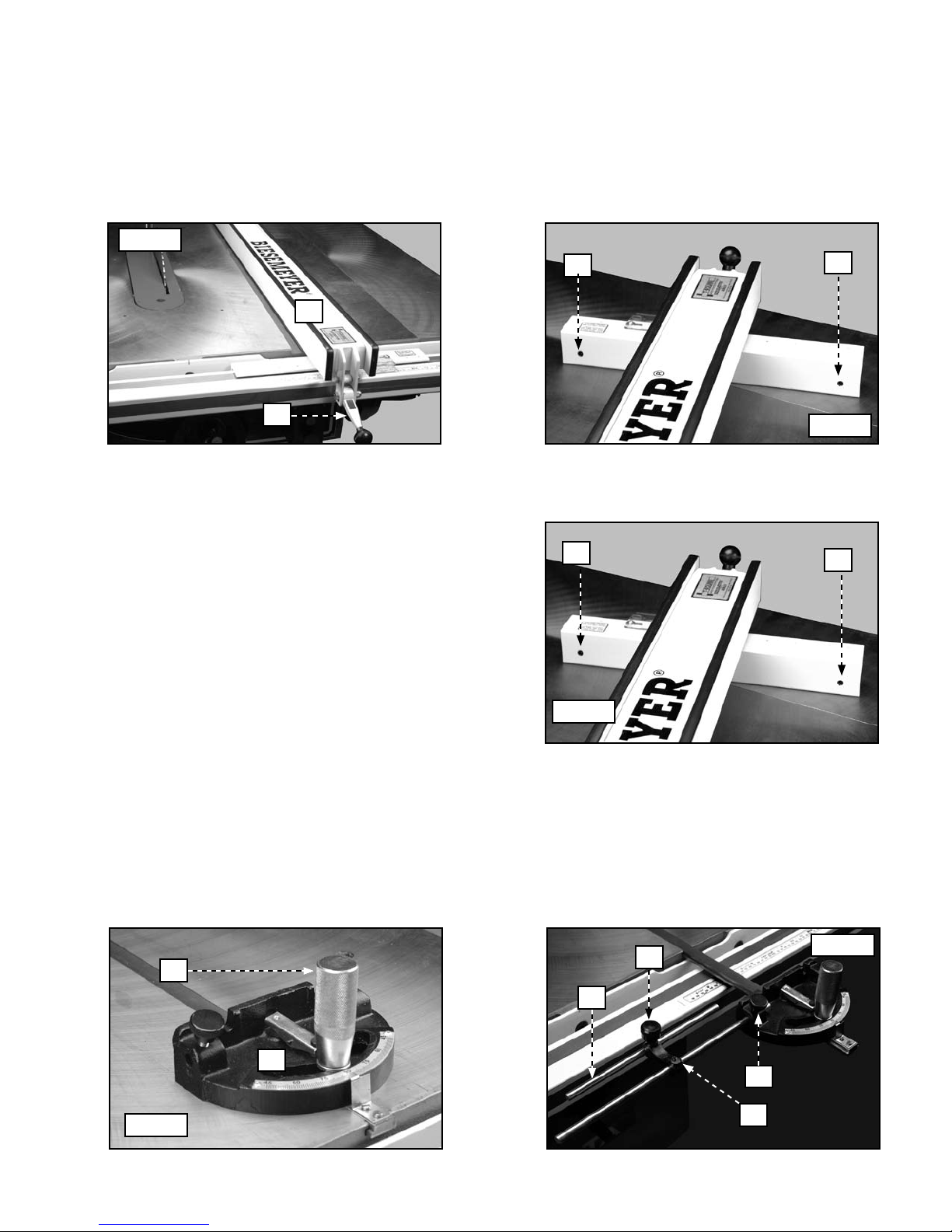
HOW TO ATTACH THE RIP FENCE GUIDE RAIL
1. Use three (3) 1/2-13 X 2" flat-head bolts, flat washers, lockwashers, and hex nuts (A) Fig. 21 to attach the guide rail
to the front of the saw table (Fig. 22). Loosely tighten with the supplied hex wrench for further adjustment.
A
Fig. 21
2. Use the template (A) Fig. 23 that is supplied with the
fence system to check and adjust the level of the
front rail (B) to both ends of the saw table. Tighten
the guide rail hardware securely.
NOTE: Do NOT level the rail with the extension wing. Use
the saw table.
3. Place the guide tube (A) Fig. 24 on the saw table.
Align the nine (9) threaded holes with the holes in the
front ledge.
4. Position the guide tube on the front rail. Secure the
guide tube with nine (9) 1/2" hex-head bolts and
lockwashers.
5. Place the rip fence on the guide rail.
6. Insert a bolt (A ) Fig. 26 up through the hole (B ) at
the extreme right end of the guide tube. Thread the
retaining nut (C ) on the bolt (see the inset - Fig. 26)
NOTE: This retaining nut prevents the fence from falling
off the end of the guide rail.
A
B
Fig. 22
Fig. 23
A
IMPORTANT: Before applying power to the saw, en-
sure that the rip fence is parallel to the miter gauge
slot. Refer to the section "HOW TO OPERATE AND
ADJUST THE RIP FENCE".
Fig. 25
Fig. 24
B
A
C
Fig. 26
13
Page 14
HOW TO ATTACH THE MITER GAUGE AND STOP-ROD ASSEMBLY
1. Insert the miter gauge bar (A) Fig. 27 in the T-Slot of the saw table. The t-slot miter gauge bar will prevent the miter
gauge from falling when it is extended beyond the table surface.
2. Loosen the lock knob (A) Fig. 28 and insert the end of the stop rod (D) in the hole on the side of the miter gauge
body.
3. Tighten the lock knob (A) Fig. 28.
A
A
D
Fig. 27
Fig. 28
OPERATION
OPERATIONAL CONTROLS AND ADJUSTMENTS
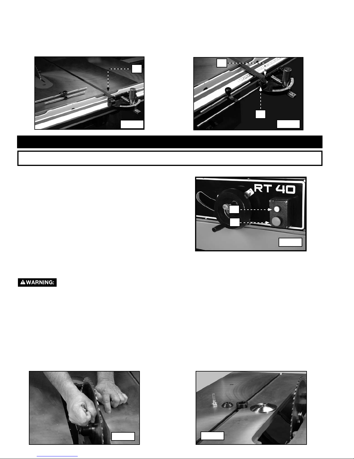
HOW TO START AND STOP THE MACHINE
The start/stop switch is located at the front of the machine.
To start the machine, push the green button (A). To stop the
machine, push the large red button (B).
OVERLOAD PROTECTION
This machine will shut the motor down because of overloading
or low voltage.
If the machine shuts down, let it cool for about five minutes,
then push the green start button.
IMPORTANT: If the saw shuts off frequently, have a qualified
electrician find the problem and correct it.
A
B
Fig. 29
HOW TO CHANGE THE BLADE
Shut off the power source to the machine.
1. Remove the blade guard and the table insert.
NOTE: Remove the splitter assembly ONLY if the thickness of the replacement blade is different from the original blade.
2. Raise the blade to its fullest height.
3. Push the arbor lock button down and use the provided arbor wrench to remove the arbor bolt. Turn the wrench
toward the front of the saw.
4. Position the new blade on the saw arbor. Replace the blade flange, the space, the retainer, and the arbor bolt.
5. Push the arbor lock button down, and tighten the blade assembly by turning the wrench toward the rear of the
saw.
6. Replace the table insert and the blade guard. If you removed the splitter assembly, replace it.
NOTE: If the new blade is of a different thickness from the old blade, refer to "HOW TO ATTACH THE BLADE GUARD
AND SPLITTER ASSEMBLY" for proper placement of the splitter.
Fig. 30
Fig. 31
14
Page 15
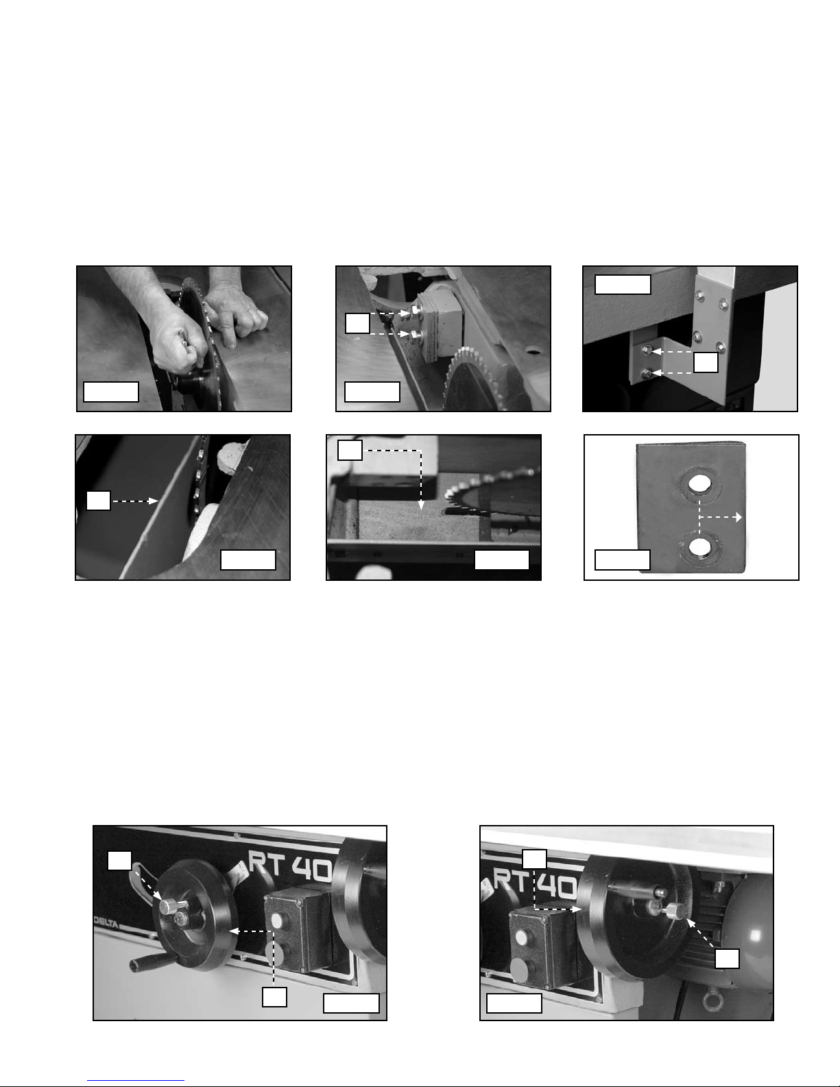
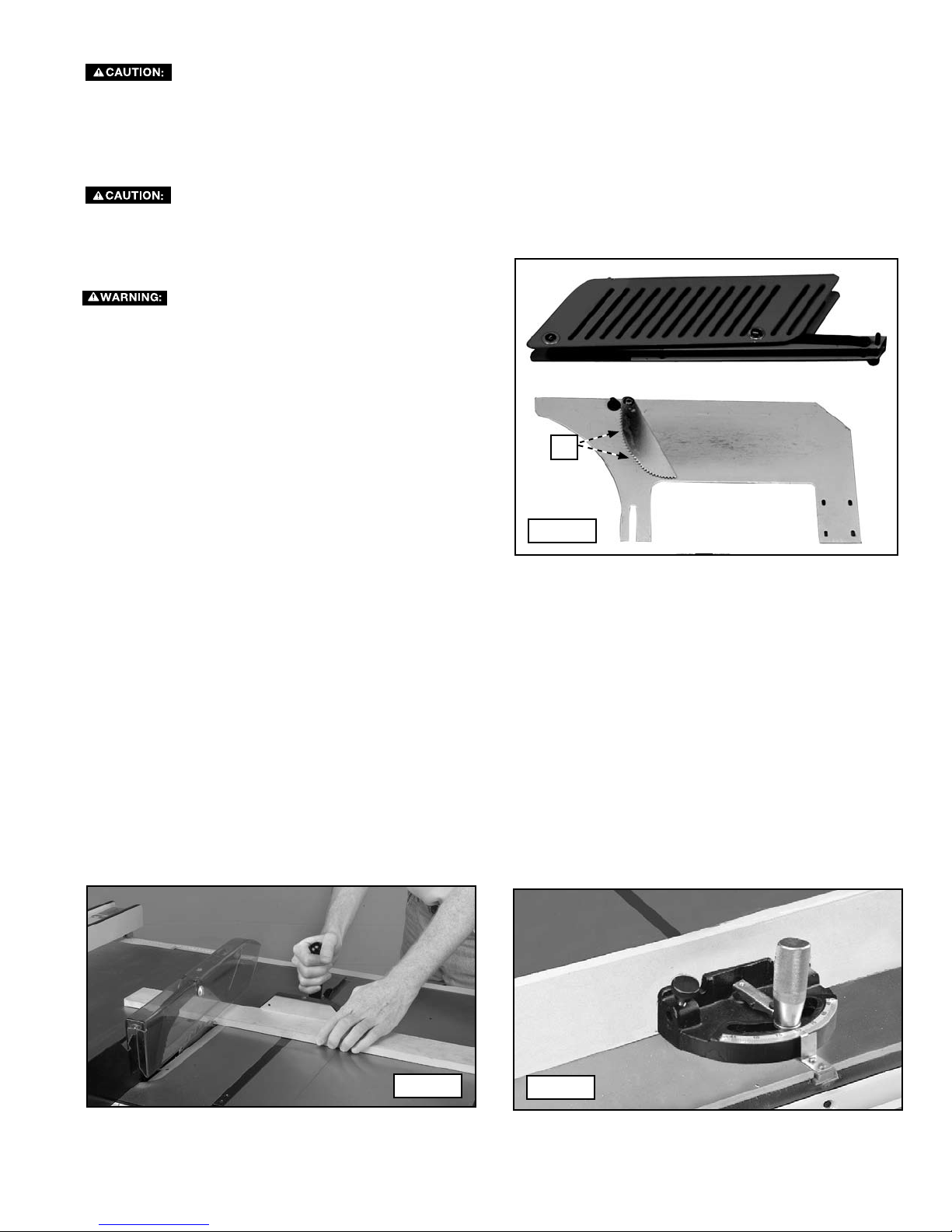
HOW TO ATTACH A 16" BLADE
1. Remove the blade guard and the table insert.
2. Raise the blade to its fullest height.
3. Push the arbor lock button down and use the provided arbor wrench to remove the arbor bolt. Turn the wrench
toward the front of the saw.
4. Remove the plates (A) Fig. 33.
5. Remove the two bolts (A) Fig. 34 and take off the splitter bracket.
6. Remove the guard (A) Fig. 35 and wooden block (A) Fig. 36.
7. Position the new blade on the saw arbor. Replace the blade flange, the space, the retainer, and the arbor bolt.
8. Replace the guard and block.
9. Replace the plates with the short area toward the blade (Fig. 37). The holes in the plate are cut off center.
10. Push the arbor lock button down, and tighten the blade assembly by turning the wrench toward the rear of the
saw.
11. Replace the table insert and the splitter assembly.
Fig. 34
A
A
Fig.32 Fig. 33
A
A
Fig. 35
Fig. 36 Fig. 37
HOW TO RAISE AND LOWER THE BLADE
To raise the blade, loosen the locking knob (A) Fig. 38 and rotate the handwheel (B) clockwise.
To lower the blade, loosen the locking knob and rotate the handwheel counter-clockwise.
Lock the blade at any height with the locking knob (A) Fig. 38.
IMPORTANT: Lock the blade before applying power to the saw.
HOW TO TILT THE BLADE
Loosen the locking knob (A) Fig. 39 and rotate the handwheel (B) clockwise.
Lock the blade at any angle with the locking knob (A) Fig. 37.
IMPORTANT: Lock the blade before applying power to the saw.
Short
area
A
B
B
A
Fig. 38 Fig. 39
15
Page 16
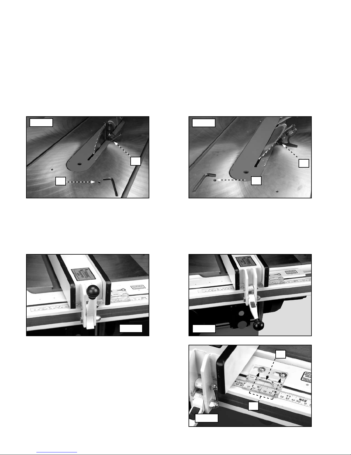
HOW TO ADJUST THE POSITIVE STOPS
This machine has positive stops that will allow you to quickly and accurately position the blade at 90° and 45° to the
table. To check and adjust the positive stops:
1. Raise the blade to its fullest height.
2. Position a square (A) Fig. 40 against the blade and the table to check the angle.
3. If the blade is not 90° to the table, remove the lock screw located inside the hole (B) and slightly loosen the adjustment screw located underneath the lock screw. Rotate the tilting handwheel until the blade is at the correct angle.
Tighten the adjustment screw until it bottoms. Replace the lock screw. Check the angle of tilt indicator on the handwheel is pointing to "0". If not, adjust it.
4. Tilt the blade as far as it will go by turning the tilting handwheel counter-clockwise.
5. Position a square (A) Fig. 41 against the blade and the table to check the angle.
6. If the blade is not 45° to the table, remove the lock screw located inside the hole (C) and slightly loosen the adjustment screw located underneath the lock screw. Rotate the tilting handwheel until the blade is 45° to the table. Tighten
the adjustment screw until it bottoms. Replace the lock screw.
Fig. 40
Fig. 41
A
B
HOW TO OPERATE AND ADJUST THE RIP FENCE
To move the fence along the guide rail, lift the clamp lever (Fig. 42).
To lock the fence in position, push down on the clamp lever (Fig. 43).
NOTE: The clamp lever will remain in the "up" position when you move the fence.
A
C
Fig. 42
The distance the fence is positioned from the blade is
indicated by the witness line (A) Fig. 44 on the cursor.
To adjust the cursor, test cut a workpiece with the fence
locked in position. Measure the width of the workpiece.
Loosen the two screws (B), adjust the cursor until the
witness line (B) is aligned with the previous measurement. Tighten the screws.
Fig. 43
A
B
Fig. 44
16
Page 17
HOW TO ADJUST THE FENCE PARALLEL TO THE MITER GAUGE SLOTS
IMPORTANT: Be certain that the miter gauge slots are parallel with the blade before adjusting the fence.
Move the fence (A) Fig. 45 until the bottom edge is aligned with the edge of one of the miter gauge slots and lock it in
place with the lock clamp (B). If the fence is not parallel to the slot, raise the lock clamp, and lift the fence off of the
guide tube. Use a 3/16" hex wrench (not supplied) to tighten or loosen the adjustment screw (either C or D) Fig. 46 that
applies.
IMPORTANT: Any necessary adjustments should be very small.
Fig. 45
C
D
A
B
Fig. 46
HOW TO ADJUST THE CLAMP HANDLE
When the clamp handle is in the "down" position (Fig.
47), the fence will lock to the guide tube. If this is not the
case, lift the clamp handle and raise the fence assembly
off of the guide tube. Slightly tighten the two adjusting
screws (D) and (E) an equal amount, using a 3/16" hex
wrench. Replace the fence assembly and check for correct clamping. Repeat as necessary.
IMPORTANT: After adjustment of the clamp handle, recheck to see that the fence and miter gauge slots are
parallel.
E
Fig. 47
F
HOW TO ADJUST THE MITER GAUGE AND STOP RODS
You can adjust the miter gauge (A) Fig. 48 right and left by loosening the locking handle (B), pushing down on lever, and
rotating the miter gauge body. Lock the body in position with the locking handle (B)
You can adjust the stop rods (D) Fig. 49 by loosening the set screw (E) or loosening the knob (F). The stop rods can be
removed by loosening the knob (G).
B
A
Fig. 48
17
D
F
Fig. 49
G
E
Page 18
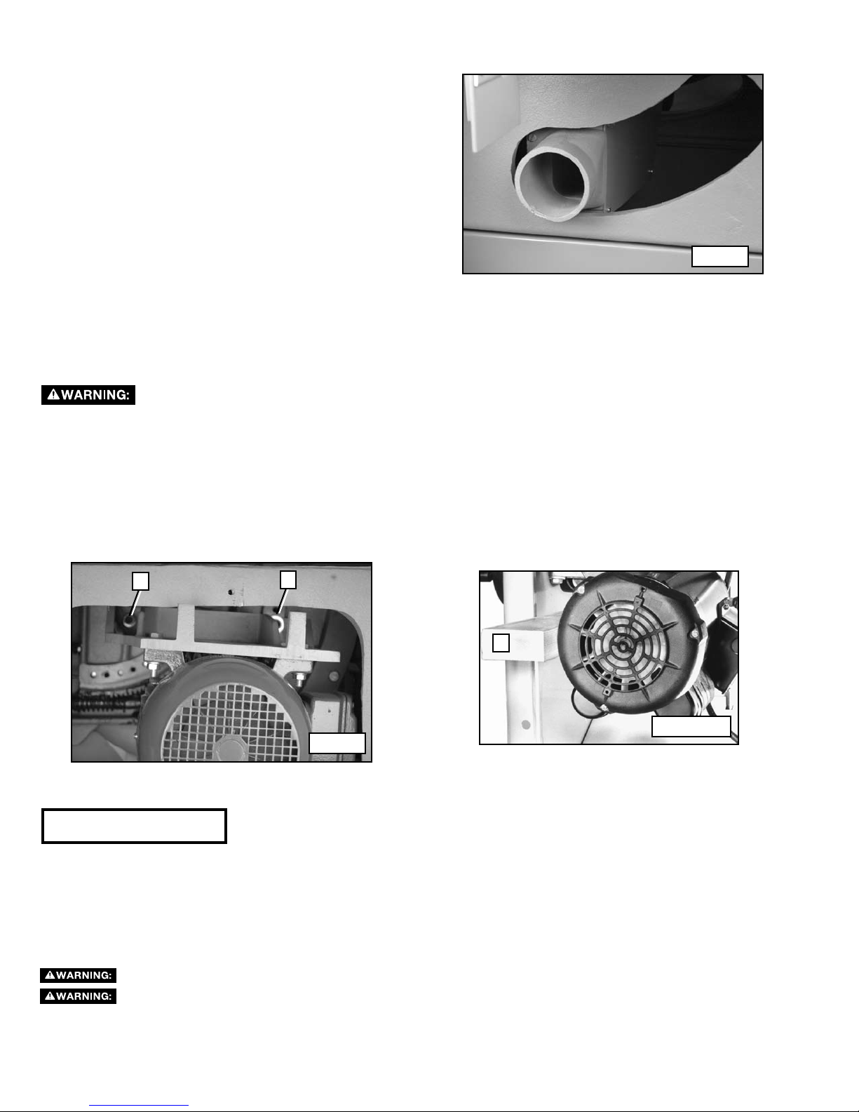
DUST CHUTE
This machine is equipped with a 3-1/2" O.D. dust chute (Fig.
50) that easily adapts to a central dust collection system.
Fig. 50
HOW TO CHANGE SPEEDS AND ADJUST BELT TENSION
This saw has a double V-belt drive that provides blade speeds of 3000 and 4500 RPM. To achieve the faster speeds, place the
belts on the largest steps of the motor pulley and the smallest steps of the arbor pulley.
Shut off the power source to the machine.
1. Position the blade in the 90° position and lower the blade about two turns.
2. Loosen the bolt (A) Fig. 51 and remove the bolt (B).
3. Place a block of wood (C) Fig. 51A between the motor and the inside of the saw cabinet. Lower the motor against
the block of wood until the belt tension is released.
4. Position the belts on the motor and spindle pulleys and raise the blade. The weight of the motor is sufficient to
provide proper tension.
5. Tighten the bolt (A). Replace and tighten the bolt (B).
A
B
C
Fig. 51A
Fig. 51
MACHINE USE
Common sawing operations include ripping and cross cutting plus a few other standard operations. As with all power machines,
a certain amount of hazard is involved with the operation and use of the machine. Using the machine with the respect and
caution will considerably lessen the possibility of personal injury. However, if normal safety precautions are overlooked or
completely ignored, personal injury can result. The following information describes the safe and proper method for performing
the most common sawing operations.
The use of attachments and accessories not recommended be Delta may result in injury.
Never operate the saw without the proper table insert for the saw blade or cutter installed.
18
Page 19
QUICK OPERATIONS CHECKLIST
Before using the saw each time, verify the following:
1, The blade is tight.
2. The bevel angle and height lock-knobs are tight.
3. If ripping, ensure that the fence lock lever is tight and that the fence is parallel to the blade.
4. If crosscutting, ensure that the miter gauge knob is tight.
5. Proper eye, hearing, and respiratory equipment are being used.
6. The blade guard is properly attached and the anti-kickback pawls are functioning.
Failure to adhere to these common safety rules can greatly increase the likelihood of injury.
BLADE GUARD AND SPLITTER USE
The blade guard assembly provided with
Delta saws (Fig. 52) must be used for all through-sawing
operations. The splitter prevents the kerf from closing and
binding the blade, causing kickback. The anti-kickback pawls
(A) Fig. 52 prevent the workpiece and the cut-off piece from
being thrown back at the operator. The guard prevents dust
and debris from being thrown at the operator. To use the guard
properly:
1. Make sure that the splitter is aligned with the blade
as described in the section “BLADE GUARD AND
SPLITTER ASSEMBLY AND ALIGNMENT.”
2. Replace or sharpen the anti-kickback pawls when they
become dull.
3. Keep the guard clean.
4. Use caution when feeding workpieces that may catch
on the guard and cause a bind, or force the guard into
the blade (such as when cutting moulding).
A
Fig. 52
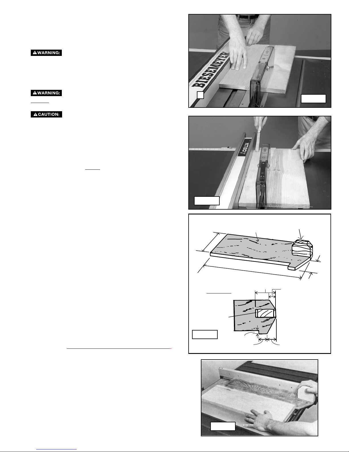
CROSS-CUTTING
Cross-cutting requires the use of the miter gauge to posi tion and guide the work. Before starting the cut, raise the blade so that
it is about 1/8” (3.2mm) higher than the top of the workpiece. Place the work against the miter gauge and advance both the
gauge and work toward the saw blade (Fig. 53). You can use the miter gauge in either table slot. Start the cut slowly and hold
the work firmly against the miter gauge and the table. Keep both hands on the miter gauge and workpiece. Do not touch the
cut-off piece. Feed the workpiece steadily through the blade until the workpiece is completely cut. Shift the workpiece slightly
sideways away from the blade, then pull the workpiece and miter gauge back to the starting position. Remove the workpiece,
then use a push stick to push the cut-off piece past the blade and off the table before beginning the next cut.
For added safety and convenience, you can attach an auxiliary wood-facing (C) Fig. 54 to the miter gauge. This facing should
be at least 1" higher than the maximum depth of cut, and should extend out 12" or more to one side or the other depending
on which miter gauge slot is used. Attach this auxiliary wood-facing (C) to the front of the miter gauge by using two wood
screws with a washer through the slots provided in the miter gauge body.
Fig. 53
Fig. 54
19
Page 20
Never use the fence as a cut-off gauge when cross-cutting.
When cross-cutting a number of pieces to the same length,
clamp a block of wood (B) to the fence and use it as a cutoff gauge (Fig. 55). The block (B) must be at least 3/4" thick
to prevent the cut-off piece from binding between the blade
and the fence during removal from the saw table. Always
position this block of wood in front of the saw blade. Once
the cut-off length is determined, lock the fence and use the
miter gauge to feed the work into the cut.
When using the block (B) Fig. 55 as a cut-
off gauge, position the rear end of the block so that the
workpiece is clear of the block before it enters the blade.
Fig. 55
B
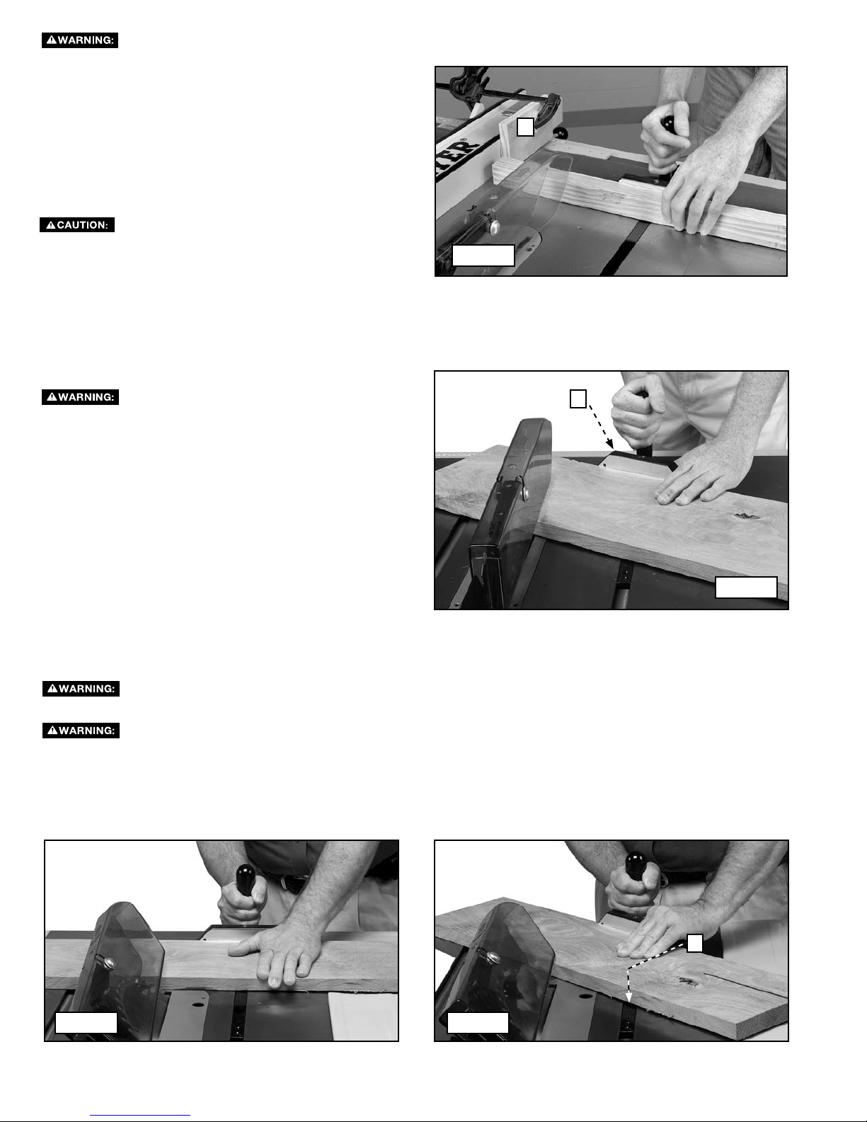
MITERING
Mitering (Fig. 56) is the same as crosscutting except the miter gauge (C) is locked at an angle other than 0°. Hold the workpiece
firmly against the miter gauge and feed the work slowly into the blade to prevent the workpiece from moving.
Use caution when starting the cut to prevent
binding of the guard against the workpiece. Miter angles
greater than 45° may force the guard into the saw blade
and damage the guard. Before starting the motor, test
the operation by feeding the workpiece into the guard. If
the guard contacts the blade, place the workpiece under
the guard, not touching the blade, before starting the
motor. Certain workpiece shapes, such as mouldings,
may not lift the guard properly. Feed the work slowly to
start the cut.
C
Fig. 56
BEVEL CROSSCUTTING
Bevel crosscutting (Fig. 57) is the same as crosscutting except the bevel angle is set to an angle other than 0°.
When possible, use the right miter gauge slot when bevel crosscutting so that the blade tilts away from
the miter gauge and your hands.
Use caution when starting the cut to prevent binding of the guard against the workpiece.
COMPOUND MITERING
Compound Mitering (Fig. 58) is a combination of bevel crosscutting and mitering, where the blade is beveled to an angle other than
0° and the miter gauge is locked at an angle other than 0 degrees. Always use the miter slot (D) which allows the blade to tilt away
from the miter gauge and hands.
Fig. 57 Fig. 58
D
20
Page 21
3/4” plywood
6”
Width of saw + 2”
3-5/8”
2” x 4”
block
TOP VIEW
4”
1”
3/8”
1”
2-1/4”
2” x 4”
block
RIPPING
Ripping (Fig. 59) is cutting lengthwise through a board. The
rip fence (A) is used to position and guide the work. One
edge of the work rides against the rip fence while the flat
side of the board rests on the table.
Delta saws, the guard has anti-kickback pawls to
prevent kickback, and a splitter to prevent the wood
kerf from closing and binding the blade. Be sure to
replace or sharpen the anti-kickback devices when the
points become dull.
NEVER perform a ripping operation free-hand. Always
lock the fence to the rail.
against the fence, and must not be warped, twisted or
bowed.
1. Before starting the cut, raise the blade so that it is about
2. When the workpiece is past the blade, the work
3. If the size or shape of the workpiece would cause your
4. Ripping narrow pieces can be dangerous. If possible, rip
NOTE: In Fig. 62, the guard and splitter have been removed
5. For longer pieces, use one or more pushsticks to avoid
NOTE: Some special operations (moulding cutterhead,
etc.) require the addition of an auxiliary wood facing to the
fence, as explained in the section “USING AUXILIARY
WOOD FACING,” and use of a push stick.
You must use the saw blade guard. On
Always use a rip fence for ripping operations.
The workpiece must have a straight edge
1/8” (3.2mm) higher than the top of the workpiece. Start
the motor and advance the work, holding it down and
against the fence. Never stand in the line of the saw cut
when ripping. When the rip width is 6 inches or wider,
hold the work with both hands and push it along the
fence and into the saw blade (Fig. 59). Feed force when
ripping should always be applied between the saw blade
and the fence. Never pull the workpiece from the back
of the saw. The work should then be fed through the
saw blade with the right hand. Keep pressure on the
workpiece against the fence and down on the saw table.
Ensure that you have adequate outfeed support for the
workpiece and KEEP YOUR HANDS AWAY FROM
THE SAW BLADE.
will either stay on the table or tilt up slightly and be
caught by the end of the guard. Alternately, the feed
will continue to the end of the table, and be lifted and
brought along the outside edge of the fence. When
ripping boards longer than three feet, use a work
support at the rear of the saw to keep the workpiece
from falling off the saw table.
hands to be within six inches of the saw blade, use a
push stick to complete the cut (Fig. 60) The push stick
can easily be made from scrap material as explained in
the section “CONSTRUCTING A PUSH STICK.”
the narrow piece from the larger piece. If the workpiece
is short enough, use a pushboard. (A pushboard can be
constructed as shown in Fig. 61 and used as shown in
Fig. 62.)
for clarity. Use the guard and splitter when ripping.
placing your hands between the fence and the blade.
Always use care to avoid binding narrow strips between
the anti-kickback pawls and the splitter.
A
Fig. 60
Fig. 61
Fig. 59
Fig. 62
21
Page 22
BEVEL RIPPING
Bevel ripping (Fig. 63) is the same as ripping except the
bevel angle is set to an angle other than 0°.
When possible, place the fence on the right
side of the blade so that the blade is tilted away from
the fence and hands. keep your hands clear of the blade
and use a pushstick to feed the workpiece if there is less
than 6” between the fence and the blade.
Use caution when starting the cut to prevent
binding of the guard against the workpiece.
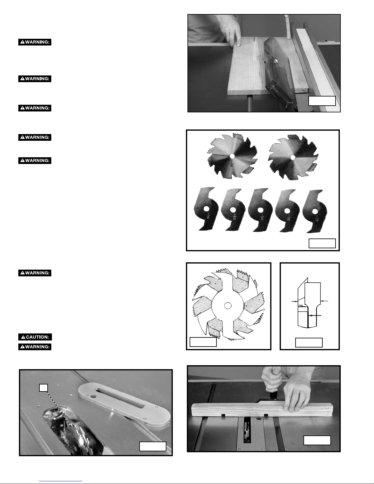
USING AN ACCESSORY DADO HEAD
The blade guard and splitter assembly cannot
be used when dadoing or moulding. It must be removed
as described in “USING AN ACCESSORY MOULDING
CUTTERHEAD” section.
Use pushsticks, hold-downs, jigs, fixtures,
or featherboards to help guide and control the workpiece
when the guard cannot be used.
You must make your own table insert (throat
plate) to use when cutting dados. The standard table insert will
not work with dado cutters.
Dadoing is cutting a rabbet or wide groove into the workpiece.
Most dado head sets are made up of two outside saws and
four or five inside cutters, (Fig. 64). Various combinations of
saws and cutters are used to cut grooves from 1/8" to 13/16"
for use in shelving, making joints, tenoning, grooving, etc. The
cutters are heavily swaged and must be arranged so that the
teeth do not hit each other during rotation. The heavy portion
of the cutters should fall in the gullets of the outside saws (Fig.
65). The saw and cutter overlap is shown in Fig. 66 - (A) being
the outside saw, (B) an inside cutter, and (C) a paper washer or
washers, used as needed to control the exact width of groove.
A 1/4"groove is cut by using the two outside saws. Position the
teeth of the saws so that the raker on one saw is beside the
cutting teeth on the other saw.
Do not attempt to stack dado blades thicker
than 13/16” (20mm) Do not use dado blades larger than 12”
(305 mm) in diameter. Also, your accessory dado set must
have a 1" arbor hole.
Attach the dado head set (D) Fig. 67 to the saw arbor.
NOTE: If the arbor nut does not fully engage the thread on the
arbor, remove the outside arbor flange and tighten the arbor nut
against the dado head set body. Do not lose the outside arbor
flange. It will be needed when reattaching a blade to the arbor.
Never use the dado head in a bevel position.
Always install the blade guard and standard
table insert after the dado operation is complete.
A typical dado operation is illustrated in Fig. 68
.
Fig. 65
A
Fig. 63
Fig. 64
B
C
Fig. 66
D
Fig. 68
Fig. 67
22
Page 23
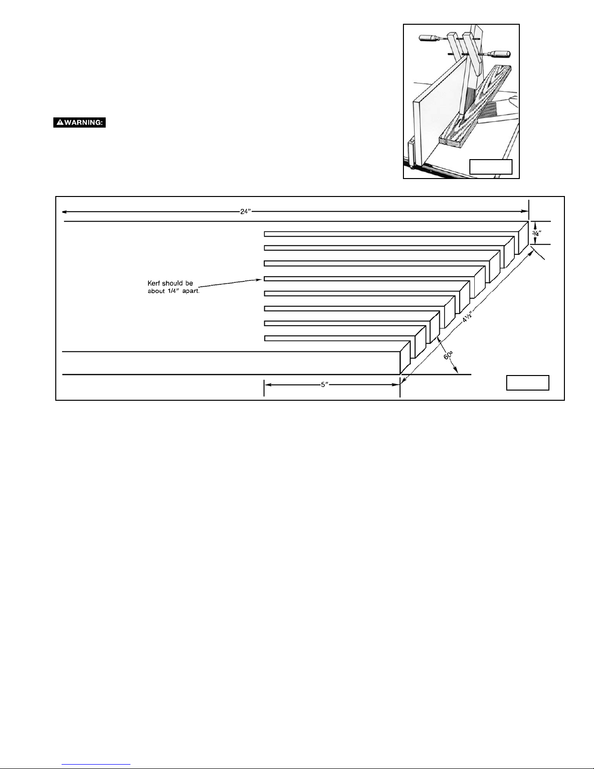
CONSTRUCTING A FEATHERBOARD
Featherboards are used to keep the work in contact with the fence and table (Fig.
69), and help prevent kickbacks. Dimensions for making a typical featherboard
are shown in Fig. 70. Make your featherboard from a straight piece of wood that
is free of knots and cracks. Clamp the featherboard to the fence and table so
that the leading edge of the featherboard will support the workpiece until the
cut is complete. An 8" high flat board can be clamped to the rip fence and the
featherboard can be clamped to the 8" high board.
guard and splitter assembly cannot be used. Always replace the guard and
Use featherboards for all non-thru-sawing operations where the
splitter assembly when the non-thru-sawing operation is complete. Make
sure the featherboard presses only on the portion of the workpiece in front
of the blade.
Fig. 69
Fig. 70
23
Page 24
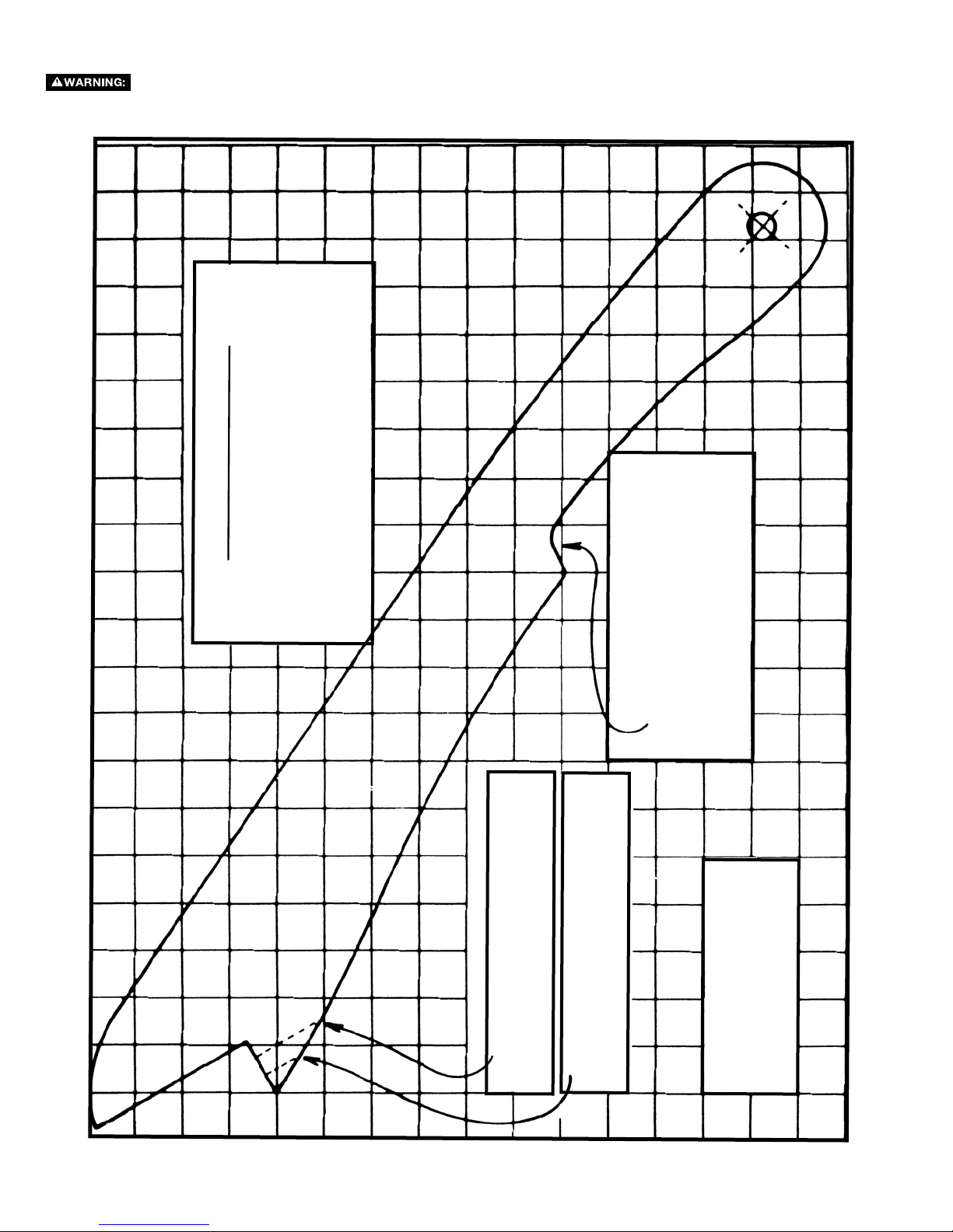
CONSTRUCTING A PUSH STICK
When ripping work less than 6" wide, use a push stick to complete the feed, You can make one from
scrap material by using this pattern.
"
OR 3/4
"
PUSH STICK
WOOD OR THICKNESS
MAKE FROM 1/2
LESS THAN WIDTH OF
MATERIAL TO BE CUT
WOOD
"
NOTCH TO HELP
WOOD
"
PREVENT HAND
FROM SLIPPING
24
CUT OFF HERE TO
PUSH 1/4
SQUARES
PUSH 1/2
CUT OFF HERE TO
"
1/2
Page 25

Further information on the safe and proper operation of table saws is available in the Delta “Getting the Most Out of
ELECTRICAL HAZARD.
HIGH VOLTAGE EXISTS
WITHIN THIS ENCLOSURE.
RISK OF ELECTRIC SHOCK.
DISCONNECT POWER
BEFORE OPENING DOOR OR
SERVICING.
PELIGRO DE DESCARGA ELÉCTRICA.
DENTRO DE LA CUBIERTA HAY PIEZAS CON
ALTO VOLTAJE.
RIESGO DE DESCARGA ELÉCTRICA.
DESCONECTE LA ALIMENTACIÓN ANTES DE
ABRIR LA PUERTA O REALIZAR TAREAS DE
MANTENIMIENTO.
RISQUE D’ORIGINE ÉLECTRIQUE.
UNE TENSION ÉLEVÉE EST PRÉSENTE À
L’INTÉRIEUR DE CE COFFRET.
RISQUE DE CHOC ÉLECTRIQUE.
COUPER L’ALIMENTATION AVANT D’OUVRIR
LA PORTE POUR MAINTENANCE.
Your Table Saw” How-To Book, Catalog No. 11-400. Additional Information on table saw safety, including a table saw
safety video, is available from the following:
POWER TOOL INSTITUTE
1300 Sumner Avenue
Cleveland, OH 44115-2851
www.powertoolinstitute.com
TROUBLESHOOTING
For assistance with your machine, visit our website at www.deltaportercable.com for a list of service centers or call the
DELTA Machinery help line at 1-800-223-7278 (In Canada call 1-800-463-3582).
SERVICE
REPLACEMENT PARTS
Use only identical replacement parts. For a parts list or to order parts, visit our website at
You can also order parts from your nearest factory-owned branch, or by calling our Customer Care Center at 1-800-223-7278 to
receive personalized support from highly-trained technicians.
FREE WARNING LABEL REPLACEMENT
If your warning labels become illegible or are missing, call
1-800-223-7278
for a free replacement.
www.deltaportercableservicenet.com.
SERVICE AND REPAIRS
All quality tools will eventually require servicing and/or replacement of parts. For information about Delta Machinery, its factoryowned branches, or an Authorized Warranty Service Center, visit our website at www.deltaportercable.com or call our Customer
Care Center at 1-800-223-7278. All repairs made by our service centers are fully guaranteed against defective material and
workmanship. We cannot guarantee repairs made or attempted by others.
You can also write to us for information at Delta Machinery, 4825 Highway 45 North, Jackson, Tennessee 38305 - Attention:
Product Service. Be sure to include all of the information shown on the nameplate of your tool (model number, type, serial number,
etc.)
25
Page 26

MAINTENANCE
KEEP MACHINE CLEAN
Periodically blow out all air passages with dry compressed air. All plastic parts should be cleaned with a soft damp cloth.
NEVER use solvents to clean plastic parts. They could possibly dissolve or otherwise damage the material.
Wear certified safety equipment for eye, hearing and respiratory protection while using compressed air.
FAILURE TO START
Should your machine fail to start, check to make sure the prongs on the cord plug are making good contact in the outlet. Also,
check for blown fuses or open circuit breakers in the line.
LUBRICATION & RUST PROTECTION
Apply household floor paste wax to the machine table, extension table or other work surface weekly. Or use a commercially
available protective product designed for this purpose. Follow the manufacturer’s instructions for use and safety.
To clean cast iron tables of rust, you will need the following materials: a sheet of medium Scotch-Brite
a can of WD-40
the table, then apply the protective product as described above.
®
and a can of degreaser. Apply the WD-40 and polish the table surface with the Scotch-Brite pad. Degrease
™ Blending Hand Pad,
ACCESSORIES
Since accessories other than those offered by Delta have not been tested with this product, use of
such accessories could be hazardous. For safest operation, only Delta recommended accessories should be used with
this product.
A complete line of accessories is available from your Delta Supplier, Porter-Cable • Delta Factory Service Centers, and Delta
Authorized Service Stations. Please visit our Web Site www.deltaportercable.com for a catalog or for the name of your
nearest supplier.
WARRANTY
To register your tool for warranty service visit our website at www.deltaportercable.com.
Two Year Limited New Product Warranty
Delta will repair or replace, at its expense and at its option, any new Delta machine, machine part, or machine accessory which in normal
use has proven to be defective in workmanship or material, provided that the customer returns the product prepaid to a Delta factory service
center or authorized service station with proof of purchase of the product within two years and provides Delta with reasonable opportunity
to verify the alleged defect by inspection. For all refurbished Delta product, the warranty period is 180 days. Delta may require that electric
motors be returned prepaid to a motor manufacturer’s authorized station for inspection and repair or replacement. Delta will not be responsible
for any asserted defect which has resulted from normal wear, misuse, abuse or repair or alteration made or specifically authorized by anyone
other than an authorized Delta service facility or representative. Under no circumstances will Delta be liable for incidental or consequential
damages resulting from defective products. This warranty is Delta’s sole warranty and sets forth the customer’s exclusive remedy, with respect
to defective products; all other warranties, express or implied, whether of merchantability, fitness for purpose, or otherwise, are expressly
disclaimed by Delta.
LATIN AMERICA: This warranty does not apply to products sold in Latin America. For products sold in Latin America, see coun-
try specific warranty information contained in the packaging, call the local company or see website for warranty information.
26
Page 27

LES INSTRUCTIONS IMPORTANTES DE SURETE
Lire toutes instructions d'avertissements et opération avant d'utiliser n'importe
quel outil ou n'importe quel équipement. En utilisant les outils ou l'équipement, les précautions de
sûreté fondamentales toujours devraient être suivies pour réduire le risque de blessure personnelle.
L'opération déplacée, l'entretien ou la modification d'outils ou d'équipement ont pour résultat la
blessure sérieux et les dommages de propriété. Il y a de certaines applications pour lequel outils et l'équipement
sont conçus. La Delta Machinery recommande avec force que ce produit n'ait pas modifié et/ou utilisé pour
l'application autrement que pour lequel il a été conçu.
Si vous avez n'importe quelles questions relatives à son application n'utilisent pas le produit jusqu'à ce que vous
avez écrit Delta Machinery et nous vous avons conseillé. La forme en ligne de contact à www.deltaportercable.com
Courrier Postal: Technical Service Manager, Delta Machinery, 4825 Highway 45 North, Jackson, TN 38305.
Mural St. Suite 300, Richmond Hill, ON, L4B 1M4.
Information en ce qui concerne l'opération sûre et correcte de cet outil est disponible des sources suivantes:
• Power Tool Institute, 1300 Sumner Avenue, Cleveland, OH 44115-2851 ou en ligne www.powertoolinstitute.org
• National Safety Council, 1121 Spring Lake Drive, Itasca, IL 60143-3201
• American National Standards Institute, 25 West 43rd Street, 4 floor, New York, NY 10036 www.ansi.org - ANSI 01.1
Safety Requirements for Woodworking Machines
• U.S. Department of Labor regulations www.osha.gov
Dans Canada, 125
MESURES DE SÉCURITÉ - DÉFINITIONS
Ce guide contient des renseignements importants que vous deviez bien saisir. Cette information porte sur VOTRE SÉCURITÉ
et sur LA PRÉVENTION DE PROBLÈMES D’ÉQUIPEMENT. Afin de vous aider à identifier cette information, nous avons
utilisé les symboles ci-dessous. Veuillez lire attentivement ce guide en portant une attention particulière à ces
sections.
Indique un danger imminent qui, s'il n'est pas évité, causera de graves blessures ou la mort.
Indique la possibilité d’un danger qui, s’il n’est pas évité, pourrait causer de graves blessures
ou la mort
dommages; mineures ou moyennes.
perçage et par toute autre activité de construction contiennent des produits chimiques reconnus par l’État de la
Californie comme pouvant causer le cancer, des anomalies congénitales ou d’autres problèmes liés aux fonctions
reproductrices. Voici quelques exemples de ces produits chimiques :
• leplombdespeinturesàbasedeplomb,
• lasilicecristallineprovenantdesbriques,ducimentetd’autresproduitsdemaçonnerieainsique,et
• l’arsenicetlechromeissusduboistraitéchimiquement.
Les risques reliés à l’exposition à ces produits chimiques varient selon la fréquence à laquelle l’utilisateur effectue ce type de
travail. Pour réduire l’exposition à ces produits chimiques : travailler dans un endroit bien ventilé et porter un équipement de
sécuritéapprouvé,notammentunmasqueantipoussièresconçuspécialementpourfiltrerlesparticulesmicroscopiques.
.
Indique la possibilité d’un danger qui, s’il n’est pas évité, peut causer des dommages à la propriété.
S
ans le symbole d’alerte.
Certaines poussières produites par les travaux de ponçage, de sciage, de meulage, de
Indique la possibilité d'un danger qui, s'il n'est pas évité,
peut causer des
27
Page 28

RÈGLES DE SÉCURITÉ GÉNÉRALES
L’inobservation de ces règles peut conduire à des blessures graves.
1. POUR SA SÉCURITÉ PERSONNELLE, LIRE LA NOTICE
D’UTILISATION, AVANT DE METTRE LA MACHINE EN MARCHE, et
pour aussi apprendre l’application et les limites de la machine ainsi que
les risques qui lui sont particuliers ainsi, les possibilités d’accident et de
blessures seront beaucoup réduites.
2. PORTEZ DES DISPOSITIFS DE PROTECTION DES YEUX ET DE
L'OUÏE. UTILISEZ TOUJOURS DES LUNETTES DE SÉCURITÉ. Des
lunettes ordinaires ne constituent PAS des lunettes de sécurité. UTILISEZ
DES ÉQUIPEMENTS DE SÛRETÉ HOMOLOGUÉS. Les dispositifs de
protection des yeux doivent être conformes aux normes ANSI Z87.1. Les
dispositifs de protection de l'ouïe doivent être conformes aux normes
ANSI S3.19.
3. PORTER UNE TENUE APPROPRIÉE. Pas de cravates, de gants, ni
de vêtements amples. Enlever montre, bagues et autres bijoux. Rouler
les manches. Les vêtements ou les bijoux qui se trouvent pris dans les
pièces mobiles peuvent entraîner des blessures.
4. NE PAS UTILISER LA MACHINE DANS UN ENVIRONNEMENT
DANGEREUX. L’utilisation d’outils électriques dans des endroits
humides ou sous la pluie peut entraîner des décharges électriques ou
une électrocution. Garder la zone de travail bien éclairée pour éviter de
trébucher ou d’exposer les doigts, les mains ou les bras à une situation
dangereuse.
5. GARDER LES OUTILS ET LES MACHINES EN PARFAIT ÉTAT.
Garder les outils affûtés et propres afin d’obtenir le meilleur et le plus
sûr rendement. Suivre les instructions pour lubrifier et changer les
accessoires. Les outils et les machines mal entretenus peuvent se
dégrader davantage, et/ou entraîner des blessures.
6. INSPECTER LES PIÈCES POUR DÉCELER TOUT DOMMAGE.
Avant d’utiliser la machine, la vérifier pour voir s’il n’y a pas de pièces
endommagées. Vérifier l’alignement des pièces mobiles et si ces pièces
ne se coincent pas, la rupture de pièces, ou toute autre condition pouvant
en affecter le fonctionnement. Toute pièce ou protecteur endommagé doit
être réparé ou remplacé. Les pièces endommagées peuvent dégrader
davantage la machine et/ou entraîner des blessures.
7. GARDER L’AIRE DE TRAVAIL PROPRE. Les zones et établis
encombrés favorisent les accidents.
8. GARDER LES ENFANTS ET LES VISITEURS À DISTANCE. L’atelier est
un lieu potentiellement dangereux. Les enfants et les visiteurs peuvent se
blesser.
9. ÉVITER LE DÉMARRAGE ACCIDENTEL. S’assurer que l’interrupteur
est sur « OFF » (ARRÊT) avant de brancher le cordon. En cas de coupure
de courant, placer l’interrupteur à la position « OFF » (ARRÊT). Un
démarrage accidentel peut entraîner des blessures.
10. UTILISER LES DISPOSITIFS PROTECTEURS. Vérifier que tous les
dispositifs protecteurs sont bien en place, bien fixés et en bon état de
marche pour éviter les blessures.
11. ENLEVER LES CLÉS DE RÉGLAGE ET CELLES DE SERRAGE AVANT
DE METTRE LA MACHINE EN MARCHE. Les outils, les chutes et les
autres débris peuvent être projetés violemment et blesser.
12. UTILISER LA BONNE MACHINE. Ne pas forcer la machine ou
l’accessoire à faire un travail pour lequel il n’a pas été conçu. Des
dommages à la machine et/ou des blessures pourraient s’ensuivre.
13. UTILISER LES ACCESSOIRES RECOMMANDÉS. L’utilisation
d’accessoires non recommandés par Delta peut endommager la machine
et blesser l’utilisateur.
14. UTILISER LE CORDON PROLONGATEUR APPROPRIÉ. S’assurer
que le cordon prolongateur est en bon état. Lorsqu’un cordon
prolongateur est utilisé, s’assurer que celui-ci est d’un calibre suffisant
pour l’alimentation nécessaire à la machine. Un cordon d’un calibre
insuffisant entraînera une perte de tension d’où une perte de puissance
et surchauffe. Voir le tableau sur les cordons prolongateurs pour obtenir
le calibre approprié selon la longueur du cordon et l’ampérage de la
machine. S’il y a un doute, utiliser un cordon d’un calibre supérieur. Plus
le chiffre est petit, plus le fil est gros.
15. FIXER LA PIÈCE. Utilisez les brides ou l'étau quand vous ne pouvez pas
fixer l'objet sur la table et contre la barrière à la main ou quand votre main
sera dangereusement près de la lame (à moins de 6").
16. AVANCER LA PIÈCE DANS LE SENS CONTRAIRE À LA ROTATION
DE LA LAME, DE LA FRAISE OU DE LA SURFACE ABRASIVE.
L’alimentation dans l’autre sens peut entraîner une projection violente de
la pièce.
17. NE PAS FORCER LA MACHINE EN AVANÇANT LA PIÈCE TROP
VITE. Des dommages et/ou des blessures peuvent s’ensuivre.
18. NE PAS SE PENCHER AU-DESSUS DE LA MACHINE. Une perte de
l’équilibre peut entraîner une chute sur la machine en marche et causer
des blessures.
19. NE JAMAIS MONTER SUR LA MACHINE. On peut se blesser
gravement si la machine bascule ou si l’on touche accidentellement son
outil tranchant.
20. NE JAMAIS LAISSER LA MACHINE EN MARCHE SANS
SURVEILLANCE. COUPER LE COURANT. Ne pas quitter la machine
tant qu’elle n’est pas complètement arrêtée. Un enfant ou un visiteur
pourrait se blesser.
21. METTRE LA MACHINE À L’ARRÊT « OFF » ET LA DÉBRANCHER
avant d’installer ou d’enlever des accessoires, d’ajuster ou de changer
des montages, ou lors des réparations. Un démarrage accidentel peut
entraîner des blessures.
22. METTRE L’ATELIER À L’ABRI DES ENFANTS AU MOYEN DE
CADENAS, D’INTERRUPTEURS PRINCIPAUX OU EN ENLEVANT
LES BOUTONS DES DISPOSITIFS DE MISE EN MARCHE. Le
démarrage accidentel de la machine par un enfant ou un visiteur peut
entraîner des blessures.
23. RESTER VIGILANT, ATTENTIF, ET FAIRE PREUVE DE BON SENS.
NE PAS UTILISER LA MACHINE LORSQUE L’ON EST FATIGUÉ
OU SOUS L’INFLUENCE DE DROGUES, D’ALCOOL OU DE
MÉDICAMENTS. Un instant d’inattention lors de l’utilisation d’outils
électriques peut entraîner des blessures graves.
24.
PRODUIRE ET DISPERSER DE LA POUSSIÈRE OU D'AUTRES
PARTICULES EN SUSPENSION DANS L'AIR, TELLES QUE LA
SCIURE DE BOIS, LA POUSSIÈRE DE SILICIUM CRISTALLIN ET
LA POUSSIÈRE D'AMIANTE. Dirigez les particules loin du visage
et du corps. Faites toujours fonctionner l'outil dans un espace bien
ventilé et prévoyez l'évacuation de la poussière. Utilisez un système de
dépoussiérage chaque fois que possible. L'exposition à la poussière
peut causer des problèmes de santé graves et permanents, respiratoires
ou autres, tels que la silicose (une maladie pulmonaire grave) et le
cancer, et même le décès de la personne affectée. Évitez de respirer de
la poussière et de rester en contact prolongé avec celle-ci. En laissant
la poussière pénétrer dans vos yeux ou votre bouche, ou en la laissant
reposer sur votre peau, vous risquez de promouvoir l'absorption de
substances toxiques. Portez toujours des dispositifs de protection
respiratoire homologués par NIOSH/OSHA, appropriés à l'exposition à la
poussière et de taille appropriée, et lavez à l'eau et au savon les surfaces
de votre corps qui ont été exposées.
L'UTILISATION DE CET OUTIL PEUT
28
Page 29

RÈGLES SPÉCIFIQUES ADDITIONNELLES DE SÛRETÉ
L’inobservation de ces règles peut conduire à des blessures graves.
1. NE PAS FAIRE FONCTIONNER CETTE MACHINE avant qu’elle
ne soit entièrement assemblée et installée conformément à ces
directives.
2. DEMANDER CONSEIL À UN SUPERVISEUR, instructeur,
ou toute autre personne qualifiée si vous ne maîtrisez pas
parfaitement l’utilisation de cette machine.
3. SUIVRE TOUS LES CODES DE CÂBLAGE et les connexions
électriques recommandées.
4. TOUJOURS UTILISER LES PARE-MAINS, LE COUTEAU
SÉPARATEUR, ET LES CLIQUETS ANTI-EFFET DE REBOND
chaque fois que possible, y compris tout débitage complet.
Vérifier qu’ils sont bien en place, fixés et qu’ils fonctionnent
correctement. Effectuer un essai du fonctionnement du cliquet
anti-effet de rebond avant de scier en long en poussant la pièce
de bois sous les dents anti-effet de rebond. Les dents doivent
empêcher la projection de la pièce de bois vers l’avant de la scie.
5. LA COUPE DE L’OUVRAGE SANS UTILISER DE GUIDE OU
DE JAUGE À ONGLET EST APPELÉE COUPE « À MAINS
LIBRES ». NE JAMAIS effectuer d’opération « à mains libres ».
Utiliser le guide ou la jauge à onglet pour positionner et guider
l’ouvrage.
6. TENIR FERMEMENT L’OUVRAGE contre la jauge à onglet ou le
guide.
7. L’ACTION DE COUPER COMPLÈTEMENT À TRAVERS
L’OUVRAGE EST APPELÉ « DÉBITAGE COMPLET ». Le sciage
en long et la coupe transversale sont des opérations de débitage
complet. L’action de couper dans le sens du fil s’appelle sciage
en long. Utiliser un guide ou un système de guidage pour scier
en long. NE JAMAIS utiliser une jauge à onglet pour le sciage en
long. Utiliser des poussoirs pour scier en long un ouvrage étroit.
L’actionde couper à contrefil s’appelle tronçonnage. Ne jamais
utiliser un guide ou un système de guidage pour tronçonner.
Utiliser plutôt une jauge à onglet.
8. L’EFFET DE REBOND EST LE FAIT QUE L’OUVRAGE A
NATURELLEMENT TENDANCE À ÊTRE PROJETÉ VERS
L’OPÉRATEUR après avoir heurté ou pincé la lame. L’effet de
rebond est dangereux et peut résulter en de graves blessures.
POUR ÉVITER L’EFFET DE REBOND :
A. maintenir la lame affûtée, exempte de rouille ou de résine.
B. garder le guide longitudinal parallèle à la lame de la scie.
C. utiliser un pare-main et un couteau séparateur pour toutes
les opérations demandant leur utilisation, y compris tout
débitage complet.
D. maintenir le couteau séparateur aligné avec la lame de la
scie.
E. maintenir les cliquets anti-effet de rebond en place et bien
affûtés
F. pousser l’ouvrage pour qu’il dépasse de la lame avant la
relâche.
G. ne jamais scier en long un ouvrage tordu ou déformé, ou
n’ayant pas un bord droit qui permette de le déplacer le long
du guide.
H. utiliser des planches en éventail lorsque le dispositif anti-
effet de rebond ou le pare-main et le couteau séparateur ne
peuvent être utilisés.
I. ne jamais scier un gros ouvrage dont on ne peut pas assurer
le contrôle.
J. ne jamais utiliser le guide comme pare-main pour un
tronçonnage.
K. ne jamais scier un ouvrage à noeud vicieux, avec défauts,
clous ou tout autre corps étranger.
L. ne jamais scier en long un ouvrage de moins de 254 mm
(10 po).
CERTAINS MATÉRIAUX SONT TROP DURS
ET GLISSANTS POUR UN FONCTIONNEMENT EFFICACE DES
CLIQUETS ANTI-EFFET DE REBOND. Le plastique et les composés
(tel un panneau pressé) peuvent être coupée par la scie. Toutefois,
être particulièrement attentif et effectuer tous les réglages adéquats
et suivre les procédures de sciage pour empêcher tout rebond lors du
sciage de ces matériaux.
9. UTILISER LA LAME DE SCIE APPROPRIÉE POUR
L’UTILISATION PRÉVUE À CET EFFET. La lame doit tourner
vers l’avant de la scie. Toujours serrer solidement l’écrou d’axe de
la lame. Avant l’utilisation, inspecter la lame pour des fissures ou
des dents manquantes. Ne pas utiliser de lame endommagée.
10. NE JAMAIS UTILISER DE MEULES ABRASIVES sur cette scie.
11. NE PAS COUPER DE MÉTAL AVEC CETTE SCIE.
12. DÉGAGER LA TABLE DES PIÈCES COUPÉES ET CHUTES
avant de démarrer la scie. Les vibrations de la machine peuvent
les entraîner vers la lame de la scie et les projeter.
13. LES PIÈCES COUPÉES PEUVENT -TRE PROJETÉES VERS
L’OPÉRATEUR. Pour les grandes pièces coupées, utiliser un
poussoir pour pousser la pièce au-delà de la lame puis vers
l’arrière de la table de la scie. Ne pas se pencher au-dessus de la
table pour atteindre l’autre côté. -tre attentif et empêcher que de
petits morceaux ne touchent la lame.
14. NE JAMAIS TENTER DE DÉBLOQUER UNE LAME COINCÉE
SANS AVOIR ÉTEINT LA MACHINE AU PRÉALABLE. Si un
ouvrage ou une pièce coupée se coince à l’intérieur du pare-main,
éteindre la scie et attendre que la lame s’arrête avant de soulever
le pare-main pour retirer la pièce.
15. NE JAMAIS DÉMARRER LA MACHINE avec l’ouvrage contre la
lame.
16. NE JAMAIS placer l’ouvrage entre le guide et la fraise à moulurer.
17. TENIR LES BRAS, MAINS, ET DOIGTS éloignés de la lame.
Utiliser un poussoir pour pousser les petits ouvrages sous la scie.
Un poussoir est un petit bâton de bois, normalement fait maison,
qui s’utilise pour éviter d’approcher vos mains à près de 15,2 cm
(6 po) de la lame à chaque fois que la taille ou la forme de
l’ouvrage l’exige. Consulter « FABRICATION D’UN POUSSOIR »
à la fin de ce mode d’emploi pour les directives relatives à la
fabrication de votre propre poussoir.
18. ÉVITER LES OPÉRATIONS MALADROITES ET ÉVITER D’AVOIR
LES MAINS MAL PLACÉES : en glissant soudainement, une
main pourrait percuter la lame.
19. AUCUNE partie du corps ne doit se trouver dans la trajectoire de
la lame de la scie.
20. NE PAS LAISSER LES MAINS AUTOUR de la lame ou sur celle-
ci.
21. SOUTENIR CORRECTEMENT LES OUVRAGES LONGS (91 cm
(3 pi) ou plus) OU LARGES (91 cm (36 po) ou plus). Si des
tables extensibles plus larges que 61 cm (24 po) sont reliées à
la scie, boulonner le socle de la scie au plancher ou utiliser des
stabilisateurs robustes pour empêcher le basculement.
22. EMP-CHER LES MOUVEMENTS DE LA SCIE EN COURS
D’UTILISATION. Si les accessoires de la trousse de mobilité
sont installés, abaisser la commande à pieds et mettre les pieds
de la table à niveau de sorte que la scie ne puisse balancer,
« marcher », glisser ou basculer. Le cas échéant, fixer solidement
le socle au plancher.
23. NE JAMAIS EFFECTUER D’OPÉRATION DE TRAÇAGE,
d’assemblage, ou de réglage sur la table/l’espace de travail
lorsque la machine est en marche.
24. ÉTEINDRE L’APPAREIL ET LE DÉBRANCHER DE LA SOURCE
D’ALIMENTATION avant de poser ou de retirer tout accessoire,
de changer la lame de la scie ou d’ajuster ou modifier les réglages.
Verrouiller l’interrupteur en position d’arrêt (« OFF ») au cours de
réparations.
25. NETTOYER LA TABLE/ESPACE DE TRAVAIL AVANT DE
LAISSER LA MACHINE. Verrouiller l’interrupteur en position
d’arrêt afin d’éviter toute utilisation non autorisée.
26. DES INFORMATIONS SUPPLÉMENTAIRES (i.e. une vidéo sur
la sécurité), indiquant comment utiliser des outils électriques
correctement et en toute sécurité, sont disponibles auprès
du Power Tool Institute, 1300 Sumner Avenue, Cleveland, OH
44115-2851, États-Unis (www.powertoolinstitute.com). Vous
pouvez également vous procurer des informations auprès du
National Safety Council, 1121 Spring Lake Drive, Itasca, IL
60143-3201, États-Unis. Veuillez vous reporter à la norme ANSI
01.01 de l’American National Standards Institute concernant les
machines de travail du bois, ainsi que la réglementation OSHA
1910.213 du département américain du travail.
CONSERVER CES DIRECTIVES.
Les consulter souvent et les utiliser pour donner des
directives aux autres.
29
Page 30

FICHE TECHNIQUE DU MOTEUR
Le modèle 36-790 est doté d’un moteur triphasé de 7.5 cv et précâblé pour une tension de 230 V, 60 Hz. On peut
recâbler l’appareil pour une tension de 460 V o 208 V, 60 Hz.
CONNEXIONS ÉLECTRIQUES
pour réduire le risque de blessures, éteindre l’appareil et le débrancher avant d’installer ou de retirer
tout accessoire et avant d’effectuer des réglages ou des réparations. Un démarrage accidentel peut provoquer des
blessures
Lemodèle36-790n’estpaspourvud’uncordond’alimentation.Ilestconçupouruneconnexionpermanenteàlasource
d’alimentation. Tous les raccordements électriques doivent être réalisés par un électricien professionnel conformément
au Code national de l’électricité ainsi qu’aux codes et aux ordonnances locaux. TOUJOURS METTRE L’APPAREIL
HORS TENSION AVANT DE LE RÉPARER.
graves.
REMARQUES À L’INTENTION DE
L’ÉLECTRICIEN
Utiliser un cordon flexible à trois conducteurs pour
service intense ou léger, de calibre minimum (AWG) de
10, avec mise à la terre, pour raccorder l’appareil à un
circuit de dérivation protégé convenant à un moteur à
induction triphasé de 7,5 hp, 208-230/460 V. Le moteur
est câblé pour une alimentation en c.a. de 60 Hz,
208-230 V. Relier L1, L2 et L3 aux bornes du bloc de
jonction portant les inscriptions R, S et T (fig. A1) et le
conducteur de terre à la borne. Serrer les vis des bornes
du bloc de jonction au couple de 4,5-7,0 lb-po. Faire
fonctionner l’interrupteur par à-coups et vérifier si la
rotation de la lame est adéquate (la courbure de la lame
devrait tourner vers l’avant de l’outil). Échanger deux fils
de sortie pour faire marche arrière.
INSTRUCTIONS DE MISE À LA TERRE
l’appareil doit être mis à la terre lors
de son utilisation afin de protéger l’utilisateur contre
tout choc électrique.
Il faut relier l’outil à un système de câblage, avec mise
à la terre métallique permanente, ou à un système muni
d’un conducteur de terre. Insérer le fil du conducteur
de terre dans la borne (mise à la terre) de la plaque
à bornes. S’assurer que l’autre extrémité est solidement
fixée à la prise de terre du circuit de dérivation.
FONCTIONNEMENT AVEC UNE TENSION DE
460 VOLTS
Cet appareil peut également fonctionner à partir d’une
source de 60 Hz, 460 V en modifiant les connexions.
(A) Rebrancher le moteur pour 460 V, selon le schéma
de câblage de la plaque signalétique du moteur.
(B) Changer la prise de tension du primaire de la borne
« 3 » (230 V) à la borne « 4 » (460 V) (fig. A2).
(C) Remplacer le relais de surcharge de 15-23 A par un
autre de 8-12 A réglé à un déclenchement de 9 A
(fig. A3).
Serrer les vis du relais de surcharge et des bornes du
contacteur au couple de 14,2 à 26,6 lb-po. Régler le
relais de surcharge à réenclenchement automatique.
Fig. A2
Fig. A1
Fig. A3
FONCTIONNEMENT AVEC UNE TENSION DE
208 VOLTS
Il est possible d’utiliser l’appareil à partir d’une
alimentation de 60 Hz, 208 V, à la condition que l’intensité
de déclenchement du relais de surcharge (fig. A5) soit
réglé à 20 A et que la prise de tension du primaire du
transformateur passe de la borne « 3 » à la borne « 2 »
(208 V) (fig. A4).
Fig. A4 Fig. A5
30
Page 31

Pour réduire le risque de blessures graves, d’électrocution ou de dommages matériels, ne
C
1
COM
5
COM
6
24V
4
3
2
460V
230V
208V
Connect as per line
voltage
N
R
S
T
M
2T
1
4T
2
6T
3
4N
O
3N
O
A2
A1
T1
T2
T3
4
5
6
95
NC
96
NC
1L
1
3L
2
5L
3
Connection made by
user
TR
OL
OL
CB
b0
b1
COMPONENTS
b 0
Off Switch
b 1
On Switch
C
Contactor
CB
Circuit Breaker
M
Motor
OL
Overload
Terminal Block
C
C
TR Transformer
pas tenter d’effectuer le raccordement électrique de cet appareil. Le schéma fourni est destiné à l’usage exclusif
d’un électricien professionnel.
Circuit du moteur
Protection de surcharge
Plaque à bornes
Transformateur
COMPOSANTS
Commutateur d’arrêt
Commutateur de mise en marche
Contacteur
Disjoncteur
Raccorder en fonction de la
Connexion effectuée par
l’utilisateur
tension secteur
31
Page 32

DESCRIPTION FONCTIONNELLE
AVANT-PROPOS
La scie articulée de 356 mm (14 po), modèle industriel 36-790 Delta, comprend un démarreur magnétique pourvu d’un
dispositif de commande à basse tension et d’un rupteur thermique à réenclenchement automatique, un système de
guide commercial Biesemeyer®, un rail de guidage, un guide d’onglets, une table avec deux rallonges de 1,09 m x 1,5 m
(43 po x 59 po) et une rallonge de support de guide. On peut aussi utiliser une lame de 406 mm (16 po) pour accroître
la capacité de coupe. La profondeur de coupe maximale pour une lame de 356 mm (14 po) est de 114 mm (4 1/2 po)
et pour une lame de 406 mm (16 po), 140 mm (5 1/2 po) de profondeur. À un angle de 45°, l’épaisseur maximale de
coupe pour une lame de 356 mm (14 po) est de 79 mm (3 1/8 po) et de 105 mm (4 1/8 po) pour une lame de 406 mm
(16 po).
REMARQUE : La image sur la couverture illustre le modèle de production actuel. Les autres illustrations de ce mode
d’emploi ne sont présentes qu’à titre indicatif et il est possible que les étiquettes et accessoires actuels diffèrent des caractéristiques réelles de ce modèle. Ces illustrations ont uniquement pour but d’illustrer la technique.
CONTENUS DE BOITE
2
4
1
6
5
1. Ferrure de support du guide longitudinal
2. Protège-lame
3. Rallonges de table
4. Couteau séparateur
5. Support de montage de couteau séparateur
6. Guide d’onglet
7. Ensemble de tige à butée
8. Clé à fourche de 17 mm et de 19 mm
9. Boulon à tête hexagonale M11 x 35 mm
10. Écrou M6
11. Boulon à tête hexagonale M8 x 25 mm
12. Rondelles plates de 8 mm
13. Rondelles plates M10
14. Boulons à tête hexagonale M6 x 20 mm
15. Poignée
7
9
11
13
15
3
8
10
12
14
32
Page 33

7
4
5
6
8
10
1. Barre de guidage avant
2. Tube de guidage
3. Assemblage du guide
4. Boulons à tête plate de 1/2 po-13 x 2 po
5. Clé hexagonale de 5/16 po
6. (2) rondelles plates de 1/2 po
3
7. Écrous hexagonaux de 1/2 po-13
8. Rondelle de blocage
9. Écrou de retenue
10. Rondelle de blocage
11. Boulon à écrou de retenue
9
11
1
2
DÉSEMBALLAGE ET NETTOYAGE
Désemballer soigneusement la machine et toutes les pièces de ou des emballage(s) d’expédition. Retirer l’huile anticorrosion des surfaces non peintes à l’aide d’un chiffon doux humidifié avec de l’alcool, du diluant à peinture ou de
l’alcool dénaturé.
N’utiliser pas de solvants hautement volatils tel l’essence, le naphte, l’acétone ou du diluant à
laque pour nettoyer.
Après nettoyage, couvrir les surfaces non peintes d’une cire à parquets d’usage domestique de bonne qualité.
Pour réduire le risque de blessures corporelles graves, éteindre l’outil et le débrancher avant
d’installer et de retirer tout accessoire, avant d'ajuster ou de modifier les réglages ou lors de réparations. Un démar-
rage accidentel peut provoquer des blessures.
OUTILS NÉCESSAIRES POUR L’ASSEMBLEE
L'ESTIMATION DE TEMPS D'ASSEMBLEE
L’assemblage de l’appareil prend environ deux à trois heures.
ASSEMBLAGE
Clé à fourche de 17 mm et de 19 mm (fournie)
Clé de lame (fournie)
33
Page 34

IMPORTANT - Avant d’assembler cet appareil, enlever
les deux boulons (A) fig. 1, et la sangle d’expédition rouge
(B). Ce support protège le moteur durant l’expédition.
FIXATION DE LA POIGNÉE AU MÉCANISME
ÉLÉVATEUR
Insérer l’extrémité filetée de la poignée (A) fig. 2, dans le
trou fileté du volant élévateur (B), puis bien la serrer en la
tournant dans le sens horaire.
FIXATION DES RALLONGES DE LA TABLE
Les rallonges de la table sont très
lourdes. Utiliser un appareil de levage (fig. 3) pour soulever
et tenir la table à rallonges en place durant l’installation.
Cet appareil est fourni avec deux rallonges de table. Fixer la rallonge à l’aide des deux trous taraudés (A) fig. 4,
pratiqués sur le côté droit de l’appareil.
A
B
Fig. 1
A
B
Fig. 2
Fig. 3
Fig. 4
34
Page 35

A
B
C
A
Fig. 5
Fixer la rallonge à la scie à l’aide de trois boulons à tête hexagonale de 35 mm x M10 (A) fig. 5.
Remarque : visser lâchement les boulons pour un réglage ultérieur.
Placer une règle droite (A) fig. 6, sur la scie (B) et la table à rallonges (C), au-dessus du premier boulon pour vérifier le
niveau. Lorsque les deux boulons sont au niveau, les serrer. Suivre la même procédure pour le boulon plus éloigné. Serrer solidement toute la boulonnerie.
Installer l’autre rallonge selon la même procédure.
Fig. 6
FIXATION DE LA FERRURE DE SUPPORT DU GUIDE LONGITUDINAL
A
C
B
AA
B
Fig. 7
Fixer la ferrure du support du guide longitudinal (A) fig. 7, à la scie (B) à l’aide de deux boulons à tête hexagonale de
35 mm x M8 (C) fig. 7.
Remarque : visser lâchement les boulons pour un réglage ultérieur.
Mettre une règle droite sur la scie (B) et la ferrure du support du guide (A) pour vérifier le niveau. Lorsque les deux
boulons sont au niveau, les serrer. Serrer solidement toute la boulonnerie.
Fig. 8
FIXATION DE LA LAME DE SCIE
REMARQUE : aucune lame n’est fournie avec cette
scie.
1. Enlever la plaque amovible et relever complètement
l’arbre de scie circulaire en tournant le volant qui
hausse la lame.
REMARQUE : tourner le boulon de l’arbre dans le sens
horaire pour le desserrer.
2. Utiliser la clé de lame fournie pour enlever le boulon
de l’arbre (A), le dispositif de fixation (B), la cale (C)
et la bride de lame (D).
REMARQUE : laisser la bride de lame intérieure (E) sur
l’arbre.
REMARQUE : enfoncer le bouton de la commande de
verrouillage (A) fig. 11, pour immobiliser l’arbre.
A
B
C
D
E
Fig. 9
35
Page 36

3. Placer la lame de la scie (A) fig. 10, de sorte que les dents pointent vers l’avant de la scie, contre la bride de lame
C
intérieure (B).
4. Ajouter la bride de lame extérieure (C), la cale (D), le dispositif de fixation (E) et le boulon de l’arbre (F).
5. Enfoncer le bouton de verrouillage de l’arbre (A) fig. 11, et bien serrer le boulon de l’arbre en le tournant dans le
sens antihoraire.
F
D
A
E
Fig. 10
B
Fig. 11
A
FIXATION DU PROTÈGE-LAME ET DE L’ENSEMBLE DE COUTEAU SÉPARATEUR
IMPORTANT : la largeur de la lame détermine la bonne position du couteau séparateur sur le support de fixation.
1. Desserrer les deux boulons (A) fig. 12.
REMARQUE : le support de fixation du couteau séparateur comporte trois tailles distinctes de cales.
2. Placer une règle droite (A) fig. 13, contre le dos de la lame. Aligner la lame avec le couteau séparateur.
3. Mettre le couteau séparateur à l’emplacement indiqué, avec les cales, du support de fixation du couteau séparateur.
REMARQUE : positionner le couteau séparateur à environ 3 mm (1/8 po) au-dessus de la surface de la table.
4. Utiliser la clé pour arbre (A) fig. 14, comme cale. La mettre entre le couteau séparateur (B) et la surface de la table
(C). Serrer les deux boulons (A) fig. 12.
5. Utiliser les quatre vis à tête hexagonale M6 x 20 mm (A) fig. 15, les huit rondelles plates et les quatre écrous hex-
agonaux pour fixer le support du couteau séparateur (C) fig. 15, au couteau séparateur (D).
6. Utiliser les deux boulons à tête hexagonale M6 x 25 mm (B) fig. 15, quatre rondelles plates et deux écrous hexago-
naux pour fixer l’ensemble de support de couteau séparateur à la bride.
REMARQUE : visser lâchement la boulonnerie pour un réglage ultérieur.
A
Fig. 12 Fig. 13
B
C
A
D
AB
C
Fig. 14
A
Fig. 15
36
Page 37

6. Baisser la lame et fixer la plaque amovible (A) fig. 16,
à la table de la scie. Utiliser une règle droite (B) pour
voir si la plaque amovible (A) affleure la surface de
la table (C). Mettre au niveau la plaque amovible en
tournant les boulons hexagonaux requis (D).
B
D
7. Utiliser la clé pour arbre comme cale pour régler la
hauteur du linguet antirecul (A) fig. 17. Mettre la clé
sous le linguet antirecul, desserrer la vis (B) et régler
la came (C) de sorte que le linguet antirecul (A) pointe
vers l’arrière et ne touche pas à la table. Régler l’autre
linguetantireculdelamêmefaçon.
IMPORTANT : tourner la poignée de biseautage de lame
de sorte que la lame soit à 45°. Vérifier le linguet antirecul
et s’assurer qu’il ne touche pas à la table.
8. Utiliser une règle droite (A) fig. 18, pour voir si le couteau séparateur (B) est aligné avec la lame (C). Serrer
les boulons de montage.
9. Enlever les deux boulons (A), fig. 19, du sommet du
couteau séparateur (B). Fixer l’ensemble du panier
du protège-lame fig. 20, au couteau séparateur à
l’aide des deux boulons.
B
D
A
C
Fig. 16
C
A
Fig. 17
A
B
Fig. 19
A
Fig. 18
B
C
Fig. 20
37
Page 38

FIXATION DU RAIL DE GUIDAGE DU GUIDE LONGITUDINAL
1. Utiliser trois (3) boulons à tête plate de 1/2 po-13 X 2 po, des rondelles plates, des rondelles de blocage et des
écrous hexagonaux (A) fig. 21, pour fixer le rail de guidage à l’avant de la table de scie (fig. 22). Visser lâchement
avec la clé hexagonale fournie pour un réglage ultérieur.
A
Fig. 21
2. Utiliser le gabarit (A), fig. 23, fourni avec le système
de guide pour vérifier le niveau du rail avant (B) aux
deux extrémités de la table de scie. Visser solidement la boulonnerie du rail de guidage.
REMARQUE : NE PAS mettre le rail au niveau avec la
rallonge. Utiliser la table de scie.
3. Mettre le tube de guidage (A) fig. 24, sur la table de
scie. Aligner les neuf (9) trous filetés avec les trous
pratiqués dans la pièce d’appui avant.
4. Positionner le tube de guidage sur le rail avant. Fixer
le tube de guidage à l’aide des neuf (9) boulons à
tête hexagonale de 1/2 po et des rondelles de blocage.
5. Mettre le guide longitudinal sur le rail de guidage.
6. Insérer un boulon (A) fig. 26, dans le trou (B) logé à
l’extrême droite du tube de guidage. Enfiler l’écrou
de retenue (C) sur le boulon (voir le médaillon - fig.
26)
REMARQUE : cet écrou de retenue empêche le guide de
tomber de l’extrémité du rail de guidage.
IMPORTANT : avant de mettre la scie sous tension,
s’assurer que le guide longitudinal est parallèle à la
rainure du guide d’onglets. Se reporter à la rubrique
« FONCTIONNEMENT ET RÉGLAGE DU GUIDE
LONGITUDINAL ».
A
B
Fig. 22
Fig. 23
A
Fig. 24
Fig. 25
B
A
C
Fig. 26
38
Page 39

FIXATION DU GUIDE D’ONGLETS ET DE L’ENSEMBLE DE TIGE À BUTÉE
1. Insérer la barre du guide d’onglets (A) fig. 27, dans la rainure en T de la table de scie. La barre du guide d’onglets
insérée dans la rainure en T empêchera le guide d’onglets de tomber lorsqu’il est déployé au-delà de la surface de
la table.
2. Desserrer le bouton de verrouillage (A) fig. 28, et insérer l’extrémité de la tige à butée (D) dans le trou pratiqué sur le
côté du corps du guide d’onglets.
3. Serrer le bouton de verrouillage (A) fig. 28.
A
Fig. 27
A
D
FONCTIONNEMENT
L'OPERATION CONTROLE DE LE ET LES AJUSTEMENTS
DÉMARRAGE ET ARRÊT DE L’APPAREIL
L’interrupteur marche/arrêt est logé à l’avant de l’appareil.
Pour démarrer l’appareil, enfoncer le bouton vert (A). Pour
arrêter l’appareil, enfoncer le gros bouton rouge (B).
PROTECTION CONTRE LES SURCHARGES
Cet appareil arrêtera le moteur en cas de surcharge ou
de basse tension. Si l’appareil s’arrête, le laisser refroidir
pendant cinq minutes, puis enfoncer le bouton vert de
mise en marche.
IMPORTANT : si la scie s’arrête fréquemment, demander
à un électricien professionnel de trouver le problème et
de le corriger.
REMPLACEMENT DE LA LAME
Couper l’alimentation vers l’appareil.
A
B
Fig. 28
Fig. 29
1. Enlever le protège-lame et la plaque amovible.
REMARQUE : enlever l’ensemble de couteau séparateur
UNIQUEMENT si l’épaisseur de la lame de rechange diffère de
la lame d’origine.
2. Hausser complètement la lame.
3. Enfoncer le bouton de verrouillage de l’arbre et utiliser la
clé de l’arbre fournie pour enlever le boulon de l’arbre.
Tourner la clé vers l’avant de la scie.
4. Positionner la lame neuve sur l’arbre de la scie. Remettre
la bride de lame, la cale, le dispositif de fixation et le boulon de l’arbre.
5. Enfoncer le bouton de verrouillage de l’arbre, puis serrer
l’ensemble de lame en tournant la clé vers l’arrière de la
scie.
6. Remettre la plaque amovible et le protège-lame. Si
vous avez enlevé l’ensemble de couteau séparateur, le
remettre.
REMARQUE : si la lame neuve présente une épaisseur différente de l’ancienne lame, se reporter à la rubrique « FIXATION
DU PROTÈGE-LAME ET DE L’ENSEMBLE DE COUTEAU
SÉPARATEUR » pour bien placer le couteau séparateur.
Fig. 30
Fig. 31
39
Page 40

FIXATION D’UNE LAME DE 406 mm (16 po)
1. Enlever le protège-lame et la plaque amovible.
2. Hausser la lame à sa hauteur maximale.
3. Enfoncer le bouton de verrouillage de l’arbre et utiliser la clé de l’arbre fournie pour enlever le boulon de l’arbre. Tourner
la clé vers l’avant de la scie.
4. Enlever les plaques (A) fig. 33.
5. Enlever les deux boulons (A), fig. 34, et retirer le support du couteau séparateur.
6. Retirer le protège-lame (A) fig. 35, et le bloc de bois (A) fig. 36.
7. Positionner la lame neuve sur l’arbre de la scie. Remettre la bride de lame, la cale, le dispositif de fixation et le boulon de
l’arbre.
8. Remettre le protège-lame et le bloc.
9. Remettre les plaques de sorte que la zone courte soit orientée vers la lame (fig. 37). Les trous pratiqués dans la plaque
sont découpés de manière à être décentrés.
10. Enfoncer le bouton de verrouillage de l’arbre, puis serrer l’ensemble de lame en tournant la clé vers l’arrière de la scie.
11. Remettre la plaque amovible et l’ensemble de couteau séparateur.
Fig. 34
A
A
Fig.32 Fig. 33
A
A
Fig. 35
Fig. 36 Fig. 37
Short
area
HAUSSER ET BAISSER LA LAME
Pour hausser la lame, desserrer le bouton de verrouillage (A) fig. 38, puis tourner le volant (B) dans le sens horaire.
Pour baisser la lame, desserrer le bouton de verrouillage, puis tourner le volant dans le sens antihoraire.
Verrouiller la lame à n’importe quelle hauteur à l’aide du bouton de verrouillage (A) fig. 38.
IMPORTANT : verrouiller la lame avant de mettre la scie sous tension.
INCLINAISON DE LA LAME
Desserrer le bouton de verrouillage (A) fig. 39, puis tourner le volant (B) dans le sens horaire.
Verrouiller la lame à l’angle voulu à l’aide du bouton de verrouillage (A) fig. 37.
IMPORTANT : verrouiller la lame avant de mettre la scie sous tension.
A
B
B
A
Fig. 38 Fig. 39
40
Page 41

RÉGLAGE DES BUTÉES FIXES
Cet appareil comprend des butées fixes qui vous permettront de positionner rapidement et de manière précise la lame
à des angles de 90° et de 45° par rapport à la table. Pour vérifier et régler celles-ci, procéder comme suit :
1. Hausser la lame à sa hauteur maximale.
2. Placer une équerre (A) fig. 40, contre la lame et la table pour vérifier l’angle.
3. Si la lame n’est pas à 90° par rapport à la table, enlever la vis de blocage logée dans le trou (B) et desserrer légèrement la vis de réglage située sous la vis de blocage. Tourner le volant d’inclinaison de manière à ce que la lame atteigne le bon angle. Serrer la vis de réglage jusqu’au fond. Remettre la vis de blocage. Vérifier si l’angle de l’indicateur
d’inclinaison sur le volant pointe vers « 0 ». Dans le cas contraire, le régler.
4. Incliner la lame aussi loin que possible en tournant le volant d’inclinaison dans le sens antihoraire.
5. Placer une équerre (A) fig. 41, contre la lame et la table pour vérifier l’angle.
6. Si la lame n’est pas à 45° par rapport à la table, enlever la vis de blocage logée dans le trou (C) et desserrer légèrement la vis de réglage située sous la vis de blocage. Tourner le volant d’inclinaison jusqu’à ce que la lame soit à 45°
par rapport à la table. Serrer la vis de réglage jusqu’au fond. Remettre la vis de blocage.
Fig. 40
A
B
Fig. 41
A
C
FONCTIONNEMENT ET RÉGLAGE DU GUIDE LONGITUDINAL
Pour déplacer le guide le long du rail de guidage, relever le levier de serrage (fig. 42). Pour verrouiller en place le guide,
enfoncer le levier de serrage (fig. 43).
REMARQUE : le levier de serrage demeurera en position surélevée au moment de déplacer le guide.
La distance qui sépare le guide de la lame est indiquée
par le trait témoin (A) fig. 44, inscrit sur le curseur. Pour
régler le curseur, effectuer une coupe d’essai avec le
guide bloqué en position, puis mesurer la largeur de la
pièce. Desserrer les deux vis (B), régler le curseur de
sorte que le trait témoin (B) soit aligné avec la mesure
précédente. Serrer les vis.
Fig. 42
Fig. 43
A
B
Fig. 44
41
Page 42

RÉGLAGE DU GUIDE EN PARALLÈLE AVEC LES RAINURES DU GUIDE D’ONGLETS
IMPORTANT : s’assurer que les rainures du guide d’onglets sont parallèles avec la lame avant de régler le guide.
Déplacer le guide (A) fig. 45, de sorte que le bord inférieur soit aligné avec le bord d’une des rainures du guide d’onglets
et le verrouiller en place avec le dispositif de verrouillage (B). Si le guide n’est pas parallèle avec la rainure, hausser le
dispositif de verrouillage et relever le guide du tube de guidage. Utiliser une clé hexagonale de 3/16 po (non fournie) pour
serrer ou desserrer la vis de réglage (soit C ou D) fig. 46, qui s’applique.
IMPORTANT : tout réglage nécessaire devrait être léger.
Fig. 45
C
D
A
B
Fig. 46
RÉGLAGE DE LA POIGNÉE DE FIXATION
Lorsque la poignée de fixation est à la position basse
(fig. 47), le guide se verrouillera au tube de guidage. Si ce
n’est pas le cas, soulever la poignée de fixation et relever
l’ensemble du guide du tube de guidage. Serrer légèrement les vis de réglage (D) et (E) uniformément à l’aide
de la clé hexagonale de 3/16 po. Remettre l’ensemble de
guide et vérifier si le serrage est adéquat. Répéter au besoin.
IMPORTANT : après avoir réglé la poignée de fixation,
vérifier de nouveau pour s’assurer du parallélisme entre
le guide et les rainures du guide d’onglets.
E
F
Fig. 47
RÉGLAGE DU GUIDE D’ONGLETS ET DES TIGES À BUTÉE
Il est possible de régler le guide d’onglets (A) fig. 48, à droite et à gauche en desserrant la poignée de blocage (B), en
enfonçantlelevieretentournantlecorpsduguided’onglets.Verrouillerlecorpsenpositionàl’aidedelapoignéede
blocage (B)
Il est possible de régler les tiges à butée (D) fig. 49, en desserrant la vis pression (E) ou le bouton (F). Les tiges à
butée peuvent être enlevées en desserrant le bouton (G).
B
A
Fig. 48
42
D
F
Fig. 49
G
E
Page 43

GOULOTTE DE POUSSIÈRE
Cet appareil est pourvu d’une goulotte de poussière de
diam. ext. de 3 1/2 po (fig. 50), qui s’adapte facilement à
un système de dépoussiérage central.
Fig. 50
CHANGEMENT DE VITESSE ET RÉGLAGE DE LA TENSION DE COURROIE
Cette scie comprend un entraînement par courroie trapézoïdale qui assure un régime de lame variant entre 3 000 et
4 500 tr/min. Pour atteindre un régime plus élevé, mettre les courroies sur les plus gros étages de la poulie motrice et
sur les plus petits étages de la poulie de l’arbre.
1. Positionner la lame à un angle de 90° et baisser la lame d’environ deux tours.
2. Desserrer le boulon (A) Fig. 51 et enlever le boulon (B).
3. Mettre le bloc de bois (C) Fig. 51A entre le moteur et l’intérieur du porte-scie . Baisser le moteur contre le bloc de bois
pour relâcher la tension de la courroie.
4. Positionner les courroies sur le moteur et les poulies de la broche, puis hausser la lame. Le poids du moteur suffit
pour assurer la bonne tension.
5. Serrer le boulon (A). Remettre le boulon et le serrer (B).
A
B
C
Fig. 51A
Fig. 51
UTILISATION DE LA MACHINE
Les opérations courantes de sciage comprennent le sciage en long et le tronçonnage, ainsi que quelques autres
opérations standard de nature fondamentale. Comme pour toute machine électrique, le fonctionnement et l’utilisation
de cette machine comporte un certain nombre de risques. En utilisant cette machine avec toute la prudence requise,
le risque de blessures corporelles en sera considérablement réduit. Au contraire, si les mesures de sécurité normales
ne sont pas respectées ou complètement ignorées, l’opérateur de l’outil peut être blessé. Les informations suivantes
décrit la méthode sûre et correcte à suivre pour exécuter les opérations de sciage les plus courantes.
L’utilisation de pieces et d'accessoires qui ne sont pas recommandes par delta risque de
provoquer des blessures.
Ne jamais utiliser la scie sans l'insert de table approprie pour la lame de la scie ou la fraise
en place.
43
Page 44

LISTE DE CONTRÔLE RAPIDE AVANT UTILISATION
À chaque fois, avant d'utiliser la scie, verifier les points suivants :
1. La lame est bien serrée.
2. Les poignées de verrouillage de l’angle du biseau et de la hauteur sont bien serrées.
3. S’assurer que le levier de blocage du guide longitudinal est bien serré et que le guide longitudinal est parallèle è la
lame en cas de sciage en long.
4. Lapoignéedelajaugeàongletestbienserréepourletronçonnage.
5. Utiliser la protection oculaire et auditive ainsi que l’appareil respiratoire appropriés.
6. Le pare-main est correctement attaché et les cliquets anti-effet de rebond fonctionnent.
Ne pas suivre ces consignes de sécurité de base augmente grandement les risques de blessures.
UTILISATION DU PARE-MAIN ET DU COUTEAU SÉPARATEUR
Delta (Fig. 52) pour toutes opérations de débitage complet. Le couteau séparateur
empêche le trait de scie de se fermer et de coincer la
lame, ce qui provoque normalement un effet de rebond.
Les cliquets anti-effet de rebond (A, fig. 52) empêchent
la projection de l’ouvrage et de la pièce coupée en direction de l’opérateur. Le pare-main en plastique empêche
la projection de poussière et de débris en direction de
l’opérateur. Utilisation correcte du pare-main:
1. S’assurer que le couteau séparateur est aligné
avec la lame tel que décrit dans la section
« ASSEMBLAGE ET ALIGNEMENT DU PAREMAIN ET DU COUTEAU SÉPARATEUR ».
2. Remplacer ou affûter les cliquets anti-effet de
rebond dès qu’ils sont émoussés.
3. Maintenir le pare-main propre.
4. Être prudent lors de l’insertion d’ouvrages qui
pourraient heurter le pare-main et coincer ou forcer
le pare-main sur la lame (comme lors de coupe de
moulure).
A
Fig. 52
TRONÇONNAGE
Letronçonnagenécessite l’utilisation de la jauge à onglet pour positionner etguiderl’ouvrage.Avantdedébuterle
tronçonnage,leverlalameenviron3,2 mm (1/8 po) de plus queledessusde l’ouvrage. Placer l’ouvrage contre la
jauge à onglet et pousser la jauge et l’ouvrage en direction de la lame de la scie (Fig. 53). Utiliser la jauge à onglet
dans l’une ou l’autre des fentes de la table. Commencer à couper doucement et tenir fermement l’ouvrage contre la
jauge à onglet et la table. Tenir avec les deux mains la jauge à onglet et l’ouvrage. Ne pas toucher la pièce coupée.
Alimenterl’ouvragedefaçonconstantesouslalamejusqu’àcequel’ouvragesoitentièrementcoupé.Déplacerlégèrement l’ouvrage sur le côté loin de la lame puis ramener l’ouvrage et la jauge à onglet en position de départ. Enlever
l’ouvrage puis utiliser un poussoir pour pousser la pièce coupée au-delà de la lame et de la table avant de débuter la
prochaine coupe.
Pour renforcer votre sécurité et pour plus de commodité, la jauge à onglet peut être insérée à l’aide d’une planche de
repère (C) comme le montre la figure 64, dont la hauteur doit être supérieure à la profondeur de coupe maximale d’au
moins 25,4 mm (1 po), et doit dépasser d’au moins 304,8 mm (12 po) d’un côté ou de l’autre, selon la fente de la
jauge à onglet qui est utilisée. Cette planche de repère (C) peut être fixée à l’avant de la jauge à onglet en vissant deux
vis à bois dans les trous du corps de la jauge à onglet et dans la planche de repère.
Fig. 53
C
Fig. 54
44
Page 45

Ne jamais utiliser le guide comme
jauge de coupe pour les operations de tronçonnage.
Pour tronçonner plusieurs pièces de même longueur,
un bloc de bois (B) peut être fixé sur le guide et utilisé
comme jauge de coupe, comme le montre la fig. 66. Le
bloc (B) doit avoir au moins 19,1 mm (¾ po) d’épaisseur
pour empêcher la pièce coupée de se coincer entre la
lame et le guide lors de l’enlèvement de la pièce de la
table. Il est important de toujours positionner ce bloc de
bois devant la lame de la scie comme indiqué. Une fois
que la longueur de coupe est déterminée, verrouiller le
guide et utiliser la jauge à onglet pour guider l’ouvrage
pendant la coupe.
Lors de l’utilisation du bloc (B, Fig.
66) comme jauge de coupe, il est très important de
positionner l’extrémité arrière du bloc de façon à
tenir l’ouvrage éloigné du bloc avant qu’il n’entre en
contact avec la scie.
DÉCOUPE À L’ONGLET
Ladécoupeàl’onglet(fig.56)estsemblableautronçonnage sauf que la jauge à onglet (C) est verrouillée à un
angle autre que zéro degré. Tenir fermement l’ouvrage
contre la jauge à onglet pour guider l’ouvrage sur la lame
pour empêcher l’ouvrage de bouger.
Être très prudent au début de la
coupe pour emp-cher la pièce de se coincer contre le
pare-main. Des angles d'onglet de plus de 45 degrés
peuvent forcer le pare-main sur la lame de la lame
de la scie et endommager celle-ci. Tester le fonctionnement en insérant l'ouvrage sur le pare-main avant
de démarrer le moteur. Si le pare-main touche la
lame, placer l'ouvrage sous le pare-main sans toucher à la lame, avant de démarrer le moteur. Le paremain risque de ne pas se lever correctement pour
certains formats d'ouvrage, comme des moulures.
Guider l'ouvrage lentement pour debuter la coupe.
B
Fig. 55
C
Fig. 56
TRONÇONNAGE EN BISEAU
Letronçonnageenbiseau(commeindiquéàlafig57)est
similaireautronçonnage sauf que l’angledebiseauest
réglé à un angle autre que zéro degré.
Autant que possible, utiliser la
fente de droite de la jauge onglet pour le tronçonnage en biseau de sorte que la lame s’éloigne de la
jauge à onglet et de vos mains.
Être très prudent au début de la
coupe pour emp-cher la pièce de se coincer contre
le pare-main.
DÉCOUPE À ONGLET MIXTE
La découpe à onglet mixte (comme indiqué à la fig. 58)
est une combinaison de tronçonnage en biseau et de
coupe à onglet alors que la lame coupe en biseau à
un angle autre que zéro degré et que la jauge à onglet
est verrouillée à un angle autre que zéro degré. Utiliser
toujours la fente (D) de la jauge qui permet à la lame de
s’éloigner de la jauge à onglet et des mains.
Fig. 57
D
Fig. 58
45
Page 46

SCIAGE EN LONG
contreplaqué de 19 mm (3/4 po)
152 mm
(6 po)
largeur de la scie plus 2
92,1 mm
(3 5/8 po)
Bloc de 51
x 101 mm
(2 x 4 po)
101 mm
(4 po)
25,4 mm (1 po)
9,5 mm (3/8 po)
57,2 mm (2 1/4 po)
VUE EN PLAN
25,4 mm (1 po)
Bloc de 51
x 101 mm
(2 x 4 po)
Le sciage en long, (fig 59), est l’action de couper totalement une
planche dans sa longueur. Le guide longitudinal (A) est utilisé pour
positionner et guider l’ouvrage. L’un des bords de l’ouvrage vient
s’appuyer contre le guide longitudinal tandis que le côté plat de la
planche repose sur la table.
être utilisé. Sur les scies Delta, Le pare-main est dotè de cliquets andti-effet de rebond afin d'empecher le trait de scie
de se fermer et de coincer la lame. s’assurer de remplacer ou
d'affuter les dispositifs anti-efft de rebond lorsque les pointes
s'emoussent.
pour un sciage sur le long. Ne jamais effctuer d'operation de
sciage sur le long mains libres. Toujours verrouiller le guide
longitudinal sur le rail.
le guide longitudianl et ne doit pas etre tordu, déformé ou arque.
1. Avant de débuter le tronçonnage, lever la lame environ
3,2 mm (1/8 po) de plus que le dessus de l’ouvrage.
Démarrer le moteur et avancer l’ouvrage en le tenant vers le
bas, contre le guide. Ne jamais se mettre dans la trajectoire
de la scie lors d’une opération de sciage en long. Lorsque la
largeur de l’ouvrage pour le sciage sur le long est de 15,2 cm
(6 po) ou plus, tenir l’ouvrage avec les deux mains et le guider
le long du guide sous la lame de la scie (fig. 59). Au cours du
sciage sur le long, la force doit toujours être appliquée entre
la lame de la scie et le guide. Ne jamais tirer sur l’ouvrage à
partir de l’arrière de la table de scie. L’ouvrage doit être alors
guidé sous la lame de la scie avec la main droite. Utiliser
seulement la main gauche pour guider l’ouvrage contre le
guide. Retirer la main gauche de l’ouvrage à environ 30,5 cm
(12 po) de l’avant de la lame. Ne pas guider l’ouvrage avec
la main gauche. Maintenir une pression sur la pièce contre le
guide et sur la table de la scie. S’assurer d’avoir un dispositif
d’appui de sortie approprié pour la pièce. TENIR LES MAINS
ÉLOIGNÉES DE LA LAME DE SCIE.
2. Une fois l’ouvrage au-delà de la lame, la pièce restera sur la
table ou s’inclinera légèrement et sera prise par une extrémité
du pare-main. Alternativement, il est possible de continuer de
guider l’ouvrage vers l’extrémité de la table, après quoi il faut
déplacer l’ouvrage pour le placer le long du bord extérieur du
guide. Pour scier en long des planches de plus de trois pieds
(914 mm) de long, utiliser un support de pièce à l’arrière de la
scie afin d’empêcher la scie de tomber de la table.
3. Si vos mains sont à moins de 15,2 cm (6 po) de la lame de la
scie en fonction de la taille ou la forme de l’ouvrage, utiliser un
poussoir pour terminer la coupe fig. 60 Il est facile de réaliser
un poussoir avec des déchets de découpe comme décrit
dans la section « FABRICATION D’UN POUSSOIR ».
4. Il peut être dangereux de scier des pièces étroites en long si
cette opération n’est pas réalisée avec prudence. Si possible,
scier la pièce étroite à partir de la pièce la plus large. Si
l’ouvrage est assez petit, utiliser un poussoir. (Un poussoir
peut être construit comme le montre la Fig. 61 et utilisé
comme le montre la fig. 62).
REMARQUE : à la figure 62, le protège-lame et le couteau
séparateur ont été retiré pour plus de clarté. Utiliser le protège-
lame et le couteau séparateur lors de sciage en long.
5. Pour les pièces plus longues, utiliser un ou plusieurs
poussoirs pour éviter de placer vos mains entre le guide
et la lame. Toujours être prudent et éviter de coincer des
languettes étroites entre les cliquets anti-effet de rebond et
le couteau séparateur.
REMARQUE : Certaines opérations spéciales (utilisation de
la fraise à moulurer) nécessitent d’utiliser également une
planche de repère sur le guide, comme expliqué à la section
« UTILISATION D’UNE PLANCHE DE REPÈRE », ainsi qu’un
poussoir.
Le pare-main de la lame de la scie doit
Toujours utiliser un guide longitudinal
L’ouvrage doit avoir un bord droit contre
A
Fig. 60
Fig. 61
Fig. 62
Fig. 59
46
Page 47

SCIAGE SUR LE LONG EN BISEAU
Le sciage sur le long en biseau (fig 63) est similaire au sciage sur
le long sauf que l’angle de biseau est réglé à un angle autre que
zéro degré.
la droite de la lame pour que celle-ci s’incline en s’éloignant
du guide et des mains. Tenir les mains éloignées de la lame
et utiliser un poussoir pour guider l’ouvrage s’il y a moins de
15,2 cm (6 po) entre le guide et la lame.
Autant que possible, placer le guide à
pour emp-cher la piece de se coincer contre le pare-main.
Être tr s prudent au début de la coupe
UTILISATION DE LA TÊTE À RAINURER
ACCESSOIRE
L’ensemble pare-main/couteau separateur ne peut pas - tre utilié pour les rainurages ou
les coupes à la fraise à moulurer. Il doit-tre retiré tel que
décrit dans la section « UTILISATION DE LA FRAISE À
MOULURER ACCESSOIRE ».
Utiliser des poussoirs, dispositifs
d'ancrage, serre-joints, fixations, planches en évewntail
pour mieux guider et controler l'ouvrage en l'absence du
guide longitudinal.
Pour faire des coupes pour assemblage
à entailles à épaulement, vous devez faire votre propre pièce
d’insertion. La pièce d’insertion standard ne s’utilise pas avec les
fers de coupe pour entailles pour assemblage à épaulement.
Ne jamais utilier la tete a rainurer en position
de biseau.
Toujours installer le pare-main de
la lame et l’insert standard de table apres aboir termine
l'operation.
Ne pas empiler des lames pour rainurage plus épaisses que 20 mm (13/16 po). Ne pas utiliser
des lames pour rainurage plus large que 305 mm (12 po)
de diamètre. De plus, votre jeu de fers pour entailles pour
assemblage à épaulement devra accepter un arbre de 25 mm
(1 po).
Le rainurage consiste à couper une feuillure ou une rainure large
dans l’ouvrage. La plupart des ensembles à rainurer sont constitués de deux scies externes et de quatre ou cinq couteaux internes
(Fig. 64). De nombreuses combinaisons de scies et couteaux sont
utilisées pour couper des rainures de 3,18 mm (1/8 po) à 20,63
mm (13/16 po) pour des étagères, pour réaliser des assemblages,
tenonnage simple et double, rainurage simple et double, etc. Les
couteauxsonttrèsestampésetdoiventêtreplacésdefaçonàce
que les dents ne se frappent pas en cours de rotation. La partie
estampée des couteaux devrait se trouver au niveau des dents
des scies externes, fig. 65. La figure 66 montre la superposition
de la scie et du couteau; (A) est la scie externe, (B) est un couteau
interne, et (C) est un joint en papier utilisé si besoin pour contrôler
la largeur exacte de la rainure. Une rainure de 6,35 mm (1/4 po)
est coupée à l’aide des deux scies externes. Les dents des scies
doiventêtrepositionnéesdefaçonàcequelerabotdel’unedes
scies se trouve à côté de la dent coupante de l’autre scie.
REMARQUE : Si l’écrou d'axe ne reussit pas a se visser
completement sur le filetage de l'axe, deposer la bride d'axe
externe et serrer l’écrou d'axe contre le corps de l'ensemble a
rainurer. Ne pas perdre la bride d'axe externe. Elle sera nécessaire
pour fixer a nouneau une lame sur l'axe.
Fixer l’ensemble à rainurer (D) Fig. 67 sur l’axe de la scie.
Une opération courante de rainurage est illustrée à la figure
68.
Fig. 64
Fig. 65
D
A
Fig. 63
B
C
Fig. 66
Fig. 67
Fig. 68
47
Page 48

FABRICATION D’UNE PLANCHE EN ÉVENTAIL
La figure 69 illustre les dimensions utilisées pour la fabrication d’une planche en
éventail type. Utiliser une pièce de bois droite exempte de nœuds et de fissures pour
la fabrication de la planche en éventail. Les planches en éventail sont utilisées pour
maintenir l’ouvrage en contact avec le guide et la table, comme indiqué à la fig. 79, et
pour permettre d’éviter les effets de rebond. Fixer les planches en éventail sur le guide
et la table de sorte que le bord d’attaque des planches en éventail soutienne l’ouvrage
tout au long de la coupe. Une planche à plat de 20,3 cm (8 po) peut être fixée au guide
longitudinal et la planche en éventail, à celle-ci.
hors débitage complet, pour lesquelles l’ensemble pare-main/coteau séparateur ne
Utiliser des planches en éventail pour toutes les opérations,
peut etre utilise. Toujours replacer l’ensemble pare-main/coteau séparateur lorsque
l’opération hors débitage complet est terminée. s’assurer que la planche en eventail ne
s'appuie que sur la partie de l'ouvrage devant la lame.
Fig. 69
Fig. 70
48
Page 49

CONSTRUIRE UN POUSSOIR
la coupe. Il est facile de fabriquer un poussoir avec des déchets de découpe en suivant le patron.
Pour scier en long un ouvrage de moins de 15,24 cm (6 po) de large, utiliser un poussoir pour terminer
COUPER.
POUSSOIR
FABRIQUÉ EN BOIS DE
(¾ PO) D’ÉPAISSEUR DE MOINS
12,7 MM (½ PO) OU DE 19,1 MM
QUE LA LARGEUR DE LA PIÈCE À
DE GLISSER
ENCOCHE POUR EMP-CHER LES MAINS
49
COUPER ICI POUR UN POUSSOIR DE
6,4 MM (1/4 PO)
COUPER ICI POUR UN POUSSOIR DE
12,7 MM (1/2 PO)
CARRÉS DE ½ PO
(12,7 MM)
Page 50

De plus amples informations concernant l’utilisation sûre et correcte de la table à scies sont disponibles dans le
manuel d’utilisation Delta « Getting the Most Out of Your Table Saw » (Optimiser l’utilisation de votre banc de scie),
catalogue no. 11-400. Des renseignements supplémentaires à propos de la sécurité en matière de banc de scie,
notamment une vidéo à propos de la sécurité, sont disponibles auprès de :
Power tool institute
1300 Sumner Avenue
Cleveland, OH 44115-2851 ÉTATS-UNIS
www.powertoolinstitute.com
DEPANNAGE
Pour l'assistance avec votre outil, visiter notre site web à www.deltaportercable.com pour une liste de centres de
maintenance ou appeler la ligne d'aide de Delta Machinery à
1-800-223-7278. (Canada: 1-800-463-3582).
ENTRETIEN
de retirer tout accessoire, avant d'ajuster ou de modifier les réglages ou lors de réparations. Un démarrage accidentel peut
provoquer des blessures.
GARDER LA MACHINE PROPRE
Dégager régulièrement toutes les conduites d’air avec de l’air comprimé sec. Toutes les pièces en plastique doivent être nettoyées
à l’aide d’un chiffon doux humide. NE JAMAIS utiliser de solvants pour nettoyer les pièces en plastique. Les solvants peuvent dissoudre ou endommager le matériel.
de l’utilisation d’air comprimé.
Pour réduire le risque de blessures corporelles graves, éteindre l’outil et le débrancher avant d’installer et
Porter des protections oculaire et auditive homologuées et utiliser un appareil respiratoire lors
DÉMARRAGE IMPOSSIBLE
Si la machine ne démarre pas, s’assurer que les lames de la fiche du cordon d’alimentation sont bien enfoncées dans la prise de
courant. Vérifier également que les fusibles ne sont pas grillés ou que le disjoncteur ne s’est pas déclenché.
LUBRIFICATION ET PROTECTION CONTRE LA ROUILLE
Appliquer chaque semaine une cire à parquets d’usage domestique sur la table de la machine, sur la rallonge de table ou toute autre
surfacedetravail.Ouutiliserunproduitprotecteurcommercialconçuàceteffet.Suivrelesdirectivesdufabricantpourl’utilisation
et la sécurité.
Pour nettoyer les tables en fonte contre la rouille, utiliser le matériel suivant : une feuille de papier à poncer Scotch-Brite™ medium,
une boîte de WD-40® et une boîte de dégraissant. Appliquer le WD-40 et polir la surface de la table avec le papier à poncer ScotchBrite. Dégraisser la table puis appliquer le produit protecteur comme décrit ci-dessus.
ACCESSOIRIES
Depuis des accessoiresautre que ceux offertspar Porter-Cable•Deltan'ont pas été testés
avec ce produit, utilisation de tels accessoires a pu être dangereux. Pour l'exploitation sûre, seulement Porter-
Cable•Deltaarecommandédesaccessoiresdevraitêtreutiliséavecceproduit.
Une ligne complète des accessoires est fournie des centres commerciaux d'usine de par votre de Porter-Cable•Delta
fournisseur, de Porter-Cable•Delta, et des stations service autorisées par Porter-Cable. Veuillez visiter notre site Web
www.deltaportercable.com pour un catalogue ou pour le nom de votre fournisseur plus proche.
50
Page 51

ELECTRICAL HAZARD.
HIGH VOLTAGE EXISTS
WITHIN THIS ENCLOSURE.
RISK OF ELECTRIC SHOCK.
DISCONNECT POWER
BEFORE OPENING DOOR OR
SERVICING.
PELIGRO DE DESCARGA ELÉCTRICA.
DENTRO DE LA CUBIERTA HAY PIEZAS CON
ALTO VOLTAJE.
RIESGO DE DESCARGA ELÉCTRICA.
DESCONECTE LA ALIMENTACIÓN ANTES DE
ABRIR LA PUERTA O REALIZAR TAREAS DE
MANTENIMIENTO.
RISQUE D’ORIGINE ÉLECTRIQUE.
UNE TENSION ÉLEVÉE EST PRÉSENTE À
L’INTÉRIEUR DE CE COFFRET.
RISQUE DE CHOC ÉLECTRIQUE.
COUPER L’ALIMENTATION AVANT D’OUVRIR
LA PORTE POUR MAINTENANCE.
SERVICE
PIÈCES DE RECHANGE
Utiliser seulement des pièces de rechange identiques. Pour obtenir une liste des pièces de rechange ou pour en commander,
consulter notre site Web au www.deltaportercableservicenet.com. Commander aussi des pièces auprès d’une succursale
d’usine ou composer le 1-800-223-7278 pour le service à la clientèle et recevoir ainsi une assistance personnalisée de
techniciens bien formés.
REMPLACEMENT GRATUIT DE L'ÉTIQUETTE
Si vos étiquettes d'avertissement deviennent illisibles ou sont manquantes, composez le 1-800-223-7278 pour obtenir une étiquette
de remplacement gratuite.
ENTRETIEN ET RÉPARATION
Tous les outils de qualité finissent par demander un entretien ou un changement de pièce. Pour de plus amples renseignements
à propos de Delta Machinery, ses succursales d’usine ou un centre de réparation sous garantie autorisé, consulter notre site
Web au www.deltaportercable.com ou composer le 1-800-223-7278 pour le service à la clientèle. Toutes les réparations
effectuées dans nos centres de réparation sont entièrement garanties contre les défauts de matériaux et de main-d’oeuvre.
Nous ne pouvons garantir les réparations effectuées en partie ou totalement par d’autres.
Pour de plus amples renseignements par courrier, écrire à Delta Machinery, 4825 Highway 45 North, Jackson, Tennessee
38305, É.-U. – à l’attention de : Product Service. S’assurer d’indiquer toutes les informations figurant sur la plaque signalétique
de l’outil (numéro du modèle, type, numéro de série, etc.).
Pour enregistrer votre outil pour la garantie service la visite notre site Web à www.deltaportercable.com.
Delta réparera ou remplacera, à ses frais et à sa discrétion, toute nouvelle machine Delta, pièce de rechange ou tout accessoire qui,
dans des circonstances d'utilisation normale, s'est avéré défectueux en raison de défauts de matériau ou de fabrication, à condition
que le client retourne le produit (transport payé d'avance) au centre de réparation de l'usine Delta ou à un centre de réparation autorisé
accompagné d'une preuve d'achat et dans les deux ans de la date d'achat du produit, et fournisse à Delta une opportunité raisonnable de
vérifier le défaut présumé par une inspection. La période de garantie des produits Delta réusinés est de 180 jours. Delta peut demander
que les moteurs électriques soient retournés (transport payé d'avance) à un centre de réparation autorisé du fabricant du moteur en vue
d'une inspection, d'une réparation ou d'un remplacement. Delta ne peut être tenu pour responsable des défauts résultants de l'usure
normale, de la mauvaise utilisation, de l'abus, de la réparation ou de la modification du produit, sauf en cas d'autorisation spécifique
d'un centre de réparation ou d'un représentant Delta autorisé. En aucune circonstance Delta ne peut être tenu pour responsable des
dommages accidentels ou indirects résultant d'un produit défectueux. Cette garantie constitue la seule garantie de Delta et le recours
exclusif des clients en ce qui concerne les produits défectueux ; toutes les autres garanties, expresses ou implicites, de qualité
marchande, d'adéquation à un usage particulier, ou autre, sont expressément déclinées par Delta.
GARANTIE
Garantie limitée de deux ans
AMÉRIQUE LATINE : Cette garantie ne s’applique aux produits vendus en Amérique latine. Pour ceux-ci, veuillez consulter les
informations relatives à la garantie spécifique présente dans l’emballage, appeler l’entreprise locale ou consulter le site Web pour
les informations relatives à cette garantie.
51
Page 52

INSTRUCCIONES DE SEGURIDAD IMPORTANTES
Lea a todas advertencias y las instrucciones operadoras antes de utilizar
cualquier instrumento o el equipo. Cuando se usa instrumentos o equipo, las precauciones básicas
de la seguridad siempre se deben seguir para reducir el riesgo de la herida personal. La operación
impropia, la conservación o la modificación de instrumentos o equipo podrían tener como resultado el
daño grave de la herida y la propiedad. Hay ciertas aplicaciones para que equipaas con herramienta y el equipo
se diseña. La Delta Machinery recomienda totalmente que este producto no sea modificado y/o utilizado para
ninguna aplicación de otra manera que para que se diseñó.
Si usted tiene cualquiera pregunta el pariente a su aplicación no utiliza el producto hasta que usted haya escrito Delta
Machinery y nosotros lo hemos aconsejado. La forma en línea del contacto en www. deltaportercable. com o por
correoTechnical Service Manager, Delta Machinery, 4825 Highway 45 North, Jackson, TN 38305. En Canada, 125 Mural St.
Suite 300, Richmond Hill, ON, L4B 1M4
Información con respecto a la operación segura y apropiada de este instrumento está disponible
de las fuentes siguientes:
•
Power Tool Institute, 1300 Sumner Avenue, Cleveland, OH 44115-2851 o en línea ww.powertoolinstitute.org
•
National Safety Council, 1121 Spring Lake Drive, Itasca, IL 60143-3201
•
American National Standards Institute, 25 West 43rd Street, 4 floor, New York, NY 10036 www.ansi.org - ANSI 01.1
Safety Requirements for Woodworking Machines
•
U.S. Department of Labor regulations www.osha.gov
GUARDE ESTAS INSTRUCCIONES!
PAUTAS DE SEGURIDAD/DEFINICIONES
Es importante para usted leer y entender este manual. La información que lo contiene relaciona a proteger
SU SEGURIDAD y PREVENIR los PROBLEMAS. Los símbolos debajo de son utilizados para ayudarlo a
reconocer esta información.
Indica una situación de inminente riesgo, la cual, si no es evitada, causará la muerte o lesiones
serias.
Indica una situación potencialmente riesgosa, que si no es evitada, podría resultar en la muerte
o lesiones serias.
Indica una situación potencialmente peligrosa, la cual, si no es evitada, podría resultar en
lesiones menores o mode-radas.
Usado sin el símbolo de seguridad de alerta indica una situa-ción potencialmente riesgosa la
que, si no es evitada, podría causar daños en la propiedad.
Parte del polvo producido por las herramientas eléctricas al lijar, aserrar, esmerilar, taladrar y
realizar otras actividades de construcción contiene productos químicos reconocidos por el Estado de California
como causantes de cáncer, defectos de nacimiento u otros problemas reproductivos. Algunos ejemplos de
estos productos químicos son:
• elplomodelaspinturasdebaseplomo,
• lasílicecristalinadelosladrillos,elcementoyotrosproductosdemampostería,y
• elarsénicoyelcromodelamaderacontratamientoquímico.
El riesgo derivado de la exposición a estos productos químicos varía según la frecuencia con la que se realice este tipo
de trabajo. Para reducir su exposición, trabaje en áreas bien ventiladas y use equipos de seguridad aprobados, como
las máscaras para polvo especialmente diseñadas para filtrar las partículas microscópicas.
52
Page 53

NORMAS GENERALES DE SEGURIDAD
Si no se siguen estas normas, el resultado podría ser lesiones graves.
1. PARA SU PROPIA SEGURIDAD, LEA EL MANUAL DE
INSTRUCCIONES ANTES DE UTILIZAR LA MÁQUINA.
Al aprender la aplicación, las limitaciones y los peligros
específicos de la máquina, se minimizará enormemente la
posibilidad de accidentes y lesiones.
2. USE PROTECCIÓN DE LOS OJOS Y DE LA AUDICIÓN.
USE SIEMPRE ANTEOJOS DE SEGURIDAD. Los lentes de
uso diario NO son anteojos de seguridad. USE EQUIPO DE
SEGURIDAD CERTIFICADO. El equipo de protección de los
ojos debe cumplir con las normas ANSI Z87.1. El equipo de
protección de la audición debe cumplir con las normas ANSI
S3.19.
3. USE INDUMENTARIA ADECUADA. No use ropa holgada,
guantes, corbatas, anillos, pulseras u otras joyas que podrían
engancharse en las piezas móviles. Se recomienda usar
calzado antideslizante. Use una cubierta protectora del pelo
para sujetar el pelo largo.
4. NO UTILICE LA MÁQUINA EN UN ENTORNO PELIGROSO.
La utilización de herramientas mecánicas en lugares húmedos
o mojados, o en la lluvia, puede causar descargas eléctricas
o electrocución. Mantenga bien iluminada el área de trabajo
para evitar tropezar o poner en peligro los brazos, las manos y
los dedos.
5. MANTENGA TODAS LAS HERRAMIENTAS Y MÁQUINAS
EN CONDICIONES ÓPTIMAS. Mantenga las herramientas
afiladas y limpias para lograr el mejor y más seguro
rendimiento. Siga las instrucciones de lubricación y cambio de
accesorios. Las herramientas y las máquinas mal mantenidas
pueden dañar más la herramienta o la máquina y/o causar
lesiones.
6. COMPRUEBE SI HAY PIEZAS DAÑADAS. Antes de utilizar
la máquina, compruebe si hay piezas dañadas. Compruebe
la alineación de las piezas móviles, si las piezas móviles se
atascan, si hay piezas rotas y toda otra situación que podría
afectar su funcionamiento. Un protector o cualquier otra
pieza que presente daños debe repararse o reemplazarse
apropiadamente. Las piezas dañadas pueden causar daños
adicionales a la máquina y/o lesiones.
7. MANTENGA LIMPIA EL ÁREA DE TRABAJO. Las áreas
y los bancos desordenados invitan a que se produzcan
accidentes.
8. MANTENGA ALEJADOS A LOS NIÑOS Y A LOS VISI-
TANTES. El taller es un entorno potencialmente peligroso.
Los niños y los visitantes pueden sufrir lesiones.
9. REDUZCA EL RIESGO DE UN ARRANQUE NO
INTENCIONADO. Asegúrese de que el interruptor esté
en la posición de apagado antes de enchufar el cable de
alimentación. En caso de un apagón, mueva el interruptor a la
posición de apagado. Un arranque accidental podría causar
lesiones.
10. UTILICE LOS PROTECTORES. Asegúrese de que todos los
protectores estén colocados en su sitio, sujetos firmemente y
funcionando correctamente para prevenir lesiones.
11. QUITE LAS LLAVES DE AJUSTE Y DE TUERCA ANTES DE
ARRANCAR LA MÁQUINA. Las herramientas, los pedazos
de desecho y otros residuos pueden salir despedidos a alta
velocidad, causando lesiones.
12. UTILICE LA MÁQUINA ADECUADA. No fuerce una máquina
o un aditamento a hacer un trabajo para el que no se diseñó.
El resultado podría ser daños a la máquina y/o lesiones.
13. UTILICE ACCESORIOS RECOMENDADOS. La utilización
de accesorios y aditamentos no recomendados por Delta
podría causar daños a la máquina o lesiones al usuario.
14. UTILICE EL CORDÓN DE EXTENSIÓN ADECUADO.
Asegúrese de que el cordón de extensión esté en buenas
condiciones. Cuando utilice un cordón de extensión,
asegúrese de utilizar un cordón que sea lo suficientemente
pesado como para llevar la corriente que su producto tome.
Un cordón de tamaño insuficiente causará una caída de la
tensión de la línea, lo cual producirá una pérdida de potencia
y recalentamiento. Consulte el Cuadro de cordones de
extensión para obtener el tamaño correcto dependiendo de
la longitud del cordón y la capacidad nominal en amperios
indicada en la placa de especificaciones. En caso de duda,
utilice el próximo calibre más grueso. Cuanto más pequeño
sea el número de calibre, más pesado será el cordón.
15. SUJETE FIRMEMENTE LA PIEZA DE TRABAJO. Utilice las
abrazaderas o el tornillo cuando usted no puede asegurar el
objeto en la tabla y contra la cerca a mano o cuando su mano
estará peligroso cerca de la lámina (dentro de 6").
16. HAGA AVANZAR LA PIEZA DE TRABAJO CONTRA EL
SENTIDO DE ROTACIÓN DE LA HOJA, EL CORTADOR
O LA SUPERFICIE ABRASIVA. Si la hace avanzar desde el
otro sentido, el resultado será que la pieza de trabajo salga
despedida a alta velocidad.
17. NO FUERCE LA PIEZA DE TRABAJO SOBRE LA
MÁQUINA. El resultado podría ser daños a la máquina y/o
lesiones.
18. NO INTENTE ALCANZAR DEMASIADO LEJOS. Una
pérdida del equilibrio puede hacerle caer en una máquina en
funcionamiento, causándole lesiones.
19. NO SE SUBA NUNCA A LA MÁQUINA. Se podrían producir
lesiones si la herramienta se inclina o si usted hace contacto
accidentalmente con la herramienta de corte.
20. NO DEJE NUNCA DESATENDIDA LA MÁQUINA CUANDO
ESTÉ EN MARCHA. APÁGUELA. No deje la máquina hasta
que ésta se detenga por completo. Un niño o un visitante
podría resultar lesionado.
21. APAGUE LA MÁQUINA Y DESCONÉCTELA DE LA
FUENTE DE ALIMENTACIÓN antes de instalar o quitar
accesorios, antes de ajustar o cambiar configuraciones o al
realizar reparaciones. Un arranque accidental puede causar
lesiones.
22. HAGA SU TALLER A PRUEBA DE NIÑOS CON CANDADOS
E INTERRUPTORES MAESTROS O QUITANDO LAS
LLAVES DE ARRANQUE. El arranque accidental de una
máquina por un niño o un visitante podría causar lesiones.
23. MANTÉNGASE ALERTA, FÍJESE EN LO QUE ESTÁ
HACIENDO Y USE EL SENTIDO COMÚN. NO UTILICE
LA MÁQUINA CUANDO ESTÉ CANSADO O BAJO LA
INFLUENCIA DE DROGAS, ALCOHOL O MEDICAMENTOS. Un momento de distracción mientras se estén
utilizando herramientas mecánicas podría causar lesiones.
24.
GENERAR Y DISPERSAR POLVO U OTRAS PARTÍCULAS
SUSPENDIDAS EN EL AIRE, INCLUYENDO POLVO DE
MADERA, POLVO DE SÍLICE CRISTALINA Y POLVO DE
ASBESTO. Dirija las partículas de modo que se alejen de la
cara y del cuerpo. Utilice siempre la herramienta en un área
bien ventilada y proporcione un medio apropiado de remoción
de polvo. Use un sistema de recolección de polvo en todos
los lugares donde sea posible. La exposición al polvo puede
causar lesiones respiratorias graves y permanentes u otras
lesiones graves y permanentes, incluyendo silicosis (una
enfermedad pulmonar grave), cáncer y muerte. Evite aspirar el
polvo y evite el contacto prolongado con el polvo. Si se
permite que el polvo entre en la boca o en los ojos, o que se
deposite en la piel, se puede promover la absorción de
material nocivo. Use siempre protección respiratoria aprobada
por NIOSH/OSHA que se ajuste apropiadamente y sea
adecuada para la exposición al polvo, y lávese las áreas
expuestas con agua y jabón.
EL USO DE ESTA HERRAMIENTA PUEDE
53
Page 54

NORMAS ESPECÍFICAS ADICIONALES DE SEGURIDAD
SI NO SE SIGUEN ESTAS NORMAS, EL RESULTADO PODRÍA SER LESIONES PERSONALES GRAVES.
1. NO OPERE ESTA MÁQUINA hasta que esté armada e instalada
según las instrucciones.
2. SOLICITE EL ASESORAMIENTO DE SU SUPERVISOR,
instructor o alguna persona calificada si no está familiarizado con
el funcionamiento de esta máquina.
3. SIGA TODOS LOS CÓDIGOS DE CABLEADO y las conexiones
eléctricas recomendadas.
4. UTILICE LOS PROTECTORES, EL HENDEDOR Y LOS
SEGUROS DE ANTIRETROCESO SIEMPRE que sea posible,
incluso al realizar los cortes con la sierra. Controle que estén bien
colocados, sujetos y funcionando correctamente. Para probar
el funcionamiento del seguro de antiretroceso antes de cortar,
presione la madera debajo de los dientes de antiretroceso. Los
dientes deben evitar que la madera salga despedida hacia el
frente de la sierra.
5. EL CORTE DE UNA PIEZA DE TRABAJO SIN UTILIZAR UNA
GUÍA O CALIBRADOR DE INGLETE SE CONOCE COMO
CORTE “A PULSO”. NUNCA realice operaciones “a pulso”. Use
una guía o calibrador de inglete para guiar y ubicar la pieza de
trabajo en la posición correcta.
6. SOSTENGA LA PIEZA de trabajo firmemente contra la guía o
calibrador de inglete.
7. EL CORTE COMPLETO A TRAVÉS DE LA PIEZA DE
TRABAJO SE CONOCE COMO “CORTE CON SIERRA”.
El corte longitudinal y el transversal son operaciones de corte
con sierra. El corte que sigue la veta de la madera es un corte
longitudinal. Utilice una guía o sistema de guía para el corte
longitudinal. NUNCA utilice un calibre ingletador para los cortes
longitudinales. Use empujadores para el corte longitudinal de
una pieza de trabajo angosta. El corte que cruza la veta de la
madera es un corte transversal. Nunca use una guía o sistema de
guía para el corte transversal. En su lugar, utilice un calibrador de
inglete.
8. EL RETROCESO ES LA TENDENCIA NATURAL DE LA PIEZA
DE TRABAJO DE SALIR DESPEDIDA HACIA ATRÁS EN
DIRECCIÓN AL OPERADOR en el momento del contacto inicial
con la hoja o si la muerde. El retroceso es peligroso y puede
provocar lesiones graves.
EVITE EL RETROCESO de la siguiente forma:
A. mantenga la hoja afilada, y libre de óxido y grumos de resina.
B. controle que la guía de corte quede paralela a la hoja de la sierra.
C. utilice el protector de la hoja de la sierra y el hendedor para todas
las operaciones que sea posible, incluidos todos los cortes con
sierra.
D. mantenga el hendedor alineado con la hoja de la sierra.
E. mantenga los seguros de antiretroceso afilados y en su lugar.
F. empuje la pieza de trabajo hasta que pase la hoja de la sierra,
antes de soltarla.
G. nunca realice un corte longitudinal en una pieza de trabajo que
esté torcida o deformada o sin un borde recto que sirva de guía.
H. use tablas de canto biselado cuando no se pueda utilizar el
dispositivo de antiretroceso o la guarda y el hendedor.
I. nunca corte una pieza de trabajo grande que no pueda controlar.
J. nunca utilice la guía cuando realice un corte transversal.
K. nunca corte una pieza de trabajo que tenga nudos sueltos,
defectos, clavos u otros objetos extraños.
L. nunca realice un corte longitudinal en una pieza de trabajo que
mida menos de 254 mm (10”).
ALGUNOS MATERIALES SON DEMASIADO
DUROS Y RESBALADIZOS COMO PARA QUE LOS SEGUROS
ANTIRETROCESO SEAN EFECTIVOS. La sierra puede cortar
plástico y composiciones (como cartón madera), pero preste
especial atención a los procedimientos de configuración y corte
apropiados, para evitar el retroceso al cortar estos materiales.
9. UTILICE LA HOJA DE SIERRA ADECUADA PARA LA
OPERACIÓN QUE REALIZARÁ, La hoja debe rotar hacia el
frente de la sierra. Ajuste siempre la tuerca de eje de la hoja en
forma segura. Antes de usar, inspeccione la hoja para detectar
grietas o dientes faltantes. No utilice hojas dañadas.
10. NO UTILICE DISCOS ABRASIVOS en esta sierra.
11. NO CORTE METAL CON ESTA SIERRA.
12. ELIMINE LAS PIEZAS CORTADAS Y LOS DESECHOS de la
mesa antes de encender la sierra. La vibración de la máquina
puede llevarlos hacia la hoja de la sierra y luego despedirlos.
13. LAS PIEZAS CORTADAS PUEDEN SALIR DESPEDIDAS HACIA
ATRÁS CONTRA EL OPERADOR. Para las piezas de corte
grandes, utilice una vara para empujar la pieza hasta que pase la
hoja y salga por la parte posterior de la mesa de la sierra. No se
extienda por encima de la mesa de la sierra. Asegúrese de que las
piezas pequeñas no entren en contacto con la hoja.
14. NUNCA TRATE DE EXTRAER UNA HOJA DE LA SIERRA
ATASCADA SIN APAGAR LA MÁQUINA PRIMERO. Si una pieza
de trabajo o de corte queda atrapada en el protector, apague la
sierra y espere hasta que la hoja se detenga antes de levantar el
protector y retirar la pieza.
15. NUNCA ENCIENDA LA MÁQUINA con la pieza de trabajo contra
la hoja.
16. NUNCA coloque la pieza de trabajo entre la guía y un cabezal
portacuchilla para moldura.
17. MANTENGA LOS BRAZOS, LAS MANOS y LOS DEDOS lejos
de la hoja. Utilice una vara para empujar las piezas de trabajo
pequeñas a través de la sierra. Una vara para empujar es una
pequeña vara de madera, por lo general de confección casera,
que se debe usar siempre que el tamaño o la forma de la pieza
de trabajo lo obligue a poner sus manos a menos de 15 cm (6”)
de la hoja. Consulte “CONSTRUCCIÓN DE UNA VARA PARA
EMPUJAR” al final de este manual para obtener orientación acerca
de cómo hacer una.
18. EVITE OPERACIONES COMPLICADAS Y POSICIONES DE LAS
MANOS donde un desliz repentino podría provocar que la mano
se desplace hacia la hoja.
19. NUNCA se ubique de modo que alguna parte del cuerpo quede en
la misma línea que el trayecto de la hoja de la sierra.
20. NUNCA INTENTE ALCANZAR objetos alrededor o por encima de
la hoja de la sierra.
21. APOYE ADECUADAMENTE LAS PIEZAS DE TRABAJO
LARGAS (de 91 cm o más) O ANCHAS (91 cm o más). Si instala
mesas de extensión de más de 61 cm (24”) de ancho con la sierra,
atornille la base de la sierra al piso o use un soporte con balancín
firme para evitar movimientos.
22. EVITE QUE LA SIERRA SE MUEVA MIENTRAS LA USA. Si ha
instalado el juego de movilidad, baje el pedal de pie y nivele los
pies para que la sierra no oscile, se mueva, deslice o incline. De
ser necesario, asegure la base al piso.
23. NUNCA REALICE TRABAJOS DE TRAZADO, armado o
instalación en la mesa o área de trabajo cuando la máquina está
en funcionamiento.
24. APAGUE LA MÁQUINA Y DESCONÉCTELA de la fuente de
alimentación antes de instalar o quitar los accesorios, de cambiar
la hoja de la sierra, o de ajustar o cambiar las configuraciones.
Asegure el interruptor en la posición de “APAGADO” (OFF) cuando
realice reparaciones.
25. LIMPIE LA MESA O ÁREA DE TRABAJO ANTES DE
ABANDONARLA. Bloquee el interruptor en la posición de
“APAGADO” (OFF) para prevenir el uso no autorizado.
26. ENCONTRARÁ INFORMACIÓN ADICIONAL DISPONIBLE
ACERCA DE LA OPERACIÓN CORRECTA Y SEGURA DE
HERRAMIENTAS ELÉCTRICAS (POR EJEMPLO: un vídeo
de seguridad) en el Instituto de Herramientas Eléctricas (Power
Tool Institute), 1300 Sumner Avenue, Cleveland, OH 44115-2851
(www.powertoolinstitute.com). Además, encontrará información
disponible en el Consejo Nacional de Seguridad (National
Safety Council), 1121 Spring Lake Drive, Itasca, IL 60143-3201.
Remítase a los Requisitos de Seguridad 01.1 para las máquinas
de carpintería del Instituto Estadounidense de Normas Nacionales
(American National Standards Institute - ANSI) y a las Normas
OSHA 1910.213 del Ministerio de Trabajo de los Estados Unidos.
GUARDE ESTAS INSTRUCCIONES. Refiérase a ellas con frecuencia y utilícelas para adiestrar a otros.
54
Page 55

ESPECIFICACIONES DEL MOTOR
El modelo 36-790 está equipado con un motor trifásico de
7.5 HP, precableado, de 230 V y 60 Hz. Esta unidad puede
reconfigurarse para funcionar a 208 V o 460 V y 60 Hz.
CONEXIONES ELÉCTRICAS
la unidad y desconéctela de la fuente de alimentación antes de
instalar o retirar accesorios, ajustar o cambiar configuraciones
o realizar reparaciones.Un arranque accidental puede causar
lesiones
El modelo 36-790 no viene con un cable de alimentación y está
diseñado para estar conectado a la fuente de alimentación
de forma permanente. Todas las conexiones eléctricas deben
ser realizadas por un electricista calificado y cumplir con
el Código Eléctrico Nacional y todos los códigos y las
ordenanzas locales. SIEMPRE DESCONECTE LA FUENTE
DE ALIMENTACIÓN ANTES DE REALIZAR TAREAS DE
MANTENIMIENTO.
graves.
Para reducir el riesgo de lesiones, apague
NOTAS PARA EL ELECTRICISTA
Utilice un cable flexible de tres conductores, para trabajo
pesado o semi pesado, Nº 10 AWG como mínimo, con
descarga a tierra para conectar la máquina a un circuito de
derivación protegido apto para un motor de inducción trifásico,
de 7.5 HP y 208-230/460 V. El motor está precableado para
funcionar con una potencia de 208 a 230 V de CA y 60 Hz.
Conecte las líneas L1, L2 y L3 a los bloques del terminal R,
S y T (Fig. A1) y el conductor a tierra al terminal. Aplique una
torsión de 4,5 a 7 libras-pulgadas a los tornillos de los bloques
del terminal. Encienda y apague el interruptor de potencia y
verifique que la hoja gire adecuadamente (la curvatura de la
hoja debe girar hacia la parte delantera de la herramienta).
Intercambie dos conductores de línea a reversa.
INSTRUCCIONES DE CONEXIÓN A TIERRA
tierra mientras esté en uso, para proteger al operador de
una descarga eléctrica.
Esta herramienta debe conectarse a un sistema de cableado
metálico, permanente, con conexión a tierra, o a un sistema
que tenga un conductor para poner el equipo a tierra. Coloque
el extremo del conductor a tierra del cable de conexión en el
bloque del terminal. Asegúrese de que el otro extremo esté bien
unido a la conexión a tierra del circuito de derivación.
Esta máquina debe estar conectada a
Fig. A1
Fig. A2
Fig. A4 Fig. A5
Fig. A3
FUNCIONAMIENTO A 460 VOLTIOS
Esta unidad puede configurarse para operar con alimentación
de una fuente de 460 V y 60 Hz.
(A) Reconecte el motor para 460 V de acuerdo con el diagrama
de cableado de la placa del motor.
B) Cambie la toma de voltaje principal del transformador del
terminal “3” (230 V) al terminal “4” (460 V) (Fig. A2).
(C) Reemplace la sobrecarga de 15 a 23 A con una sobrecarga
de 8 a 12 A configurada para un disparo de 9 A (Fig. A3).
Aplique una torsión de 14,2 a 26,6 libras-pulgadas a los tornillos
del terminal del contacto y sobrecarga. Configure la sobrecarga
para que la unidad se reinicie “automáticamente”.
FUNCIONAMIENTO A 208 VOLTIOS
La unidad puede utilizarse con alimentación de una fuente de
208 V, 60Hz siempre que la corriente de disparo por sobrecarga
(Fig. A5) se configure en 20 A y la toma de voltaje principal del
transformador se cambie del terminal “3” al terminal “2” (208 V)
(Fig. A4).
55
Page 56

Para reducir el riesgo de lesiones graves, electrocución o daño a la propiedad, no intente realizar
C
1
COM
5
COM
6
24V
4
3
2
460V
230V
208V
Connect as per line
voltage
N
R
S
T
M
2T
1
4T
2
6T
3
4N
O
3N
O
A2
A1
T1
T2
T3
4
5
6
95
NC
96
NC
1L
1
3L
2
5L
3
Connection made by
user
TR
OL
OL
CB
b0
b1
COMPONENTS
b 0
Off Switch
b 1
On Switch
C
Contactor
CB
Circuit Breaker
M
Motor
OL
Overload
Terminal Block
C
C
TR Transformer
una conexión eléctrica en esta máquina. Sólo un electricista calificado debe usar el diagrama provisto.
Bloque del terminal
Transformador
COMPONENTES
Interruptor “OFF” (Apagado)
Interruptor “ON” (Encendido)
Contacto
Interruptor
Circuito del motor
Sobrecarga
Conexiones realizadas por el
usuario
Conectar de acuerdo a cada
voltaje de la línea
56
Page 57

DESCRIPCIÓN FUNCIONAL
PROLOGO
La sierra de eje con inclinación hacia la izquierda de 355 mm (14”), para uso industrial, modelo 36-790 de Delta
incluye un arrancador magnético con control de bajo voltaje (LVC) y reinicio automático por sobrecarga térmica,
sistema de guía comercial Biesemeyer®, barra de guía, calibrador de inglete, mesa de 1,09 x 1,49 m (43” x 59”) con
dos bases de extensión y prolongación para apoyo de la guía. También puede utilizarse una hoja de 406 mm (16”)
para aumentar la capacidad del corte. La profundidad máxima de corte con una hoja de 355 mm (14”) es de 114 mm
(4-1/2”) y de 140 mm (5-1/2”) con una hoja de 406 mm (16”). En un ángulo de 45°, el espesor máximo de corte con
una hoja de 355 mm (14”) es de 79 mm (3-1/8”) y de 105 mm (4-1/8”) con una hoja de 406 mm (16”).
NOTA: El cuadro en la cubierta ilustra el modelo actual de la producción. Todas las demas ilustraciones son solamente
representativas y es posible que no muestren el color, el etiquetado y los accesorios reales.
CARTON CONTENTS
2
1
5
1. Abrazadera de soporte de la guía de corte
longitudinal
2. Protector de la hoja
3. Bases de extensión de la mesa
4. Hendedor
5. Abrazadera de montaje del hendedor
6. Calibrador de inglete
7. Ensamble de la varilla de tope
8. Llave abierta de 17 mm y 19 mm
9. Perno de cabeza hexagonal M10 x 35 mm
10. Tuerca M6
11. Perno de cabeza hexagonal M8 x 25 mm
12. Arandelas planas de 8 mm
13. Arandelas planas M10
14. Pernos de cabeza hexagonal M6 x 20 mm
15. Mango
4
3
6
7
8
9
10
12
11
14
13
15
57
Page 58

7
4
5
6
8
10
1. Riel frontal
2. Tubo de la guía
3. Ensamblaje de la guía
4. Pernos de cabeza hexagonal de 1/2”-13 x 2”
5. Llave hexagonal de 5/16”
6. Arandela plana de 1/2”
3
7. Tuercas hexagonales de 1/2”-13
8. Arandela de bloqueo
9. Tuerca de retención
10. Arandela de bloqueo
11. Perno de la tuerca de retención
9
11
1
2
DESEMPAQUETADO Y LIMPIEZA
Desembale cuidadosamente la máquina y todos los elementos sueltos del o los contenedores de envío. Retire el aceite
anticorrosivo de las superficies sin pintura con un paño suave humedecido con alcohol mineral, solvente o alcohol
desnaturalizado.
No use solventes volátiles como gasolina, nafta, acetona o solvente de barniz para limpiar la
máquina.
Luego de limpiar, cubra las superficies sin pintura con cera en pasta de buena calidad que se utiliza para los pisos del
hogar.
ENSAMBLAJE
fuente de alimentación antes de instalar y retirar accesorios, ajustar o cambiar configuraciones o realizar reparaciones. Un
arranque accidental podría causar lesiones.
Para reducir el riesgo de lesiones personales graves, apague la herramienta y desconéctela de la
HERRAMIENTAS DE ENSAMBLAJE REQUERIDAS
Llave abierta de 17 mm y 19 mm (suministrada)
Llave para cambio de hoja (suministrada)
ESTIMACIÓN DEL TIEMPO DE ENSAMBLAJE
El montaje de esta máquina requiere aproximadamente 2 a 3 horas.
58
Page 59

IMPORTANTE: Antes de montar esta máquina, retire los
dos pernos (A) Fig. 1 y la correa de transporte roja (B).
Este soporte protege al motor durante el envío.
CÓMO MONTAR EL MANGO EN EL
MECANISMO DE ELEVACIÓN
Inserte el extremo roscado del mango (A) Fig. 2 en el
orificio roscado del volante de elevación (B) y ajústelo
bien girándolo en el sentido de las agujas del reloj.
CÓMO INSTALAR LAS BASES DE
EXTENSIÓN DE LA MESA
Las bases de extensión de la mesa son muy pesadas.
Utilice un dispositivo de elevación (Fig. 3) para levantar
y mantener la mesa de extensión en su lugar durante la
instalación.
A
B
Fig. 1
A
B
Fig. 2
Esta máquina viene con dos bases de extensión de la
mesa. Coloque la base de extensión con los dos orificios
roscados (A) Fig. 4 hacia el lado derecho de la máquina.
Fig. 3
Fig. 4
59
Page 60

A
B
C
A
Fig. 5
Conecte la base de extensión a la sierra con tres pernos de cabeza hexagonal M10 x 35 mm (A) Fig. 5.
Nota: Fije los pernos sin excesiva firmeza para un ajuste posterior.
Coloque una regla (A) Fig. 6 sobre la sierra (B) y la mesa de extensión (C) sobre el primer perno para verificar el nivel.
Cuando las dos estén al mismo nivel, ajuste el perno. Repita el mismo procedimiento para el perno más alejado. Ajuste
todo el equipo con firmeza.
Conecte la otra base de extensión de la misma forma.
Fig. 6
CÓMO INSTALAR LA ABRAZADERA DE SOPORTE DE LA GUÍA DE CORTE LONGITUDINAL
A
C
B
AA
B
Fig. 7
Fije la abrazadera de soporte de la guía de corte longitudinal (A) Fig. 7 a la sierra (B) con dos pernos de cabeza
hexagonal M8 x 35 mm (C) Fig. 7.
Nota: Fije los pernos sin excesiva firmeza para un ajuste posterior.
Coloque una regla sobre la sierra (B) y la abrazadera de soporte (A) para verificar el nivel. Cuando las dos estén al
mismo nivel, ajuste los pernos. Ajuste todo el equipo con firmeza.
Fig. 8
CÓMO INSTALAR UNA HOJA DE SIERRA
NOTA: No se suministra ninguna hoja con esta sierra.
1. Retire el inserto para mesa y levante el eje de la
sierra hasta su altura máxima girando el volante de
elevación.
NOTA: Gire el perno del eje en el sentido de las agujas
del reloj para aflojar.
2. Utilice la llave para cambio de hoja suministrada para
retirar el perno del eje (A), el dispositivo de retención
(B), el espaciador (C), y la brida de la hoja (D).
NOTA: Deje la brida interna de la hoja (E) en el eje.
NOTA: Presione el botón de bloqueo (A) Fig. 11 para
evitar que el eje gire.
A
B
C
D
E
Fig. 9
60
Page 61

C
3. Coloque la hoja de la sierra (A) Fig. 10 con los dientes hacia abajo apuntando a la parte delantera de la sierra, contra
la brida interna de la hoja (B).
4. Agregue la brida externa de la hoja (C ), el espaciador (D ), el dispositivo de retención (E ), y el perno del eje (F).
5. Presione el botón de bloqueo del eje (A) Fig. 11 ajuste bien el perno del eje girando en el sentido contrario a las
agujas del reloj.
F
D
A
E
Fig. 10
B
Fig. 11
A
CÓMO INSTALAR EL ENSAMBLE DEL PROTECTOR DE LA HOJA Y EL HENDEDOR
IMPORTANTE: El ancho de la hoja determina la posición correcta del hendedor en su soporte de montaje.
1. Afloje los dos pernos (A) Fig. 12.
NOTA: Hay tres tamaños de espaciadores individuales en el soporte de montaje del hendedor.
2. Coloque una regla (A) Fig. 13 contra la parte posterior de la hoja. Alinee la hoja con el hendedor.
3. Coloque el hendedor en el lugar indicado dentro de los espaciadores del soporte de montaje del hendedor.
NOTA: Coloque el hendedor a una distancia aproximada de 3,2 mm (1/8”) por encima de la superficie de la mesa.
4. Utilice la llave para eje (A) Fig. 14 como espaciador. Colóquela entre el hendedor (B) y la superficie de la mesa (C).
Ajuste los dos pernos (A) Fig. 12.
5. Utilice los cuatro tornillos de cabeza hexagonal M6 x 20 mm (A) Fig. 15, las ocho arandelas planas, y cuatro tuercas
hexagonales para fijar el soporte del hendedor (C) Fig. 15 al hendedor (D).
6. Utilice los dos pernos de cabeza hexagonal M6 x 25 mm (B) Fig. 15, cuatro arandelas planas, y dos tuercas
hexagonales para fijar el ensamble del soporte del hendedor a la abrazadera.
NOTA: Fije los pernos sin excesiva firmeza para un ajuste posterior.
A
Fig. 12 Fig. 13
B
C
Fig. 14
A
A
D
AB
C
Fig. 15
61
Page 62

6. Baje la hoja y fije el inserto para mesa (A) Fig. 16 a
la mesa de la sierra. Utilice una regla (B) para ver
si el inserto para mesa (A) está al mismo nivel de
la superficie de la mesa (C). Nivele el inserto para
mesa girando los pernos hexagonales necesarios
ubicados en (D).
7. Utilice la llave para eje como espaciador para ajustar
la altura del dedo antiretroceso (A) Fig. 17. Coloque
la llave debajo del dedo antiretroceso, afloje el
tornillo (B) y ajuste la leva (C) de manera que el dedo
antiretroceso (A) apunte hacia la parte posterior y no
toque la mesa. Ajuste el otro dedo antiretroceso de
la misma forma.
IMPORTANTE: Gire el mango de biselado de la hoja
hasta que ésta esté en la posición de bisel de 45°.
Verifique el dedo antiretroceso para ver que no toque
la mesa.
B
B
D
D
A
C
Fig. 16
8. Utilice una regla (A) Fig. 18 para ver si el hendedor
(B) está alineado con la hoja (C). Ajuste los pernos
de montaje.
9. Retire los dos pernos (A) Fig. 19 de la parte superior
del hendedor (B). Fije el ensamble de la bobina del
protector Fig. 20 al hendedor con los dos pernos.
A
Fig. 18
C
A
Fig. 17
B
C
B
A
Fig. 19
Fig. 20
62
Page 63

CÓMO INSTALAR EL RIEL DE LA GUÍA DE CORTE LONGITUDINAL
1. Utilice tres (3) pernos de cabeza plana de 1/2-13 X 2”, arandelas planas, arandelas de bloqueo y tuercas hexagonales
(A) Fig. 21 para fijar el riel de guía a la parte delantera de la mesa de la sierra (Fig. 22). Fije sin excesiva firmeza con
la llave hexagonal suministrada para un ajuste posterior.
A
Fig. 21
2. Utilice la plantilla (A) Fig. 23 suministrada con el
sistema de guía para verificar y ajustar el nivel de riel
frontal (B) a ambos extremos de la mesa de la sierra.
Ajuste bien el equipo del riel de guía.
NOTA: NO nivele el riel con la base de extensión. Utilice
la mesa de la sierra.
3. Coloque el tubo de la guía (A) Fig. 24 sobre la mesa
de la sierra. Alinee los nueve (9) orificios roscados
con los orificios del borde delantero.
4. Coloque el tubo de la guía sobre el riel frontal. Ajuste
el tubo de la guía con nueve (9) pernos de cabeza
hexagonal de 1/2” y arandelas de bloqueo.
5. Coloque la guía de corte longitudinal sobre el riel.
6. Inserte un perno (A ) Fig. 26 a través del orificio (B
) que se encuentra en el extremo derecho del tubo
de la guía. Enrosque la tuerca de retención (C ) en el
perno (consulte el recuadro, figura 26).
NOTA: Esta tuerca de retención evita que la guía se caiga
del extremo del riel.
IMPORTANTE: Antes de encender la sierra, asegúrese
de que la guía de corte longitudinal esté paralela a la
ranura del calibrador de inglete. Consulte la sección
“CÓMO UTILIZAR Y AJUSTAR LA GUÍA DE CORTE
LONGITUDINAL”.
A
B
Fig. 22
Fig. 23
A
Fig. 24
Fig. 25
B
A
C
Fig. 26
63
Page 64

CÓMO INSTALAR EL ENSAMBLE DE LA VARILLA DE TOPE Y EL CALIBRADOR DE INGLETE
1. Inserte la barra del calibrador de inglete (A) Fig. 27 en la ranura en forma de T de la mesa de la sierra. La barra del
calibrador de inglete en la ranura en forma de T evitará que el calibrador de inglete se caiga cuando se extienda más
allá de la superficie de la mesa.
2. Afloje la perilla de bloqueo (A) Fig. 28 e inserte el extremo de la varilla de tope (D) en el orificio que se encuentra en
el costado del calibrador de inglete.
3. Ajuste la perilla de bloqueo (A) Fig. 28.
A
A
D
Fig. 27
Fig. 28
OPERACIÓN
CONTROLES Y AJUSTES OPERACIONALES
CÓMO ENCENDER Y APAGAR LA MÁQUINA
El interruptor de encendido/apagado se encuentra en la parte delantera
de la máquina. Para encender la máquina, presione el botón verde (A).
Para apagarla, presione el botón rojo grande (B).
A
PROTECCIÓN CONTRA SOBRECARGA
Esta máquina apagará el motor en caso de sobrecarga o bajo voltaje.
Si la máquina se apaga, deje que se enfríe durante cinco minutos y luego
oprima el botón de encendido verde.
IMPORTANTE: Si la sierra se apaga con frecuencia, consulte a un
electricista calificado para que detecte el problema y lo corrija.
B
Fig. 29
CÓMO CAMBIAR LA HOJA
Desconecte la máquina de la fuente de alimentación.
1. Retire el protector de la hoja y el inserto para mesa.
NOTA: Retire el ensamble del hendedor SÓLO si el espesor de la hoja de repuesto es diferente al de la hoja original.
2. Levante la hoja hasta su altura máxima.
3. Presione el botón de bloqueo del eje y utilice la llave para eje provista para retirar el perno del eje. Gire la llave hacia
la parte delantera de la sierra.
4. Coloque la nueva hoja en el eje de la sierra. Vuelva a colocar la brida de la hoja, el espaciador, el dispositivo de
retención y el perno del eje.
5. Presione el botón de bloqueo del eje y ajuste el ensamble de la hoja girando la llave hacia la parte posterior de la
sierra.
6. Vuelva a colocar el inserto para mesa y el protector de la hoja. Si retiró el ensamble del hendedor, vuelva a
colocarlo.
NOTA: Si la nueva hoja tiene un espesor diferente al de la anterior, consulte la sección “CÓMO INSTALAR EL ENSAMBLE
DEL PROTECTOR DE LA HOJA Y EL HENDEDOR” para la ubicación adecuada del hendedor.
Fig. 30
Fig. 31
64
Page 65

CÓMO INSTALAR UNA HOJA DE SIERRA DE 406 MM (16”)
1. Retire el protector de la hoja y el inserto para mesa.
2. Levante la hoja hasta su altura máxima.
3. Presione el botón de bloqueo del eje y utilice la llave para eje provista para retirar el perno del eje. Gire la llave hacia la
parte delantera de la sierra.
4. Retire las placas (A) Fig. 33.
5. Retire los dos pernos (A) Fig. 34 y extraiga el soporte del hendedor.
6. Retire el protector (A) Fig. 35 y el bloque de madera (A) Fig. 36.
7. Coloque la nueva hoja en el eje de la sierra. Vuelva a colocar la brida de la hoja, el espaciador, el dispositivo de retención
y el perno del eje.
8. Vuelva a colocar el protector y el bloque.
9. Vuelva a colocar las placas con la superficie más pequeña hacia la hoja (Fig. 37). Los orificios de la placa están alejados
del centro.
10. Presione el botón de bloqueo del eje y ajuste el ensamble de la hoja girando la llave hacia la parte posterior de la sierra.
11. Vuelva a colocar el ensamble del hendedor y el inserto para mesa.
Fig. 34
A
A
Fig.32 Fig. 33
A
A
Fig. 35
Fig. 36 Fig. 37
Short
area
CÓMO LEVANTAR Y BAJAR LA HOJA
Para levantar la hoja, afloje la perilla de bloqueo (A) Fig. 38 y gire el volante (B) en el sentido de las agujas del reloj.
Para bajar la hoja, afloje la perilla de bloqueo y gire el volante en el sentido contrario a las agujas del reloj.
Bloquee la hoja a cualquier altura con la perilla de bloqueo (A) Fig. 38.
IMPORTANTE: Bloquee la hoja antes de encender la sierra.
CÓMO INCLINAR LA HOJA
Afloje la perilla de bloqueo (A) Fig. 39 y gire el volante (B) en el sentido de las agujas del reloj.
Bloquee la hoja en cualquier ángulo con la perilla de bloqueo (A) Fig. 37.
IMPORTANTE: Bloquee la hoja antes de encender la sierra.
A
B
B
A
Fig. 38 Fig. 39
65
Page 66

CÓMO AJUSTAR LOS TOPES POSITIVOS
Esta máquina tiene topes positivos que le permitirán posicionar la hoja rápida y adecuadamente en ángulos de 90° y
45° con respecto a la mesa. Para verificar y ajustar los topes positivos:
1. Levante la hoja hasta su altura máxima.
2. Coloque una escuadra (A) Fig. 40 contra la hoja y la mesa para verificar el ángulo.
3. Si la hoja no está a 90° con respecto a la mesa, retire el tornillo de bloqueo que se encuentra dentro del orificio (B)
y afloje levemente el tornillo de ajuste que se encuentra debajo del tornillo de bloqueo. Gire el volante de inclinación
hasta que la hoja esté en el ángulo correcto. Fije el tornillo de ajuste hasta el fondo. Vuelva a colocar el tornillo
de bloqueo. Verifique que el ángulo del indicador de inclinación del volante esté en la posición “0”. Si no es así,
ajústelo.
4. Incline la hoja tanto como se pueda girando el volante de inclinación en el sentido contrario a las agujas del reloj.
5. Coloque una escuadra (A) Fig. 41 contra la hoja y la mesa para verificar el ángulo.
6. Si la hoja no está a 45° con respecto a la mesa, retire el tornillo de bloqueo que se encuentra dentro del orificio (C)
y afloje levemente el tornillo de ajuste que se encuentra debajo del tornillo de bloqueo. Gire el volante de inclinación
hasta que la hoja se encuentre a 45° con respecto a la mesa. Fije el tornillo de ajuste hasta el fondo. Vuelva a colocar
el tornillo de bloqueo.
Fig. 40
Fig. 41
A
B
CÓMO UTILIZAR Y AJUSTAR LA GUÍA DE CORTE LONGITUDINAL
Para mover la guía a lo largo del riel, levante la palanca de sujeción (Fig. 42).
Para trabar la guía en posición, empuje la palanca de sujeción hacia abajo (Fig. 43).
NOTA: La palanca de sujeción permanecerá en la posición superior cuando mueva la guía.
A
C
Fig. 42
La línea de referencia (A) del cursor indica la distancia a la
que se coloca la guía con respecto a la hoja Fig. 44. Para
ajustar el cursor, realice un corte de prueba en una pieza
de trabajo con la guía fija en posición. Mida el ancho de
la pieza de trabajo. Afloje los dos tornillos (B), ajuste el
cursor hasta que la línea de referencia (B) se alinee con la
medida anterior. Apriete los tornillos.
Fig. 43
A
B
Fig. 44
66
Page 67

CÓMO AJUSTAR LA GUÍA PARALELA A LAS RANURAS DEL CALIBRADOR DE INGLETE
IMPORTANTE: Asegúrese de que las ranuras del calibrador de inglete estén paralelas a la hoja antes de ajustar la
guía.
Mueva la guía (A) Fig. 45 hasta que el borde inferior se alinee con el borde de una de las ranuras del calibrador de
inglete y fíjela en posición con la abrazadera de bloqueo (B). Si la guía no está paralela a la ranura, levante la abrazadera
de bloqueo y extraiga la guía del tubo de la guía. Utilice una llave hexagonal de 3/16” (no suministrada) para ajustar o
aflojar el tornillo de ajuste (C o D) Fig. 46 que corresponda.
IMPORTANTE: Los ajustes necesarios deben ser muy pequeños.
Fig. 45
C
D
A
B
Fig. 46
CÓMO AJUSTAR EL MANGO DE FIJACIÓN
Cuando el mango de fijación esté en la posición inferior
(Fig. 47), la guía se fijará al tubo de la guía. De lo contrario,
levante el mango de fijación y extraiga el ensamble de la
guía del tubo de la guía. Fije levemente los dos tornillos de
ajuste (D) y (E) al mismo nivel, con una llave hexagonal de
3/16”. Vuelva a colocar el ensamble de la guía y verifique
que esté bien sujeto. Repita el procedimiento según sea
necesario.
IMPORTANTE: Luego de ajustar el mango de fijación,
verifique nuevamente para ver si la guía y las ranuras
del calibrador de inglete están paralelas.
E
Fig. 47
F
CÓMO AJUSTAR EL CALIBRADOR DE INGLETE Y LAS VARILLAS DE TOPE
Puede ajustar el calibrador de inglete (A) Fig. 48 hacia la derecha o la izquierda al aflojar el mango de fijación (B),
empujar la palanca hacia abajo y girar el calibrador de inglete. Fije el calibrador de inglete en posición con el mango de
fijación (B)
Puede ajustar las varillas de tope (D) Fig. 49 al aflojar el tornillo de sujeción (E) o la perilla (F). Puede extraer las
varillas de tope al aflojar la perilla (G).
B
A
Fig. 48
67
D
F
Fig. 49
G
E
Page 68

CONDUCTO PARA POLVO
Esta máquina está equipada con un conducto para
polvo de 3-1/2” de diámetro externo (Fig. 50) que se
adapta fácilmente a un sistema de recolección de polvo
central.
Fig. 50
CÓMO CAMBIAR LAS VELOCIDADES Y AJUSTAR LA TENSIÓN DE LA BANDA
Esta sierra tiene una banda en V doble que brinda velocidades de la hoja de 3000 y 4500 RPM. Para alcanzar las
velocidades máximas, coloque las bandas en los escalones más grandes de la polea del motor y los escalones más
pequeños de la polea del eje.
1. Coloque la hoja en la posición de 90° y baje la hoja aproximadamente dos vueltas.
2. Afloje el perno (A) Fig. 51 y retire el perno (B).
3. Coloque un bloque de madera (C) Fig. 51A entre el motor y el interior del gabinete de la sierra. Baje el motor contra
el bloque de madera hasta que se libere la tensión de la banda.
4. Coloque las bandas sobre las poleas del motor y el eje, y levante la hoja. El peso del motor es suficiente para brindar
la tensión adecuada.
5. Ajuste el perno (A). Vuelva a colocar y ajuste el perno (B).
A
B
C
Fig. 51A
Fig. 51
UTILIZAR LA MAQUINA
Las operaciones comunes de corte con sierra incluyen los cortes longitudinales y transversales, además de algunas otras operaciones
estándar fundamentales. Como sucede con todas las máquinas eléctricas, hay un determinado margen de peligro relacionado con el
funcionamiento y el uso de la máquina. Si utiliza la máquina con la precaución necesaria, reducirá considerablemente la posibilidad
de lesiones personales. No obstante, si no se presta la debida atención a las medidas de seguridad normales o se las ignora por
completo, el operador puede lesionarse. La siguiente información describe el método adecuado y seguro de realizar las operaciones
más comunes de corte con sierra.
El uso de dispositivos y accesorios no recomendados por Delta puede ocasionar lesiones.
No utilice la sierra sin el inserto para mesa adecuado para mesa adecuado para la hoja o la cortador insta-
lada.
68
Page 69

LISTA DECONTROL DE OPERACIONES RÁPIDAS
Cada vez que use la sierra verifique que:
1. La hoja esté ajustada.
2. El ángulo del bisel y las perillas de bloqueo de altura estén ajustadas.
3. La palanca de bloqueo de la guía esté ajustada y la guía esté paralela a la hoja (en el caso de cortes longitudinales).
4. La perilla del calibrador de inglete esté ajustada (en el caso de cortes transversales).
5. Se utiliza el equipo adecuado para los ojos, los oídos y las vías respiratorias.
6. El protector de la hoja esté ajustado adecuadamente y que los seguros de antiretroceso funcionen.
El incumplimiento de estas normas de seguridad basicas, puede aumentar las posibilidades de lesiones.
USO DEL PROTECTOR DE LA HOJA Y DEL HENDEDOR
suministrado con las sierras Delta, coma muestra la Fig.
52, debe utiliarse para todas las operaciones de corte. El
hendedor evita que la ranura se cierre y atasque la hoja, lo
que causaría retroceso. Los seguros de antiretroceso (A) Fig.
52 evitan que la pieza de trabajo y las piezas cortadas sean
lanzadas hacia el operador. El protector de plástico evita que el
polvo y lo desechos lleguen al operador. Para usar el protector
adecuadamente:
1. Asegúrese de que el hendedor esté alienado con la
hoja tal como se describe en la sección “MONTAJE Y
ALINEACIÓN DEL PROTECTOR DE LA HOJA Y EL
HENDEDOR”.
2. Reemplace o afile los seguros antiretroceso cuando estén
desafilados.
3. Mantenga el protector limpio.
4. Tenga precaución al introducir piezas de trabajo que se
puedan trabar en el protector causando un atascamiento
o forzando el protector hacia la hoja (como en el corte de
molduras.
El montage de protector de la hoja
A
Fig. 52
CORTE TRANSVERSAL
El corte transversal requiere del uso de un calibrador de inglete para guiar y ubicar la pieza de trabajo en la posición correcta. Antes
de cortar, levante la hoja de manera que quede 3,2 mm (1/8”) más arriba que la parte superior de la pieza de trabajo. Coloque la pieza
contra el calibrador de inglete y lleve el calibrador y la pieza hacia la hoja de la sierra (Fig. 53). El calibrador de inglete se puede usar
en cualquiera de las dos ranuras de la mesa. Comience el corte lentamente y sostenga el trabajo con firmeza contra el calibrador de
inglete y la mesa. Mantenga ambas manos sobre el calibrador de inglete y la pieza de trabajo. No toque la pieza cortada. Introduzca
la pieza de trabajo firmemente a través de la hoja hasta que esté completamente cortada. Mueva la pieza de trabajo apenas
alejándola de la hoja y luego lleve la pieza de trabajo y el calibrador de inglete a la posición inicial. Retire la pieza de trabajo y luego
use una vara para empujar la pieza cortada hasta que pase la hoja y salga de la mesa antes de comenzar el próximo corte.
Para mayor seguridad y conveniencia, el calibrador de inglete puede ajustarse con un revestimiento de madera auxiliar (C) Fig. 54,
que debe ser por lo menos 2,5 cm (1 pulgada) más alto que la profundidad máxima de corte y debe extenderse 30 cm (12 pulgadas)
o más hacia un lado o el otro, según en qué ranura del calibrador de inglete sea utilizado. Este revestimiento de madera auxiliar (C)
puede sujetarse al frente del calibrador de inglete con dos tornillos para madera a través de los orificios provistos en el cuerpo del
calibrador y del revestimiento de madera.
Fig. 53
Fig. 54
69
Page 70

Nunca utilice la cerca como un calibrador de corte cuando de corte transversal.
Cuando corte transversalmente un número de piezas de la misma
longitud, puede fijar un bloque de madera (B) a la guía y utilizarlo
como un calibrador de corte (Fig. 66). El bloque (B) debe tener un
espesor de al menos 19 mm (3/4”) para evitar que la pieza cortada
se trabe entre la hoja y la guía al retirarla de la hoja de la sierra.
Es importante que este bloque de madera siempre esté ubicado
delante de la hoja de la sierra como se muestra en la ilustración.
Una vez determinada la longitud del corte, asegure la guía y utilice
el calibrador de inglete para introducir el trabajo en el corte..
B
calibrador de corte, es muy importante que el extremo posterior del bloque esté ubicado de modo que libere la pieza de
trabajo antes que ésta entre en contacto con la hoja.
Cuando utilice el bloque (B), Fig. 66 como
Fig. 55
CORTE A INGLETE
El corte a inglete (Fig. 67) es igual al corte transversal, excepto que
el calibrador de inglete (C) está trabajo en un ángulo que no es 0
grados. Sostenga la pieza de trabajo firmemente contra el calibrador de inglete e introduzca el trabajo lentamente en la hoja para
evitar que la pieza se mueva.
Los ángulos de inglete mayores a 45 grados
pueden empujar el protector hacia la hoja de la sierra, danádolo.
Antes de incender el motor, verifique la operación intoduciendo
la pieza de trabajo en el protector. Si el protector toca la hoja,
coloque la pieza de trabajo debajo del protector, evitando que
toque la hoja, antes de encender el motor. Es posible que ciertas
formas de las piezas de trabajo, como las molduras no eleven
el protector adecuadamente. Introduzca el trabajo lentamente
para iniciar el corte.
C
Fig. 56
CORTE TRANSVERSAL CON BISEL
El corte transversal con bisel (Fig. 68) es igual al corte transversal, pero el ángulo del bisel se fija en una posición que no sea 0 grados.
bisel, de modo que la hoja se incline alejándose del calibrador y de sus manos
Siempre que sea posible, utilice la ranura del calibrador de inglete adecuada al realizar cortes transversales con
Tenga cuidado al comenzar a cortar, para evitar bloquear el protector contra la pieza de trabajo.
CORTE CON INGLETES COMPUESTOS
El corte con ingletes compuestos (ilustrado en la Fig. 69) es una combinación de corte transversal con bisel y corte con inglete, donde la
hoja está biselada a un ángulo que no sea 0 grados y el calibrador de inglete está fijado a un ángulo que no sea 0 grados. Use siempre la
ranura del calibrador (D) que permite que la hoja se incline alejándose del calibrador y de sus manos.
D
Fig. 57 Fig. 58
70
Page 71

3/4” plywood
6”
Width of saw + 2”
3-5/8”
2” x 4”
block
TOP VIEW
4”
1”
3/8”
1”
2-1/4”
2” x 4”
block
CORTE LONGITUDINAL
Se denomina corte longitudinal (Fig. 59), al corte que se realiza a lo
largo de una tabla. La guía de corte (A) se utiliza para guiar y ubicar
la pieza de trabajo en la posición correcta. Un borde del trabajo
corre contra la guía de corte mientras que el lado plano de la tabla
descansa sobre la mesa.
la sierra. En las sierras Delta, La guarda tiene seguros de
antiretroceso para prevenir el retroceso y un hendedor para
evitar que el corte de la madera se cierre y atasque la hoja.
asegúrese de reemplazar o afilar los dispositivos antiretroceso
cuando las puntas pierdan el filo.
longitudinal al realizar operaciones de corte longitudinal.
nunca realice operaciones de corte longitudinal a pulso.
ajuste siempre la guía al riel.
contra la guía, y no debe estar torcida, deformada o curvada.
1. Antes de cortar, levante la hoja de manera que quede 3,2
2. Cuando la pieza de trabajo haya pasado la hoja, se
3. Si el tamaño o la forma de la pieza de trabajo hicieran que
4. El corte longitudinal de piezas angostas puede resultar
NOTA: En la Fig. 62, se han retirado el protector y el hendedor
para mayor claridad. Use el protector y el hendedor al realizar
cortes longitudinales.
5. Para las piezas más largas, utilice una o más varas para
Se debe usar la guarda de la hoja de
Siempre se debe usar una guía para corte
La pieza de trabajo debe tener un borde recto
mm (1/8”) más arriba que la parte superior de la pieza
de trabajo. Encienda el motor y haga avanzar el trabajo,
sosteniéndolo hacia abajo y contra la guía. Nunca se pare
en la línea de corte de la sierra mientras realiza el corte
longitudinal. Cuando el ancho del corte sea de 15,24 cm (6”)
o más, tome la pieza con ambas manos y empújela por la
guía hasta insertarla en la hoja de la sierra (Fig. 59). Al realizar
cortes longitudinales, la fuerza de la presión se debe aplicar
siempre entre la hoja de la sierra y la guía. Nunca tire de
la pieza de trabajo por la parte posterior de la sierra. Debe
introducir la pieza de trabajo en la hoja de la sierra con la
mano derecha. Utilice la mano izquierda sólo para dirigir la
pieza de trabajo hacia la guía, y aleje la mano izquierda de
la pieza a 30,48 cm (12”) de la hoja. Presione la pieza de
trabajo contra la guía de corte y hacia abajo sobre la mesa
de la sierra. Asegúrese de que tiene suficiente apoyo de
salida para la pieza de trabajo y MANTENGA LAS MANOS
LEJOS DE LA HOJA DE LA SIERRA.
mantendrá sobre la mesa o se inclinará levemente y quedará
atascada en el protector. Alternativamente, la alimentación
puede continuar hasta el final de la mesa y después de eso,
se levanta el trabajo y se lo lleva junto al borde externo de la
guía. Cuando se cortan longitudinalmente tablas de más de
90 cm (3 pies) de largo, utilice un apoyo para el trabajo en la
parte posterior de la sierra para que la pieza no se caiga de
la mesa de la sierra.
su mano quede a 15 cm (6”) de la hoja de la sierra, utilice
una vara para empujar para completar el corte, tal como
se observa en la Fig. 60. La vara para empujar se puede
armar fácilmente a partir de material de desecho, tal como
se explica en la sección “CONSTRUCCIÓN DE UNA VARA
PARA EMPUJAR”.
peligroso si no se hace con cuidado. De ser posible, corte la
pieza más angosta de la más grande. Si la pieza de trabajo
es muy corta, utilice una tabla para empujar. (Se puede
construir una tabla para empujar como se ve en la Fig. 61 y
debe utilizarse como se muestra en la Fig. 62.)
empujar, para evitar poner sus manos entre la guía y la
hoja. Asegúrese siempre de que no haya cortes angostos
atascados entre los seguros de antiretroceso y el hendedor.
A
Fig. 60
Fig. 61
Fig. 59
NOTA: Algunas operaciones especiales (al utilizar el cabezal
portacuchilla para moldura) requieren que se incorpore a la guía
un revestimiento de madera auxiliar, como se explica en la sección
“UTILIZACIÓN DE UN REVESTIMIENTO DE MADERA”, y el
uso de una vara para empujar.
Fig. 62
71
Page 72

CORTE LONGITUDINAL CON BISEL
El corte longitudinal con bisel (Fig. 63) es igual al corte longitudinal, pero el ángulo del bisel se fija en una posición que no sea 0
grados.
Cuando sea posible, coloque la guía a la
derecha de la hoja de manera que la hoja se incline alejándose
de la guía y de sus manos. mantenga las manos alejadas de
la hoja y use una vara para empujar la pieza de trabajo si hay
menos de 15 cm (6”) entre la guía y la hoja.
Tenga cuidado al comenzar a cortar, para
evitar bloquear el protector contra la pieza de trabajo.
USO DEL INSERTO DE CABEZAL PARA
RANURAS
Fig. 63
hendedor no puede ser utilizado al realizar ranuras o mol-
El ensamble del protector de la hoja y el
duras. Debe ser retirado como se descrebe en la seccion
“USO DEL INSERTO DEL CABEZAL PORTACUCHILLA
PARA MOLDURA”.
Utilice varas para empujar, plantillas de
guia, tablas de canto biselado u otras formas de sujecion
para diriger y controlar la pieza de trabajo cuando no
pueda utilizar el protector.
Debe realizar su propio inserto para banco
(placa para ranuras) para usar con cortes de ranuras. El inserto
para banco estándar no funcionará con cortadores de ranuras.
Cortar ranuras consiste en realizar un rebajo o surco ancho
en la pieza de trabajo. La mayoría de los juegos de cabezales
para ranuras están compuestos de dos sierras externas y
cuatro o cinco cuchillas internas, (Fig. 64). Se utilizan diversas
combinaciones de sierras y cuchillas para cortar ranuras desde
3,17 mm (1/8”) hasta 20,63 mm (13/16”) para la instalación
de estantes y la realización de uniones, espigas, ranuras, etc.
Las cuchillas son muy dentadas y deben estar dispuestas de
tal modo que Los dientes no se golpeen entre sí durante la
rotación. La parte pesada de las cuchillas debe caer dentro de
los pasos de las sierras externas, como muestra la Fig. 65. La
superposición de la sierra y la cuchilla se distingue en la Fig.
66, siendo (A) la sierra externa, (B) una cuchilla interna y (C) una
arandela o arandelas de papel, usadas según sea necesario
para controlar el ancho exacto de la ranura. Para cortar una
ranura de 6,35 mm (1/4”) se utilizan dos sierras externas. Los
dientes de las sierras deben estar ubicados de manera que el
rastrillador de una sierra quede junto a los dientes de corte de
la otra sierra.
Fig. 65
A
Fig. 64
B
C
Fig. 66
72
Page 73

un grosor mayor que 20mm (13/16”). No utilice hojas para
No intente apilar hajas para ranuras de
ranuras de un largo mayor que 305 MM (12”) de diametro.
Además, su juego de accesorios para ranuras debe tener un
orifico de eje de 25,4 mm (1”).
Sujete el juego de cabezales para ranuras (D), Fig. 67, al eje
de la sierra. Una operación típica del ranuras se muestra en
Fig. 68
NOTA: Si la tuerca del eje no se ajusta completamente a la
rosca en el eje, retire la brida externa del eje y ajuste la tuerca
del eje contra el cuerpo del juego de cabezales para ranuras.
No pierda la brida externa del eje. Sera necesaria al reajustar
una hoja al eje.
Nunca utilice el cabezal para ranuras en la
posicion de biselado.
Siempre instale el protector de la haja y el
inserto para mesa estandar luego de que haya finalizado
la operacion.
D
Fig. 67
Fig. 68
CONSTRUCCIÓN DE UNA TABLA DE CANTO BISELADO
La Fig. 69 ilustra las dimensiones para realizar una tabla de canto biselado típica.
El material de la tabla de canto biselado debe ser una pieza de madera recta que
no tenga nudos ni grietas. Las tablas de canto biselado se utilizan para mantener el
trabajo en contacto con la guía y la mesa, como muestra la Fig. 70, y para prevenir
retrocesos. Sujete la tabla de canto biselado a la guía y la mesa de modo que el borde
guía de la tabla de canto biselado sostenga la pieza de trabajo hasta que se complete
el corte. Se puede sujetar una tabla plana de 20 cm (8”) de altura a la guía de corte,
y una tabla de canto biselado a la tabla de 20 cm (8”).
Utilice tablas de canto biselado para todas las operaciones
que no sean longitudinales o transversales, donde no se pueda utilizar el ensamble de protector y hendedor. Siempre vuelva a colocar el ensamble de protector
y hendedor cuando la operación haya finalizado. asegúrese de que la tabla de
canto biselado presione sólo la parte de la pieza de trabajo que se encuentra al
frente de la hoja.
Fig. 69
Fig. 70
73
Page 74

CONSTRUCCIÓN DE UNA VARA PARA EMPUJAR
lizar una vara para empujar a fin de completar la introducción en la hoja. Esta vara se puede hacer fácilmente con material
de desecho.
Cuando realice un corte longitudinal en una pieza con un ancho menor a 15 cm (6 pulgadas), puede uti-
A CORTAR
VARA PARA EMPUJAR
UTILICE MADERA DE 12,7 MM (1/2”)
O 19,1 MM (3/4”) O DE UN ESPESOR
MENOR QUE EL ANCHO DEL MATERIAL
MANO SE DESLICE
MUESCA PARA EVITAR QUE LA
74
MADERA DE 6,35 MM (1/4”)
CORTE AQUÍ PARA EMPUJAR
CORTE AQUÍ PARA EMPUJAR
MADERA DE 12,7 MM (1/2”)
CUADRADOS
DE 12,7 MM (1/2”)
Page 75

Puede obtener más información acerca del funcionamiento seguro y adecuado de las sierras de mesa en el Manual de
ELECTRICAL HAZARD.
HIGH VOLTAGE EXISTS
WITHIN THIS ENCLOSURE.
RISK OF ELECTRIC SHOCK.
DISCONNECT POWER
BEFORE OPENING DOOR OR
SERVICING.
PELIGRO DE DESCARGA ELÉCTRICA.
DENTRO DE LA CUBIERTA HAY PIEZAS CON
ALTO VOLTAJE.
RIESGO DE DESCARGA ELÉCTRICA.
DESCONECTE LA ALIMENTACIÓN ANTES DE
ABRIR LA PUERTA O REALIZAR TAREAS DE
MANTENIMIENTO.
RISQUE D’ORIGINE ÉLECTRIQUE.
UNE TENSION ÉLEVÉE EST PRÉSENTE À
L’INTÉRIEUR DE CE COFFRET.
RISQUE DE CHOC ÉLECTRIQUE.
COUPER L’ALIMENTATION AVANT D’OUVRIR
LA PORTE POUR MAINTENANCE.
instrucciones “Cómo aprovechar su sierra para mesa al máximo” Delta Número de Catálogo 11-400. También puede
obtener información adicional acerca de la seguridad de las sierras para mesa, incluido un video con instrucciones de
seguridad para sierras para mesa, en:
Instituto de Herramientas Eléctricas
(Power tool institute)
1300 Sumner Avenue
Cleveland, OH 44115-2851
www.powertoolinstitute.com
LOCALIZACION DE FALLAS
Para obtener asistencia para su máquina, visite nuestro sitio Web en www.deltaportercable.com para tener acceso a una lista de
centros de servicio o llame a la línea de ayuda de Delta Machinery al 1-800-223-7278. (En Canadá, llame al 1-800-463-3582.)
SERVICIO
PIEZAS DE REPUESTO
Utilice sólo piezas de repuesto idénticas. Para obtener una lista de piezas o para solicitar piezas, visite nuestro sitio web en
www.deltaportercableservicenet.com. También puede solicitar piezas en nuestro centro más cercano, o llamando a nuestro
Centro de atención al cliente al 1-800-223-7278 para obtener asistencia personalizada de nuestros técnicos capacitados.
REEMPLAZO GRATUITO DE LAS ETIQUETAS DE ADVERTENCIA
Si las etiquetas de advertencia se tornan eligibles o se pierden, llame al 1-800-223-7278 para reemplazarlas sin costo
alguno.
MANTENIMIENTO Y REPARACIONES
Con el paso del tiempo, todas las herramientas de calidad requieren mantenimiento o reemplazo de las piezas. Para obtener
información acerca de Delta Machinery, sus sucursales propias o un Centro de mantenimiento con garantía autorizado, visite
nuestro sitio web en www.deltaportercable.com o llame a nuestro Centro de atención al cliente al 1-800-223-7278. Todas
las reparaciones realizadas por nuestros centros de mantenimiento están completamente garantizadas en relación con los
materiales defectuosos y la mano de obra. No podemos otorgar garantías en relación con las reparaciones ni los intentos de
reparación de otras personas.
También puede escribirnos solicitando información a Delta Machinery, 4825 Highway 45 North, Jackson, Tennessee 38305 Mantenimiento de productos. Asegúrese de incluir toda la información mencionada en la placa de la herramienta (número de
modelo, tipo, número de serie, etc.)
75
Page 76

MANTENIMIENTO
fuente de alimentación antes de instalar y retirar accesorios, ajustar o cambiar configuraciones o realizar reparaciones. Un
arranque accidental podría causar lesiones.
Para reducir el riesgo de lesiones personales graves, apague la herramienta y desconéctela de la
MANTENGA LA MÁQUINA LIMPIA
Periódicamente sople por todas las entradas de aire con aire comprimido seco. Todas las piezas de plástico deben limpiarse con un
paño suave y húmedo. NUNCA utilice solventes para limpiar las piezas de plástico. Podrían derretirse o dañar el material.
aire comprimido.
Utilice equipo de seguridad certificado para proteger sus ojos, oídos y vías respiratorias cuando use
FALLA EN EL ENCENDIDO
Si la máquina no enciende, verifique que las patas del enchufe del cable hagan buen contacto en el tomacorriente. Además, revise
que no hayan fusibles quemados o interruptores automáticos de circuito abierto en la línea.
LUBRICACIÓN Y PROTECCIÓN CONTRA ÓXIDO
Aplique semanalmente cera en pasta para pisos a la mesa de la máquina y a la extensión u otra superficie de trabajo. También puede
usar productos protectores disponibles en comercios y diseñados con este propósito. Siga las instrucciones del fabricante para su
uso y seguridad. Para limpiar el óxido de las mesas de hierro fundido, necesitará los siguientes materiales: 1 hoja de Almohadilla
Manual para Matizado mediana Scotch-Brite™ , 1 lata de WD-40® y 1 lata de desgrasador. Aplique el WD-40 y pula la superficie
de la mesa con la almohadilla Scotch-Brite. Desgrase la mesa y luego aplique el producto protector como se muestra más arriba.
ACCESORIOS
Puesto que los accesorios con excepción de ésos ofrecidos por Delta no se han probado con
este producto, el uso de tales accesorios podría ser peligroso. Para la operación más segura, solamente el delta
recomendó los accesorios se debe utilizar con este producto.
Una línea completa de accesorios está disponible de su surtidor de Porter-Cable • Delta, centros de servicio de la
fábrica de Porter-Cable • Delta, y estaciones autorizadas delta. Visite por favor nuestro Web site www.deltaportercable.
com para un catálogo o para el nombre de su surtidor más cercano.
GARANTIA
Para registrar la herramienta para obtener el mantenimiento cubierto por la garantía de la herramienta, visite nuestro sitio web
en www.deltaportercable.com.
Garantía limitada de dos años para productos nuevos
Delta reparará o reemplazará, a expensas y opción propias, cualquier máquina nueva, pieza de máquina nueva o accesorio de máquina nuevo
Delta que durante el uso normal haya presentado defectos de fabricación o de material, siempre que el cliente devuelva el producto con el
transporte prepagado a un centro de servicio de fábrica Delta o una estación de servicio autorizado Delta, con un comprobante de compra
del producto, dentro del plazo de dos años y dé a Delta una oportunidad razonable de verificar el supuesto defecto mediante la realización de
una inspección. Para todos los productos Delta reacondicionados, el período de garantía es de 180 días. Delta podrá requerir que los motores
eléctricos sean devueltos con el transporte prepagado a una estación autorizada de un fabricante de motores para ser sometidos a inspección y
reparación o para ser reemplazados. Delta no será responsable de ningún defecto alegado que haya resultado del desgaste normal, uso indebido,
abuso o reparación o alteración realizada o autorizada específicamente por alguien que no sea un centro de servicio autorizado Delta o un
representante autorizado Delta. Delta no será responsable en ninguna circunstancia de los daños incidentales o emergentes que se produzcan
como resultado de productos defectuosos. Esta garantía es la única garantía de Delta y establece el recurso exclusivo del cliente en lo que
respecta a los productos defectuosos; Delta rechaza expresamente todas las demás garantías, expresas o implícitas, tanto de comerciabilidad
como de idoneidad para un propósito o de cualquier otro tipo.
AMÉRICA LATINA: Esta garantía no se aplica a los productos que se venden en América Latina. Para los productos que se venden en América
Latina, debe consultar la información de la garantía específica del país que viene en el empaque, llamar a la compañía local o visitar el sitio
Web a fin de obtener esa información.
76
Page 77

PÓLIZA DE GARANTÍA
IDENTIFICACIÓN DELPRODUCTO:
Sello o firma del Distribuidor.Nombre del producto: __________________________ Mod./Cat.: ________________________
Marca:__________________________Núm. de serie:________________________(Datos para ser llenados por el distribuidor)
Fecha de compra y/o entrega del producto: _______________________________________Nombre y domicilio del distribuidor
donde se adquirió el producto:__________________________________________________________________________
Este producto está garantizado por un año a partir de la fecha de entrega, contra cualquierdefecto en su funcionamiento, así como
en materiales y mano de obra empleados para su fab-ricación. Nuestra garantía incluye la reparación o reposición del producto y/o
componentes sincargo alguno para el cliente, incluyendo mano de obra, así como los gastos de transportaciónrazonablemente erogados
derivados del cumplimiento de este certificado.Para hacer efectiva esta garantía deberá presentar su herramienta y esta póliza sellada por
elestablecimiento comercial donde se adquirió el producto, de no contar con ésta, bastará la fac-tura de compra.
EXCEPCIONES
Esta garantía no será válida en los siguientes casos:
• Cuandoelproductosehubieseutilizadoencondicionesdistintasalasnormales;
• Cuandoelproductonohubiesesidooperadodeacuerdoconelinstructivodeusoqueseacompaña;
• Cuandoelproductohubiesesidoalteradooreparadoporpersonasdistintasalasenlis-tadasalfinaldeestecertificado.
Anexo encontrará una relación de sucursales de servicio de fábrica, centros de servicio autor-izados y franquiciados en la República
Mexicana, donde podrá hacer efectiva su garantía yadquirir partes, refacciones y accesorios originales.
PARA REPARACIÓN Y SERVICIO DE SUS
HERRAMIENTAS ELÉCTRICAS, FAVOR DE
DIRIGIRSE AL CENTRO DE SERVICIO MÁS CERCANO
CULIACAN, SIN
Blvd.Emiliano Zapata 5400-1
Poniente Col. San Rafael (667) 7 12 42 11
GUADALAJARA, JAL
Av. La Paz #1779 - Col. Americana Sector Juárez (33) 3825 6978
MEXICO, D.F.
Eje Central Lázaro Cárdenas No. 18
Local D, Col. Obrera (55) 5588 9377
MERIDA, YUC
Calle 63 #459-A - Col. Centro (999) 928 5038
MONTERREY, N.L.
Av. Francisco I. Madero No.831 - Col. Centro (81) 8375 2313
PUEBLA, PUE
17 Norte #205 - Col. Centro (222) 246 3714
QUERETARO, QRO
Av. Madero 139 Pte. - Col. Centro (442) 214 1660
SAN LUIS POTOSI, SLP
Av. Universidad 1525 - Col. San Luis (444) 814 2383
TORREON, COAH
Blvd. Independencia, 96 Pte. - Col. Centro (871) 716 5265
VERACRUZ, VER
Prolongación Díaz Mirón #4280 - Col. Remes (229) 921 7016
VILLAHERMOSA, TAB
Constitución 516-A - Col. Centro (993) 312 5111
PARA OTRAS LOCALIDADES:
Si se encuentra en México, por favor llame al (55) 5326 7100
Si se encuentra en U.S., por favor llame al
(888) 848-5175
Tensión de alimentación: 208-230/460 V AC~
Consumo de corriente: Frecuencia de operación: 60 Hz
Rotación sin carga: 3000 - 4500 rpm
SOLAMENTE PARA PROPÓSITO DE MÉXICO:
IMPORTADO POR: D
BOSQUES DE CIDROS, ACCESO RADIATAS NO.42
3A. SECCIÓN DE BOSQUES DE LAS LOMAS
DELEGACIÓN CUAJIMALPA,
05120, MÉXICO, D.F.
TEL. (52) 555-326-7100
R.F.C.: BDE810626-1W7
ESPECIFICACIONES
MODEL 36-790
eWALT S.A. DE C.V.
77
Para servicio y ventas consulte
“HERRAMIENTAS ELECTRICAS”
en la sección amarilla.
Page 78

NOTES/NOTAS
78
Page 79

NOTES/NOTAS
79
Page 80

The following are trademarks for one or more Porter-Cable and Delta products: Les marques suivantes sont des marques de commerce se rapportant à un ou plusieurs produits
Porter-Cable ou Delta :
Las siguientes son marcas comerciales para uno o más productos de Porter-Cable y Delta:
2 BY 4®, 890™, Air America®, AIRBOSS™, Auto-Set®, B.O.S.S.®, Bammer®, Biesemeyer®, Builders Saw®, Charge Air®, Charge Air Pro®, CONTRACTOR SUPERDUTY®,
Contractor's Saw®, Delta®, DELTA®, Delta Industrial®, DELTA MACHINERY & DESIGN™, Delta Shopmaster and Design®, Delta X5®, Deltacraft®, DELTAGRAM®, Do It.
Feel It.®, DUAL LASERLOC AND DESIGN®, EASY AIR®, EASY AIR TO GO™, ENDURADIAMOND®, Ex-Cell®, Front Bevel Lock®, Get Yours While the Sun Shines®, Grip to Fit®,
GRIPVAC™, GTF®, HICKORY WOODWORKING®, Homecraft®, HP FRAMER HIGH PRESSURE®, IMPACT SERIES™, Innovation That Works®, Jet-Lock®, Job Boss®, Kickstand®,
LASERLOC®, LONG-LASTING WORK LIFE®, MAX FORCE™, MAX LIFE®, Micro-Set®, Midi-Lathe®, Monsoon®, MONSTER-CARBIDE™, Network®, OLDHAM®, Omnijig®, PC
EDGE®, Performance Crew™, Performance Gear®, Pocket Cutter®, Porta-Band®, Porta-Plane®, Porter Cable®, Porter-Cable Professional Power Tools®, Powerback®,
POZI-STOP™, Pressure Wave®, PRO 4000®, Proair®, Quicksand and Design®, Quickset II®, QUIET DRIVE TECHNOLOGY™, QUIET DRIVE TECHNOLOGY AND DESIGN™,
Quik-Change®, QUIK-TILT®, RAPID-RELEASE™, RAZOR®, Redefining Performance®, Riptide®, Safe Guard II®, Sand Trap and Design®, Sanding Center®, Saw Boss®,
Shop Boss®, Sidekick®, Site Boss®, Speed-Bloc®, Speedmatic®, Stair Ease®, Steel Driver Series®, SUPERDUTY®, T4 & DESIGN®, THE AMERICAN WOODSHOP®, THE
PROFESSIONAL EDGE®, Thin-Line®, Tiger Saw®, TIGERCLAW®, TIGERCLAW AND DESIGN®, Torq-Buster®, TRU-MATCH®, T-Square®, Twinlaser®, Unifence®, Uniguard®,
UNIRIP®, UNISAW®, UNITED STATES SAW
YOUR ACHIEVEMENT. OUR TOOLS.
Trademarks noted with ® are registered in the United States Patent and Trademark Office and may also be registered in other countries. Other trademarks may apply. Les marques de commerce
suivies du symbole ® sont enregistrées auprès du United States Patent and Trademark Office et peuvent être enregistrées dans d’autres pays. D’autres marques de commerce peuvent également être
applicables.Las marcas comerciales con el símbolo ® están registradas en la Oficina de patentes y marcas comerciales de Estados Unidos (United States Patent and Trademark Office), y también
pueden estar registradas en otros países. Posiblemente se apliquen otras marcas comerciales registradas.
®,
Veri-Set®, Versa-Feeder®, VIPER®, VT™, VT RAZOR
®
™,
Water Driver®, WATER VROOM®, Waveform®, Whisper Series®, X5®,
Delta Machinery, 4825 Highway 45 North, Jackson, TN 38305
(800) 223-7278 - U.S.
(800) 463-3582 - CANADA
www.deltaportercable.com
Copyright © 2006, 2008 Delta Machinery
 Loading...