

Page 1
RPI M15A
RPI M20A
Installation and Operating Manual
Europe generalUnited Kingdom
Page 2

Installation and Operating Manual for RPI M15A M20A Solar Inverter V1.0 2016-03-18
2
This manual applies to the following inverter models:
● RPI M15A
● RPI M20A
with model numbers:
RPI153FA0E0000, RPI203FA0E0000
and
with rmware versions:
DSP: 2.24 / RED: 1.60 /COMM: 2.36
The model number is located on the type plate for the inverter.
The rmware versions are listed on the display in the Inverter
Information menu.
© Copyright – Delta Energy Systems (Germany) GmbH – All
rights reserved.
This manual is intended for use by tters.
The information contained in this manual may not be reproduced
without prior written consent from Delta Energy Systems. The
information contained in this manual may not be used for any
purpose that is not directly connected with the use of the inverter.
All information and specications are subject to change without
prior notice.
If you should detect discrepancies between the descriptions in
this manual and the information on the inverter display, please
download the version of the manual that corresponds to the rmware version of your inverter from www.solar-inverter.com.
Delta Energy Systems (Germany) GmbH
Tscheulinstraße 21
79331 Teningen
Germany
Page 3

3
Installation and Operating Manual for RPI M15A M20A Solar Inverter V1.0 2016-03-18
Contents
Contents
1. About this manual . . . . . . . . . . . . . . . . . . . . . . . . . . . . . . . . . . . . . . . . . . . . . . . . . . . . . . . . . .6
1.1 Purpose of this manual. . . . . . . . . . . . . . . . . . . . . . . . . . . . . . . . . . . . . . . . . . . . . . . . . . . . .6
1.2 Target group of this manual . . . . . . . . . . . . . . . . . . . . . . . . . . . . . . . . . . . . . . . . . . . . . . . . . .6
1.3 Warning notices and warning symbols . . . . . . . . . . . . . . . . . . . . . . . . . . . . . . . . . . . . . . . . . . . .6
1.4 Writing and identication conventions . . . . . . . . . . . . . . . . . . . . . . . . . . . . . . . . . . . . . . . . . . . . .7
2. Basic safety instructions . . . . . . . . . . . . . . . . . . . . . . . . . . . . . . . . . . . . . . . . . . . . . . . . . . . . . . .8
3. Intended use. . . . . . . . . . . . . . . . . . . . . . . . . . . . . . . . . . . . . . . . . . . . . . . . . . . . . . . . . . . . . .9
4. Product overview . . . . . . . . . . . . . . . . . . . . . . . . . . . . . . . . . . . . . . . . . . . . . . . . . . . . . . . . . . 11
4.1 Scope of delivery. . . . . . . . . . . .
. . . . . . . . . . . . . . . . . . . . . . . . . . . . . . . . . . . . . . . . . . . 11
4.2 Overview of components and connections. . . . . . . . . . . . . . . . . . . . . . . . . . . . . . . . . . . . . . . . . . 12
4.3 Display, buttons, status LEDs . . . . . . . . . . . . . . . . . . . . . . . . . . . . . . . . . . . . . . . . . . . . . . . . 13
4.4 Electrical terminals . . . . . . . . . . . . . . . . . . . . . . . . . . . . . . . . . . . . . . . . . . . . . . . . . . . . . . 14
4.4.1 Overview . . . . . . . . . . . . . . . . . . . . . . . . . . . . . . . . . . . . . . . . . . . . . . . . . . . . . . . . . . . 14
4.4.2 Grounding connection . . . . . . . . . . . . . . . . . . . . . . . . . . . . . . . . . . . . . . . . . . . . . . . . . . . . 15
4.4.3 AC terminal (AC OUTPUT) . . . . . . . . . . . . . . . . . . . . . . . . . . . . . . . . . . . . . . . . . . . . . . . . . 15
4.4.4 Terminal for RS485, dry contacts and external power off (RS485) . . . . . . . . . . . . . . . . . . . . . . . . . . . . . 16
4.4.5 DC disconnector (DC SWITCH) . . . . . . . . . . . . . . . . . . . . . . . . . . . . . . . . . . . . . . . . . . . . . . . 16
4.4.6 DC terminals (DC INPUT) . . . . . . . . . . . . . . . . . . . . . . . . . . . . . . . . . . . . . . . . . . . . . . . . . . 17
4.5 Fans and air outlets . . . . . . . . . . . . . . . . . . . . . . . . . . . . . . . . . . . . . . . . . . . . . . . . . . . . . 17
4.6 Mounting holes. . . . . . . . . . . . . . . . . . . . . . . . . . . . . . . . . . . . . . . . . . . . . . . . . . . . . . . . 18
4.7 Information on the type plate. . . . . . . . . . . . . . . . . . . . . . . . . . . . . . . . . . . . . . . . . . . . . . . . . 19
5. Operating behaviour . . . . . . . . . . . . . . . . . . . . . . . . . . . . . . . . . . . . . . . . . . . . . . . . . . . . . . . . 21
5.1 General mode of operation. . . . . . . . . . . . . . . . . . . . . . . . . . . . . . . . . . . . . . . . . . . . . . . . . . 21
5.2 MPP tracking. . . . . . . . . . . .
. . . . . . . . . . . . . . . . . . . . . . . . . . . . . . . . . . . . . . . . . . . . . 21
5.3 Anti-islanding device . . . . . . . . . . . . . . . . . . . . . . . . . . . . . . . . . . . . . . . . . . . . . . . . . . . . . 21
5.4 Temperature control . . . . . . . . . . . . . . . . . . . . . . . . . . . . . . . . . . . . . . . . . . . . . . . . . . . . . 21
5.5 Inuence of DC input voltage . . . . . . . . . . . . . . . . . . . . . . . . . . . . . . . . . . . . . . . . . . . . . . . . 21
5.6 Functions for inuencing the operating behaviour . . . . . . . . . . . . . . . . . . . . . . . . . . . . . . . . . . . . . . 21
5.7 Power grid imbalance compensation . . . . . . . . . . . . . . . . . . . . . . . . . . . . . . . . . . . . . . . . . . . . 21
6. Planning the installation . . . . . . . . . . . . . . . . . . . . . . . . . . . . . . . . . . . . . . . . . . . . . . . . . . . . . . 22
6.1 Installation location. . . . . . . . . . . . . . . . . . . . . . . . . . . . . . . . . . . . . . . . . . . . . . . . . . . . . . 22
6.2 Mounting position . . . . . . . . . . . . . . . . . . . . . . . . . . . . . . . . . . . . . . . . . . . . . . . . . . . . . . 22
6.3 Outside installations . . . . . . . . . . . . . . . . . . . . . . . . . . . . . . . . . . . . . . . . . . . . . . . . . . . . . 23
6.4 Environmental conditions and air circulation. . . . . . . . . . . . . . . . . . . . . . .
. . . . . . . . . . . . . . . . . . 24
6.5 Characteristics . . . . . . . . . . . . . . . . . . . . . . . . . . . . . . . . . . . . . . . . . . . . . . . . . . . . . . . . 25
6.6 Dimensions. . . . . . . . . . . . . . . . . . . . . . . . . . . . . . . . . . . . . . . . . . . . . . . . . . . . . . . . . . 31
6.7 AC connection (grid) . . . . . . . . . . . . . . . . . . . . . . . . . . . . . . . . . . . . . . . . . . . . . . . . . . . . . 32
6.8 DC connection . . . . . . . . . . . . . . . . . . . . . . . . . . . . . . . . . . . . . . . . . . . . . . . . . . . . . . . . 33
6.8.1 Symmetric and asymmetric conguration of the DC inputs . . . . . . . . . . . . . . . . . . . . . . . . . . . . . . . . . 33
6.8.2 Separate and parallel connected DC inputs . . . . . . . . . . . . . . . . . . . . . . . . . . . . . . . . . . . . . . . . . 34
6.8.3 Connecting to ungrounded solar modules . . . . . . . . . . . . . . . . . . . . . . . . . . . . . . . . . . . . . . . . . . 36
6.8.4 Connecting to grounded solar modules . . . . . . . . . . . . . . . . . . . . . . . . . . . . . . . . . . . . . . . . . . . 37
6.8.5 Connecting the DC strings to the DC inputs . . . . . . . . . . . . . . . . . . . . . . . . . . . . . . . . . . . . . . . . . 38
6.9 Connecting to a data logger . . . . . . . . . . . . . . . . . . . . . . . . . . . . . . . . . . . . . . . . . . . . . . . . . 39
6.10 Dry contacts . . . . . . . . . . . . . . . . . . . . . . . . . . . . . . . . . . . . . . . . . . . . . . . . . . . . . . . . . 39
6.11 Connecting a ripple control receiver . . . . . . . . . . . . . . . . . . . . . . . . . . . . . . . . . . . . . . . . . . . . . 39
6.12 Using an external grid and system protection device . . . . . . . . . . . . . . . . . . . . . . . . . . . . . . . . . . . . 39
6.13 Connecting a PC to the inverter . . . . . . . . . . . . . . . . . . . . . . . . . . . . . . . . . . . . . . . . . . . . . . . 40
6.14 What you need . . . . . . . . . . . . . . . . . . . . . . . . . . . . . . . . . . . . . . . . . . . . . . . . . . . . . . . . 41
6.14.1 To assemble the inverter. . . . . . . . . . . . . . . . . . . . . . . . . . . . . . . . . . . . . . . . . . . . . . . . . . . 41
6.14.2 To connect the inverter to the grid (AC) . . . . . . . . . . . . . . . . . . . . . . . . . . . . . . . . . . . . . . . . . . . 41
Page 4

Contents
Installation and Operating Manual for RPI M15A M20A Solar Inverter V1.0 2016-03-18
4
6.14.3 To connect the inverter to the solar modules. . . . . . . . . . . . . . . . . . . . . . . . . . . . . . . . . . . . . . . . . 42
6.14.4 To ground the inverter housing. . . . . . . . . . . . . . . . . . . . . . . . . . . . . . . . . . . . . . . . . . . . . . . . 43
6.14.5 To wire up the RS485 and the dry contacts . . . . . . . . . . . . . . . . . . . . . . . . . . . . . . . . . . . . . . . . . 43
6.14.6 To connect a PC . . . . . . . . . . . . . . . . . . . . . . . . . . . . . . . . . . . . . . . . . . . . . . . . . . . . . . . 44
6.14.7 Other parts . . . . . . . . . . . . . . . . . . . . . . . . . . . . . . . . . . . . . . . . . . . . . . . . . . . . . . . . . . 44
7. Installation. . . . . . . . . . . . . . . . . . . . . . . . . . . . . . . . . . . . . . . . . .
. . . . . . . . . . . . . . . . . . . . 45
7.1 Safety information . . . . . . . . . . . . . . . . . . . . . . . . . . . . . . . . . . . . . . . . . . . . . . . . . . . . . . 45
7.2 Sequence of installation steps . . . . . . . . . . . . . . . . . . . . . . . . . . . . . . . . . . . . . . . . . . . . . . . . 45
7.3 Installing the inverter . . . . . . . . . . . . . . . . . . . . . . . . . . . . . . . . . . . . . . . . . . . . . . . . . . . . . 46
7.4 Grounding the inverter housing . . . . . . . . . . . . . . . . . . . . . . . . . . . . . . . . . . . . . . . . . . . . . . . 49
7.5 Connecting a data logger via RS485. . . . . . . . . . . . . . . . . . . . . . . . . . . . . . . . . . . . . . . . . . . . . 50
7.5.1 Introduction . . . . . . . . . . . . . . . . . . . . . . . . . . . . . . . . . . . . . . . . . . . . . . . . . . . . . . . . . 50
7.5.2 Wiring a single inverter. . . . . . . . . . . . . . . . . . . . . . . . . . . . . . . . . . . . . . . . . . . . . . . . . . . . 52
7.5.3 Wiring several inverters . . . . . . . . . . . . . . . . . . . . . . . . . . . . . . . . . . . . . . . . . . . . . . . . . . . 54
7.6 Connecting the dry contacts . . . . . . . . . . . . . . . . . . . . . . . . . . . . . . . . . . . . . . . . . . . . . . . . . 60
7.6.1 Introduction . . . . . . . . . . . . . . . . . . . . . . . . . . . . . . . . . . . . . . . . . . . . . . . . . . . . . . . . . 60
7.6.2 Wiring dry contacts with no 12 V
DC
supply . . . . . . . . . . . . . . . . . . . . . . . . . . . . . . . . . . . . . . . . . . 60
7.6.3 Wiring dry contacts with an internal 12 V
DC
supply. . . . . . . . . . . . . . . . . . . . . . . . . . . . . . . . . . . . . . 62
7.7 Connecting the external power off (EPO) . . . . . . . . . . . . . . . . . . . . . . . . . . . . . . . . . . . . . . . . . . 64
7.7.1 Introduction . . . . . . . . . . . . . . . . . . . . . . . . . . . . . . . . . . . . . . . . . . . . . . . . . . . . . . . . . 64
7.7.2 Cabling the external power off . . . . . . . . . . . . . . . . . . . . . . . . . . . . . . . . . . . . . . . . . . . . . . . . 64
7.8 Connecting to the grid (AC) . . . . . . . . . . . . . . . . . . . . . . . . . . . . . . . . . . . . . . . . . . . . . . . . . 66
7.9 Connecting to the solar modules (DC) . . . . . . . . . . . . . . . . . . . . . . . . . . . . . . . . . . . . . . . . . . . . 69
7.10 Attaching warning labels to the inverter . . . . . . . . . . . . . . . . . . . . . . . . . . . . . . . . . . . . . . . . . . . 70
7.11 Connecting a PC via RS485 . . . . . . . . . . . . . . . . . . . . . . . . . . . . . . . . . . . . . . . . . . . . . . . . . 70
8. Commissioning . . . . . . . . . . . . . . . . . . . . . . . . . . . . . . . . . . . . . . . . . . . . . . . . . . . . . . . . . . . 71
9. Settings . . . . . . . . . . . . . . . . . . . . . . . . . . . . . . . . . . . . . . . . . . . . . . . . . . . . . . . . . . . . . . . 72
9.1 Overview . . . . . . . . . . . . . . . . . . . . . . . . . . . . . . . . . . . . . . . . . . . . . . . . . . . . . . . . . . . 72
9.2 Display language. . . . . . . . . . . . . . . . . . . . . . . . . . . . .
. . . . . . . . . . . . . . . . . . . . . . . . . . 73
9.3 Display contrast . . . . . . . . . . . . . . . . . . . . . . . . . . . . . . . . . . . . . . . . . . . . . . . . . . . . . . . 75
9.4 Display brightness . . . . . . . . . . . . . . . . . . . . . . . . . . . . . . . . . . . . . . . . . . . . . . . . . . . . . . 77
9.5 Automatic switch-off of display illumination . . . . . . . . . . . . . . . . . . . . . . . . . . . . . . . . . . . . . . . . . 79
9.6 Date . . . . . . . . . . . . . . . . . . . . . . . . . . . . . . . . . . . . . . . . . . . . . . . . . . . . . . . . . . . . . 81
9.7 Time . . . . . . . . . . . . . . . . . . . . . . . . . . . . . . . . . . . . . . . . . . . . . . . . . . . . . . . . . . . . . 84
9.8 Baud rate for RS485 . . . . . . . . . . . . . . . . . . . . . . . . . . . . . . . . . . . . . . . . . . . . . . . . . . . . . 86
9.9 Inverter ID . . . . . . . . . . . . . . . . . . . . . . . . . . . . . . . . . . . . . . . . . . . . . . . . . . . . . . . . . . 88
9.10 CO
2
savings . . . . . . . . . . . . . . . . . . . . . . . . . . . . . . . . . . . . . . . . . . . . . . . . . . . . . . . . . 90
9.11 Currency . . . . . . . . . . . . . . . . . . . . . . . . . . . . . . . . . . . . . . . . . . . . . . . . . . . . . . . . . . . 92
9.12 Insulation mode and insulation resistance . . . . . . . . . . . . . . . . . . . . . . . . . . . . . . . . . . . . . . . . . . 94
9.13 Reconnection time . . . . . . . . . . . . . . . . . . . . . . . . . . . . . . . . . . . . . . . . . . . . . . . . . . . . . . 97
9.14 Ramp-up power . . . . . . . . . . . . . . . . . . . . . . . . . . . . . . . . . . . . . . . . . . . . . . . . . . . . . . . 99
9.15 Dry contacts . . . . . . . . . . . . . . . . . . . . . . . . . . . . . . . . . . . . . . . . . . . . . . . . . . . . . . . . 101
9.16 External power off (EPO) . . . . . . . . . . . . . . . . . . . . . . . . . . . . . . . . . . . . . . . . . . . . . . . . . 102
9.17 AC connection type . . . . . . . . . . . . . . . . . . . . . . . . . . . . . . . . . . . . . . . . . . . . . . . . . . . . 104
9.18 Country/Grid type . . . . . . . . . . . . . . . . . . . . . . . . . . . . . . . . . . . . . . . . . . . . . . . . . . . . . 106
9.19 Residual current monitoring unit (RCMU) . . . . . . . . . . . . . . . . . . . . . . . . . . . . . . . . . . . . . . . . . 108
9.20 DC injection . . . . . . . . . . . . . . . . . . . . . . . . . . . . . . . . . . . . . . . . . . . . . . . . . . . . . . . . 110
9.21 Resetting the inverter to default settings. . . . . . . . . . . . . . . . . . . . . . . . . . . . . . . . . . . . . . . . . . 113
9.22 Active power limiting . . . . . . . . . . . . . . . . . . . . . . . . . . . . . . . . . . . . . . . . . . . . . . . . . . . . 116
9.23 Controlling the power by means of frequency . . . . . . . . . . . . . . . . . . . . . . . . . . . . . . . . . . . . . . . 119
9.24 Constant cos φ. . . . . . . . . . . . . . . . . . . . . . . . . . . . . . . . . . . . . . . . . . . . . . . . . . . . . . . 123
9.25 Cos φ (P). . . . . . . . . . . . . . . . . . . . . . . . . . . . . . . . . . . . . . . . . . . . . . . . . . . . . . . . . . 127
9.26 Constant reactive power . . . . . . . . . . . . . . . . . . . . . . . . . . . . . . . . . . . . . . . . . . . . . . . . . . 131
9.27 Q (U) – Reactive power by means of voltage . . . . . . . . . . . . . . . . . . . . . . . . . . . . . . . . . . . . . . . 134
Page 5

5
Installation and Operating Manual for RPI M15A M20A Solar Inverter V1.0 2016-03-18
Contents
9.28 FRT - Fault ride through . . . . . . . . . . . . . . . . . . . . . . . . . . . . . . . . . . . . . . . . . . . . . . . . . . 138
10. Statistics. . . . . . . . . . . . . . . . . . . . . . . . . . . . . . . . . . . . . . . . . . . . . . . . . . . . . . . . . . . . . . 142
10.1 Where can I nd what information . . . . . . . . . . . . . . . . . . . . . . . . . . . . . . . . . . . . . . . . . . . . . 142
10.2 Standard information. . . . . . . . . . . . . . . . . . . . . . . . . . . . . . . . . . . . . . . . . . . . . . . . . . . . 142
10.3 Power meter . . . . . . . . . . . . . . . . . . . . . . . . . . . . . . . . . . . . . . . . . . . . . . . . . . . . . . . . 143
10.4 Energy log . . . . . . . . . . . . . . . . . . . . . . . . . . . . . . . . . . . . . . . . . . . . . . . . . . . . . . . . . 144
10.5 Event log . . . . . . . . . . . . . . . . . . . . . . . . . . . . . . . . . . . . . . . . . . . . . . . . . . . . . . . . . . 146
10.6 Inverter information . . . . . . . . . . . . . . . . . . . . . . . . . . . . . . . . . . . . . . . . . . . . . . . . . . . . 147
11. Error messages and troubleshooting . . . . . . . . . . . . . . . . . . . . . . . . . . . . . . . . . . . . . . . . . . . . . . 148
11.1 Errors. . . . . . .
. . . . . . . . . . . . . . . . . . . . . . . . . . . . . . . . . . . . . . . . . . . . . . . . . . . . . 149
11.2 Warnings . . . . . . . . . . . . . . . . . . . . . . . . . . . . . . . . . . . . . . . . . . . . . . . . . . . . . . . . . . 150
11.3 Malfunctions . . . . . . . . . . . . . . . . . . . . . . . . . . . . . . . . . . . . . . . . . . . . . . . . . . . . . . . . 151
12. Maintenance . . . . . . . . . . . . . . . . . . . . . . . . . . . . . . . . . . . . . . . . . . . . . . . . . . . . . . . . . . . . 153
12.1 Regular checks. . . . . . . . . . . . . . . . . . . . . . . . . . . . . . . . . . . . . . . . . . . . . . . . . . . . . . . 153
12.2 Cleaning/replacing fans . . . . . . . . . . . . . . . . . . . . . . . . . . . . . . . . . . . . . . . . . . . . . . . . . . 154
12.3 Cleaning air outlets. . . . . . . . . . . . . . . . . . . . . . . . . . . . . . . . . . . . . . . . . . . . . . . . . . . . . 157
13. Shutdown, storage . . . . . . . . . . . . . . . . . . . . . . . . . . . . . . . . . . . . . . . . . . . . . . . . . . . . . . . . 158
14. Technical data. . . . . . . . . . . . . . . . . . . . . . . . . . . . . . . . . . . . . . . . . . . . . . . . . . . . . . . . . . . 162
Page 6
1 About this manual
Installation and Operating Manual for RPI M15A M20A Solar Inverter V1.0 2016-03-18
6
1. About this manual
1.1 Purpose of this manual
This manual is a component part of the inverter and will assist
you during the installation, commissioning and operation of the
inverter.
Read this manual before starting work on the inverter.
Always follow the safety instructions and work instructions in this
manual. In this way you will make sure that the inverter can be
safely installed, commissioned and operated.
Keep this manual in a safe place close to the inverter so that it
will be readily available when working on the inverter.
Delta Energy Systems is not liable for damage arising from noncompliance with the safety instructions and work instructions in
this manual.
1.2 Target group of this manual
This manual is aimed at tters who are trained and approved for
the installation, commissioning and operation of solar inverters in
grid-connected solar installations.
1.3 Warning notices and warning symbols
In this manual, the following warning notices and warning symbols are used to describe potential dangers and measures to
reduce these dangers.
Always follow the instructions that are given in these warning
notices.
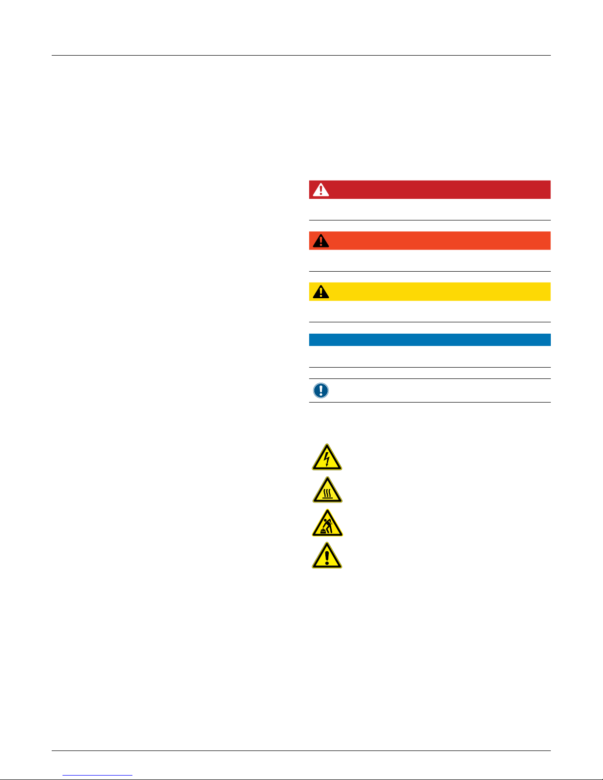
Warning levels
DANGER
Indicates a dangerous situation which, if not avoided, will
always result in death or severe injuries.
WARNING
Indicates a dangerous situation which, if not avoided,
may result in death or severe injuries.
CAUTION
Indicates a dangerous situation which, if not avoided,
may result in slight or moderate injuries.
ATTENTION
Indicates potential material damage that the inverter
may cause to other property.
A Notice contains information on the efcient use of the
inverter or of this manual.
If required, the warning notices are supplemented by warning
symbols indicating the source of the danger.
High voltages or currents
Hot surfaces
Heavy weight
General danger
Page 7
7
Installation and Operating Manual for RPI M15A M20A Solar Inverter V1.0 2016-03-18
1 About this manual
1.4 Writing and identication conventions
Certain contents in this manual are specially identied.
Identication of work instructions
Work instructions that must be carried out in a specic order are
numbered. Numbered work instructions must always be carried
out in the specied order.
1. First work step
→ If required, the result of the work step is described here.
This serves as a check that the work step has been
performed correctly.
2. Second work step
3. Third work step
If a work instruction consists of only a single work step or if the
work steps may be carried out in any order, the work steps are
identied as follows:
► Work step
► Work step
Identication of parts of the inverter
Buttons:
ENT
.
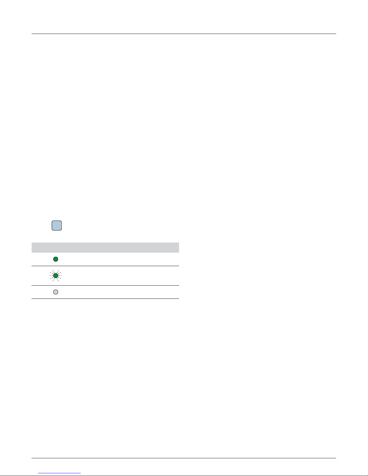
LEDs: A
lArm LED
LED Meaning
LED is permanently lit.
LED is ashing.
LED is off.
Identication of information shown on the display
Names of menus or menu entries: User settings
Names of parameters: Cos phi
Page 8
2 Basic safety instructions
Installation and Operating Manual for RPI M15A M20A Solar Inverter V1.0 2016-03-18
8
2. Basic safety instructions
● In order to meet the safety requirements of IEC 62109-5.3.3
and to avoid personal injury and material damage, the in-
verter must be installed and operated in accordance with the
safety instructions and work instructions in this manual. Delta
Energy Systems is not liable for damage arising from noncompliance with the safety instructions and work instructions
in this manual.
● The inverter may only be installed and commissioned by
tters who are trained and approved in the installation and
commissioning of grid-connected solar inverters.
● All repairs to the inverter must be carried out by Delta Energy
Systems. Otherwise the guarantee will be void.
● Warning notices and warning symbols that have been at-
tached to the inverter by Delta Energy Systems must not be
removed.
● The inverter has a high leakage current. The grounding cable
must be connected before putting the inverter into operation.
● Do not disconnect any cables when the inverter is under
load, as there is a risk of arcing.
● To prevent damage caused by lightning strikes, observe the
regulations that are applicable in your country.
● The surface of the inverter can become very hot in operation.
Do not touch any part of the inverter except for the display
unless you are wearing safety gloves.
● The inverter is very heavy. The inverter must be lifted and
carried by at least two people.
● Only SELV-compliant (EN 60950) devices may be connected
to the RS485 ports.
● To ensure protection class IP65, all connections must be
adequately sealed. Unused connectors must be sealed with
cover caps.
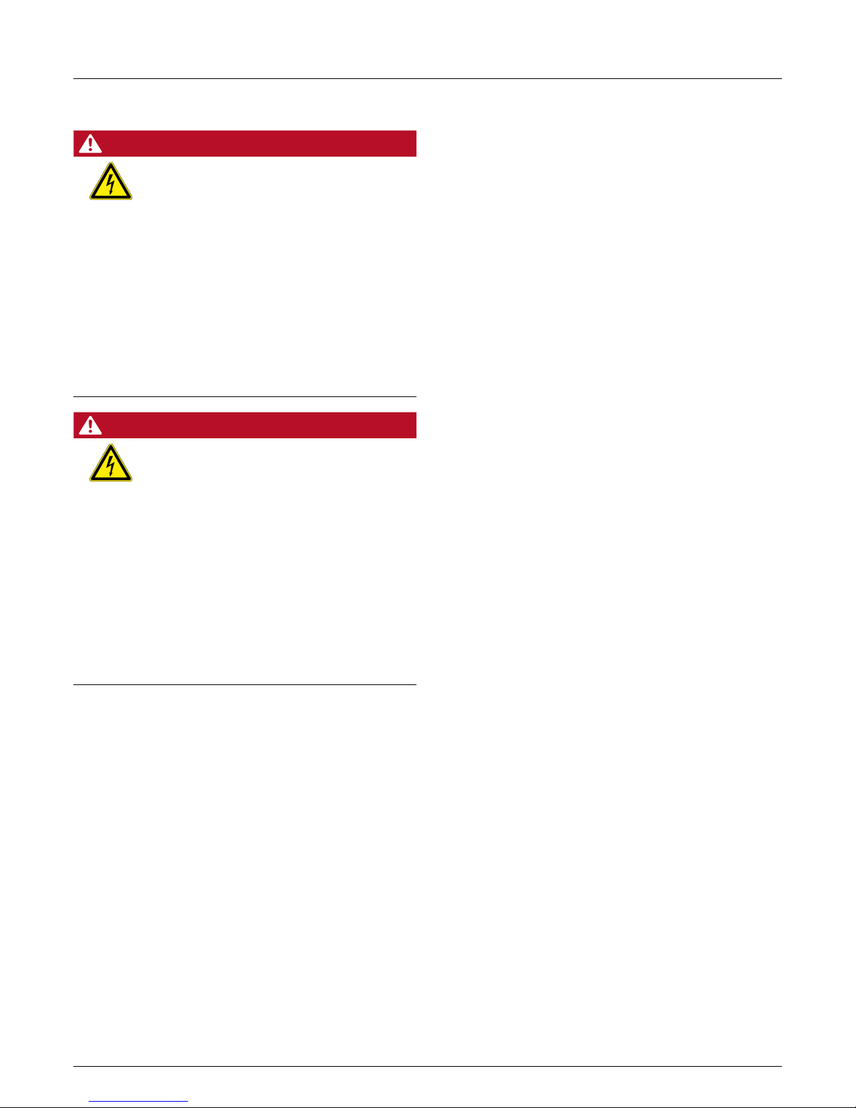
DANGER
Electric shock
During operation there is a potentially lethal voltage present inside the inverter. Even after the
inverter has been disconnected from all power
sources, this voltage is present in the inverter for
up to a further 80 seconds.
Therefore always perform the following work
steps before working on the inverter
1. Turn the DC disconnector to the OFF posi-
tion.
2. Disconnect the inverter from all AC and DC
sources and make sure that none of the connections can be inadvertently re-established.
3. Wait at least 80 seconds to allow the internal
capacitors to discharge.
DANGER
Electric shock
There is a potentially lethal voltage present
on the DC terminals of the inverter. The solar
modules start to produce current as soon as light
falls on them. This occurs even if the light is not
falling directly on the solar modules.
► Never disconnect the inverter from the solar
modules when it is under load.
► Turn the DC disconnector to the OFF posi-
tion.
► Disconnect the connection to the grid so that
the inverter cannot supply any energy to it.
► Disconnect the inverter from all AC and DC
sources. Make sure that none of the connections can be inadvertently re-established.
► Protect the DC cables from being inadvert-
ently touched.
Page 9

9
Installation and Operating Manual for RPI M15A M20A Solar Inverter V1.0 2016-03-18
3 Intended use
3. Intended use
The inverter may only be used for its intended purpose.
The intended use of the inverter is dened as follows:
● Use in static solar installations that are connected to the
public power grid, to convert the direct current generated
by the solar modules in the solar installation into alternating
current which is fed into the public power grid.
● Use in compliance with the power values and ambient
conditions stipulated by the manufacturer.
The following uses are considered to be not as intended:
● Use in isolated “island” operation, i.e., with no connection to
the public power grid. The inverter has functions to prevent
island operation.
● Use in mobile solar installations
Page 10
3 Intended use
Installation and Operating Manual for RPI M15A M20A Solar Inverter V1.0 2016-03-18
10
Deschap RPI M15A M20A EC_Decl EN 20151.doc
EC Declaration of Conformity
Producer: Delta Energy Systems (Germany) GmbH
Address: Tscheulinstr. 21, 79331 Teningen, Germany
Product
Description: Solar Inverter for Grid operation
Model:
RPI-M15A, RPI-M20A
The product described above in the form as delivered is in conformity with the provisions of
the following European Directives:
2004/108/EC Council Directive on the approximation of the laws of the Member States relating
to electromagnetic compatibility
EN 61000-6-3:2007+A1:2011 / EN 61000-6-4:2007+A1:2011
EN 61000-3-11:2000 / EN 61000-3-12:2005
EN 61000-6-2:2005 / EN 61000-6-1:2007
EN 61000-4-2:2009 /EN 61000-4-3:2010
EN 61000-4-4:2012 /EN 61000-4-5:2006
EN 61000-4-6:2009
EN 61000-4-8:2010
EN 61000-4-11:2004
2006/95/EC Council Directive on the approximation of the laws of the Member States related
to electrical equipment designed for use within certain voltage limits
IEC 62109-1:2010, IEC 62109-2:2011
Teningen, Jan 16th 2015
Patrick Schahl Andreas Hoischen
Product
Management
LOB SPE
Head of LOB
SPE
Name, Fu nction
Signature
Name, Fu nction
This declaration certifies the conformity to the specified directives but contains no assurance of properties. The
safety documentation accompanying the product shall be considered in detail.
Page 11
11
Installation and Operating Manual for RPI M15A M20A Solar Inverter V1.0 2016-03-18
4 Product overview
4. Product overview
4.1 Scope of delivery
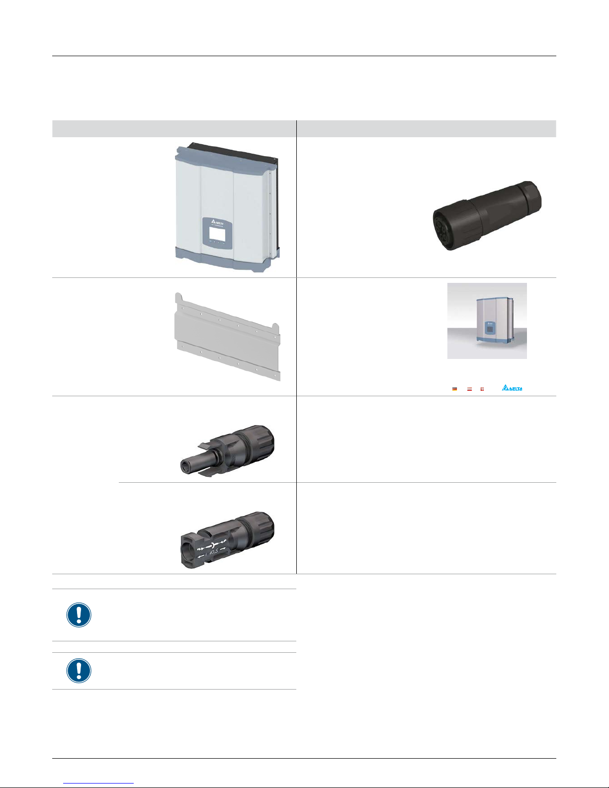
Part Quantity Picture/Description Part Quantity Picture/Description
Inverter 1
AC plug 1
Amphenol C16-3
Mounting plate 1
Installation
quick start and
basic safety
instructions
1
Installationsk urz anleitung
RPI M15A
RPI M20A
Deutschland Ö sterreich Schweiz
DC plugs
4
Multi-contact MC4 for DC+ for
4/6 mm
2
(32.0017P0001-UR)
4
Multi-contact MC4 for DC– for
4/6 mm
2
(32.0016P0001-UR)
Before starting the installation work, check the
delivery for completeness and all components for
damage.
Do not use any damaged components.
Keep the packaging.
Page 12
4 Product overview
Installation and Operating Manual for RPI M15A M20A Solar Inverter V1.0 2016-03-18
12
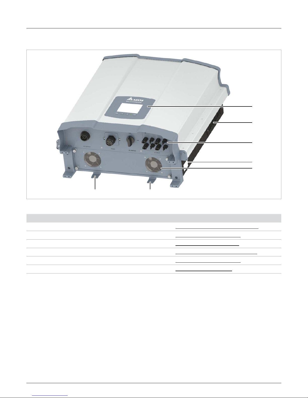
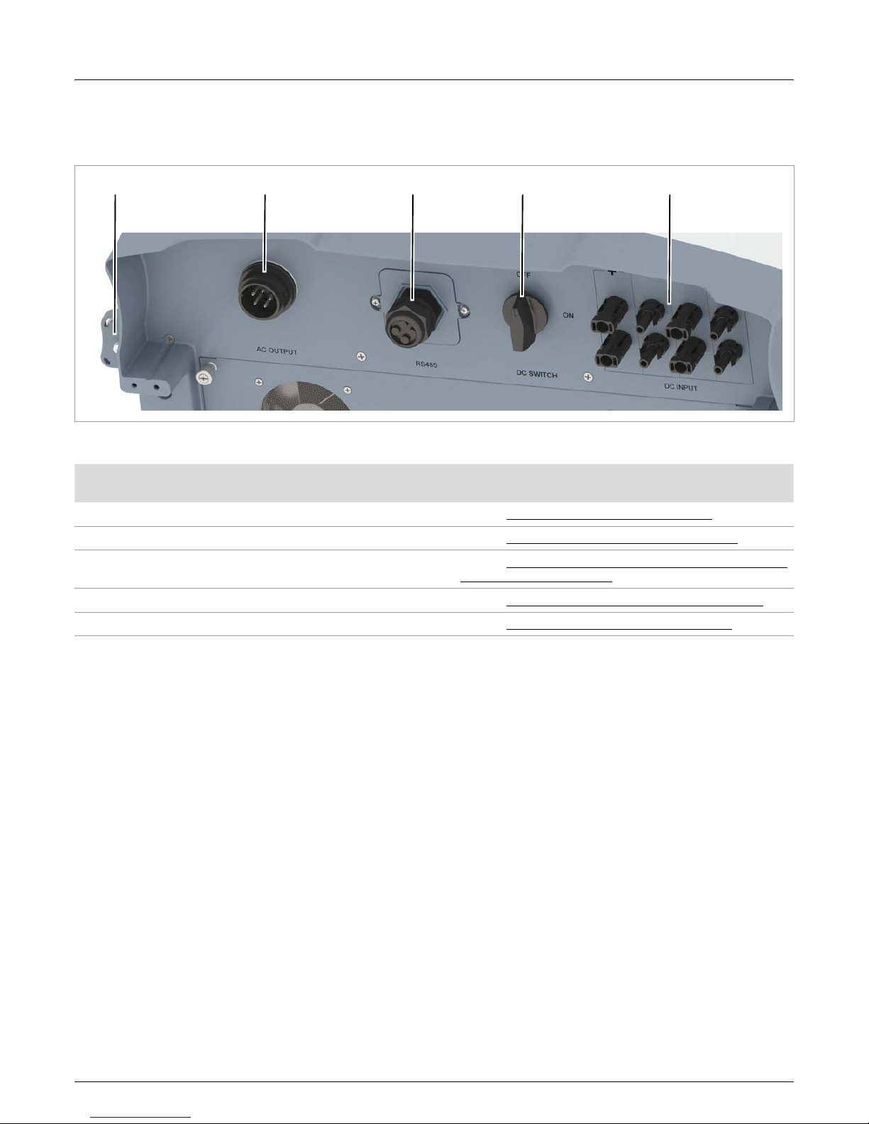
4.2 Overview of components and connections
1
2
3
4
5
6 6
Fig. 4.1: Overview of components and connections
Component/Connection Description
1 Display, buttons, status LEDs
Refer to “4.3 Display, buttons, status LEDs”, page 13
2 Air outlets
Refer to “4.5 Fans and air outlets”, page 17
3 Electrical terminals
Refer to “4.4 Electrical terminals”, page 14
4 Type plate
Refer to “4.7 Information on the type plate”, page 19
5 Fan
Refer to “4.5 Fans and air outlets”, page 17
6 Mounting holes
Refer to “4.6 Mounting holes”, page 18
Page 13
13
Installation and Operating Manual for RPI M15A M20A Solar Inverter V1.0 2016-03-18
4 Product overview
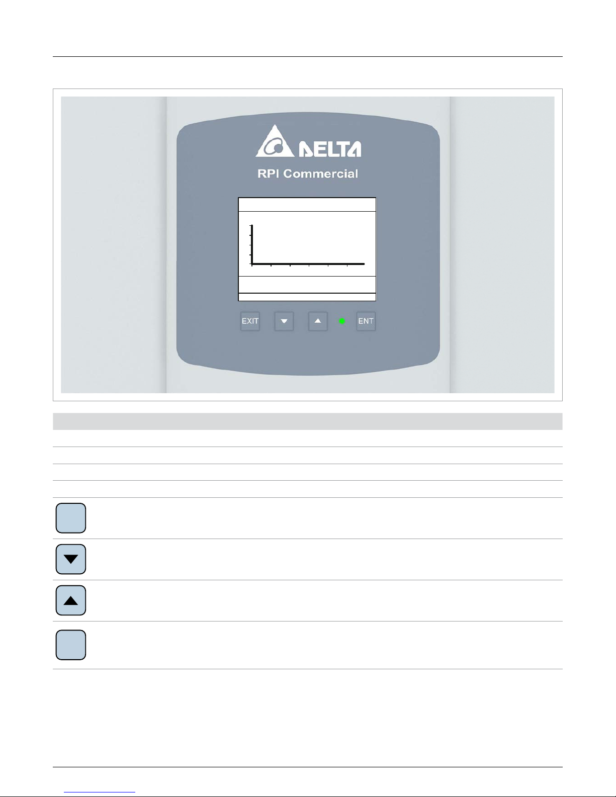
4.3 Display, buttons, status LEDs
20
15
10
5
0
4 8 12 16 20 24
kW 2013.06.21
kWh
kWh kg
2013.06.21
Stunde
E-Stunde:
E-Tag: Ersparnis CO2:
Beenden
Jahr
21. Jun 2013 09:30
Ertrag - Tag
Component Description Use
LEDs
S
tAtuS Multi-coloured LED; indicates the current operating status.
Buttons
EX IT
Exit
Exit the current menu.
Cancel the setting of a parameter. Changes are not adopted.
Down
Move down through the menu.
Reduce the value of a settable parameter.
Up
Move up through the menu.
Increase the value of a settable parameter.
ENT
Enter
Select a menu entry.
Open a settable parameter for editing.
Finalize the setting of a parameter. Changes are adopted.
Page 14
4 Product overview
Installation and Operating Manual for RPI M15A M20A Solar Inverter V1.0 2016-03-18
14
4.4 Electrical terminals
4.4.1 Overview
1 2 3 4 5
Fig. 4.2: Overview of the electrical terminals
Component/Connection Identication on the
inverter
Description
1 Grounding connection
Refer to “4.4.2 Grounding connection”, page 15
2 AC terminal AC OUTPUT
Refer to “4.4.3 AC terminal (AC OUTPUT)”, page 15
3
Connector for RS485, dry contacts and
digital inputs
RS485
Refer to “4.4.4 Terminal for RS485, dry contacts and external
power off (RS485)”, page 16
4 DC disconnector DC SWITCH
Refer to “4.4.5 DC disconnector (DC SWITCH)”, page 16
5 DC terminals DC INPUT
Refer to “4.4.6 DC terminals (DC INPUT)”, page 17
Page 15
15
Installation and Operating Manual for RPI M15A M20A Solar Inverter V1.0 2016-03-18
4 Product overview
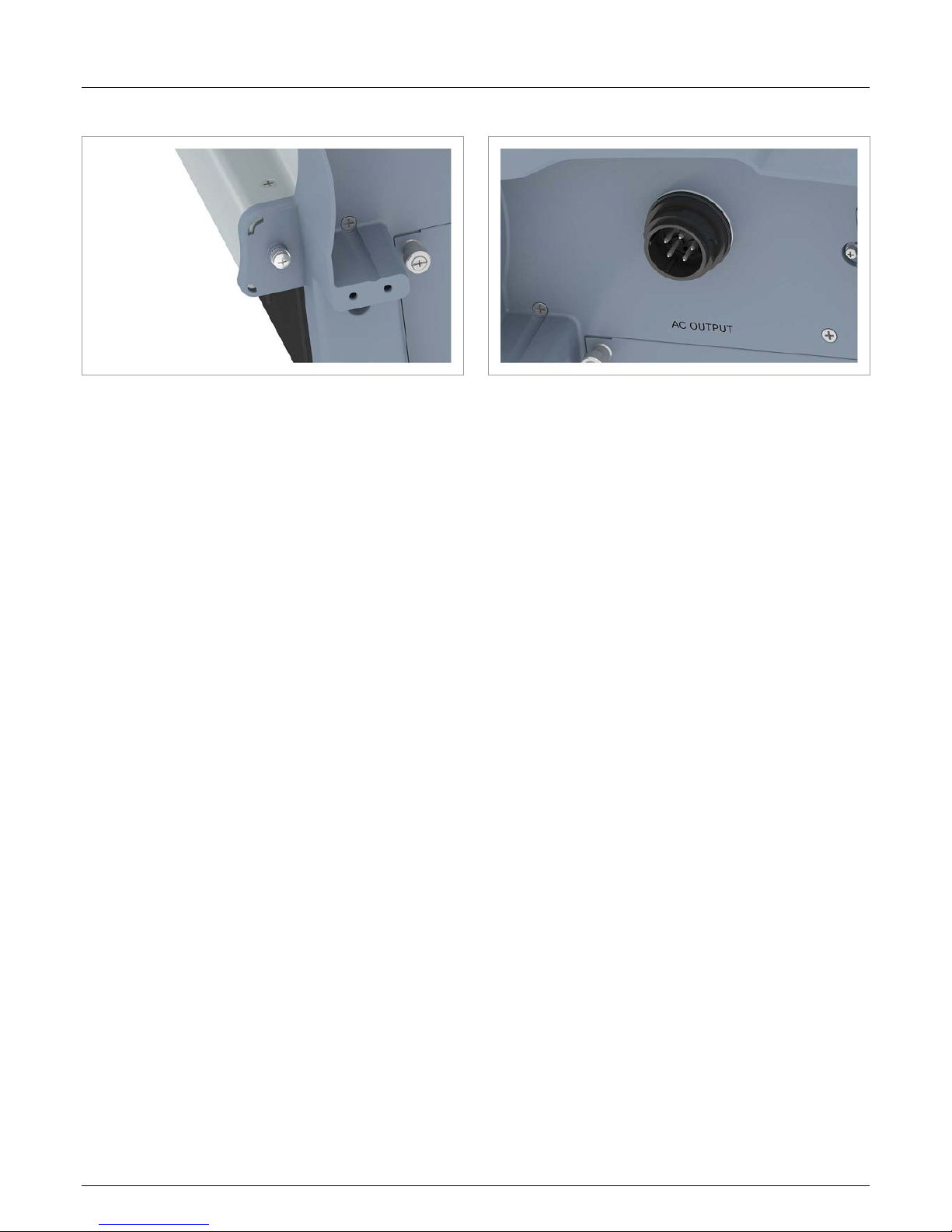
4.4.2 Grounding connection
Fig. 4.3: Position of the grounding connection on the inverter
The inverter housing can be grounded by means of the grounding connection.
M4 screw, spring washer, at washer and serrated washer are
tted to the inverter.
4.4.3 AC terminal (AC OUTPUT)
Fig. 4.4: Position of the AC terminal on the inverter
The inverter is connected to the public grid by means of the AC
terminal.
Purpose:
● To supply alternating current to the public grid.
● To supply power to the display when no supply voltage is
available from the solar modules.
Usable grid types
● Grids with 3 phases and a neutral conductor: 3P4W
(L1, L2, L3, N, PE)
● Grids with 3 phases, no neutral conductor: 3P3W
(L1, L2, L3, PE).
Required plug type:
Amphenol C16-3 (C016 20E004 800 2)
The AC plug is included in the delivery.
Page 16
4 Product overview
Installation and Operating Manual for RPI M15A M20A Solar Inverter V1.0 2016-03-18
16
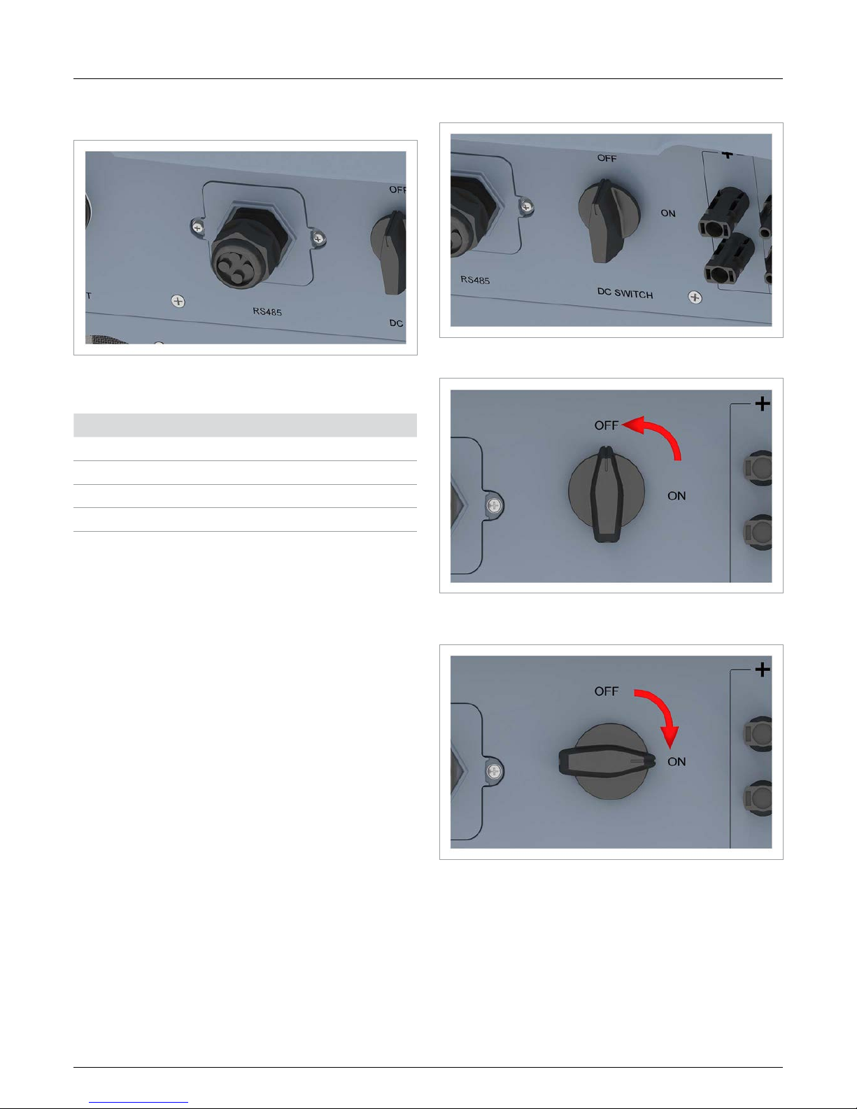
4.4.4 Terminal for RS485, dry contacts and external power off (RS485)
Fig. 4.5: Position of the RS485 connector on the inverter
Available connections:
Connection Connection type
2x RS485 (DATA+ and DATA–) Terminal block
1x VCC (12 V, 0.5 A) Terminal block
1x dry contacts Terminal block
1x external power off (EPO) RJ45
4.4.5 DC disconnector (DC SWITCH)
Fig. 4.6: Position of the DC disconnector on the inverter
The inverter is disconnected from the solar modules when the
DC disconnector is in the OFF position.
The inverter is connected to the solar modules when the DC
disconnector is in the ON position.
Page 17
17
Installation and Operating Manual for RPI M15A M20A Solar Inverter V1.0 2016-03-18
4 Product overview
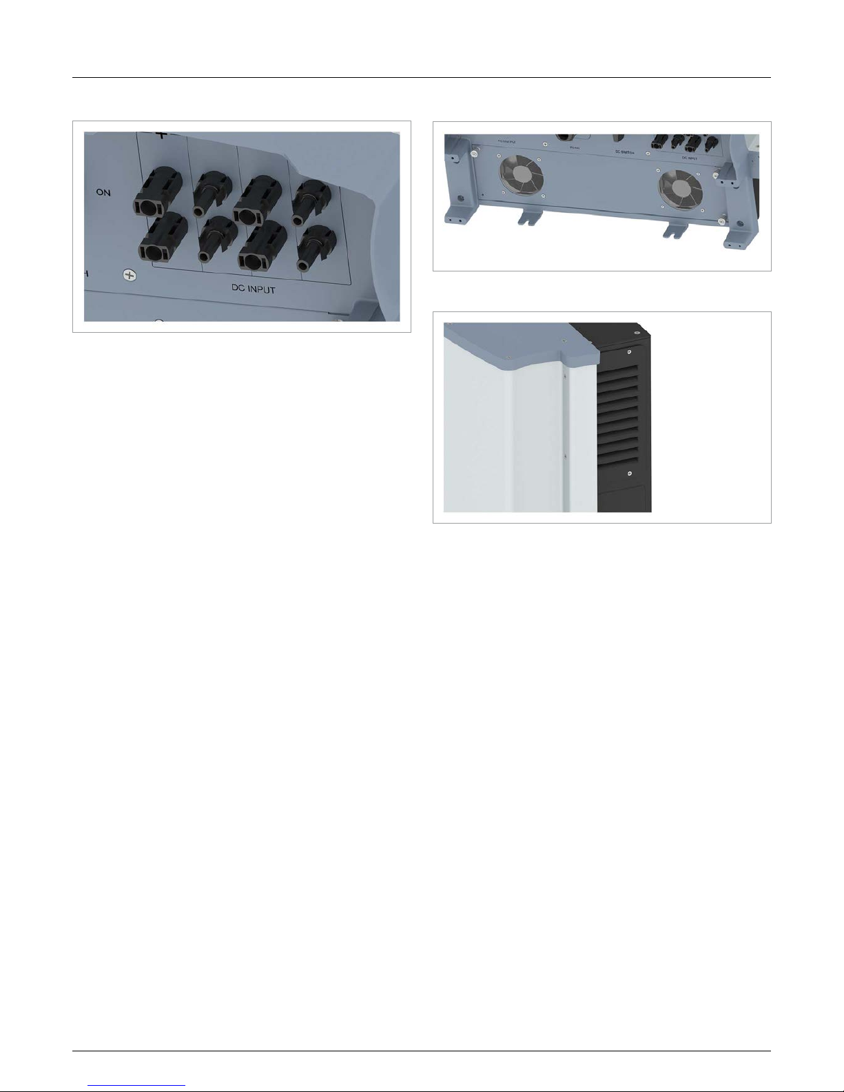
4.4.6 DC terminals (DC INPUT)
Fig. 4.7: Position of the DC terminals on the inverter
The solar modules are connected to the DC terminals.
Required plug type:
● Multi-contact MC4 32.0017P0001-UR for DC+
● Multi-contact MC4 32.0016P0001-UR for DC–
4 pairs of DC plugs are included in the delivery.
4.5 Fans and air outlets
Fig. 4.8: Position of the fans on the inverter
Fig. 4.9: Position of the air outlets on the inverter
Ambient air is drawn in by the fans and fed through the inverter
for cooling. The warmed air is returned to the environment via the
air outlets.
Page 18
4 Product overview
Installation and Operating Manual for RPI M15A M20A Solar Inverter V1.0 2016-03-18
18
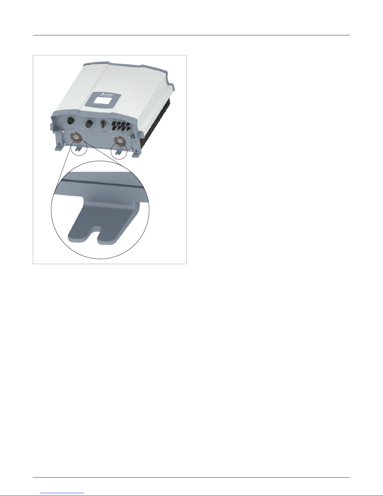
4.6 Mounting holes
Fig. 4.10: Position of the mounting holes on the inverter
The mounting holes are used to bolt the inverter to the wall or to
the mounting system.
The mounting holes are a t for M6 bolts.
Page 19
19
Installation and Operating Manual for RPI M15A M20A Solar Inverter V1.0 2016-03-18
4 Product overview
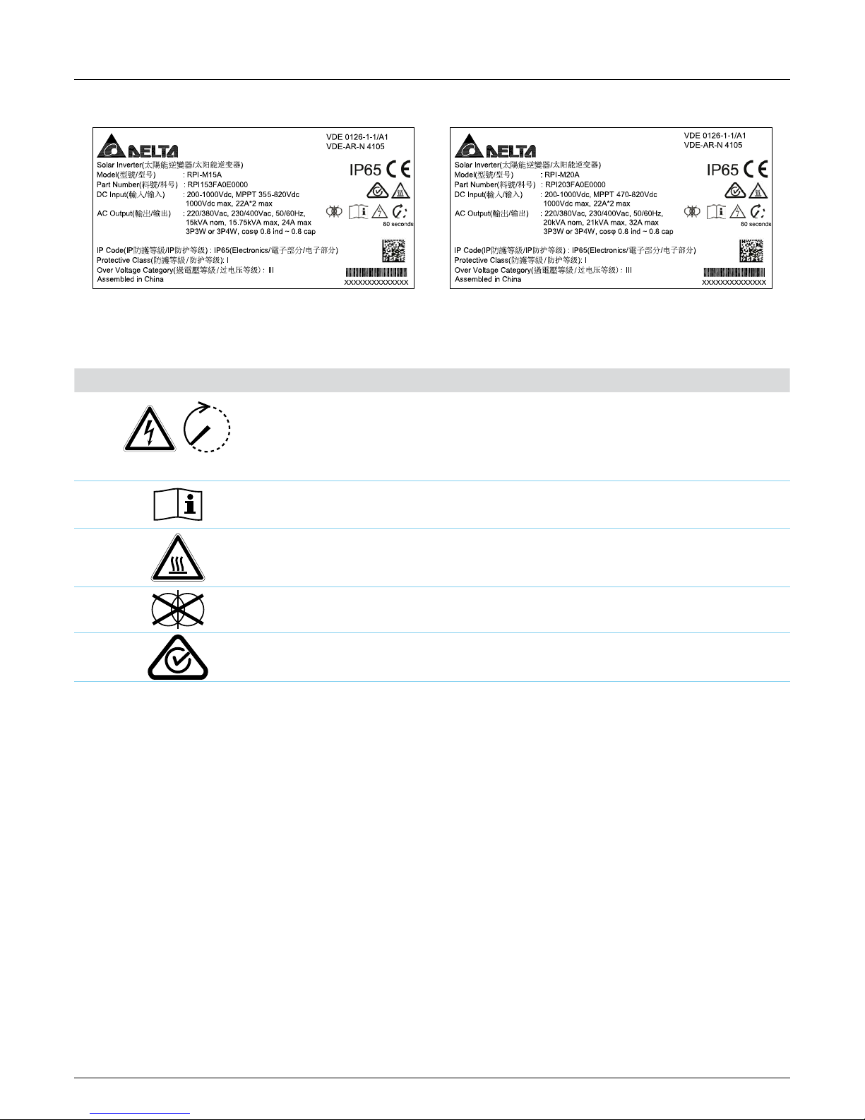
4.7 Information on the type plate
Fig. 4.11: M15A type plate Fig. 4.12: M20A type plate
Symbols on the type plate
Symbol Description
80 seconds
Potentially lethal electric shock
When the inverter is in operation, there is a potentially lethal voltage inside which persists for a
further 80 seconds after the power supply is disconnected.
Never open the inverter housing. The inverter does not contain any parts that can be serviced or
repaired by the operator or the tter. Opening the inverter housing will invalidate the guarantee.
Before starting any work on the inverter, read the supplied manual and follow the instructions
contained therein.
Hot surfaces.
The inverter housing can become very hot during operation.
The inverter does not contain a transformer.
The inverter meets the Australian standard for electrical safety and the EMC standard. Applies
only to Australia and New Zealand.
Page 20
4 Product overview
Installation and Operating Manual for RPI M15A M20A Solar Inverter V1.0 2016-03-18
20
Information on the type plate
M15A M20A
Solar inverter Solar inverter This is a solar inverter.
Model: RPI M15A Model: RPI M20A Delta model name
Part number: RPI802FA0E1000 Part number: RPI103FA0E1000 Delta part number
DC input DC input
200-1000Vdc 200-1000Vdc DC input voltage range
MPPT 355-820Vdc MPPT 470-820Vdc
MPP input voltage range at full power (with symmetrically congured DC inputs)
1000Vdc max 1000Vdc Maximum DC input voltage
22A*2 max 22A*2 max Maximum DC input current (22 A on each of DC1 and DC2)
AC Output AC output
220/380, 230/400 Vac 220/380, 230/400 Vac Nominal AC voltage
50/60 Hz 50/60 Hz Nominal AC frequency
15kVA nom 20kVA nom Nominal reactive power
15.75kVA max 21kVA max Maximum reactive power
24A max 32A max Maximum AC current
3P3W or 3P4W 3P3W or 3P4W
The inverter can be connected to 3-phase grids with no neutral
conductor (3P3W, 3 phases + PE) and 3-phase grids with a neutral conductor (3P4W, 3 phases + N + PE).
cosφ 0.8ind~0.8cap cosφ 0.8ind~0.8cap Setting range of the cos φ displacement factor
IP Code: IP65 (Electronics) IP Code: IP65 (Electronics) Protection class for the internal electronics according to EN 60529
Protective Class: I Protective Class: I Protection class according to EN 61140
Overvoltage Category: III Overvoltage Category: III Overvoltage category according to IEC 62109-1
Assembled in China Assembled in China Made in China
VDE 0126-1-1/A1 VDE 0126-1-1/A1 The inverter meets the requirements of VDE 0126-1-1/A1.
VDE-AR-N 4105 VDE-AR-N 4105 The inverter meets the requirements of VDE-AR-N 4105.
IP65 IP65 Protection class IP65
CE marking. With this marking, Delta declares that the inverter
meets the stipulations of the applicable EU directives.
Page 21

21
Installation and Operating Manual for RPI M15A M20A Solar Inverter V1.0 2016-03-18
5 Operating behaviour
5. Operating behaviour
5.1 General mode of operation
The inverter converts the direct current generated by the solar
modules into alternating current which is then fed into the public
grid.
5.2 MPP tracking
MPP tracking is an automatic function which continuously
ensures that the inverter is always operating in the maximum
output range possible under the current ambient conditions. The
DC input voltage is used as the reference for this.
The inverter has 2 MPP trackers, one for each of DC1 and DC2.
The solar modules that are connected to the two DC inputs do
not need to have the same output. Within certain limits, module
strings with differing outputs can be connected (see “14. Technical data” page 162).
5.3 Anti-islanding device
In the event of a grid failure, the integrated anti-islanding device
shuts the inverter down.
5.4 Temperature control
The specic values for the technical parameters described in
this section can be found in the chapter “14. Technical data”
page 162.
The inverter has two operating temperature ranges that are
important for its operating behaviour.
● Operating temperature range
● Operating temperature range without limiting
The operating temperature range is greater than the operating
temperature range without limiting.
If the ambient temperature lies within the operating temperature
range without limiting, the inverter works at the maximum possible output power. If the ambient temperature is higher, but still
within the operating temperature range, the output power will be
continually reduced with rising ambient temperature. If the ambient temperature rises above the operating temperature range,
the AC output will be switched off and the inverter will no longer
feed energy into the public grid.
The inverter is cooled by means of fans.
5.5 Inuence of DC input voltage
The specic values for the technical parameters described in
this section can be found in the chapter “14. Technical data”
page 162.
The maximum DC input voltage must never be exceeded. Measure the DC input voltage and use an overvoltage protector on the
DC side to prevent higher DC input voltages. The maximum open
circuit voltage occurs at the lowest ambient temperatures that
can be assumed.
The DC input voltage range is used to dene the DC input voltages for which the inverter will supply power to the public grid.
The MPP input voltage range is used to dene the DC input voltages for which the MPP trackers are activated.
The MPP input voltage range at full power is used to dene the
DC input voltages for which the inverter can deliver the maximum
output power. However the actual output power still depends on
other conditions such as, for example, the ambient temperature.
5.6 Functions for inuencing the operating
behaviour
The inverter provides various functions which can be used to
inuence the operating behaviour.
● Active power control
● Reactive power control
● Insulation and grounding monitoring
A detailed description of these functions can be found in the
chapter “9. Settings” page 72.
5.7 Power grid imbalance compensation
The inverter has an integrated power grid imbalance compensator. This ensures that the supplied power is always distributed
evenly across all the phases.
Page 22
6 Planning the installation
Installation and Operating Manual for RPI M15A M20A Solar Inverter V1.0 2016-03-18
22
6. Planning the installation
This chapter is intended only as an aid to planning the installation work. The implementation
of the installation work and the associated dangers are described in the chapter “Installation”.
6.1 Installation location
Fig. 6.1: Installation location – condition of the wall
► The inverter is very heavy. The wall must be able to bear the
heavy weight of the inverter.
► Always use the mounting plate that is supplied with the
inverter.
► Use mounting materials (wall plugs, screws, etc.) that are
suitable for the wall or the mounting system as well as the
heavy weight of the inverter.
► To prevent malfunctions, mount the inverter on a vibration-
free wall.
► When the inverter is used in residential areas or in buildings
with animals, possible noise emissions may cause a disturbance. Therefore take care when choosing the mounting
location.
► Mount the inverter on a re-resistant wall.
✔
✘ ✘
?
?
?
?
Fig. 6.2: Mounting location – installation height
► Mount the inverter so that the information on the display can
be read without difculty and the buttons can be operated.
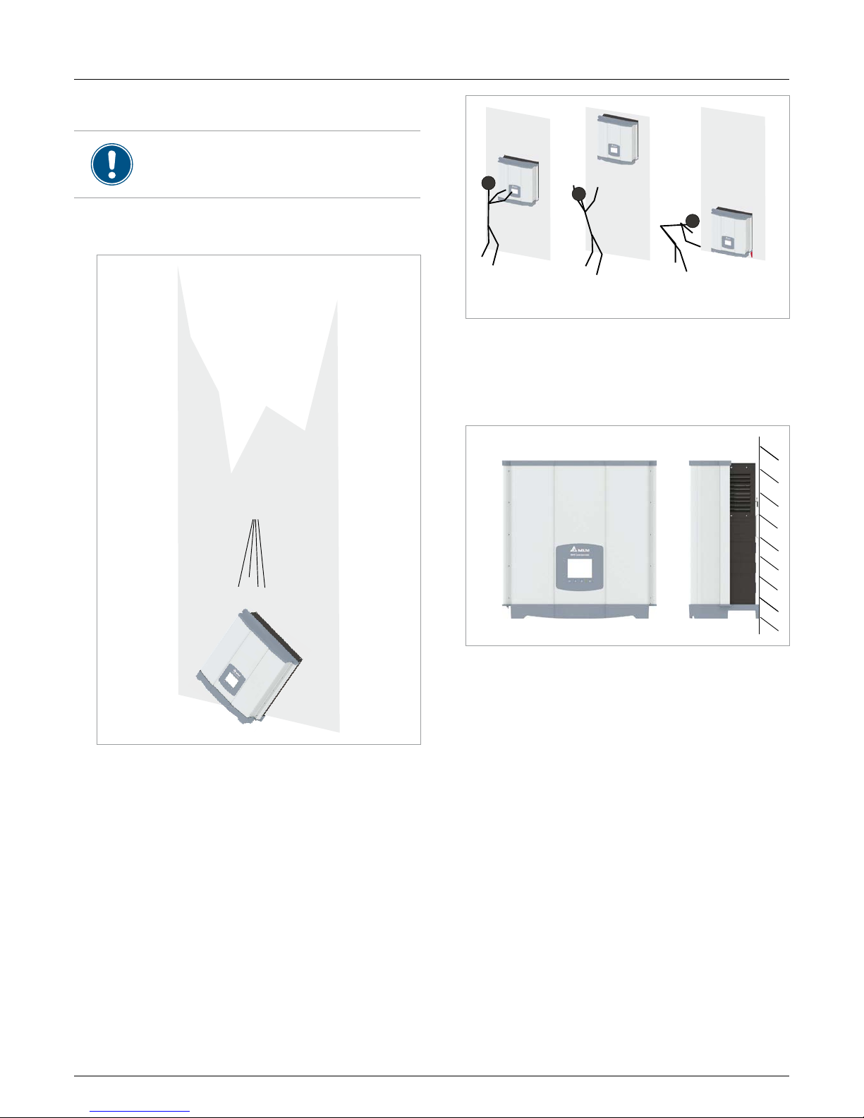
6.2 Mounting position
Fig. 6.3: Mounting position
► Mount the inverter vertically.
Page 23
23
Installation and Operating Manual for RPI M15A M20A Solar Inverter V1.0 2016-03-18
6 Planning the installation
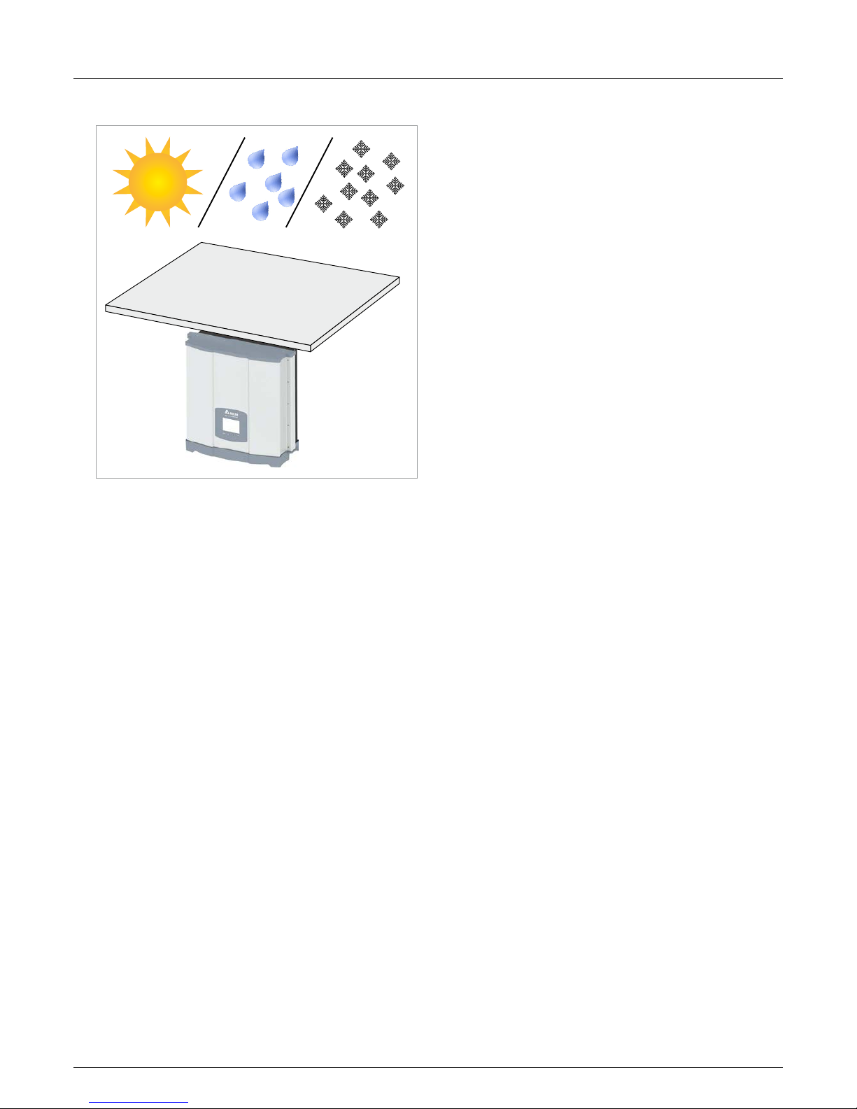
6.3 Outside installations
Fig. 6.4: Outside installations
► The inverter is classied IP65 and can be installed inside and
outside. Nevertheless, the inverter should be protected from
direct solar irradiation, rain and snow by means of a roof. If,
for example, the inverter becomes too hot as a result of solar
irradiation, the output will be reduced. This is normal operating behaviour for the inverter and is necessary to protect the
internal electronics.
Page 24
6 Planning the installation
Installation and Operating Manual for RPI M15A M20A Solar Inverter V1.0 2016-03-18
24
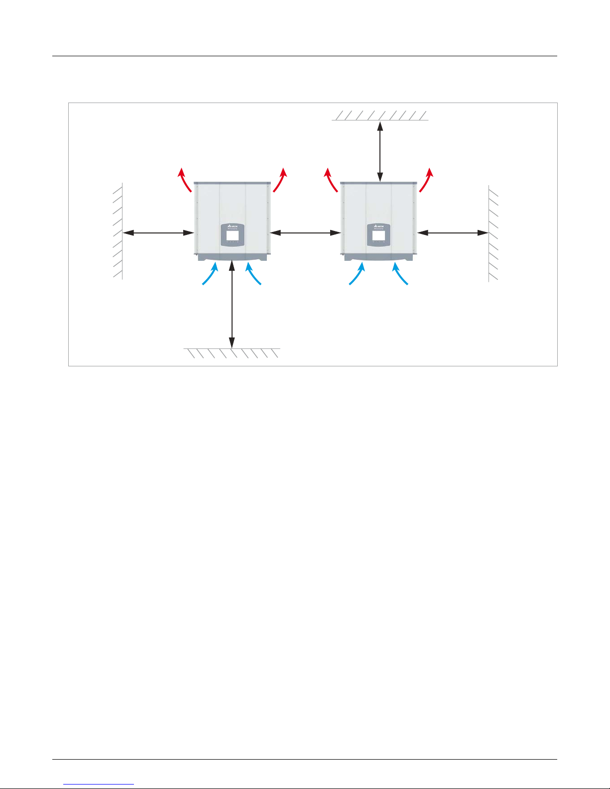
6.4 Environmental conditions and air circulation
^
>30 cm >30 cm
>50 cm
>20 cm
>30 cm
Fig. 6.1: Mounting clearances and air circulation
► Ensure adequate air circulation. Warm air must be able
to escape upwards. Leave sufcient space around each
inverter.
► Do not install inverters directly one above another as this
might cause mutual heating.
► Take note of the operating temperature range without limit-
ing and the operating temperature range. If the operating
temperature range without limiting is exceeded, the inverter
limits the AC power that is fed into the grid. If the operating
temperature range is exceeded, the inverter stops supplying
the grid. This is normal operating behaviour for the inverter
and is necessary to protect the internal electronics.
► In areas with many trees or meadows, pollen can block the
air inlets and outlets and impede the air ow.
Page 25
25
Installation and Operating Manual for RPI M15A M20A Solar Inverter V1.0 2016-03-18
6 Planning the installation
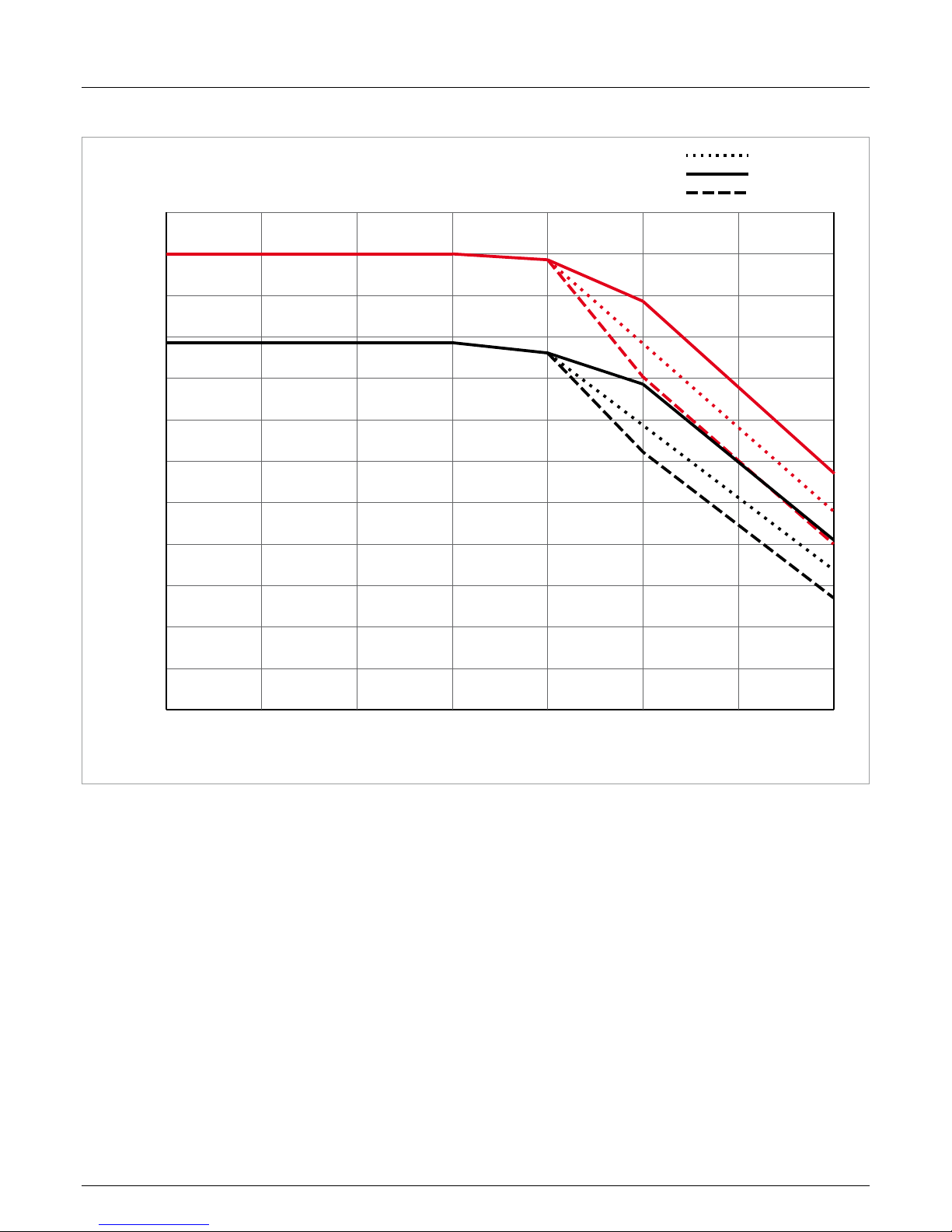
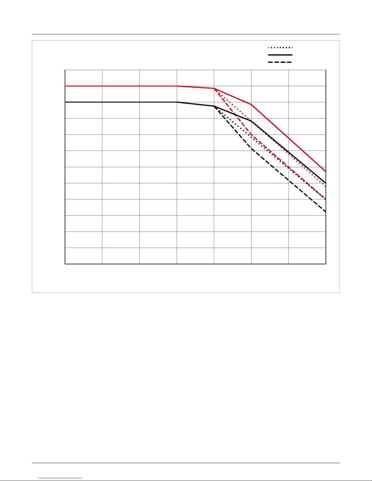
6.5 Characteristics
0.70
0.75
0.50
0.55
0.60
0.65
0.80
0.85
0.90
0.95
1.00
1.05
1.10
3025 35 40 45 50 55 60
P/Pn cos φ 0.9
820 V
DC
635 V
DC
355 V
DC
Ambient temperature [ °C]
Fig. 6.2: M15A characteristic “Power limiting as a function of ambient temperature, cos φ = 0.90”
Page 26

6 Planning the installation
Installation and Operating Manual for RPI M15A M20A Solar Inverter V1.0 2016-03-18
26
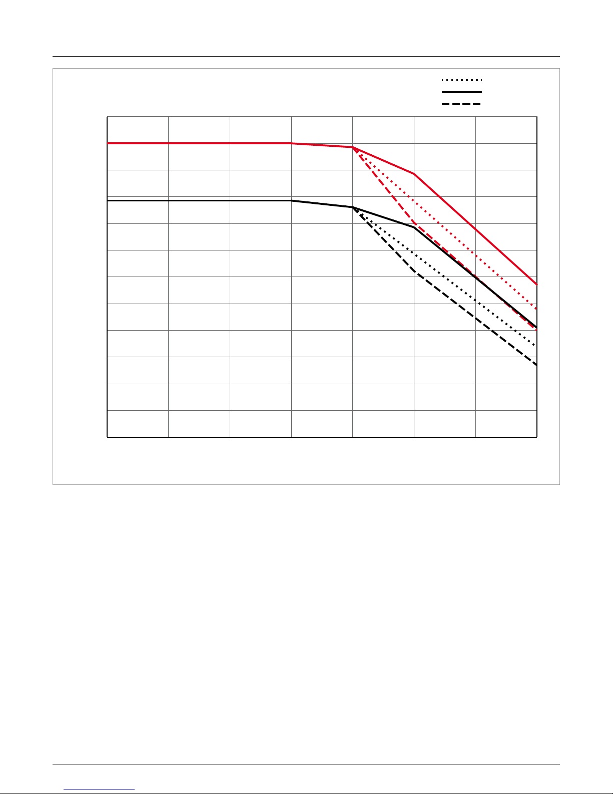
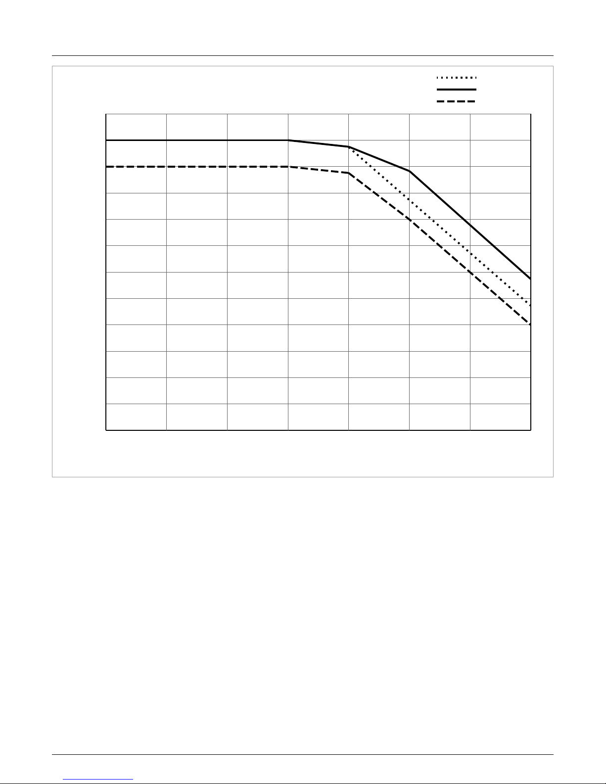
0.70
0.75
0.50
0.55
0.60
0.65
0.80
0.85
0.90
0.95
1.00
1.05
1.10
3025 35 40 45 50 55 60
P/Pn cos φ 0.95
820 V
DC
635 V
DC
355 V
DC
Ambient temperature [ °C]
Fig. 6.3: M15A characteristic “Power limiting as a function of ambient temperature, cos φ = 0.95"
Page 27

27
Installation and Operating Manual for RPI M15A M20A Solar Inverter V1.0 2016-03-18
6 Planning the installation
0.70
0.75
0.50
0.55
0.60
0.65
0.80
0.85
0.90
0.95
1.00
1.05
1.10
3025 35 40 45 50 55 60
P/Pn cos φ 1.00
820 V
DC
635 V
DC
355 V
DC
Ambient temperature [ °C]
Fig. 6.4: M15A characteristic “Power limiting as a function of ambient temperature, cos φ = 1.0
Page 28
6 Planning the installation
Installation and Operating Manual for RPI M15A M20A Solar Inverter V1.0 2016-03-18
28
0.70
0.75
0.50
0.55
0.60
0.65
0.80
0.85
0.90
0.95
1.00
1.05
1.10
3025 35 40 45 50 55 60
P/Pn cos φ 0.9
820 V
DC
635 V
DC
470 V
DC
Ambient temperature [ °C]
Fig. 6.5: M20A characteristic “Power limiting as a function of ambient temperature, cos φ = 0.90”
Page 29
29
Installation and Operating Manual for RPI M15A M20A Solar Inverter V1.0 2016-03-18
6 Planning the installation
0.70
0.75
0.50
0.55
0.60
0.65
0.80
0.85
0.90
0.95
1.00
1.05
1.10
3025 35 40 45 50 55 60
P/Pn cos φ 0.95
820 V
DC
635 V
DC
470 V
DC
Ambient temperature [ °C]
Fig. 6.6: M20A characteristic “Power limiting as a function of ambient temperature, cos φ = 0.95"
Page 30
6 Planning the installation
Installation and Operating Manual for RPI M15A M20A Solar Inverter V1.0 2016-03-18
30
0.70
0.75
0.50
0.55
0.60
0.65
0.80
0.85
0.90
0.95
1.00
1.05
1.10
3025 35 40 45 50 55 60
P/Pn cos φ 1.00
820 V
DC
635 V
DC
470 V
DC
Ambient temperature [ °C]
Fig. 6.7: M20A characteristic “Power limiting as a function of ambient temperature, cos φ = 1.0
Page 31

31
Installation and Operating Manual for RPI M15A M20A Solar Inverter V1.0 2016-03-18
6 Planning the installation
6.6 Dimensions
107
460
172,8
158,7
31
30
25
82
3
14
192,8
97,8 3030
129°
Fig. 6.8: Dimensions of mounting plate (in mm)
612 278
625
437
Fig. 6.9: Dimensions of inverter (in mm)
Page 32

6 Planning the installation
Installation and Operating Manual for RPI M15A M20A Solar Inverter V1.0 2016-03-18
32
6.7 AC connection (grid)
► Always comply with the specic regulations that apply in your
country or region.
► Always comply with the specic regulations of your energy
provider.
► Install all the prescribed safety and protective devices (for
example, automatic circuit breakers and/or overvoltage protection devices).
► Protect the inverter with a suitable upstream contact breaker:
Model Upstream contact breaker
RPI M15A 30 A
RPI M20A 40 A
G N L1 L3L2
N
L1
L2
L3
PE
to the
inverter
Fig. 6.10: Position of the upstream contact breaker
Residual current device
Because of its design, the inverter cannot feed any DC residual
current into the grid. The inverter thus meets the requirements of
DIN VDE 0100-712.
Possible fault events have been investigated by Delta in compliance with the currently applicable installation standards. The
investigations have shown that no dangers arise if the inverter is
operated in combination with an upstream residual current device
(RCD), Type A. The use of a residual current device, Type B, is
not necessary.
Minimum tripping current of a residual current
device, Type A
≥100 mA
The tripping current required by the residual current device depends primarily on the quality of
the solar modules, the size of the PV installation
and the ambient conditions (e.g. humidity). However the tripping current must not be lower than
the specied minimum tripping current.
Integrated residual current monitoring unit
The integrated residual current monitoring unit (RCMU) is certi-
ed in accordance with VDE 0126 1-1/A1:2012-02 §6.6.2.
Permissible grounding systems
Grounding system TN-S TN-C TN-C-S TT IT
Permissible Ye s Yes Yes Yes No
Requirements for the grid voltage
3P3W Voltage range 3P4W Voltage range
L1-L2 400 V
AC
± 20% L1-N 230 VAC ± 20%
L1-L3 400 V
AC
± 20% L2-N 230 VAC ± 20%
L2-L3 400 V
AC
± 20% L3-N 230 VAC ± 20%
Page 33

33
Installation and Operating Manual for RPI M15A M20A Solar Inverter V1.0 2016-03-18
6 Planning the installation
6.8 DC connection
NOTE
Incorrectly dimensioned solar installation.
An incorrectly dimensioned solar installation can
cause damage to the inverter.
► When calculating the number of solar
modules, always take heed of the inverter’s
technical specications (input voltage range,
maximum current and maximum input
power).
NOTE
Overheating of the DC terminals.
Exceeding the maximum current can cause over-
heating of the DC terminals and lead to a re.
► Always take into account the maximum cur-
rent through the DC terminals when planning
the installation.
6.8.1 Symmetric and asymmetric conguration
of the DC inputs
The inverter has an MPP tracker for each DC input (DC 1 and
DC 2).
The two MPP trackers work independently of one another; the
optimum operating point is thus set separately for DC 1 and DC 2
For this reason, the module strings on DC 1 and DC 2 can have
different alignments or dimensioning. A classic application example is a building with a gable roof on which the roofs face east
and west.
Variant 1: Symmetric conguration of the DC inputs
The total input power is always evenly distributed (50%/50%)
between DC 1 and DC 2.
Variant 2: Asymmetric conguration of the DC inputs
The maximum permitted total input power can be distributed
between DC 1 and DC 2 in the range 67%/33% to 33%/67%.
Thus, for example, a distribution of 60%/40% or 45%/55% is
possible.
The percentages always refer to the instantaneous value of the
input power. Consequently for an east-west roof installation it
is possible to install 67% of the maximum input power on both
roofs. It is then possible to exploit the effect that the solar modules on the two roofs reach their maximum at different times of
the day.
7:00 13:00 19:00
kW
Total
East Roof
West Roof
East
West
Fig. 6.11: Design concept of a system with 2 MPP trackers with
asymmetric loading of the DC inputs
Page 34

6 Planning the installation
Installation and Operating Manual for RPI M15A M20A Solar Inverter V1.0 2016-03-18
34
Symmetric conguration
I
max
U
max
U
startup
Input Current
Input Voltage
Max. Power MPPT Range
Input Current DC 1
Input Current DC 2
Asymmetric conguration
I
max
U
max
U
startup
Input Current
Input Voltage
Max. Power MPPT Range
Input Current DC 1
Input Current DC 2
Fig. 6.12: I-V characteristics for symmetric and asymmetric
conguration of the DC inputs (illustration of principle)
For currents and voltages, refer to “14. Technical
data”, page 162.
6.8.2 Separate and parallel connected DC inputs
The inverter can be used with separately or parallel connected
DC inputs.
Separately connected DC inputs
DC wiring
PV array
Fig. 6.13: Separately connected DC inputs
In this case the module strings for DC 1 are connected separately from those for DC 2. MPP tracker 1 controls the module
strings on DC 1 and MPP tracker 2 controls the module strings
on DC 2.
This way, symmetrically and asymmetrically congured DC inputs
can be implemented.
This variant of the DC cabling cannot be used for solar modules
that are grounded.
Page 35

35
Installation and Operating Manual for RPI M15A M20A Solar Inverter V1.0 2016-03-18
6 Planning the installation
Parallel-connected DC inputs
+
–
DC wiring
PV array
Distribution box
Fig. 6.14: Parallel-connected DC inputs
The module strings are brought together in a distribution box
and then the DC cables are connected to DC 1 and DC 2. MPP
tracker 1 controls all the module strings; MPP tracker 2 is not
used.
This way, only symmetrically congured DC inputs can be implemented.
This variant of the DC cabling is mandatory for solar modules
that are grounded.
Page 36

6 Planning the installation
Installation and Operating Manual for RPI M15A M20A Solar Inverter V1.0 2016-03-18
36
6.8.3 Connecting to ungrounded solar modules
When solar modules that are not grounded are used, the DC
inputs can be connected separately or in parallel.
3P4W 3P3W
1 - L1
2 - L2
3 - L3
4 - N
5 - PE
1 - L1
2 - L2
3 - L3
- PE
Separate or
parallel DC inputs
AC wiring
DC wiring
PV array
Fig. 6.15: System design when using solar modules that are
not grounded
Page 37

37
Installation and Operating Manual for RPI M15A M20A Solar Inverter V1.0 2016-03-18
6 Planning the installation
6.8.4 Connecting to grounded solar modules
When grounded solar modules are used, the DC inputs must be connected in parallel.
There must be an isolating transformer connected between the connection to the grid and the AC terminal on the inverter.
After commissioning, the insulation monitoring on the inverter display must be set, see “9.12 Insulation mode and insulation resistance”,
page 94.
1 - L1
2 - L2
3 - L3
4 - N
5 - PE
1 - L1
2 - L2
3 - L3
- PE
3P4W 3P3W
+
–
Z
Z
parallel DC inputs
ONLY
Distribution Box
DC wiring
PV array
Positive grounding
Negative grounding
OR
Utility
3-phase, 230/400 V
AC
star or delta connection
Inverter
230/400 V
AC
Isolated
transformer
Isolated
transformer
Fig. 6.16: System design when using grounded solar modules
Page 38

6 Planning the installation
Installation and Operating Manual for RPI M15A M20A Solar Inverter V1.0 2016-03-18
38
6.8.5 Connecting the DC strings to the DC inputs
Check the polarity of the DC voltage before connecting the solar modules to the inverter.
The negative terminals of the solar modules must be connected to DC–, the positive terminals to DC+.
The connection schemes shown in the following can also be mixed.
+
–
OFF
ON
–
+
+
–
OFF
ON
–
+
Fig. 6.17: Connecting one string to a DC connection
+
–
+
–
OFF
ON
+
–
2
+
–
OFF
ON
2
+
–
+
–
Fig. 6.18: Connecting two strings to a DC connection
+
–
+
–
+
–
OFF
ON
+
–
1 2
+
–
+
–
+
–
+
–
OFF
ON
12
Fig. 6.19: Connecting three strings to a DC connection
1 Always take account of the maximum reverse current
loading capability of the solar modules when selecting
protective devices (for example fuses).
2 Always take account of the local safety regulations when
selecting protective devices.
Page 39

39
Installation and Operating Manual for RPI M15A M20A Solar Inverter V1.0 2016-03-18
6 Planning the installation
6.9 Connecting to a data logger
The inverter can be connected to a data logger via RS485, for
example to monitor the PV installation or to change the settings
on the inverter.
Several inverters can be connected in series to a data logger.
The following recommendations must be taken into consideration
for a stable data link.
Connecting a single inverter to a data logger
► Switch on the RS485 termination resistor.
► Run the RS485 cable at a distance from the other cables to
prevent interference to the data link.
Connecting several inverters to a data logger
► Switch on the RS485 termination resistor on the last inverter
in the chain.
► If the data logger has no internal RS485 termination resis-
tor, then switch on the RS485 termination resistor on the rst
inverter in the chain as well.
► Switch off the RS485 termination resistor on all the other
inverters.
► A different inverter ID must be set on each inverter. Other-
wise the data logger will not be able to identify the individual
inverters.
► Set the same baud rate for RS485 on each inverter.
► Run the RS485 cable at a distance from the other cables to
prevent interference to the data link.
Requirements for the cables
● Twisted and shielded cable
● Cable diameter: 5 mm
● Wire cross-section: 1 mm
2
6.10 Dry contacts
An external audible or visual alarm device can be connected to
the dry contacts on the inverter.
COM N01
Fig. 6.20: Pin assignment of the dry contacts
If the fans fail, COM and N01 will be closed.
Requirements for the cables
● Twisted and shielded cables (CAT5 or CAT6) with 2 cores
● Cable diameter: 5 mm
● Wire cross-section: 1 mm
2
6.11 Connecting a ripple control receiver
Please contact Delta customer service if you want to connect a
ripple control receiver. You will nd the contact data on the last
page of this document.
6.12 Using an external grid and system protection device
For PV installations larger than 30 kVA, the German standard
VDE-AR-N 4105, Section 6.1 requires the use of an external grid
and installation protection device with section switch.
Alternatively, VDE-AR-N 4105, Section 6.4.1 allows the use of an
inverter with an internal section switch if the switch disconnects
the inverter from the grid in less than 100 ms.
This inverter meets the requirements of VDE-AR-N 4105, Section
6.4.1 if the following rmware is installed: DSP ≥ 2.20 / COMM
≥ 2.32. In this case, no external grid and installation protection
device is needed.
Page 40

6 Planning the installation
Installation and Operating Manual for RPI M15A M20A Solar Inverter V1.0 2016-03-18
40
6.13 Connecting a PC to the inverter
The inverter settings can be changed with the aid of a PC. The
following accessories will be required for this.
Accessory Description
USB-RS485 adapter with
RS485 cable
To connect a PC to the inverter
Delta Service Software
To change the settings on the
inverter
USB-RS485-Adapter and Delta Service Software are available
from Delta. Please contact Delta customer service in your own
country. You will nd the contact data on the last page of this
document.
Page 41

41
Installation and Operating Manual for RPI M15A M20A Solar Inverter V1.0 2016-03-18
6 Planning the installation
6.14 What you need
Only tools and materials that are not included in the delivery are
listed in this section.
6.14.1 To assemble the inverter
Part Quantity Description
Mounting bolts 6 to 12
The mounting plate must be fastened with 6 to 12 M6 bolts.
Depending on where the inverter is to be mounted (e.g. brick wall, concrete
wall, metal frame, etc.), additional mounting aids will be needed: wall plugs,
washers, serrated washers, nuts, etc.
Always take note of the conditions at the installation location when selecting
the mounting materials.
Galvanic corrosion may occur when mounting material consisting of differing
metals is used.
6.14.2 To connect the inverter to the grid (AC)
Part Quantity Description
AC cable -
The AC plug supplied with the inverter has the following technical features:
Plug type
Amphenol C16-3
(C016 20E004 800 2)
Rated current 40 A
Min. / max. cable diameter 11 / 20 mm
Min. / max. wire cross-section 2.5 / 6 mm
2
Recommended torque for clamping screws ≥ 0.7 Nm
The AC plug can only be used with exible copper cable.
When calculating the cable cross-section, take the following inuencing fac-
tors into account:
● Cable material
● Temperature conditions
● Cable length
● Installation type
● Voltage drop
● Power losses in the cable
Always comply with the installation regulations that are applicable in your
country.
France: Comply with the installation regulations of UTE 15-712-1. This
standard includes regulations concerning minimum cable cross-sections and
about preventing overheating caused by high currents.
Germany: Comply with the installation regulations of VDE 0100-712. This
standard includes regulations concerning minimum cable cross-sections and
about preventing overheating caused by high currents.
Australia/New Zealand: Comply with the installation regulations of AS/NZS
5033:2005. This standard includes regulations concerning minimum cable
cross-sections and about preventing overheating caused by high currents.
Page 42

6 Planning the installation
Installation and Operating Manual for RPI M15A M20A Solar Inverter V1.0 2016-03-18
42
Part Quantity Description
Wire end ferrules 4 - 5
Ferrules must be used on the wire ends of the AC cable to ensure that there
is adequate electrical contact between the AC plug and the AC cable.
Use crimping pliers to attach the ferrules to the wires.
6.14.3 To connect the inverter to the solar modules
Part Quantity Description
DC plugs 4 pairs
The required number of DC plugs is supplied with the inverter. Should you
need a different size or a replacement, order the required version using the
following table. Available from Multi-Contact.
DC cable - Cable cross-section must match the supplied DC plugs.
a
b
DC terminals on the inverter DC plugs for DC cable
a b
Multi-Contact
mm
2
mm
DC–
^
1.5 / 2.5
3-6 32.0010P0001-UR
5.5-9 32.0012P0001-UR
4 / 6
3–6 32.0014P0001-UR
5.5-9 32.0016P0001-UR
1)
DC+
1.5 / 2.5
3-6 32.0011P0001-UR
5.5-9 32.0013P0001-UR
4 / 6
3-6 32.0015P0001-UR
5.5-9 32.0017P0001-UR
1)
1)
Supplied with the inverter
Page 43

43
Installation and Operating Manual for RPI M15A M20A Solar Inverter V1.0 2016-03-18
6 Planning the installation
Part Quantity Description
DC protective caps Up to 8
To secure the DC plugs so that they can only be removed from the DC terminals with the DC open end spanner. Available from Multi-Contact.
Comply with the local regulations concerning the use of the DC protective
caps.
France: The DC protective caps must be used.
DC open end spanner 1
Open end spanner for disconnecting the DC plugs and the protective caps
from the DC terminals. Available from Multi-Contact.
6.14.4 To ground the inverter housing
Part Quantity Description
Grounding cable with terminal lug 1
Typically a yellow-green copper cable with a cross-section of at least 6 mm
2
.
M4 screw, spring washer, at washer and serrated washer are already tted
to the inverter.
Always comply with the local regulations regarding the requirements for the
grounding cable.
6.14.5 To wire up the RS485 and the dry contacts
Part Quantity Description
Cable -
Twisted and shielded cable (CAT5 or CAT6) with a cable diameter of 5 mm
and a wire cross-section of 1 mm
2
.
SOLIVIA Gateway M1 G2 1
For connecting to SOLIVIA Monitor, the internet-based monitoring system
from Delta.
Page 44

6 Planning the installation
Installation and Operating Manual for RPI M15A M20A Solar Inverter V1.0 2016-03-18
44
6.14.6 To connect a PC
Part Quantity Description
USB-RS485 adapter 1
To connect a PC to the inverter. Available from Delta
2-core conductor 1 Bell wire. Both ends open.
Delta Service Software 1 To change the settings on the inverter. Available from Delta
6.14.7 Other parts
Part Quantity Description
Warning labels -
Comply with the local regulations concerning the attachment of warning
labels.
Do not work on this equipment until it is located
from both mains and on site generation supplies.
WARNING
Dual supply
Isolate on-site Generation Unit(s) at _ _ _ _ _ _ _ _ _ _ _ _ _ _ _ _ _ _ _ _ _ _ _ _ _ _ _ _ _ _ _ _ _ _ _ _
Isolate mains supply at _ _ _ _ _ _ _ _ _ _ _ _ _ _ _ _ _ _ _ _ _ _ _ _ _ _ _ _ _ _ _ _ _ _ _ _ _ _ _ _ _ _ _ _ _
Warning - Only persons authoriz ed by DNO may remove the main cut out fuse
Warning
Two voltage sources present
- Distribution network
- PV modules
Disconnect both sources
before carrying out any work
Page 45

45
Installation and Operating Manual for RPI M15A M20A Solar Inverter V1.0 2016-03-18
7 Installation
7. Installation
► Read the chapter “1. Planning the installa-
tion”, page 1 and this chapter through
completely before starting work on the installation.
7.1 Safety information
DANGER
Electric shock
During operation there is a potentially lethal voltage present inside the inverter. Even after the
inverter has been disconnected from all power
sources, this voltage is present in the inverter for
up to a further 80 seconds.
Therefore always perform the following work
steps before working on the inverter
1. Turn the DC disconnector to the OFF posi-
tion.
2. Disconnect the inverter from all AC and DC
sources and make sure that none of the connections can be inadvertently re-established.
3. Wait at least 80 seconds to allow the internal
capacitors to discharge.
DANGER
Electric shock
There is a potentially lethal voltage present
on the DC terminals of the inverter. The solar
modules start to produce current as soon as light
falls on them. This occurs even if the light is not
shining directly on the solar modules.
► Never disconnect the inverter from the solar
modules when it is under load.
► Turn the DC disconnector to the OFF posi-
tion.
► Disconnect the connection to the grid so that
the inverter cannot supply any energy to it.
► Disconnect the inverter from all AC and DC
sources. Make sure that none of the connections can be inadvertently re-established.
► Protect the DC cables from being inadvert-
ently touched.
WARNING
Heavy weight
The inverter is very heavy.
► The inverter must be lifted and carried by at
least 2 people or with suitable lifting gear.
NOTE
Water ingress.
► All sealing caps that were removed during the
installation should be kept for future use (e.g.
transport or storage).
► Never open the inverter housing! Otherwise
the guarantee will be void.
7.2 Sequence of installation steps
The connections for RS485, the dry contacts and
the external power off (EPO) are all located on
the communications card. These installation tasks
can therefore be combined.
Recommended sequence of installation steps:
1. Installing the inverter
2. Grounding the inverter housing
3. Connecting the communications card
1)
4. Connecting the dry contacts and the external power off
(optional)
5. Connecting the grid (AC)
6. Connecting the solar modules (DC)
Page 46

7 Installation
Installation and Operating Manual for RPI M15A M20A Solar Inverter V1.0 2016-03-18
46
2. Fit the inverter into the mounting plate.
3. Check that the inverter is hanging correctly in the mounting
plate.
7.3 Installing the inverter
WARNING
Heavy weight
The inverter is very heavy.
► The inverter must be lifted and carried by at
least 2 people or with suitable lifting gear.
1. Fasten the mounting plate to the wall or to the mounting
system using 6 to 12 M6 screws.
Page 47

47
Installation and Operating Manual for RPI M15A M20A Solar Inverter V1.0 2016-03-18
7 Installation
4. Check that the lower edge of the inverter is resting correctly
against the wall or mounting system.
Page 48

7 Installation
Installation and Operating Manual for RPI M15A M20A Solar Inverter V1.0 2016-03-18
48
5. Fasten the inverter to the wall or mounting system.
Page 49

49
Installation and Operating Manual for RPI M15A M20A Solar Inverter V1.0 2016-03-18
7 Installation
7.4 Grounding the inverter housing
WARNING
High current
► Always comply with the local regulations
regarding the requirements for the grounding
cable.
► Even if there are no local regulations, the
inverter housing should always be grounded
to increase safety.
► Always ground the inverter housing before
connecting the inverter to the grid and the
solar modules.
1. Bolt the grounding cable to the inverter. M4 screw, spring
washer, at washer and serrated washer are already tted to
the inverter.
1
2
3
4
5
1 Serrated washer
2 Grounding cable with terminal lug
3 Flat washer
4 Spring washer
5 M4 bolt
2. Perform a continuity test of the grounding connection. If the
connection is not adequately conductive, scrape away the
paint from the inverter housing under the serrated washer to
achieve a better electrical contact.
Page 50

7 Installation
Installation and Operating Manual for RPI M15A M20A Solar Inverter V1.0 2016-03-18
50
1 VCC (+12 V; 0.5 A)
2 GND
3 DATA+ (RS485)
4 DATA– (RS485)
5 DATA+ (RS485)
6 DATA– (RS485)
Terminal pair 3/4 or 5/6 may be used. The second terminal pair is
only needed if several inverters are connected with one another
via RS485.
Data format
Baud rate 9600, 19200, 38400; Default: 19200
Data bits 8
Stop bit 1
Parity n/a
After commissioning, the baud rate can be set on the inverter
display, see “9.8 Baud rate for RS485”, page 86.
DIP switch for RS485 termination resistor
Fig. 7.3: DIP switch for RS485 termination resistor
Connection to a Delta SOLIVIA Gateway M1 G2
Individual wires are connected at the inverter end; an RJ45 plug
is used at the Gateway end.
Inverter SOLIVIA Gateway M1 G2
1
8
DATA + Terminal 3 or 5 Pin 7
DATA – Terminal 4 or 6 Pin 6 or 8
7.5 Connecting a data logger via RS485
The connections for RS485, the dry contacts and
the external power off (EPO) are all located on
the communications card. These installation tasks
can therefore be combined.
NOTE
Water ingress.
► All sealing caps that were removed during the
installation should be kept for future use (e.g.
transport or storage).
7.5.1 Introduction
3
1
2
4
Fig. 7.1: Components on the communications card
1 DIP switch for RS485 termination resistor
2 RS485 (terminal block)
3 Dry contacts (terminal block)
4 External power off (RJ45)
Terminal assignment of the RS485 terminal block
Fig. 7.2: Terminal assignment of the RS485 terminal block
Page 51

51
Installation and Operating Manual for RPI M15A M20A Solar Inverter V1.0 2016-03-18
7 Installation
Connection diagram for an individual inverter
ON
1
RS485
Termination resistor = ON
Data logger
Fig. 7.4: Connection diagram: Single inverter to data logger
Connection diagram for several inverters
► If the data logger has no integrated RS485 termination resis-
tor, then switch on the RS485 termination resistor on the rst
inverter.
► After commissioning, set a different inverter ID on each
inverter, see “9.9 Inverter ID”, page 88.
...
ON
1
ON
1
ON
1
RS485
Termination resistor = ON Termination resistor = OFF Termination resistor = OFF
Data logger
Fig. 7.5: Connection diagram: Several inverters to data logger
Page 52

7 Installation
Installation and Operating Manual for RPI M15A M20A Solar Inverter V1.0 2016-03-18
52
7.5.2 Wiring a single inverter
1.
Twist off the cable gland from the communications connector
and remove the gland and seal.
2. Remove the cover screws and then the cover.
3. Withdraw the communications card.
4. Pull the cable through the cable gland and seal.
Do not remove the rubber plugs from the unused leadthroughs in the seal.
5. Connect the wire for DATA+ to terminal 5 and the wire for
DATA– to terminal 6.
Page 53

53
Installation and Operating Manual for RPI M15A M20A Solar Inverter V1.0 2016-03-18
7 Installation
6. Set the DIP switch for the RS485 termination resistor to the
ON position.
7. Insert the communications card.
8. Fit the cover and tighten the screws.
9. Fit the seal and cable gland and tighten the cable gland.
Page 54

7 Installation
Installation and Operating Manual for RPI M15A M20A Solar Inverter V1.0 2016-03-18
54
7.5.3 Wiring several inverters
...
Data logger
1. On the rst inverter: Twist off the cable gland from the com-
munications connector and remove the gland and seal.
2. Remove the cover screws and then the cover.
3. Withdraw the communications card.
4. Pull the cable coming from the data logger and the cable go-
ing to the second inverter through the gland and the seal.
Do not remove the rubber plugs from the unused leadthroughs in the seal.
5. On the cable coming from the data logger: Connect the wire
for DATA+ to terminal 5 and the wire for DATA– to terminal 6.
On the cable going to the next inverter: Connect the wire for
DATA+ to terminal 3 and the wire for DATA– to terminal 4.
Page 55

55
Installation and Operating Manual for RPI M15A M20A Solar Inverter V1.0 2016-03-18
7 Installation
6. Set the DIP switch for the RS485 termination resistor to the
OFF position.
7. Insert the communications card.
8. Fit the cover and tighten the screws.
9. Fit the seal and cable gland and tighten the cable gland.
Page 56

7 Installation
Installation and Operating Manual for RPI M15A M20A Solar Inverter V1.0 2016-03-18
56
...
Data logger
1. On the second and every additional inverter (apart from the
last): Twist off the cable gland from the communications connector and remove the gland and seal.
2. Remove the cover screws and then the cover.
3. Withdraw the communications card.
4. Pull the cable coming from the previous inverter and the ca-
ble going to the next inverter through the gland and the seal.
Do not remove the rubber plugs from the unused leadthroughs in the seal.
5. On the cable coming from the previous inverter: Connect
the wire for DATA+ to terminal 5 and the wire for DATA– to
terminal 6.
On the cable going to the next inverter: Connect the wire for
DATA+ to terminal 3 and the wire for DATA– to terminal 4.
Page 57

57
Installation and Operating Manual for RPI M15A M20A Solar Inverter V1.0 2016-03-18
7 Installation
6. Set the DIP switch for the RS485 termination resistor to the
OFF position.
7. Insert the communications card.
8. Fit the cover and tighten the screws.
9. Fit the seal and cable gland and tighten the cable gland.
Page 58

7 Installation
Installation and Operating Manual for RPI M15A M20A Solar Inverter V1.0 2016-03-18
58
...
Datenlogger
1. On the last inverter: Twist off the cable gland from the com-
munications connector and remove the gland and seal.
2. Remove the cover screws and then the cover.
3. Withdraw the communications card.
4. Pull the cable coming from the penultimate inverter through
the cable gland and seal.
Do not remove the rubber plugs from the unused leadthroughs in the seal.
Page 59

59
Installation and Operating Manual for RPI M15A M20A Solar Inverter V1.0 2016-03-18
7 Installation
5. Connect the wire for DATA+ to terminal 5 and the wire for
DATA– to terminal 6.
6. Set the DIP switch for the RS485 termination resistor to the
ON position.
7. Insert the communications card.
8. Fit the cover and tighten the screws.
9. Fit the seal and cable gland and tighten the cable gland.
Page 60

7 Installation
Installation and Operating Manual for RPI M15A M20A Solar Inverter V1.0 2016-03-18
60
7.6 Connecting the dry contacts
7.6.1 Introduction
3
1
2
4
Fig. 7.1: Components on the communications card
1 DIP switch for RS485 termination resistor
2 RS485 (terminal block)
3 Dry contacts (terminal block)
4 External power off (RJ45)
7.6.2 Wiring dry contacts with no 12 VDC supply
1.
Twist off the cable gland from the communications connector
and remove the gland and seal.
2. Remove the cover screws and then the cover.
Page 61

61
Installation and Operating Manual for RPI M15A M20A Solar Inverter V1.0 2016-03-18
7 Installation
3. Withdraw the communications card.
4. Pull the cable through the cable gland and seal.
Do not remove the rubber plugs from the unused leadthroughs in the seal.
5. Connect the two wires to COM and N01.
6. Insert the communications card.
7. Fit the cover and tighten the screws.
8. Fit the seal and cable gland and tighten the cable gland.
Page 62

7 Installation
Installation and Operating Manual for RPI M15A M20A Solar Inverter V1.0 2016-03-18
62
2. Remove the cover screws and then the cover.
3. Withdraw the communications card.
4. Pull the cable through the cable gland and seal.
Do not remove the rubber plugs from the unused leadthroughs in the seal.
7.6.3 Wiring dry contacts with an internal 12 VDC
supply
GND
VCC
DATA +
DATA -
DATA +
DATA -
COM
N01
N02
RS485-Klemmenblock
Potenzialfreie
Kontakte
Lampe Summer
Fig. 7.2: Dry contacts with internal 12 VDC supply for external
alarm device, Variant 1
GND
VCC
DATA +
DATA -
DATA +
DATA -
COM
N01
N02
RS485-Klemmenblock
Potenzialfreie
Kontakte
Lampe Summer
Fig. 7.3: Dry contacts with internal 12 VDC supply for external
alarm device, Variant 2
1. Twist off the cable gland from the communications connector
and remove the gland and seal.
Page 63

63
Installation and Operating Manual for RPI M15A M20A Solar Inverter V1.0 2016-03-18
7 Installation
5. Connect the wires according to one of the two variants.
Wiring according to Variant 1 should look like this:
Wiring according to Variant 2 should look like this:
6. Insert the communications card.
7. Fit the cover and tighten the screws.
8. Fit the seal and cable gland and tighten the cable gland.
Page 64

7 Installation
Installation and Operating Manual for RPI M15A M20A Solar Inverter V1.0 2016-03-18
64
7.7 Connecting the external power off
(EPO)
7.7.1 Introduction
3
1
2
4
Fig. 7.1: Components on the communications card
1 DIP switch for RS485 termination resistor
2 RS485 (terminal block)
3 Dry contacts (terminal block)
4 External power off (RJ45)
Pin assignment
Pin Designa-
tion
Short-circuit
Assigned action
1 V1 – –
2 K0 V1 + K0 External power off (EPO)
3 K1 V1 + K1 –
4 K2 V1 + K2 –
5 K3 V1 + K3 –
6 K4 V1 + K4 –
7 K5 V1 + K5 Reserved
8 K6 V1 + K6 Reserved
The relay for the external power off can be set as normally open
or normally closed on the display, see “9.16 External power off
(EPO)”, page 102.
7.7.2 Cabling the external power off
1.
Twist off the cable gland from the communications connector
and remove the gland and seal.
2. Remove the cover screws and then the cover.
Page 65

65
Installation and Operating Manual for RPI M15A M20A Solar Inverter V1.0 2016-03-18
7 Installation
3. Withdraw the communications card.
4. Pull the cable through the cable gland and seal.
Do not remove the rubber plugs from the unused leadthroughs in the seal.
5. Plug the cable connector into the RJ45 socket.
6. Insert the communications card.
7. Fit the cover and tighten the screws.
8. Fit the seal and cable gland and tighten the cable gland.
Page 66

7 Installation
Installation and Operating Manual for RPI M15A M20A Solar Inverter V1.0 2016-03-18
66
7.8 Connecting to the grid (AC)
The inverter can be connected to 3-phase grids
with no neutral conductor (3P3W, 3 phases +
PE) and 3-phase grids with a neutral conductor
(3P4W, 3 phases + N + PE).
► If the inverter is connected to a grid without
neutral conductors, the AC connection type
must be changed to 3P3W on the display
after commissioning, see “9.17 AC connection type”, page 104.
Connecting to 3-phase grids with neutral conductors (3P4W)
L1
L2
PE
N
L3
1 = L1
4 = N
PE
3 = L3
2 = L2
Connecting to 3-phase grids without neutral conductors
(3P3W)
L1
L2
PE
L3
1 = L1
PE
3 = L3
2 = L2
1. Turn the DC disconnector to the OFF position.
Page 67

67
Installation and Operating Manual for RPI M15A M20A Solar Inverter V1.0 2016-03-18
7 Installation
2. Remove the insulation from the cable and the wires. Do not
twist the wire ends as the contact area with the ferrules will
be reduced as a result.
12 mm
52,5 mm
12 mm
55 mm (PE)
3. Push the ferrules on to the wire ends and crimp them.
4. Unscrew the nut and housing from the AC plug.
5. Pull the cable through the nut and the housing.
NOTE
Pay attention to the phase assignment when
connecting the AC cable to the AC plug. Incorrect
wiring can destroy the inverter.
6. Push the wires of the AC cable into the correct pin inserts
and tighten with a screwdriver.
The rst picture shows the wiring for 3-phase grids with neutral conductors (3P4W); the second for 3-phase grids without
neutral conductors (3P3W).
7. Fit the housing and nut and tighten the nut.
Page 68

7 Installation
Installation and Operating Manual for RPI M15A M20A Solar Inverter V1.0 2016-03-18
68
8. Remove the sealing cap from the AC terminal and keep it.
9. Plug the AC plug into the AC terminal on the inverter and
tighten.
10. Secure the AC cable with a strain relief.
11. If the inverter is connected to a grid without neutral conduc-
tors, set the connection type to 3P3W on the display after
commissioning, see “9.17 AC connection type”, page 104.
Page 69

69
Installation and Operating Manual for RPI M15A M20A Solar Inverter V1.0 2016-03-18
7 Installation
7.9 Connecting to the solar modules (DC)
DANGER
Electric shock
There is a potentially lethal voltage present
on the DC terminals of the inverter. The solar
modules start to produce current as soon as light
falls on them. This occurs even if the light is not
shining directly on the solar modules.
► Never disconnect the inverter from the solar
modules when it is under load.
► Turn the DC disconnector to the OFF posi-
tion.
► Disconnect the connection to the grid so that
the inverter cannot supply any energy to it.
► Disconnect the inverter from all AC and DC
sources. Make sure that none of the connections can be inadvertently re-established.
► Protect the DC cables from being inadvert-
ently touched.
Colour of the DC cables
For DC+, use a red cable; for DC–, a black cable.
► Check the polarity with a voltmeter.
Connecting the DC cables
1. Turn the DC disconnector to the OFF position.
2. Remove the sealing caps from the DC terminals and keep
them. Do not remove the sealing caps from unused DC
terminals.
3. Insert the DC plugs with the DC cables into the DC terminals
on the inverter.
→ If all the DC terminals are used, the installation should
appear as shown in the picture.
Page 70

7 Installation
Installation and Operating Manual for RPI M15A M20A Solar Inverter V1.0 2016-03-18
70
7.10 Attaching warning labels to the inverter
► Attach all the necessary warning labels to the inverter. Al-
ways comply with the local regulations when doing this.
Some examples of warning labels are shown below.
Do not work on this equipment until it is located
from both mains and on site generation supplies.
WARNING
Dual supply
Isolate on-site Generation Unit(s) at _ _ _ _ _ _ _ _ _ _ _ _ _ _ _ _ _ _ _ _ _ _ _ _ _ _ _ _ _ _ _ _ _ _ _ _
Isolate mains supply at _ _ _ _ _ _ _ _ _ _ _ _ _ _ _ _ _ _ _ _ _ _ _ _ _ _ _ _ _ _ _ _ _ _ _ _ _ _ _ _ _ _ _ _ _
Warning - Only persons authoriz ed by DNO may remove the main cut out fuse
Warning
Two voltage sources present
- Distribution network
- PV modules
Disconnect both sources
before carrying out any work
7.11 Connecting a PC via RS485
Inverter USB/RS485 adapter
DATA + Terminal 3 or 5 D+
DATA – Terminal 4 or 6 D–
Page 71

71
Installation and Operating Manual for RPI M15A M20A Solar Inverter V1.0 2016-03-18
8 Commissioning
8. Commissioning
The inverter must be installed correctly, see “7. Installation”,
page 45.
For information on operating the display buttons, see “7. Installation”, page 45.
In order for the commissioning to be carried out, the
inverter must be supplied with alternating current
(grid) or direct current (solar modules).
1. Turn the DC disconnector to the ON position.
→ The inverter runs through an internal check that can take
up to 2 minutes. The remaining time is shown on the
display.
2. Use the and buttons to select a country or grid.
Custom
UK G59/3 240V
UK G59/3 230V
21. Jun 2013 09:30
Country Setting - 6/6
Country Available grids
United Kingdom
UK G59/3 230V
UK G59/3 240V
3. Press the
ENT
button to conrm.
4. Press the
ENT
button to conrm the selection.
Are you sure to set country:Are you sure to set country:
UK G59/3 230V
NoNo YesYes
21. Jun 2013 09:30
Confirm country
5. Use the and buttons to select a language.
English
Deutsch
FrançaisFrançais
Italiano
EspañolEspañol
Nederlands
21. Jun 2013 09:30
Select language
þ
The commissioning is concluded. The main menu is displayed.
E-Today
Power Meter
Energy Log
Event Log
Inverter Information
Settings
Operation Data
21. Jun 2013 09:30
Menu
► Using chapter “9. Settings”, page 72, check if
you need to make other settings.
Page 72

9 Settings
Installation and Operating Manual for RPI M15A M20A Solar Inverter V1.0 2016-03-18
72
9. Settings
9.1 Overview
9.2 Display language . . . . . . . . . . . . . . . . . . . . . . . . . . . . . . 73
9.3 Display contrast . . . . . . . . . . . . . . . . . . . . . . . . . . . . . . . 75
9.4 Display brightness . . . . . . . . . . . . . . . . . . . . . . . . . . . . . 77
9.5 Automatic switch-off of display illumination . . . . . . . . . . . . . . . 79
9.6 Date . . . . . . . . . . . . . . . . . . . . . . . . . . . . . . . . . . . . . 81
9.7 Time . . . . . . . . . . . . . . . . . . . . . . . . . . . . . . . . . . . . . 84
9.8 Baud rate for RS485. . . . . . . . . . . . . . . . . . . . . . . . . . . . . 86
9.9 Inverter ID . . . . . . . . . . . . . . . . . . . . . . . . . . . . . . . . . . 88
9.10 CO
2
savings . . . . . . . . . . . . . . . . . . . . . . . . . . . . . . . . . 90
9.11 Currency . . . . . . . . . . . . . . . . . . . . . . . . . . . . . . . . . . . 92
9.12 Insulation mode and insulation resistance . . . . . . . . . . . . . . . . 94
9.13 Reconnection time . . . . . . . . . . . . . . . . . . . . . . . . . . . . . 97
9.14 Ramp-up power . . . . . . . . . . . . . . . . . . . . . . . . . . . . . . . 99
9.15 Dry contacts . . . . . . . . . . . . . . . . . . . . . . . . . . . . . . . . 101
9.16 External power off (EPO) . . . . . . . . . . . . . . . . . . . . . . . . . 102
9.17 AC connection type . . . . . . . . . . . . . . . . . . . . . . . . . . . . 104
9.18 Country/Grid type
. . . . . . . . . . . . . . . . . . . . . . . . . . . . . 106
9.19 Residual current monitoring unit (RCMU) . . . . . . . . . . . . . . . . 108
9.20 DC injection . . . . . . . . . . . . . . . . . . . . . . . . . . . . . . . . 110
9.21 Resetting the inverter to default settings . . . . . . . . . . . . . . . . 113
9.22 Active power limiting . . . . . . . . . . . . . . . . . . . . . . . . . . . 116
9.23 Controlling the power by means of frequency . . . . . . . . . . . . . 119
9.24 Constant cos φ . . . . . . . . . . . . . . . . . . . . . . . . . . . . . . 123
9.25 Cos φ (P). . . . . . . . . . . . . . . . . . . . . . . . . . . . . . . . . . 127
9.26 Constant reactive power . . . . . . . . . . . . . . . . . . . . . . . . . 131
9.27 Q (U) – Reactive power by means of voltage . . . . . . . . . . . . . . 134
9.28 FRT - Fault ride through . . . . . . . . . . . . . . . . . . . . . . . . . 138
Page 73

73
Installation and Operating Manual for RPI M15A M20A Solar Inverter V1.0 2016-03-18
9 Settings
9.2 Display language
Overview
You can set the display language with this function.
Path to the menu item
Main Menu > Settings > Personal Settings > Language
Setting options
Parameter Description
Language
Set the display language.
Setting range:
English | Nederlands | Français |
Deutsch | Italiano | Español
Setting the display language
1. If the default information is displayed, press the
EX IT
button
to open the main menu.
Alternatively, press the
EX IT
button repeatedly until the main
menu is displayed.
20
15
10
5
0
4 8 12 16 20 24
kW 2013.06.21
kWh
kWh kg
2013.06.21
Hour
Peak Hours:
E-Day: Day CO2 Saved:
Exit
Year
21. Jun 2013 09:30
Energy Log - Day
2. Using the and buttons, select the Settings entry
and press the
ENT
button.
E-Today
Power Meter
Energy Log
Event Log
Inverter Information
Settings
Operation Data
21. Jun 2013 09:30
Menu
3. Using the and buttons, select the Personal Set-
tings entry and press the
ENT
button.
Personal Settings
Coefficients Settings
Install Settings
Active/Reactive Power Control
FRT
21. Jun 2013 09:30
Settings
4. Using the and buttons, select the Language entry
and press the
ENT
button.
Language
Date
Time
Screen Saver
Brightness
Contrast
[ English ]
(DD/MM/YYYY)
08 : 53
[ 5 min ]
[ 3 ]
[ 2 ]
21 / 06 / 2013
21. Jun 2013 09:30
Personal Settings
→ The language is highlighted and can be changed.
Page 74

9 Settings
Installation and Operating Manual for RPI M15A M20A Solar Inverter V1.0 2016-03-18
74
Language
Date
Time
Screen Saver
Brightness
Contrast
[ English ]
(DD/MM/YYYY)
[ 2 ]
[ 3 ]
:
[ 5 min ]
08
/ /
53
21 06 2013
21. Jun 2013 09:30
Personal Settings
5. Use the and buttons to select a language.
LanguageLanguage
Date
Time
Screen Saver
Brightness
Contrast
[ Français ]
02 / 12 / 2013
(DD/MM/YYYY)
08 : 53
[ 5 min ]
[ 3 ]
[ 2 ]
21. Jun 2013 09:30
Personal Settings
6. Press the
ENT
button to conrm the selection.
þ
The new language is set.
Langue
Date
Heure
Ecran Veille
Luminosité
Contraste
[ Français ]
02 / 12 / 2013
(JJ/MM/AAAA)
08 : 53
[ 5 min ]
[ 3 ]
[ 2 ]
21. Jun 2013 09:30
Param. personnels
Page 75

75
Installation and Operating Manual for RPI M15A M20A Solar Inverter V1.0 2016-03-18
9 Settings
9.3 Display contrast
Overview
You can set the display contrast with this function.
Path to the menu item
Main Menu > Settings > Personal Settings > Contrast
Setting options
Parameter Description / Setting range
Contrast
Display contrast
Setting range:
1 .. 5
Setting the display contrast
1. If the default information is displayed, press the
EX IT
button
to open the main menu.
Alternatively, press the
EX IT
button repeatedly until the main
menu is displayed.
20
15
10
5
0
4 8 12 16 20 24
kW 2013.06.21
kWh
kWh kg
2013.06.21
Hour
Peak Hours:
E-Day: Day CO2 Saved:
Exit
Year
21. Jun 2013 09:30
Energy Log - Day
2. Using the and buttons, select the Settings entry
and press the
ENT
button.
E-Today
Power Meter
Energy Log
Event Log
Inverter Information
Settings
Operation Data
21. Jun 2013 09:30
Menu
3. Using the and buttons, select the Personal Set-
tings entry and press the
ENT
button.
Personal Settings
Coefficients Settings
Install Settings
Active/Reactive Power Control
FRT
21. Jun 2013 09:30
Settings
4. Using the and buttons, select the Contrast entry
and press the
ENT
button.
[ 2 ]
Language
Date
Time
Screen Saver
Brightness
Contrast
[ English ]
(DD/MM/YYYY)
08 : 53
[ 5 min ]
[ 3 ]
21 / 06 / 2013
21. Jun 2013 09:30
Personal Settings
→ The value is highlighted and can be changed.
Page 76

9 Settings
Installation and Operating Manual for RPI M15A M20A Solar Inverter V1.0 2016-03-18
76
[ 2 ]
Language
Date
Time
Screen Saver
Brightness
Contrast
[ English ]
(DD/MM/YYYY)
08 : 53
[ 5 min ]
[ 3 ]
21 / 06 / 2013
21. Jun 2013 09:30
Personal Settings
5. Use the and buttons to select the value.
[ 4 ]
Language
Date
Time
Screen Saver
Brightness
Contrast
[ English ]
(DD/MM/YYYY)
08 : 53
[ 5 min ]
[ 3 ]
21 / 06 / 2013
21. Jun 2013 09:30
Personal Settings
6. Press the
ENT
button to conrm.
þ
The display contrast is set.
[ 4 ]
Language
Date
Time
Screen Saver
Brightness
Contrast
[ English ]
(DD/MM/YYYY)
08 : 53
[ 5 min ]
[ 3 ]
21 / 06 / 2013
21. Jun 2013 09:30
Personal Settings
Page 77

77
Installation and Operating Manual for RPI M15A M20A Solar Inverter V1.0 2016-03-18
9 Settings
9.4 Display brightness
Overview
You can set the display brightness with this function.
Path to the menu item
Main Menu > Settings > Personal Settings > Brightness
Setting options
Parameter Description / Setting range
Brightness
Display brightness
Setting range:
1 .. 5
Setting the display brightness
1. If the default information is displayed, press the
EX IT
button
to open the main menu.
Alternatively, press the
EX IT
button repeatedly until the main
menu is displayed.
20
15
10
5
0
4 8 12 16 20 24
kW 2013.06.21
kWh
kWh kg
2013.06.21
Hour
Peak Hours:
E-Day: Day CO2 Saved:
Exit
Year
21. Jun 2013 09:30
Energy Log - Day
2. Using the and buttons, select the Settings entry
and press the
ENT
button.
E-Today
Power Meter
Energy Log
Event Log
Inverter Information
Settings
Operation Data
21. Jun 2013 09:30
Menu
3. Using the and buttons, select the Personal Set-
tings entry and press the
ENT
button.
Personal Settings
Coefficients Settings
Install Settings
Active/Reactive Power Control
FRT
21. Jun 2013 09:30
Settings
4. Using the and buttons, select the Brightness
entry and press the
ENT
button.
[ 3 ]
Language
Date
Time
Screen Saver
Brightness
Contrast
[ English ]
(DD/MM/YYYY)
08 : 53
[ 5 min ]
[ 2 ]
21 / 06 / 2013
21. Jun 2013 09:30
Personal Settings
→ The value is highlighted and can be changed.
Page 78

9 Settings
Installation and Operating Manual for RPI M15A M20A Solar Inverter V1.0 2016-03-18
78
[ 3 ]
Language
Date
Time
Screen Saver
Brightness
Contrast
[ English ]
(DD/MM/YYYY)
08 : 53
[ 5 min ]
21 / 06 / 2013
[ 2 ]
21. Jun 2013 09:30
Personal Settings
5. Use the and buttons to select the value.
[ 4 ]
Language
Date
Time
Screen Saver
Brightness
Contrast
[ English ]
(DD/MM/YYYY)
08 : 53
[ 5 min ]
21 / 06 / 2013
[ 2 ]
21. Jun 2013 09:30
Personal Settings
6. Press the
ENT
button to conrm.
þ
The display brightness is set.
[ 4 ]
Language
Date
Time
Screen Saver
Brightness
Contrast
[ English ]
(DD/MM/YYYY)
08 : 53
[ 5 min ]
21 / 06 / 2013
[ 2 ]
21. Jun 2013 09:30
Personal Settings
Page 79

79
Installation and Operating Manual for RPI M15A M20A Solar Inverter V1.0 2016-03-18
9 Settings
9.5 Automatic switch-off of display illumination
Overview
Using this function, you can set the number of minutes until the
display illumination switches off automatically.
Path to the menu item
Main Menu > Settings > Personal Settings > Screen Saver
Setting options
Parameter Description / Setting range
Screen saver
Time in minutes until the display illumination switches off automatically.
Setting range:
5 .. 60 min
Setting the automatic screen saver
1. If the default information is displayed, press the
EX IT
button
to open the main menu.
Alternatively, press the
EX IT
button repeatedly until the main
menu is displayed.
20
15
10
5
0
4 8 12 16 20 24
kW 2013.06.21
kWh
kWh kg
2013.06.21
Hour
Peak Hours:
E-Day: Day CO2 Saved:
Exit
Year
21. Jun 2013 09:30
Energy Log - Day
2. Using the and buttons, select the Settings entry
and press the
ENT
button.
E-Today
Power Meter
Energy Log
Event Log
Inverter Information
Settings
Operation Data
21. Jun 2013 09:30
Menu
3. Using the and buttons, select the Personal Set-
tings entry and press the
ENT
button.
Personal Settings
Coefficients Settings
Install Settings
Active/Reactive Power Control
FRT
21. Jun 2013 09:30
Settings
4. Using the and buttons, select the Screen saver
entry and press the
ENT
button.
[ 5 min ]
Language
Date
Time
Screen Saver
Brightness
Contrast
[ English ]
(DD/MM/YYYY)
08 : 53
[ 3 ]
[ 2 ]
21 / 06 / 2013
21. Jun 2013 09:30
Personal Settings
→ The value is highlighted and can be changed.
Page 80

9 Settings
Installation and Operating Manual for RPI M15A M20A Solar Inverter V1.0 2016-03-18
80
[ 5 min ]
Language
Date
Time
Screen Saver
Brightness
Contrast
[ English ]
(DD/MM/YYYY)
08 : 53
21 / 06 / 2013
[ 2 ]
[ 3 ]
21. Jun 2013 09:30
Personal Settings
5. Use the and buttons to select the value.
[ 10 min ]
Language
Date
Time
Screen Saver
Brightness
Contrast
[ English ]
(DD/MM/YYYY)
08 : 53
21 / 06 / 2013
[ 2 ]
[ 3 ]
21. Jun 2013 09:30
Personal Settings
6. Press the
ENT
button to conrm.
þ
The automatic screen saver is set.
[ 10 min ]
Language
Date
Time
Screen Saver
Brightness
Contrast
[ English ]
(DD/MM/YYYY)
08 : 53
[ 3 ]
[ 2 ]
21 / 06 / 2013
21. Jun 2013 09:30
Personal Settings
Page 81

81
Installation and Operating Manual for RPI M15A M20A Solar Inverter V1.0 2016-03-18
9 Settings
9.6 Date
Overview
You can set the date with this function.
► The date and time must be correctly set to
ensure accurate calculation of the statistics in
the inverter and in monitoring systems.
Path to the menu item
Main Menu > Settings > Personal Settings > Date
Setting options
Parameter Description / Range of values
Date
The date in DD / MM / YYYY format.
Setting the date
1. If the default information is displayed, press the
EX IT
button
to open the main menu.
Alternatively, press the
EX IT
button repeatedly until the main
menu is displayed.
20
15
10
5
0
4 8 12 16 20 24
kW 2013.06.21
kWh
kWh kg
2013.06.21
Hour
Peak Hours:
E-Day: Day CO2 Saved:
Exit
Year
21. Jun 2013 09:30
Energy Log - Day
2. Using the and buttons, select the Settings entry
and press the
ENT
button.
E-Today
Power Meter
Energy Log
Event Log
Inverter Information
Settings
Operation Data
21. Jun 2013 09:30
Menu
3. Using the and buttons, select the Personal Set-
tings entry and press the
ENT
button.
Personal Settings
Coefficients Settings
Install Settings
Active/Reactive Power Control
FRT
21. Jun 2013 09:30
Settings
4. Using the and buttons, select the Date entry and
press the
ENT
button.
Language
Date
Time
Screen Saver
Brightness
Contrast
[ English ]
(DD/MM/YYYY)
09 : 30
[ 5 min ]
[ 3 ]
[ 2 ]
21. Jun 2013 09:30
Personal Settings
→ The day is highlighted.
Page 82

9 Settings
Installation and Operating Manual for RPI M15A M20A Solar Inverter V1.0 2016-03-18
82
Language
Date
Time
Screen Saver
Brightness
Contrast
[ English ]
(DD/MM/YYYY)
[ 2 ]
[ 3 ]
:
[ 5 min ]
09
/ /3006 2013
21
21. Jun 2013 09:30
Personal Settings
5. Using the and buttons, set the value and press the
ENT
button.
Language
Date
Time
Screen Saver
Brightness
Contrast
[ English ]
(DD/MM/YYYY)
[ 2 ]
[ 3 ]
:
[ 5 min ]
08
/ /5306 2013
21
21. Jun 2013 09:30
Personal Settings
→ The month is highlighted.
Language
Date
Time
Screen Saver
Brightness
Contrast
[ English ]
(DD/MM/YYYY)
[ 2 ]
[ 3 ]
:
[ 5 min ]
08
/ /532013
0621
21. Jun 2013 09:30
Personal Settings
6. Using the and buttons, set the value and press the
ENT
button.
/ /12 201324
Language
Date
Time
Screen Saver
Brightness
Contrast
[ English ]
(DD/MM/YYYY)
[ 2 ]
[ 3 ]
:
[ 5 min ]
08 53
21. Jun 2013 09:30
Personal Settings
→ The year is highlighted.
24 12 2013
Language
Date
Time
Screen Saver
Brightness
Contrast
[ English ]
(DD/MM/YYYY)
[ 2 ]
[ 3 ]
:
[ 5 min ]
08
/ /
53
21. Jun 2013 09:30
Personal Settings
7. Using the and buttons, set the value and press the
ENT
button.
12 201524
Language
Date
Time
Screen Saver
Brightness
Contrast
[ English ]
(DD/MM/YYYY)
[ 2 ]
[ 3 ]
:
[ 5 min ]
09
/ /
30
21. Jun 2013 09:30
Personal Settings
þ
The date is set.
Page 83

83
Installation and Operating Manual for RPI M15A M20A Solar Inverter V1.0 2016-03-18
9 Settings
24 / 12 / 2015
Language
Date
Time
Screen Saver
Brightness
Contrast
[ English ]
(DD/MM/YYYY)
09 : 30
[ 5 min ]
[ 3 ]
[ 2 ]
24. Dec 2015 09:30
Personal Settings
Page 84

9 Settings
Installation and Operating Manual for RPI M15A M20A Solar Inverter V1.0 2016-03-18
84
9.7 Time
Overview
You can set the time with this function.
► The date and time must be correctly set to
ensure accurate calculation of the statistics in
the inverter and in monitoring systems.
Path to the menu item
Main Menu > Settings > Personal Settings > Time
Setting options
Parameter Description / Range of values
Time
The time in 24-hour format.
Setting the time
1. If the default information is displayed, press the
EX IT
button
to open the main menu.
Alternatively, press the
EX IT
button repeatedly until the main
menu is displayed.
20
15
10
5
0
4 8 12 16 20 24
kW 2013.06.21
kWh
kWh kg
2013.06.21
Hour
Peak Hours:
E-Day: Day CO2 Saved:
Exit
Year
21. Jun 2013 09:30
Energy Log - Day
2. Using the and buttons, select the Settings entry
and press the
ENT
button.
E-Today
Power Meter
Energy Log
Event Log
Inverter Information
Settings
Operation Data
21. Jun 2013 09:30
Menu
3. Using the and buttons, select the Personal Set-
tings entry and press the
ENT
button.
Personal Settings
Coefficients Settings
Install Settings
Active/Reactive Power Control
FRT
21. Jun 2013 09:30
Settings
4. Using the and buttons, select the Time entry and
press the
ENT
button.
Language
Date
Time
Screen Saver
Brightness
Contrast
[ English ]
(DD/MM/YYYY)
08 : 53
[ 5 min ]
[ 3 ]
[ 2 ]
21 / 06 / 2013
21. Jun 2013 09:30
Personal Settings
→ The hours are highlighted.
Page 85

85
Installation and Operating Manual for RPI M15A M20A Solar Inverter V1.0 2016-03-18
9 Settings
5. Using the and buttons, set the value and press the
ENT
button.
Language
Date
Time
Screen Saver
Brightness
Contrast
[ English ]
(DD/MM/YYYY)
21 / 06 / 2013
[ 2 ]
[ 3 ]
08 : 53
[ 5 min ]
21. Jun 2013 09:30
Personal Settings
→ The minutes are highlighted.
6. Using the and buttons, set the value and press the
ENT
button.
Language
Date
Time
Screen Saver
Brightness
Contrast
[ English ]
(DD/MM/YYYY)
21 / 06 / 2013
[ 2 ]
[ 3 ]
:
[ 5 min ]
08
53
21. Jun 2013 09:30
Personal Settings
þ
The time is set.
Language
Date
Time
Screen Saver
Brightness
Contrast
[ English ]
(DD/MM/YYYY)
08 : 53
[ 5 min ]
[ 3 ]
[ 2 ]
21 / 06 / 2013
21. Jun 2013 09:30
Personal Settings
Page 86

9 Settings
Installation and Operating Manual for RPI M15A M20A Solar Inverter V1.0 2016-03-18
86
9.8 Baud rate for RS485
Overview
You can set the baud rate for RS485 with this function.
► If several inverters are interconnected via
RS485, the same baud rate must be set on
each inverter.
Path to the menu item
Main Menu > Settings > Coefcients Settings > Baud rate
Setting options
Parameter Description / Setting range
Baud rate
The baud rate for the RS485 link.
Setting range:
9600 | 19200 | 38400
Setting the baud rate for RS485
1. If the default information is displayed, press the
EX IT
button
to open the main menu.
Alternatively, press the
EX IT
button repeatedly until the main
menu is displayed.
20
15
10
5
0
4 8 12 16 20 24
kW 2013.06.21
kWh
kWh kg
2013.06.21
Hour
Peak Hours:
E-Day: Day CO2 Saved:
Exit
Year
21. Jun 2013 09:30
Energy Log - Day
2. Using the and buttons, select the Settings entry
and press the
ENT
button.
E-Today
Power Meter
Energy Log
Event Log
Inverter Information
Settings
Operation Data
21. Jun 2013 09:30
Menu
3. Using the and buttons, select the Coefcients
Settings entry and press the
ENT
button.
Personal Settings
Coefficients Settings
Install Settings
Active/Reactive Power Control
FRT
21. Jun 2013 09:30
Settings
4. Using the and buttons, select the Baud rate entry
and press the
ENT
button.
]
]
[
[
[
][ 19200
0.00
0.00
]
€
CO2-Saved kg/kWh
Earning Value/kWh
Currency
Baud rate
21. Jun 2013 09:30
Coefficients Settings
→ The value is highlighted and can be changed.
Page 87

87
Installation and Operating Manual for RPI M15A M20A Solar Inverter V1.0 2016-03-18
9 Settings
[ 0.00 ]
[ 0.00 ]
[ 19200 ]
[ € ]
CO2-Saved kg/kWh
Earning Value/kWh
Currency
Baud rate
21. Jun 2013 09:30
Coefficients Settings
5. Use the and buttons to select the value.
[ 0.00 ]
[ 0.00 ]
[ 9600 ]
[ € ]
CO2-Saved kg/kWh
Earning Value/kWh
Currency
Baud rate
21. Jun 2013 09:30
Coefficients Settings
6. Press the
ENT
button to conrm.
þ
The baud rate is set.
]
]
[
[
[
0.00
0.00
]
€
[ 9600 ][ 9600 ]
CO2-Saved kg/kWh
Earning Value/kWh
Currency
Baud rate
21. Jun 2013 09:30
Coefficients Settings
Page 88

9 Settings
Installation and Operating Manual for RPI M15A M20A Solar Inverter V1.0 2016-03-18
88
9.9 Inverter ID
Overview
You can set the inverter ID with this function.
If there are several inverters interconnected in
the PV installation, a different inverter ID must be
dened for each inverter. The inverter ID is used
in the monitoring system, for example, in order to
be able to identify the inverter uniquely.
Path to the menu item
Main Menu > Settings > Install Settings > Inverter ID
Setting options
Parameter Description / Setting range
Inverter ID
Inverter ID.
Setting range:
001 ... 254
Setting the inverter ID
1. If the default information is displayed, press the
EX IT
button
to open the main menu.
Alternatively, press the
EX IT
button repeatedly until the main
menu is displayed.
20
15
10
5
0
4 8 12 16 20 24
kW 2013.06.21
kWh
kWh kg
2013.06.21
Hour
Peak Hours:
E-Day: Day CO2 Saved:
Exit
Year
21. Jun 2013 09:30
Energy Log - Day
2. Using the and buttons, select the Settings entry
and press the
ENT
button.
E-Today
Power Meter
Energy Log
Event Log
Inverter Information
Settings
Operation Data
21. Jun 2013 09:30
Menu
3. Using the and buttons, select the Install Set-
tings entry and press the
ENT
button.
Personal Settings
Coefficients Settings
Install Settings
Active/Reactive Power Control
FRT
21. Jun 2013 09:30
Settings
4. The function is protected with the password 5555.
Use the
and buttons to set the individual digits.
Press the
ENT
button to conrm a digit.
33 3 3 ENT
21. Jun 2013 09:30
Password
Page 89

89
Installation and Operating Manual for RPI M15A M20A Solar Inverter V1.0 2016-03-18
9 Settings
5. Using the and buttons, select the Inverter ID
entry and press the
ENT
button.
[ 001 ]Inverter ID
Insulation
RCMU
Country
Grid Settings
Reconnection Time
Ramp-up Power
UK G59/3 230V
[ ON ]
[ 20 ] S
[ 6000 ] %/m
21. Jun 2013 09:30
Install Settings
→ The value is highlighted and can be changed.
[ 001 ]Inverter ID
Insulation
RCMU
Country
Grid Settings
Reconnection Time
Ramp-up Power
UK G59/3 230V
[ ON ]
[ 20 ] S
[ 6000 ] %/m
21. Jun 2013 09:30
Install Settings
6. Use the and buttons to select the value.
[ 002 ]Inverter ID
Insulation
RCMU
Country
Grid Settings
Reconnection Time
Ramp-up Power
UK G59/3 230V
[ ON ]
[ 20 ] S
[ 6000 ] %/m
21. Jun 2013 09:30
Install Settings
7. Press the
ENT
button to conrm.
þ
The inverter ID is set.
[ 002 ]Inverter ID
Insulation
RCMU
Country
Grid Settings
Reconnection Time
Ramp-up Power
UK G59/3 230V
[ ON ]
[ 20 ] S
[ 6000 ] %/m
21. Jun 2013 09:30
Install Settings
Page 90

9 Settings
Installation and Operating Manual for RPI M15A M20A Solar Inverter V1.0 2016-03-18
90
9.10 CO2 savings
Overview
This function can be used to enter how many kilograms of CO2
are saved per kWh on the inverter.
The value is used for the calculation of total savings.
Path to the menu item
Main Menu > Settings > Coefcients Settings > CO2 Saved
kg/kWh
Setting options
Parameter Description / Setting range
CO2 Saved kg/kWh
CO
2
savings in kg per kWh.
Setting range:
0 .. 9.99
Setting the CO
2
savings
1. If the default information is displayed, press the
EX IT
button
to open the main menu.
Alternatively, press the
EX IT
button repeatedly until the main
menu is displayed.
20
15
10
5
0
4 8 12 16 20 24
kW 2013.06.21
kWh
kWh kg
2013.06.21
Hour
Peak Hours:
E-Day: Day CO2 Saved:
Exit
Year
21. Jun 2013 09:30
Energy Log - Day
2. Using the and buttons, select the Settings entry
and press the
ENT
button.
E-Today
Power Meter
Energy Log
Event Log
Inverter Information
Settings
Operation Data
21. Jun 2013 09:30
Menu
3. Using the and buttons, select the Coefcients
Settings entry and press the
ENT
button.
Personal Settings
Coefficients Settings
Install Settings
Active/Reactive Power Control
FRT
21. Jun 2013 09:30
Settings
4. Using the and buttons, select the CO2 Saved kg/
kWh entry and press the
ENT
button.
]
]
[
[
[
][ 19200
0.00
0.00
]
€
CO2-Saved kg/kWh
Earning Value/kWh
Currency
Baud rate
21. Jun 2013 09:30
Coefficients Settings
→ The value is highlighted and can be changed.
Page 91

91
Installation and Operating Manual for RPI M15A M20A Solar Inverter V1.0 2016-03-18
9 Settings
[ 0.00 ]
[ 0.00 ]
[ 19200 ]
[ € ]
CO2-Saved kg/kWh
Earning Value/kWh
Currency
Baud rate
21. Jun 2013 09:30
Coefficients Settings
5. Use the and buttons to select the value.
[ 1.00 ]
[ 0.00 ]
[ 19200 ]
[ € ]
CO2-Saved kg/kWh
Earning Value/kWh
Currency
Baud rate
21. Jun 2013 09:30
Coefficients Settings
6. Press the
ENT
button to conrm.
þ
The CO2 saved per kWh is set.
]
]
[
[
[
][ 19200
1.00
0.00
]
€
CO2-Saved kg/kWh
Earning Value/kWh
Currency
Baud rate
21. Jun 2013 09:30
Coefficients Settings
Page 92

9 Settings
Installation and Operating Manual for RPI M15A M20A Solar Inverter V1.0 2016-03-18
92
9.11 Currency
Overview
This function can be used to set the currency for calculating the
feed-in remuneration.
Path to the menu item
Main Menu > Settings > Coefcients Settings > Currency
Setting options
Parameter Description / Setting range
Currency
The currency for calculating the feed-in
remuneration
Setting range:
€ | $
Setting the currency
1. If the default information is displayed, press the
EX IT
button
to open the main menu.
Alternatively, press the
EX IT
button repeatedly until the main
menu is displayed.
20
15
10
5
0
4 8 12 16 20 24
kW 2013.06.21
kWh
kWh kg
2013.06.21
Hour
Peak Hours:
E-Day: Day CO2 Saved:
Exit
Year
21. Jun 2013 09:30
Energy Log - Day
2. Using the and buttons, select the Settings entry
and press the
ENT
button.
E-Today
Power Meter
Energy Log
Event Log
Inverter Information
Settings
Operation Data
21. Jun 2013 09:30
Menu
3. Using the and buttons, select the Coefcients
Settings entry and press the
ENT
button.
Personal Settings
Coefficients Settings
Install Settings
Active/Reactive Power Control
FRT
21. Jun 2013 09:30
Settings
4. Using the and buttons, select the Currency entry
and press the
ENT
button.
]
]
[
[
[
][ 19200
0.00
0.00
]
€
CO2-Saved kg/kWh
Earning Value/kWh
Currency
Baud rate
21. Jun 2013 09:30
Coefficients Settings
→ The value is highlighted and can be changed.
Page 93

93
Installation and Operating Manual for RPI M15A M20A Solar Inverter V1.0 2016-03-18
9 Settings
[ 0.00 ]
[ 0.00 ]
[ 19200 ]
[ € ]
CO2-Saved kg/kWh
Earning Value/kWh
Currency
Baud rate
21. Jun 2013 09:30
Coefficients Settings
5. Use the and buttons to select the value.
[ 0.00 ]
[ 0.00 ]
[ 19200 ]
[ $ ]
CO2-Saved kg/kWh
Earning Value/kWh
Currency
Baud rate
21. Jun 2013 09:30
Coefficients Settings
6. Press the
ENT
button to conrm.
þ
The currency is set.
]
]
[
[
[
][ 19200
0.00
0.00
]
$
CO2-Saved kg/kWh
Earning Value/kWh
Currency
Baud rate
21. Jun 2013 09:30
Coefficients Settings
Page 94

9 Settings
Installation and Operating Manual for RPI M15A M20A Solar Inverter V1.0 2016-03-18
94
9.12 Insulation mode and insulation resistance
This setting should only be changed after consultation with Delta customer service.
Overview
You can set the insulation mode and insulation resistance with
this function.
Path to the menu item
Main Menu > Settings > Install Settings > Insulation
Setting options
Parameter Description / Setting range
Mode
Insulation mode
Setting range:
Negative Ground | Positive Ground |
DC1 only | DC2 only | OFF | ON
Resistance
Insulation resistance in kΩ
Setting range:
300 | 550 | 1200
Setting the insulation mode and insulation resistance
1. If the default information is displayed, press the
EX IT
button
to open the main menu.
Alternatively, press the
EX IT
button repeatedly until the main
menu is displayed.
20
15
10
5
0
4 8 12 16 20 24
kW 2013.06.21
kWh
kWh kg
2013.06.21
Hour
Peak Hours:
E-Day: Day CO2 Saved:
Exit
Year
21. Jun 2013 09:30
Energy Log - Day
2. Using the and buttons, select the Settings entry
and press the
ENT
button.
E-Today
Power Meter
Energy Log
Event Log
Inverter Information
Settings
Operation Data
21. Jun 2013 09:30
Menu
3. Using the and buttons, select the Install Set-
tings entry and press the
ENT
button.
Personal Settings
Coefficients Settings
Install Settings
Active/Reactive Power Control
FRT
21. Jun 2013 09:30
Settings
4. The function is protected with the password 5555.
Use the
and buttons to set the individual digits.
Press the
ENT
button to conrm a digit.
33 3 3 ENT
21. Jun 2013 09:30
Password
Page 95

95
Installation and Operating Manual for RPI M15A M20A Solar Inverter V1.0 2016-03-18
9 Settings
5. Using the and buttons, select the Insulation
entry and press the
ENT
button.
[ 001 ]Inverter ID
Insulation
RCMU
Country
Grid Settings
Reconnection Time
Ramp-up Power
UK G59/3 230V
[ ON ]
[ 20 ] S
[ 6000 ] %/m
21. Jun 2013 09:30
Install Settings
If you only want to set the insulation resistance,
you can go directly to Step 9.
6. Using the and buttons, select the Mode entry and
press the
ENT
button.
550[ ]kohmResistance
Mode ON[ ]
21. Jun 2013 09:30
Insulation
→ The present mode is highlighted and can be changed.
550[ ]kohmResistance
Mode
ON[ ]
21. Jun 2013 09:30
Insulation
7. Use the and buttons to select a mode.
550[ ]kohmResistance
Mode
Negative Ground[ ]
21. Jun 2013 09:30
Insulation
8. Press the
ENT
button to conrm.
þ
The new mode is set.
550[ ]kohmResistance
Mode Negative Ground[ ]
21. Jun 2013 09:30
Insulation
9. Using the and buttons, select the Resistance
entry and press the
ENT
button.
550[ ]kohmResistance
Mode ON[ ]
21. Jun 2013 09:30
Insulation
→ The value is highlighted and can be changed.
Page 96

9 Settings
Installation and Operating Manual for RPI M15A M20A Solar Inverter V1.0 2016-03-18
96
550[ ]kohmResistance
Mode
ON[ ]
21. Jun 2013 09:30
Insulation
10. Use the and buttons to select the value.
300[ ]kohmResistance
Mode ON[ ]
21. Jun 2013 09:30
Insulation
11. Press the
ENT
button to conrm.
þ
The insulation mode and insulation resistance are set.
[ 002 ]Inverter ID
Insulation
RCMU
Country
Grid Settings
Reconnection Time
Ramp-up Power
UK G59/3 230V
[ ON ]
[ 20 ] S
[ 6000 ] %/m
21. Jun 2013 09:30
Install Settings
Page 97

97
Installation and Operating Manual for RPI M15A M20A Solar Inverter V1.0 2016-03-18
9 Settings
9.13 Reconnection time
This setting should only be changed after consultation with Delta customer service.
Overview
Using this function you can set a reconnection time for occasions
when the inverter disconnects from the grid as a result of a voltage error or a frequency error.
After the error has disappeared, the inverter waits for the preset
reconnection time before connecting to the grid again.
Path to the menu item
Main Menu > Settings > Install Settings > Reconnection
Time
Setting options
Parameter Description / Setting range
Reconnection
Time
Reconnection time in seconds
Setting the reconnection time
1. If the default information is displayed, press the
EX IT
button
to open the main menu.
Alternatively, press the
EX IT
button repeatedly until the main
menu is displayed.
20
15
10
5
0
4 8 12 16 20 24
kW 2013.06.21
kWh
kWh kg
2013.06.21
Hour
Peak Hours:
E-Day: Day CO2 Saved:
Exit
Year
21. Jun 2013 09:30
Energy Log - Day
2. Using the and buttons, select the Settings entry
and press the
ENT
button.
E-Today
Power Meter
Energy Log
Event Log
Inverter Information
Settings
Operation Data
21. Jun 2013 09:30
Menu
3. Using the and buttons, select the Install Set-
tings entry and press the
ENT
button.
Personal Settings
Coefficients Settings
Install Settings
Active/Reactive Power Control
FRT
21. Jun 2013 09:30
Settings
4. The function is protected with the password 5555.
Use the
and buttons to set the individual digits.
Press the
ENT
button to conrm a digit.
33 3 3 ENT
21. Jun 2013 09:30
Password
Page 98

9 Settings
Installation and Operating Manual for RPI M15A M20A Solar Inverter V1.0 2016-03-18
98
5. Using the and buttons, select the Reconnection
Time entry and press the
ENT
button.
[ 001 ]
[ 30 ] S
[ 10 ] %/m
Inverter ID
Insulation
RCMU
Country
Grid Settings
Reconnection Time
Ramp-up Power
UK G59/3 230V
[ ON ]
21. Jun 2013 09:30
Install Settings
→ The value is highlighted and can be changed.
[ 001 ]
S
%/m
Inverter ID
Insulation
RCMU
Country
Grid Settings
Reconnection Time
Ramp-up Power
UK G59/3 230V
[ ON ]
[ 20 ]
[ 6000 ]
21. Jun 2013 09:30
Install Settings
6. Use the and buttons to select the value.
[ 001 ]
S
%/m
[ 40 ]
[ 10 ]
Inverter ID
Insulation
RCMU
Country
Grid Settings
Reconnection Time
Ramp-up Power
UK G59/3 230V
[ ON ]
21. Jun 2013 09:30
Install Settings
7. Press the
ENT
button to conrm.
þ
The reconnection time is set.
[ 001 ]
S
[ 10 ] %/m
[ 40 ]
Inverter ID
Insulation
RCMU
Country
Grid Settings
Reconnection Time
Ramp-up Power
UK G59/3 230V
[ ON ]
21. Jun 2013 09:30
Install Settings
Page 99

99
Installation and Operating Manual for RPI M15A M20A Solar Inverter V1.0 2016-03-18
9 Settings
9.14 Ramp-up power
This setting should only be changed after consultation with Delta customer service.
Overview
Using this function you can dene the rise in active power for
occasions when the inverter disconnects from the grid as a result
of a voltage error or a frequency error.
After the error has disappeared, the active power is continuously
increased according to the preset rise rate.
Path to the menu item
Main Menu > Settings > Install Settings > Ramp-up Power
Setting options
Parameter Description / Setting range
Ramp-up Power
Rise in active power in percent per minute.
Setting range:
0 ... 6000 %/min
Setting the ramp-up power
1. If the default information is displayed, press the
EX IT
button
to open the main menu.
Alternatively, press the
EX IT
button repeatedly until the main
menu is displayed.
20
15
10
5
0
4 8 12 16 20 24
kW 2013.06.21
kWh
kWh kg
2013.06.21
Hour
Peak Hours:
E-Day: Day CO2 Saved:
Exit
Year
21. Jun 2013 09:30
Energy Log - Day
2. Using the and buttons, select the Settings entry
and press the
ENT
button.
E-Today
Power Meter
Energy Log
Event Log
Inverter Information
Settings
Operation Data
21. Jun 2013 09:30
Menu
3. Using the and buttons, select the Install Set-
tings entry and press the
ENT
button.
Personal Settings
Coefficients Settings
Install Settings
Active/Reactive Power Control
FRT
21. Jun 2013 09:30
Settings
4. The function is protected with the password 5555.
Use the
and buttons to set the individual digits.
Press the
ENT
button to conrm a digit.
33 3 3 ENT
21. Jun 2013 09:30
Password
Page 100

9 Settings
Installation and Operating Manual for RPI M15A M20A Solar Inverter V1.0 2016-03-18
100
5. Using the and buttons, select the Ramp-up Power
entry and press the
ENT
button.
[ 001 ]Inverter ID
Insulation
RCMU
Country
Grid Settings
Reconnection Time
Ramp-up Power
UK G59/3 230V
[ ON ]
[ 20 ] S
[ 6000 ] %/m
21. Jun 2013 09:30
Install Settings
→ The value is highlighted and can be changed.
[ 001 ]
S
%/m
Inverter ID
Insulation
RCMU
Country
Grid Settings
Reconnection Time
Ramp-up Power
UK G59/3 230V
[ ON ]
[ 20 ]
[ 6000 ]
21. Jun 2013 09:30
Install Settings
6. Use the and buttons to select the value.
[ 001 ]
S
%/m
Inverter ID
Insulation
RCMU
Country
Grid Settings
Reconnection Time
Ramp-up Power
UK G59/3 230V
[ ON ]
[ 20 ]
[ 5000 ]
21. Jun 2013 09:30
Install Settings
7. Press the
ENT
button to conrm.
þ
The reconnection time is set.
[ 001 ]
%/m
Inverter ID
Insulation
RCMU
Country
Grid Settings
Reconnection Time
Ramp-up Power
UK G59/3 230V
[ ON ]
[ 20 ] S
[ 5000 ]
21. Jun 2013 09:30
Install Settings
 Loading...