

Page 1
48027 48027 48027 48027 48027 48027
RP48025
1300/1400 & 13/14 Cartridges
Installation Instructions
1. Read complete instructions and familiarize yourself with the illustrations before beginning. Plumber installation is recommended.
2. WARNING! SHUT OFF WATER SUPPLIES BEFORE DISASSEMBLING TUB SHOWER VALVE.
3. Remove handle.
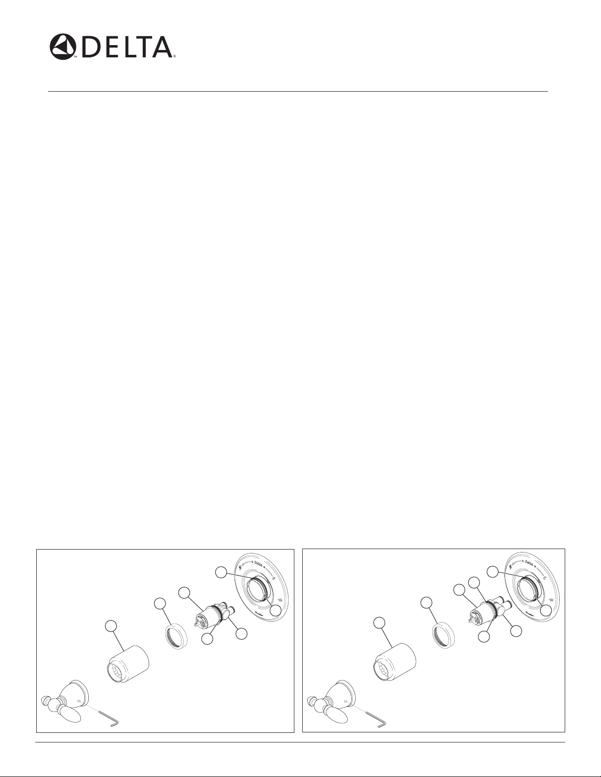
4. Pull sleeve (1) off. Then, if necessary, slide the O-ring (2) toward you just below the back of the bonnet (3) on the body. Do not pull the
O-ring over the bonnet. Note: When the sleeve (1) is reinstalled, it will slide on this O-ring.
5. WARNING: BE SURE WATER SUPPLIES ARE SHUT OFF!
6. Unscrew the brass bonnet (3) counterclockwise.
7. Determine which series cartridge is currently installed in order to know which replacement cartridge to use. If the cap (4) is white,
a 1300/1400 series cartridge (RP19804) is currently installed. If the cap (4) is grey, a 13/14 MultiChoice™ cartridge (RP46074) is
currently installed. Note: Cartridges are not interchangeable.
8. Remove the cartridge from the body. If a 13/14 MultiChoice™ cartridge (RP46074) is installed, place a flat head screwdriver in the notch (5)
of the cap and turn to raise out of the body.
Note: If a 1300/1400 cartridge (RP19804) is installed, do not pry the cartridge out of the body with a screwdriver. Reinstall the
handle on the brass stem and rotate counterclockwise while lifting the cartridge out of the two notches (6) on the sides of the body.
9. CAUTION! Do not twist the cap (4) and the lower housing (7) of the new cartridge to take it apart. If the parts are separated for any
reason, be sure to lock each together by twisting the parts together until the cap and housing snap together. WARNING! Never take the
lower housing apart.
1. 1300/1400 Cartridge Installation:
Install the cartridge with the wording “Hot Side” located on the hot water inlet side. Press into valve body, making sure the keys (8) are fully
engaged with the slots of the body (6). Note: For back-to-back or reverse installations (hot on right, cold on left) install cartridge with the
wording “Hot Side” on the hot water inlet side. If using a 13/14 MultiChoice™ cartridge, see step 1A below. If not, continue to step 2.
1A.
13/14 Multi-Choice Cartridge Installation:
Install the cartridge with the wording “Hot Side” located on the hot water inlet side. Press into valve body, making sure the keys (8) are fully
engaged with the slots of the body (6). Note: For back-to-back or reverse installations (hot on right, cold on left) install cartridge with the
wording “Hot Side” on the hot water inlet side.
2. Reassemble the brass bonnet (3).
3. Slide the sleeve (1) over the O-ring.
4. Remove and throw away the black retention plug (not illustrated), on 1300/1400 cartridge only, from the brass stem.
5. See the reverse side for rotational limit stop adjustment.
6. Reinstall the handle, then proceed to step 7.
7. FLUSH YOUR SYSTEM. Turn on water supplies. Check for leaks and let supply lines flush for one minute without moving handle. If you
have a showerhead remove and divert water to it and flush for 30 seconds. This will remove any debris from the supply lines that can
damage internal parts of the faucet and create leaks. BE SAFE! After you have finished the repair, turn on tub/shower valve to make sure
COLD WATER FLOWS FIRST.
1300/1400 Cartridge
RP19804
1
2
4
3
8
7
6
13/14 MultiChoice™ Cartridge
RP46074
3
1
2
5
4
8
7
48027 48027 48027 48027 48027 48027
6
10/13/06 Rev. B
1
Page 2
1300/1400 & 13/14 MultiChoice™ Cartridge
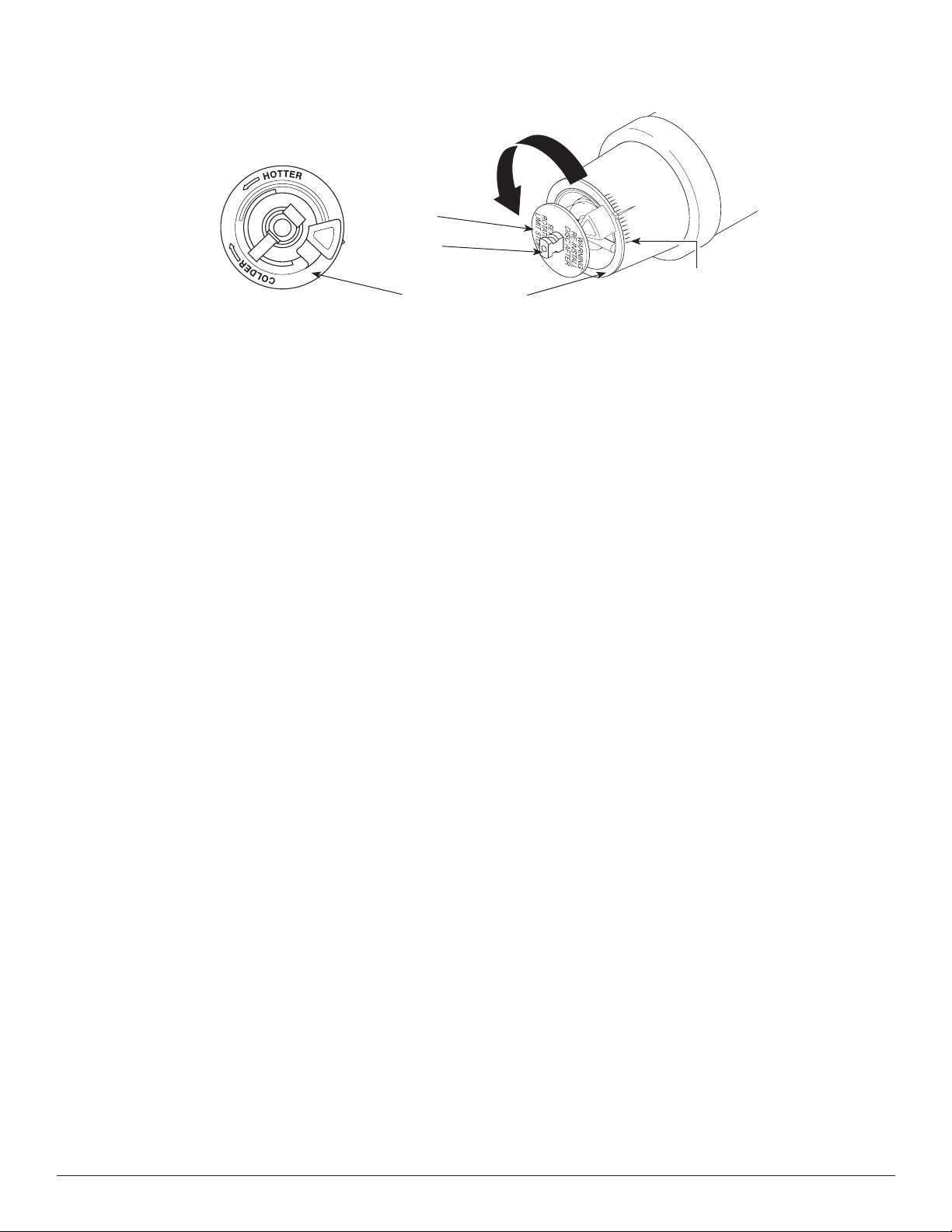
Hotter
Disc
Stem
1st Position
Rotational Limit Stop
1. ADJUSTING THE ROTATIONAL LIMIT STOP:
IMPORTANT: The Rotational Limit Stop is used to limit the amount of hot water available such that, if set properly, the user will not be scalded if the
handle accidentally is rotated all the way to “hot” when a person is showering or filling a tub. The first position allows the LEAST amount of hot water to
mix with the cold water in the system. In the first position the water will be the coldest possible when the handle is turned all the way to hot. As you move
the Rotational Limit Stop counterclockwise, you progressively add more and more hot water in the mix. The last position to the left will result in the greatest
amount of hot water to the mix, and the greatest risk of scald injury if someone accidentally turns the valve handle all the way to the hot side
while showering or filling a tub.
WARNING: In some instances, setting the Rotational Limit Stop in the hottest position (full counterclockwise) could result in scald injury. It is
necessary to adjust the Rotational Limit Stop so that the water coming out of the valve will not scald the user when the handle of the valve is
rotated to the hot side.
• According to the majority of industry standards, the maximum allowable temperature of the water exiting the valve is 120°F (Your local plumbing codes
may require a water temperature less than 120°F).
• The Rotational Limit Stop may need to be readjusted seasonally if the inlet water temperature changes. For example, during the winter, the cold water
temperature is colder than it is during the summer which could result in varying outlet temperatures. A water temperature for a comfortable bath or
shower is typically between 90°F - 110°F.
• Run the water so that the cold water is as cold as it will get and hot water is as hot as it will get. Place the handle on the stem and rotate the handle
counterclockwise until the handle stops.
• Place a thermometer in a plastic tumbler and hold in the water stream. If the water temperature is above 120°F, the Rotational Limit Stop must be
repositioned clockwise to decrease valve outlet water temperature to be less than 120°F or to meet the requirements of your local plumbing codes.
• To adjust the temperature of the water coming out of the valve, pull the disc back to a position where it is possible to remove the Rotational Limit Stop
and readjust the teeth engagement position to the desired temperature. Clockwise will decrease the outlet temperature, counterclockwise will increase
the outlet temperature. Temperature change per tooth (notch) could be 4° - 16°F based on inlet water conditions. Repeat as necessary. Push disc until
fully seated. WARNING: Failure to re-install Disc after setting Rotational Limit Stop could result in scald injury.
• MAKE SURE COLD WATER FLOWS FROM THE VALVE FIRST. MAKE SURE WATER FLOWING FROM THE VALVE AT THE HOT TEST FLOW
POSSIBLE DOES NOT EXCEED 120°F OR THE MAXIMUM ALLOWED BY YOUR LOCAL PLUMBING CODE.
2
48027 Rev. B
 Loading...