

Page 1
48028 48028 48028 48028 48028 48028
RP48026
1700 &17 Cartridges
Installation Instructions
1. Read complete instructions and familiarize yourself with the illustrations before beginning. Plumber installation is recommended.
2. WARNING! SHUT OFF WATER SUPPLIES BEFORE DISASSEMBLING TUB SHOWER VALVE.
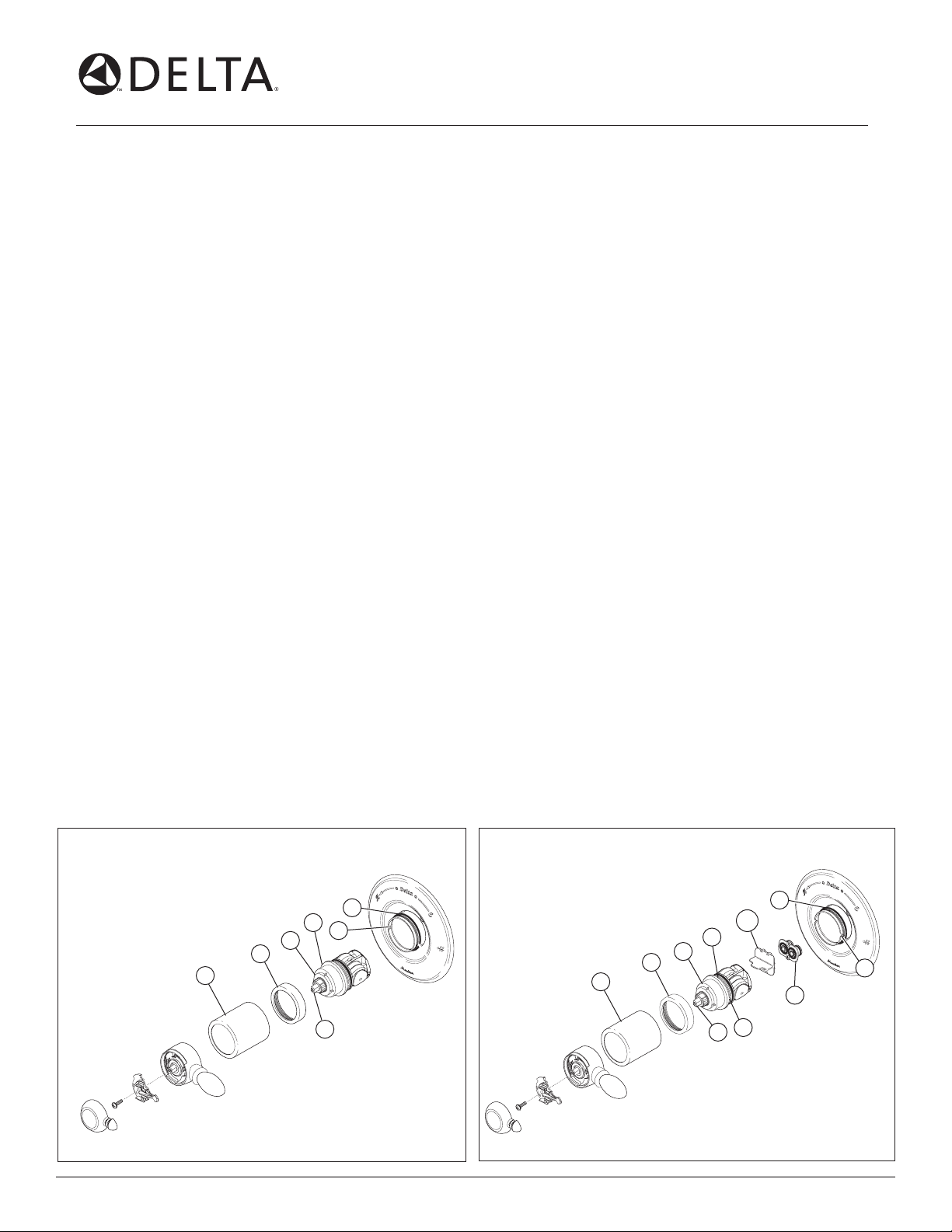
3. Remove handle.
4. Pull sleeve (1) off. Then, if necessary, slide the O-ring (2) toward you just below the back of the bonnet (3) on the body. Do not pull the
O-ring over the bonnet. Note: When the sleeve (1) is reinstalled, it will slide on this O-ring.
5. WARNING: BE SURE WATER SUPPLIES ARE SHUT OFF!
6. Unscrew the brass bonnet (3) counterclockwise.
7. Determine which series cartridge is currently installed in order to know which replacement cartridge to use. If the cap (4) is white, a
1700 series cartridge (RP32104) is currently installed. If the cap (4) is grey, a 17 MultiChoice™ cartridge (RP46463) is currently installed.
Note: Cartridges are not interchangeable.
8. Remove the cartridge from the body. If a 17 MultiChoice™ cartridge is installed, place a flat head screwdriver in the notch (5) of the cap
and turn to raise out of the body. To remove 17 MultiChoice™ adapter (6), remove screw and pry out adapter.
Note: If a 1700 cartridge is installed, do not pry the cartridge out of the body with a screwdriver. Reinstall the handle on the
stem (7) and rotate counterclockwise while lifting the cartridge out of the slot (8) on the body.
1. 1700 Cartridge Installation:
Install the Cartridge so the wording “Hot Side” is on the left. Press into valve body, making sure the square key (9) is fully engaged with the
slot of the body (8). Note: For back-to-back or reverse installations (hot on right, cold on left) remove the white cap and rotate 180° so
that the square key is on the right. Place cap on lower housing and reinstall square key into slot. If using a 17 MultiChoice™ cartridge, see
step 1A below. If not, continue to step 2.
1A.
17 MultiChoice™ Cartridge Installation:
Press in 17 MultiChoice™ adapter (6) so that the screw is on the bottom side. Tighten screw to secure. Remove black retainer (10), and
make sure all parts remain properly seated in adapter.
Install the cartridge so the wording “Hot Side” is on the left. Press into valve body, making sure the keys (9) are fully engaged with the slots
of the body (8). For back-to-back or reverse installations (hot on right, cold on left) install the cartridge so the wording “HOT SIDE”
appears on the hot water inlet side.
2. Reassemble the brass bonnet (3) .
3. Slide the sleeve (1) over the O-ring.
4. See the reverse side for rotational limit stop adjustment.
5. Reinstall the handle, then proceed to step 6.
6. FLUSH YOUR SYSTEM. Turn handle to full on “hot and cold mix” position. Turn on water supplies. Check for leaks and let supply lines flush
for one minute without moving handle. If you have a showerhead remove and divert water to it and flush for 30 seconds. This will remove
any debris from the supply lines that can damage internal parts of the faucet and create leaks. BE SAFE! After you have finished the repair,
turn on tub/shower valve to make sure COLD WATER FLOWS FIRST.
48028 48028 48028 48028 48028 48028
1700 Cartridge
RP32104
6/26/06 Rev. A
17 MultiChoice™ Cartridge
RP46463
2
9
4
3
1
8
3
1
7
5
4
7
1
2
10
8
6
9
Page 2
Adjusting the Rotational Limit Stop
H
O
T
T
E
R
1700 Cartridge
4.
3
4
1
Hotter
Más Caliente
Plus Chaud
st
1
2
Colder
Más Fría
Plus Froid
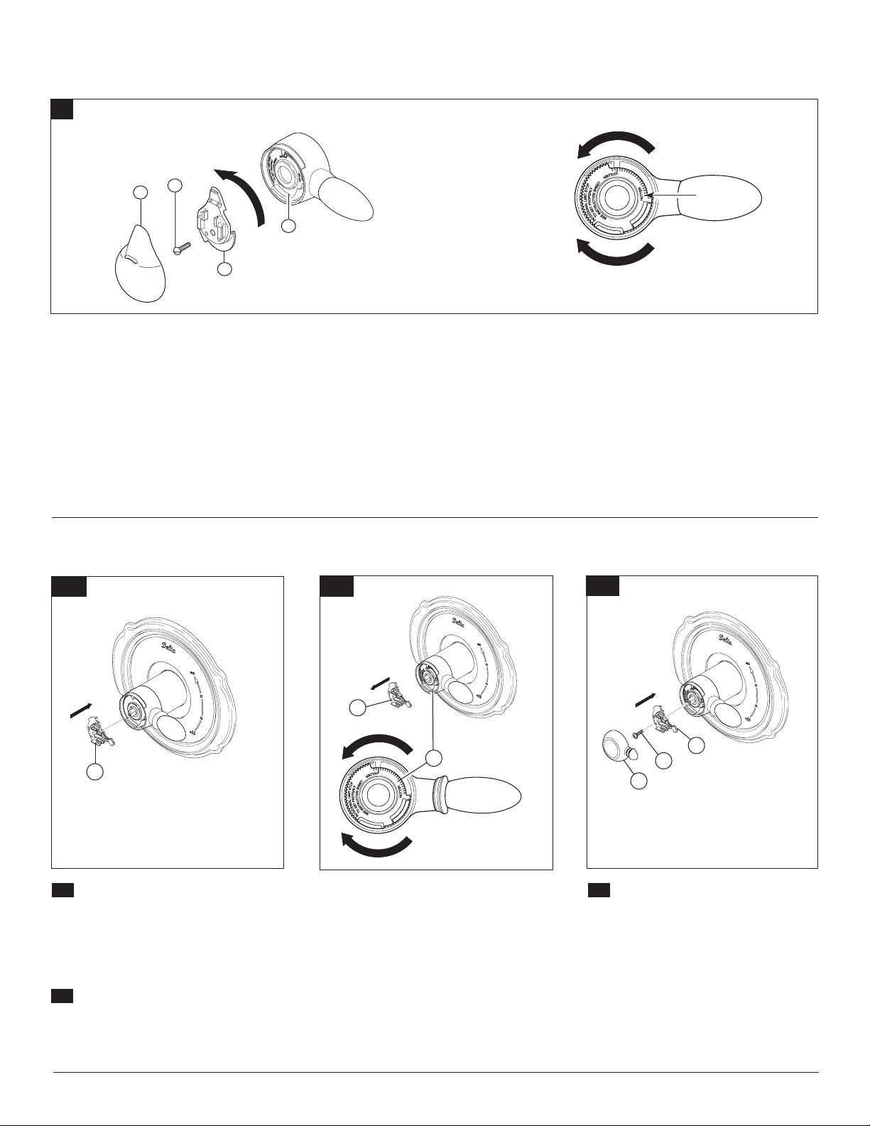
ADJUST THE ROTATIONAL LIMIT STOP! Turn on
water supplies; LET
HOT AND COLD WATER IS AS HOT/COLD
AS
POSSIBLE. Place thermometer in a plastic
tumbler, and hold the tumbler in the water stream.
Record the temperature reading. If the water
temperature is above 120°F, remove the temperature
control knob (1) and rotate the limit stop (2)
clockwise one tooth for every 2°F (approximate)
change in temperature. If water temperature is cooler
than desired, rotate the limit stop counter-clockwise.
Replace temperature control knob, turn faucet off
THE WATER RUN UNTIL BOTH
Adjusting the Rotational Limit Stop
17 MultiChoice™ Cartridge
4A.
1
and then back on and recheck water temperature.
MAKE
SURE COLD WATER FLOWS FIRST.
Repeat as necessary. Secure temperature control
knob with screw (3) and snap control cover (4)
onto knob. NOTE: Secure screw until handle wobble
is reduced, DO
Overtightening will result in difficulty to operate
temperature control knob. Screw is self locking.
IMPORTANT: The first position of the Rotational Limit
Stop (the Limiter) is that position that restricts the
rotation of the stem the most and is at the maximum
NOT FULLY TIGHTEN.
4B.
1
Hotter
2
clockwise setting. According to industry standards, the
maximum allowable temperature of the water exiting
from the valve is 120
your local area. The Rotational Limit Stop may need to
be readjusted if the inlet water temperature changes.
For instance, during the winter, the cold water
temperature is colder than it is during the summer
which could result in varying outlet temperatures.
Typical temperature for a comfortable bath or shower is
between
90o–110
o
F. This temperature may vary in
o
F.
4C.
1
2
3
Place the temperature control knob (1)
4A.
on volume handle and rotate to the mixed position
(if required). DO NOT SECURE WITH SCREW.
Turn on water supplies; let the water run until
both hot and cold water is as hot/cold as possible.
Place thermometer in a plastic tumbler, and hold
the tumbler in the water stream. Record the tem
perature reading.
If the water temperature is above 120°F,
4B.
remove the temperature control knob (1) and ro
tate the limit stop (2) clockwise one tooth for every
4°F - 6°F (approximate) change in temperature. If
water temperature is cooler than desired, rotate
the limit stop counterclockwise.
Colder
IMPORTANT:
Limit Stop (the Limiter) is that position that
restricts the rotation of the stem the most and
is at the maximum clockwise setting. According
to industry standards, the maximum allowable
temperature of the water exiting from the valve
-
is 120o F. This temperature may vary in your local
area. The Rotational Limit Stop may need to be
readjusted if the inlet water temperature changes.
For instance, during the winter, the cold water
temperature is colder than it is during the sum-
-
mer which could result in varying outlet tempera
tures. Typical temperature for a comfortable bath
or shower is between 90
The first position of the Rotational
o
–110o F.
-
2
Secure temperature control knob (1) with
4C.
screw (2) and snap control cover (3) onto
knob. NOTE:
wobble is reduced, DO NOT FULLY
TIGHTEN. Overtightening will result in dif-
ficulty to operate temperature control knob.
Screw is self locking.
Secure screw until handle
48028 Rev. A
 Loading...