

Page 1

RMC70 Motion Controller
And
RMC70Tools Software
User Manual
Version 1.10.0 May 7, 2004
Page 2

RMC70 and RMC70Tools User Manual
Copyright © 2004, Delta Computer Systems, Inc. All Rights Reserved.
deltamotion.com
ii Delta Computer Systems, Inc.
Page 3

Condensed Contents
1. Introducing the RMC70 Series........................................................1
Overview of the RMC70 capabilities and applications.
2. Starting Up the RMC70...................................................................5
A Step-by-step guide to quickly get up and running.
3. Control Features...........................................................................19
Control Types and more…
4. Programming ...............................................................................37
A guide to programming the RMC70.
5. Using RMC70Tools........................................................................57
Detailed information on how to use the RMC70 motion control software.
6. Modules........................................................................................ 79
CPU, Axis and Expansion modules.
7. Registers.................................................................................... 107
Detailed information on all RMC70 registers.
8. Communication Types ................................................................ 113
Serial, PROFIUBUS, and more…
9. Troubleshooting......................................................................... 131
Hints and assistance. Detailed information on error codes.
10. Command Reference .................................................................. 181
Detailed information on how to use each RMC70 command.
11. RMC70 Specifications ................................................................. 215
Hardware specifications of the RMC70.
12. Index ......................................................................................... 239
deltamotion.com iii
Page 4

RMC70 and RMC70Tools User Manual
iv Delta Computer Systems, Inc.
Page 5

Table Of Contents
Introducing the RMC70 Series...................................................................... 1
RMC70 Series Motion Controllers ............................................................................ 1
RMC70 Physical Components .................................................................................. 1
RMC70 Axis Types................................................................................................... 2
Starting Up the RMC70................................................................................. 5
RMC70 Start-up Procedure...................................................................................... 5
Scaling...................................................................................................................11
Tuning....................................................................................................................11
Tuning Overview................................................................................................................................... 12
Tuning a Position Axis.......................................................................................................................... 13
Control Features......................................................................................... 19
RMC70 Control Features.........................................................................................19
Halts ......................................................................................................................19
Halts Overview...................................................................................................................................... 19
External Halt ......................................................................................................................................... 21
Closed Loop Halt .................................................................................................................................. 21
Open Loop Halt..................................................................................................................................... 22
Open Loop with Disable Output Halt.................................................................................................... 22
Control Modes........................................................................................................23
Control Modes Overview...................................................................................................................... 23
Closed Loop Control............................................................................................................................. 24
Open Loop Control................................................................................................................................ 24
Pressure Limit ....................................................................................................................................... 25
Position-Pressure Control...................................................................................................................... 26
PFID Control......................................................................................................................................... 26
Plots ......................................................................................................................28
Using Plots............................................................................................................................................ 29
Advanced Plot Capabilities................................................................................................................... 29
Configuring Plots .................................................................................................................................. 30
Triggering Plots..................................................................................................................................... 32
Selecting Data to Plot............................................................................................................................ 33
Assigning Plots to Axes ........................................................................................................................ 34
Using Plots with a Host Controller........................................................................................................ 35
Programming ............................................................................................. 37
User Programs.......................................................................................................37
User Programs Overview...................................................................................................................... 37
Creating User Programs........................................................................................................................ 38
Verifying User Programs....................................................................................................................... 40
Running User Programs........................................................................................................................ 40
Labeling Steps....................................................................................................................................... 41
Expressions............................................................................................................42
Expressions Overview........................................................................................................................... 42
Assignment Expressions........................................................................................................................ 42
Logical Expressions .............................................................................................................................. 43
Functions............................................................................................................................................... 44
Operators............................................................................................................................................... 45
Troubleshooting Expressions................................................................................................................ 46
Link Types..............................................................................................................47
deltamotion.com v
Page 6

RMC70 and RMC70Tools User Manual
Link Types Overview............................................................................................................................ 47
Link Type: End...................................................................................................................................... 48
Link Type: Immediate........................................................................................................................... 48
Link Type: Delay .................................................................................................................................. 48
Link Type: Wait For.............................................................................................................................. 49
Link Type: Jump................................................................................................................................... 49
Link Type: Delay Jump......................................................................................................................... 50
Link Type: Conditional Jump................................................................................................................ 50
Programming Overview .........................................................................................51
Tasks .....................................................................................................................52
Variables................................................................................................................53
PreScan Table ........................................................................................................55
Data Types.............................................................................................................56
Using RMC70Tools...................................................................................... 57
Using RMC70Tools .................................................................................................57
RMC70Tools IDE.....................................................................................................57
RMC70Tools Menu Bar............................................................................................58
RMC70Tools Project Pane ......................................................................................59
Axis Tools Pane......................................................................................................60
Event Log Monitor..................................................................................................61
Uploading and Downloading Axes..........................................................................62
Command Tool .......................................................................................................62
Output Pane...........................................................................................................63
Axes Status Registers Pane....................................................................................63
Hiding and Showing Columns............................................................................................................................64
Step Editor.............................................................................................................64
Program Monitor....................................................................................................64
Shortcut Keys ........................................................................................................65
Programming ...................................................................................................................................................... 66
Go Online, GO Offline .............................................................................................68
Editors ...................................................................................................................68
Axes Parameters Pane........................................................................................................................... 68
Indirect Data Map Editor....................................................................................................................... 70
Custom Data Map Editor....................................................................................................................... 71
Using Editors......................................................................................................................................... 71
Variable Table Editor............................................................................................................................ 73
Plot Manager..........................................................................................................75
Plot Manager: Viewing Plots ................................................................................................................ 75
Plot Manager Overview......................................................................................................................... 76
Plot Manager Elements ......................................................................................................................... 77
Modules...................................................................................................... 79
CPU Modules ..........................................................................................................79
RMC75S................................................................................................................................................ 79
RMC75S CPU Module ....................................................................................................................................... 79
RMC75S Wiring................................................................................................................................................. 79
RMC75P................................................................................................................................................ 79
RMC75P CPU Module ....................................................................................................................................... 79
RMC75P Wiring................................................................................................................................................. 79
CPU Modules Overview ....................................................................................................................... 80
CPU Module LEDs ............................................................................................................................... 80
Axis Modules..........................................................................................................82
Axis Modules Overview........................................................................................................................ 82
Control Output....................................................................................................................................... 82
Enable Output........................................................................................................................................ 83
Fault Input............................................................................................................................................. 84
vi Delta Computer Systems, Inc.
Page 7

Table of Contents
AA......................................................................................................................................................... 85
AA Module ......................................................................................................................................................... 85
AA Axis Module Specifications ......................................................................................................................... 85
AA Wiring .......................................................................................................................................................... 86
AA LEDs............................................................................................................................................................ 88
Analog Scaling for the AA Module .................................................................................................................... 89
MA ........................................................................................................................................................ 90
MA Axis Module................................................................................................................................................ 90
MAx Supported Transducer Options .................................................................................................................. 90
MA Axis Module Specifications......................................................................................................................... 91
MAx Wiring........................................................................................................................................................ 92
MA LEDs............................................................................................................................................................ 96
MDT Scaling....................................................................................................................................................... 96
MDT Transducer Fundamentals..........................................................................................................................98
SSI Scaling.......................................................................................................................................................... 99
SSI Transducer Fundamentals........................................................................................................................... 100
Expansion Modules ..............................................................................................101
Expansion Modules Overview ............................................................................................................ 101
AP2...................................................................................................................................................... 102
AP2 Expansion Module .................................................................................................................................... 102
AP2 Wiring....................................................................................................................................................... 103
AP2 LEDs......................................................................................................................................................... 104
Analog Scaling for the AP Module................................................................................................................... 104
Troubleshooting....................................................................................... 107
Troubleshooting Overview ...................................................................................107
Error Codes..........................................................................................................107
Technical Support ................................................................................................111
Registers.................................................................................................. 113
RMC70 Register Address Format..........................................................................113
RMC70 Register Map ............................................................................................114
Status Registers...................................................................................................127
Axis Status Registers Overview.......................................................................................................... 127
Common.............................................................................................................................................. 127
Error Bits Register ............................................................................................................................................ 127
Last Error Number Register.............................................................................................................................. 129
Read Response.................................................................................................................................................. 130
Status Bits Register........................................................................................................................................... 131
Input .................................................................................................................................................... 133
Actual Acceleration...........................................................................................................................................133
Actual Differential Force...................................................................................................... ............................ 134
Actual Differential Force Rate.......................................................................................................................... 134
Actual Force A, Actual Force B........................................................................................................................ 135
Actual Position.................................................................................................................................................. 135
Actual Pressure/Force....................................................................................................................................... 135
Actual Pressure/Force Rate............................................................................................................................... 136
Actual Velocity................................................................................................................................................. 136
Counts............................................................................................................................................................... 136
Volts.................................................................................................................................................................. 137
Counts A, Counts B .......................................................................................................................................... 137
Raw Counts....................................................................................................................................................... 137
Raw Counts A, Raw Counts B.......................................................................................................................... 138
Output.................................................................................................................................................. 138
Control Output.................................................................................................................................................. 138
Primary Control................................................................................................................................... 138
Acceleration Feed Forward Term ..................................................................................................................... 138
Differential Output Term..................................................................................................................................139
Integral Output Term ........................................................................................................................................ 139
PFID Output...................................................................................................................................................... 139
deltamotion.com vii
Page 8

RMC70 and RMC70Tools User Manual
Position Error.................................................................................................................................................... 139
Proportional Output Term................................................................................................................................. 140
Velocity Error...................................................................................................................................................140
Velocity Feed Forward Term............................................................................................................................ 140
Jerk Feed Forward Term................................................................................................................................... 141
Primary Target..................................................................................................................................... 141
Command Position............................................................................................................................................ 141
Command Velocity...........................................................................................................................................141
Target Acceleration........................................................................................................................................... 142
Target Position.................................................................................................................................................. 142
Target Velocity.................................................................................................................................................142
Secondary Control............................................................................................................................... 143
Pressure/Force Differential Term...................................................................................................................... 143
Pressure/Force Error ......................................................................................................................................... 143
Pressure/Force Feed Forward Term.................................................................................................................. 143
Pressure/Force Proportional Term .................................................................................................................... 143
Pressure/Force Rate Feed Forward Term.......................................................................................................... 144
Secondary Target................................................................................................................................. 144
Command Pressure/Force.................................................................................................................................144
Target Pressure/Force ....................................................................................................................................... 144
Parameter Registers ............................................................................................145
Axis Parameter Registers Overview.................................................................................................... 145
Feedback ............................................................................................................................................. 145
Input Filters....................................................................................................................................................... 145
Actual Acceleration Filter............................................................................................................................. 145
Actual Position Filter....................................................................................................................................145
Actual Pressure/Force Filter.......................................................................................................................... 146
Actual Pressure/Force Rate Filter..................................................................................................................146
Actual Velocity Filter.................................................................................................................................... 146
Pressure & Force............................................................................................................................................... 147
Force A Offset, Force B Offset..................................................................................................................... 147
Force A Scale, Force B Scale........................................................................................................................ 147
Pressure/Force Offset.................................................................................................................................... 148
Pressure/Force Scale..................................................................................................................................... 148
Transducer Specific...........................................................................................................................................148
Feedback Type.............................................................................................................................................. 148
MDT Type .................................................................................................................................................... 149
Absolute/Incremental........................................................................................................................................ 152
Noise Error Rate ............................................................................................................................................... 152
Position Offset .................................................................................................................................................. 153
Position Scale.................................................................................................................................................... 153
Linear/Rotary.................................................................................................................................................... 154
Stop Threshold.................................................................................................................................................. 154
Velocity Deadband............................................................................................................................................ 154
Velocity Offset.................................................................................................................................................. 155
Halting................................................................................................................................................. 155
Auto Stop Configuration................................................................................................................................... 155
Halt Group Number .......................................................................................................................................... 157
Closed Loop Halt Deceleration......................................................................................................................... 157
Open Loop Halt Ramp...................................................................................................................................... 157
Output.................................................................................................................................................. 158
Deadband Tolerance ......................................................................................................................................... 158
Directional Gain Ratio...................................................................................................................................... 159
Invert Output Polarity....................................................................................................................................... 160
Output Bias.......................................................................................................................................................160
Output Deadband..............................................................................................................................................160
Output Filter...................................................................................................................................................... 162
Output Limit ..................................................................................................................................................... 162
Output Scale...................................................................................................................................................... 163
Fault Input Polarity...........................................................................................................................................163
Enable Output Behavior.................................................................................................................................... 163
viii Delta Computer Systems, Inc.
Page 9

Table of Contents
Primary Control................................................................................................................................... 164
In Position Tolerance........................................................................................................................................ 164
Position Error Tolerance................................................................................................................................... 164
At Velocity Tolerance....................................................................................................................................... 165
Jerk Feed Forward............................................................................................................................................. 165
Velocity Error Tolerance...................................................................................................................................166
Integrator Mode ................................................................................................................................................ 166
Position Proportional Gain..................................................................................................... ........................... 167
Position Integral Gain....................................................................................................................................... 167
Position Differential Gain................................................................................................................................. 169
Velocity Feed Forward......................................................................................................................................170
Acceleration Feed Forward............................................................................................................................... 171
Simulation........................................................................................................................................... 171
Simulate Mode.................................................................................................................................................. 171
System Gain...................................................................................................................................................... 173
Natural Frequency............................................................................................................................................. 173
Damping Factor ................................................................................................................................................ 174
Secondary Control............................................................................................................................... 174
At Pressure/Force Tolerance............................................................................................................................. 174
Pressure/Force Error Tolerance......................................................................................................................... 174
Pressure/Force Proportional Gain ..................................................................................................................... 175
Pressure/Force Integral Gain............................................................................................................................. 175
Pressure/Force Differential Gain....................................................................................................................... 176
Pressure/Force Feed Forward............................................................................................................................ 176
Pressure/Force Rate Feed Forward ................................................................................................................... 177
Pressure/Force Orientation................................................................................................................................ 177
Target .................................................................................................................................................. 178
Positive Travel Limit........................................................................................................................................ 178
Negative Travel Limit....................................................................................................................................... 179
Positive Pressure/Force Limit........................................................................................................................... 179
Negative Pressure/Force Limit.......................................................................................................................... 179
Communication Types .............................................................................. 181
RMC70 Communications Overview.......................................................................181
Indirect Data Map ................................................................................................181
RS-232 Monitor Port ............................................................................................182
PROFIBUS............................................................................................................184
PROFIBUS-DP Communications Overview....................................................................................... 184
PROFIBUS Configuration .................................................................................................................. 185
PROFIBUS Mode 8-1......................................................................................................................... 187
PROFIBUS Mode 16-1....................................................................................................................... 192
PROFIBUS Mode 8-7......................................................................................................................... 193
Configuring a PROFIBUS-DP Network with COM PROFIBUS....................................................... 194
Configuring a PROFIBUS-DP Network with SST Profibus Configuration........................................ 196
Configuring a PROFIBUS-DP Network with SyCon ......................................................................... 197
Serial (RS-232/485) ............................................................................................198
Serial Communications Overview....................................................................................................... 198
Configuration and Wiring ................................................................................................................... 200
Line Drivers: RS-232/485................................................................................................................................. 200
Configuring the RMC7xS Serial Communications........................................................................................... 201
Serial Network Topologies ............................................................................................................................... 202
RS-232 Wiring for the RMC70......................................................................................................................... 204
RS-485 Wiring for the RMC70......................................................................................................................... 205
RS-485 Termination and Biasing...................................................................................................................... 207
RMC70 Serial Protocols...................................................................................................................... 209
DF1 Protocol (Full-and Half-Duplex)............................................................................................................... 209
Modbus/RTU Protocol...................................................................................................................................... 213
Command Reference ................................................................................ 215
deltamotion.com ix
Page 10

RMC70 and RMC70Tools User Manual
RMC70 Commands Overview................................................................................215
RMC70 Commands ...............................................................................................215
General Commands..............................................................................................217
RMC70 Command: No-op (0) ............................................................................................................ 217
RMC70 Command: Clear Faults (4)................................................................................................... 217
RMC70 Command: Initialize Axes (7) ............................................................................................... 217
RMC70 Command: Fault Controller (8).............................................................................................218
RUN Mode (98) .................................................................................................................................. 219
PROGRAM Mode (99)....................................................................................................................... 219
Motion Commands ...............................................................................................220
Motion Commands.............................................................................................................................. 220
Open Loop........................................................................................................................................... 221
RMC70 Command: Direct Drive (9).................................................................................................................221
RMC70 Command: Open Loop Rate (10) ........................................................................................................ 221
RMC70 Command: Open Loop Absolute (11)................................................................................................. 222
RMC70 Command: Open Loop Relative (12) .................................................................................................. 223
Point-to-Point...................................................................................................................................... 224
RMC70 Command: Move Absolute (20).......................................................................................................... 224
RMC70 Command: Move Relative (21)........................................................................................................... 224
RMC70 Command: Quick Move Absolute (15)...............................................................................................225
RMC70 Command: Quick Move Relative (16) ................................................................................................ 226
RMC70 Command: Time Move Absolute (23)................................................................................................. 226
RMC70 Command: Time Move Relative (24).................................................................................................. 227
Specialty.............................................................................................................................................. 227
RMC70 Command: Speed at Position (36)....................................................................................................... 227
Stops.................................................................................................................................................... 228
RMC70 Command: Closed Loop Halt (1)........................................................................................................ 228
RMC70 Command: Open Loop Halt (2)........................................................................................................... 228
RMC70 Command: Disable Output (3)............................................................................................................ 229
RMC70 Command: Hold Current Position (5)..................................................................................................229
RMC70 Command: Stop (6)............................................................................................................................. 229
System.................................................................................................................230
RMC70 Command: Update Flash (110).............................................................................................. 230
Pressure Control ..................................................................................................230
RMC70 Command: Enable/Disable Pressure Limit (40).................................................................... 230
RMC70 Command: Ramp Pressure(41).............................................................................................. 231
Set Parameters ....................................................................................................231
RMC70 Command: Set Integrator Mode (71)..................................................................................... 232
RMC70 Command: Set Enable Output (67)........................................................................................ 232
RMC70 Command: Set Actual Position (49)...................................................................................... 232
RMC70 Command: Set Target Position (48)...................................................................................... 233
RMC70 Command: Read Register (111)............................................................................................ 233
RMC70 Command: Write Register (112)........................................................................................... 233
Programming.......................................................................................................234
RMC70 Command: Stop Task (91)..................................................................................................... 234
RMC70 Command: Start Task (90) .................................................................................................... 234
Plots ....................................................................................................................235
RMC70 Command: Enable/Disable Plot Trigger (104)...................................................................... 235
RMC70 Command: Rearm Plot (103).................................................................................................236
RMC70 Command: Start Plot (100).................................................................................................... 236
RMC70 Command: Stop Plot (101).................................................................................................... 236
RMC70 Command: Trigger Plot (102)...............................................................................................237
Step Editor Commands.........................................................................................237
RMC70 Command: Expression (113).................................................................................................237
RMC70 Specifications ............................................................................... 239
RMC70 Specifications...........................................................................................239
Wiring Guidelines.................................................................................................239
x Delta Computer Systems, Inc.
Page 11

Table of Contents
RMC70 Part Numbering........................................................................................240
Index ....................................................................................................... 243
deltamotion.com xi
Page 12

Page 13

RMC70Tools On-line Help
The RMC70Tools on-line help provides the most complete and up-to-date information available
for the RMC70 and RMC70Tools. To ensure you have the latest help file, download the latest
version of RMC70Tools from Delta's website www.deltamotion.com.
Troubleshooting
See the Troubleshooting topic.
Customer Support
Delta support is ready to assist you. Call should you have questions or need help:
Telephone: 360-254-8688
Fax: 360-254-5435
24-hour paging: 360-699-7784
E-mail: support@deltamotion.com
Website: http://www.deltamotion.com
Paper Copy of On-line Help
A manual containing the same information as the online help is available as a Portable
Document Format (PDF) file from Delta's website www.deltamotion.com. If you need a
hard-copy manual, contact Delta by telephone at 360-254-8688 or email at
sales@deltamotion.com.
deltamotion.com xiii
Page 14

Page 15

Disclaimer
Although great effort has been taken to ensure the accuracy of the information in this
documentation, it is intended to be used only as a guide. Knowledge of motion control,
hydraulic servos, electric servos, transducers, and safety rules is required. Delta Computer
Systems, Inc. does not accept responsibility for problems resulting from errors or omissions in
this documentation. The information in this documentation is subject to change without notice.
Neither Delta Computer Systems, Inc. nor anyone else involved in the creation, production, or
delivery of this product shall be liable for any direct, indirect, consequential injuries and or
damages arising out of the use, the results of use, or the inability to use this product.
All brand names and trademarks referenced in this manual are the property of their respective
owners.
RMC70 Warranty
GENERAL
These general terms and conditions of sale of Delta Computer Systems, Inc (Delta), along
with any written Delta quotation, exclusively will govern the sale or licensing by Delta of
all goods and services (including hardware, firmware, and software products, training,
support, parts and repair services) furnished hereunder. No additions or modifications
will be binding on Delta unless agreed to in writing by an authorized representative of
Delta.
WARRANTY
Hardware products will conform to Deltas material specifications and be free of defects in
material and workmanship under normal and proper use for a period of one (1) year from
date of shipment to Customer by Delta or its authorized distributor. Repaired or
replacement products are similarly warranted for six (6) months or the remainder of the
original warranty term, whichever is longer.
Non-warranty repaired or replacement products (which may be new or reconditioned) are
warranted to be free of defects in materials and workmanship for six (6) months from
date of shipment from Delta.
Standard firmware and software will perform in accordance with Deltas published
specifications when used with Delta-specified hardware for a period of one (1) year from
date of shipment to Customer by Delta or its authorized distributor. Delta makes no
representation or warranty, express or implied, that the operation of the firmware or
software will be uninterrupted or error-free, or will meet or satisfy the Customers
intended use or requirements. Corrections are warranted for a period of six (6) months
or the remainder of the original warranty term, whichever is longer.
Deltas sole liability under this warranty shall be, at Deltas discretion, to repair or replace
product found defective or to issue Customer credit for the purchase price of defective
product. Customer may obtain service under this warrant if: a) within the warranty
period Customer notifies Delta of the defective product and obtains a Return Material
Authorization (RMA) from Delta; b) Customer returns product to Delta, postage prepaid,
in compliance with the RMA instructions, and c) Delta, upon inspection, confirms the
existence of the defect, and determines that the product has not been subject to misuse,
neglect, accident, or improper installation, operation, or application, or has been repaired
or altered by others. Any warrantee service (consisting of time, travel and expenses
relating to such services) performed other than at Delta, will be at Customers expense.
THIS WARRANTY IS IN LIEU OF ANY OTHER WARRANTY, EXPRESS OR IMPLIED. DELTA
DISCLAIMS ANY IMPLIED WARRANTY OF MERCHANTABILITY AND FITNESS FOR A
PARTICULAR PURPOSE. DELTAS RESPONSIBILITY TO REPAIR OR REPLACE DEFECTIVE
PRODUCTS IS THE SOLE AND EXCLUSIVE REMEDY PROVIDED TO THE CUSTOMER FOR
BREACH OF THIS WARRANTY.
LIMITATION OF LIABILITY
deltamotion.com xv
Page 16

RMC70 and RMC70Tools User Manual
IN NO EVENT SHALL DELTA OR ITS DISTRIBUTORS OR VENDORS BE LIABLE FOR ANY
INDIRECT, SPECIAL, INCIDENTAL OR CONSEQUENTIAL DAMAGES ARISING OUT OF OR
CONNECTED WITH CUSTOMERS PURCHASE OR USE OF ANY PRODUCT, EVEN IF DELTA
OR THE DISTRIBUTOR OR VENDOR HAS ADVANCE NOTICE OF THE POSSIBILITY OF
SUCH DAMAGES.
RMC Return for Repair
Should an RMC require repair, refer to the Technical Support topic for return details.
xvi Delta Computer Systems, Inc.
Page 17
1. Introducing the RMC70 Series
1.1. RMC70 Series Motion Controllers
The one- and two-axis RMC70 series
motion controllers brings the benefits
of high-performance, easy-to-use
motion control to a wide range of
industrial applications.
1.2. RMC70 Physical Components
This topic describes the physical components of the RMC70 on a basic informational level. For
mechanical and electrical specifications, see the RMC70 Specifications. For detailed function of
each module, see the respective links.
Controller Modules
An RMC70 motion controller consists of the following physical components:
• CPU Module
This module includes the main motion control processing unit. It also incorporates the
primary communication channel such as serial, DeviceNet, Ethernet, etc. and a serial
port for communications to the RMC70Tools software.
• Axis Modules
This module interfaces to a transducer and the axis drive. It is attached to the Control
Module and is sold as one unit with the Control Module. Axis Modules are transducer
specific.
Note:
The Control Module and Axis Module are one unit (called a Base Module) and make up a
complete motion controller. They are referred to as separate units solely for the purpose
of explaining their functionality.
deltamotion.com 1
Page 18

RMC70 and RMC70Tools User Manual
• Optional Expansion Modules
Up to four optional expansion modules can be added to enhance the capabilities of the
RMC70. These modules are field-changeable. Currently, an analog input expansion
module is available.
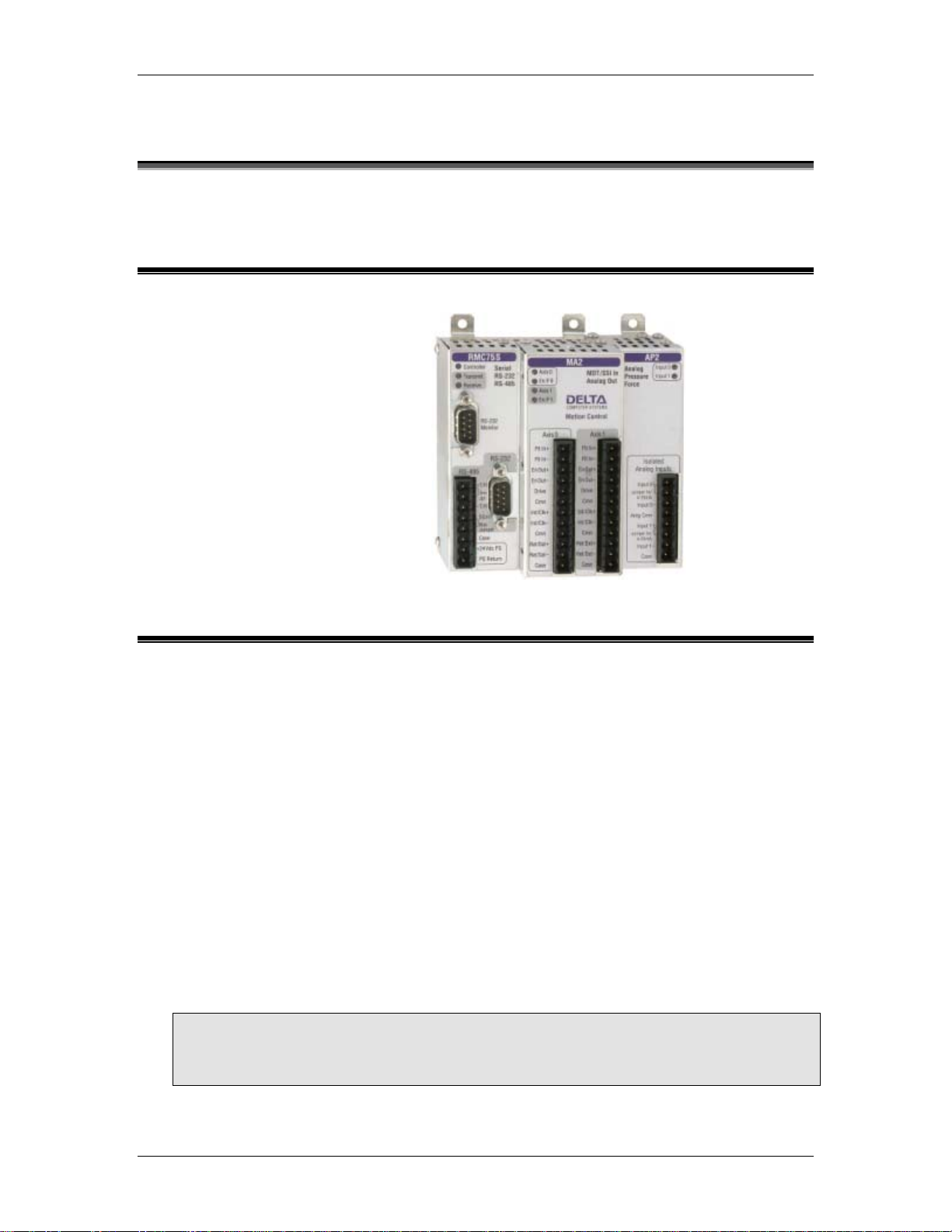
Example Module
The module below consists of a RMC75S-MA2 base module and an AP2 expansion
module.
CPU
Module
Axis
Module
Expansion
Module
1.3. RMC70 Axis Types
The RMC70 is a 1- or 2-axis motion controller with up to 3 additional reference axes (halfaxes). The axis types listed in this topic are or will be available on the RMC70. The required
inputs and outputs for each axis type constitute 1 axis. For example, a Position-Force
application may require 3 inputs and 1 output, but is still considered one axis.
Maximum Number of Axes
The maximum number of control axes on the RMC70 is 2. The maximum number of total
axes (control axes plus reference axes) is 4. A reference axis is also commonly known as
a half-axis.
Control Axes
Control axes have a Control Output and an input for transducer feedback. A control axis is
capable of controlling a system because it has a Control Output. All axes on the RMC70
Axis Modules are control axes.
Possible
Control Axis
Types
Position 1 Input 1 Analog
Velocity 1 Analog Input 1 Analog
Required
Inputs
Required
Outputs
Output
Output
Transducer
Types
MDT, SSI, Analog,
Quadrature
Analog AA1, AA2
RMC70
Modules
MA1, MA2,
AA1, AA2
2 Delta Computer Systems, Inc.
Page 19

1 Introducing the RMC70 Series
Pressure 1 Analog Input 1 Analog
Output
Force 1 or 2 Analog
Inputs
PositionPressure
PositionForce
VelocityPressure
VelocityForce
Note:
Force control axes require 1 input if a load cell is used, and require 2 inputs for differential
force on a hydraulic cylinder.
Quadrature modules are currently not available on the RMC70.
1 Input + 1
Analog Input
1 Input + 1 or 2
Analog Inputs
2 Analog Inputs 1 Analog
2 or 3 Analog
Inputs
1 Analog
Output
1 Analog
Output
1 Analog
Output
Output
1 Analog
Output
Analog Pressure Any above +
AP1 or AP2
Analog Pressure Any above +
AP1 or AP2
Adding Pressure
or Force
requires an
additional analog
pressure input
Adding
Pressure
or Force
requires an AP2
expansion
module
Reference Axes
A reference axis does not have a Control output. It only has an input for transducer
feedback. A reference axis is not capable of controlling a system. Reference axes are
commonly used in gearing and synchronization applications. The A and AP Expansion
Modules contain reference axes.
Reference Axis
Types
Position 1 Input MDT, SSI, Analog,
Velocity 1 Analog Input Analog A1, A2
Pressure 1 Analog Input Analog AP1 or AP2
Force 1 or 2 Analog
Virtual none
Required
Inputs Transducer Types
Quadrature
Analog AP1 or AP2
Inputs
Possible RMC70
Modules
A1, A2
deltamotion.com 3
Page 20

Page 21

2. Starting Up the RMC70
2.1. RMC70 Start-up Procedure
The following step-by-step procedure will help you get your system up and running quickly.
For a more detailed start-up procedure, use the Startup Guide that came with the RMC70.
TIP:
Deltas position/pressure simulators provide a simple way to test your program before
connecting the controller to a real system.
1. Provide Power to the RMC Module
a. Before providing power to the RMC for the first time, disconnect all other
wiring from the module.
b. Connect the power supply common to the PS Return pin on the RMC70
base module. The power supply should be rated for 500 mA.
c. Connnect +24 volts to the +24 Vdc PS pin.
d. For specifics on wiring, see the wiring topic. For details on the RMC power
requirements, see RMC70 Specifications.
2. Connect to Controller in RMC70Tools
a. Connect a Null-Modem cable with DB-9 connectors from a serial port on
your computer to the RMC70.
b. Open RMC70Tools.
c. On the File menu, click New Project. In the New Project Wizard, fill in
the fields and click Finish.
d. In the New Controller Wizard, type a Controller Name and choose
Automatically Detect the Controller Information.
e. Click Next.
f. Select the desired serial port, verify that the requirements in the Note are
met, and click Next.
g. You may need to wait while RMC70Tools connects to the controller. Once it
has connected, verify that the information is correct and click Finish.
3. Connect a Feedback Device
a. Important: Turn off power to the RMC70 and the feedback device before
connecting any wires!
b. For each axis you wish to connect a feedback device to, wire it to the RMC70
according to the instructions in the Wiring topic.
c. After wiring, re-apply power to the RMC70 and the feedback device.
d. In RMC70Tools, in the Project pane, click the RMC70 controller.
e. On the RMC70Tools toolbar, click the Go Online button (
red circle around the RMC70 icon in the Project pane disappears, indicating
that it is online with the RMC70.
deltamotion.com 5
). Verify that the
Page 22

RMC70 and RMC70Tools User Manual
f. The RMC70 must be properly configured before it will communicate with the
transducer(s). Refer to the procedure for your module and your transducer
type:
• MA Module - MDT transducer
i. On the RMC70Tools toolbar, click the Axis Tools button (
ii. In the Axis Parameters pane, on the Setup tab, under the
Primary Control Setup, in the Feedback Type register,
select MDT.
iii. In the MDT Type register, select the type of MDT transducer
you have. This information should be available on the MDT
datasheet. The options are:
iv. To apply the changes to the RMC70, click the Download
button (
• MA Module - SSI transducer
i. On the RMC70Tools toolbar, click the Axis Tools button (
ii. In the Axis Parameters pane, on the Setup tab, under the
Primary Control Setup, in the Feedback Type register,
select SSI.
iii. From the information in your SSI transducer data sheet, enter
the correct value for each of these registers:
ii. To apply the changes to the RMC70, click the Download
button (
b. On the RMC70Tools toolbar, click the Axis Tools
c. In the Axis Tools, in the Axis Status Registers
d. Move the axis manually and look for a corresponding
• Start/Stop Rising Edge
• Start/Stop Falling Edge
• Pulse-Width Modulated
) or press Ctrl+D.
• SSI Format - Binary or Gray
• SSI Data bits - (e.g. 24)
) or press Ctrl+D.
• AA Module - Voltage or Current
transducer
i. On the RMC70Tools toolbar, click the
Axis Tools button (
ii. In the Axis Parameters pane, on the
Setup tab, under the Primary
Control Setup, in the Input Type
register, select Voltage or Current.
iii. To apply the changes to the RMC70,
click the Download button (
press Ctrl+D.
button (
pane, on the Basic Position tab, look at the Actual
Position register. It may be changing slightly.
change in the Actual Position register. If it does not
change, recheck the wiring, verify that the Primary
Control Setup registers in the Axis Parameters
).
).
) or
).
).
6 Delta Computer Systems, Inc.
Page 23
2 Starting Up the RMC70
pane are correct, and check for changing Actual
Position again. When it is working correctly, proceed
to the next step.
Note:
It is important that the transducer is connected and is
working properly before continuing the Start-up
procedure.
e. On the Controller menu, click Update Flash. This
stores your changes in the RMC70 even in the event of
a power outage.
f. Press Ctrl+S to save the project.
4. Connect an Actuator
Note:
Read this section completely before executing any
commands on the RMC70.
a. Important: Turn off power to the RMC70 and
the actuator before connecting any wires!
b. For each axis you wish to connect an actuator
to, wire it to the RMC70 according to the
Wiring topic.
c. After wiring, re-apply power to the RMC70, the
feedback device, and the actuator.
Note:
To test the actuator, you will supply a
Control Output voltage from the RMC70 to
the actuator. Before doing this, make sure
that the axis may safely move in either
direction!
d. In RMC70Tools, in the Project pane, click the
RMC70 controller.
e. On the RMC70Tools toolbar, click the Go
Online button (
around the RMC70 icon in the Project pane
disappears, indicating that it is online with the
RMC70.
f. On the RMC70Tools toolbar, click the Axis
Tools button (
g. In the Axis Parameters pane, on the All tab,
expand the Simulate section and verify that
Simulate Mode is cleared. If you make
changes, you must click the Download button (
) or press Ctrl+D to apply the changes to
the RMC70.
h. On the RMC70Tools toolbar, click the RUN
Mode button (
mode.
i. In the Axis Tools, in the Axis Status
Registers pane, on the Basic Position tab,
). Verify that the red circle
).
) to put the RMC70 in RUN
deltamotion.com 7
Page 24
RMC70 and RMC70Tools User Manual
verify that the Control Output for the axis is
0 (zero).
j. Turn on power to the motor or hydraulics for
the axis being set up. Note that after starting,
it is normal for the axis to drift slowly.
k. On the Tools menu, click Command Tool.
The following steps will ask you to issue
commands from this tool. The steps to issue a
command are as follows (do not issue a
command yet):
• In the Command Tool, in the
desired axis, double-click the
Cmd box and choose a
command.
• Enter the values for the
command parameters, if there
are any.
• Click Send Command or press
Alt+S.
l. In this step, you will apply 0.1 V to the axis
Control Output:
Caution: Use the Direct Drive
command with extreme caution! It
disables the safety features of the
RMC!
Note:
If you need to quickly halt the axis,
click the Fault Controller button (
) or press Ctrl+K. After doing so, you
must click the RUN Mode button (
) to put the RMC70 back into RUN
mode.
• Double-click the Cmd box, type
"D" and choose the Direct Drive
(9) command.
• Set the Output to 0.1 V.
• Set the Ramp Rate to 100 V/s.
• Click Send Command or press
Alt+S.
• Enter 0 in the Output box. This
will allow you to quickly issue a
Direct Drive Command with 0
drive in the next steps.
m. Verify that the Control Output register for the
axis is at 0.1 V.
n. Observe the Actual Position register (on the
Basic Position tab) and note whether it is
increasing or decreasing. One of three things
could have happened at this point:
• The actuator moved and the
Actual Position increased.
In this case you are ready to go
8 Delta Computer Systems, Inc.
Page 25

2 Starting Up the RMC70
to the next section and set the
Scale.
• The actuator moved and the
Actual Position decreased.
In this case, first verify that the
wiring is correct. If it is not, fix it
and repeat the process. If it is,
invert the Output Polarity to
reverse the direction:
i.In the Axis Parameters pane,
select the Setup tab and
expand the Primary Control
Setup section.
ii.Double-click the Invert
Output Polarity register in
the axis you are using. The
Invert Output Polarity box
should now have a checkmark
in it.
iii.Click the Download button (
) or press Ctrl+D to apply
the changes to the controller.
iv.Repeat the process again:
Issue the Direct Drive
command again, observe the
Actual Position, and see which
of the three things happened.
• The actuator does not move.
In this case, you may need to
increase the Control Output.
First, verify the following:
i. Check that the physical Control Output voltage really is 0.1 volts.
ii. Check that the actuator is enabled.
If these items check out fine,
repeat the process above with a
larger Output. Some systems
may require much more than 0.1
volt to move.
Note:
It is essential that the Actual
Position increase when a positive
output voltage is specified with
Direct Drive command. If this
condition is not met, you will not be
able to control the axis in closed
loop.
b. In the Command Tool, enter 0 in the Output
box and click Send Command, or press Alt +
S, to turn the Control Output voltage off.
c. In the Command tool, enter -0.1 in the Output
box and click Send Command, or press Alt +
S. The Control Output register should change
deltamotion.com 9
Page 26

RMC70 and RMC70Tools User Manual
to -0.1 and the axis should move in the
opposite direction.
Once the actuator moves fine, you are ready to go
to the next step.
5. Set the Scale and Offset
The Scale and Offset parameters convert
the Counts from the transducer into
meaningful measurement units. In order to
do so, the Scale and Offset must first be
configured correctly.
To set the Scale and Offset:
a. In the Axis Tools, in the Axes
Parameters pane, select the
Setup tab. Note that the first two
registers under the Primary
Control Setup section are
Position Scale and Position
Offset. These are the parameters
you will configure.
b. To calculate what the scale and
offset should be, you will need to
refer to the Scaling topic.
c. When you have determined what
value the scale or offset parameter
should be, type the new value in
the cell in the Axis Parameters
pane. Then click the Download
button (
apply the changes to the controller.
d. On the Controller menu, click
Update Flash. This stores your
changes in the RMC70 even in the
event of a power outage.
e. Press Ctrl+S to save the project.
6. Tune Each Axis
In order to control an axis in closed-loop
control, it must first be tuned. Refer to the
online help for the tuning procedure:
a. In the Axis Tools, in Axes
Parameters pane, select the Tune
tab. You will set all the Gain and Feed
Forward registers under the
Position/Velocity Tuning section during
tuning.
b. Follow the instruction in the Tuning
topic to tune the system.
7. Set up and Configure the Communications
If your RMC70 will be communicating with
an external controller, such as a PLC, PC,
or other device, you must set up the
communication. Refer to one or more of
the following topics for details on
) or press Ctrl+D to
10 Delta Computer Systems, Inc.
Page 27

2 Starting Up the RMC70
configuring the communication type of
your RMC70 controller:
• PROFIBUS-DP
• Serial Overview
8. Save Your Configuration Settings
Make sure to save your settings!
This can be done in the following
ways:
• Save your RMC70Tools project.
Before doing this, make sure
the project data is the same as
the controller data. To save the
project, on the File menu, click
Save.
• On the Controller menu, click
Update Flash.
2.2. Scaling
Scaling refers to converting the transducer feedback into meaningful units. The RMC70 uses
the Scale and Offset parameters to convert the transducer Counts into measurement units
(position, velocity, pressure, force). For example, the Voltage returned by an analog position
transducer must be converted to positions in order to be useful for control. In order to
correctly convert the transducer feedback to useful units, you must calculate the Scale and
Offset parameters.
Scale and Offset Parameters
The following parameters converting the transducer feedback Counts into meaningful
units. Each axis, whether a control axis or reference axis, has these parameters:
• Scale
Defines the number of Actual units (position, velocity, pressure or force) per count or
volt returned from the transducer.
• Invert Feedback Polarity
Defines which direction the Actual units increase relative to the counts. This parameter
allows the transducer to be mounted in either direction.
• Offset
Moves the zero point of the Actual units to where the user wants it.
Calculating the Scale and Offset
The method of calculating the scale and offset parameters depends on the transducer
type. See the scaling topic for the module and transducer you are using:
MA Module: MDT Scaling, SSI Scaling
AA Module: Analog Scaling
AP Module: Analog Scaling
2.3. Tuning
deltamotion.com 11
Page 28

RMC70 and RMC70Tools User Manual
2.3.1. Tuning Overview
Once your system is set up and ready for use, it must be tuned in order to control it. Tuning is
the process of adjusting the tuning parameters for optimum control of the system. The better
tuned a system is, the closer the actual movement follows the desired path of movement.
Tuning Procedures
Tuning procedures differ depending on the type of system. Please read the Tuning
Guidelines below before continuing to any of the tuning procedures. Click the following
links for suggested tuning procedures:
• Tuning a Hydraulic Position Axis or Motor in Velocity Mode
Tuning Guidelines
Keep the following guidelines in mind throughout the tuning procedure. There is no
substitute for experience when tuning an axis. The procedures offer some guidelines, tips,
and suggestions for tuning your system. While the steps will work for many systems, they
may not be the best for a particular system.
• Reiterate these Steps
The tuning procedure is a reiteration of the following general steps. Use these steps
throughout the tuning procedure:
1. Make a move, typically using the Move Absolute (20) command. Use the
Command Tool to issue the command.
2. View the plotted move using the Plot Manager. Viewing the plot will help you
determine which parameters must be changed.
3. Change a parameter. Use the Axes Parameters pane in the Axis Tools to edit
the parameters. After changing the value in the Axes Parameter Editor, you
must click the download button
the controller.
4. Repeat these steps using the same move until the parameter is at the desired
value. See the Command Tool topic for details on using Shortcut commands to
repeat moves.
• Long, Slow Moves
Begin the tuning procedure with long, slow moves and low Accelerations. This will
prevent you from losing control of and potentially damaging the system.
• Use Small Plot Sample Interval
To obtain the greatest tuning precision, use the smallest Plot Sample Interval possible.
This will allow you to see precisely how the system is responding.
• Set Auto Stops
You may want to turn off some of the Auto Stop bits. The Auto Stop cause the axis to
halt if an error occurs. In the initial stages of tuning, a Following Error or other error
may occur, causing an undesired halt. Setting these bits to "Status Only" will make the
RMC ignore the errors so you can tune the axis. Once you gain sufficient control of the
axis, set the Auto Stop bits to halt. Turning off the Auto Stops may not be possible on
some systems because of safety concerns.
• Update Flash and Save the Project
When editing the parameters in the Project tag, you must download them to apply the
changes to the RMC70. However, they are not updated in the RMC's Flash until you
issue an Update Flash command. This will save the parameters even if power is
disconnected. To save the RMC's parameters to the project, Upload the parameters
and then save the project.
or press Ctrl+D to apply the changes to
12 Delta Computer Systems, Inc.
Page 29

2 Starting Up the RMC70
2.3.2. Tuning a Position Axis
The following procedure may be used to tune many position axes, hydraulic axes and motors
in velocity mode. Please read the Tuning Overview topic before following this procedure. There
is no substitute for experience when tuning an axis. This procedure offers some guidelines,
tips, and suggestions for tuning your system. While these steps will work for some systems,
they may not be the best for a particular system.
Tuning Procedure
1. Test Wiring and Polarity
This step is for verifying that the system wiring and setup is correct before doing any
closed loop control.
• In the Command Tool, issue a Direct Drive (9) command to the axis. Use small
Output value, such as 0.050-0.150 V. Use a Ramp Rate of 100. If the axis
does not move, increase the Output until the axis begins to move.
DANGER: The Direct Drive (9) command disables the safety features on
the RMC! Use this command carefully!
• A positive drive should yield increasing counts. If it does not, do the following:
i. On the RMC70Tools toolbar, click the Axis Tools button (
ii. In the Axes Parameters Pane, on the Setup tab, toggle the Invert
Output Polarity parameter.
• Issue a Direct Drive (9) command again with a negative drive. This should
yield decreasing counts.
• Before continuing, verify that all the Gains and Feed Forwards are set to zero:
i. In the Axis Tools button (
Tune tab, set all the Gains and Feed Forwards to 0.
), in the Axes Parameters Pane, on the
).
ii. Click the Download button (
2. Check the Deadband
If the axis exhibits a deadband, you may need to use the Deadband
parameters.
Check whether the system exhibits a deadband:
a. Give increasing amounts of Output to the axis with the Direct Drive
(9) command until the system starts to move.
b. The value of Output at which the system starts to move is your
deadband. If this value is approximately 0.4 V or greater, you should
probably use the deadband parameters. If it is less, it is left to the
discretion of the designer.
Set the deadband parameters:
If you found that your system has a deadband, set the deadband parameters
in the following manner:
c. On the RMC70Tools toolbar, click the Axis Tools button (
d. In the Axes Parameters Pane, on the All tab, expand the Output
Section.
e. Set the Output Deadband parameter to the value of your deadband.
f. Set the Deadband Tolerance to a small value.
g. Click the Download button (
) to apply the changes to the RMC70.
).
) to apply the changes to the RMC70.
deltamotion.com 13
Page 30

RMC70 and RMC70Tools User Manual
2. Adjust the Directional Gain Ratio
Some axes have different system gains depending on the direction of travel.
The Directional Gain Ratio ratios the Gains and Feed Forwards to account
for the different system gains.
Note:
Skip this step if you are not controlling a hydraulic cylinder.
To adjust the Directional Gain Ratio:
• Use the Open Loop Rate (10) command to move the axis in the extend
direction. Use a value of Requested Drive, for example 1.0 V, that
will move the axis at a reasonable speed. Make sure the cylinder
reaches a constant speed. Be prepared to stop the axis by typing
Ctrl+K (Disable Output (3) command) to keep it from running into the
end of the cylinder. Record the constant Actual Velocity that the
cylinder reached.
• Repeat the previous step for the opposite direction (use a negative
Requested Drive).
• Using the following equation, calculate the Directional Gain Ratio
parameter:
Directional Gain Ratio = (Velocity in Negative Direction) /
(Velocity in Positive Direction)
• In the Axis Tools, in the Axes Parameters Pane, on the Tune tab,
enter the value you just calculated in the Directional Gain Ratio
parameter.
• Click the Download button ( ) to apply the changes to the RMC70.
4. Adjust the Output Bias
Some systems may drift significantly when the Control Output is at
zero volts, which may adversely affect control. Use the Output Bias
parameter to adjust the output such that the axis does not move when
you issue an Open Loop command with zero volts Control Output.
The RMC70 always adds the Output Bias to its Control Output.
Check if your system need Output Bias:
a. Issue an Open Loop Rate (10) command to the axis. Use a
Requested Output of zero and a Ramp Rate of 100.
b. If the axis moves significantly, you need to set the Output
Bias.
Set the Output Bias:
c. In the Axis Tools, in the Axes Parameters Pane, on the Tune
tab, enter a small number in the Output Bias parameter, e.g.
0.05 V or -0.05 V.
d. Keep increasing (or decreasing) the number until the axis
stands still.
e. Click the Download button (
RMC70.
5. Adjust the Proportional Gain
) to apply the changes to the
14 Delta Computer Systems, Inc.
Page 31

2 Starting Up the RMC70
The Proportional Gain must be adjusted to gain some control
over the system for continuing the tuning procedure. You will
fine-tune it later.
• Slowly increase the Proportional Gain as you make
moves. When the Actual Position gets close to the
Command Position reasonably quickly, continue to the
next step. If the system begins to oscillate, decrease
the gain. In this step, do not expect the Actual Position
to track the Target Position very well during the move.
• Click the Download button ( ) to apply the
changes to the RMC70.
6. Adjust the Velocity Feed Forward
In many systems the Velocity Feed Forward parameter
is the most important parameter for position tracking
during a move. To adjust the Velocity Feed Forward:
• Make long slow moves in both directions.
Adjust the Velocity Feed Forward until the axis
tracks within 10% in both directions. If it
Tracks better in one direction than the other,
go back to step 3 and adjust the Directional
Gain Ratio.
• Click the Download button ( ) to apply the
changes to the RMC70.
7. Adjust the Acceleration Feed Forward
The Acceleration Feed Forward parameter is
particularly useful for systems moving large masses
with relatively small cylinders. Such systems often
have a delay before the start of movement. The
Acceleration Feed Forward terms can help compensate
for this delay.
• Look for following errors during acceleration
and deceleration. Increase the Acceleration
Feed Forward parameter until the errors
disappear.
• Click the Download button ( ) to apply the
changes to the RMC70.
8. Readjust the Proportional Gain
Proportional Gain affects the responsiveness of the
system. Low gains make the system sluggish and
unresponsive. Gains that are too high make the axis
oscillate or vibrate.
• Slowly increase the gain. When you see a
tendency to oscillate as the axis moves or
stops, reduce the gain by 10 to 30 percent.
• At this point, if you have gained sufficient
control of the system, you may want to
increase the speed, accel and decel of your
moves and further adjust the proportional
gain. A value of proportional gain that may
deltamotion.com 15
Page 32

RMC70 and RMC70Tools User Manual
9. Adjust the Integral Gain
10. Adjust the Differential Gain
seem good at low speeds and accels may not
work at higher speeds.
• Click the Download button ( ) to apply the
changes to the RMC70.
Many hydraulic systems do not require a large Integral
Gain. However, it is usually desirable to have some
Integral Gain to help compensate for valve null drift or
changes in system dynamics. Some systems may
require larger Integral Gain, in particular if they are
moving a large mass or are nonlinear. Too much
Integral Gain will cause oscillations and overshoot. The
Integral Gain is helpful for getting into position and for
tracking during long, slow moves. It will not
significantly affect tracking during short, fast moves.
• Click the Download button ( ) to apply the
changes to the RMC70.
Differential Gain may greatly enhance performance on
many hydraulic systems. It is used mainly on systems
that have a tendency to oscillate. This happens when
heavy loads are moved with relatively small cylinders.
Differential Gain will tend to dampen out oscillations
and help the axis track during acceleration and
deceleration. This will positively affect short, fast
moves. A disadvantage of Differential Gain is that it
amplifies position measurement noise. If there is too
much noise or the gain is too high, this can cause the
system to chatter or oscillate.
• Increase the Differential Gain. It may help the
system track better. If it starts oscillating or
chattering, decrease the gain.
• If the drive output during the constant velocity
portion of the move is smooth, the Differential
Gain is perhaps not set high enough.
• When the Differential Gain is properly
adjusted, the drive output may look "fuzzy."
This indicates that the drive is responding to
the minute errors of the axis. Not all systems
allow the differential gain to be set high
enough for the drive to be "fuzzy".
Note:
If you use Differential Gain, you may be able to
increase the Proportional Gain somewhat
without making the system oscillate.
• Click the Download button ( ) to apply the
changes to the RMC70.
11. Increase System Speed
16 Delta Computer Systems, Inc.
Page 33

2 Starting Up the RMC70
Gradually increase the Speed and Acceleration values
while making long moves. Look for following errors,
overshoot, or oscillations.
• If an Output Saturated error occurs, there is
not enough drive capacity to drive the axis at
the requested Speed or Acceleration. Should
this occur, reduce the Speed and/or
Acceleration and Deceleration.
• If a Following Error occurs during acceleration
and deceleration and adjusting the Gains and
Acceleration Feed Forward does not help, the
Acceleration and Deceleration ramps are too
steep for the response of the system.
• If the actual position lags or leads the target
position during the entire constant velocity
section of the move, adjust the Feed Forwards.
• Should the system seem a little sloppy, try
increasing the Proportional Gain.
• If the Control Output never gets very high, the
gains can probably be increased for better
control. If the Control Output is too high, or an
overdrive error occurs, the system is not
capable of performing the requested move.
The Speed, and/or Accelerations may need to
be decreased.
• If the system vibrates while in position, the
gains may be too high, or the Dead Band value
may need to be increased. However, if the
oscillation is not caused by a deadband in the
system, adjusting the Dead Band value will not
help! A rule of thumb is to set the Dead Band
Eliminator value to half of the peak-to-peak
oscillation of the drive output while in position.
• The final tuning of the system should be made
at the speed of intended operation.
12. Save your Settings to Flash
To retain your settings in the RMC70 in the event of a
power loss, you must save the settings to Flash:
• On the Controller menu, click Update Flash.
deltamotion.com 17
Page 34

Page 35

3. Control Features
3.1. RMC70 Control Features
The RCM70 motion controller provides a host of features to successfully control any motion
application. Browse the sections below for descriptions and links to the many features. For
communication features, see Communications Overview.
Control
Types
Open Loop Control
Closed Loop Control
Controlled Quantities
Position
Velocity
Pressure/Force
Dual-Loop Control
Position-Pressure/Force
Position-Velocity
Motion Types
Point-to-Point (Absolute
and Relative)
Coordinated Moves
SuperImposed Moves
Gearing
Splines, Camming
Motion Safety Features
Halts
Auto Stops
Enable Outputs
Fault Input
Feedback Types
Transducer
Interfaces
MDT
SSI
Analog (+/- 10V, 420mA)
Measured Quantities
Position
Velocity
Pressure
Force (Single-Input and
Dual-Input)
Orientations
Linear/Rotary
Absolute/Incremental
Reference Axes
Analog and Quadrature
Reference
Filtering
Control Output
Servo Output (Voltage)
Programming
Pre-programmed
Commands
User Program Overview
Variable Table
PreScan Table
Diagnostic Tools
Plots
Event Log
Status Registers
Miscellaneous
Digital I/O
3.2. Halts
3.2.1. Halts Overview
deltamotion.com 19
Page 36

RMC70 and RMC70Tools User Manual
Halts stop motion on an axis. Halts will also stop any Tasks that are running, if the
Programming Properties are set to do so. The RMC70 has four types, or levels, of halts to
safely stop the axis in various circumstances. These halts are well-suited for use when error
conditions occur. The RMC70, by default, triggers a halt when any Error Bits turns on.
Halt Types
The RMC70 has four types of halts:
• External Halt
This halt only sets External Halt status bit. This halt type is intended to signal the PLC to
initiate its fault handling.
• Closed Loop Halt
The axis stays in closed loop and ramps down the Target Velocity to zero at the rate
specified by the Closed Loop Halt Deceleration parameter. If an axis is in Open Loop, this
halt will automatically be promoted to an Open Loop Halt.
• Open Loop Halt
The axis will be put in open loop and the Control Output will be ramped down to the
value of the Output Bias parameter using the Open Loop Halt Ramp parameter.
• Open Loop Halt with Disable Output
This halt is the same as the Open Loop Halt but it also turns off the Enable Output when
the Control Output reaches zero.
Halt Actions
When a halt occurs on an axis, the RMC70 takes the following actions:
• The axis begins the halt, as specified above.
• When a halt other than an External Halt occurs on an axis, the Halted status bit is set
and the axis is said to be halted. If an External halt occurs, the External Halt status bit
is set instead.
• If the axis is part of a Halt Group, it starts the same level of halt on all axes in the
group. See the Halt Group Number topic for more details.
• The RMC70 immediately stops all Tasks by default. This setting can be changed on the
Programming Properties dialog.
Caution:
If you disable this feature, User Programs may still be running after a halt occurs and
may cause motion on the axis. Make sure you handle the halt condition safely. One
method is to create a User Program to handle the halt condition and use the PreScan
table to start the User Program when the Halt bit turns on.
Triggering a Halt
Halts can then be triggered in two ways:
• Issue a Command
By issuing commands (except External Halt). See each halt command topic for details.
Halt Command
Closed Loop Halt Open Loop Halt (2)
Open Loop Halt Closed Loop Halt (1)
Open Loop Halt with Disable Output Disable Output (3)
• Auto Stop
Auto Stops automatically trigger a halt when an Error Bit is set. The Auto Stops can be
configured to trigger any level of halt, or Status Only, for each individual Error bit. See
the Auto Stops topic for details.
20 Delta Computer Systems, Inc.
Page 37

3 Control Features
3.2.2. External Halt
The External Halt is one of the four types of RMC70 Halts. Use the External Halt to signal to a
master controller, such as a PLC, that an axis should be halted. The External Halt does not
affect motion in any way.
When an External Halt occurs, it takes the following steps:
• The External Halt status bit is set.
• The action specified by the axis' Halt Step Action parameter is taken. The default Halt
Step Action is to do nothing, but it can be set to start or stop a Task. For more details,
see the Halt Step Action topic.
• If the axis is part of a Halt Group, it starts an External Halt on all axes in the group.
Triggering an External Halt
An External Halt can only be triggered via Auto Stops.
After a Halt has Occurred
If the halt was caused by an Auto Stop, you should first make sure the error condition
that caused it has been resolved before continuing. Once it has been fixed, you can clear
the External Halt status bit by issuing the Clear Faults (4) command. Issuing a valid
motion command will also clear the Halted status bit.
3.2.3. Closed Loop Halt
The Closed Loop Halt is one of the four types of RMC70 Halts. Use the Closed Loop Halt to halt
the axis while remaining in closed loop control.
When a Closed Loop Halt occurs, it takes the following steps:
• The axis stays in closed loop and starts ramping down the Target Velocity to zero at
the rate specified by the Closed Loop Halt Deceleration parameter. If the axis is in
Open Loop when this halt occurs, this halt will start an Open Loop Halt instead.
Note:
It is the Target Velocity that is ramped down. If the Actual Position is lagging behind the
Target Position, it will not stop until it reaches the Target Position. If you need the
Actual Position to stop immediately, use an Open Loop Halt or Stop command instead.
Note:
The deceleration specified by the Closed Loop Halt Deceleration is the average
deceleration. The instantaneous deceleration may exceed this value.
• The Halted status bit is set and the axis is said to be in the halted state.
• The action specified by the axis' Halt Step Action parameter is taken. The default Halt
Step Action is to do nothing, but it can be set to start or stop a Task. For more details,
see the Halt Step Action topic.
• If the axis is part of a Halt Group, it starts a Closed Loop Halt on all axes in the group.
Triggering a Closed Loop Halt
A Closed Loop Halt can be triggered in two ways:
• By issuing the Closed Loop Halt (1) command.
• Via Auto Stops.
After a Halt has Occurred
If the halt was caused by an Auto Stop, you should first make sure the error condition
that caused it has been resolved before continuing. Once it has been fixed, you can clear
deltamotion.com 21
Page 38

RMC70 and RMC70Tools User Manual
the Halted status bit by issuing the Clear Faults (4) command. Issuing a valid motion
command will also clear the Halted status bit.
Why Bother?
This halt is useful when you want to stop the axis but remain in closed loop control. If you
have to stop the axis because it is vibrating, use the Open Loop Halt instead, since the
axis will probably keep vibrating or oscillating as long as it is in closed loop control.
The Auto Stops can be set up to cause this halt when an error bit turns on.
3.2.4. Open Loop Halt
The Open Loop Halt is one of the four types of RMC70 Halts. Use the Open Loop Halt to halt
the axis in open loop control.
When an Open Loop Halt occurs, it takes the following steps:
• It puts the axis in open loop and ramps down the Control Output to zero using the
Open Loop Halt Ramp parameter.
• The Halted status bit is set and the axis is said to be in the halted state.
• The action specified by the axis' Halt Step Action parameter is taken. The default Halt
Step Action is to do nothing, but it can be set to start or stop a Task. For more details,
see the Halt Step Action topic.
• If the axis is part of a Halt Group, it starts an Open Loop Halt on all axes in the group.
Triggering an Open Loop Halt
An Open Loop Halt can be triggered in two ways:
• By issuing the Open Loop Halt (2) command.
• Via Auto Stops.
After a Halt has Occurred
If the halt was caused by an Auto Stop, you should first make sure the error condition
that caused it has been resolved before continuing. Once it has been fixed, you can clear
the Halted status bit by issuing the Clear Faults (4) command. Issuing a valid motion
command will also clear the Halted status bit.
Why Bother?
This halt is useful when you want to set the Control Output to zero because of a
potentially dangerous error. The Open Loop Halt Ramp parameter is used to avoid an
abrupt (and potentially damaging) stop. If you just want to stop the axis but still have
closed loop control over it, use the Closed Loop Halt.
The Auto Stops can be set up to cause this halt when an error bit turns on.
3.2.5. Open Loop with Disable Output Halt
The Open Loop with Disable Output Halt is one of the four types of RMC70 Halts. Use this halt
to stop the axis in open loop control and turn off the Enable output.
This halt is similar to the Open Loop Halt but with the following differences:
• This halt also turns off the Enable output when the Control Output reaches zero.
• To initiate this halt using a command, you must issue the Disable Output (3)
command.
22 Delta Computer Systems, Inc.
Page 39

3 Control Features
See the Open Loop Halt topic for details.
3.3. Control Modes
3.3.1. Control Modes Overview
This topic explains basic motion control modes and also feedback types that the RMC70 can
interface with.
Motion Control Modes
Motion control can be classified into two types: Open Loop and Closed Loop. The RMC70
has motion commands of both types.
Open Loop Control
Open Loop Control is the simplest form of control. A signal is given to a system, for
example, 2 volts of Control Output to a valve, causing a cylinder to extend at some
approximate speed. In open loop control, there is no way of commanding the system to
go exactly at a specific speed or go to an exact position. See the Open Loop Control topic
for more details.
Closed Loop Control
Closed Loop control uses feedback from the system being controlled. For example, a
command is issued to go to 20 inches. The RMC70 computes a target (a motion path) to
get to 20 inches. The controller (the RMC70) uses the feedback and the gains to compute
every control loop the amount of Control Output that should be given to the valve to
follow the profile. The system will automatically go to 20 inches. See the Closed Loop
Control topic for more details.
The RMC70 uses a type of closed loop control called PFID. This type of control employs
several gains to compute the Control Output. See the PFID topic for a full description.
RMC70 Feedback Control Types
The RMC70 supports closed loop control with several types of feedback, as long as the
feedback type has a transducer compatible with the RMC70. The RMC70 supports many
transducer types. In addition, any type of feedback can be controlled if the transducer is
compatible with the RMC70.
Feedback
Type Required Transducer Type
Position MDT (Magnetostrictive
Displacement Transducer)
or SSI (Serial Synchronous
Interface)
Velocity Analog Voltage or Current (+/-
10V or 4-20 mA)
Pressure Analog Voltage or Current (+/-
10V or 4-20 mA)
Force Analog Voltage or Current (+/-
10V or 4-20 mA)
The RMC70 also supports dual-loop control:
Feedback Type Required Inputs Required Outputs
Required
Inputs
1 Input 1 Analog
1 Analog Input 1 Analog
1 Analog Input 1 Analog
1 or 2 Analog
Inputs
Required
Outputs
Output
Output
Output
1 Analog
Output
deltamotion.com 23
Page 40

RMC70 and RMC70Tools User Manual
Position-Pressure 1 Input + 1 Analog Input 1 Analog Output
Position-Force 1 Input + 1 or 2 Analog Inputs 1 Analog Output
Velocity-Pressure 1 Input + 1 Analog Input 1 Analog Output
Velocity-Force 1 Input + 1 or 2 Analog Inputs 1 Analog Output
3.3.2. Closed Loop Control
Closed Loop control uses feedback from the system being controlled. First, the RMC70
generates a Target (position or velocity) which specifies where the axis should move to. Then,
the RMC calculates how much Control Output should be given to get to the Target. The RMC70
repeats this for every control loop time. All the closed-loop commands specify the target to be
generated. The tuning parameters specify how to calculate the Control Output, which makes
the axis follow the target.
The RMC70 uses a type of closed loop control called PFID. This type of control employs several
gains to compute the Control Output. See the PFID topic for a full description.
Primary and Secondary Closed-Loop Control
Primary Control is the axis module, Secondary Control is the expansion module, which is
pressure or force. These are both assigned to a single axis. An axis can be enter closedloop pressure control whether it is in open-loop or closed-loop position or velocity control.
Closed Loop Commands
The RMC70 has the following closed-loop commands:
Motion
Move Absolute (20)
Move Relative (21)
Quick Move Absolute (15)
Quick Move Relative (16)
Time Move Absolute (23)
Time Move Relative (24)
Speed at Position (36)
Halting
Closed Loop Halt (1)
Hold Current Position (5)
Stop (6)
Pressure/Force
Enable/Disable Pressure Limit (40)
Ramp Pressure (41)
3.3.3. Open Loop Control
Open Loop Control is the simplest form of control. A signal is given to a system, for example,
2 volts of Control Output to a valve, causing a cylinder to extend at some approximate speed.
24 Delta Computer Systems, Inc.
Page 41

3 Control Features
In open loop control, there is no way of commanding the system to go exactly at a specific
speed or go to an exact position.
Sometimes, improperly tuned closed-loop control may cause a system to oscillate or exhibit
other erratic behavior. Usually, issuing an open-loop command with 0 Requested Output will
stop the system safely. See Auto Stops for details on halting a system.
Some of the RMC70 open-loop commands have a ramp rate parameter that specifies the rate
at which the Control Output ramps up to the Requested Output. The ramp avoids jerking the
system.
Open Loop Commands
The RMC70 has the following open-loop commands:
• Open Loop Rate (10)
This is the basic open-loop command. It ramps the Control Output from the current
value to the Requested Output at the rate specified by the Ramp Rate parameter. Use
this command for normal open-loop moves.
• Direct Drive (9)
This command is similar to the Open Loop Rate command, except it disables all the
safety features of the RMC70. It is intended only for testing the Control Output. Use
the Open Loop Rate command for all other purposes.
• Open Loop Absolute (11) and Open Loop Relative (12)
These are specialty open loop commands. They specify the Control Output as a
function of distance. As such, they do require position feedback on the axis.
Open Loop Halt (2)
Quick Move Absolute (15) and Quick Move Relative (16)
3.3.4. Pressure Limit
This topic describes how to perform pressure control with the RMC70. To perform positionpressure control, see the Position-Pressure Control topic.
Requirements
Pressure control requires one analog output and an analog pressure input. This requires
the following RMC70 modules:
• Any Axis Module
• An AP2 Expansion Module
Setting Up an Axis for Pressure Control
Follow these steps to set up an axis for pressure control:
1. Wire the transducer.
2. Configure the Axis Parameters.
Controlling Pressure
After setting up the axis for pressure control, follow these steps to limit pressure:
1. Issue the Ramp Pressure (41) command to set the Command Pressure to the desired
value.
Note:
The Ramp Pressure command must be issued before the Enable/Disable Pressure Limit
command, or a Command Error will result.
deltamotion.com 25
Page 42

RMC70 and RMC70Tools User Manual
2. Use Open Loop Rate (10) command to move the axis to a point where the pressure is
below the Command Pressure.
3. Issue the Enable/Disable Pressure Limit (40) command.
4. Issue an Open Loop Rate (10) command to move the axis. When the motion begins to
affect the pressure, the RMC70 will limit the motion such that the Actual Pressure does
not exceed the Command Pressure.
5. To change the Command Pressure, issue the Ramp Pressure (41) command.
6. To make an axis go to a certain pressure, the axis must be commanded to move to a
point at or beyond the point where the pressure limit is reached.
Note:
Pressure Limit mode may affect normal motion even when the pressure is very low.
Therefore, if it is possible, do not enter Pressure Limit until you need to.
3.3.5. Position-Pressure Control
Many applications require position control and pressure control on the same axis. The RMC70
excels at limiting pressure while controlling position.
Requirements
Position-pressure control requires the following:
• Any Axis Module.
• An AP2 Expansion Module.
Setting Up an Axis for Position-Pressure Control
Follow these steps to set up an axis for position-pressure control:
1. Wire the transducers.
2. Configure the Axis Parameters.
Controlling Pressure
After setting up the axis for pressure control, follow these steps to limit pressure:
1. Issue the Ramp Pressure (41) command to set the Command Pressure to the desired
value.
Note:
The Ramp Pressure command must be issued before the Enable/Disable Pressure Limit
command, or a Command Error will result.
2. Issue the Enable/Disable Pressure Limit (40) command.
The RMC70 will now allow normal motion to be executed on the axis. However, when
the motion begins to affect the pressure, the RMC70 will limit the motion such that the
Actual Pressure does not exceed the Command Pressure.
3. To change the Command Pressure, issue the Ramp Pressure (41) command.
3.3.6. PFID Control
The RMC70 employs a PFID control loop to provide closed-loop control of motion. PFID stands
for:
• Proportional Gain
• Feed Forward (Velocity FF and Acceleration FF) Gain
• Integral Gain
26 Delta Computer Systems, Inc.
Page 43

3 Control Features
• Differential Gain
The PFID loop employs these gains and the transducer feedback to generate a Control Output
in volts to drive the valve, motor, or other actuator. The PFID always attempts to produce
motion such that the axis moves toward the target position (or velocity, pressure or force).
The RMC70 motion commands generate a target profile. The PFID is responsible for keeping
the axis as close to the target profile as possible.
deltamotion.com 27
Page 44

RMC70 and RMC70Tools User Manual
Velocity and Torque Mode
Most actuators, together with their power source and/or drive electronics, can be classified in
two types: velocity mode or torque mode. Which type it is affects the tuning procedure and
how the actuator handles certain RMC70 commands.
Definition
The actuator type is defined by its response to the Control Output voltage applied by the
RMC70:
• A velocity mode actuator produces a speed proportional to the Control Output.
• A torque mode actuator produces a torque or force proportional to the Control Output.
In practice, this means that if you issue an Open Loop Rate command with 5 volts Control
Output to a velocity mode actuator, the actuator will move at a speed proportional to the
5 volts. If you issue the same Open Loop Rate command to a torque mode actuator, the
actuator will provide a torque proportional to the 5 volts. The actuator speed will keep
increasing until the torque is equal to the friction in the system. The final drive speed for
a torque mode actuator is not necessarily proportional to the 5 volt output.
Note:
It is not recommended that you issue Open Loop commands to a torque mode system during
normal operation, because you cannot predict the final speed. Use closed loop commands
instead.
Examples
Velocity mode actuators:
• Hydraulic cylinder
• Motors with a velocity drive
Torque mode actuators:
• Motors without an inner velocity loop
Effect on Tuning
Whether an actuator is velocity or torque mode affects the tuning of a system in the
following ways:
• Damping
With a Control Output of 0, a velocity mode actuator is normally difficult to move
manually. This means the system has significant damping. A torque mode actuator
however, is relatively easy to move manually and has very little damping. When
tuning a torque drive, some damping must be provided initially with the Differential
gain. This is the primary difference between the tuning methods of velocity drives and
torque drives.
• Feed Forwards
On a velocity mode system, the Velocity Feed Forwards often provide most of the
drive required to move the axis and may therefore be large. On a torque mode
system, the Velocity Feed Forwards are basically only for overcoming friction and are
often small. On torque mode systems, the Accel Feed Forwards do a lot of the work.
Effect on Commands
The Open Loop Absolute (11) and Open Loop Relative (12) commands are intended only
for velocity drives.
3.4. Plots
28 Delta Computer Systems, Inc.
Page 45

3 Control Features
3.4.1. Using Plots
The RMC70 provides very flexible plotting capabilities. Virtually any register in the RMC70 can
be plotted, and multiple registers may be plotted simultaneously. The plot trigger allows
events to easily be captured. Plots can be controlled and viewed with the Plot Manager in
RMC70Tools, or with a PLC or other host controller by using the plot commands.
Use the Plot Manager to view plots in RMC70Tools. For advanced plotting features, see the
Advanced Plot Capabilities topic.
How to plot a Move
The default RMC70 setting is to automatically trigger a plot when a motion command is
issued. If you have not changed the plot settings from their defaults, follow these steps to
view a plot of motion:
1. Issue a motion command to an axis.
2. In the Project Pane, expand the Plots folder under the current controller.
3. If you issued a plot to Axis 0, double-click Plot 0. If you issued a plot to Axis 1,
double-click Plot 1.
4. The Plot Manager will open and the plot will be uploaded to the window.
5. For instructions on viewing and using plots in the Plot Manager, see the Plot Manager
topic.
If you have changed the plot defaults, then the above steps may not work. Read the
Advanced Plot Options topic for a full description of plotting in the RMC70.
Basic Plot Settings
One of the most basic plot settings is the Plot Duration. If the plot is not long enough to
see an entire move, change this setting.
1. In the Project Pane, expand the desired controller and expand the Plots folder.
2. Right-click the icon of the desired plot and choose Properties. The Plot Properties
dialog will appear.
3. Click the General tab.
4. In the Plot Duration box, enter the length of the plot. Changing the Plot Duration will
affect the Total Samples, which has a maximum allowed value. If the Total Samples
value becomes red, the Plot Duration is too long.
Tip:
If you need a longer Plot Duration, you can increase the Sample Interval. Then you
can enter a longer Plot Duration.
5. Click OK.
6. Right-click the Plots folder in the Project pane and choose Download Plot
Configurations.
Advanced Plot Options
For advanced plot options, such as allocating the plot memory, selecting data to plot, and
triggering plots, see the Advanced Plot Capabilities topic.
3.4.2. Advanced Plot Capabilities
deltamotion.com 29
Page 46

RMC70 and RMC70Tools User Manual
The RMC70 default plot settings are intended to be easy to use. This topic will introduce more
advanced plot capabilities to assist advanced troubleshooting. For general information on
plots, see the Plot Overview topic.
Plot Options
Allocating the Plot Memory
The RMC70 has a fixed amount of memory available for plots, that can be allocated as
you wish. See the Configuring Plots topic for details on how to change the following
settings:
• Number of Plots
Specifies the total number of plots on the RMC70.
• Data Sets per Plot
Specifies how many registers can be plotted in a plot.
How the memory space is allocated determines the maximum number of samples per
plot, which in turn affects the maximum Plot Duration and Sample Interval of each Plot. If
you want small sample times and/or long plots, you may have to choose a small number
of plots and/or a small number of Data Sets.
Plot Duration and Sample Interval
You may specify the Plot Duration and Sample Interval for each plot. The Plot Duration
specifies the plot length. The Sample Interval specifies the time between samples in a
plot. Since the number of samples per plot is fixed (see Allocating the Plot Memory
above), a longer Plot Duration will increase the minimum Sample Interval. Likewise, a
shorter Sample Interval will decrease the maximum Plot Duration. The Sample Interval
cannot be smaller than the Control Loop Time.
See the Configuring Plots topic for details on how to change these settings.
Data to Plot
You can plot any register in the RMC70. To find out how to add a register to a plot, see
the Selecting Data to Plot topic.
Triggering Plots
You can manually trigger a plot or set it to trigger automatically on certain conditions.
Triggering a plot also allows you to see data from before you triggered the plot and after
you triggered the plot. See the Triggering Plots topic for more details.
Plot Commands
You can use the following commands to start, stop and trigger plots. Issue these
commands like any other command. Some of these commands can also be issued directly
from the Plot Manager. See each command topic for more details.
Plot Command Function
Start Plot (100) Starts a plot immediately.
Stop Plot (101) Stops a plot immediately.
Trigger Plot (102) Triggers a plot. See the Triggering Plots topic for
more details.
Rearm Plot (103) Re-arms a plot so that it can be triggered again.
Enable/Disable Plot Trigger
(104)
Enables or disables the plot trigger.
3.4.3. Configuring Plots
30 Delta Computer Systems, Inc.
Page 47

3 Control Features
To configure a plot, first allocate the plot memory, and then configure the individual plot.
Allocating Plots
The RMC70 has a limited memory space for plots. The user may choose how to allocate
this space by selecting the number of plots and the number of data sets per plot. As the
number of plots increases, the maximum number of data sets per plot decreases.
To change the Plot allocation, follow these steps:
1. Right-click the Plots folder under the desired controller in the Project Pane. Click
Properties.
2. The Number of Plots and Data Sets per Plot values can be changed. The numbers
in parentheses indicate the range of valid values.
3. Edit the desired items and click OK.
4. Right-click the Plots folder in the Project pane and choose Download Plot
Configurations.
Configuring Plots
Each plot can be configured individually. To configure a plot, follow these steps:
1. In the Project Pane expand the desired controller and expand the Plots folder.
2. Right-click the icon of the desired plot and choose Properties. The Plot Properties
dialog will appear.
3. Edit the desired items. The Plot Properties dialog has three tabs:
General Tab
This tab contains general settings:
Setting Description
Name Descriptive name for user reference.
Plot
Duration
Sample
Interval
Total
Samples
Assigned
to Axis
Specifies the plot length in seconds. If the Total Samples
value becomes red when increasing this value, it is too
large.
Specifies the time between each sample. A smaller value
will result in finer detail on the plot. A larger Sample
Interval will allow for a longer Plot Duration
This non-editable value shows the total number of samples
in the plot. This value is calculated from the selected Plot
Duration and Sample Interval. The Total Samples must
be within the range given in parentheses. Otherwise, it will
be truncated to the maximum valid value.
Associates the plot with an axis. If the plot is associated
with an axis, the plot commands 100-104 can be used with
a value of -1. The "Assigned Axis" option on the Trigger tab
of the Plot Properties dialog may also be used.
Data Tab
The list in the Data tab displays the data items that will be plotted. Use the
buttons to edit this list:
Button Description
New Add a new data item to the list.
Edit Edit the selected data item on the list.
Delete Remove a data item from the list.
Move Up Move the selected data item up.
Move Down Move the selected data item down.
deltamotion.com 31
Page 48

RMC70 and RMC70Tools User Manual
Trigger Tab
Use this tab to set up the plot trigger. See the Plot Trigger topic for details.
4. Click OK.
5. Right-click the Plots folder in the Project pane and choose Download Plot
Configurations.
3.4.4. Triggering Plots
Triggering a plot means capturing data from the past and the future and plotting. Triggering a
plot allows you to see data from before you triggered the plot and after you triggered the plot.
This is a valuable aid in troubleshooting. For example, if you trigger the plot to occur when a
motion command is issued, then you can plot the data from before the command was issued
until some time after it was issued. To specify how much of the plot data is from before the
plot was triggered and how much is after the plot trigger, you must use the Trigger Position
value.
Note:
Compare triggering a plot to starting a plot with the Start Plot (100) command. The Start Plot
command starts plotting immediately and does not contain any past information. The Start
Plot command cannot automatically start a plot like the plot trigger does.
Note:
You can entirely enable or disable the plot trigger by issuing the Enable/Disable Plot Trigger
(104) command. A plot cannot be triggered unless the plot trigger is enabled.
Using the Trigger Position
The Trigger Position specifies how much of the plot data is from before the plot was triggered
and how much is after the plot Trigger. The Trigger Position is a percentage from 0% to
100%. If the Trigger Position is set to 0%, the triggered plot will not contain any past data. If
the Trigger Position is set to 100%, the triggered plot will contain only past data. To set the
Trigger Position, see the Changing the Trigger Settings section below.
Example:
You have set the Plot Duration to 4 seconds and the Trigger Position to 25%. When you
trigger a plot, the first 1 second of the plot will contain data from immediately before the
trigger occurred, and the last 3 seconds will contain data from immediately after the
trigger occurred.
How to Trigger a Plot
Note:
To trigger a plot, the trigger must first be armed. See the Re-arming the Trigger section
below.
There are two ways of triggering a plot: manually and automatically:
• Automatic Trigger:
Plots can be automatically triggered by certain conditions. Currently, a plot can be
automatically triggered only by motion commands. If automatic triggering is
enabled, a plot will trigger every time a motion command is issued.
You must specify which axis the motion command must be issued to in order to
trigger a plot. You may explicitly specify one of the axes or you may specify
"assigned axis". Choosing "assigned axis" will cause the plot to trigger on motion
commands that are issued to the axis you have assigned the plot to. See
theAssigning Plots to Axes topic for details on assigning axes to plots.
To set up automatic triggering, see the Changing the Trigger Settings section
below.
32 Delta Computer Systems, Inc.
Page 49

3 Control Features
Note:
The RMC70 default setting is to automatically trigger plots on motion commands.
• Manual Trigger:
To manually trigger a plot, issue the Trigger Plot (102) command. You can also
issue the Trigger Plot command from the Plot Manager by clicking the Trigger Plot
icon in the toolbar.
Note:
Even if you manually trigger a plot, the RMC70 may also automatically trigger plots
because it is set to do so by default. To disable automatic triggering, see the
Changing the Trigger Settings section below.
Re-arming the Trigger
Before triggering a plot, the trigger must first be armed. This means that the RMC70 is
prepared to trigger when the Trigger Plot command is issued. If you issue the Trigger Plot
command when the trigger is not armed, the plot will not trigger. When the RMC70 starts
up, the trigger is armed and therefore prepared to trigger. After triggering a plot, the
trigger is no longer armed and must be re-armed before you can trigger a plot again.
There two methods of re-arming the trigger:
• Automatically Re-arm:
The plot trigger can be set to automatically re-arm after it triggers. This is the
default RMC70 plot setting. After a plot triggers, it is ready to be immediately
triggered again.
Note:
If you are issuing motion commands in rapid succession, the automatic re-arm
feature may cause the plots to be cut short when the next plot is triggered. To get
long plots, you should change the plot settings to manual re-arm. See the
Changing the Trigger Settings section below.
• Manually Re-arm:
To manually re-arm the trigger, issue the Rearm Plot (103) command. You can
also issue the Re-arm Plot command from the Plot Manager by clicking the Re-
arm Trigger
Changing the Trigger Settings section below.
icon in the toolbar. To enable manual re-arming, see the
Changing the Trigger Settings
The trigger settings can be configured for each individual plot. To change the trigger
settings for a plot, follow these steps:
1. In the Project Pane expand the desired controller and expand the Plots folder.
2. Right-click the icon of the desired plot and choose Properties. The Plot Properties
dialog will appear.
3. Click the Trigger tab.
4. Make the desired changes and click OK.
5. If you are online with the controller, the changes will be downloaded to the controller
immediately. If you are not online, you must download the changes later after you go
online. To download the changes, in the Project pane, right-click Plots and click
Download Plot Configuration.
3.4.5. Selecting Data to Plot
deltamotion.com 33
Page 50

RMC70 and RMC70Tools User Manual
Any register in the RMC70 can be plotted. To select which registers will be plotted, use the
following steps:
1. In the Project Pane expand the desired controller and expand the Plots folder.
2. Right-click the icon of the desired plot and choose Properties. The Plot Properties
dialog will appear.
3. Click the Data tab.
4. The list specifies which registers will be plotted in the selected plot. Note that each
plot has maximum number of registers that may be plotted. To add, change, or delete
registers in the list, use the buttons to the right of the list:
Button Description
New Add a new register to the list.
Edit Edit the selected register in the list.
Delete Remove the selected register from the list.
Move Up Move the selected item up.
Move Down Move the selected item down.
5. Click OK.
6. Right-click the Plots folder in the Project pane and choose Download Plot
Configurations.
7. The next time you start this plot, it will contain the registers you entered in the list.
3.4.6. Assigning Plots to Axes
You can assign a plot to an axis. Several plots can be assigned to a single axis. A plot does not
have to be assigned to an axis.
Why Assign Axes?
Assigning plots to axes affects the following items:
• If you issue a plot command with the parameter Plot Number set to -1, the
command will affect all plots that are assigned to the axis you issued the command to.
For example, you can use this feature to start two plots at the same time.
• If you have selected Automatic Trigger on motion commands, you must specify which
axis will cause the trigger. You can select a specific axis, or the axis the plot is
assigned to.
Example:
If you select Automatic trigger on motion commands of the assigned axis, and the plot
is assigned to Axis 1, then the plot will trigger whenever a motion command is issued
to Axis 1.
To assign a plot to an axis
1. In the Project Pane expand the desired controller and expand the Plots folder.
2. Right-click the icon of the desired plot and choose Properties. The Plot Properties
dialog will appear.
3. Click the General tab.
4. Select the axis in the Assigned to Axis box and click OK.
5. If you are online with the controller, the changes will be downloaded to the controller
immediately. If you are not online, you must download the changes later after you go
34 Delta Computer Systems, Inc.
Page 51

3 Control Features
online. To download the changes, in the Project pane, right-click Plots and click
Download Plot Configuration.
Default Settings
The default, the RMC70 axis assignment settings for plots are:
• Plot 0 assigned to Axis 0
• Plot 1 assigned to Axis 1
• Any other plots are not assigned to an axis.
3.4.7. Using Plots with a Host Controller
RMC70 plots can be fully controlled and accessed with a PLC or other host controller. To start,
stop, or trigger a plot, use the plot commands. The plot can be read from the RMC70 like any
registers, but the plot must be finished before reading for the data to be meaningful.
Plot Commands
The RMC70 has several commands specifically for plots.
Start Plot (100)
Stop Plot (101)
Rearm Plot (103)
Trigger Plot (102)
Enable/Disable Plot Trigger (104)
Reading a Plot
To read a plot from the RMC70, first ensure that the plot has finished. Then read the
registers in the plot area as you would any registers.
deltamotion.com 35
Page 52

Page 53

4. Programming
4.1. User Programs
4.1.1. User Programs Overview
User Programs carry out complex sequences of commands on the RMC70 without intervention
from a PLC or other controller. This allows the RMC70 to respond to events within the controlloop time rather than the scan rate of a PLC. It also reduces the PLC programming required.
Each User Program can contain any number of steps. You can link to different programs simply
by specifying the label to jump to. You can also start other User Programs from within a User
Program.
Use variables to make User Programs flexible, and to easily influence them from a PLC.
Perform math operations with the Expression (113) command, and make the programs
readable by using tag names in the Command Parameters, Link Types, and in the Expression
(113) command.
User Programs can be started by issuing a command, or from the PreScan Table.
There number of User Programs is only limited by the memory capacity of the RMC70. See the
Verify Results pane to find how much memory the User Programs are using.
Tasks
User Programs run on Tasks. The RMC70 has up to 4 Tasks. One User Program can run
per Task. Therefore, up to 4 User Programs can run simultaneously on the RMC70. To
start a User Program, issue the Start Task (90) command. It starts the specified User
Program in the specified Task. A Task can also be started from within a User Program or
from the PreScan Table. For more details, see the Running User Programs topic.
Steps for Creating and Running a User Program
Create a Program
•
• Verify the Program
• Download the Program
• Run the Program
Structure of User Programs
A User Program consists of multiple steps which execute one command on one or several
axes. The series of steps are linked together in sequences. Each step has the following
parts:
• Command
A step can issue any RMC70 command.
• Commanded Axes
The command may be issued to one or several axes simultaneously.
• Link Type
Specifies when to jump to the next step and which step to jump to. For example, a
link type can wait until the axis is in position before going to the next step, or wait a
certain amount of time. You can also define a complex link condition by entering a
mathematical expression. See the Link Type topic for details.
deltamotion.com 37
Page 54

RMC70 and RMC70Tools User Manual
4.1.2. Creating User Programs
Follow these steps to create a User Program:
Note:
After you have created a User Program, you must verify and download it before running it on
the RMC70.
Note:
In order to run User Programs or the PreScan Table, the RMC70 must be in RUN mode. See
the RUN Mode and PROGRAM Mode topics for details.
1. Open a User Program
• Open a new User Program
o In the Project Pane, expand the desired controller, expand the Programming
node, and right-click User Programs.
o Click New Program.
o Type the name of the program and click Finish.
• Open an existing User Program
In the Project pane, expand the desired controller, expand Programming,
expand User Programs, and double-click the desired program.
2. Add Steps
You may add steps to a User Program at any time.
• Appending a Step
To add a step to the end of the program:
o Right-click anywhere in any step and click Append Step.
• Inserting a Step
To insert a step in a program:
o Right-click anywhere in the step and click Insert Step.
o The step will be inserted above the step you clicked on.
3. Fill Out the Steps
You may edit the steps at any time. For each step in the User Program, do the following:
a. Select a Command
There are 2 methods of selecting a command:
• Click the Command box and then click the Details button. Choose a
command from the Command List and click OK. The commands are grouped
by type in the hierarchical list to help you find the one you want.
• Click the Command box and begin typing the command name or number. Use
the arrow keys to select the command.
b. Enter the Command Parameters
If the command has any parameters, enter their values. You may enter a
number, Tag name, or address.
Tip:
For help on the command's parameters, click the command box and press F1.
• Click a parameter box.
• To enter a number, type the number.
• To enter an address, begin typing the address and then use the arrow keys to
select the address.
38 Delta Computer Systems, Inc.
Page 55

4 Programming
• To enter a Tag name:
Note:
A Tag may be a Variable or any register in the RMC70.
o Click the Details button and choose the Tag from the list.
o Or, start typing the Tag name and then use the arrow keys to select
the address.
c. Select Commanded Axes
The Commanded Axes specifies which axes to issue the command to.
• Select the check box of each axis you wish to issue the command to. For
example, selecting the Axis 0 and Axis 1 check boxes will make the command
be issued to both axes.
Note:
If you do not select a Commanded Axis, the command will be issued to the same axis
as the Start Task command was issued to.
d. Enter a Link Type
The Link Type specifies when the program will jump to another step, and which
step it jumps to.
• Choose one of the Link type in the Link Type box:
These link types jump to the next step:
o End
o Immediate
o Delay
o Wait For
These link types jump to a step number or a step label:
o Jump
o Delay Jump
o Conditional Jump
e. Add a Comment
If you wish, you may add a comment to the step. Comments help you keep track
of what the step is for and what it does.
• Right-click anywhere in the step and click Add Comment.
• Type your comment and press Enter.
f. Add a Step Label
If you wish, you may add a label to the step. Labels can be used when specifying
the step to jump to. See the labels topic for details on labels.
• Right-click anywhere in the step and click Label Step.
• Type the label name.
• Click OK.
4. Additional Editing
Do any additional editing:
• Delete a step
o Right-click any empty space in the step and click Delete.
• Delete a comment
o Right-click the comment and click Delete Comment.
• Hide a comment
o Right-click the comment and click Hide Comment.
deltamotion.com 39
Page 56

RMC70 and RMC70Tools User Manual
• Show a comment
o Right-click the yellow bar at the top of the step and click Show Comment.
4. Verify the Program
After you have created the program you must verify it before downloading it and running
it. See the Verify topic for instructions.
4.1.3. Verifying User Programs
After you have created a User Program, it must be verified before downloading and running it
in the RMC70. The verify process checks the program for errors that will keep it from running.
It does not check for other errors, such as invalid command parameters or bad logic. If errors
exist, the verify will fail.
To Verify the User Programs
1. In the Project Pane, expand the desired controller, right-click User Programs and
click Verify Programs.
Or, on the Programs menu, click Verify.
2. The results of the verify will appear in the Verify Results window. If errors are found,
you must edit the program to fix the problem and verify again.
3. If no errors are found, download the User Programs to the controller.
4. After you have downloaded the User Programs, you may run them. See the Running
User Programs topic for instructions.
4.1.4. Running User Programs
After you have created, verified and downloaded a User Program, you can run it on the
RMC70.
Note:
In order to run User Programs or the PreScan Table, the RMC70 must be in RUN mode. See
the RUN Mode and PROGRAM Mode topics for details.
Starting a User Program
There are 3 ways to start a User Program:
• Issue the Start Task (90) command from RMCTools:
1. In the Command Tool, click the Axis 0 Cmd box. Type "90" and press enter.
2. Enter the correct values in the Task Number and Program parameters. For
details on these parameters, see the Start Task (90) command.
3. Click Send Command.
• Issue the Start Task (90) command from a User Program:
1. In the Command box, type "90" and press Enter.
2. Enter the correct values in the Task Number and Program parameters. For
details on these parameters, see the Start Task (90) command.
3. Complete the step as described in the Creating User Programs topic.
• Create a Scan Item in the PreScan Table
How to Tell if a User Program is Running
Task Monitor
40 Delta Computer Systems, Inc.
Page 57

4 Programming
Use the Task Monitor to track which User Programs and steps the Tasks are currently
running. See the Tasks topic for details.
To open the Task Monitor:
• In the Project pane, double click Tasks.
4.1.5. Labeling Steps
You can add a label to any step in a User Program. The label may be used in Link Types when
specifying the step to jump to. Labels are global: you can jump to a label in any User
Program. Labels make the User Programs more flexible and readable.
Creating and Changing Labels
The following procedures require that you first open a User Program in the Step Editor.
Add a Label to a Step
• Right-click anywhere in the step and click Edit Label.
• Type the name in the Label box and click OK.
Or,
• On the Editor menu, click Edit Label.
• Click Add.
Delete a Label
• On the Editor menu, click Edit Label.
• Click Delete.
Edit a Label
• Right-click anywhere in the step and click Edit Label.
• Make any changes and click OK.
Or,
• On the Editor menu, click Edit Label.
• Click the desired label and click Edit.
• Make any changes and click OK.
Using Labels to Jump to Steps
Jumping to a step by specifying a Label is often better than specifying a Step Number. If
you use a step number, the number will change if a step is inserted before it. Then the
jump will go to the wrong step. If you use a step Label, the jump will always go the step
with that label.
To create a jump to a step with a label:
• Add a label to the step you wish to jump to.
• In the step you are jumping from, choose one of the jumpLink Types.
• In the Jump To, Jump on True, or Jump on False box, tType the name of the label.
deltamotion.com 41
Page 58

RMC70 and RMC70Tools User Manual
4.2. Expressions
4.2.1. Expressions Overview
Mathematical calculations can be performed on the RMC70 with expressions. Expressions
provide for efficient calculations and compact User Programs. Use expressions in User
Programs:
• In the Wait For and Advanced Condition Link Types.
• In the Expression (113) command.
Expression Types
There are two expression types. For details on each, click the respective type:
Type Description
Assignment
Expression
Logical Expression Evaluates to True or False.
Assigns a value to a register
or variable.
Used in
Link
Conditions
Used in
Expression
Command
Parts of an Expression
The building blocks of all expression are:
Operators These are symbols that represent an action to be performed.
Functions These are predefined, named formulas.
Operands These are the elements that the operators and functions work on:
Type Examples
Constant Value 3, 10.345
Register F8:3, _Axis[0].ActPos
Variable SampleVariable1 (must exist in the variable table)
Troubleshooting Expressions
For help on troubleshooting expressions, see the Troubleshooting Expressions topic.
Operators and Functions
For details on the operators and function used in expressions, see the Operators and
Functions topics.
4.2.2. Assignment Expressions
An assignment expression assigns a value to a register. Assignment expressions are used only
in the Expression (113) command in a User Program. For an overview of all expression types,
see the Mathematical Expressions topic.
Expression Format
An assignment expression must follow this format:
Register := Numeric Expression
42 Delta Computer Systems, Inc.
Page 59

4 Programming
where
Register must be writable and may be any of the following:
• Variable
• Register - specified by its tag name
• Register - specified by an address
Numeric Expression is a mathematical expression that must evaluate to a numeric
value. The syntax for a numeric expression is described below.
Sample Expressions
The following are valid expressions:
_VarTbl.CurVal[1]:=3.0 + Abs( _Axis[0].ActPos )
SampleVariable:=9.0 + Pos1/ (3.0 + _Axis[1].ActPF)
Note: SampleVariable must be defined in the Variable
table.
See also:
Expressions Overview
Operators
Functions
4.2.3. Logical Expressions
A logical expression must evaluate to True or False. Logical expressions can only be used in
Link Types.
Sample Expressions
The following are valid logical expressions:
_Axis[0].ActPos > Pos1 AND _Axis[1].ActPos < 4.0
SampleVariabel <> 20.0
See also:
Expressions Overview
Operators
Functions
deltamotion.com 43
Page 60

RMC70 and RMC70Tools User Manual
Creating Expressions
Use the Expression Builder to create an expression.
To open the Expression Builder:
• Create or open a User Program.
• Go to the desired step.
• Choose the Expression (113) command in the Command box.
• Double-click the Expression box.
Building an Expression
After you have opened the expression builder, follow these steps:
• Enter an expression in the box. Select the Tags, Functions and operators from the
respective boxes.
• To enter a numeric value, type it in. Note that you must include a decimal point if the
data type is REAL. If the data type is DINT, the number cannot have decimal point.
• Data type matching is important. Data types do not mix, you must use the conversion
functions.
• If the expression is valid, it will be black. If it is red, the expression is not valid.
See also:
Expressions Overview
Operators
Functions
4.2.4. Functions
This topic describes the functions available in the RMC70 expressions. These function can be
used in both Assignment Expressions or Logical Expressions.
Function Description Input
Parameter
Data
Types
Min(a,b) Returns the
lesser of the
values a and
b.
Max(a,b) Returns the
lesser of the
values a
and b.
Abs(a) Returns the REAL or Same as Abs(3) returns 3
REAL or
DINT. Both
input
parameters
must be of
the same
type.
REAL or
DINT. Both
input
parameters
must be of
the same
type.
Returns
Data Type
Same as
the data
type of the
input
parameters.
Same as
the data
type of the
input
parameters.
Example
Min(3.0,5.0) returns
3.0
Min(2,-5) returns -5
Max(3,5) returns 5
Max(-7.0,5.1)
returns 5.1
44 Delta Computer Systems, Inc.
Page 61

4 Programming
absolute
value of a.
Sqrt(a) Returns the
square root
of a.
REAL_TO_DINT(a) Rounds a to
the nearest
integer. 0.5
rounds away
from zero.
DINT_TO_REAL(a) Returns a in
REAL type.
Trunc(a) Rounds a
towards 0.
See also:
Operators
DINT the data
type of the
input
parameters.
REAL REAL Sqrt(4) returns 2
REAL DINT REAL_TO_DINT(5.5)
DINT REAL DINT_TO_REAL(5)
REAL DINT Trunc(5.678)
Abs(-3.0) returns
3.0
returns 6
returns 5.0
returns 5
Trunc(-5.678)
returns -5
4.2.5. Operators
This topic describes the operators available in the RMC70 expressions. Each operator can be
used in Assignment Expressions, Logical Expressions, or both.
For details on using the operators, see the Assignment Expressions and Logical Expressions
topics.
Function Description Assignment
Expression
:= Assigns the value of the expression on the
right-hand side to the register on the left-hand
side. Required in all assignment expressions.
+ Addition
- Subtraction
* Multiplication
/ Division
( Opening parenthesis. The number of opening
parentheses must match the number of
closing parentheses.
) Closing parenthesis. The number of opening
parentheses must match the number of
closing parentheses.
= Equal To (not for assigning values)
<> Not Equal
<= Less Than or Equal To
Logical
Expression
deltamotion.com 45
Page 62

RMC70 and RMC70Tools User Manual
< Less Than
> Greater Than
>= Greater Than or Equal To
AND Logical AND
OR Logical OR
NOT Logical NOT
XOR Logical Exclusive OR
See also:
Functions
4.2.6. Troubleshooting Expressions
The Expression Builder displays the Assignment Expression in black text if it is invalid, and in
red text when it is invalid. Listed below are common errors in the assignment expression
syntax:
Mixed Data Types:
Data types cannot be mixed in the assignment expression without explicitly converting
them. A number that does not contain a decimal point is considered to be a DINT data
type. A number that does contain a decimal point is considered to be a REAL data type.
Example1:
Assume MyVariable is defined to be a REAL type. The following expression is not valid,
because "3" is a DINT type:
MyVariable:=_Axis[0].ActPos+3
The following expression is valid because "3.0" is a REAL type:
MyVariable:=_Axis[0].ActPos+3.0
The following expression is valid because the DINT_TO_REAL() function converts "3" to a
REAL type:
MyVariable:=_Axis[0].ActPos+DINT_TO_REAL(3)
Example2:
Assume MyVariable is defined to be a DINT type. The REAL_TO DINT() function converts
the REAL type part of the expression to a DINT. The following expression is not valid
because "2" is a DINT type and _Axis[0].ActPos is a REAL type:
MyVariable:=REAL_TO_DINT(Abs(_Axis[0].ActPos/2))
The following expression is valid because "2.0" is a REAL type and _Axis[0].ActPos is
also:
MyVariable:=REAL_TO_DINT(Abs(_Axis[0].ActPos/2.0))
Similarly, the following expression is not valid because the Abs() function returns the data
type of its arguments, which in this case is REAL, while MyVariable is a DINT type:
MyVariable:=Abs(_Axis[0].ActPos/2.0)
Illegal Expression Order
An expression must begin with "[register]:= ", where register is any register in the
RMC70 and may be given as a register address, tag name, or variable name. See the
Assignment Expression topic for details.
46 Delta Computer Systems, Inc.
Page 63

4 Programming
4.3. Link Types
4.3.1. Link Types Overview
A Link Type specifies the condition that makes the RMC jump to and start the next step in a
User Program. As a User Program runs, the RMC checks the Link Type of the current step
every control-loop time. When the Link Type evaluates to true, it jumps to the specified step.
The step it jumps to is specified by a valid step number or a step label.
For example, you can set a link type to wait until the axis is in position before going to the
next step, or you may want to wait a certain amount of time. Complex link conditions can also
be specified.
There are two basic categories of Link Types:
• Link Types that jump to the next step.
• Link Types that jump to any step. These Link Types have the word "jump" in their
name.
Selecting a Link Type
To select a link type, go to the desired step in a User Program and double-click the Link
Type box. Choose one of the link types.
List of Link Types
Link Type Description
End Ends the sequence. No steps are executed after this step.
Immediate Jumps immediately to the next step.
Note:
The next step is executed in the next loop-time of the RMC.
Delay Waits for number of seconds specified in the Link Condition box and
then jumps to the next step.
The Link Condition box must evaluate to a numeric value. It can be
any of the following:
• Constant value
• Register
• Variable
• Numeric Expression
Wait For Waits for the Link Condition to become true and then jumps to the
next step.
The Link Condition box must be a logical expression that evaluates to
True or False.
Jump Jump immediately to the step specified in the Jump to box. The Jump
to box must contain a valid step number or label.
Delay Jump Waits for number of seconds specified in the Link Condition box and
then jumps to the step specified in the Jump to box.
deltamotion.com 47
Page 64

RMC70 and RMC70Tools User Manual
Conditional
Jump
Evaluates the Link Condition. If it is True, the Jump On True is
taken. If it is false, the Jump On False is taken.
The Jump On True and Jump On False boxes must contain a valid
step number, label, or "Wait".
The Link Condition box must be a logical expression that evaluates to
True or False.
4.3.2. Link Type: End
Note:
A Link Type specifies the condition that makes the RMC jump to and execute the next step in a
User Program.
The End Link Type ends the sequence. No steps are executed after this step.
To select the End Link Type:
Open or create a User Program.
•
• Go to the step where you want the End Link Type.
• Double-click the Link Type box.
• Click End.
4.3.3. Link Type: Immediate
Note:
A Link Type specifies the condition that makes the RMC jump to and execute the next step in a
User Program.
The Immediate Link Type immediately jumps to the next step in the User Program. The next
step is then executed in the next loop-time of the RMC.
To select the Immediate Link Type:
Open or create a User Program.
•
• Go to the step where you want the Immediate Link Type.
• Double-click the Link Type box.
• Click Immed.
4.3.4. Link Type: Delay
Note:
A Link Type specifies the condition that makes the RMC jump to and execute the next step in a
User Program.
The Delay Link Type waits the number of seconds specified in the Link Condition box before
jumping to the next step in the User Program.
Boxes
48 Delta Computer Systems, Inc.
Page 65

4 Programming
The Delay Link Type has the following boxes:
Box Description
Time to Delay The Time to Delay specifies the number of seconds to wait before
jumping to the next step in the User Program. It must evaluate to a
numeric value and may be any of the following:
• Constant value
• Register
• Variable
• Numeric Expression
To select the Delay Link Type:
Open or create a User Program.
•
• Go to the step where you want the Delay Link Type.
• Double-click the Link Type box.
• Click Delay.
4.3.5. Link Type: Wait For
Note:
A Link Type specifies the condition that makes the RMC jump to and execute the next step in a
User Program.
The Wait For Link Type waits for the Link Condition to become true before jumping to the
next step in the User Program.
Boxes
The Wait For Link Type has the following boxes:
Box Description
Link Condition The Link Condition specifies the condition that must become true
before jumping to the next step in the User Program. This condition
must be a logical expression that evaluates to True or False.
To select the Wait For Link Type:
Open or create a User Program.
•
• Go to the step where you want the Wait For Link Type.
• Double-click the Link Type box.
• Click Wait For.
4.3.6. Link Type: Jump
Note:
A Link Type specifies the condition that makes the RMC jump to and execute the next step in a
User Program.
The Jump Link Type jumps to the step specified in the Jump On True box. The next step is
then executed in the next loop-time of the RMC.
deltamotion.com 49
Page 66

RMC70 and RMC70Tools User Manual
Boxes
The Conditional Link Type has the following boxes:
Box Description
Jump to
Specifies the step to jump to. It must be a valid
step number or step label.
To select the Advanced Condition Link Type:
Open or create a User Program.
•
• Go to the step where you want the Advanced Condition Link Type.
• Double-click the Link Type box.
• Click Jump.
4.3.7. Link Type: Delay Jump
Note:
A Link Type specifies the condition that makes the RMC jump to and execute the next step in a
User Program.
The Delay Link Type waits the number of seconds specified in the Time to Delay box before
jumping to the step specified in the Jump box.
Boxes
The Conditional Link Type has the following boxes:
Box Description
Time to Delay The Time to Delay specifies the number of seconds to wait before
jumping to the next step in the User Program. It must evaluate to a
numeric value and may be any of the following:
• Constant value
• Register
• Variable
• Numeric Expression
Jump Specifies the step to jump to. It must be a valid step number or step
label.
To select the Delay Jump Link Type:
Open or create a User Program.
•
• Go to the step where you want the Delay Link Type.
• Double-click the Link Type box.
• Click Delay.
4.3.8. Link Type: Conditional Jump
Note:
A Link Type specifies the condition that makes the RMC jump to and execute the next step in a
User Program.
50 Delta Computer Systems, Inc.
Page 67

4 Programming
The Conditional Jump Link Type evaluates the Link Condition. If it is True, the program
jumps to the step specified in the Jump On True box. If it is false, the program jumps to the
step specified in the Jump On False box.
Boxes
The Conditional Link Type has the following boxes:
Box Description
Link Condition The Link Condition specifies the expression that is evaluated. It must
be a logical expression that evaluates to True or False.
Jump On True
Jump On False Specifies the step to jump to if the Link Condition is False. It must be
Specifies the step to jump to if the Link Condition is True. It must be
a valid step number, step label, or "Wait".
a valid step number, step label, or "Wait".
To select the Advanced Condition Link Type:
Open or create a User Program.
•
• Go to the step where you want the Advanced Condition Link Type.
• Double-click the Link Type box.
• Click Adv Cond.
4.4. Programming Overview
The RMC70 has a rich set of pre-programmed high-level motion commands. In addition, it can
easily be programmed to perform simple motions or complex actions. With the RMC70
features listed below, simple applications can be done entirely within the RMC70, or in
conjunction with a PLC.
Note:
In order to run User Programs or the PreScan Table, the RMC70 must be in RUN mode. See
the RUN Mode and PROGRAM Mode topics for details.
User Programs
A User Program carries out a sequence of commands without requiring a PLC or other
controller. This allows the RMC to respond to events within its control-loop time rather
than the scan rate of the PLC. It also reduces the controller programming required.
A User Program consists of multiple steps. Each step can issue a command on one or
several axes. The series of steps are linked together in sequences. The link types allow
branching and looping, waiting for conditions and many other features. Math operations
are also possible in the user program. An RMC70 controller may execute several User
Programs simultaneously.
For details on creating and running User Programs, see the User Programs topic.
PreScan Table
The PreScan Table is a mechanism for setting up conditions that start or stop Tasks. The
conditions are checked every scan (loop time). When a condition becomes true, the User
Program(s) specified by the user are started.
For example, a condition can check if the Fault input is on. When it comes on, it can start
an error handling Task, and stop all the other Tasks. The PreScan table can also handle
complex conditions. For example, a condition can check for certain inputs to be on and
the Actual position to be greater than a certain value.
deltamotion.com 51
Page 68

RMC70 and RMC70Tools User Manual
See the PreScan Table topic for details.
Variables
Variables make the User Programs very flexible. Variables can be used to effortlessly
change programs, make programs readable, and easily influence User Programs via a
PLC. Variables may be used in command parameters, the Expression (113) command,
and several Link Types.
See the Variables topic for details.
Commands
The commands are the building blocks of RMC70 programming. Commands tell the
RMC70 what to do. For a list of commands, see the Command List topic. Commands may
be issued from the following places:
• From RMC70Tools using the Command Tool.
• From a PLC or other host controller via the communication port.
• From a User Program.
Programming from External Systems
The RMC70 can be controlled from a PLC or other host controller. It can be done in the
following ways:
Entirely with a PLC
A PLC can exercise complete control over the RMC70 by issuing commands to it. The
RMC70 supports many communication protocols, such as DF1, Modus/RTU and
PROFIBUS.
With the RMC and PLC (or HMI)
The RMC70 can be programmed using a combination of a host PLC (or HMI) and User
Programs. This allows fast and time-critical sequences to be implemented in the User
Program (which executes at the RMC70 loop time), while less time critical functions are
handled via the PLC.
For details on using the RMC70 with an HMI, see the Communicating with HMIs topic.
4.5. Tasks
A Task is defined as an execution engine. Each Task, or engine, of the RMC70 is capable of
running one step in a User Program at any given moment. The RMC70 has up to four Tasks.
Therefore, the RMC70 can run up to four User Programs simultaneously.
Note:
In order to run Tasks or the PreScan Table, the RMC70 must be in RUN mode. See the RUN
Mode and PROGRAM Mode topics for details.
Why Tasks?
If multiple User Programs are running simultaneously, some method of keeping track of
them is required, even when a step in one User Program jumps to another User Program
or even starts another User Program. If you want to stop a User Program, you need some
way to stop it even if it's jumping from one User Program to another. The Tasks help
keep track of all of this.
Starting Tasks
Tasks can be started two different ways:
52 Delta Computer Systems, Inc.
Page 69

4 Programming
• Use the Start Task (90) command to start a Task. The Start Task command starts the
specified Task at a User Program. The following items are important when issuing a
Start Task command:
• Which axis to issue the Start Task command to
In each step of the User Program you will run, if you have not specified
which axis the command will be issued to, then it will be issued to the
axis on which the Start Task command was issued. If you have specified
for each step which axis the command will be issued to, then it does not
matter which axis you issue the Start Task command to.
• Selecting which Task to run
When you issue the Start Task command, you must specify which Task to
start. What happens depends on what the Task is doing before you issue
the Start Task command:
o The Task is stopped.
If you select a Task that is stopped, the Task will simply start running
at the label you specified.
o The Task is running.
If you select a Task that is running, it will stop and immediately start
at the program you specified.
• Select the User Program
The second command Parameter, Program, specifies which User Program
the Task will start at.
• A Scan Item in the PreScan Table can start a Task. See the PreScan Table topic for
details.
Stopping Tasks
Tasks can be started two different ways:
• Use the Stop Task (91) command. The Stop Task command immediately stops the
specified task. The User Program currently running on the Task will immediately stop.
• A Scan Item in the PreScan Table can start a Task. See the PreScan Table topic for
details.
Task Monitor
Use the Program Monitor to see which Tasks are currently running User Programs. The
Program Monitor shows each Task, its state, and which Program and step it is currently
on or the last step it was on. The Task Monitor also display the current values of the
variables in the variable table. See the Task Monitor topic for details.
Changing the Number of Tasks
By default, the RMC70 has 2 Tasks. To increase the number of Tasks:
• In the Project pane, right-click Tasks and click Properties.
• Select a number in the Number of User Tasks box and click OK.
• If you changed the number of Tasks, the controller must be restarted for the changes
to take affect. Click Yes to restart the RMC70.
4.6. Variables
The RMC70 has 64 registers that are specifically intended for user-defined variables. Variables
may be named by the user and can be set to any value at any time. Variables make the User
Programs very flexible. Variables can be used to effortlessly change programs, make programs
deltamotion.com 53
Page 70

RMC70 and RMC70Tools User Manual
readable, and easily influence User Programs via a PLC. Variables may be used in command
parameters, the Expression (113) command, and several Link Types.
Example:
If you create a variable called Speed, and enter it as the Speed command parameter in
many Move commands in a User Program, then you can easily change the speed for all
those commands at once by simply changing the value of the Speed variable.
Example:
To count how many times an event occurs, you can add 1 to a variable each time the
event occurs.
Features
Name You can name a variable. Use the Variable name to refer to the
variable. You can also reference the variable by its register address,
especially if communicating to the RMC70 with a PLC.
Current
Value
This is the value of the variable. There are several ways to change the
current value:
• Use the Variable Table Editor
• Use the Expression (113) command
• Use the Write Register (112) command
• Use a PLC or other host controller
Initial
Value
You can specify an initial value for a variable. The variable is set to its
default value when the RMC is powered up.
Creating Variables
To create variables and set the initial value, use the Variable Table Editor.
Assign a Value to a Variable
There are several ways to assign a value to a variable:
• Use the Variable Table Editor to set the initial value. The Initial value is the value the
variable will take on when the RMC70 is reset.
• Use the Program Monitor to change the current value of the variable.
• Use the Expression (113) command in a User Program to assign a value to a variable.
• Write to the Variable register via a PLC or other host controller. See Using Variables
with a PLC or other Host Controller below for details.
Using Variables
Variables can be used for many purposes:
• Store a value for later use.
• To influence User Programs.
• Count how many times an event occurs.
To use the values assigned to variables, do the following:
• Enter variables in the Command parameters in User Programs.
• Use variables in Link Type expressions in Use Programs.
• Use variables in the Expression (113) command in User Programs.
• Use variables in the PreScan Table condition.
Using Variables with a PLC or other Host Controller
54 Delta Computer Systems, Inc.
Page 71

4 Programming
You can read or write to variables when communicating to the RMC70 with a PLC or other
host controller. The register addresses of the variable registers are F56:0 to F56:63. Use
Variable Table Editor to find the address for each variable. Also, see the Register Map for
address details.
4.7. PreScan Table
The PreScan Table is a mechanism for setting up conditions that start or stop Tasks. The
conditions are checked every scan (loop time). When a condition becomes true, then a Task
Action - as set up by the user - is started.
For example, a Scan Item may be set up to check if the Fault input and a Digital I/O input is
on. When they both come on, it stops the current Task that is running and starts a Task for
handling the error condition.
If the PreScan Table is enabled, the PreScan Items are automatically checked every scan. This
makes the PreScan Table very useful for error handling, such as starting an error routine when
an Auto Stop turns on.
Scan Items
The PreScan Table can contain multiple Scan Items. A Scan Item is a complete entry in
the table, consisting of a condition and a Task Action:
Conditions
The PreScan table can handle simple or complex Conditions. For example, a Condition can
check for certain inputs to be on and the Actual position to be greater than a certain
value. Conditions are created using expressions and are therefore very flexible. For
details on expression, see the Expressions topic. To find out how to create a Conditon,
see Creating a Scan Item below.
Task Actions
Task Actions can start or stop Tasks. Tasks run User Programs. For each Scan Item, you
can define which Tasks to start, stop, or do nothing to. The PreScan Table will allow a
Task to be started only at a label in a User Program. To find out how to set up the Task
Action, see Creating a Scan Item below.
Creating a Scan Item
To create a Scan Item:
• In the Project Pane, expand Programming, and double-click PreScan Table.
• In the Condition column, double-click the cell with an asterisk next to it. The New
Condition Wizard will open.
• Select the type of condition you want to create, and continue through the wizard to
complete the condition.
Note:
If you want to create a complex condition, choose Other. It will let you create a
custom condition. See the Expressions topic for details on creating expressions.
• In the PreScan Table, in each Task cell for the condition you just entered, click the cell
and select one of the following options from the drop-down box:
o STOP
The Task will be stopped immediately when the condition becomes true.
o A Label
Choose a label from the drop-down box. In order top use labels, you must first
have created a label in a User Program.
deltamotion.com 55
Page 72

RMC70 and RMC70Tools User Manual
o No Entry
If you do not want the Scan Item to affect the Task, do not enter anything in
the cell. To remove an entry, click the cell and press Delete.
• In the Project Pane, right-click Programming.
• Select Enable the PreScan Task and click OK.
• Make sure you are online with the controller.
• In the Project Pane, right-click Programming and click Download Programs.
• You are now finished. When the condition becomes true, the Task Action will be
started.
4.8. Data Types
The RMC70 data have the following internal types:
Data
Type
REAL 32-bit floating point number
DINT 32-bit Integer number
DWORD 32-bit string of bits
When used in expressions, Data Types can not be mixed without explicitly converting them. To
find the data type of a register, use the Address Selection Tool.
Description
Accessing Data Types Externally
When reading and writing registers in MC70 via one of the communication protocols, use
the data type as defined by the communication protocol, not the internal data type of the
RMC70.
Serial DF1:
The RMC70 registers are located in the F file, which is 32-bit floating point numbers. The
RMC70 registers all appear as floating point to the DF1 protocol, even though they may
be defined as a DINT or DWORD internally to the RMC70.
56 Delta Computer Systems, Inc.
Page 73

5. Using RMC70Tools
5.1. Using RMC70Tools
RMC70Tools is a Windows 98/NT/2000/XP based software package integral to the RMC70
series motion controllers. It allows the user to set up, display, troubleshoot, program and
control all features of the RMC70 motion controller. Fully detailed plots of motion can be
captured at any time. RMC70Tools offers high speed communications to the RMC via a serial
cable, allowing the user to tune even the most time-critical applications.
RMC70Tools is an Integrated Development Environment. All the editors and tools are part of
the environment and the data is saved as part of the project. The plots in the Plot Manager
may be saved individually.
Requirements
RMC70Tools requires Windows 98, Windows NT 4.0, Windows 2000, or Windows XP.
RMC70Tools
components
RMC70Tools IDE
Menu
Project Pane
Output Pane
Axis Status Monitor
Axis Parameter
Editor
Custom Data Map
Editor
Step Editor
Variable Table Editor
Indirect Data Map
Editor
Event Log Monitor
Command History
Tools
Address Tool
Command Tool
Plot Manager
Wizards
New Controller
Actions
Starting a project
Connecting RMC70Tools to an
RMC
Adding a Motion Controller
5.2. RMC70Tools IDE
deltamotion.com 57
Page 74

RMC70 and RMC70Tools User Manual
Many dockable panes and non-dockable windows may be open in the RMC70Tools integrated
development environment. The sample below is a recommended basic layout. The dockable
Project pane should always be open as it provides an immediate overview of the project and
all components can be accessed from it. Placing the Command Tool below it provides an easily
accessible method of issuing commands.
The open space to the right can be used for other windows, such as the Axes Parameter Editor
and Axes Status Monitor which display important registers in the controller.
The Program folder includes the Step Editor, Variable Table and PreScan Table Editor, all of
which can be used to create and edit User Programs. The Event Log is useful for
troubleshooting.
5.3. RMC70Tools Menu Bar
This topic covers only the non-intuitive items in the RMC70Tools menu bar. The RMC70Tools
menu bar consists of the following menus:
58 Delta Computer Systems, Inc.
Page 75

5 Using RMC70Tools
Components
File
New
Controller Opens the New Controller Wizard which adds a new controller to
the project. The controller must first be connected to the
computer's serial port via a cable.
Project Opens a new project. You will be prompted to first save the current
project.
Edit
View
Command History
Opens the Command history window.
Properties
Opens the Properties dialog for the currently selected item in the Project pane.
Controller
Go Online
Starts communication with the currently selected controller. If the
communication is broken, RMC70Tools will not attempt to restart
communication.
Go Offline
Closes communication with the currently selected controller.
Upload All
Uploads all the parameters from the currently selected controller to the project.
This will overwrite the project values.
Download All
Downloads all the parameters from the project to the currently selected
controller. This will overwrite the controller values.
Standby Mode
In this mode, if communication is broken, RMC70Tools will automatically attempt
to restart communication until it is successful. This mode is not yet available.
Tools
Window
Help
5.4. RMC70Tools Project Pane
To access this pane:
The Project pane should already be open in RMC70Tools. If it is not, on the View menu, click
Project, or press Alt+0.
The Project pane provides an hierarchical overview of the components of the project. All
components can be accessed from the Project pane by double-clicking or right-clicking the
item. For ease of use, leave this pane open when using RMC70Tools.
deltamotion.com 59
Page 76

RMC70 and RMC70Tools User Manual
The Project pane shows all of the controllers in the project and their components. The example
below contains one controller:
Components
Each RMC70 controller has the following components, visible in the Project Pane:
Axes
Shows the axes of the controller. Right-click an Axis to edit the axis' name.
Double-click any axis to open the Axes Parameter Editor and Axes Status Monitor
Programming
Contains items for programming the controller.
Double-click PreScanTable to open it.
Multiple User Program may be created for each controller. Double click User Programs
to create a new program.
Double-click Variable Table to open it.
Program Monitor
Double-click Program Monitor to open it.
Indirect Data Map
Double-click the Indirect Data Map to edit it.
Plots
Double-click a plot to open it. See Plot Manager for details on using the plots.
Event Log
Double-click to open the Event Log. This log is useful for troubleshooting. It logs
issued commands, changed parameters, and errors.
5.5. Axis Tools Pane
To access this pane:
On the RMC70Tools toolbar, click the Axis Tools button ( ).
60 Delta Computer Systems, Inc.
Page 77

5 Using RMC70Tools
The Axis Tools pane displays several types of information for the RMC70. It consists of two
panes:
• Axis Status Registers
The Status Registers provide information on the status of each axis in the RMC70. For
information on each register, click on the register cell in any Axis column, and press
F1.
For details on the Axis Status Registers pane, see the Axes Status Registers Pane
topic. For a list of all the Status Registers, see the Register Map topic.
• Axis Parameters
The Axis Parameters provide configuration information for the RMC70. For information
on each parameter, click on the parameter cell in any Axis column, and press F1.
For details on the Axis Parameters pane, see the Axes Parameters Pane topic. For a
list of all the Axis Parameter registers, see the Register Map topic.
Using the Axis Tools Pane
Auto Refreshing
When the Auto Refresh check box is selected, the Axis Tools pane constantly updates its
data when RMC70Tools is online with the RMC70. To disable Auto Refresh, clear the Auto
Refresh check box. Disabling Auto Refresh may conserve communications resources.
Choosing Views
Use the Select Layout box (
various layouts may help you place the Axis Tools pane such that other panes in
RMC70Tools are also visible.
Hiding and Showing Columns
Use the Select Axes box ( ) to choose which axes to display.
Showing Project or Controller Values
To view the values in the RMC70Tools project, click the Show Project Values button (
). To view the values in the RMC70, click the Show Controller Values button ( ).
If the values in the RMC70 and in the RMC70Tools project are identical, the Show
Controller Values button will be disabled.
Uploading and Downloading Values
After making changes to any editable parameters in the Axis Tools, you must download
the changes to RMC70. To download the project values from the Axis Tools to the RMC70,
click the Download button (
project, click the Upload button (
) to choose the pane layout in the Axis Tools. The
). To upload the controller values from the RMC70 to the
).
5.6. Event Log Monitor
To access this dialog:
Double-click the desired controller in the Project Pane and Double-click Event Log.
Or:
Press Alt+0 to open the Project Pane. Use the arrow keys to select and expand the desired
controller and then highlight Event Log. Press Enter.
Tip:
The Event Log monitor is very useful for troubleshooting. Use it to find out if commands were
issued correctly, if and when errors occurred, and when parameters changed.
deltamotion.com 61
Page 78

RMC70 and RMC70Tools User Manual
The Event Log Monitor displays all events that have occurred in the controller, such as issued
commands, changed parameters and errors. The Event Log Monitor is an important aid in
troubleshooting.
Using the Event Log
The Event Log helps you determine what happened in the controller. Here are some
things it can be used for:
• See if a command was successfully issued. The entire command, with parameters, is
displayed.
• Find out which, if any, error occurred.
• See where a command was issued from, for example, from a PLC, from a User
Program, from the Command Tool.
Entry Details
Each entry in the Event Log Monitor has the following components:
Component Description
# The number is solely for indicating the order of the events.
Time The time the event occurred is given in the following format:
dayd hour:minute:second:millisecond
The time is measured from when the RMC was last powered up.
Event Describes the type of event.
Details Provides additional details on the event, such as the previous and
changed values, command source, etc
5.7. Uploading and Downloading Axes
To upload or download data to or from the controller:
• Right-click the desired folder or item in the Project pane. Click Upload item or
Download item.
Or,
• In some editors, click the Download or Upload button in the toolbar.
Downloading
Downloading applies the data in the Project file to the RMC. The data in the RMC will be
overwritten.
Uploading
Uploading applies the controller data in the RMC to the Project file in RMC70Tools. The
data in the Project file will be overwritten.
Why Bother?
A Project file can store all the information in an RMC. This allows a copy of the controller
data to be stored externally. When changing the controller parameters, a backup of the
original parameters is still available in the Project file. Uploading and downloading
transfers the data from the RMC to RMC70Tools, or vice versa.
5.8. Command Tool
62 Delta Computer Systems, Inc.
Page 79

5 Using RMC70Tools
To access this tool:
If the Command Tool is not already open, click Address Tool on the Tools menu, or press
Alt+8.
The Command Tool is dockable and can be resized and moved as desired.
Issuing Commands
Issue a command using the following steps:
a. Select a command for the desired axis by either typing it in the Cmd box and selecting
from the list that opens upon typing, or by clicking the ellipsis button and choosing
from the command tree.
b. Enter values in the parameters. Each command has its own parameters. Some
commands may not have any parameters.
c. Repeat a and b for the other axis. If no command is desired, choose No-op(0).
d. Click Send Command to issue commands to the axes. It is not possible to issue a
command to only one axis.
Using Shortcut Commands
Shortcut Commands can be used to quickly issue a command to an axis. This is useful
when setting up and tuning an axis, which usually requires moving repeatedly between
two or more positions.
Issuing Shortcut Commands
Shortcut Commands can be issued in two ways:
• Hold down CTRL and press the number of the stored command you wish to execute: 0
to 9.
• Click Load, choose the shortcut command, and click Send Command.
Setting up Shortcut Commands
To set up a Shortcut Command, choose a command and enter values for the command
parameters for each axis. Click Store and choose the Shortcut Command you would like to
store it as, for example, CTRL+6.
Note:
The commands on both axis will be stored. If no command is desired on the other axes,
select the No-op(0) command.
Viewing Shortcut Commands
To view the Shortcut Commnads, click Load or Store and click Display....
5.9. Output Pane
To access this pane:
On the View menu, click Output, or press Alt+1.
The Output pane is a dockable pane in RMC70Tools. The output pane has the following
functions:
• Displays the results of downloading all settings to the RMC70.
5.10. Axes Status Registers Pane
deltamotion.com 63
Page 80

RMC70 and RMC70Tools User Manual
To access this pane:
On the RMC70Tools toolbar, click the Axis Tools button ( ). If the Axes Status Registers
pane does not appear, use the Select Layout box ( ) to choose the Axes Status
Registers pane.
The Axis Status Registers pane is part of the Axis Tools pane. It displays the Axis Status
registers. This data is very useful in all phases of using the controller.
Tabs
The Axes Parameters pane has 3 tabs:
• Basic Position
Use this tab to view the basic status registers for a position axis.
• Basic Velocity
Use this tab to view the basic status registers for a velocity axis.
• All Tab
Use this tab to view all the status registers. This tab is useful for advanced
troubleshooting.
Within each tab, the registers are arranged in sections. To expand a section, clicking the
'+'.
Using the Axes Status Registers Pane
Columns
Column
Name
Registers This is the descriptive name of the parameter register.
Reg # The Reg# column contains the address number for each Axis 0
Units These are the units of the register in the Reg # column.
Axis This is the current value for this axis of the register in the Reg #
Description
register. For details on register addresses, see the Register Address
Format topic.
Note:
The address F12 refers to Axis 0. The register addresses for Axis 1
are F13. Otherwise, they are identical to Axis 0.
column.
5.10.1.1. Hiding and Showing Columns
To hide a column, right-click the column heading and click Hide Column. To see it again,
right-click any column heading, click Add Column, and click the desired column name.
5.11. Step Editor
The Step Editor
5.12. Program Monitor
64 Delta Computer Systems, Inc.
Page 81

5 Using RMC70Tools
To access this monitor:
Expand the desired controller in the Project pane, right-click Programming, and right-click
Program Monitor.
Use the Program Monitor to view the current state of the User Programs. You can view the
current step for each Task, and view and edit the current value of each Variable tag.
The Program Monitor is divided into two panes: the Task pane and the Variables pane.
Task Pane
Use the Task pane to view the current state of the User Tasks.
Columns
Column Description
Task This is the Task number.
State Tells whether the Task is running or stopped.
Step This is the current User Program and Step the Task is
at. It is displayed as p:s, where p = Program number,
and s = Step number.
Def. Axis Default Axis. This is the axis that the Start Task
command that started this Task was issued to.
If a command in a User Program does not have any
selected Commanded Axes, the command will be
issued to this Default Axis.
Variables Pane
Use this pane to view and edit the current value of the variables.
Editing the Current Value of a variable
• Make sure you are online with the controller.
• In the Current column, enter a number.
• Click the Download button.
Monitor Axes Check box
Select this box to continually monitor the state of the axis. If this check box is cleared,
the data in the window may not reflect the current state of the axis.
5.13. Shortcut Keys
Use the shortcut keys listed in this topic to navigate RMC70Tools without a mouse.
General
Key Action
F1 Help
Tab Next Item
Shift Tab Previous Item
Edit
deltamotion.com 65
Page 82

RMC70 and RMC70Tools User Manual
Key Action
Ctrl + C Copy
Ctrl + V Paste
Ctrl + X Cut
File
Key Action
Ctrl + N Create a New Project
Ctrl + O Open a Project
Ctrl + S Save the Project
Commands (Global)
Key Action
Ctrl +
Shift + I
Ctrl + K Disable All Axes
Ctrl +
Shift + C
Ctrl +
number
Initialize all Axes
Clear All Axis Faults
Issue a Stored Command (number = 0-9)
Communications
Key Action
Ctrl +
Shift + O
Go Online
5.13.1.1. Programming
Key Action
F7 Verify Programs
View and Tools
Key Action
Alt + 0 Open Project pane
Alt + 1 Open Output pane
Alt + 2 Open Verify Results pane
Alt + 8 Open Command Tool
Ctrl + H Open Command History
Ctrl + T Open Axes Tools
Step Editor
Key Action
Ins Add Step Before
Alt + Ins Add Step After
Ctrl + Del Delete Step
Ctrl + Q Edit Comment
66 Delta Computer Systems, Inc.
Page 83

5 Using RMC70Tools
Ctrl + L Edit Label
Window Control
Key Action
Ctrl + F6 or
Ctrl + Tab
Ctrl + Shift +
F6 or
Ctrl + Shift +
Tab
Ctrl + L Edit Command
Ctrl + Q Edit Label
Ctrl + F4 Close Window
Alt + F4 Close Application
Project Pane
Key Action
Alt + 0 Open Project pane
Right
Arrow or
Keypad +
Left Arrow
or
Keypad -
Enter Open an item
Shift +
Enter
Shift +
F10
Next Window
Previous Window
Expand an Item
Collapse an item
Properties
Shortcut menu
Plot Manager
Key Action
Ctrl + N New Plot Archive
Ctrl + O Open Plot Archive
Ctrl + S Save Plot Archive
Ctrl +Del Delete Plot
In plot
pane:
Arrow
Keys
Page
Up
Page
Down
Home Move cursor to end of plot
End Move cursor to beginning of plot
Alt + Close Program Monitor
deltamotion.com 67
Move cursor
Move cursor to left
Move cursor to right
Page 84

RMC70 and RMC70Tools User Manual
F4
Axis Tools and Indirect Data Map
Key Action
Ctrl + D Download Parameters
Ctrl + U Upload Parameters
Command Tool
Key Action
Ctrl + Shift +
number
Program Monitor
Key Action
Ctrl + D Apply Variable Changes
Store current command (number = 0-9)
5.14. Go Online, GO Offline
The Go Online command in RMC70Tools connects RMC70Tools to an RMC. The Go Online
stops communication between RMC70Tools and the RMC.
Connecting to a Controller
First, connect a null-modem cable from the computer to the RS-232 monitor port on
•
the RMC. See the RS-232 Monitor Port for details.
• To connect to a controller from RMC70Tools, right-click the desired controller in the
Project pane and choose Go Online. RMC70Tools will attempt to connect to the
controller via the controller's RS-232 monitor port. If the connection is successful,
RMC70Tools checks to verify that the project settings are the same as the controller
settings. If they are not, the Hardware Conflict dialog opens. This dialog alerts the
user to whether something has changed in the project or controller, or perhaps the
wrong controller is connected.
• To disconnect a controller from RMC70Tools, right-click the desired controller in the
Project pane and choose Go Offline. RMC70Tools will cease communicating with the
RMC.
How to Determine Whether a Controller is Online
The controller icon in the Project pane indicates whether RMC70Tools is communicating
with a controller.
The controller icon looks like this when it is online (not communicating with
RMC70Tools).
The controller icon looks like this when it is offline (communicating with
RMC70Tools).
5.15. Editors
5.15.1. Axes Parameters Pane
68 Delta Computer Systems, Inc.
Page 85

5 Using RMC70Tools
To access this pane:
On the RMC70Tools toolbar, click the Axis Tools button ( ). If the Axes Parameters pane
does not appear, use the Select Layout box ( ) to choose the Axes Parameters pane.
The Axis Parameters pane is part of the Axis Tools pane. Use the Axes Parameters pane
for the following:
• Monitor and edit the Axis Parameters.
• Set up and tune the RMC70.
For general information on using editors, see the Using Editors topic.
Tabs
The Axes Parameters pane has 3 tabs:
• Setup Tab
Use this tab for setting up the controller. This tab contains the basic parameters
required for setup.
• Tuning Tab
Use this tab for tuning the controller. This tab contains the basic parameters required
for tuning.
• All Tab
Use this tab to edit advanced parameters. This tab contains all the Axis parameters.
Within each tab, the registers are arranged in sections. To expand a section, clicking the
'+'.
Using the Axes Parameter Pane
Editing Parameter Values
• Find the parameter you wish to edit.
• Click the cell in the desired Axis column.
• Type or choose a value and press Enter.
• Click the Download button to apply the changes to the RMC70.
• To save the values to FLASH memory, on the Controller menu, click Update FLASH.
Columns
Column
Name Description
Registers This is the descriptive name of the parameter register.
Reg # The Reg# column contains the address number for each Axis 0
register. For details on register addresses, see the Register Address
Format topic.
Note:
The address F12 refers to Axis 0. The register addresses for Axis 1
are F13. Otherwise, they are identical to Axis 0.
Units These are the units of the register in the Reg # column.
Axis This is the current value for this axis of the register in the Reg #
column. You can edit these values.
Hiding and Showing Columns
To hide a column, right-click the column heading and click Hide Column. To see it again,
right-click any column heading, click Add Column, and click the desired column name.
deltamotion.com 69
Page 86

RMC70 and RMC70Tools User Manual
5.15.2. Indirect Data Map Editor
To access this editor:
Expand the desired controller in the Project pane, then double-click Indirect Data Map
Editor.
Or:
Press Alt+0 to open the Project Pane. Use the arrow keys to highlight Indirect Data Map.
Press Enter.
Use this editor to view and edit the Indirect Data Map. The Indirect Data Map is intended
primarily for certain communication types. See the Indirect Data Map topic for instructions on
using the Indirect Data Map.
For general information on using editors, see the Using Editors topic.
Editing the Data Map
Adding registers to the Data Map
• There are two methods of adding a register to the Custom Data Map:
o Click an unused cell in the Reg # column, click the ... button and select the
desired register from the hierarchy.
o Or, Click an unused cell in the Reg #, begin typing the file element of the
desired register name (ex F12), then select the element from the drop-down
list.
• Click the Download button to apply the changes to the RMC.
Assign a value to a mapped register
To assign a value to a register in the Indirect Data Map:
• Enter the desired value Current column.
• Click the Download button to apply the changes to the RMC.
Columns
Tip:
To hide a column, right-click the column heading and click Hide Column. To view a hidden
column, right-click any column heading, click Add Column, and click the desired column
name.
Column
Name Description
First Column The first column is the address of that entry in the Data Map.
Note:
The address in the first column is not the address of the value in the
Current column. See the Variable Table topic for details.
Reg # This is the address of register referenced by the entry in the Indirect
Data Map.
Description The description of the register in the Reg# column.
Units The units of the register in the Reg# column.
Current This is the current value of the register in the Reg # column. If it is a
parameter register, you can edit this value.
70 Delta Computer Systems, Inc.
Page 87

5 Using RMC70Tools
5.15.3. Custom Data Map Editor
To access this editor:
Expand the desired controller in the Project pane, then expand Custom Data Map. Double-click
an existing Custom Data Map, or right-click Custom Data Map and click New Custom Data
Map to create a new one.
The Custom Data Map Editor provides an easy method of viewing and editing several registers
simultaneously in RMC70Tools. When multiple panes are open in RMC70Tools, it is often
difficult to view registers from several editors at the same time. The Custom Data Maps helps
solve this problem.
For general information on using editors, see the Using Editors topic.
Editing the Data Map
Adding registers to the Data Map
• There are two methods of adding a register to the Custom Data Map:
o Click an unused cell in the Reg # column, click the ... button and select the
desired register from the hierarchy.
o Or, Click an unused cell in the Reg #, begin typing the file element of the
desired register name (ex F12), then select the element from the drop-down
list.
• Click the Download button to apply the changes to the RMC.
Edit a mapped register
To assign a value to a register in the Indirect Data Map:
• Enter the desired value Current column.
• Click the Download button to apply the changes to the RMC.
Columns
Tip:
To hide a column, right-click the column heading and click Hide Column. To view a hidden
column, right-click any column heading, click Add Column, and click the desired column
name.
Column
Name
First Column The first column is the address of that entry in the Data Map.
Reg # This is the address of register referenced by the entry in the Indirect
Description The description of the register in the Reg# column.
Units The units of the register in the Reg# column.
Current This is the current value of the register in the Reg # column. If it is a
Description
Note:
The address in the first column is not the address of the value in the
Current column. See the Variable Table topic for details.
Data Map.
parameter register, you can edit this value.
5.15.4. Using Editors
deltamotion.com 71
Page 88

RMC70 and RMC70Tools User Manual
RMC70Tools has several panes for editing the values in the RMC70. The instructions in this
topic apply to the following editors:
• Axes Parameters Pane
• Indirect Data Map Editor
• Variable Table Editor
Tip:
To hide a column in an editor, right-click the column heading and click Hide Column. To view
a hidden column, right-click any column heading, click Add Column, and click the desired
column name.
Viewing Project Values and Controller Values
In the editors listed above, there are two types of data: project data and controller
data:
Project data is data in the project file you have created in RMC70Tools. You can save the
project data in the RMC70Tool project. Controller data is the data in the RMC70. You can
save the controller values in the RMC70 by using the Update Flash (110) command. The
project data and controller data may not always be the same. You can edit the project
data and download it to the controller. You can also upload data from the controller to the
project.
If you are Online and the Auto Refresh checkbox is selected, RMC70Tools always indicates
when there is a difference between the controller data and the project data.
Viewing the project values:
To view the project values, click the Show Project Values button
differences between the project values and the controller values, the editor will always be
in this mode. You can edit the values in this mode.
Viewing the controller values:
If RMC70Tools has detected a difference between the data in the controller and the data
in the project, you can click the Show Controller Values button
in the RMC70. If there are no differences, this button is inactive. You cannot edit the
controller values in this mode. To change the values in the controller, you must first click
the Show Project Values button.
Differences between the project values and controller values:
When there is a difference between the project values and the controller values, the
symbol will indicate it. The data that is not equal will be highlighted. To make the values
equal, you can download or upload. To see what the differing data values are, use the
Show Controller Values button
and the Show Project Values button .
. If there are no
to show the values
Editing Values
Editing the project values:
• Click the Show Project Values button to make sure you are in the Show Project
Values mode.
• Edit the desired values. See the specific editor topic for details. The links are at the top
of this topic.
• To save the project values, on the File menu, click Save.
Editing the controller values:
• First, edit the project values as described above.
• Click the Download button to apply the project values to the RMC70.
• To save the values to Flash, use the Update Flash (110) command.
Uploading the controller values to the project:
72 Delta Computer Systems, Inc.
Page 89

5 Using RMC70Tools
• Click the Upload button to apply the values from the RMC70 to the project. This is
useful when you go online with an RMC70 and discover that the project values are
different from the controller values and you want to keep the controller values.
Downloading the project values to the controller:
• Click the Download button to apply the values from the project to the RMC70 .
This is useful when you go online with an RMC70 and discover that the project values
are different from the controller values and you want to apply the project values to the
RMC70.
Other Components
Values not Equal
symbol indicates that the project data and the data in the controller are not equal.
The
The data that is not equal will be highlighted. To apply the controller data to the project,
upload the parameters. To apply the project data to the controller, download the
parameters.
Auto Refresh Checkbox
The Auto Refresh checkbox specifies whether the data in this window is constantly
updated. Selecting this box will turn on the automatic refreshing. Selecting this box may
slow down other communications with the RMC70.
Toolbar Buttons
Button Description
Show Project Values
Show Controller Values
Download
Upload
This buttons shows the values in the project. You can
edit the values in this mode. When you edit a cell the
value in the project changes. To apply the changes to
the controller, you must click the download button. If
you would like to know what the current values are in
the controller, click the Show Controller Values
button.
If RMC70Tools has detected a difference between the
data in the controller and the data in the project, you
can click this button to show the values in the
controller. If there are no differences, this button is
inactive.
You cannot edit the values in this mode. To edit the
values in the controller, you must first click the Show
Project Values
Click this button to download the data from the project
to the controller. Use this button when you have edited
data and want to apply the changes to the controller.
This button is not available in the Show Controller
Values mode.
Click this button to upload the data from the controller
to the project. Use this button when there are
differences between the project and the controller and
you want to apply the values in the controller to the
project. This button is not available in the Show
Controller Values mode.
button.
5.15.5. Variable Table Editor
deltamotion.com 73
Page 90

RMC70 and RMC70Tools User Manual
To access this editor:
Expand the desired controller in the Project pane, then double-click Variable Table.
Or:
Press Alt+0 to open the Project Pane. Use the arrow keys to highlight Variable Table. Press
Enter.
Use the Variable Table Editor to create, view, and set the initial value of variables. For
instructions on how to use variables in RMC70Tools, see the Variables topic.
For general information on using editors, see the Using Editors topic.
Editing Variables
Note:
To edit the current value of a variable, you must use the Program Monitor.
Create a Variable
• Click an unused Tag Name cell. If it contains "0", it is unused.
• Type a name for the variable and press Enter. The variable can now be referenced
from anywhere in RMC70Tools using this tag.
Set the Current Value
To edit the current value of a Variable, you must use the Program Monitor.
Set the Initial Value for a Variable
• Click a cell in the Initial column.
• Type a value and press Enter.
• Click the Download button to apply the changes to the RMC70.
• The variable will not immediately be set to the default value. Variables are set to the
default value when the RMC70 is restarted.
Select a Variable Format
• Click a cell in the Format column.
• Select the desired format and press Enter. The following options exist:
o Float - can take on any decimal value
o Integer - can only be whole numbers
o Bit - can only be 0 or 1
Enter the Units
• Click a cell in the Units column.
• Type the desired units and press Enter. The units are for user reference only and may
be anything.
Add a description
• Click a cell in the Description column.
• Type a description and then press Enter.
Columns
Tip:
To hide a column, right-click the column heading and click Hide Column. To see it again,
right-click any column heading, click Add Column, and click the desired column name.
Column
Name Description
First The first column gives the address of the Current value of the variable
74 Delta Computer Systems, Inc.
Page 91

5 Using RMC70Tools
Column in the form F56:n, where n is the variable number. The address of the
Default variable value is F64:n, where n is the variable number.
Tag Name This is the descriptive name of the variable.
Note:
When communicating from a PLC, you cannot use Tag Name. You
must use the register address.
Units You can enter the units of the variable in this column. The units are
only for your reference and have no further importance.
Format You must specify the correct format for successful operations. For
example, a variable that is to be compared with an Actual Position
must be of the same format as the Actual Position, which is a Float
value.
Initial This is the value of the variable before it is modified by a user or a
user program. You can edit this value.
Description You can enter a description of the variable in this column.
5.16. Plot Manager
5.16.1. Plot Manager: Viewing Plots
This topic describes the various methods of viewing plots in the Plot Manager. Any of the
actions listed below will display a plot. Which plot is plotted is determined in the following
manner:
• If the Plot Manager was opened by double-clicking a plot in the Project pane in
RMC70Tools, that plot will be plotted.
• Once the Plot Manager has been opened, the highlighted plot in the Plot list will be
plotted. Note that it is difficult to determine the plot configuration of each plot in the
plot list.
Actions
View the Last RMC70 Plot
To view the latest plot, click the
Upload Current Plot. The latest plot will be uploaded in the Plot pane. The blue Data
Captured bar at the top of the Plot pane indicates which portion of the Plot pane is the
uploaded plot. Pressing the Esc key will stop the upload.
Start and View a Plot
To start a new plot from the Plot Manager, click the button on the toolbar, or, on the
Online menu, click Start a New Plot. A new plot will immediately be started and
uploaded to the Plot pane. The blue bar at the top of the Plot pane indicates which
portion of the Plot pane is the uploaded plot. Pressing the Esc key will stop the upload.
Continuously Capture
• Start a Continuous Capture
button on the toolbar, or, on the Online menu, click
To start a continuous capture, click the
menu, click Re-arm Plot. The Plot Manager will begin continuously capturing plot data.
Data will be captured from every loop time of the RMC70, but all the data will not be
uploaded to the Plot Manager. As much data as the available communication resources
deltamotion.com 75
button on the toolbar, or, on the Online
Page 92

RMC70 and RMC70Tools User Manual
allow will be uploaded to the Plot Manager. If AutoRefresh is selected in the Status
Monitor, Parameter Editor, etc., the number of plot points that can be uploaded will be
reduced. The Captured Data bar at the top of the Plot pane indicates the captured
samples with a blue section.
• Stop a Continuous Capture
To stop a continuous capture, click the Stop Continuous Capture
toolbar, or, on the Online menu, click Stop Capture. The continuous capture will stop,
and the plot data will be uploaded and will fill in the empty samples in the plot. The
Plot Length determines the length of data that is uploaded and filled in.
Note:
The filling in of data may begin to the left of the visible area of the Plot pane. To
view the data filling in, scroll to the left.
Manually Trigger and View a Plot
Before triggering a plot, it must first be re-armed. To re-arm a plot, click the
on the toolbar, or, on the Online menu, click Re-arm Plot.
To trigger a plot, click the button on the toolbar, or, on the Online menu, click
Trigger Plot. The plot data will be uploaded starting with the sample determined by the
trigger settings in the Plot Properties. The length of uploaded data is the plot length.
Note:
The data may begin uploading to the left of the visible area of the Plot pane. To view the data
filling in, scroll to the left.
button on the
button
5.16.2. Plot Manager Overview
To access the Plot Manager:
On the Tools menu, click Plot Manager and it will open.
Or, if you are online, in the Project Pane, expand the Plots folder and double-click a plot. The
plot you clicked on will upload from the RMC70. If there was no last plot, the plot will
continuously capture data from the RMC70.
Use the Plot Manager in RMC70Tools to view, start, trigger, save and print plots. For general
details on using plots in the RMC70, see the Plots Overview topic. For advanced plotting
capabilities of the RMC70, see the Advanced Plot Capabilities topic.
For help on the various parts of the Plot Manager, see the Plot Manager Elements topic.
Viewing Plots
How to...
Upload a Plot
Start a Plot
Trigger a Plot
To view the last plot, click the Upload Plot
Online menu, click Upload Current Plot. The last plot will
upload into the Plot pane. If there is no last plot, the plot will
continuously capture.
To start a plot, click the Start Plot
immediately on the RMC70 and will upload into Plot pane.
To trigger a plot, click the Trigger Plot
button. A plot will start
button, or on the
button.
76 Delta Computer Systems, Inc.
Page 93

5 Using RMC70Tools
Continuously
Capture Data
Stop Continuous
Capture
To continuously capture a plot, click the Re-arm Plot
To stop continuously capturing a plot, click the Stop Continuous
Capture
button.
Managing the Plot List
The Plot List pane lists all the plots you have uploaded from the RMC. In this pane, you
can save plots, delete plots, and print plots.
Toolbar Buttons
Button Command Equivalent Menu Action
New On the File menu, click New.
Open On the File menu, click Open.
Save Plot On the File menu, click Save.
Delete Plot On the Edit menu, click Delete Plot.
Switch to Graph
View
Upload Current Plot
from Controller
Start Plot On the Online menu, click Start a New Plot.
Stop Capturing Plot On the Online menu, click Stop Capture.
Trigger Plot On the Online menu, click Trigger Plot.
Re-arm Plot On the Online menu, click Re-arm Plot.
On the View menu, click Graph View.
On the Online menu, click Upload Current
Plot.
button.
5.16.3. Plot Manager Elements
The Plot Manager is divided into the following elements:
Plot List Pane
The Plot List pane displays a list of all plots in the project. Every plot that is uploaded
from the module is automatically saved under the Recently Uploaded Plots folder in this
list. The following actions can be done in the Plot List:
• Delete a Plot
The currently highlighted plot in the Plot List will be deleted.
• Save Plots
The currently highlighted folder in the Plot List will be saved to a file with an .rmcplots
extension. The folder will also remain in the Plot List but will be renamed.
• View a Plot
Double-click a plot in the Plot List to view it. The plot will appear in the Plot pane.
Detail Pane
The Detail pane has an associated hairline cursor in the Plot pane. The Detail pane
displays the plot data at the sample at which the hairline cursor is located. The color of
deltamotion.com 77
Page 94

RMC70 and RMC70Tools User Manual
each data item in the Detail pane corresponds to the color of each line in the plot. To
change the data to be plotted, see the Selecting Data to Plot topic.
Plot Pane
The Plot pane displays the data in the plot. The data can be displayed in Graph View or
Spreadsheet View:
• Graph View
The Graph view displays the plot data in line graph form, as a function of time. Each
register is plotted as different color. To select the Graph view, click the
the toolbar.
button in
o Hairline Cursor
Move the hairline cursor to view the data at any sample. To move the hairline
cursor, use the left and right arrow keys, Page Up, Page Down, or click and
drag with the mouse.
o Captured Data Bar
The Captured Data bar is located at the top of the Plot pane. This bar is blue at
every sample that in the Plot pane that contains data captured from the
RMC70.
• Spreadsheet View
The Spreadsheet view displays the plot data in numerical form.
Toolbar
The toolbar holds buttons for commonly used commands. To help identify these buttons,
hover the pointer over a button and a ToolTip will pop up and a description will be
displayed on the status bar.
For details on each toolbar button, see this list:
Button Command Equivalent Menu Action
New On the File menu, click New.
Open On the File menu, click Open.
Save Plot On the File menu, click Save.
Delete Plot On the Edit menu, click Delete Plot.
Switch to Graph View On the View menu, click Graph View.
Upload Current Plot
from Controller
Start Plot On the Online menu, click Start a New Plot.
Stop Capturing Plot On the Online menu, click Stop Capture.
Trigger Plot On the Online menu, click Trigger Plot.
Re-arm Plot On the Online menu, click Re-arm Plot.
On the Online menu, click Upload Current Plot.
78 Delta Computer Systems, Inc.
Page 95

6. Modules
6.1. CPU Modules
6.1.1. RMC75S
6.1.1.1. RMC75S CPU Module
6.1.1.2. RMC75S Wiring
The RMC75S CPU module contains a connector for power and RS-485 communications, and
two connectors for RS-232 communications.
Wiring Power
Wiring the Communications
For wiring RS-232 communications and the RS-232 Monitor Port, see the RS-232 Wiring
for the RMC70 topic. For wiring RS-485, see the RS-485 Wiring topic.
6.1.2. RMC75P
6.1.2.1. RMC75P CPU Module
6.1.2.2. RMC75P Wiring
deltamotion.com 79
Page 96

RMC70 and RMC70Tools User Manual
The RMC75P CPU module contains a connector for power, and two connectors for
communications.
Wiring Power
Wiring the Communications
For wiring the RS-232 Monitor Port, see the RS-232 Wiring for the RMC70 topic.
6.1.3. CPU Modules Overview
A CPU Module contains the processing unit and communications of the RMC70 motion
controller. The CPU module, together with an Axis module attached to the front of the CPU
Module, make up a complete motion controller, called a Base module. Optional Expansion
modules can be added to the right of the motion controller.
The front panel of the CPU contains status LEDs and connectors for power and
communications.
The following RMC70 CPU Modules are available:
Module Communications
Type
RMC75S Serial
RMC75P PROFIBUS
See also:
Physical Components Overview
RMC70 Part Numbering
6.1.4. CPU Module LEDs
Every RMC70 CPU module has a Controller LED and one or more communication LEDs. These
LEDs reflect the operational status of the CPU and communications as described in this topic.
LEDs
Controller LED
This bi-color (red/green) LED has the following states:
80 Delta Computer Systems, Inc.
Page 97

6 Modules
State Description
Steady
Off
Steady
Green
Flashing
Green
(Slow)
Flashing
Green
(Fast)
Flashing
Red
Steady
Red
No power.
RUN Mode
PROGRAM Mode
Updating Flash
The device is in the loader. This should occur briefly when the controller
is powered up. If this occurs during normal operation, an error has
occurred in the controller and it must be reset. Cycle power to the
RMC70 to reset it.
Non-Recoverable major fault. That is, the module cannot boot at all, not
even into the loader. The module will likely need to be shipped back to
Delta for repair. Some things to try to get it into the Loader (to be done
at the direction of technical support) include removing all expansion and
axis modules, and setting the Force to Loader jumper under the axis
module.
Communication LEDs
These LEDS are located below the Controller LED on a gray background. Click the
communication type below for details on the LEDs:
Serial LEDs on the RMC70S
Transmit LED
This LED reflects when data is being transmitted on the second serial port (RS232/485).
State Description
Steady Off No power or no data being transmitted.
Steady or Flickering Green Data is being transmitted.
Receive LED
This LED reflects when data is being received on the second serial port (RS232/485).
State Description
Steady Off No power or no data being received.
Steady or Flickering Green Data is being received.
PROFIBUS LEDs on the RMC70P
NET LED
State Description
Steady
Off
The RMC's PROFIBUS channel is not communicating control data
with the PROFIBUS master. There are a number of reasons why this
might be the case including: no power, no PROFIBUS cable, invalid
PROFIBUS cable, improper PROFIBUS cable termination, no
PROFIBUS master connected, improper configuration in the
PROFIBUS master including wrong address, parameters, or
configuration, and the PROFIBUS master has not been told to go
on-line. The RMC70 Event Log can help narrow down the problem.
deltamotion.com 81
Page 98

RMC70 and RMC70Tools User Manual
Steady
Green
NOTE:
These are the only two LED states, but it is possible to have the Net LED flashing or
flickering green, but this indicates that the RMC is going on- and off-line on the
PROFIBUS channel and generally indicates a network or configuration problem.
The RMC's PROFIBUS channel is properly communicating control
data with the PROFIBUS master.
6.2. Axis Modules
6.2.1. Axis Modules Overview
An Axis Module is the part of the RMC70 motion controller that interfaces to transducers and
axis drive. The axis module is mounted on the front of the RCM70 Control Module (see the
Physical Components Overview topic for an image). It has status LEDs and connectors for the
axis wiring. Each axis module interfaces to certain types of transducers and certain types of
Control Outputs.
Axis Modules all have a Control Output. For other module types without a Control Output, such
as analog input, digital I/O, and quadrature input, see the Expansion Modules. For a
description of the various module types that make up the RMC70, see the Physical
Components Overview topic.
Available Modules
The following Axis Modules are available for the RMC70:
(the number following MA indicates the number of axes)
Module Transducer Input Type Output
MA1 MDT or SSI Analog
MA2 MDT or SSI Analog
For details on part numbers, see the RMC70 Part Numbering topic.
6.2.2. Control Output
Each control axis has one Control Output. The Control Output is the voltage supplied to drive
the amplifier, valve, or drive for the system to be controlled. It is an analog output with a
voltage range of -10 V to + 10 V.
Configuring the Control Output
The user can configure the polarity of this output with the Invert Output Polarity
parameter. To invert the polarity of the Control Output, set this bit.
Modules with a Control Output
The following Axis modules have a Control Output:
• MA
• AA
Wiring
The valve or motor drive connects to the following pins:
82 Delta Computer Systems, Inc.
Page 99

6 Modules
Pin Function
Control Output Control Output
Cmn Drive Common. Each axis has two Cmn pins. Either of the 2 pins
may be used.
Note:
The Drive polarity can be set with the Invert Output Polarity parameter.
Drive Wiring Diagram
6.2.3. Enable Output
Each control axis has one Enable Output. It is intended to be connected to a drive amplifier,
allowing the RMC to turn it on or off with the Set Enable Output (67) command.
Configuring the Enable Output
The user can configure the behavior of this output with the Enable Output Behavior
parameter. The parameter has the following two choices:
• Active Closed - When the Enable Output is set, the Enable output switch is closed.
• Active Open - When the Enable Output is set, the Enable output switch is opened.
Modules with a Enable Output
The following Axis modules have a Enable Output:
• MA
• AA
Wiring
The Enable output is a solid state relay (SSR). When it is "off", it has high impedance,
and when on it has low impedance (10 Ω maximum). Because the Enable output is
isolated, the user must power it externally. The maximum current and voltage for the
Enable output is 100 mA and 30 V.
The Enable output has a + and - connection. Both lines must be connected for the output
to function. Because both sides of the output are provided, the switches may be
independently connected in a high side or low side configuration (that is, with the load
(input) on the source or sinking side of the output). See the wiring diagrams below.
Enable Output Wiring Diagrams
To TTL input (high = enable):
deltamotion.com 83
Page 100

RMC70 and RMC70Tools User Manual
To active low Enable input:
6.2.4. Fault Input
Each control axis has one Fault input. It is intended to be connected to the drive amplifier or
other source for a safety interlock. When the Fault input is active, the Fault Error bit will be
set. This will cause a halt if the Auto Stops are configured to do so, and the axis is not in the
Direct Drive state.
Configuring the Fault Input
The user can select the active state of this input with the Fault Input Polarity parameter.
The parameter has the following two choices:
• Active High - When the voltage applied to the Fault Input is greater than 6 volts, the
Fault input is active.
• Active Low - When the voltage applied to the Fault Input is less than 6 volts, the
Fault input is active.
Modules with a Fault Input
The following Axis modules have a Fault Input:
• MA
• AA
Wiring
The Fault input is compatible with signal levels ranging from 12V to 24V. The Fault Input
draws 2.7mA maximum and becomes active at 6V.
NOTE:
The Fault input turns on when a current flows. The polarity of the voltage is unimportant.
Fault Input Wiring Diagrams
The following are some Fault input wiring diagrams:
From Open Collector Output:
84 Delta Computer Systems, Inc.
 Loading...