

Page 1
Motion Control and More
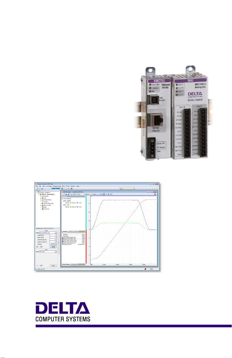
RMC70 MOTION CONTROLLER
STARTUP
GUIDE
With wiring diagrams
Page 2

RMC70 Startup Guide
Where to Get Help
Vid e o Tut orials
In RMCTools, on the Help menu, click Video Tutorials.
RMC T ools Help
In RMCTools, on the Help menu, click Help Topics.
For um
forum.deltamotion.com
Del ta Tec hnical Suppo rt
Phone: +1-360-254-8688
Email: support@deltamotion.com
deltamotion.com ii
Page 3

Contents
Contents
Step 1: Add Expansion Modules .................................... 2
Step 2: Mounting ............................................................. 3
Step 3: Wiring ................................................................. 4
Step 4: Install RMCTools ................................................ 5
Step 5: Connect RMC to PC ........................................... 6
Step 6: Start a New Project ............................................ 7
Step 7: Define the Axes ................................................ 11
Step 8: Test an Actuator ............................................... 13
Step 9: Connect Feedback Device ............................... 16
Step 10: Scale and Offset ............................................. 20
Step 11: Set the Output Polarity ................................... 21
Step 12: Tuning ............................................................ 22
Continuing the Motion Application ................................ 24
Diagnostic Tools ........................................................... 26
Appendix A: Wiring ....................................................... 27
Appendix B: Mounting Dimensions ............................... 42
Appendix C: Agency Compliance ................................. 44
Version 3.03, June 28, 2013
Copyright © 2013, Delta Computer Systems, Inc.
deltamotion.com 1
Page 4
RMC70 Startup Guide
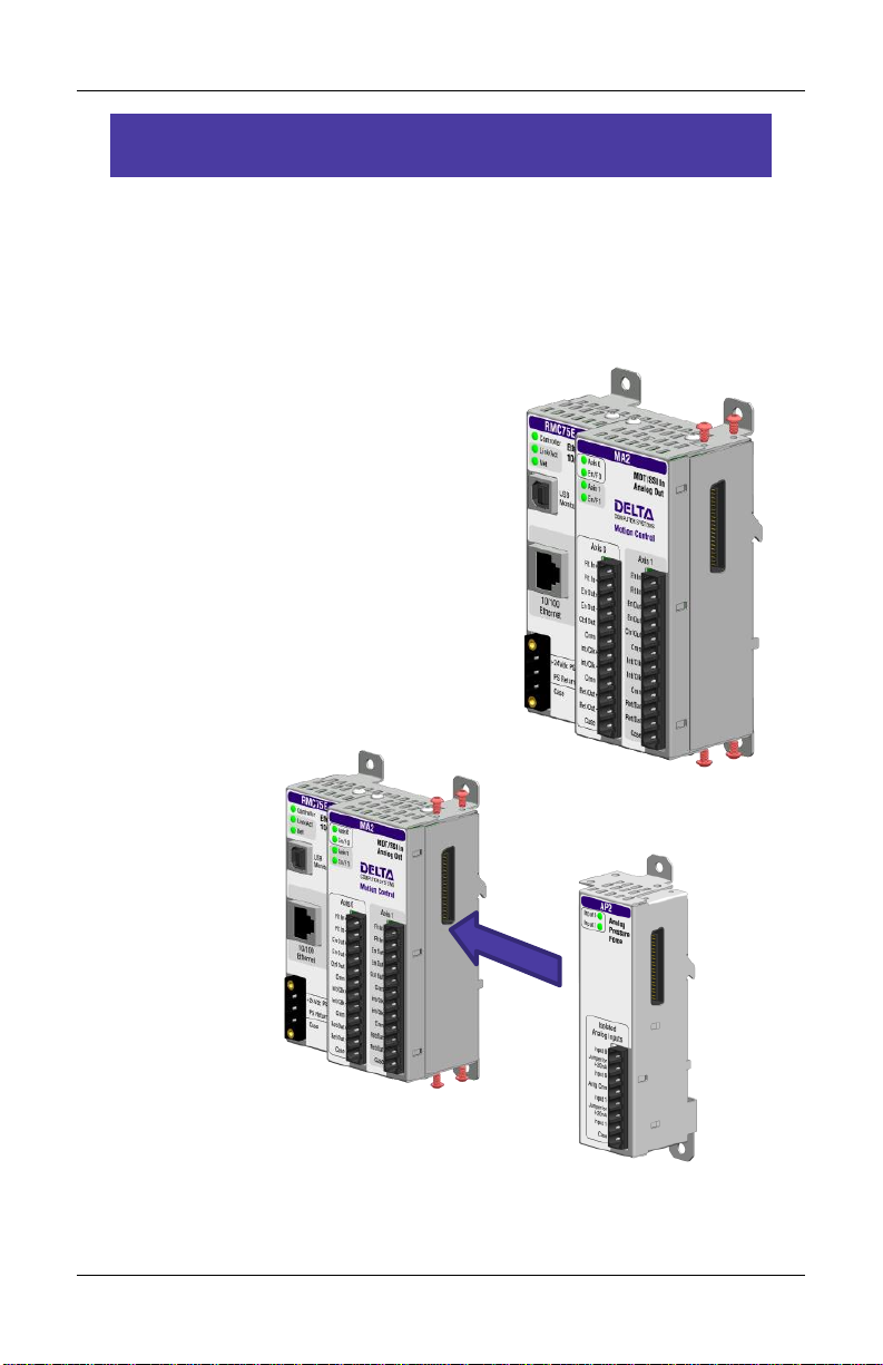
Step 1: Add Expansion Modules
Remove power from the RMC before adding expansion modules.
Instructions are also included with each module.
Expansion modules can be added in any order. Do not add more than
4 expansion modules. No more than two Q2 modules can be installed
per RMC75.
1. Rem ove 4 screws
Remove the 4 phillips-head screws
on the right side of the top and
bottom of the RMC70.
2. Ins tall E xpans i on Module
3. Rei n stall the 4 screws
2 Delta Computer Systems, Inc.
Page 5
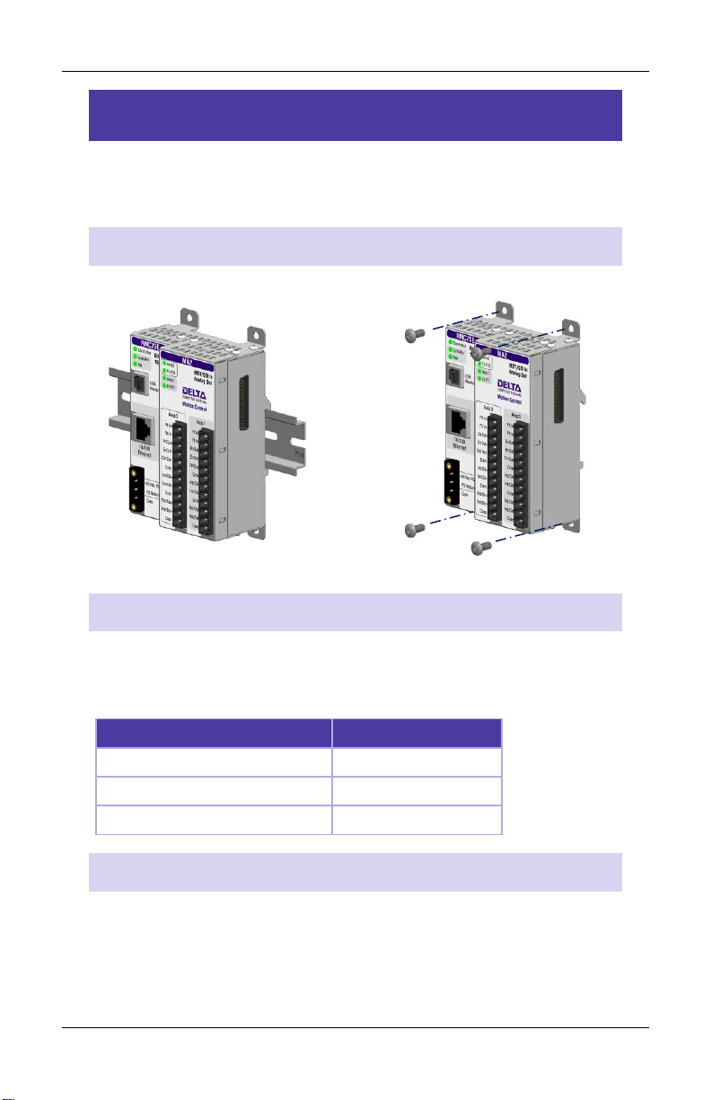
Step 2: Mounting
Ambient Temperature
Clearance
122 - 140°F (50 - 60°C)
3 in. (7.6 cm)
86 - 122°F (30 - 50°C)
2 in. (5.1 cm)
Less than 86°F (30°C)
1 in. (2.5 cm)
Step 2: Mounting
The RMC should be mounted upright on a vertical surface, such that
the ventilation holes are on the top and bottom.
Mou nting Option s
Symmetrical DIN 3 Panel-mount
See Appendix B: Mounting Dimensions for dimensions
Cle a rance
The amount of clearance above and below depends on the maximum
ambient temperature:
Gro u nding
Make sure to properly ground the RMC. If mounted on a DIN rail, the
RMC will conduct to the DIN rail. The RMC shell is electrically
connected to its Case pins.
deltamotion.com 3
Page 6
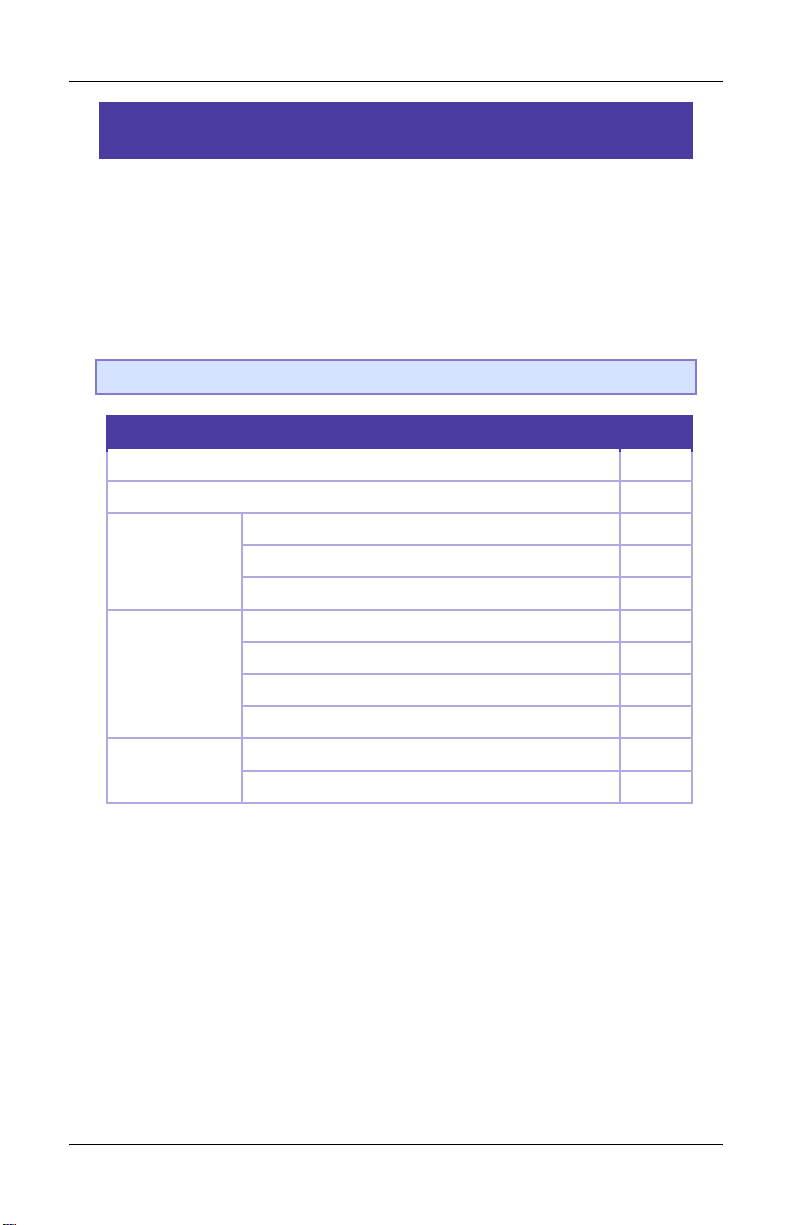
RMC70 Startup Guide
Wiring Topic
Page
General Wiring Information
28
Power
29
MA Modules
Control Output, Enable Output, Fault Input
30
Start/Stop or PWM Transducer
31
SSI Transducer
32
AA Modules
Control Output, Enable Output, Fault Input
30
Voltage Feedback Transducer
36
Potentiometer
37
Current Feedback Transducer
37
QA Modules
Control Output, Enable Output, Fault Input
30
Quadrature Encoder (A, B, Z)
39
Step 3: Wiring
Wire the RMC, actuators and feedback devices according to the
instructions in Appendix A: Wiring.
For expansion module wiring, consult the wiring diagram you received
with it, or use the RMCTools help. For communications wiring, consult
the RMCTools help.
Note: Remove power from the RMC before connecting any wires.
4 Delta Computer Systems, Inc.
Page 7

Step 4: Install RMCTools
PC Requirements
Operating System*
Windows® XP/Vista/7/8
Memory
Minimum OS requirement
Hard Disk Space
20MB of available hard disk space
Display
1024x768 resolution with 16-bit color or
better
Accessories
Mouse or pointing device
Step 4: Install RMCTools
Fro m CD
1. Insert the CD and wait for the splash screen to appear.
2. Click Install RMCTools and follow the instructions. If the splash
screen does not automatically open, run the autorun.exe file.
Dow nload
1. Go to http://www.deltamotion.com/dloads/
2. Choose the RMC70 or RMC150 category, then choose the
Software category.
3. Choose the RMCTools 32-bit or 64-bit version as required for your
computer.
4. Run the rmctoolsinstall32.exe or rmctoolsinstall64.exe file and
follow the instructions.
Sta rt RMCTools
On the Windows Start menu, choose All Programs and then
RMCTools.
*Windows XP requires Service Pack 2 or newer. Versions 3.37.1 (June 2010) and older
support Windows 2000 and Windows XP without SP2.
deltamotion.com 5
Page 8

RMC70 Startup Guide
Step 5: Connect RMC to PC
RMC 75E
USB Cable
Connect a standard A to B USB cable to the PC and to the RMC75E
port labeled USB Monitor.
This type of USB cable is used for PC
peripherals such as printers, and is
available at any store that sells electronics.
Or, use Ethernet Cable
Connect an Ethernet cable to the PC and the RMC75E.
The RMC75E supports both straight through and
crossover cables.
RMC 75S or RMC75 P
Connect Serial Cable
Connect a null-modem, DB-9, female-to-female cable to the RMC75
RS-232 Monitor port, and to a serial port on the PC.
If you make your own cable, pins 2 and 3 must be crossed over, and
pin 5 must be straight-through.
6 Delta Computer Systems, Inc.
Page 9
Step 6: Start a New Project
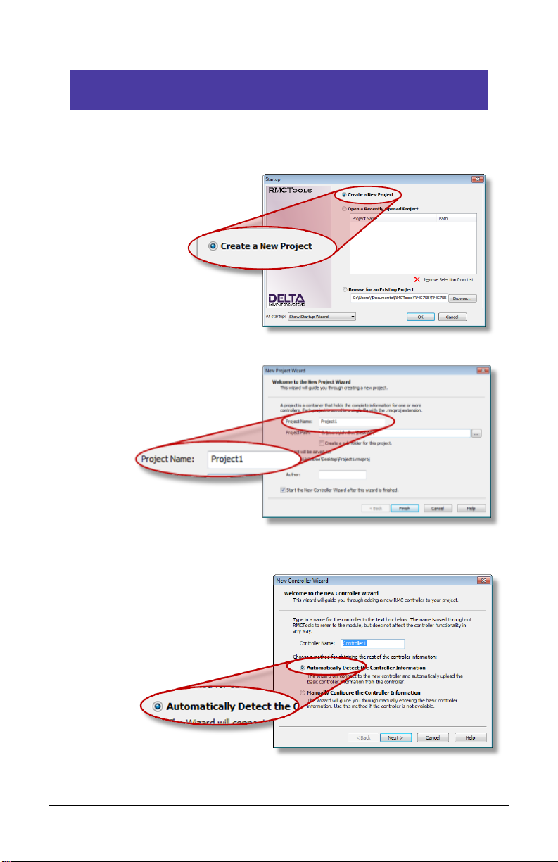
Step 6: Start a New Project
1. Start RMCTools.
2. In the Startup dialog,
choose Create a New
Project and click OK.
3. Enter the Project Name,
then click Finish.
4. In the New Controller
Wizard, choose
Automatically Detect the
Controller Information,
then click Next.
deltamotion.com 7
Page 10
RMC70 Startup Guide
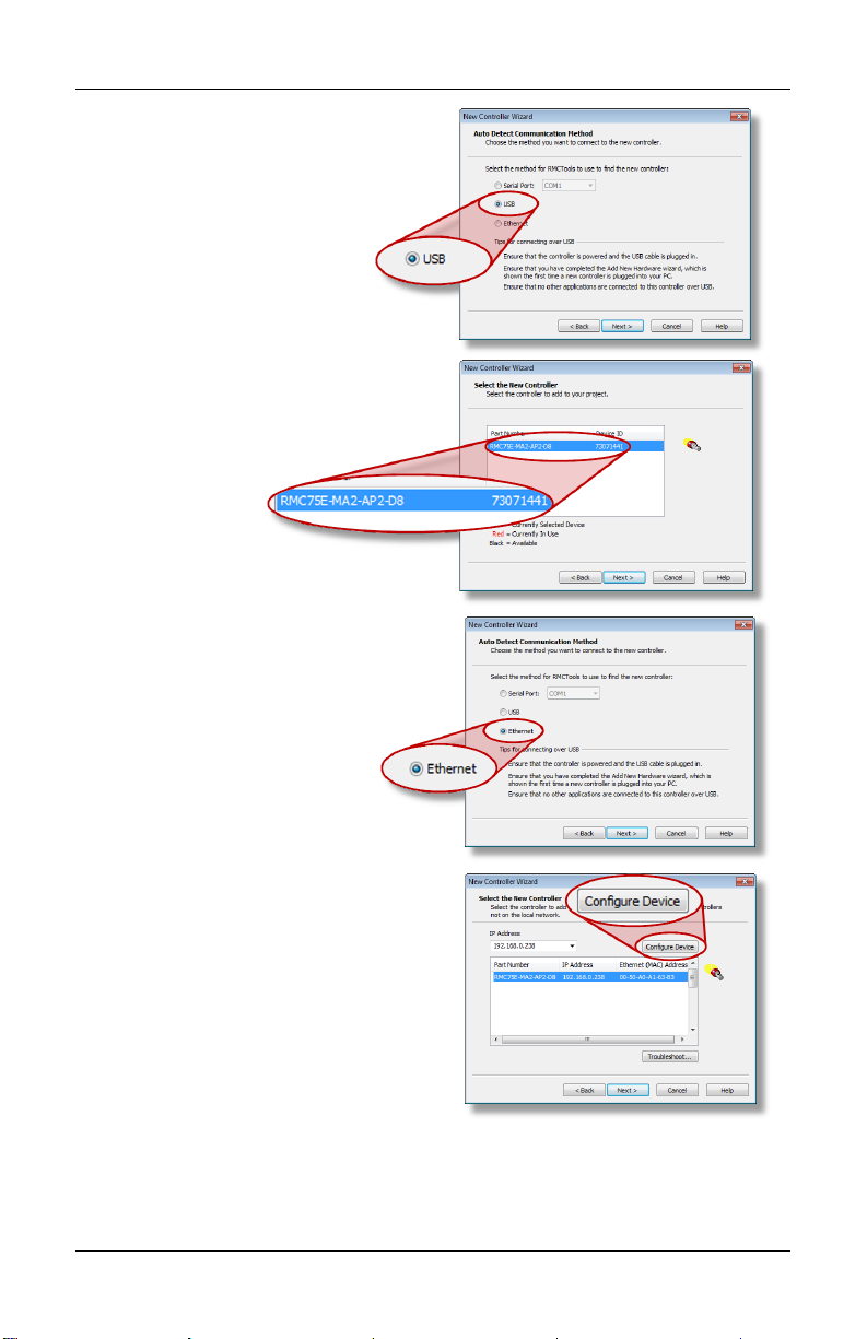
5. RMC75E via USB:
A. Click USB and click Next.
B. When the RMC appears in
the list, choose it and
click Next.
RMC75E via Ethernet:
A. Click Ethernet and click
Next.
B. Use the MAC
address (on the RMC75E
label) to identify the RMC
in the list, then click the
RMC.
C. If the RMC does not have
an IP address (0.0.0.0),
click Configure Device,
choose Use the following
IP address, set the IP
Address and Subnet Mask, then click OK.
D. Click Next.
8 Delta Computer Systems, Inc.
Page 11
Step 6: Start a New Project
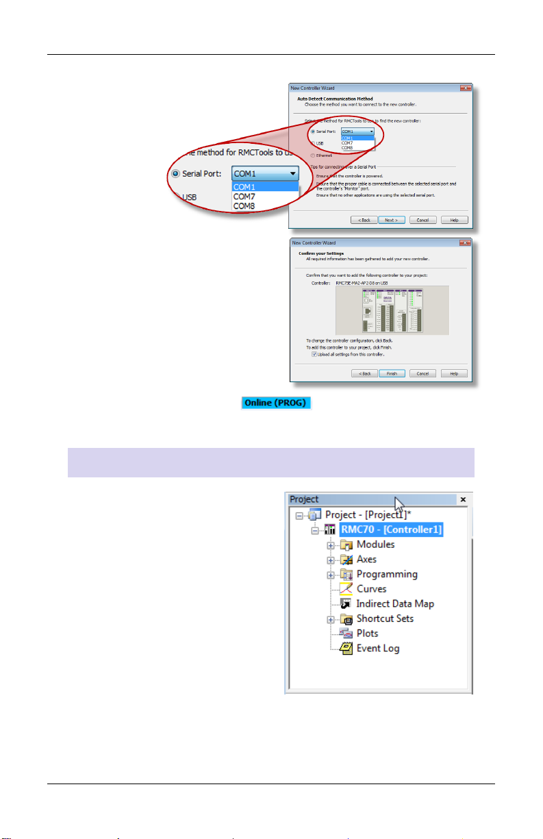
RMC75S or RMC75P:
Select the serial port and click
Next.
6. RMCTools will connect to the
RMC and display it.
Verify it is correct, then click
Finish.
7. The toolbar now displays . This means RMCTools is
communicating with the controller.
Pro j ect P ane
The project pane contains all the
items in the project. Use the
Project pane to navigate through
the entire project.
deltamotion.com 9
Page 12

RMC70 Startup Guide
Sav ing Se ttings
Throughout the startup procedure, make sure to save the
configuration changes you make or they may be lost!
1. Sav e RMCT ools P rojec t
On the File menu, click Save.
2. Upd ate Fl ash
On the Controller menu, click Update Flash.
IF YOU DO NOT UPDATE FLASH, CHANGES TO THE
RMC WILL BE LOST WHEN POWER IS REMOVED!
3. Rep eat Of ten
Make sure to save often to prevent loss of data.
10 Delta Computer Systems, Inc.
Page 13
Step 7: Define the Axes
Control
Output
Position
Feedback
Dual-input Force Feedback
Valve
Hydraulic Cylinder
Analog
Joystick
Position
Feedback
Control
Output
Position
Feedback
Valve
Hydraulic Cylinder
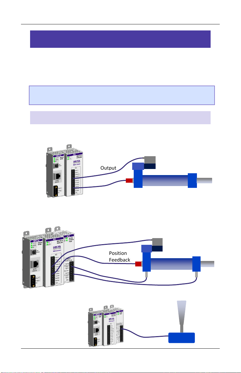
Step 7: Define the Axes
To use a physical input or output, it must be assigned to an internal
software axis. The RMC starts with default axis assignments which you
will likely need to change.
Note: It is important to define the axes at the start of the project.
Major changes to axes later may result in lost axis parameters.
Exa mple A xis De finiti ons
Pos ition Contr o l Axi s
One Control Output, one position input.
Pos ition- F orce C ontrol Axis ( all p art of a si ngle a xis)
One Control Output, one position input, dual-input force
Ref erence Axis
One position input.
deltamotion.com 11
Page 14
RMC70 Startup Guide
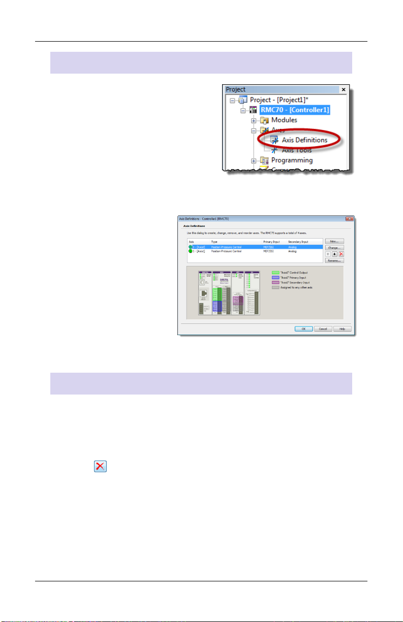
View A xis De f initi o ns
1. In the Project tree, expand the
Axes folder and double-click Axis
Definitions.
2. The Axis Definitions dialog opens:
The list displays the
software axes. To see
the assigned
hardware, click an axis
in the list.
The hardware
assigned to that axis
will be highlighted in
the image.
Edi t Axis Defini tions
Use the Axis Definitions dialog to change the axis definitions:
Click New to add an axis.
Click Change to edit the selected axis.
Click to remove an axis.
If you need to make significant changes to the axis definitions, first
delete all the axes, then create new ones.
For more details, click the Help button.
12 Delta Computer Systems, Inc.
Page 15
Step 8: Test an Actuator
Step 8: Test an Actuator
You will now test an actuator such as a hydraulic valve or a motor. You
will use the Direct Output command to send a voltage to the actuator.
The actuator must already have been wired to the RMC.
1. Check the machine and make sure that the axis may safely move
in both directions.
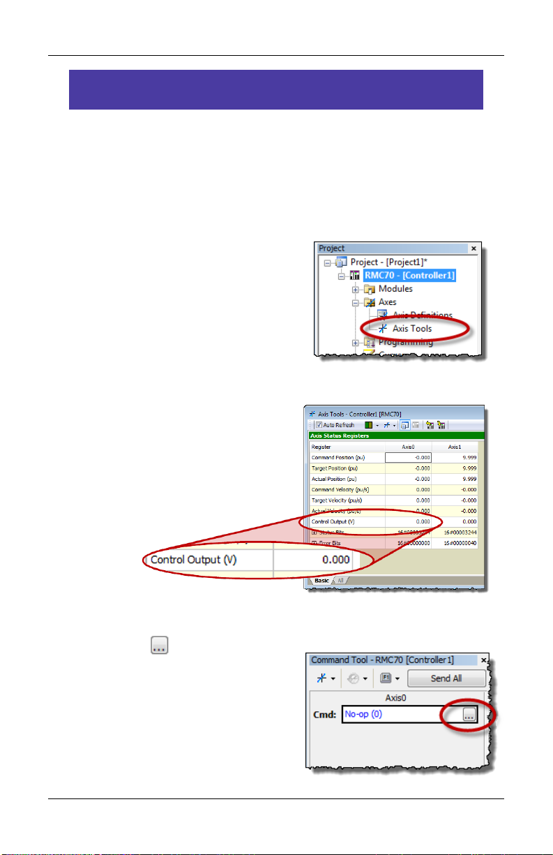
2. In the Project tree, double-click
Axis Tools.
3. In the Axis Status Registers, on
the Basic tab, look at the
Control Output.
It should be 0.
5. In the Command Tool, in the axis the actuator is connected to,
click the button.
deltamotion.com 13
Page 16

RMC70 Startup Guide
6. Browse to Motion Commands,
then Open Loop.
Choose the Direct Output
command and click OK.
7. For the Direct Output command
parameters, enter the following:
Output: 0.1
Ramp Rate: 100
When you send the command in the
next step, the Control Output voltage
will ramp to 0.1 V at a rate of 100
V/sec.
USE THE DIRECT OUTPUT COMMAND WITH CAUTION!
IT DISABLES THE SAFETY FEATURES OF THE RMC!
Fault Controller
Button
If the motion causes problems, be prepared to quickly stop the
axis by clicking the Fault Controller button on the toolbar, or
pressing Ctrl + K on the keyboard.
14 Delta Computer Systems, Inc.
Page 17

Step 8: Test an Actuator
8. In the Command Tool, click Send.
The axis should move, and the Control
Output (in the Axis Status Registers)
should be 0.100.
9. If the axis did not move, resend the command with a larger
Output until the axis moves.
Note: If you are using the Enable Output for enabling the
actuator, such as a motor drive, then you first need to set the
Enable Output before trying to move the actuator. For details,
see the Set Enable Output (67) Command topic in the
RMCTools help.
10. Now stop the axis:
In the Command tool, enter 0 in
the Output box and click Send.
11. Repeat these steps to move the axis in the other direction. In the
Direct Output command, use a negative Output.
Move the axis back and forth through the entire travel range to
make sure the machine is operating properly.
deltamotion.com 15
Page 18

RMC70 Startup Guide
Module
Transducer Type
Page
MA1 or MA2
MDT (Start/Stop or PWM)
17
SSI
17
AA1 or AA2
Analog (±10 V or 4-20 mA)
18
QA1 or QA2
Quadrature (Encoder A, B, Z)
18
AP2 or A2
Analog (±10 V or 4-20 mA)
18
Q1
Quadrature (Encoder A, B, Z)
18
Step 9: Connect Feedback Device
Now that you have connected and tested an actuator, you will connect
and verify a feedback device. The device must already have been
wired to the RMC.
Con figure Feedb ack
In Axis Tools, in the Axis Parameters pane, on the Setup tab, you will
configure certain parameters depending on the type of input you are
using.
Refer to the procedure for your module and transducer type:
16 Delta Computer Systems, Inc.
Page 19

Step 9: Connect Feedback Device
MA M odule – Start/Stop o r PWM
1. In the Axis Parameters, on the
Setup tab, set the Feedback
Type to MDT.
2. Set the MDT Type register to
the type of MDT transducer
you have. This information is
available on the transducer
datasheet.
3. Click the Download button to apply the changes to the RMC.
4. Continue to the Verify Feedback section on page 19.
MA M odule – SSI
1. In the Axis Parameters pane,
on the Setup tab, set the
Feedback Type to SSI.
2. From the information in your
SSI data sheet, set the
following parameters:
SSI Format
SSI Data bits (e.g. 24)
Linear/Rotary
Note: For help on a parameter, click the cell and press F1.
3. Click the Download button to apply the changes to the RMC.
4. Continue to the Verify Feedback section on page 19.
deltamotion.com 17
Page 20

RMC70 Startup Guide
AA Mod ule
1. In the Axis Parameters pane,
on the Setup tab, set the
Input Type to Voltage or
Current.
2. Click the Download button
to apply the changes to the
RMC.
3. Continue to the Verify Feedback section on page 19.
A2 o r AP2 Mo dule
1. In the Axis Parameters pane, on the Setup tab, set the Input Type
to Voltage or Current.
If the input is the primary input of the axis, the Input Type is
under the Primary Control Setup section in the Axis Parameters.
For secondary pressure or force inputs on a dual-loop axis, the
Input Type is under the Secondary Control Setup section in the
Axis Parameters.
2. Click the Download button to apply the changes to the RMC.
3. Continue to the Verify Feedback section on page 19.
QA or Q1 Mo dule
The QA and Q1 module do not require any configuration.
1. Continue to the Verify Feedback section on page 19.
18 Delta Computer Systems, Inc.
Page 21

Step 9: Connect Feedback Device
Ver ify Fe edback
1. In the Axis Status Registers
pane, on the All tab, expand
the Feedback section.
For secondary inputs, expand
the Pressure/Force/Accel
Feedback section.
2. Look at the Counts register (for analog feedback, look at Volts or
Current).
It may be changing slightly.
3. Use the Direct Output command to move the axis back and forth
(as described in the Testing an Actuator section).
4. As the axis moves, look for a corresponding change in the Counts,
Volts or Current. If it does not change smoothly, recheck the
wiring, verify that the parameters on the Setup tab are correct,
and check for smoothly changing Counts, Volts or Current again.
5. Save the project and update Flash.
deltamotion.com 19
Page 22

RMC70 Startup Guide
Step 10: Scale and Offset
The Scale and Offset parameters convert the Counts, Volts or Current
from the transducer into meaningful measurement units, such as
inches, millimeters, pounds, Newtons, etc. RMCTools provides
Scale/Offset wizards to help you calculate these parameters.
Before starting, determine approximately what the positions should
be at either end of travel. This will help you verify later that you
performed the Scaling and Offset procedure correctly.
To s et th e Scal e and Offse t :
1. Go to the Axes Parameters
pane, Setup tab, Tools and
Wizards section.
2. Click Launch in the desired
axis.
3. In the wizard, follow the directions. For help, press the Help
button.
4. After completing the wizard, click the Download button to
apply the changes to the RMC.
5. Remember to save your project and update Flash.
Tip: If the wizard does not work for your system, you can manually
determine the Scale and Offset parameters. See the Scaling topic
in the RMCTools help for details.
20 Delta Computer Systems, Inc.
Page 23

Step 11: Set the Output Polarity
Step 11: Set the Output Polarity
The Actual Position, Pressure, Force or Velocity must increase when
the RMC applies a positive output voltage. If this condition is not met,
you will not be able to perform closed-loop control.
1. Send the Direct Output command with a positive Output value
that is large enough to move the axis.
2. On the Basic tab of the Axis Status Registers pane, observe the
Actual Position and note whether it is increasing or decreasing:
Increasing
The Output Polarity is correct. Go to Enable the Axes below.
Decreasing
You must invert the Output Polarity:
A. In the Axis Parameters pane, on the Setup tab, double-click
the Invert Output Polarity parameter to set it.
B. Click the Download button to apply the change to the
RMC.
Ena ble th e Axes
In order to send motion commands other than Direct Output, the axes
must be enabled after the RMC starts up.
1. In the Command Tool, in the Cmd box,
type Enable, and choose Enable
Controller (7) from the list.
2. Click Send. All axes will be enabled.
Entering RUN Mode will also enable the
axes.
deltamotion.com 21
Page 24

RMC70 Startup Guide
Step 12: Tuning
In order to control an axis in closed-loop, it must first be tuned. You
can use autotuning or manually tune the axis.
Aut otunin g – Pos ition Axes Only
Autotuning can be used for most position control axes.
1. Open Tuning Tools
On the Tools menu, click
Tuning Tools.
2. Set Up Tuning Tools
Set up the buttons that you will use to
move the axis back and forth after
autotuning is complete.
Click the first button labeled
[Click to set up].
Enter a Move Absolute
command with position, speeds,
and acceleration values that will
work for your system.
Repeat for the other button, with
a different position.
3. Start the Tuning Wizard
In the Tuning Tools, click Tuning
Wizard.
4. Complete the Autotuning Wizard
During the autotuning, the wizard will
move the axis a short distance when you prompt it to.
22 Delta Computer Systems, Inc.
Page 25

Step 12: Tuning
5. When the wizard is complete, the Gain Calculator will open. Use
the slider bar to choose gains. Begin by pulling the slider close to
the bottom, then click Apply Gains.
6. Use the buttons you previously set up to move the axis back and
forth. The plot will automatically be displayed.
Tip: To halt the axis, click the Fault Controller button on the
toolbar, or press Ctrl+K.
7. If the Actual Position is not following the Target Position very well,
pull the slider bar up, apply gains, and move the axis again.
Repeat until the Actual Position tracks the Target Position very
well.
Man ual Tu ning–Po sitio n, Pre ssure, or Fo rce A x es
You can manually tune systems for which autotuning does not work.
For instructions:
1. On the help menu, choose Help Topics.
2. On the Index tab, type tuning and double-click about.
3. The Tuning Overview topic describes tuning.
In the Manual Tuning section, choose a procedure. For most
position control applications, choose Tuning a Hydraulic Position
Axis or Motor in Velocity Mode. For pressure or force, choose the
procedure that applies to your axis.
After tuning, save the project and update Flash.
deltamotion.com 23
Page 26

RMC70 Startup Guide
Continuing the Motion Application
After setting up and tuning the RMC, it is ready to perform motion and
be integrated into the rest of your application. The RMC has numerous
features to assist you. The major components are listed here to guide
you when continuing your motion application.
Com m ands
The RMC has a rich set of pre-programmed commands that perform
anything from simple moves to complex motion to system control. For
a list of all the commands, see the Command List topic in the
RMCTools help.
Use r Prog rams
A User Program carries out simple or advanced sequences of
commands on the RMC. This allows the RMC to respond to events
within its control-loop time rather than the scan rate of a PLC or other
host controller. It also reduces the PLC programming required.
A User Program consists of multiple steps linked together in
sequences. Each step can issue any RMC command to one or several
axes. The link types allow branching and looping, waiting for
conditions and many other features. Simple and complex
mathematical operations are also possible in the user program.
A User Program runs on a task. Each task can run one user program at
a time. The RMC70 has four tasks. Therefore, an RMC70 controller
may run up to four User Programs simultaneously.
For details on creating and running User Programs, see the User
Programs topic in the help.
24 Delta Computer Systems, Inc.
Page 27

Continuing the Motion Application
Com m unica tions
Most PLCs or other host controllers can communicate with the RMC,
which includes reading status, writing values, and sending commands.
The RMC70 supports Ethernet, PROFIBUS-DP, or serial RS-232/485.
See the Communications section of the RMCTools help for more
detailed information.
Dis crete I/O
Discrete I/O augments the communications of the RMC. Discrete I/O is
often faster than the communications, and is therefore well-suited for
starting a sequence in the RMC at a specific time. Up to 32 discrete I/O
can be added to the RMC70. Each I/O point is individually configurable
in software as inputs or outputs. See the Discrete I/O topic in the
RMCTools help for details.
Var iables
Variables make the User Programs very flexible and easy to maintain.
Variables can be used to effortlessly change programs and easily
modify User Program parameters via a PLC. Variables can also be used
to store data. For more details see the Variables topic in the help.
Progr a m Tri ggers
Use the Program Triggers to start User Programs based on conditions
defined by the user. For example,
Start a User Program by writing to an RMC variable from a PLC.
Start a User Program when a discrete input turns on.
Automatically start a User Program when the RMC starts up.
When an error condition occurs, automatically start a User
Program to handle it.
See the Program Triggers topic in the RMCTools help for details.
deltamotion.com 25
Page 28

RMC70 Startup Guide
Diagnostic Tools
This section describes the main diagnostic tools of RMCTools that will
aid you in monitoring and troubleshooting your system.
Plo ts
The RMC provides very flexible plotting capabilities. Virtually any
register in the RMC can be plotted, and multiple registers may be
plotted simultaneously. You can easily capture events with the plot
trigger. For details on using plots, see the Plots topics in the help.
Eve n t Log
The Event Log Monitor displays all events that have occurred in the
controller, such as issued commands, changed parameters and errors.
The Event Log Monitor is an important aid in troubleshooting.
The Event Log can help you:
Determine if a command was successfully issued. The entire
command, with parameters, is displayed.
Find out which, if any, error occurred.
See where a command was issued from, for example, from a PLC,
from a User Program or from the Command Tool.
To open the Event Log:
In the Project Pane, expand the controller, and double-click Event
Log .
Note: The Event Log is very useful! When you don’t know what
happened, or why something did not happen, look at the
Event Log.
26 Delta Computer Systems, Inc.
Page 29

Appendix A: Wiring
Wiring Topic
Page
General Wiring Information
28
Power
29
MA Modules
Control Output, Enable Output, Fault Input
30
Start/Stop or PWM Transducer
31
SSI Transducer
32
AA Modules
Control Output, Enable Output, Fault Input
30
Voltage Feedback Transducer
36
Potentiometer
37
Current Feedback Transducer
37
QA Modules
Control Output, Enable Output, Fault Input
30
Quadrature Encoder (A, B, Z)
39
Appendix A: Wiring
This appendix describes how to wire the RMC. Use the table below to
find the wiring diagram you need. For expansion module wiring,
consult the wiring diagram you received with it, or use the RMCTools
help. For communications wiring, consult the RMCTools help.
Note: Remove power from the RMC before connecting any wires.
deltamotion.com 27
Page 30

RMC70 Startup Guide
Gen eral W iring Inform ation
For CE compliance and to minimize electrical interference:
Use twisted pairs for all wiring where possible.
Use shielded cables for all wiring.
Keep RMC wiring separate from AC mains or conductors carrying
high currents, especially high frequency switching power such as
conductors between servo drives and motors or amplifiers and
proportional valves.
For UL and CUL compliance:
Power supply must be Class 2.
All RMC inputs and outputs must be connected to Class 2 circuits
only.
Ter m inal Block Wire C lamp S crew Torque
Tighten the wire clamp screws on the terminal blocks to 7 lb-in (0.8
Nm).
28 Delta Computer Systems, Inc.
Page 31

Appendix A: Wiring
RMC75E or RMC75PPower Supply
+24 VDC
Cmn
Protective Earth
Ground
+24 Vdc PS
PS Return
Case
AC
Line
RMC75SPower Supply
+24 VDC
Cmn
Protective Earth
Ground
Case
+24 Vdc PS
PS Return
AC
Line
Wir ing Po wer
Voltage: +24VDC ( 21.6 – 26.4VDC)
Current rating: Minimum 500 mA
UL and CU L Requi rement s
For UL and C-UL compliance, the power supply must be Class 2. Class 2
power supplies are limited to 100W output. No additional fusing is
required if a class 2 power supply is used.
RMC 75E and RMC7 5 P
RMC 75S
Tighten the wire clamp screws on the terminal blocks to 7 lb-in (0.8
Nm).
deltamotion.com 29
Page 32

RMC70 Startup Guide
Drive or Amplifier
Axis
Connector
Flt In+
Flt In-
En Out+
En Out-
Ctrl Out
Cmn
Case
Shield
+VCC (12-24 VDC)
Enable or Inhibit
+ Ref In
- Ref In
Cmn
To machine common
Apply 12-24 VDC across
input to turn on
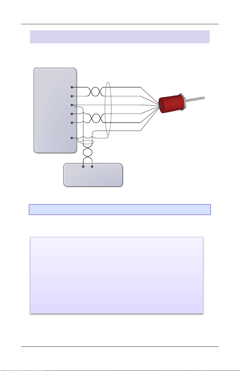
Fault Input:
The Fault Input is optional.
The Fault Input turns on when a current flows. The polarity is
unimportant.
The behavior can be set to Active High or Active Low via
RMCTools.
Enable Output:
The Enable Output is optional. It can be wired to the enable
input of the drive or amplifier.
The Enable Output is a Solid State Relay (SSR) rated for a
maximum of 100 mA and 30V. Both + and - must be connected.
The polarity is unimportant.
The behavior can be set to Active Open or Active Closed via
RMCTools.
Wir ing for all A xis Modules
Con trol O utput, Enable Outp ut, a nd Fau lt Inp ut
30 Delta Computer Systems, Inc.
Page 33
Appendix A: Wiring
12-pin Axis
Connector
Interrogate +
Interrogate -
Return +
Return -
Power Supply
+Pwr
Cmn
Int/Clk+
Int/Clk-
Cmn
Ret/Dat+
Ret/Dat-
Case
Pwr+
DC Ground
Notes:
The MA module interfaces to 5V differential (RS-422) signals.
Single-ended (TTL) transducers are not supported.
The Cmn pins on the 12-pin connector are electrically identical.
The user must supply power to the transducer.
Do NOT connect the transducer ground or common to the
shield, case, or protective earth ground.
MA M odule Start/S top or PWM Tr ansduc er Wir ing
For magnetostrictive transducers with Start/Stop or PWM outputs.
Tip: See next page for manufacturer-specific wiring diagrams.
deltamotion.com 31
Page 34

RMC70 Startup Guide
12-pin Axis
Connector
Interrogate + Input
Interrogate - Input
Pulse + Output
Pulse - Output
+PwrCmn
Int/Clk+
Int/Clk-
Cmn
Ret/Dat+
Ret/Dat-
Case
Pwr+
GND
Yellow
Pink
Gray
Green
Brown
Blue
White
GND
White wire must remain unconnected.
12-pin Axis
Connector
(+) Interrogation or Start
(-) Interrogation or Start
(+) Gate or (+) Stop
+Pwr
Cmn
Int/Clk+
Int/Clk-
Cmn
Ret/Dat+
Ret/Dat-
Case
Customer Supplied Power (+Vdc)
DC Ground
Yellow
Green
Pink
Gray
Red or Brn
White
(-) Gate or (-) Stop
12-pin
Connector
(+) Interrogation
(-) Interrogation
(+) Gate Out, (+) Start/Stop
+Pwr
Cmn
Int/Clk+
Int/Clk-
Cmn
Ret/Dat+
Ret/Dat-
Case
+ VDC
DC Ground
Yellow
Green
Pink
Gray
Red
White
(-) Gate Out, (-) Start/Stop
or
or
or
or
or
or
Wh/Gy
Gy/Wh
Or/Wh
Wh/Or
Wh/Gr
Wh/Bu
- VDC
Frame
-Pwr
Blue
or Gr/Wh
Brown
or Bu/Wh
Man ufactu rer-Spe cific W iring Label s and Color s
Follow all wiring instructions on p.31.
Balluff Micropulse BTL-5, digital RS-485 output
Styles: Z, W, K, E, P, R, AT
MTS Temposonics with digital output (Start/Stop or PWM)
Models: LH, LS, LD, LF, LPS, LPR, G, EP2, ER
MTS Temposonics II with DPM or RPM personality module
32 Delta Computer Systems, Inc.
Page 35

Appendix A: Wiring
12-pin Axis
Connector
Clock+
Clock-
Data+
Data-
Power Supply
+Pwr
Cmn
Int/Clk+
Int/Clk-
Cmn
Ret/Dat+
Ret/Dat-
Case
Pwr+
DC Ground
Notes:
The Cmn pins on the 12-pin connector are electrically identical.
The user must supply power to the transducer.
Do NOT connect the transducer ground or common to the
shield, case, or protective earth ground.
MA M odule SSI T ransdu cer Wi ring
For Synchronous Serial Interface (SSI) transducers and encoders. For
linear SSI transducers, make sure to choose the synchronized type.
Tip: See next page for manufacturer-specific wiring diagrams.
deltamotion.com 33
Page 36

RMC70 Startup Guide
12-pin Axis
Connector
+ Clk
- Clk
+Data
-Data
+PwrCmn
Int/Clk+
Int/Clk-
Cmn
Ret/Dat+
Ret/Dat-
Case
+24 V
GND
Yellow
Pink
Gray
Green
Brown
Blue
12-pin Axis
Connector
(+) Clock
(-) Clock
(+) Data
+PwrCmn
Int/Clk+
Int/Clk-
Cmn
Ret/Dat+
Ret/Dat-
Case
+24 Vdc, Customer Supplied
DC Ground
Yellow
Green
Pink
Gray
Red or Brn
White
(-) Data
Man ufactu rer-Spe cific Wiring Labe ls and Color s
These diagrams provide only transducer manufacturer labels and
colors. Follow all wiring instructions on p.33
Balluff Micropulse BTL-5 with SSI output
Styles: Z, W, K, P
MTS Temposonics with SSI output
Models: R, RP, RH
34 Delta Computer Systems, Inc.
Page 37

Appendix A: Wiring
Pin
Function
Flt In +
Fault Input
Flt In -
Fault Input
En Out +
Enable Output
En Out -
Enable Output
Ctrl Out
Control Output, ± 10 V 16-bit Analog
Cmn
Common
MDT Transducer
SSI Transducer
Int/Clk +
+ Interrogation
+ Clock
Int/Clk -
- Interrogation
- Clock
Ret/Dat +
+ Return
+ Data
Ret/Dat -
- Return
- Data
Cmn
Common
Case
RMC Chassis
Notes:
The two Cmn pins are electrically the same.
The user must supply power for the transducer.
MA M odule Pin-ou t
deltamotion.com 35
Page 38

RMC70 Startup Guide
12-pin Axis
Connector
+Analog Out
-Analog Out
Pwr Common
+Pwr
Power Supply
+Pwr
Cmn
+Analog In
Jumper for 4-20 mA
-Analog In
Cmn
+10Vdc Exciter
Case
Signal Common
12-pin Axis
Connector
+Analog Out
Common
Power Supply
+24 VDC
Cmn
+Analog In
Jumper for 4-20 mA
-Analog In
Cmn
+10Vdc Exciter
Case
+Pwr
To reduce electrical interference:
-Analog In and Cmn must be
connected, either internal to the
transducer or externally as close
as possible to the transducer.
Use individually shielded
twisted-pair wire.
Connect cable shield to earth
ground on one end only.
If transducer has only one
common, connect Pwr Supply
Common and RMC Cmn to it. For
best results, make this
connection at the transducer.
AA M odule Voltag e Tran sducer Wiring
Vol tage T ransdu cer, 4 - o r 5-Wi re
Vol tage T ransdu cer, 3 -Wi re
36 Delta Computer Systems, Inc.
Page 39

Appendix A: Wiring
12-pin Axis
Connector
+Analog In
Jumper for 4-20 mA
-Analog In
Cmn
+10Vdc Exciter
Case
Potentiometer
Wiper
12-pin Axis
Connector
+Analog Out
Power Supply
+24 VDC
Cmn
+Analog In
Jumper for 4-20 mA
-Analog In
Cmn
+10Vdc Exciter
Case
+Pwr
To reduce electrical interference:
The connection of -Analog In to Cmn should be
made as close as possible to the transducer.
Use individually shielded twisted-pair wire.
Connect cable shield to ground on one end only.
The Jmpr and -In pins are internally
connected via a 250 Ω resistor.
To reduce noise, use individually
shielded twisted-pair wire.
AA M odule Potent iomet e r with Excit er Pin
Note: When using a potentiometer, use the Exciter pin to increase the
accuracy of the analog to digital conversion.
AA M odule 4-20 m A
deltamotion.com 37
Page 40

RMC70 Startup Guide
Pin
Function
Flt In +
Fault Input
Flt In -
Fault Input
En Out +
Enable Output
En Out -
Enable Output
Ctrl Out
Control Output, ±10 V 16-bit Analog
Cmn
Common
Analog In +
Signal +
Jumper for
4-20 mA
Jumper for Current Transducer
Analog In -
Signal -
Cmn
Common
+10Vdc
Exciter
10 Volt source for potentiometer
Case
RMC Chassis
Notes:
The two Cmn pins are electrically the same.
The user must supply power for the transducer.
AA M odule Pin-ou t
38 Delta Computer Systems, Inc.
Page 41

Appendix A: Wiring
25-pin Axis
Connector
A-
A+
B+
Z-
Power Supply
+Pwr
Cmn
Pin 1: A-
Pin 2: A+
Pin 3: B-
Pin 4: B+
Pin 14: Z-
Cmn
Z+
B-
Pin 15: Z+
25-pin Axis
Connector
Pin 6: RegY/NegLim-
Pin 7: RegY/NegLim+
Pin 8: RegX/PosLim-
Pin 9: RegX/PosLim+
Pin 18: Home-
Pin 19: Home+
Pwr+
Common
Apply 12-24 VDC across input to turn on
Apply 12-24 VDC across input to turn on
Apply 12-24 VDC across input to turn on
Important!
The A, B and Z signals accept
5 V differential (RS-422) signals only!
Reg/Lim and Home Inputs:
Compatible with 12-24 VDC.
Max current draw is 2.7 mA max.
Turn on when the voltage is greater than 6 V. The polarity is
unimportant.
QA M odule Wirin g
See page 40 for the QA module pin-out.
deltamotion.com 39
Page 42

RMC70 Startup Guide
Pin
Label
Function
1
A-
A- from encoder
2
A+
A+ from encoder
3
B-
B- from encoder
4
B+
B+ from encoder
5
n/c
No connection
6
Reg Y/NegLim-
Registration Y or Negative
Limit
7
Reg Y/NegLim+
8
Reg X/PosLim-
Registration X or Positive
Limit
9
Reg X/PosLim+
10
n/c
No connection
11
n/c
No connection
12
Control Out
Control Output
13
Cmn
Common
14
Z-
Index pulse from encoder
15
Z+
16
Cmn
Common
17
n/c
No connection
18
Home-
Home Input
19
Home+
20
FltIn-
Fault Input
21
FltIn+
22
n/c
No connection
23
n/c
No connection
24
EnOut-
Enable Output
25
EnOut+
Notes:
The two Cmn pins are electrically the same.
The user must supply power for the transducer.
QA M odule Pin-ou t
40 Delta Computer Systems, Inc.
Page 43

Appendix A: Wiring
PLC
RMC Module
Input b
Input Common
Power
Output
Input a Output
RMC Module
+VCC (12-24 VDC)
Output
Output
Resistive
Load
…
Output Cmn
RMC Module
+VCC (12-24 VDC)
Output
Output
Resistive
Load
…
Output Cmn
D8 Module Disc r ete I/O Wir i ng
The eight I/O on the D8 expansion module are individually
configurable via software to be inputs or outputs.
Dis crete Output s
The discrete outputs are solid state relays. When off, they have high
impedance, and when on, they have low impedance (50 Ω max, 25 Ω
typical). The maximum current is 75 mA, and the maximum voltage is
30 V.
Outputs can be wired in either a high-side or low-side configuration.
Because all the outputs share a common, all outputs on the same
module must be wired the same.
When switching inductive loads, place a diode or tranzorb across the
load to protect the switch when it turns off. Otherwise, a voltage spike
in excess of the 30 V rating of the SSR may occur. See the D8 Wiring
topic in the RMCTools help for more details.
Dis crete Inputs
The discrete inputs are compatible with 12-24 VDC signals. Because all
the inputs share a common, all inputs on the same module must be
wired the same.
Example
deltamotion.com 41
Page 44

RMC70 Startup Guide
Appendix B: Mounting Dimensions
This sections contains mounting hole dimensions for the RMC75 series
motion controller and expansion modules. Up to four expansion
modules may be added to the right side of the RMC75 base module.
Bas e Modu le
RMC75S, RMC75P, RMC75E
Note: Drawing is not 1:1 scale.
42 Delta Computer Systems, Inc.
Page 45

Appendix B: Mounting Dimensions
Exp ansion Modul es
There are two different expansion module widths.
D8 AP2, A2, Q1
Note: Drawings are not 1:1 scale.
deltamotion.com 43
Page 46

RMC70 Startup Guide
Appendix C: Agency Compliance
CE
For CE compliance and to minimize electrical interference:
Use twisted pairs for all wiring where possible.
Use shielded cables for all wiring.
Keep RMC wiring separate from AC mains or conductors carrying
high currents, especially high frequency switching power such as
conductors between servo drives and motors or amplifiers and
proportional valves.
UL and CU L
For UL and CUL compliance:
Power supply must be Class 2.
All RMC inputs and outputs must be connected to Class 2 circuits
only.
44 Delta Computer Systems, Inc.
Page 47

deltamotion.com 45
Page 48

 Loading...