

Page 1

RMC200 MOTION CONTROLLER
STARTUP
GUIDE
With wiring diagrams
Connect. Control. Optimize.
Page 2

Where to Get Help
Where to Get Help
Video Tutorials
In RMCTools, on the Help menu, click Video Tutorials.
RMCTools Help
In RMCTools, on the Help menu, click Help Topics.
Forum
forum.deltamotion.com
Delta Technical Support
Phone: +1-360-254-8688
support@deltamotion.com
Email:
deltamotion.com ii
Page 3

Important Information
Important Information
Before using the RMC200 motion controller, read this Startup
Guide and relevant manuals carefully.
Installing, putting into service, using, and maintaining the RMC200
must be carried out by suitably trained personnel.
Relevant documentation:
• RMCTools User Manual: provides information on using the
RMC200 motion controller. This information is also provided
in the RMCTools software help topics.
• RMC200 Datasheet: includes full specifications of the
modules.
Maintenance: The RMC200 contains no user-serviceable parts. The
RMC200 should be repaired only by personnel authorized by Delta.
Notices used in this document:
WARNING: Identifies information about circumstances that
can lead to personal injury or death, property damage, or
economic loss.
IMPORTANT: Identifies information that is important for
successfully applying the product.
iii deltamotion.com
Page 4

Important Information
Important Information
WARNING: Using this product in a manner not specified by
the manufacturer may impair the protection provided by the
equipment.
WARNING: Employ safety circuits or devices external to the
motion controller to ensure the machine operates safely even
in the event of a failure in any part of the controller.
WARNING: If deemed necessary by a risk assessment, employ
an emergency stop system to avert harm or to reduce existing
hazards to persons, machinery, or work in progress.
WARNING: Use proper lock-out procedures when working on
the machine to prevent injury or machine damage.
WARNING: On hydraulic systems, use blocking valves or other
suitable methods to prevent the hydraulic system from moving
unexpectedly when working on the machine.
WARNING: Use fuses to limit any fault currents that could
cause smoke or fire due to a fault in the RMC or external
device.
deltamotion.com iv
Page 5

Contents
Contents
Step 1: Mount the Base .................................................. 2
Step 2: Mount the Modules ............................................. 4
Step 3: Wiring ................................................................. 5
Step 4: Install RMCTools ................................................ 6
Step 5: Connect RMC to PC ........................................... 7
Step 6: Start a New Project ............................................ 8
Step 7: Define the Axes ................................................ 13
Step 8: Test each Actuator ........................................... 15
Step 9: Test each Feedback Device............................. 19
Step 10: Scale and Offset ............................................. 23
Step 11: Set the Output Polarity ................................... 24
Step 12: Tuning ............................................................ 25
Continuing the Motion Application ................................ 28
Diagnostic Tools ........................................................... 31
Appendix A: W iring ....................................................... 32
Appendix B: Mounting Dimensions ............................... 51
Appendix C: Agency Compliance ................................. 53
Version 1.04, March 7, 2019
Copyright © 2019, Delta Computer Systems, Inc.
deltamotion.com 1
Page 6

RMC200 Startup Guide
Ambient Temperature
Clearance
122 - 140°F (50 - 60°C)
3 in. (7.6 cm)
Less than 122°F (50°C)
2 in. (5.1 cm)
Operating ambient temperature
-4 to +140°F (-20 to +60°C)
Storage ambient temperature
-40 to +185°F (-40 to +85°C)
Ambient humidity
5-95%, non-condensing
Clearance
Clearance
Step 1: Mount the Base
The RMC base should be mounted upright on a vertical surface, such
that the module ventilation holes are on the top and bottom.
Mounting the Base on a Panel
See Appendix B: Mounting Dimensions for more details
Clearance
The required clearance above and below for airflow
depends on the maximum ambient temperature:
Environment
The environment must conform to the following:
Keep liquids and conductive particles away from the RMC200.
2 Delta Computer Systems, Inc.
Page 7

Step 1: Mount the Base
Enclosure
If the RMC200 is installed in an electronics enclosure, the enclosure
must be large enough to dissipate the power that is being generated
by the components in the cabinet without having the air temperature
in the cabinet exceed the rating on any of the components within the
cabinet.
To ensure sufficient convection, the enclosure should provide the
following clearances:
• At least 2” between front of RMC200 and enclosure
• At least 3” between top of RMC200 and enclosure
• At least 3” plus space for wires between bottom of RMC200
and enclosure
Grounding
IMPORTANT: Make sure to properly ground the base metal.
Mounting via steel screws to a well-grounded surface such as a
metal panel will typically suffice. To ensure a robust
connection, the grounding stud on the bottom of the base may
be used. The Case pins of each module are electrically
connected to the module chassis, which will conduct to the
base chassis.
WARNING: Electrostatic Discharge (ESD): Electrostatic
discharge can cause internal damage and affect normal
operation. When handling this equipment, follow these
guidelines:
• Touch a grounded object to discharge potential static or
wear a grounding wrist strap.
• Do not touch connectors or pins on the module boards, or
electronic components inside the modules.
• Use a static-safe workstation, if possible.
• Store modules in ESD packaging when not in use.
deltamotion.com 3
Page 8

RMC200 Startup Guide
Slot
Compatible Modules
0
PS4D (B5, B7 and B11)
PS6D (B15)
1
CPU40
2+
CA4, CV8, S8, A8, Q4, D24
Hooks
Pins
Connector
Screw
Step 2: Mount the Modules
Module Locations
Modules may only be installed in compatible slots on the base.
Modules are keyed so only compatible modules mount in a given slot.
Install each M odule
1. Tip the module up.
2. Set the upper pins
in the hooks.
3. Rotate the module down
carefully such that the
base connector engages.
4. Tighten the holddown screw
to 5 in-lbs (0.6 Nm).
4 Delta Computer Systems, Inc.
Page 9

Step 3: Wiring
Wiring Topic
Page
General Wiring Information
33
PS4D and PS6D: Power Supply
35
CPU40, CA4, CV8: Discrete I/O
36
CA4, CV8: Control Output ±10V, 4-20 mA, or ±20mA
37
S8: SSI
38
S8: MDT
40
S8: Quadrature Encoder
42
A8: Analog ±10V, 4-20 mA
43
Q4: Quadrature Encoder
46
D24: Discrete I/O
48
Step 3: Wiring
Wire the power, actuators and feedback devices to the RMC according
to the instructions in Appendix A: Wiring on page 32.
IMPORTANT: Remove external power from the device before
wiring. Failure to do so may cause component failure.
deltamotion.com 5
Page 10

RMC200 Startup Guide
PC Requirements for RMCTools
Operating System*
Windows® XP/Vista/7/8/10
Step 4: Install RMCTools
Download
1. Go to http://www.deltamotion.com/dloads/
2. Choose the RMC200 section, then choose the Software section.
3. Choose RMCTools, 32-bit or 64-bit, as required for your computer.
RMCTools supports the RMC70, RMC150 and RMC200 controllers.
4. Run the rmctoolsinstall32.exe or rmctoolsinstall64.exe file and
follow the instructions.
Start RMCTools
On the Windows Start menu, choose All Programs and then
RMCTools.
*Windows XP requires Service Pack 3 or newer.
6 Delta Computer Systems, Inc.
Page 11

Step 5: Connect RMC to PC
Step 5: Connect RMC to PC
USB Cable
Connect an A to B USB cable to the PC and
to the RMC200 USB port.
This type of USB cable is typically used for
PC peripherals such as printers, and is
available at any store that sells electronics.
Or, use Ethernet Cable
Connect an Ethernet cable to the RMC200 and the PC
or Ethernet switch. The RMC200 supports both
straight through and crossover cables.
Setting the IP Address
The IP address need not be set before connecting via Ethernet. If the
PC is on the same physical Ethernet network as the RMC, RMCTools
can detect the RMC even if the IP address is not set.
The RMC’s IP address and subnet mask can be set via RMCTools while
connecting via Ethernet. See the next step Start a New Project for
details.
Or, set the IP address and subnet mask via the CPU display screen:
1. Using the Menu , arrow and Enter buttons, browse to:
Ethernet Change IP Address Set manually
2. Using the arrow buttons, set the IP address.
3. Press Enter for Next and set the subnet mask.
4. Press Enter for Next and use the arrow and Enter
buttons to choose whether to use a default gateway. Set it if so
desired.
deltamotion.com 7
Page 12

RMC200 Startup Guide
Step 6: Start a New Project
1. Start RMCTools.
In the Startup dialog, choose Create a New Project and click OK.
2. Enter the Project Name, then click Finish.
3. In the New Controller Wizard, choose Automatically Detect the
Controller Information, then click Next.
8 Delta Computer Systems, Inc.
Page 13

Step 6: Start a New Project
4. Communication Method:
Via USB:
A. Choose USB and click Next.
B. The RMC200 will appear in the list as R200-CPU40. Choose
the RMC and click Next.
Tip: If multiple controllers are listed, use the serial number to
identify your RMC in the list (Device ID). The serial
number is accessible on the RMC200 display screen:
1. Using the Menu , arrow and Enter
buttons, browse to:
Module InfoSlot 1 (CPU40)
2. The serial number is prefixed by SN:
C. RMCTools will connect to the RMC and display it.
Verify it is correct, then click Finish.
deltamotion.com 9
Page 14

RMC200 Startup Guide
MAC address.
Via Ethernet:
A. Choose Ethernet and click
Next.
B. The RMC200 will appear in the list as R200-CPU40. Click the
RMC and click Next.
Tip: If multiple controllers are listed, use the MAC address to
identify your RMC in the list. The MAC address is
accessible on the RMC200 display screen:
1. Using the Menu , arrow and Enter
buttons, browse to:
Ethernet View IP Address
2. Using the arrow buttons, scroll down to view the
C. If the RMC does not have an IP address (0.0.0.0), you must set
an IP address now in order to connect via Ethernet:
a. Click Configure Device.
10 Delta Computer Systems, Inc.
Page 15

Step 6: Start a New Project
b. Choose Use the following IP address, set the IP Address
and Subnet Mask, then click OK.
Tip: For help on IP addressing, in the RMCTools help, in the Index tab,
type IP Address and choose that item from the list.
D. Click Next. RMCTools will connect to the RMC and display it.
Verify it is correct, then click Finish.
5. The toolbar now displays . This means RMCTools
is communicating with the controller.
Project Pane
The project pane contains all the items in the project. Use the Project
pane to navigate through the entire project.
deltamotion.com 11
Page 16

RMC200 Startup Guide
Saving Settings
Throughout the startup procedure, make sure to save the
configuration changes you make or they may be lost!
1. Save RMCTools Project
On the File menu, click Save.
2. Update Flash
On the Controller menu, click Update Flash.
IMPORTANT: If you do not update Flash, changes to the RMC
will be lost when power is removed!
3. Repeat Often
Make sure to save often to prevent loss of data.
Tip: On the File menu, click Save and Update Flash to perform
both operations at once.
12 Delta Computer Systems, Inc.
Page 17
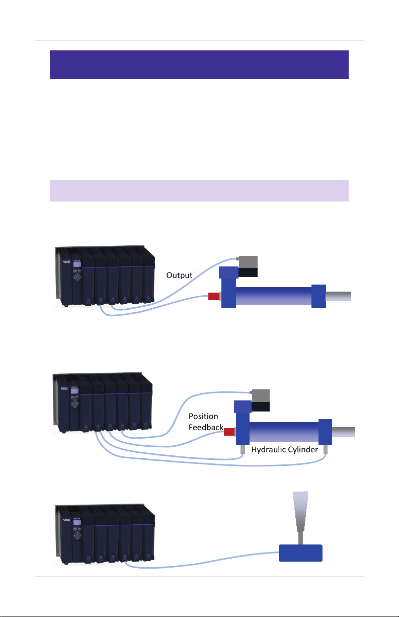
Step 7: Define the Axes
Position
Feedback
Dual-input Force Feedback
Valve
Hydraulic Cylinder
Analog
Position
Control
Output
Position
Feedback
Valve
Hydraulic Cylinder
Control
Output
Step 7: Define the Axes
To use a physical input or output, it must be assigned to an internal
software axis. The RMC starts with default axis assignments which you
will likely need to change.
Make sure to define the axes at the start of the project. Major changes
to axis definitions later may result in lost axis parameters.
Example Axis Definitions
Position Control Axis
One Control Output, one position input.
Position-Force Control Axis (all part of a single axis)
One Control Output, one position input, dual- input force
Reference Axis
One position input.
Feedback
deltamotion.com 13
Joystick
Page 18

RMC200 Startup Guide
View Axis Definitions
1. In the Project tree, expand the
Axes folder and double-click
Axis Definitions.
2. The Axis Definitions dialog opens:
The list displays the
software axes. To see the
assigned hardware, click
an axis in the list.
The hardware assigned to
that axis will be
highlighted in the image.
Edit Axis Definitions
Use the Axis Definitions dialog to change the axis definitions:
• Click New to add an axis.
• Click Change to edit the selected axis.
• Click to remove an axis.
If you need to make significant changes to the axis definitions, first
delete all the axes, then create new ones.
For more details, click the Help button.
After changing axis definitions, save the project and update Flash.
14 Delta Computer Systems, Inc.
Page 19

Step 8: Test each Actuator
Step 8: Test each Actuator
You will now test an actuator such as a hydraulic valve or a motor. You
will use the Direct Output command to send a command signal to the
actuator. The actuator must already have been wired to the RMC.
Set the Output Type
1. In the Project tree,
double-click Axis Tools.
2. In the Axis Parameters, on the Setup tab, set the Output Type to
the correct setting for your actuator. Typically, it will be ±10V.
3. Click the Download button
to apply the changes to
the RMC.
4. In the Axis Status Registers, on the
Basic tab, look at the Control
Output.
It should be 0.
Notice that the Final Output shows
the output value in Volts or mA.
deltamotion.com 15
Page 20

RMC200 Startup Guide
Enable the Axis – Enable Controller (7) Command
5. In the Command Tool, in the axis
the actuator is connected to, click
the button.
6. Browse to General Commands,
click Enable Controller, then
click OK.
The Enable Controller command
enables all the axes to motion
commands can be sent to them.
7. In the Command Tool, click Send.
The axes will now be enabled, as
indicated by the Enabled Status bit
in the Axis Status Registers.
16 Delta Computer Systems, Inc.
Page 21

Step 8: Test each Actuator
Move the Axis - Direct Output (9) Command
WARNING: Use the Direct Output (9) command with caution. It
disables the Autostop features of the axis.
Fault Controller Button
In the next steps, if you need to quickly stop the axis, click the
Fault Controller button on the toolbar, or press Ctrl + K on the
keyboard.
8. Browse to Motion Commands, then
Open Loop.
Choose the Direct Output
command and click OK.
The Direct Output command is
useful for setup because it ignores
all axis errors.
9. For the Direct Output command parameters, enter the following:
• Output (%): 10
• Ramp Rate: 1000
When you send the command in
the next step, the Control Output
will ramp to 10 % output at a rate
of 1000 %/sec.
deltamotion.com 17
Page 22

RMC200 Startup Guide
10. In the Command Tool, click Send.
The axis should move, and the
Control Output (in the Axis Status
Registers) should be 10.0.
11. If the axis did not move, resend the command with a larger
Output until the axis moves.
Note: If the Enable Output is wired to the actuator, before
moving, set it with the Set Enable Output command.
12. Now stop the axis:
In the Command tool, enter 0
in the Output box and click
Send.
13. Repeat these steps to move the axis in the other direction. In the
Direct Output command, use a negative Output value.
Move the axis back and forth through the entire travel range to
make sure the axis is moving properly.
18 Delta Computer Systems, Inc.
Page 23

Step 9: Test each Feedback Device
Transducer Type
Module
Page
SSI
S8
20
Start/Stop or PWM (Magnetostrictive)
S8
20
Quadrature Encoder
Q4, S8, D24
21
Analog (Voltage or Current)
A8
21
Step 9: Test each Feedback Device
Now that you have connected and tested an actuator, you will verify a
feedback device. The device must already have been wired to the
RMC.
Configure Feedback
In Axis Tools, in the Axis Parameters pane, on the Setup tab, you will
configure certain parameters depending on the type of input you are
using.
Refer to the procedure for your transducer type and module:
deltamotion.com 19
Page 24

RMC200 Startup Guide
SSI Feedback
1. In the Axis Parameters pane, on the Setup tab, set the Feedback
Type to SSI.
2. Set the following parameters:
• SSI Format
• SSI Data bits (e.g. 24)
• Linear/Rotary
Choose Format and Data Bits per the SSI device data sheet.
For linear transducers, choose Linear. For rotary encoders, choose
Rotary if the axis on your machine can rotate continuously and
the positions wrap around, or Linear if it has a limited travel range
and the encoder will not cross the zero counts point.
Note: For help on a parameter, click the cell and press F1.
3. Click the Download button to apply the changes to the RMC.
4. Continue to the Verify Feedback section on page 22.
Start/Stop or PWM (Magnetostrictive) Feedback
1. In the Axis Parameters, on the Setup tab, set the Feedback Type
to MDT.
2. Set MDT Type to the type of
magnetostrictive transducer
you have.
This information is available
from your transducer
datasheet.
3. Click the Download button to apply the changes to the RMC.
4. Continue to the Verify Feedback section on page 22.
20 Delta Computer Systems, Inc.
Page 25

Step 9: Test each Feedback Device
Analog Feedback
1. In the Axis Parameters, on the
Setup tab, set the Analog Input
Type to Voltage (±10V) or Current
(4-20mA).
If the input is the primary input of
the axis, the Input Type is under the Primary Control Setup
section in the Axis Parameters.
For pressure or force inputs on a dual-loop axis, the Input Type is
in the Secondary Control Setup section in the Axis Parameters.
2. Click the Download button to apply the changes to the RMC.
3. Continue to the Verify Feedback section on page 22.
Quadrature Feedback
1. In the Axis Parameters, on the
Setup tab, set the Linear/Rotary
parameter.
For linear transducers, choose
Linear. For rotary encoders, choose
Rotary if the axis on your machine
can rotate continuously and the
positions wrap around, or Linear if it has a limited travel range
and the encoder will not cross the zero counts point.
2. Click the Download button to apply any changes to the RMC.
3. Continue to the Verify Feedback section on page 22.
deltamotion.com 21
Page 26

RMC200 Startup Guide
Verify Feedback
1. In the Axis Status Registers pane,
on the All tab, expand the Feedback
section.
For secondary inputs, expand the
Pressure/Force/Accel Feedback
section.
2. Depending on your feedback type, look at the Counts, Volts or
Current register. It may be changing slightly.
3. Use the Direct Output command to move the axis back and forth
(as described in the Test an Actuator section).
4. As the axis moves, look for a corresponding change in the Counts,
Voltage or Current. If it does not change smoothly, recheck the
wiring, verify that the parameters on the Setup tab are correct,
and check for smoothly changing Counts, Voltage or Current
again.
5. Save the project and update Flash.
22 Delta Computer Systems, Inc.
Page 27

Step 10: Scale and Offset
Step 10: Scale and Offset
The Scale and Offset parameters convert the Counts, Volts or Current
from the transducer into meaningful measurement units.
First, determine the approximate positions at either end of travel. This
will help you verify later that you performed the procedure correctly.
To set the Scale and Offset:
1. Go to the Axes Parameters pane,
Setup tab, Tools and Wizards
section.
2. Click Launch for the Scale/Offset
Wizard in the desired axis.
3. In the wizard, follow the directions. For help, press the Help
button.
Tip: If the wizard does not work for your system, you can manually
determine the Scale and Offset parameters. See the Scaling topic
in the RMCTools help for details.
4. After completing the wizard, in
the Axis Parameters, locate the
Display Units parameter.
Select the desired display units.
If you wish to use units that are
not listed, choose Custom, then
type up to 4 characters in the Custom Units parameter.
5. Click the Download button to apply the changes to the RMC.
Remember to save your project and update Flash.
deltamotion.com 23
Page 28

RMC200 Startup Guide
Step 11: Set the Output Polarity
The Actual Position, Pressure, Force or Velocity must increase when
the RMC applies a positive Control Output percentage. If this condition
is not met, you will not be able to perform closed-loop control.
1. Send the Direct Output command with a positive Output value
that is large enough to move the axis.
2. On the Basic tab of the Axis Status Registers pane, observe the
Actual Position and note whether it is increasing or decreasing:
Increasing
The Output Polarity is correct. Go to Enable the Axes below.
Decreasing
You must invert the Output Polarity:
A. In the Axis Parameters pane, on the Setup tab, double-click
the Invert Output Polarity parameter to set it.
B. Click the Download button to apply the change to the
RMC.
Enable the Axes
In order to send motion commands other than Direct Output, the axes
must be enabled after the RMC starts up.
1. In the Command Tool, in the Cmd box,
type Enable, and choose
Enable Controller (7) from the list.
2. Click Send. All axes will be enabled.
Entering RUN Mode will also enable the
axes.
24 Delta Computer Systems, Inc.
Page 29

Step 12: Tuning
Step 12: Tuning
In order to control an axis in closed-loop, it must first be tuned. You
can use autotuning or manually tune the axis.
Autotuning – Position Axes Only
Autotuning can be used for most position control axes.
1. Open Tuning Tools
On the Tools menu, click
Tuning Tools.
2. Set Up Tuning Tools
Set up the buttons that you will use
to move the axis back and forth after
the tuning wizard completes.
• Click the first button labeled
[Click to set up].
• Enter a Move Absolute
command with position, speeds,
and acceleration values that will
work for your system.
• Repeat for the other button,
with a different position.
3. Start the Tuning Wizard
In the Tuning Tools, click Tuning
Wizard.
4. Complete the Tuning Wizard
During the autotuning, the wizard will move the axis a short
distance when you prompt it to.
deltamotion.com 25
Page 30

RMC200 Startup Guide
5. When the wizard is complete, the Gain Calculator will open. Use
the slider bar to choose gains. Begin by pulling the slider close to
the bottom, then click Apply Gains.
6. Use the buttons you previously set up to move the axis back and
forth. The plot will automatically be displayed.
Tip: To halt the axis, click the Fault Controller button on the
toolbar, or press Ctrl+K.
7. If the Actual Position is not following the Target Position very well,
pull the slider bar up, apply gains, and move the axis again.
Repeat until the Actual Position tracks the Target Position very
well.
Tuning With an Existing Plot
If the autotuning does not work for your system, you can use the
Tuning Wizard with an existing plot.
1. In the Tuning Tools, use the move buttons to make moves and
adjust the Proportional Gain until the axis has some control.
2. Start the Tuning Wizard and choose Use Existing Plot. The Wizard
will prompt you to choose one of the plots of the moves you
made.
3. When the wizard completes, use the Gain Calculator as described
above.
26 Delta Computer Systems, Inc.
Page 31

Step 12: Tuning
Manual Tuning– Position, Pressure, or Force Axes
You can manually tune systems for which autotuning does not work.
For instructions:
1. On the help menu, choose Help Topics.
2. On the Index tab, type tuning and double-click about.
3. The Tuning Overview topic describes tuning.
In the Manual Tuning section, choose a procedure. For most
position control applications, choose Tuning a Hydraulic Position
Axis or Motor in Velocity Mode. For pressure or force, choose the
procedure that applies to your axis.
After tuning, save the project and update Flash.
deltamotion.com 27
Page 32

RMC200 Startup Guide
Continuing the Motion Application
After setting up and tuning the RMC, it is ready to perform motion and
be integrated into the rest of your application. The RMC has numerous
features to assist you. The major components are listed here to guide
you when continuing your motion application.
Commands
The RMC has a rich set of pre-programmed commands that perform
anything from simple moves to complex motion to system control. For
a list of all the commands, see the Command List topic in the
RMCTools help.
User Programs
A User Program carries out simple or advanced sequences of
commands on the RMC. This allows the RMC to respond to events
within its control-loop time rather than the scan rate of a PLC or other
host controller. It also reduces the PLC programming required.
A User Program consists of multiple steps linked together in
sequences. Each step can issue any RMC command to one or several
axes. The link types allow branching and looping, waiting for
conditions and many other features. Simple and complex
mathematical operations are also possible in the user program.
A User Program runs on a task. Each task can run one user program at
a time. The RMC200 has up to 32 tasks. Therefore, an RMC200
controller may run up to 32 User Programs simultaneously.
For details on creating and running User Programs, see the User
Programs topic in the help.
28 Delta Computer Systems, Inc.
Page 33

Continuing the Motion Application
Communications
Most PLCs or other host controllers can communicate with the RMC,
which includes reading status, writing values, and sending commands
to the RMC. The RMC200 supports a number of Ethernet protocols.
WARNING: When the motion controller is remotely controlled
by some other device, such as a PLC, make sure to design
proper safety interlocks to ensure safe machine operation in
the event of communications loss.
See the Communications section of the RMCTools help for more
detailed information.
Discrete I/O
Discrete I/O augments the communications of the RMC. Discrete I/O is
often faster than the communications, and is therefore well-suited for
starting a sequence in the RMC at a specific time. See the Discrete I/O
topic in the RMCTools help for details.
Variables
Variables help make the User Programs very flexible and easy to
maintain. Variables can be used to effortlessly change programs and
easily modify User Program parameters via a PLC. Variables can also
be used to store data.
For details on using variables, see the Variables topic in the help.
deltamotion.com 29
Page 34

RMC200 Startup Guide
Program Triggers
Use the Program Triggers to start User Programs based on conditions
defined by the user. For example,
• Start a User Program by writing to an RMC variable from a PLC.
• Start a User Program when a discrete input turns on.
• Automatically start a User Program when the RMC starts up.
• When an error condition occurs, automatically start a User
Program to handle it.
See the Program Triggers topic in the RMCTools help for details.
30 Delta Computer Systems, Inc.
Page 35

Diagnostic Tools
Diagnostic Tools
This section describes the main diagnostic tools of RMCTools that will
aid you in monitoring and troubleshooting your system.
Plots
The RMC provides very flexible plotting capabilities. Virtually any
register in the RMC can be plotted, and multiple registers may be
plotted simultaneously. You can easily capture events with the plot
trigger. For details on using plots, see the Plots topics in the help.
Event Log
The Event Log Monitor displays all events that have occurred in the
controller, such as issued commands, changed parameters and errors.
The Event Log Monitor is an important aid in troubleshooting.
The Event Log can help you:
• Determine if a command was successfully issued. The entire
command, with parameters, is displayed.
• Find out which, if any, error occurred.
• See where a command was issued from, for example, from a PLC,
from a User Program or from the Command Tool.
To open the Event Log:
• In the Project Pane, expand the controller, and double-click Event
Log .
Note: The Event Log is very useful! When you don’t know what
happened, or why something did not happen, look at the
Event Log.
deltamotion.com 31
Page 36

RMC200 Startup Guide
Wiring Topic
Page
General Wiring Information
33
PS4D and PS6D: Power Supply
35
CPU40, CA4, CV8: Discrete I/O
36
CA4, CV8: Control Output ±10V, 4-20 mA, or ±20mA
37
S8: SSI
38
S8: MDT
40
S8: Quadrature Encoder
42
A8: Analog ±10V, 4-20 mA
43
Q4: Quadrature Encoder
46
D24: Discrete I/O
48
Appendix A: Wiring
This appendix describes how to wire the RMC. Use the table below to
find the wiring diagram you need. For communications wiring, consult
the RMCTools help.
WARNING: Remove external power from the device before
wiring. Failure to do so may cause the module to fail.
WARNING: Miswiring may cause damage to the RMC200 and
connected components.
WARNING: Pay special attention to wiring the Common pins,
or the RMC may not properly receive signals from connected
transducers.
32 Delta Computer Systems, Inc.
Page 37

Appendix A: Wiring
General Wiring Information
To minimize electrical interference:
• Use twisted pairs for all wiring where possible.
• Use shielded cables for all wiring.
• Keep RMC wiring separate from AC mains or conductors carrying
high currents, especially high frequency switching power such as
conductors between servo drives and motors or amplifiers and
proportional valves.
• Use separate power supplies for sensors and actuators.
Unpluggable Terminal Blocks
All RMC200 modules employ unpluggable terminal blocks. Features of
these terminal blocks include:
• Latching type to prevent unintended extraction
• Spring-cage connectors for consistent wire clamp force
Using Spring-Cage Connectors
Spring-cage connectors may be used for stranded copper wire or
stranded copper wire with ferrules. Wire ferrules provide easy
insertion.
Inserting stranded wire:
1. Press and hold the spring clamp actuator.
2. Insert wire.
3. Release spring clamp actuator.
Inserting wire with ferrule
1. Insert wire (may require some force).
Removing wire (stranded or ferrule):
1. Press and hold the spring-cage actuator.
2. Remove wire.
3. Release spring-cage actuator.
deltamotion.com 33
Page 38

RMC200 Startup Guide
PS4D, PS6D
CPU40, CA4, CV8,
S8, A8, Q4, D24
Wire gauge, stranded
24 – 12 AWG
0.2 – 2.5 mm2
24 – 16 AWG
0.2 – 1.5 mm2
Wire gauge, ferrule no
plastic sleeve
0.25 – 2.5 mm2
0.25 – 1.5 mm2
Wire gauge, ferrule with
plastic sleeve
0.25 – 2.5 mm2
0.25 – 0.75 mm2
Stripping Length
10 mm
10 mm
Ferrule Length
10 – 12 mm
10 – 12 mm
Wire Gauge, Stripping Length and Ferrule Length
IMPORTANT: Use copper wire only.
34 Delta Computer Systems, Inc.
Page 39

Appendix A: Wiring
PS4D or PS6DPower Supply
+24 VDC
Cmn
Protective Earth
Ground
+24V
24Cmn
Case
AC
Line
The PS4D and PS6D Case pins are
PS4D and PS6D: Power
Input Voltage:
Recommended 24 Vdc ±15% (20.4 – 27.6 Vdc), 30 V max.
Overvoltage shutdown at 36 V.
Input Power:
PS4D: 42 W max (1.8 A at 24 Vdc)
PS6D: 60 W max (2.5 A at 24 Vdc)
For a given power draw, the current draw will be greater at a
lower input voltage.
Current draw varies based on number and type of modules
installed in the base.
Power Wiring Diagram
internally connected to the base
deltamotion.com 35
Page 40

RMC200 Startup Guide
Outputs
On Impedance
15Ω max.
Max Current
75 mA
Max Voltage
30 V
RMC Module
Resistive
load
+VCC (12-24 VDC)
DOut +
DOut -
RMC Module
+VCC (12-24 VDC)
DOut +
DOut -
Resistive
load
RMC Module
In+
In -
PLC
+VCC (12-24
VDC)
DOut +
DOut -
PLC
RMC Module
In+
In
-
Power
Output
(24VDC)
CPU40, CA4, CV8: Discrete I/O
CPU40: 2 discrete inputs, 2 discrete outputs
CA4: 4 discrete inputs (Fault), 4 discrete outputs (Enable)
CV8: 8 discrete I/O, individually configurable as inputs or outputs
The CPU40, CA4, and CV8 discrete inputs and outputs are individually
isolated.
Discrete Inputs
Apply 12-24 V to the input. The polarity can be positive or negative.
Max current draw is 3 mA.
Used with a sourcing output Used with a sinking output
Discrete Outputs
The discrete outputs are solid state relays. Outputs can be wired in
either a high-side or low-side configuration.
36 Delta Computer Systems, Inc.
Page 41

Appendix A: Wiring
Drive or AmplifierCA 4 or CV8
Connector
Ctr lOu tn
Cmn
Cas e
Shi eld
+ Re f In
- Re f In
Cmn
Cmn
Drive or AmplifierCA4 or CV8
Connector
Ctr lOu tn
Cmn
Cas e
Shi eld
+ Re f In
Cmn
CA4 and CV8: Control Output
The CA4 has 4 analog outputs, individually software selectable as
0-10 V, ±10 V, 4-20 mA, or ±20 mA, with unipolar or bipolar operation,
or a custom range within the ±10 V or ±20 mA range.
The CV8 has 8 analog outputs, individually software selectable as
0-10 V, ±10 V, with unipolar or bipolar operation, or a custom range
within the ±10 V.
Wiring to Differential Inputs
Differential inputs provide the best noise immunity. This is indicated
by individual +, -, and cmn inputs on the drive or amplifier.
Wiring to Single-ended Inputs
deltamotion.com 37
Page 42

RMC200 Startup Guide
S8
Clock +
Clock -
Data +
Data -
Power Supply
+Pwr
Cmn
Clk+
Clk-
Cmn
Dat+
Dat-
Case
Pwr+
DC Gnd
Notes:
S8: SSI Transducer Wiring
For Synchronous Serial Interface (SSI) transducers and encoders.
For linear SSI transducers, make sure to choose the synchronized type.
Tip: See next page for manufacturer-specific wiring diagrams.
• The user must supply power to the transducer.
• Connect the encoder DC ground to the Cmn pin on the S8
module. The Cmn must be connected to the transducer, or the
signals may not be read correctly!
38 Delta Computer Systems, Inc.
Page 43

Appendix A: Wiring
S8
+ Clk
- Clk
+Data
-Data
+PwrCmn
Clk+
Clk-
Cmn
Dat+
Dat-
Case
+24 V
GND
Yellow
Pink
Gray
Green
Brown
Blue
Do not connect Case pin to cable shield. Cable shield is
internally connected to Balluff sensor housing.
S8
(+) Clock
(-) Clock
(+) Data
+PwrCmn
Clk+
Clk-
Cmn
Dat+
Dat-
Case
+24 Vdc
DC Ground
Yellow
Green
Pink
Gray
Red or Brn
White
(-) Data
S8: SSI Manufacturer-Specific Wiring
These diagrams provide transducer manufacturer labels and colors.
Follow all SSI wiring instructions on page 38.
Balluff Micropulse BTL5 or BTL7 with SSI output
Styles: Z, W, K, P
MTS Temposonics with SSI output
Models: R, RP, RH
deltamotion.com 39
Page 44

RMC200 Startup Guide
S8
Interrogate +
Interrogate
-
Return +
Return -
Power Supply
+
Pwr
Cmn
Int
+
Int
-
Cmn
Ret+
Ret-
Case
Pwr+
DC Gnd
Notes:
S8: Start/Stop or PWM Transducer Wiring
For magnetostrictive transducers with Start/Stop or PWM outputs.
Tip: See next page for manufacturer-specific wiring diagrams.
• The S8 module interfaces to RS-422 (3.5-5V differential) signals.
Single-ended (TTL) signals are not supported.
• The user must supply power to the transducer.
• Connect the encoder DC ground to the Cmn pin on the S8
module. The Cmn must be connected to the transducer, or the
signals may not be read correctly!
40 Delta Computer Systems, Inc.
Page 45

Appendix A: Wiring
S8
Interrogate + Input
Interrogate - Input
Pulse + Output
Pulse - Output
+Pwr
Cmn
Int+
Int-
Cmn
Ret+
Ret-
Case
Pwr+
GND
Yellow
Pink
Gray
Green
Brown
Blue
White
*
GND
*White wire must remain unconnected.
Do not connect Case pin to cable shield. Cable shield is
internally connected to Balluff sensor housing.
S
8
(+) Interrogation or Start
(-) Interrogation or Start
(+)
Gate or (+) Stop
+Pwr
Cmn
Int+
Int-
Cmn
Ret+
Ret-
Case
Cust. Supplied Pwr (+Vdc)
DC Ground
Yellow
Green
Pink
Gray
Red or Brn
White
(-) Gate or (-) Stop
S8
(+) Interrogation
(-) Interrogation
(+) Gate Out, (+) Start/Stop
+Pwr
Cmn
Int+
Int-
Cmn
Ret+
Ret-
Case
+ VDC
DC Ground
Yellow
Green
Pink
Gray
Red
White
(-) Gate Out, (-) Start/Stop
or
or
or
or
or
or
Wh/Gy
Gy/Wh
Or/Wh
Wh/Or
Wh/Gr
Wh/Bu
- VDC
Frame
-Pwr
Blue
or Gr/Wh
Brown
or Bu/Wh
S8: Start/Stop and PWM Manufacturer-Specific Wiring
These diagrams provide transducer manufacturer labels and colors.
Follow all MDT wiring instructions on page 40.
Balluff Micropulse BTL-5, digital RS-485 output
Styles: Z, W, K, E, P, R, AT
MTS Temposonics with digital output (Start/Stop or PWM)
Models: LH, LS, LD, LF, LPS, LPR, G, EP2, ER
MTS Temposonics II with DPM or RPM personality module
deltamotion.com 41
Page 46

RMC200 Startup Guide
Notes:
S8: Quadrature Wiring
The S8 supports one RS-422 quadrature encoder input, using channels
6 and 7.
• The S8 module interfaces to RS-422 (3.5-5V differential) signals
only. Single-ended (TTL) signals are not supported.
• The user must supply power to the transducer.
• Connect the encoder DC ground to the Cmn pin on the S8
module. The Cmn must be connected to the transducer, or the
signals may not be read correctly!
42 Delta Computer Systems, Inc.
Page 47

Appendix A: Wiring
To reduce electrical interference:
connection at the transducer.
Input
Connector
+Analog Out
-Analog Out
Pwr Common
+Pwr
Power Supply
+Pwr
Cmn
In+V
In-
Cmn
Case
Signal Common
Input
Connector
+
Analog Out
Common
Power Supply
+24 VDC
Cmn
In+V
In-
Cmn
Case
+Pwr
A8: Analog Voltage Transducer Wiring
Voltage Transducer, 4- or 5-Wire
Voltage Transducer, 3-Wire
• In- and Cmn must be connected,
either internally in the
transducer or externally as close
as possible to the transducer.
• Use individually shielded
twisted-pair wire.
• Connect cable shield to earth
ground on one end only.
• If transducer has only one
common, connect Pwr Supply
Common and RMC Cmn to it. For
best results, make this
In+
deltamotion.com 43
Page 48

RMC200 Startup Guide
To reduce electrical interference:
Connect cable shield to ground on one end only.
Input
Connector
In+V
In-
Cmn
+10V Exc
Case
Potentiometer
Wiper
A8: Potentiometer with Exciter Pin
Note: Use the Exciter pin to increase the measurement accuracy of
the potentiometer.
• The connection of In- to Cmn should be made as
close as possible to the transducer.
• Use individually shielded twisted-pair wire.
•
44 Delta Computer Systems, Inc.
Page 49

Appendix A: Wiring
Input must be
Input must be
Sensor
Input
Connector
+Analog Out
Power Supply
+24 VDC
Cmn
In+
mA
In-
Cmn
Case
+Pwr
Power Supply
Input
Connector
4-20 mA Out
Signal Cmn
Pwr Common
+Pwr
+Pwr
Cmn
In+mA
In-
Cmn
Case
A8: Analog Current Wiring 4-20 mA
Current Transducer, 2-Wire
configured in software
for current.
Current Transducer, 4-Wire
For three-wire transducers with a single
shared common, the In-, RMC Cmn, and
power supply Cmn should all be connected
as close to the transducer as possible.
The current input
impedance is 250 Ω.
To reduce noise, use
shielded twisted-pair
wire.
configured in software
for current.
The current input
impedance is 250 Ω.
To reduce noise, use
individually shielded
twisted-pair wire.
deltamotion.com 45
Page 50

RMC200 Startup Guide
Q4: Quadrature Encoder Wiring
Important: Set the AB Input Type and Z Input Type axis parameters in
RMCTools to correspond to the physical signal level and type. See the
RMCTools help for details.
Differential Signal
Single-Ended Signal
46 Delta Computer Systems, Inc.
Page 51

Appendix A: Wiring
Q4 Home Inputs
Set the H Input Type axis parameter in RMCTools to correspond to the
type of signal. See the RMCTools help for details.
Q4 Registration Inputs
Set the R Input Type axis parameter in RMCTools to correspond to the
type of signal. See the RMCTools help for details.
deltamotion.com 47
Page 52

RMC200 Startup Guide
DI/O #
Features
Group A
0-7
Input or output – nominal 24V.
outputs share the same output common.
Group B
8-15
Group C
16-19
Fast Inputs
20-23
Inputs only – 5V or 24V. High-speed.
timing.
D24 Outputs
On Impedance
8Ω max, 5Ω typ.
Max Current
75 mA
Max Voltage
30 V
D24
+VCC (12-24 VDC)
Output
Output
Resistive
Load
…
OutCmn
D24
+VCC (12-24 VDC)
Output
Output
Resistive
Load
…
OutCmn
D24: Discrete I/O Overview
The D24 discrete I/O are organized into 4 sections:
Software-configurable. Each group is
isolated. Within each group, all inputs
share the same input common, and all
Each input is individually isolated.
Configurable for pulse counters,
quadrature inputs, and high-speed
D24: Discrete Outputs
The D24 discrete outputs are solid state relays. When off, they have
high impedance, and when on, they have low impedance.
Outputs can be wired in
either a high-side or low-side
configuration. Because all the
outputs in a group share a
common, all outputs in the
same group must be wired the same.
48 Delta Computer Systems, Inc.
Page 53

Appendix A: Wiring
RMC Module
InCmn
In
PLC
+VCC (12-24 VDC)
Douts+
DOut -
PLC
RMC Module
In
In
InCmn
Power
Output
Output
In
D24
Din+
DIn +5V
DIn -
n/c
D24
Din+
DIn +5V
DIn -
n/c
Apply 12-24 VDC
to turn on
Apply 5 VDC to
turn on
Inputs 0-19
Inputs 20-23
Signal Levels
12-24 VDC
5-24 VDC
Max Current Draw
3 mA
7 mA
PLC
D24
Din+
DIn +5V
DIn -
n/c
Power
Output (24VDC)
D24: Discrete Inputs
To turn on a discrete input, apply a voltage of the correct level. The
polarity is unimportant for inputs 0-19, and is important for 20-23.
Inputs 0-19
The inputs 0-19 are polarity-independent and can be sinking or
sourcing. Inputs 0-19 are divided in three groups: 0-7, 8-16, 17-21.
Each group shares a common, so all inputs in a group must be wired
the same.
Used with a sourcing output Used with a sinking output
Inputs 20-23
Each input is individually isolated and has Din+, Din +5V, and Din–
connections. Use only Din+ or Din+5V, not both.
Example:
deltamotion.com 49
Page 54

RMC200 Startup Guide
D24: Quadrature Encoder
The D24 high-speed inputs 20-23 supports the following quadrature
encoder feedback and pulse train signal types:
• 5V Differential
• Differential HTL (High Threshold Logic) for 12V to 24 V
• RS-422
RS-422 will only work in this configuration if the differential
output is greater than 3.5V. Some RS-422 drivers may not
provide sufficient voltage.
• TTL
• Push-pull 5V-24V without complements
• Open collector from 5V to 24 V
• RS-422 (3V)
Use RS-422 in this configuration only if the differential output
is less than 3.5V.
For detailed wiring diagrams, see the D24 wiring topic in the RMCTools
help.
50 Delta Computer Systems, Inc.
Page 55

Appendix B: Mounting Dimensions
Ambient Temperature
Clearance
122 - 140°F (50 - 60°C)
3 in. (7.6 cm)
Less than 122°F (50°C)
2 in. (5.1 cm)
Clearance
Appendix B: Mounting Dimensions
Clearance
The required clearance above and below for airflow
depends on the maximum ambient temperature:
Bases
B5: Side View, All Bases:
deltamotion.com 51
Page 56

RMC200 Startup Guide
B7:
B11:
B15:
52 Delta Computer Systems, Inc.
Page 57

Appendix C: Agency Compliance
Appendix C: Agency Compliance
CE
The following modules are CE compliant: B7, B11, B15, PS4D, PS6D,
CPU40, S8, A8, D24, CA4
For CE compliance and to minimize electrical interference:
• Install a ferrite ring on the power wires to the PS4D or PS6D
power supply module. Recommended ferrite is Fair-Rite
0431167281.
• Use twisted pairs for all wiring where possible.
• Use shielded cables for all wiring.
• Keep RMC wiring separate from AC mains or conductors carrying
high currents, especially high frequency switching power such as
conductors between servo drives and motors or amplifiers and
proportional valves.
UL and CUL
Pending
deltamotion.com 53
Page 58

RMC200 Startup Guide
Notes
54 Delta Computer Systems, Inc.
Page 59

Appendix C: Agency Compliance
Notes
deltamotion.com 55
Page 60

RMC200 Startup Guide
The RMC Family of Motion Control
Connect. Control. Optimize.
56 Delta Computer Systems, Inc.
 Loading...