

Page 1
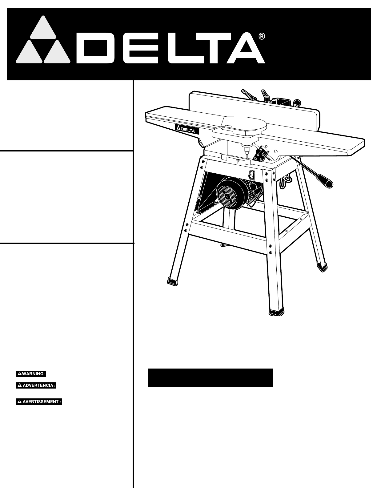
6" (152mm)
Jointer with Stand
Dégauchisseuse
de 152 mm (6 po)
JT360
avec support
Canteador de
152 mm (6 pulg)
con base
TO REDUCE THE RISK OF INJURY,
MANUAL BEFORE OPERATING PRODUCT.
DEBE LEER EL MANUAL DE INSTRUCCIONES ANTES
DE OPERAR EL PRODUCTO
L’UTILISATEUR DOIT LIRE LE MODE
AVANT D’UTILISER LE PRODUIT.
USER MUST READ INSTRUCTION
PARA REDUCIR EL RIESGO
DE LESIONES, EL USUARIO
AFIN DE RÉDUIRE LE
BLESSURES,
RISQUE DE
D’EMPLOI
Instruction Manual
Manuel d’utilisation
Manual de instrucciones
FRANÇAIS 27 ESPAÑOL 52
WWW.DELTAMACHINERY.COM
(800) 223-7278 - US
(800) 463-3582 - CANADA
A23771 - 06-13-07
Copyright © 2007 Delta Machinery
Page 2
TABLE OF CONTENTS
IMPORTANT SAFETY INSTRUCTIONS ....................2
SAFETY GUIDELINES - DEFINITIONS .....................2
GENERAL SAFETY RULES .......................................3
ADDITIONAL SPECIFIC SAFETY RULES ................4
FUNCTIONAL DESCRIPTION ...................................7
CARTON CONTENTS ...............................................7
ASSEMBLY ................................................................. 9
OPERATION ...............................................................15
TROUBLESHOOTING ................................................24
MAINTENANCE .......................................................... 25
SERVICE ............................................................... 25-26
ACCESSORIES .......................................................... 26
WARRANTY ............................................................... 26
FRANÇAIS ................................................................. 27
ESPAÑOL ................................................................... 52
IMPORTANT SAFETY INSTRUCTIONS
Read and understand all warnings and operating instructions before using any tool
or equipment. When using tools or equipment, basic safety precautions should always be followed
to reduce the risk of personal injury. Improper operation, maintenance or modification of tools or
equipment could result in serious injury and property damage. There are certain applications for which
tools and equipment are designed. Delta Machinery strongly recommends that this product NOT be modified and/or
used for any application other than for which it was designed.
If you have any questions relative to its application DO NOT use the product until you have written Delta Machinery and
we have advised you. Contact us online at www.deltamachinery.com or by mail at Technical Service Manager, Delta
Machinery, 4825 Highway 45 North, Jackson, TN 38305. In Canada,125 Mural St. Suite 300, Richmond Hill, ON, L4B 1M4)
Information regarding the safe and proper operation of this tool is available from the following sources:
• Power Tool Institute, 1300 Sumner Avenue, Cleveland, OH 44115-2851or online at www.powertoolinstitute.org
• National Safety Council, 1121 Spring Lake Drive, Itasca, IL 60143-3201
• American National Standards Institute, 25 West 43rd Street, 4 floor, New York, NY 10036 www.ansi.org - ANSI 01.1
Safety Requirements for Woodworking Machines
• U.S. Department of Labor regulations www.osha.gov
SAVE THESE INSTRUCTIONS!
SAFETY GUIDELINES - DEFINITIONS
It is important for you to read and understand this manual. The information it contains relates to protecting YOUR SAFETY
and PREVENTING PROBLEMS. The symbols below are used to help you recognize this information.
Indicates an imminently hazardous situation which, if not avoided, will result in death or serious
injury.
Indicates a potentially hazardous situation which, if not avoided, could result in death or serious
injury.
Indicates a potentially hazardous situation which, if not avoided, may result in minor or moderate
injury.
Used without the safety alert symbol indicates a potentially hazardous situation which, if not avoided,
may result in property damage.
CALIFORNIA PROPOSITION 65
Some dust created by power sanding, sawing, grinding, drilling, and other construction activities
contains chemicals known to cause cancer, birth defects or other reproductive harm. Some
examples of these chemicals are:
• lead from lead-based paints,
• crystalline silica from bricks and cement and other masonry products, and
• arsenic and chromium from chemically-treated lumber.
Your risk from these exposures varies, depending on how often you do this type of work. To reduce your
exposure to these chemicals: work in a well ventilated area, and work with approved safety equipment, al ways
wear NIOSH/OSHA approved, properly fit ting face mask or res pi ra tor when us ing such tools.
2 - English
Page 3

GENERAL SAFETY RULES
Failure to follow these rules may result in serious personal injury.
1. FOR YOUR OWN SAFETY, READ THE INSTRUCTION
MANUAL BEFORE OPERATING THE MACHINE. Learning
the machine’s application, limitations, and specific hazards
will greatly minimize the possibility of accidents and injury.
2. WEAR EYE AND HEARING PROTECTION. ALWAYS
USE SAFETY GLASSES. Everyday eyeglasses are NOT
safety glasses. USE CERTIFIED SAFETY EQUIPMENT.
Eye protection equipment should comply with ANSI Z87.1
standards. Hearing equipment should comply with ANSI
S3.19 standards.
3. WEAR PROPER APPAREL. Do not wear loose clothing,
gloves, neckties, rings, bracelets, or other jewelry which may
get caught in moving parts. Nonslip protective footwear is
recommended. Wear protective hair covering to contain long
hair.
4. DO NOT USE THE MACHINE IN A DANGEROUS
ENVIRONMENT. The use of power tools in damp or wet
locations or in rain can cause shock or electrocution. Keep
your work area well-lit to prevent tripping or placing arms,
hands, and fingers in danger.
5. MAINTAIN ALL TOOLS AND MACHINES IN PEAK
CONDITION. Keep tools sharp and clean for best and safest
performance. Follow instructions for lubricating and changing
accessories. Poorly maintained tools and machines can further
damage the tool or machine and/or cause injury.
6. CHECK FOR DAMAGED PARTS. Before using the machine,
check for any damaged parts. Check for alignment of moving
parts, binding of moving parts, breakage of parts, and any
other conditions that may affect its operation. A guard or any
other part that is damaged should be properly repaired or
replaced with Delta or factory authorized replacement
parts. Damaged parts can cause further damage to the
machine and/or injury.
7. KEEP THE WORK AREA CLEAN. Cluttered areas and benches
invite accidents.
8. KEEP CHILDREN AND VISITORS AWAY. Your shop is a
potentially dangerous environment. Children and visitors can be
injured.
9. REDUCE THE RISK OF UNINTENTIONAL STARTING. Make
sure that the switch is in the "OFF" position before plugging
in the power cord. In the event of a power failure, move the
switch to the "OFF" position. An accidental start-up can cause
injury. Do not touch the plug’s metal prongs when unplugging
or plugging in the cord.
10. USE THE GUARDS. Check to see that all guards are in place,
secured, and working correctly to prevent injury.
11. REMOVE ADJUSTING KEYS AND WRENCHES BEFORE
STARTING THE MACHINE. Tools, scrap pieces, and other
debris can be thrown at high speed, causing injury.
12. USE THE RIGHT MACHINE. Don’t force a machine or an
attachment to do a job for which it was not designed. Damage
to the machine and/or injury may result.
13. USE RECOMMENDED ACCESSORIES. The use of
accessories and attachments not recommended by Delta
may cause damage to the machine or injury to the user.
14. USE THE PROPER EXTENSION CORD. Make sure your
extension cord is in good condition. When using an extension
cord, be sure to use one heavy enough to carry the current
your product will draw. An undersized cord will cause a drop
in line voltage, resulting in loss of power and overheating. See
the Extension Cord Chart for the correct size depending on
the cord length and nameplate ampere rating. If in doubt, use
the next heavier gauge. The smaller the gauge number, the
heavier the cord.
15. SECURE THE WORKPIECE. Use clamps or a vise to hold the
workpiece when practical. Loss of control of a workpiece can
cause injury.
16. FEED THE WORKPIECE AGAINST THE DIRECTION OF
THE ROTATION OF THE BLADE, CUTTER, OR ABRASIVE
SURFACE. Feeding it from the other direction will cause the
workpiece to be thrown out at high speed.
17. DON’T FORCE THE WORKPIECE ON THE MACHINE.
Damage to the machine and/or injury may result.
18. DON’T OVERREACH. Loss of balance can make you fall into
a working machine, causing injury.
19. NEVER STAND ON THE MACHINE. Injury could occur if the tool
tips, or if you accidentally contact the cutting tool.
20. NEVER LEAVE THE MACHINE RUNNING UNATTENDED.
TURN THE POWER OFF. Don’t leave the machine until it comes
to a complete stop. A child or visitor could be injured.
21. TURN THE MACHINE "OFF", AND DISCONNECT THE
MACHINE FROM THE POWER SOURCE before installing or
removing accessories, changing cutters, adjusting or changing
set-ups. When making repairs, be sure to lock the start switch
in the "OFF" position. An accidental start-up can cause injury.
22. MAKE YOUR WORKSHOP CHILDPROOF WITH
PADLOCKS, MASTER SWITCHES, OR BY REMOVING
STARTER KEYS. The accidental start-up of a machine by a
child or visitor could cause injury.
23
. STAY ALERT, WATCH WHAT YOU ARE DOING, AND USE
COMMON SENSE. DO NOT USE THE MACHINE WHEN
YOU ARE TIRED OR UNDER THE INFLUENCE OF DRUGS,
ALCOHOL, OR MEDICATION. A moment of inattention while
operating power tools may result in injury.
24.
USE OF THIS TOOL CAN GENERATE AND
DISBURSE DUST OR OTHER AIRBORNE PARTICLES,
INCLUDING WOOD DUST, CRYSTALLINE SILICA DUST
AND ASBESTOS DUST. Direct particles away from face
and body. Always operate tool in well ventilated area and
provide for proper dust removal. Use dust collection system
wherever possible. Exposure to the dust may cause serious
and permanent respiratory or other injury, including silicosis (a
serious lung disease), cancer, and death. Avoid breathing the
dust, and avoid prolonged contact with dust. Allowing dust to
get into your mouth or eyes, or lay on your skin may promote
absorption of harmful material. Always use properly fitting
NIOSH/OSHA approved respiratory protection appropriate for
the dust exposure, and wash exposed areas with soap and
water.
3 - English
Page 4

ADDITIONAL SPECIFIC SAFETY RULES
Failure to follow these rules may result in serious personal injury.
1. DO NOT OPERATE THIS MACHINE
until it is completely assembled and installed
according to the instructions. A machine incorrectly
assembled can cause serious injury.
2. OBTAIN ADVICE from your supervisor,
instructor, or another qualified person if you are
not thoroughly familiar with the operation of this
machine. Knowledge is safety.
3. FOLLOW ALL WIRING CODES and
recommended electrical connections to prevent
shock or electrocution.
4. KEEP KNIVES SHARP and free from rust and
pitch. Dull or rusted knives work harder and can
cause kickback.
5. TIGHTEN THE INFEED/OUTFEED TABLES before
starting the machine. Loss of control of the workpiece can cause serious injury.
6. PROPERLY SECURE THE BLADES IN THE
CUTTERHEAD before turning the power "ON".
Loose blades may be thrown out at high speeds.
7. NEVER TURN THE MACHINE "ON" before clearing
the table of all objects (tools, scraps of wood, etc.).
Flying debris can cause serious injury.
8. NEVER TURN THE MACHINE "ON" with the
workpiece contacting the cutterhead. Kickback
can occur.
9. AVOID AWKWARD OPERATIONS AND HAND
POSITIONS. A sudden slip could cause a hand to
move into the cutterhead.
10. KEEP ARMS, HANDS, AND FINGERS away from
the cutterhead to prevent severe injury.
11. NEVER MAKE CUTS deeper than 1/8" (3.2mm) to
prevent kickback.
12. NEVER JOINT OR PLANE A WORKPIECE
that is shorter than 10" (254mm), narrower than
3/4" (19.0MM), or less than 1/2" (12.7mm) thick.
Jointing smaller workpieces can place your hand
in the cutterhead causing severe injury.
13. USE HOLD-DOWN/PUSH BLOCKS for jointing
or planing any workpiece lower than the fence.
Jointing or planing small workpieces can result in
kickback and severe injury.
14. HOLD THE WORKPIECE FIRMLY against the
table and fence. Loss of control of the workpiece
can cause kickback and result in serious injury.
15. NEVER PERFORM "FREE-HAND" OPERATIONS.
Use the fence to position and guide the workpiece.
Loss of control of the workpiece can cause serious
injury.
16. DO NOT attempt to perform an abnormal or
little-used operation without study and the use of
adequate hold-down/push blocks, jigs, fixtures,
stops, etc.
17. DO NOT FEED A WORKPIECE into the outfeed
end of the machine.The workpiece will be thrown
out of the opposite end at high speeds.
18. DO NOT FEED A WORKPIECE that is warped,
contains knots, or is embedded with foreign
objects (nails, staples, etc.) to prevent kickback.
19. MAINTAIN THE PROPER RELATIONSHIP OF
INFEED AND OUTFEED TABLE SURFACES and
cutterhead knife path. Loss of control of the workpiece can cause serious injury.
20. PROPERLY SUPPORT LONG OR WIDE
WORKPIECES. Loss of control of the workpiece can
cause injury.
21. NEVER PERFORM LAYOUT, ASSEMBLY, OR SET-
UP WORK on the table/work area when the
machine is running. A sudden slip could cause a
hand to move into the cutterhead. Severe injury
can result.
22. TURN THE MACHINE "OFF", disconnect the
machine from the power source, and clean the
table/work area before leaving the machine. LOCK
THE SWITCH IN THE "OFF" POSITION to prevent
unauthorized use. Someone else might accidentally
start the machine and cause injury to themselves.
23. ADDITIONAL INFORMATION regarding the safe and
proper operation of power tools (i.e. a safety video)
is available from the Power Tool Institute, 1300
Sumner Avenue, Cleveland, OH 44115-2851 (www.
powertoolinstitute.com). Information is also available
from the National Safety Council, 1121 Spring Lake
Drive, Itasca, IL 60143-3201. Please refer to the
American National Standards Institute ANSI 01.1
Safety Requirements for Woodworking Machines
and the U.S. Department of Labor OSHA 1910.213
Regulations.
SAVE THESE INSTRUCTIONS.
Refer to them often and use them to instruct others.
4 - English
Page 5
POWER CONNECTIONS
A separate electrical circuit should be used for your machines. This circuit should not be less than #12 wire and should
be protected with a 20 Amp time lag fuse. If an extension cord is used, use only 3-wire extension cords which have
3-prong grounding type plugs and matching receptacle which will accept the machine’s plug. Before connecting the
machine to the power line, make sure the switch (s) is in the "OFF" position and be sure that the electric current is of
the same characteristics as indicated on the machine. All line connections should make good contact. Running on low
voltage will damage the machine.
Do not expose the machine to rain or operate the machine in damp locations.
MOTOR SPECIFICATIONS
Your machine is wired for 120/240 volts, 60 HZ alternating current. Before connecting the machine to the power source,
make sure the switch is in the "OFF" position.
GROUNDING INSTRUCTIONS
This machine must be grounded while in use to protect the operator from electric shock.
1. All grounded, cord-connected machines:
In the event of a malfunction or breakdown, grounding provides a path of least resistance for electric current to
reduce the risk of electric shock. This machine is equipped with an electric cord having an equipment-grounding
conductor and a grounding plug. The plug must be plugged into a matching outlet that is properly installed and
grounded in accordance with all local codes and ordinances.
Do not modify the plug provided - if it will not fit the outlet, have the proper outlet installed by a qualified electrician.
Improper connection of the equipment-grounding conductor can result in risk of electric shock. The conductor
with insulation having an outer surface that is green with or without yellow stripes is the equipment-grounding
conductor. If repair or replacement of the electric cord or plug is necessary, do not connect the equipment-
grounding conductor to a live terminal.
Check with a qualified electrician or service personnel if the grounding instructions are not completely
understood, or if in doubt as to whether the machine is properly grounded.
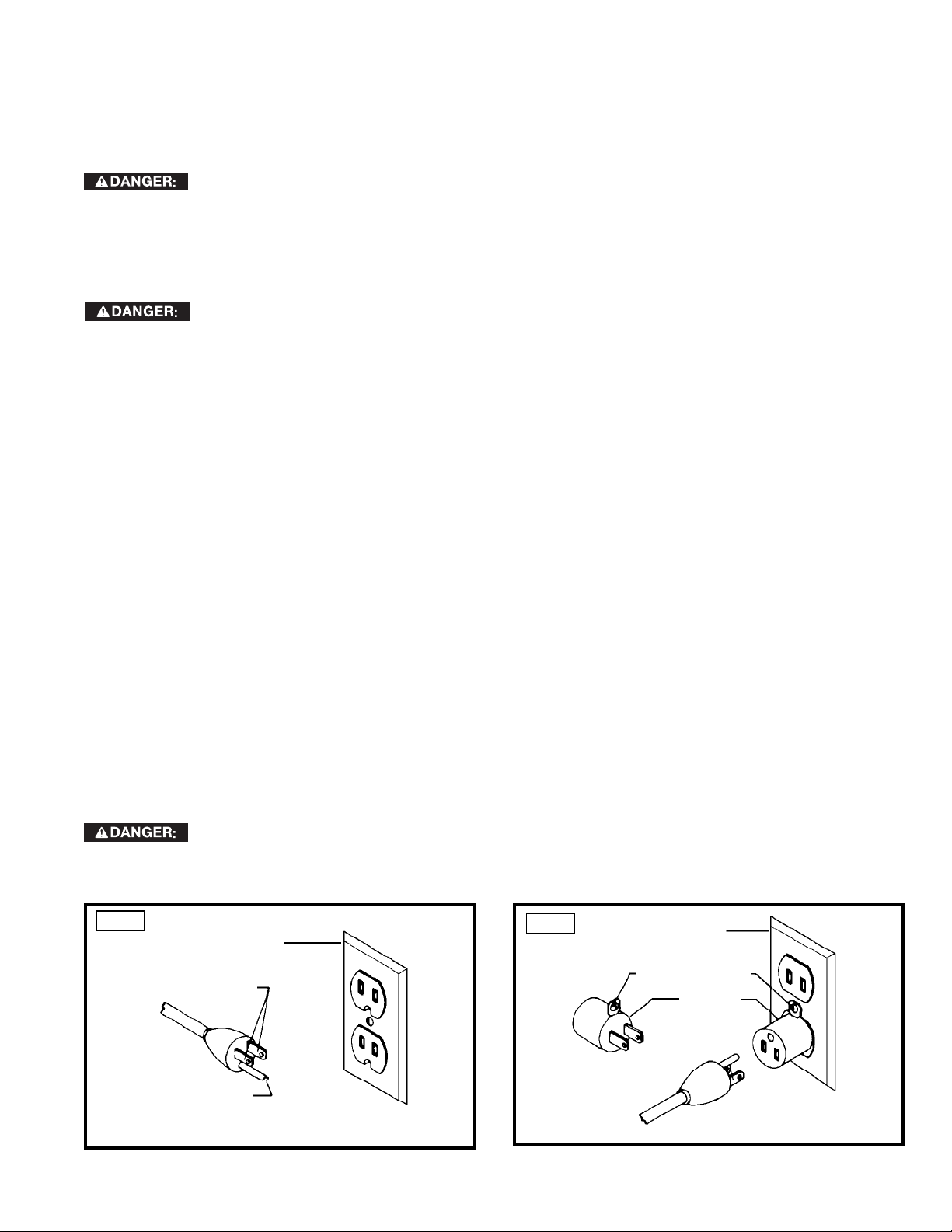
Use only 3-wire extension cords that have 3-prong grounding type plugs and matching 3-conductor receptacles that
accept the machine’s plug, as shown in Fig. A.
Repair or replace damaged or worn cord immediately.
2. Grounded, cord-connected machines intended for use on a supply circuit having a nominal rating less
than 150 volts:
If the machine is intended for use on a circuit that has an outlet that looks like the one illustrated in Fig. A, the
machine will have a grounding plug that looks like the plug illustrated in Fig. A. A temporary adapter, which looks
like the adapter illustrated in Fig. B, may be used to connect this plug to a matching 2-conductor receptacle as
shown in Fig. B if a properly grounded outlet is not available. The temporary adapter should be used only until
a properly grounded outlet can be installed by a qualified electrician. The green-colored rigid ear, lug, and the
like, extending from the adapter must be connected to a permanent ground such as a properly grounded outlet
box. Whenever the adapter is used, it must be held in place with a metal screw.
NOTE: In Canada, the use of a temporary adapter is not permitted by the Canadian Electric Code.
In all cases, make certain that the receptacle in question is properly grounded. If you are not sure,
have a qualified electrician check the receptacle.
Fig. A
GROUNDED OUTLET BOX
GROUNDING BLADE
IS LONGEST OF THE 3 BLADES
CURRENT
CARRYING
PRONGS
5 - English
Fig. B
GROUNDED OUTLET BOX
GROUNDING MEANS
ADAPTER
Page 6
3. 240 VOLT SINGLE PHASE OPERATION
The motor supplied with your machine is a dual
voltage, 120/240 volt motor. It is shipped readyto-run for 120 volt operation. However, it can be
converted for 240 volt operation.
A qualified electrician should do the conversion, or
the machine can be taken to an Authorized Delta
Service Center. When completed, the machine must
conform to the National Electric Code and all local
codes and ordinances.
The machine is converted by re-wiring the motor
for 240 volts, installing a 240 volt plug on the power
supply cord and replacing the switch with one that is
rated for 240 volt operation. (Delta P/N 438-01-017-
0141 needed for 240 volt operation.)
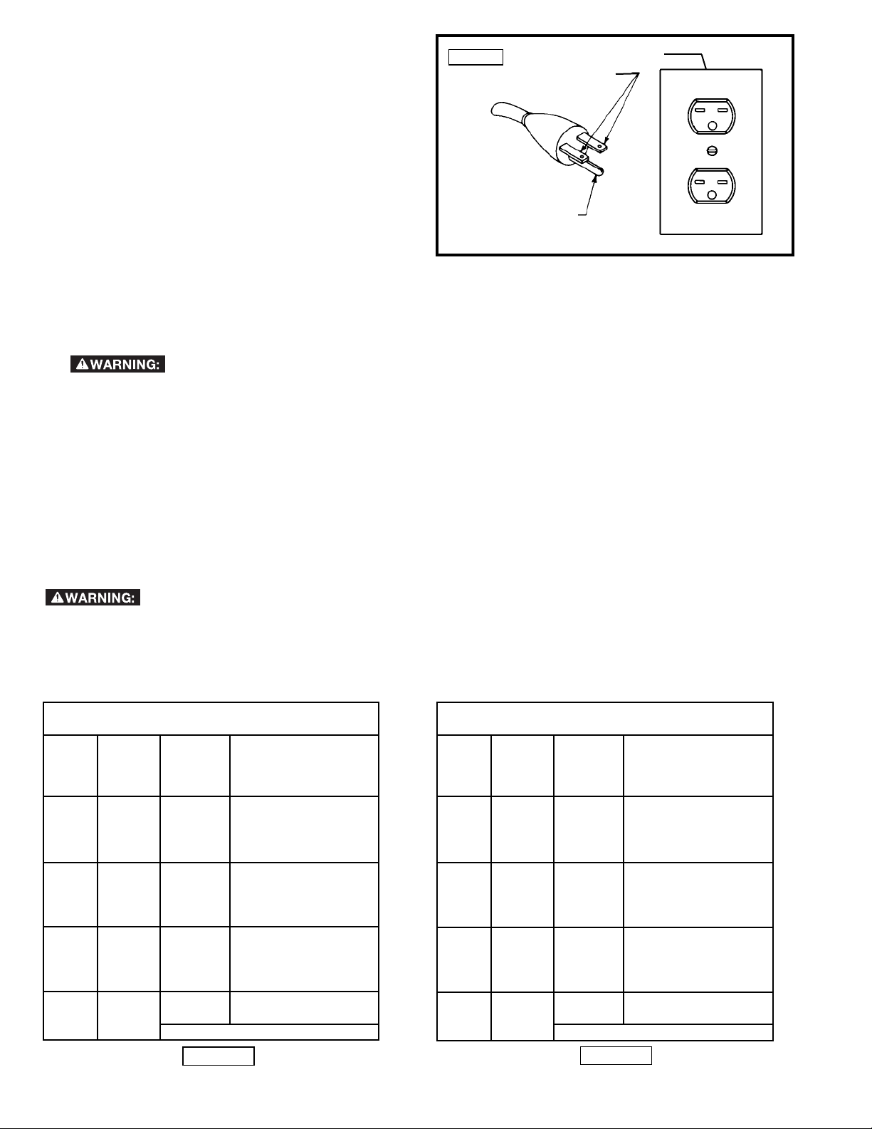
Be sure the 240 volt plug is only used in an outlet
having the same configuration as the plug illustrated
in Fig. C. No adapter should be used with the 240
volt plug.
In all cases, make certain that
the receptacle in question is properly grounded.
If you are not sure, have a qualified electrician
check the receptacle.
Fig. C
GROUNDING BLADE
IS LONGEST OF THE 3 BLADES
GROUNDED OUTLET BOX
CURRENT
CARRYING
PRONGS
EXTENSION CORDS
Use proper extension cords. Make sure your extension cord is in good condition and is a 3wire extension cord which has a 3-prong grounding type plug and matching receptacle which will accept the
machine’s plug. When using an extension cord, be sure to use one heavy enough to carry the current of the
machine. An undersized cord will cause a drop in line voltage, resulting in loss of power and overheating. Fig. D1 or D-2, shows the correct gauge to use depending on the cord length. If in doubt, use the next heavier gauge.
The smaller the gauge number, the heavier the cord.
MINIMUM GAUGE EXTENSION CORD
RECOMMENDED SIZES FOR USE WITH STATIONARY ELECTRIC MACHINES
Total
Ampere
Rating Volts
0-6 120
0-6 120 25-50 16 AWG
0-6 120 50-100 16 AWG
0-6 120 100-150 14 AWG
6-10 120
6-10 120 25-50 16 AWG
6-10 120 50-100 14 AWG
6-10 120 100-150 12 AWG
10-12 120
10-12 120 25-50 16 AWG
10-12 120 50-100 14 AWG
10-12 120 100-150 12 AWG
12-16 120
12-16 120 25-50 12 AWG
12-16 120
Length of
Cord in
Feet
up to
25 18 AWG
up to
25 18 AWG
up to
25 16 AWG
up to
GREATER THAN 50 FEET NOT RECOMMENDED
Fig. D-1
Gauge of Extension
Cord
25 14 AWG
MINIMUM GAUGE EXTENSION CORD
RECOMMENDED SIZES FOR USE WITH STATIONARY ELECTRIC MACHINES
Total
Ampere
Rating Volts
0-6 240
0-6 240 50-100 16 AWG
0-6 240 100-200 16 AWG
0-6 240 200-300 14 AWG
6-10 240
6-10 240 50-100 16 AWG
6-10 240 100-200 14 AWG
6-10 240 200-300 12 AWG
10-12 240
10-12 240 50-100 16 AWG
10-12 240 100-200 14 AWG
10-12 240 200-300 12 AWG
12-16 240
12-16 240 50-100 12 AWG
12-16 240
Length of
Cord in
Feet
up to
50 18 AWG
up to
50 18 AWG
up to
50 16 AWG
up to 50
GREATER THAN 50 FEET NOT RECOMMENDED
Fig. D-2
Gauge of Extension
Cord
14 AWG
6 - English
Page 7
FUNCTIONAL DESCRIPTION
FOREWORD
The Delta JT360 6" (152mm) Jointer with Stand is designed with a cutting capacity of 6" (152mm) width, 1/2" (13mm)
depth and rabbeting 1/2" (13mm). Unit includes; heavy-duty 3/4 hp, 115/230 volt induction motor, stand, dust chute,
center-mounted fence, three-knife cutterhead, cutterhead guard, and push blocks
NOTICE: The manual cover illustrates the current production model. all other illustrations are representative only and
may not depict the actual color, labeling or accessories and may be intended to illustrate technique only.
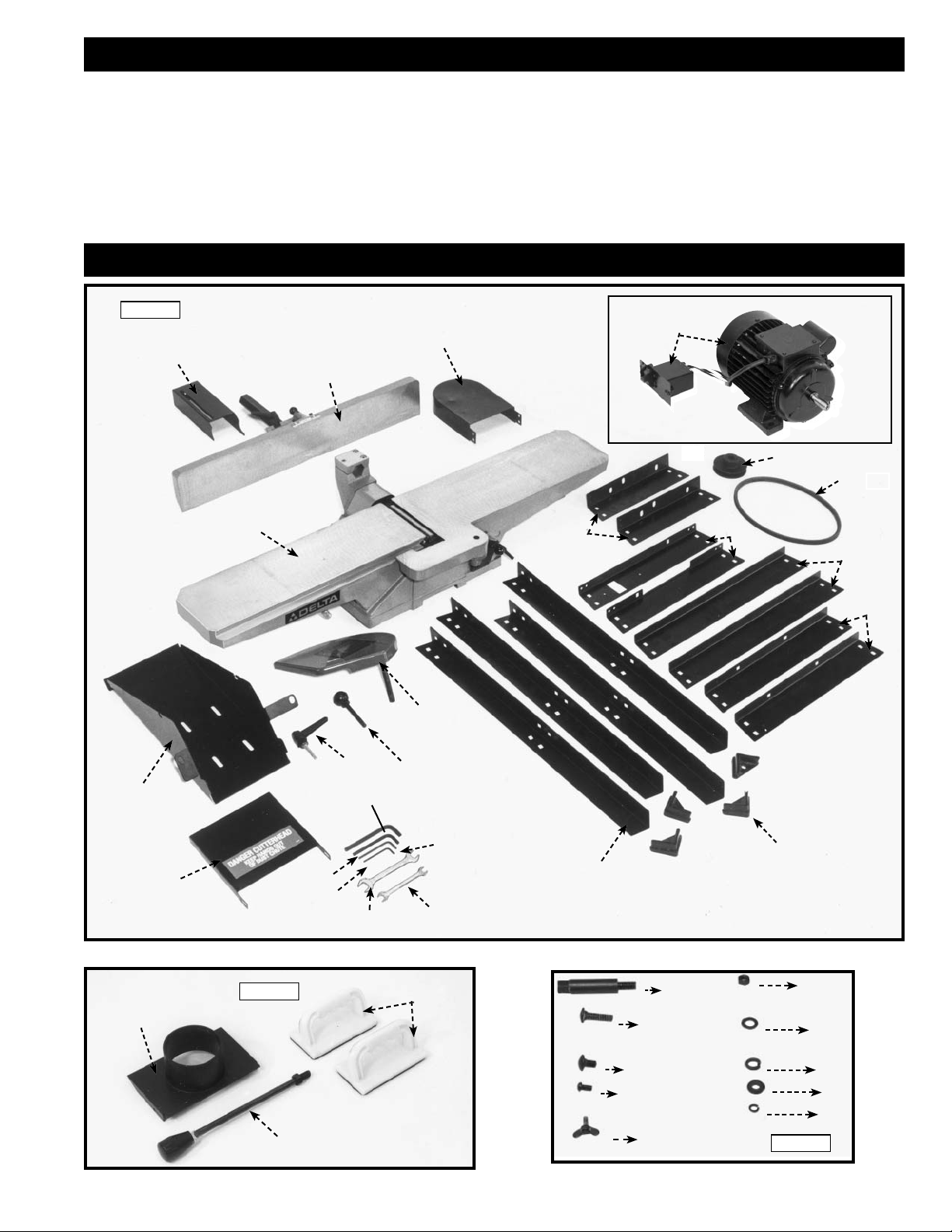
CARTON CONTENTS
Fig. 4
1
22
23
24
3
4
14
15
2
11
12
17
19
16
20
13
18
21
5
9
6
7
8
10
25
Fig. 4A
27
26
7 - English
31
30
29
32
28
33
34
35
36
37
Fig. 4B
Page 8

JOINTER PARTS
Fig. 4
1. Motor and Switch
2. Jointer
3. Motor Pulley
4. V-Belt
5. Two Top End Braces for Stand (11-3/4")
6. Two Top Side Braces for Stand (15-3/4")
7. Two Lower Side Braces for Stand (20-1/2")
8. Two Lower End Braces for Stand (16-1/2")
9. Four Legs for Stand
10. Four Feet for Stand Legs
11. Cutterhead Guard
12. Fence Locking Handle
13. Fence Tilting Handle
14. Dust Chute
15. Dust Chute Cover
16. 6mm Allen Wrench
17. 4mm Allen Wrench
18. 3mm Allen Wrench
Fig. 4A
25. Dust Collector Adapter
26. Push Blocks
27. Infeed Table Adjustment Rod, Handle, and Nut
Fig. 4B
28. Special Studs (3)
29. 5/16-18x1¼" Carriage Bolts (4)
30. 5/16-18x3/4" Carriage Bolts (36)
31. M6x1x10mm Cheese Head Screws (4)
32. Wing Screws (2)
33. 5/16-18Hex Nuts (40)
34. 5/16 Flat Washers (36)
35. M10.2 Lockwashers for Special Studs (3)
36. M8.4 Flat Washer
37. M6.1 Lockwashers (4)
19. 2.5mm Allen Wrench
20. 12x14mm Open End Wrench
21. 8x10mm Open End Wrench
22. Rear Cutterhead Guard
23. Fence
24. Motor Pulley and Belt Guard
UNPACKING AND CLEANING
Carefully unpack the machine and all loose items from the shipping container(s). Remove the rust-preventative oil from
unpainted surfaces using a soft cloth moistened with mineral spirits, paint thinner or denatured alcohol.
Jointer weight is approximately 175 lbs. Care must be taken when lifting jointer onto stand. A
minimum of two people will be required to lift the machine.
Do not use highly volatile solvents such as gasoline, naphtha, acetone or lacquer thinner for cleaning your
machine.
After cleaning, cover the unpainted surfaces with a good quality household floor paste wax.
8 - English
Page 9
ASSEMBLY
For your own safety, do not connect the machine to the power source until the machine is
completely assembled and you read and understand the entire instruction manual.
ASSEMBLY TOOLS REQUIRED
* 6mm Allen Wrench
* 4mm Allen Wrench
* 3mm Allen Wrench
* 2.5mm Allen Wrench
ASSEMBLY TIME ESTIMATE - 2-3 hours
* 12x14mm Open End Wrench
* 8x10mm Open End Wrench
(All are supplied.)
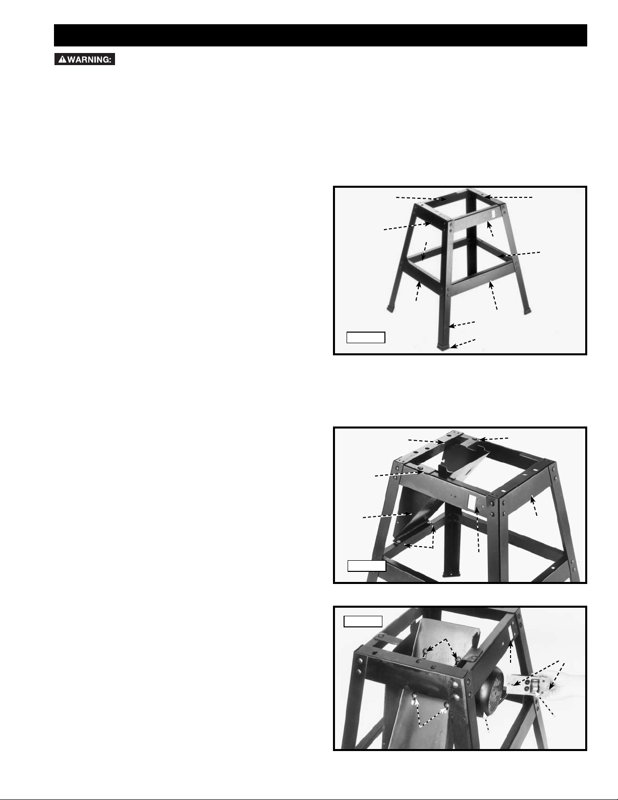
STAND
1. Assemble stand as shown in Fig. 5 using parts shown
in Fig. 4. The parts for the stand (as shown in Fig. 4)
are:
5. Two Top End Braces for Stand (11-3/4")
6. Two Top Side Braces for Stand (15-3/4")
7. Two Lower Side Braces for Stand (20-1/2")
8. Two Lower End Braces for Stand (16-1/2")
9. Four Legs for Stand
10. Four Feet for Stand Legs
To assemble, insert the 5/16-18x3/4" carriage head
bolts through legs and braces then place the 5/16"
flat washers on the bolts and secure with the 5/16-18
hex nuts. Only tighten nuts finger-tight at this time.
IMPORTANT: The top lips of two upper end braces
(5) Fig. 5, must fit on top of the top lips of two upper
side braces (6).
2. Assemble four rubber feet (10), to the bottom of each
leg (9) as shown.
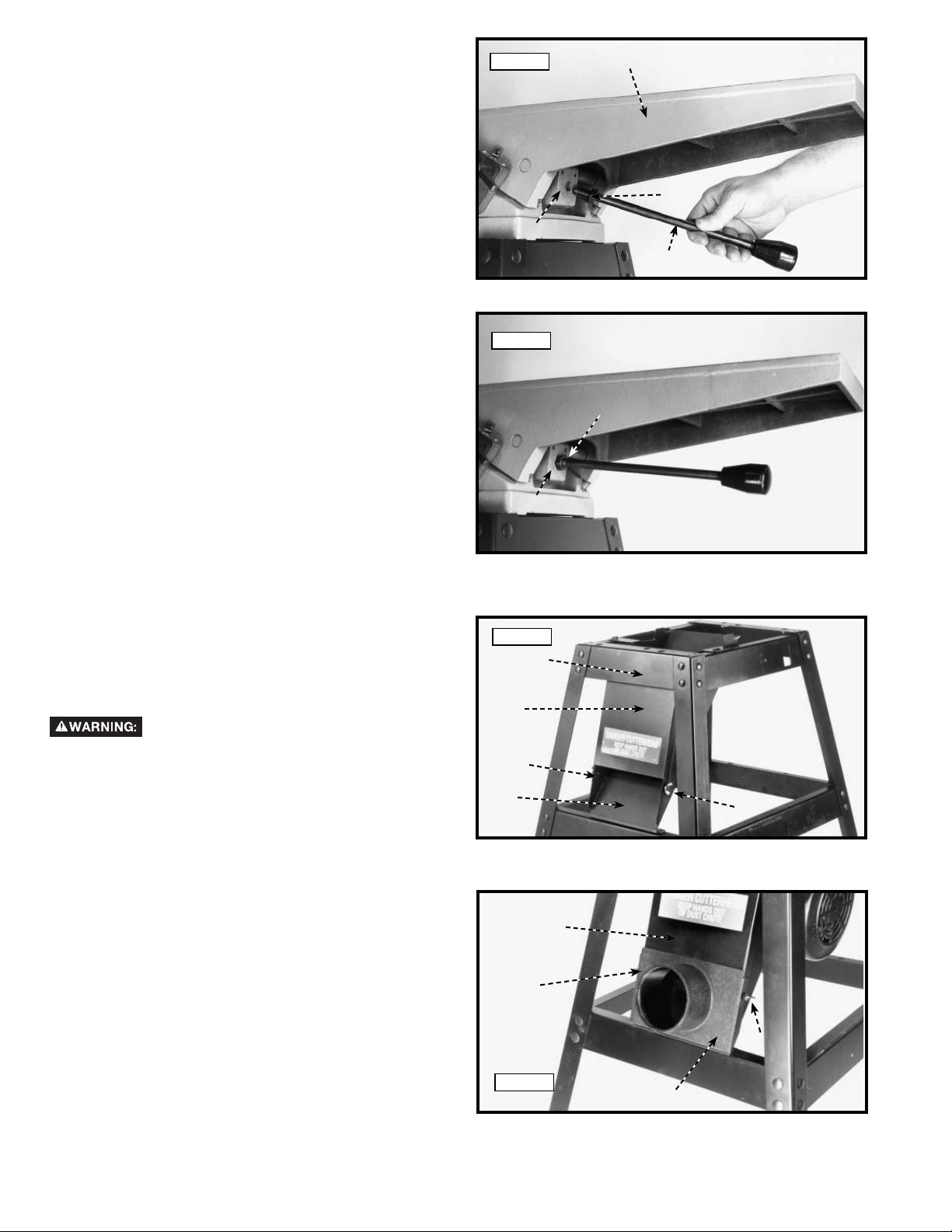
DUST CHUTE TO STAND
1. The front of the stand is indicated by switch opening
(B) Fig. 6, making the outfeed end of the stand (C)
and the infeed end (A).
2. Assemble dust chute (E) Fig. 6, to outfeed end of
stand (C) as shown. Align the four holes (D) Fig. 6, in
the dust chute with the four holes in the stand. Insert
a 5/16-18x3/4" carriage bolt through the hole in the
dust chute and stand. Place a 5/16" flat washer onto
the screw and thread a 5/16-18 hex nut onto the
screw. Repeat this process for the three remaining
holes in the dust chute and stand. Only tighten hex
nuts fingertight at this time.
Fig. 5
D
E
Fig. 6
6
5
7
8
C
D
9
10
B
6
7
5
8
D
A
MOTOR AND SWITCH TO STAND
1. Assemble motor (B) Fig. 7, to the bottom of the
dust chute. Align the four holes (F) Fig. 7, in the dust
chute, with the four holes in the motor mounting
plate. Insert a 5/16-18x1¼"carriage bolt through
hole in dust chute and hole in motor mounting plate.
Place a 5/16" flat washer on screw and secure with
a 5/16-18 hex nut. Repeat this process for the three
remaining holes. Do not com plete ly tighten hex
nuts at this time as the motor must be adjusted
for proper alignment and belt tension later.
9 - English
Fig. 7
F
D
F
B
A
C
Page 10
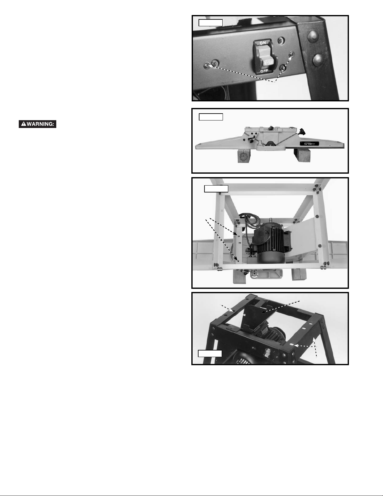
2. Remove M4x.7x10mm pan head screws, M4.1 flat
washers and M4x.7 hex nuts from two holes (A) Fig.
7 in switch.
3. Insert switch assembly (C) Fig. 7 from the inside of
the stand. Align the holes (A) in the switch with the
holes in the stand (A) Fig. 8.
4. Place a M4.1 flat washer onto a M4x.7x10mm pan
head screw. Insert screw through hole (A) in stand
and switch. Thread a M4x.7 hex nut onto screw.
Repeat this process for the remaining hole in stand
and switch.
Fig. 8
A
JOINTER TO STAND
Jointer weight is approximately 175 lbs.
Care must be taken when moving it. A
minimum of two people will be required to lift the machine.
1. Turn jointer upside down so it lays flat. One way to
do this is to place the jointer table onto two wooden
4x4s as shown in Fig. 9A.
2. Turn the stand upside down and align the threaded
holes in the bottom of the jointer with the holes in
the stand, two of which are shown at (A) Fig. 9B.
The infeed end of the jointer is fastened to the stand
through these two holes (A) Fig. 9B and (A) fig. 9C.
The outfeed end of the jointer is fastened to the stand
through hole (B) Fig. 9C.
Fig. 9A
Fig. 9B
A
10 - English
B
Fig. 9C
C
A
Page 11
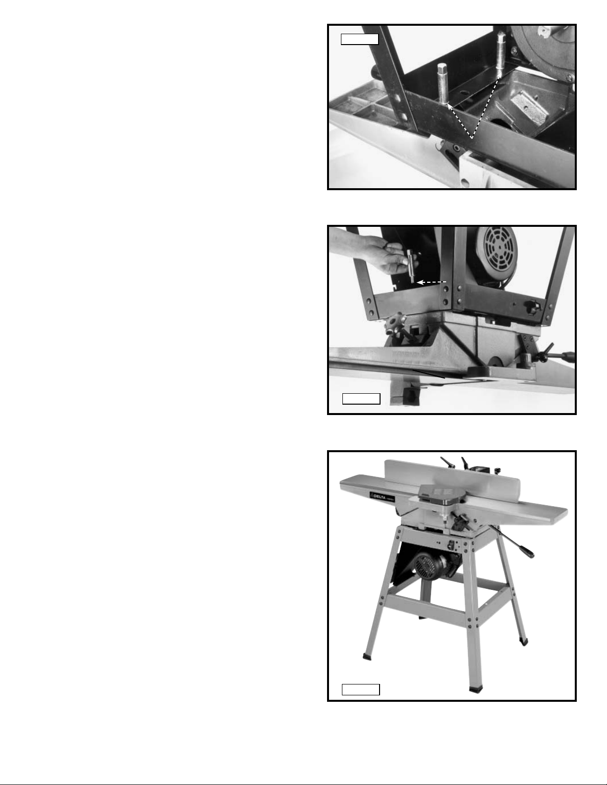
3. Using the supplied wrench (or a 14 mm socket
wrench), fasten the jointer to the top of stand using
the three M10.2 lockwashers and three special
studs. Two of the special studs are shown at (D) Fig.
10. These are for the infeed end of the machine. The
other special stud is shown at (D) Fig. 11, for the
outfeed end of machine. Fully tighten the studs at
this time.
4. Once the jointer is completely secured to stand,
stand the machine upright. (Jointer is shown upright
and fully assembled in Fig. 11A.)
5. Push downward on the top of jointer until the stand
adjusts to the floor surface. Then using the supplied
wrench, tighten all stand hardware.
Fig. 10
D
D
Fig. 11
11 - English
Fig.11A
Page 12
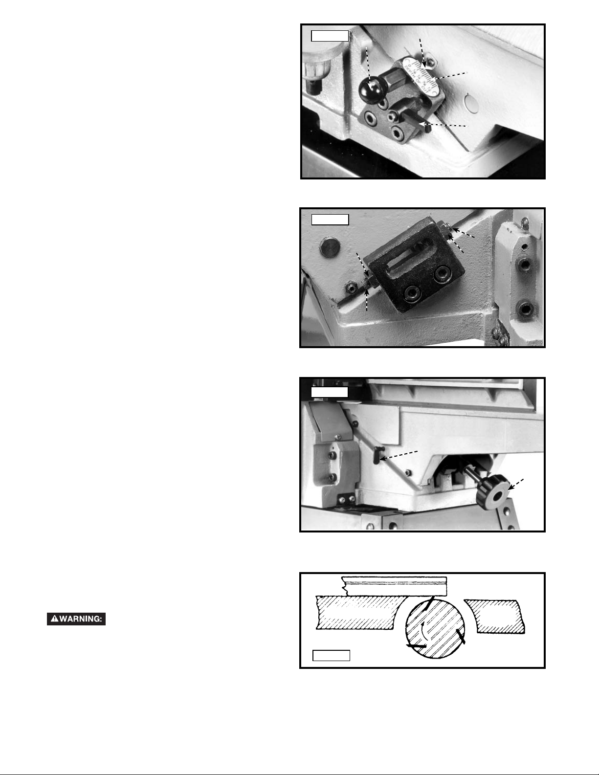
INFEED TABLE ADJUSTMENT HANDLE
1. Turn lock nut (C) Fig. 12, clock wise on infeed table
ad just ment handle (B) as far as it will go.
2. Thread handle (B) Fig. 12, into block (D) which is
located below infeed table (E).
3. Turn locknut (C) Fig. 13 clockwise to tighten against
block (D).
Fig. 12
D
Fig. 13
D
E
C
B
C
DUST CHUTE COVER
1. Assemble dust chute cover (A) Fig. 14, to dust chute
(B) using two wing screws (C). IMPORTANT: Top of
dust chute cover (A) must be inside top brace (D) of
stand.
During operation, the dust chute cover
(A) must always be assembled as shown and should
only be removed for cleaning.
DUST COLLECTOR ADAPTER
If the machine is to be connected to a dust collection
system, a dust collector adapter with a 4" O.D. opening
is supplied with the jointer. To assemble the adapter:
1. Remove two wing screws (C) Fig. 14, from dust chute
cover (A).
2. Assemble adapter (E) Fig. 15, over dust chute (A).
Align two holes in dust chute (A) with holes in adapter
(E) and fasten with two wing screws (C) which were
removed in STEP 1.
Fig. 14
A
C
B
C
Fig. 15
D
C
A
C
E
12 - English
Page 13
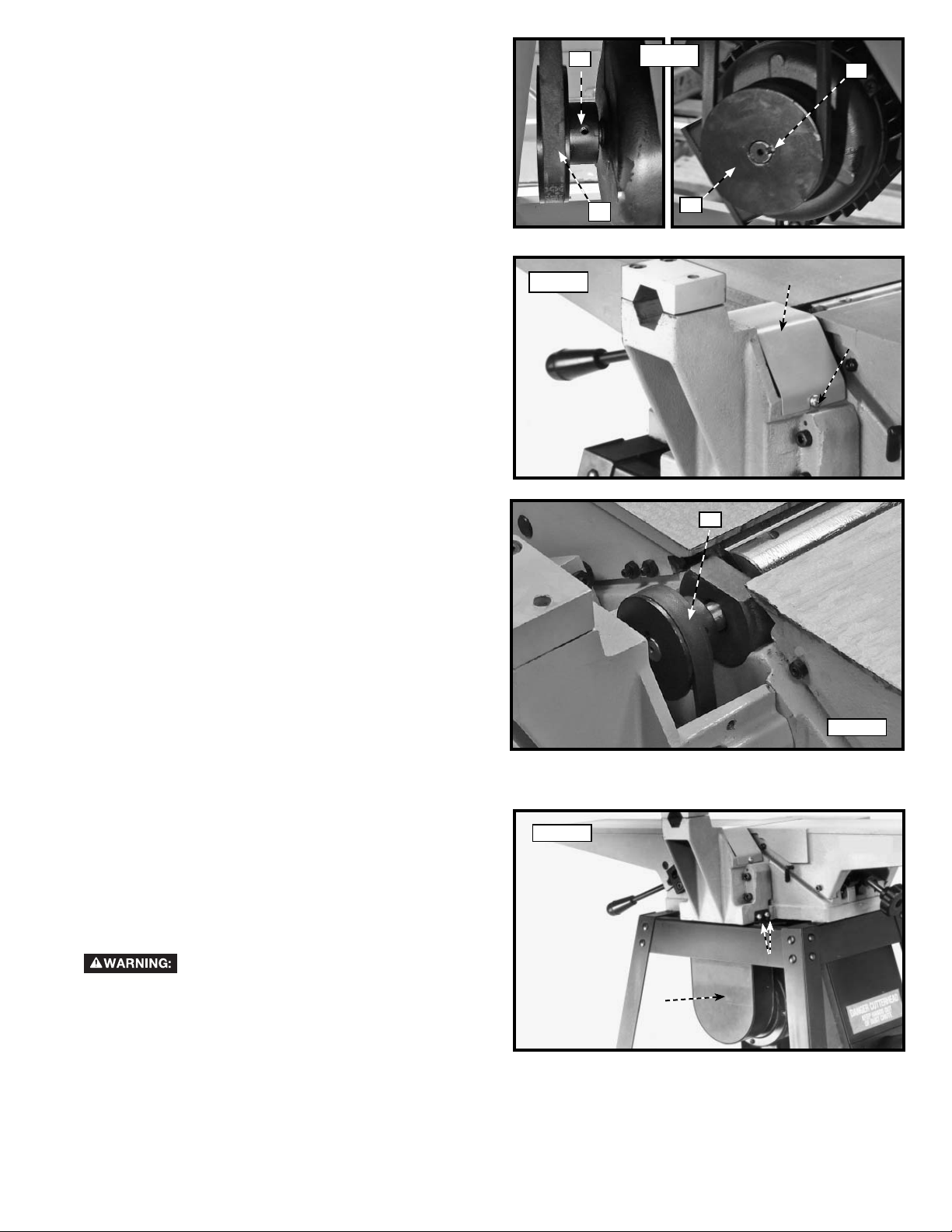
MOTOR PULLEY
Assemble motor pulley (A) Fig. 16, to motor shaft, as
shown. Make sure key (B) is inserted in the keyway of
the motor pulley and shaft.
C
Fig. 16
B
BELT, ALIGNING PULLEYS, AND
ADJUSTING BELT TENSION
1. Loosen two screws, one of which is shown at (A)
Fig. 17, and remove cutterhead pulley guard (B)
2. Make certain the motor pulley (D) Fig. 16, is aligned
with the cutterhead pulley (C) Fig. 18. If necessary,
the motor pulley (D) can be moved in or out on
the motor shaft to provide proper alignment. Then
tighten two set screws, one shown at (C) Fig. 16.
3. Place the belt in groove of cutterhead pulley (C) Fig.
18, and motor pulley (D) Fig. 16. To place belt onto
pulleys, lift up on motor. (Motor mounting hardware
should still be loose.)
4. Correct belt tension is obtained when there is ap proxi mate ly 1" deflection at the centerspan of the belt
using light finger pressure.
5. If an adjustment is required for belt tension, the
motor can be raised or lowered to obtain the correct
belt tension. Then tighten motor mounting hardware
after ten sion is applied, making sure alignment of the
pulleys is not dis turbed.
6. Replace cutterhead pulley guard (B) Fig. 17, which
was removed in STEP 1.
Fig. 17
D
A
B
A
C
MOTOR PULLEY AND BELT GUARD
Assemble the motor pulley and belt guard (A) Fig. 19, to
the jointer base using the four M6x1x10mm cheese head
screws, two of which are shown at (B), and four M6.1
lockwashers.
Make certain motor pulley is not
contacting guard. If motor pulley is contacting the guard,
adjust the motor pulley, see the section "BELT, ALIGNING
PULLEYS, AND ADJUSTING BELT TENSION."
Fig. 18
Fig. 19
B
A
13 - English
Page 14
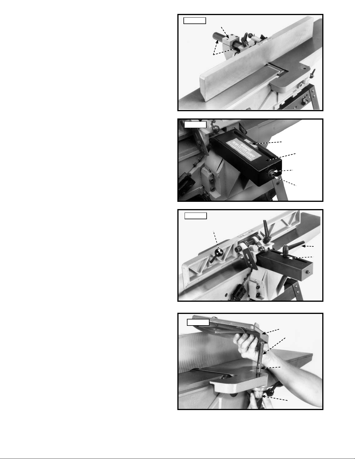
FENCE
1. Insert hexagon rod (A) Fig. 20, of fence assembly into
bracket (B) on jointer as shown.
Fig. 20
B
A
2. Remove the M8x1.25x12mm long screw (D) and
M8.4 flat washer (E) from the end of hexagon rod.
Assemble rear cutterhead guard (C) Fig. 21, to end of
hexagon rod using the M8x1.25x12mm long screw
(D) and M8.4 flat washer (E).
3. Thread fence locking handle assembly (F) Fig. 22, and
M8.4 flat washer (G) into hole (Z) Fig. 21. Lock handle
(F) Fig. 22, is spring-loaded and can be repositioned
by pulling out the handle and repositioning it onto the
serrated nut located under the handle.
4. Thread fence tilting handle (H) Fig. 22, to threaded
hole in back of fence as shown.
Fig. 21
Z
C
E
D
Fig. 22
H
F
G
CUTTERHEAD GUARD
1. Remove set screw (A) Fig. 23, from post (B) of
cutterhead guard (C).
2. Assemble cutterhead guard (C) Fig. 23, to the jointer
by inserting post (B) down through the hole in the
infeed table. NOTE: A spring is supplied in knob
assembly (D) that returns the guard (C) over the
cutterhead after a cut has been made. Turn knob
(D) to tension spring before inserting post (B). Make
certain the spring engages in the slot of the post.
To adjust spring tension, remove the cutterhead
guard (C) Fig. 23, and rotate knob (D) to the desired
amount of tension. NOTE: THE CUTTERHEAD
GUARD MUST BE TENSIONED SO THAT IT WILL
RETURN TO COVER THE CUTTERHEAD ONCE
THE MATERIAL HAS PASSED.
14 - English
Fig. 23
C
B
A
D
Page 15
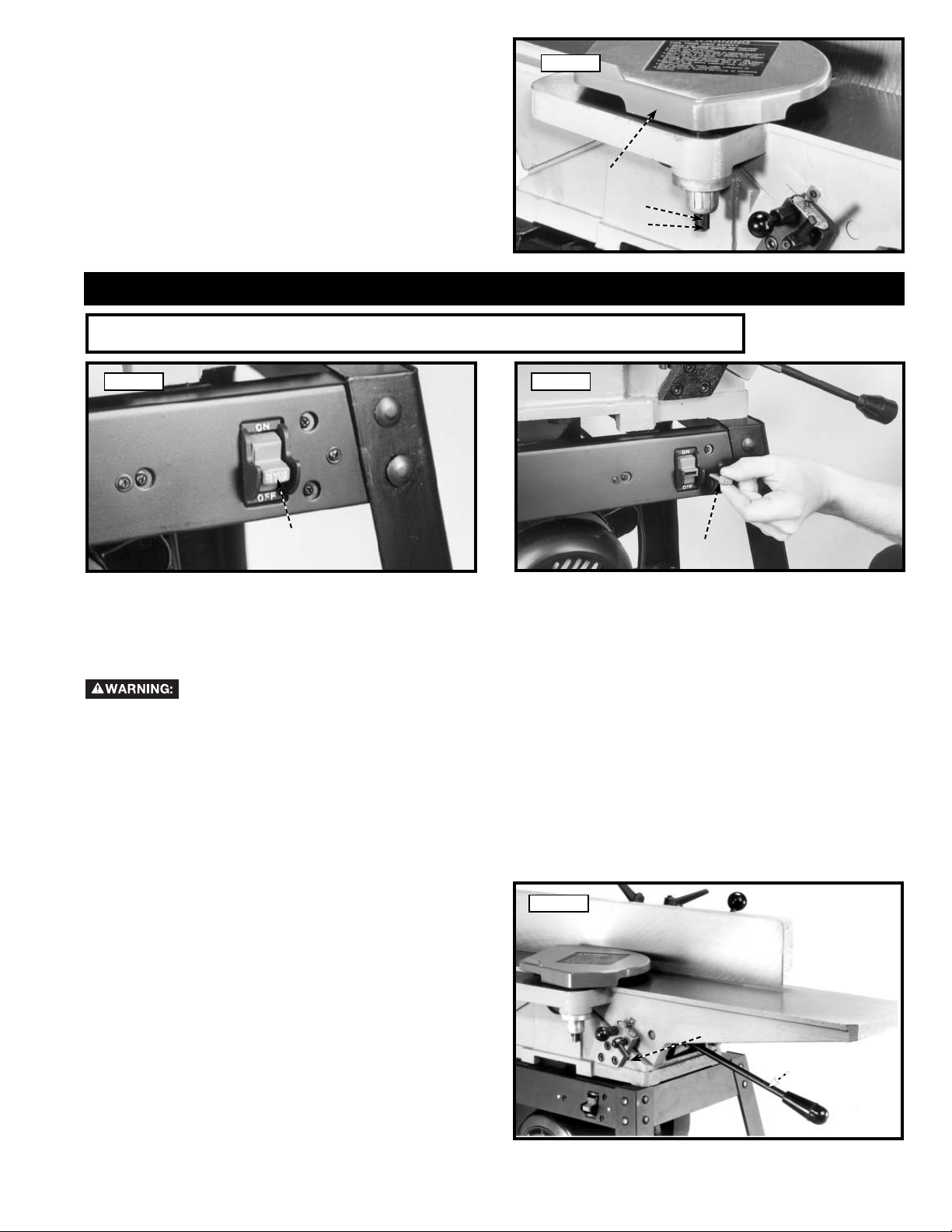
3. Replace set screw (A) Fig. 24, which was removed in
STEP 1.
4. Fig. 24, illustrates the cutterhead guard (C) as sembled to the infeed table.
Fig. 24
C
A
B
OPERATION
OPERATIONAL CONTROLS AND ADJUSTMENTS
Fig. 33 Fig. 34
A
B
STARTING AND STOPPING JOINTER
1. The on/off switch (A) Fig. 33 is located on the front of the jointer. To turn the machine "ON", move switch (A) up
to the "ON" position.
2. To turn the machine "OFF", move the switch down to the "OFF" position.
Make sure that the switch is in the "OFF" position before plugging in the power cord. In the
event of a power failure, move the switch to the "OFF" position. An accidental start-up can cause injury.
LOCKING SWITCH IN THE "OFF" POSITION
IMPORTANT: When the tool is not in use, the switch should be locked in the "OFF" position to prevent
unauthorized use. To lock the switch, grasp the switch toggle (A) Fig. 33 and pull it out of the switch. With the switch
toggle (B) Fig. 34 removed, the switch will not operate. However, should the switch toggle be removed while the saw
is running, the machine can be turned "OFF," but cannot be restarted without re-inserting the switch toggle (B).
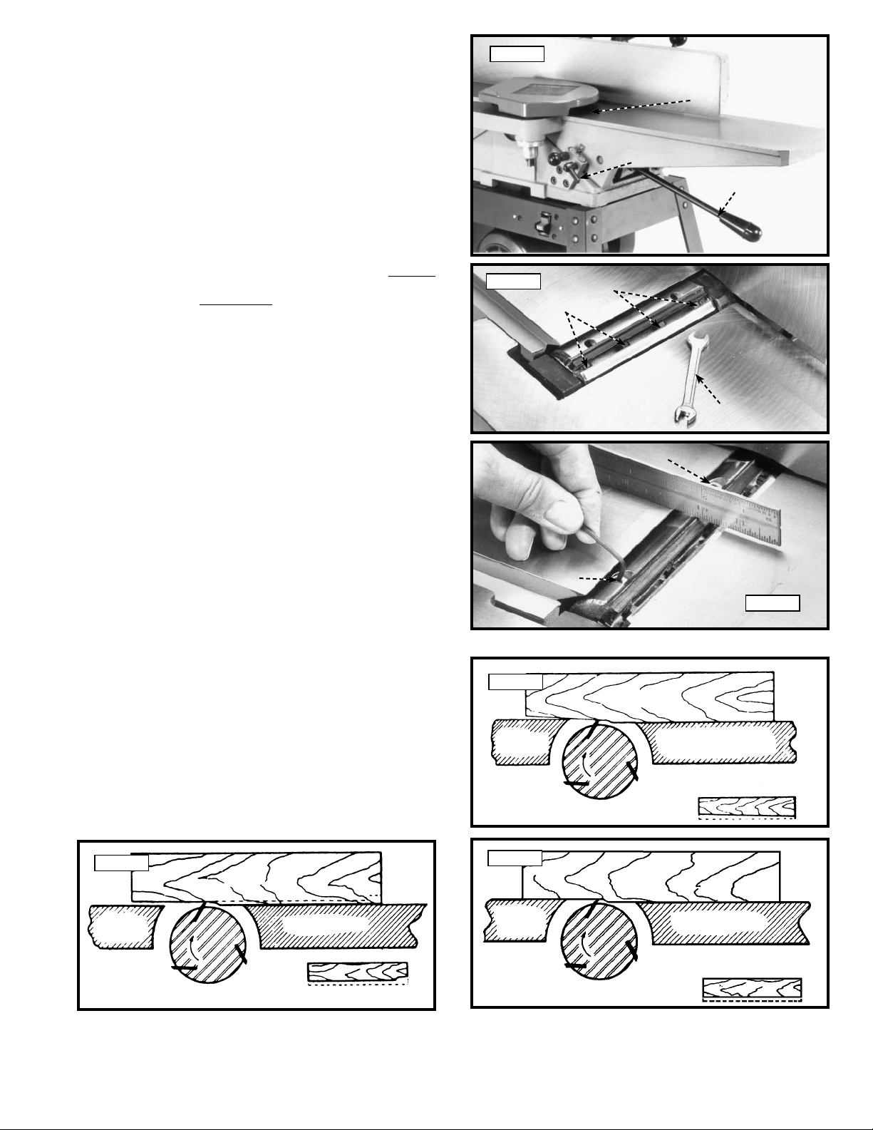
INFEED TABLE ADJUSTMENTS
1. To raise or lower the infeed table, loosen table
lockhandle (A) Fig. 35, move the table raising and
lowering handle (B) up or down until the table is at
the desired position and tighten table lockhandle (A).
Fig. 35
15 - English
A
B
Page 16
2. NOTE: When raising or lowering the infeed
table a plunger located on other end of
the index stop (C) Fig. 36, automatically
stops the table at 1/8 inch depth of cut.
To move the table past this point it is necessary to pull
out index stop (C) and move the table up or down.
IMPORTANT: Always make sure table lockhandle (A)
is tightened before op er a tion. The table lockhandle
(A) is spring-loaded and can be repositioned by
pulling out the handle and repositioning it on the
serrated nut located under the handle.
3. The depth of cut of the infeed table (position of table
in relationship with the cutting circle) can be read with
the pointer (D) Fig. 36, and scale (E). Maximum table
depth adjustment with this 6" jointer is 1/2 inch.
Fig. 36
C
D
E
A
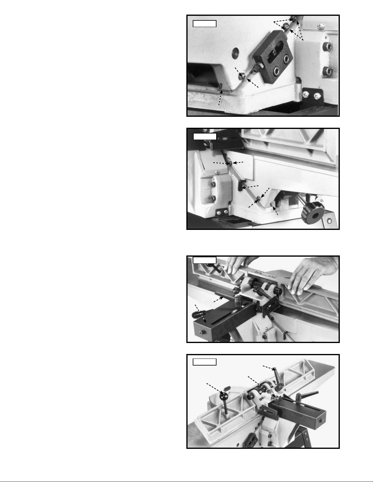
INFEED TABLE POSITIVE STOPS
Positive stops are provided to limit the height and depth of
the infeed table. To adjust the stops, loosen two locknuts
(F) and (G) Fig. 37, and turn the two adjusting screws (J)
and (K) as required. Then retighten the locknuts (F) and
(G). A good suggestion is to set the upper positive stop
(J) for your finish or final cut. This means that you will be
able to rapidly set the infeed table for a finish or final cut
without checking the scale and pointer. Also the lower
positive stop (K) can be set for the maximum 1/2" depth
of cut or if you desire to limit the depth of cut, adjust the
stop screw (K) accordingly.
OUTFEED TABLE ADJUSTMENTS
For most jointing operations the outfeed table must
be level with the knives at their highest point of
revolution. This means that the knives must be parallel to
the outfeed table and project equally from the cutterhead.
To move the outfeed table up or down, loosen lockscrew
(A) Fig. 38, and turn hand knob (B). When the outfeed
table is level with the knives at their highest point of
revolution, tighten lockscrew (A).
Fig. 37
J
F
G
K
Fig. 38
A
B
KNIFE AND OUTFEED TABLE
ADJUSTMENTS
In order to do accurate work, the knives must be exactly
level with the outfeed table. To check and adjust,
proceed as follows:
1. Disconnect machine from power
source.
2. Loosen lock lever (A) Fig. 40, and lower the
infeed table by pushing handle (B) down. Remove
cutterhead guard (C).
3. Place a straight edge on the outfeed table, extending
over the cutterhead as shown in Fig. 39 and 42.
16 - English
STEEL STRAIGHT EDGE
OUT-FEED TABLE
Fig. 39
CUTTER
IN-FEED
TABLE
Page 17
4. CAREFULLY rotate the cutterhead by turning the belt
by hand. The knives should just touch the straight
edge.
Fig. 40
C
A
B
5. If the knife is high or low at either end, slightly
turn the four screws (D) Fig. 41, in the knife
locking bar clockwise to loosen using the
wrench (E) supplied. Then adjust the height of
the knife by turning the knife raising screws (F)
Fig. 42, counterclockwise to lower and clockwise to
raise the knife.
NOTE: If the knife is to be lowered it will be necessary to
wear protective gloves and carefully push down on the
knife with a piece of scrap wood after screws (F) have
been turned.
6. Repeat these procedures for adjusting the remaining
two knives.
7. If the knives are set too low, the result will be as
shown in Fig. 43, and the finished surface will be
curved.
8. If the knives are set too high, the work will be gouged
at the end of the cut, as shown in Fig. 44.
9. As a final check, run a piece of work slowly over the
knives for 6 to 8 inches. The wood should rest firmly
on both tables as shown in Fig. 45, with no open
spaces under the finished cut.
Fig. 41
D
F
Fig. 43
OUT-FEED
TABLE
KNIVES
SET TOO LOW
D
E
F
Fig. 42
WORK
IN-FEED TABLE
CUTTER
Fig. 44
OUT-FEED
TABLE
KNIVES
SET TOO HIGH
WORK
CUTTER
IN-FEED TABLE
17 - English
Fig. 45
OUT-FEED
TABLE
KNIVES AT
CORRECT HEIGHT
WORK
IN-FEED TABLE
CUTTER
Page 18
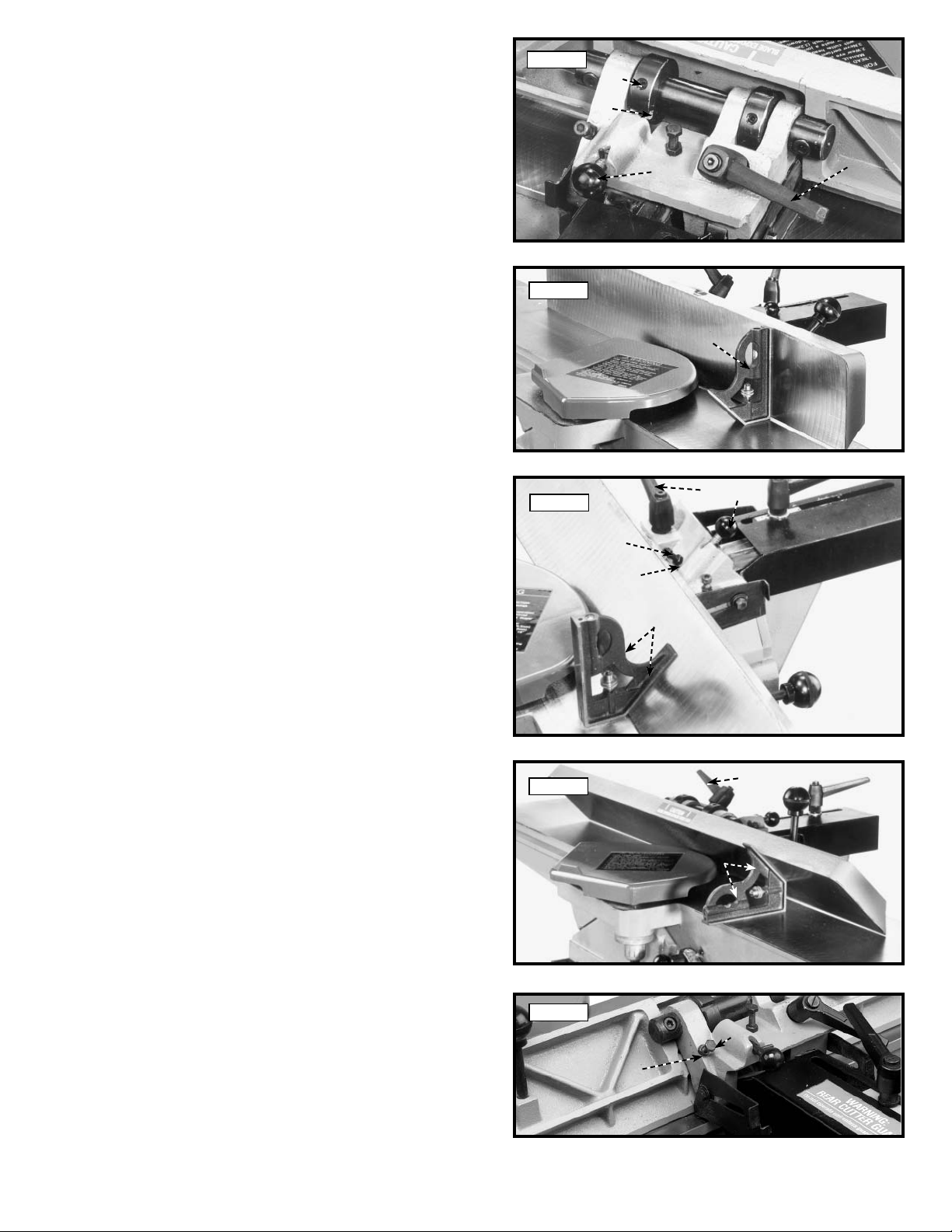
ADJUSTING TABLE GIBS
"Gibs" are provided to take up all play between the mating
dovetail ways of the base and the infeed and outfeed
tables. The "gib" for the infeed table is shown at (A) Fig.
46, and the "gib" for the outfeed table is shown at (B) Fig.
47. Proper "gib" adjustment is necessary for the correct
func tion ing of the jointer. The "gibs" were adjusted at
the factory and should require no further adjustment. If
it becomes necessary to adjust the "gibs", proceed as
follows:
1. To adjust the infeed or outfeed table "gibs," loosen
three locknuts (F) Fig. 46, for the infeed table or two
locknuts (G) Fig. 47, for the outfeed table.
For the infeed table, make sure the table
locking lever is loose. For the outfeed
table, make sure the table locking screw (E)
Fig. 47, is loose.
2. Tighten or loosen three gib adjustment screws (C)
Fig. 46, as necessary for the infeed table or two gib
adjustment screws (D) Fig. 47, as necessary for the
outfeed table; starting with the lower screw first and
as you proceed to the top screw, gently raise the
outboard edge of the table that is being adjusted.
This will offset any ten den cy for the table casting to
"droop or sag" and permit the gib to be adjusted to a
secure fit. After the gibs have been adjusted, tighten
locknuts (F) Fig. 46, (G) Fig. 47, table locking screw
(E) Fig. 47, and infeed table locking lever.
IMPORTANT: Do not leave the adjusting screws too loose.
It should take a little bit of effort to move the tables up
or down. Jointers are finishing machines and you can’t
expect proper accuracy or finish if the tables are not set
properly.
Fig. 46
Fig. 47
D
F
C
F
C
A
G
E
G
D
B
FENCE OPERATION
The fence can be moved across the table and can tilt
45 degrees right or left at any position on the table as
follows:
1. To move the fence across the table, loosen lock
handle (A) Fig. 48, slide fence to the desired position
on the table and tighten lockhandle (A). As the fence
is moved across the table, the rear cutterhead guard
(B) covers and guards the cutterhead in back of the
fence. NOTE: Lock handle (A) is spring-loaded and
can be repositioned by pulling up on the handle
and repositioning it on the serrated nut located
underneath the hub of the handle.
2. To tilt the fence to the right or left loosen lock
handle (C) Fig. 49, and pull out and turn plunger
(D) to release the positive stop. A tilting lever (E) is
provided on the back of the fence to assist in tilting
the fence. NOTE: Lock handle (C) is spring-loaded
and can be repositioned by pulling out the handle
and repositioning it on the serrated nut located
underneath the hub of the handle.
3. Tilt the fence to the desired angle, in or out, and
tighten lock handle (C) Fig. 49. IMPORTANT: When
cutting bevels and the angle is small there is little
difference whether the fence is tilted in or out;
however, at angles approaching 45 degrees it may
become difficult to hold the work securely against
the fence when the fence is tilted out. In these cases
we suggest that the fence be tilted toward the table,
as shown in Fig. 49. The fence will form a V-shape
with the tables and the work is easily pressed into the
pocket while passing across the knives.
18 - English
Fig. 48
B
Fig. 49
E
A
C
D
Page 19
ADJUSTING FENCE POSITIVE STOPS
The fence on this jointer is equipped with positive stops
that allow you to rapidly tilt the fence to the 90 and
45 degree angle to the table in the inward or outward
position. To check and adjust the positive stops, proceed
as follows:
1. Position the fence at 90 degrees to the table. Make
certain the end of plunger (A) Fig. 50, is engaged
in notch (B) in index collar as shown, and tighten
lockhandle (C).
Fig. 50
E
B
A
C
2. Place a square (D) Fig. 51, on the table and against
the fence and check if fence is 90 degrees to table.
3. If an adjustment is necessary, loosen set screw (E)
Fig. 50, in the index collar and loosen fence locking
handle (C).
4. Using the 90 degree edge of the square, tilt the fence
until you are certain the fence is 90 degrees to the
table and tighten lockhandle (C) Fig. 50, and set
screw (E).
5. Loosen lockhandle (C) Fig. 52, pull out and turn
plunger (A) and tilt fence out as far as it will go. Then
tighten lock handle (C).
6. Using square (D) Fig. 52, check to see if the fence
is at a 45 degree outward angle from the table, as
shown.
7. If an adjustment is necessary, loosen lockhandle (C)
Fig. 52. Loosen locknut (F) and turn adjusting screw
(G) until fence is tilted 45 degrees outward. Then
tighten locknut (F).
Fig. 51
Fig. 52
D
C
A
G
F
D
8. Loosen lockhandle (C) Fig. 53, and tilt fence inward
as far as possible, as shown, and tighten lockhandle
(C).
9. Using a square (D) Fig. 53, check to see if the fence
is at a 45 degree inward angle to the table, as shown.
10. If an adjustment is necessary loosen locknut (J)
Fig. 54, and turn adjusting screw (H) until fence is
tilted 45 degrees in. Then tighten lock nut (J).
19 - English
Fig. 53
Fig. 54
C
D
H
J
Page 20
ADJUSTING FENCE GUARDS
Two guards, one of which is shown at (A) Fig. 55, are provided on each side of the fence bracket to close up the opening
between the fence bracket (B) and the fence (C) limiting access to the cutterhead. When the fence is tilted, the guard
(A) Fig. 56, can be pushed to the rear as shown. After the fence is returned to the 90 degree position, push the guard
(A) Fig. 56, forward to close up the opening. Fig. 55, illustrates the guard (A) properly adjusted.
Fig. 55
B
A
C
Fig. 56
A
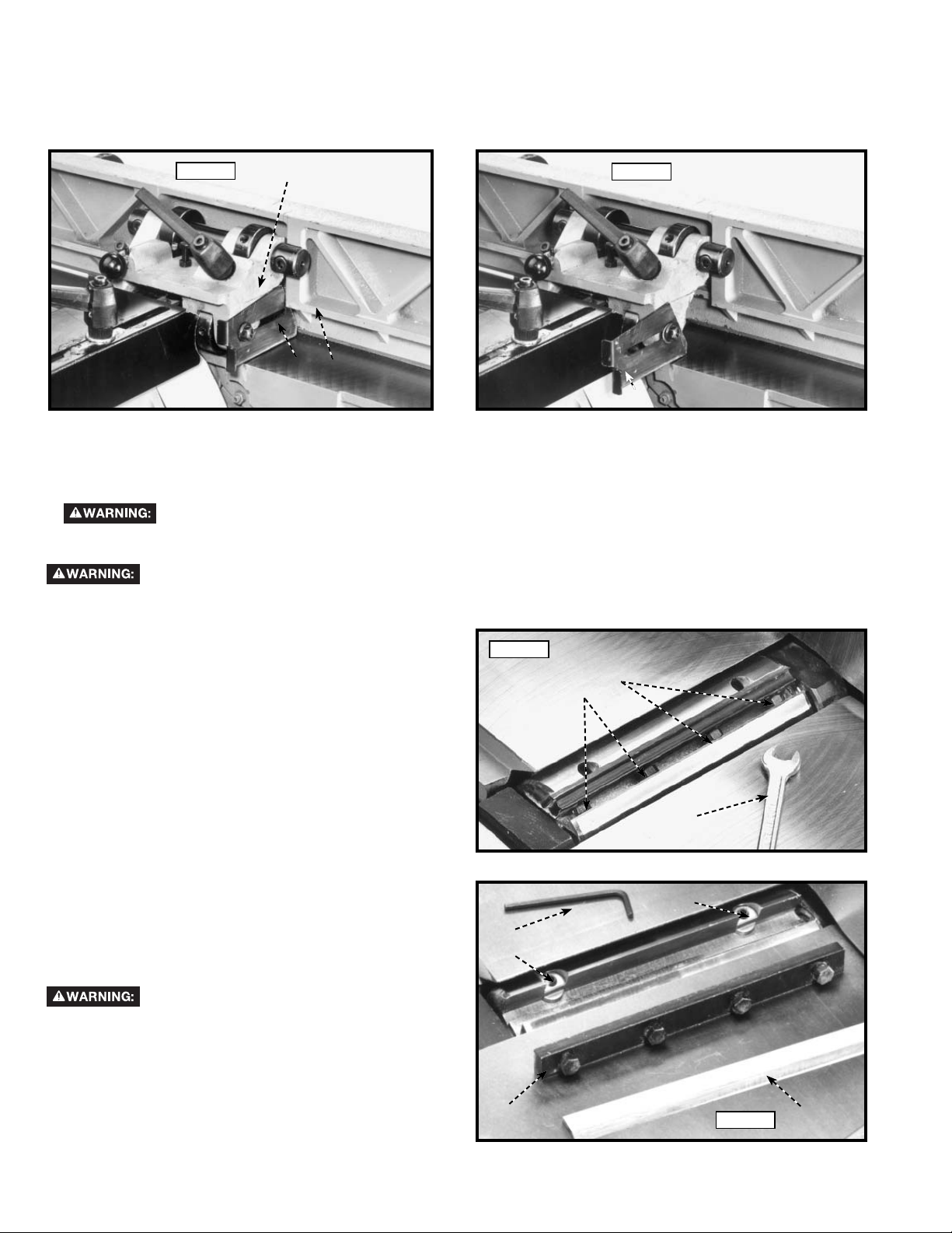
REPLACING AND RESETTING KNIVES
If the knives are removed from the cutterhead for re place ment or sharpening, care must be used in removing, re plac ing
and resetting them. Proceed as follows:
1. Disconnect machine from power source.
2. Move the fence to the rear and remove the cutterhead guard (C) Fig. 40.
Be extremely careful that your hands do not come in contact with the knives.
3. Using 8x10 mm open end wrench (A) Fig. 57, slightly
loosen the four locking screws (B) in each knife slot
by turning the screws (B) clockwise. This relieves
stress in the cutterhead.
4. Loosen screws (B) Fig. 57, further and remove knife
and knife locking bar.
5. Fig. 58, illustrates the knife (C) and knife locking
bar (D) removed from the cutterhead. Remove the
remaining two knives and locking bars, in the same
manner.
6. Using the 2.5mm allen wrench (E) Fig. 58, lower the
two knife ad just ment blocks by turning screws (F)
counterclockwise in all three slots of the cutterhead.
7. Before replacing knives make certain the knife locking
bars are thoroughly clean and free of gum and pitch.
8. Place the knife locking bars (D) Fig. 58, and knives (C)
into each slot in the cutterhead.
Fig. 57
E
F
B
B
B
A
F
CARE MUST BE TAKEN WHEN INSERT-
ING THE KNIVES AS THE CUTTING
EDGES ARE VERY SHARP. Push the knife down using a scrap piece of wood as far as possible and turn
each screw (B) Fig. 57, counterclockwise just enough
to hold the knife in position. Replace the remaining
two knives in the same manner. NOTE: Knives must
be installed correctly as shown in Fig. 59.
20 - English
D
Fig. 58
C
Page 21
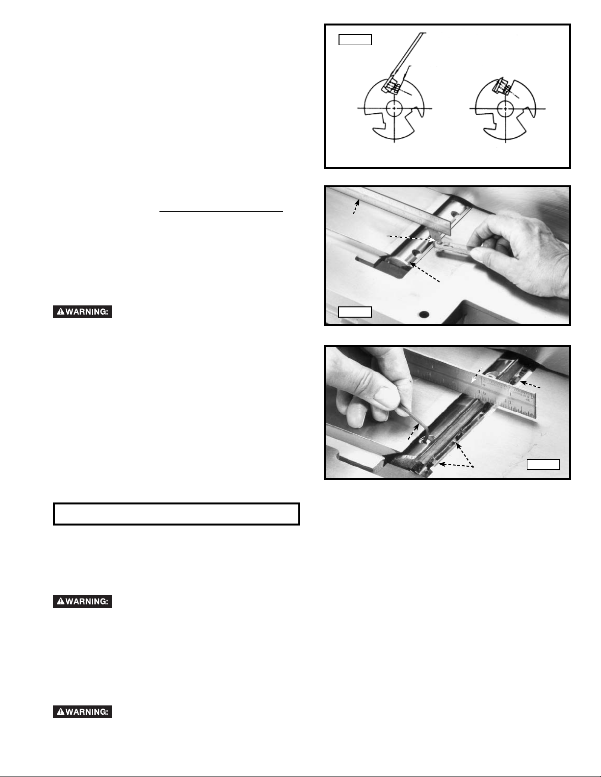
9. The knives are adjusted correctly when the cutting
edge of the knife extends out .060" (1.5 mm) from the
cutterhead diameter.
10. Carefully rotate the cutterhead (G) Fig. 60, until the
round portion of the cutterhead is on top as shown.
11. Place a .060" (1.5 mm) feeler gage (H) Fig. 60, on the
cutterhead and using a straight edge (J) on the rear
table adjust the height of the rear table until it is .060"
(1.5 mm) above the cuttinghead diameter.
12. Lock the rear table in position and remove the feeler
gage.
13. Lower the infeed table and place a straight edge
(J) Fig. 61, on the outfeed table extending over the
cutterhead as shown.
14. Rotate the cutterhead by hand until the knife is at
its highest point at each end of the cutterhead. To
raise the knife, use wrench (E) Fig. 61, and turn
raising screw clock wise until the knife just touches
the straight edge (J) on each end and center of the
cutterhead when the knife is at its highest point.
When you are certain the knife is adjusted properly,
tighten the four locking screws (B) by turning them
counterclockwise.
15. Adjust the remaining two knives in the same manner.
Make certain that all knives are secure-
ly fastened in cutterhead before turning on power.
16. Replace cutterhead guard.
Fig. 59
DO
WARNING: Insure cutter blades are installed properly
Mating surfaces of cutterhead to blade
and blade to bar to be tight and parallel
Face of screw and face of cutterhead
to be parallel
J
H
G
Fig. 60
DON’T
J
B
E
Fig. 61
B
MACHINE USE
The following directions will give the beginner a start on jointer operations. Use scrap pieces of lumber to check settings
and to get the feel of the operations before attempting regular work.
NOTE: The knives on the jointer will not wear evenly by feeding the through the same spot on the table every
time. Feed the wood through the jointer at different spots on the table when possible, to help eliminate uneven
wear of the knives.
Always use cutterhead guard and keep hands away from cutterhead. Always use push blocks
whenever possible. Never make jointing and planning cuts deeper than 1/8" in one pass.
PLACEMENT OF HANDS DURING FEEDING
At the start of the cut, the left hand holds the work firmly against the infeed table and fence, while the right hand pushes
the work toward the knives. After the cut is un der way, the new surface rests firmly on the outfeed table as shown in
Fig. 64. The left hand should then be moved to the work on the outfeed table, at the same time maintaining flat contact
with the fence. The right hand presses the work forward, and before the right hand reaches the cutterhead, it should
be moved to the work on the outfeed table.
Never pass hands directly over the cutterhead.
21 - English
Page 22
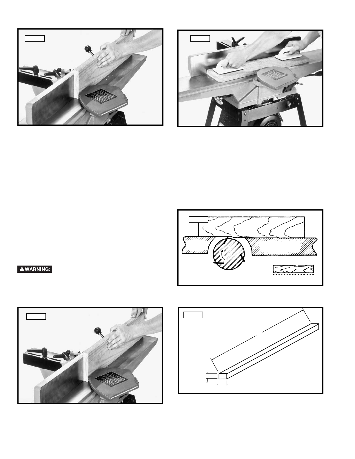
DEFINITIONS OF JOINTING AND PLANING OPERATIONS
Fig. 63Fig. 62
1. JOINTING OPERATIONS – Jointing cuts or edge
jointing are made to square an edge of a workpiece.
The workpiece is positioned on the jointer with the
narrow edge of the workpiece on the infeed table and
the major flat surface of the workpiece against the
fence, as shown in Fig. 62. The workpiece is moved
from the infeed table, across the cutterhead to the
outfeed table.
JOINTING AN EDGE
This is the most common operation for the jointer. Set
the guide fence square with the table. Depth of cut
should be the minimum required to obtain a straight
edge. Hold the best face of the piece firmly against the
fence throughout the feed as shown in Fig. 65. Maximum
depth of cut should not be more than 1/8" (3.175 mm)
in one pass.
Do not perform jointing operations on
material shorter than 10" (254 mm), narrower than
3/4" (19 mm), or less that 1/2" (12.7 mm) thick. See
Fig. 66.
2. PLANING OPERATIONS – Planing or surfacing
are identical to the jointing operation except for the
position of the workpiece. For planing, the major
flat surface of the workpiece is placed on the
infeed table of the jointer with the narrow edge of
the workpiece against the fence, as shown in Fig.
63. The workpiece is moved from the infeed table,
across the cutterhead to the outfeed table. Use push
blocks when performing planing operations whenever
possible.
Fig. 64
WORK
OUT-FEED
TABLE
CUTTER
IN-FEED TABLE
Fig. 65
22 - English
Fig. 66
MINIMUM JOINTING
DIMENSIONS
1/2" (12.7 mm)
MIN I MUM
10" (254 mm) MINIMUM
3/4" (19 mm) MIN I MUM
Page 23
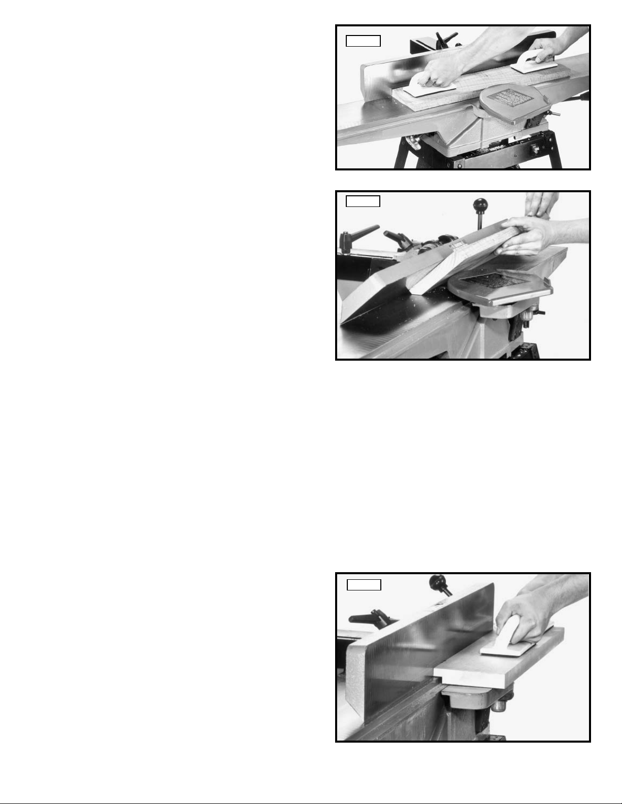
PLANING OR SURFACING
Planing or surfacing is identical to the jointing operation
except for the position of the workpiece. For planing, the
major flat surface of the workpiece is placed on the infeed
table of the jointer with the narrow edge of the workpiece
against the fence, a shown in Fig. 67. The workpiece is
moved from the infeed table, across the cutterhead to the
outfeed table establishing a flat surface on the workpiece
Always use push blocks when performing planing op era tions and never pass your hands directly over the
cutterhead. Maximum depth of cut should not be more
than 1/8" in one pass.
Fig. 67
BEVELING
To cut a bevel, lock the fence at the required angle and
run the work across the knives while keeping the work
firmly against the fence and tables. Several passes may
be necessary to arrive at the desired result. When the
angle is small, there is little difference whether the fence
is tilted to the right or left. However, at greater angles
approaching 45 degrees, it is increasingly difficult to hold
the work properly when the fence is tilted to the right.
The advantage of the double-tilting fence is appreciated
under such conditions.
When tilted to the left, the fence forms a V-shape with
the tables, and the work is easily pressed into the pocket
while passing it across the knives as shown in Fig. 68. If
the bevel is laid out on the piece in such direction that
this involves cutting against the grain, it will be better to
tilt the fence to the right.
Fig. 68
TAPER CUTS
One of the most useful jointer operations is cutting an edge to a taper. This method can be used on a wide variety of
work. Tapered legs of furniture are a common example.
Instead of laying the piece on the infeed table, lower the forward end of the work onto the outfeed table. Do this very
carefully, as the piece will span the knives, and they will take a "bite" from the work with a tendency to kick back unless
the piece is firmly held. Now push the work forward as in ordinary jointing. The effect is to plane off all the stock in front
of the knives, to increasing depth, leaving a tapered surface.
The ridge left by the knives when starting the taper may be removed by taking a very light cut according to the regular
method for jointing, with the infeed table raised to its usual position.
Practice is required in this operation, and the beginner is advised to make trial cuts on waste material. Taper cuts over
part of the length and a number of other special operations can easily be done by the experienced crafts man.
CUTTING A RABBET
When making a rabbet cut, as shown in Fig. 69,
the cutterhead guard must be removed. AFTER THE
RABBET CUT IS COM PLET ED, BE CERTAIN GUARD
IS REPLACED.
1. Adjust the fence so that the distance between the
end of the knives and the fence is equal to the width
of the rabbet.
2. Lower the infeed table an amount equal to the depth
of the rabbet. If the rabbet is quite deep, it may be
necessary to cut it in two or more passes. In that
event, the table is lowered an amount equal to about
half the depth of the rabbet for the first pass, then
lowered again to proper depth to complete the cut.
Maximum depth of cut when rabbeting with this
jointer is 1/2 inch.
23 - English
Fig. 69
Page 24

PLANING WARPED PIECES
If the wood to be planed is dished or warped, take light
cuts until the surface is flat. Avoid forcing such material
down against the table; excessive pressure will spring
it while passing the knives, and it will spring back and
remain curved after the cut is completed.
PLANING SHORT OR THIN WORK
When planing short or thin pieces, always use push
blocks to minimize all danger to the hands. Fig. 70,
illustrates using the Delta Push Blocks properly.
Do not perform planning operations on
materials shorter than 10 inches (254 mm), narrower
than 3/4 inch (19 mm), wider than 6 inches (152.4 mm)
or less than 1/2 inch (12.7 mm) thick. See Fig. 71
Fig. 70
DIRECTION OF GRAIN
Avoid feeding work into the jointer against the grain
as shown in Fig. 72. The result will be chipped and
splintered edges. Feed with the grain as shown in Fig.
73, to obtain a smooth surface.
MINIMUM AND
MAXIMUM
PLANING
DIMENSIONS
1/2" (12.7 mm)
MINIMUM
10" (254 mm) MINIMUM
3/4" (19mm) MINIMUM
6" (152.4 mm)
MAXIMUM
Fig. 71
Fig. 72
OUT-FEED
TABLE
CUTTER
IN-FEED TABLE
WRONG FEED - AGAINST THE GRAIN
Fig. 73
OUT-FEED
TABLE
CUTTER
IN-FEED TA BLE
CORRECT FEED - WITH THE GRAIN
TROUBLESHOOTING
For assistance with your machine, visit our website at www.deltamachinery.com for a list of service centers or call
the DELTA Machinery help line at 1-800-223-7278 (In Canada call 1-800-463-3582).
24 - English
Page 25

MAINTENANCE
After considerable use, the knives will become dull and it will not be possible to do accurate work. Unless badly
damaged by running into metal or other hard material, the knives may be sharpened as follows:
WHETTING KNIVES
Disconnect machine from power
source.
Use a fine carborundum stone, cover it partly with paper
as indicated in Fig. 74 to avoid marking the table. Lay
the stone on the infeed table, lower the table and turn
the cutterhead forward until the stone lies flat on the
bevel of the knife as shown. Hold the cutterhead from
turning, and whet the beveled edge of the knife, stroking
lengthwise by sliding the stone back and forth across the
table. Do the same amount of whetting on each of the
three knives.
REMOVING DUST CHUTE COVER
The dust chute cover (A) Fig. 75, can be removed, for
cleaning purposes, by removing the two wing screws
(B).
Fig. 74
OUT-FEED
TABLE
Fig.75
OILSTONE PARTLY
COVERED WITH PAPER
IN-FEED TABLE
CUTTER
WHETTING KNIVES
Make certain the machine is
disconnected from the power source before removing
the dust chute cover. The dust chute cover (A) must
always be assembled to the dust chute during
operation.
B
KEEP MACHINE CLEAN
Periodically blow out all air passages with dry compressed air. All plastic parts should be cleaned with a soft damp cloth.
NEVER use solvents to clean plastic parts. They could possibly dissolve or otherwise damage the material.
Wear certified safety equipment for eye, hearing and respiratory protection while using compressed air.
FAILURE TO START
Should your machine fail to start, check to make sure the prongs on the cord plug are making good contact in the
outlet. Also, check for blown fuses or open circuit breakers in the line.
LUBRICATION & RUST PROTECTION
Apply household floor paste wax to the machine table, extension table or other work surface weekly. Or use a commercially
available protective product designed for this purpose. Follow the manufacturer’s instructions for use and safety.
To clean cast iron tables of rust, you will need the following materials: a sheet of medium Scotch-Brite™ Blending Hand
Pad, a can of WD-40® and a can of degreaser. Apply the WD-40 and polish the table surface with the Scotch-Brite pad.
Degrease the table, then apply the protective product as described above.
SERVICE
REPLACEMENT PARTS
Use only identical replacement parts. For a parts list or to order parts, visit our website at
can also order parts from your nearest factory-owned branch, or by calling our Customer Care Center at 1-800-223-7278 to
receive personalized support from highly-trained technicians.
25 - English
servicenet.deltamachinery.com.
You
Page 26

FREE WARNING LABEL REPLACEMENT
If your warning labels become illegible or are missing, call
TO REDUCE THE RISK OF INJURY USER MUST READ THE INSTRUCTION
MANUAL BEFORE OPERATING JOINTER. ALWAYS WEAR PROPER EYE AND
RESPIRATORY PROTECTION. WHEN OPERATING THIS TOOL, DO NOT WEAR GLOVES, NECKTIES, JEWELRY, LOOSE
CLOTHING OR LONG HAIR. LACERATION HAZARD. ALWAYS KEEP HANDS AND FINGERS AWAY FROM
CUTTERHEAD. NEVER PERFORM A JOINTING OR PLANING OPERATION WITH CUTTERHEAD OR DRIVE GUARD
REMOVED. DISCONNECT MACHINE FROM POWER SOURCE BEFORE MAKING REPAIRS OR ADJUSTMENTS. ALWAYS
USE HOLD DOWNS OR PUSH BLOCK FOR JOINTING MATERIAL NARROWER THAN 3 INCHES (76.2 MM) OR
PLANING MATERIAL THINNER THAN 3 INCHES (76.2 MM). KICKBACK HAZARD. NEVER JOINT OR PLANE
MATERIAL LESS THAN 10 INCHES (254 MM) LONG. NEVER MAKE A JOINTING OR PLANING CUT DEEPER THAN 1/8
INCH (3.2 MM). SHOCK HAZARD. DO NOT EXPOSE TO RAIN OR USE IN DAMP LOCATIONS. DO NOT OPERATE
WHILE UNDER THE INFLUENCE OF DRUGS, ALCOHOL OR MEDICATION.
SIEMPRE UTILICE PROTECCIÓN ADECUADA PARA LOS OJOS Y VÍAS RESPIRATORIAS. CUANDO OPERE ESTA
HERRAMIENTA, NO UTILICE GUANTES, CORBATAS, JOYAS, ROPA HOLGADA NI EL CABELLO LARGO SUELTO.
PELIGRO DE LACERACIÓN. SIEMPRE MANTENGA LAS MANOS Y LOS DEDOS ALEJADOS DEL CABEZAL DE CORTE.
NUNCA REALICE UN ENSAMBLE O UNA OPERACIÓN DE CEPILLADO SIN EL CABEZAL DE CORTE O LA GUARDA DE
IMPULSO COLOCADOS. DESCONECTE LA MÁQUINA DE LA FUENTE DE ALIMENTACIÓN ANTES DE REALIZAR
REPARACIONES O AJUSTES. SIEMPRE UTILICE PLANTILLAS DE GUÍA O BLOQUES DE EMPUJE PARA EL MATERIAL
DE ENSAMBLE MÁS ANGOSTO QUE 76,2 MM (3 PULG) O CEPILLADO DE MATERIAL MÁS FINO QUE 76,2 MM (3
PULG). RIESGO DURANTE EL RETROCESO. NUNCA ENSAMBLE O CEPILLE MATERIAL DE MENOS DE 254 MM (10
PULG) DE LARGO. NUNCA REALICE UN CORTE EMPALMADO O CEPILLADO MÁS PROFUNDO QUE 3,2 MM (1/8
PULG). RIESGO DE DESCARGA ELÉCTRICA. NO EXPONGA A LA LLUVIA NI UTILICE EN LUGARES HÚMEDOS. NO
OPERE BAJO LA INFLUENCIA DE DROGAS, ALCOHOL O MEDICACIÓN.
RISQUE DE BLESSURE. TOUJOURS PORTER UNE PROTECTION OCULAIRE ET RESPIRATOIRE ADÉQUATE. NE PAS
PORTER DE GANTS, NI CRAVATES, NI BIJOUX OU VÊTEMENTS AMPLES ET COUVRIR LES CHEVEUX LONGS LORS DE
L’UTILISATION DE L’OUTIL. RISQUE DE LACÉRATION. TOUJOURS ÉLOIGNER LES MAINS ET LES DOIGTS DE LA
TÊTE DE COUPE. NE JAMAIS DÉGAUCHIR OU RABOTER SANS LE DISPOSITIF DE PROTECTION DE LA TÊTE DE
COUPE OU DU SYSTÈME D’ENTRAÎNEMENT. DÉBRANCHER LA MACHINE DE LA SOURCE D’ALIMENTATION AVANT
D’EFFECTUER DES RÉPARATIONS OU DES RÉGLAGES. TOUJOURS UTILISER UN MODULE D’ANCRAGE OU DES
BLOCS-POUSSOIRS POUR DÉGAUCHIR DES PIÈCES PLUS ÉTROITE QUE 76,2 MM (3 PO) OU RABOTER DES PIÈCES
PLUS MINCES QUE 76,2 MM (3 PO). RISQUE DE REBOND. NE JAMAIS DÉGAUCHIR OU RABOTER DES PIÈCES PLUS
COURTES QUE 254 MM (10 PO) DE LONG. NE JAMAIS ENLEVER PLUS DE 3,2 MM (1/8 PO) DE MATÉRIEL AVEC LA
DÉGAUCHISSEUSE OU LA RABOTEUSE. RISQUE DE CHOC ÉLECTRIQUE. NE L’EXPOSER À LA PLUIE ET NE PAS
L’UTILISER DANS UN ENDROIT HUMIDE. NE PAS UTILISER L’APPAREIL SOUS L’EMPRISE DE DROGUES, D’ALCOOL
OU DE MÉDICAMENT.
PARA REDUCIR EL RIESGO DE LESIONES, EL USUARIO DEBE LEER EL
MANUAL DE INSTRUCCIONES ANTES DE OPERAR LA EMPALMADORA.
L’UTILISATEUR DOIT LIRE LE MODE D’EMPLOI AVANT
D’UTILISER LA DÉGAUCHISSEUSE AFIN DE RÉDUIRE LE
A16033
1-800-223-7278
LACERATION
HAZARD.
KEEP HANDS
OUT OF
DUST CHUTE.
LACERATION
HAZARD.
DO NOT OPERATE JOINTER
UNLESS GUARD
IS IN PLACE.
for a free replacement.
PELIGRO DE
LACERACIÓN.
MANTEGA LAS MANOS
FUERA DEL CONDUCTO
PARA POLVO.
PELIGRO DE
LACERACIÓN.
NO OPERE LA EMPALMADORA
A MENOS QUE LA GUARDA
ESTÉ EN SU LUGAR.
RISQUE DE
LACÉRATION.
ÉLOIGNER LES MAINS
DE LA GOULOTTE
DE POUSSIÈRE.
RISQUE DE
LACÉRATION.
NE PAS UTILISER LA
DÉGAUCHISSEUSE SANS LE
DISPOSITIF DE PROTECTION EN PLACE.
A16201
A16970
SERVICE AND REPAIRS
All quality tools will eventually require servicing and/or replacement of parts. For information about Delta Machinery, its factoryowned branches, or an Authorized Warranty Service Center, visit our website at www.deltamachinery.com or call our Customer
Care Center at 1-800-223-7278. All repairs made by our service centers are fully guaranteed against defective material and
workmanship. We cannot guarantee repairs made or attempted by others.
You can also write to us for information at Delta Machinery, 4825 Highway 45 North, Jackson, Tennessee 38305 - Attention:
Product Service. Be sure to include all of the information shown on the nameplate of your tool (model number, type, serial number,
etc.)
ACCESSORIES
A complete line of accessories is available from your Delta Supplier, Porter-Cable • Delta Factory Service Centers, and
Delta Authorized Service Stations. Please visit our Web Site www.deltamachinery.com for a catalog or for the name of
your nearest supplier.
Since accessories other than those offered by Delta have not been tested with this product, use
of such accessories could be hazardous. For safest operation, only Delta recommended accessories should be
used with this product. used with this product.
WARRANTY
To register your tool for warranty service visit our website at www.deltamachinery.com.
Two Year Limited New Product Warranty
Delta will repair or replace, at its expense and at its option, any new Delta machine, machine part, or machine accessory which in normal
use has proven to be defective in workmanship or material, provided that the customer returns the product prepaid to a Delta factory service
center or authorized service station with proof of purchase of the product within two years and provides Delta with reasonable opportunity
to verify the alleged defect by inspection. For all refurbished Delta product, the warranty period is 180 days. Delta may require that electric
motors be returned prepaid to a motor manufacturer’s authorized station for inspection and repair or replacement. Delta will not be responsible
for any asserted defect which has resulted from normal wear, misuse, abuse or repair or alteration made or specifically authorized by anyone
other than an authorized Delta service facility or representative. Under no circumstances will Delta be liable for incidental or consequential
damages resulting from defective products. This warranty is Delta’s sole warranty and sets forth the customer’s exclusive remedy, with respect
to defective products; all other warranties, express or implied, whether of merchantability, fitness for purpose, or otherwise, are expressly
disclaimed by Delta.
26 - English
Page 27

LES INSTRUCTIONS IMPORTANTES DE SURETE
d'utiliser n'importe quel outil ou n'importe quel équipement. En utilisant les outils ou l'équipement,
les précautions de sûreté fondamentales toujours devraient être suivies pour réduire le risque de
blessure personnelle. L'opération déplacée, l'entretien ou la modification d'outils ou d'équipement ont
pour résultat la blessure sérieux et les dommages de propriété. Il y a de certaines applications pour lequel outils et
l'équipement sont conçus. La Delta Machinery recommande avec force que ce produit n'ait pas modifié et/ou utilisé
pour l'application autrement que pour lequel il a été conçu.
Si vous avez n'importe quelles questions relatives à son application n'utilisent pas le produit jusqu'à ce que vous
avez écrit Delta Machinery et nous vous avons conseillé. La forme en ligne de contact à www.deltamachinery.com
Courrier Postal: Technical Service Manager, Delta Machinery, 4825 Highway 45 North, Jackson, TN 38305.
125 Mural St. Suite 300, Richmond Hill, ON, L4B 1M4.
Information en ce qui concerne l'opération sûre et correcte de cet outil est disponible des sources suivantes:
• Power Tool Institute, 1300 Sumner Avenue, Cleveland, OH 44115-2851 ou en ligne www.powertoolinstitute.org
• National Safety Council, 1121 Spring Lake Drive, Itasca, IL 60143-3201
• American National Standards Institute, 25 West 43rd Street, 4 floor, New York, NY 10036 www.ansi.org - ANSI 01.1
Safety Requirements for Woodworking Machines
• U.S. Department of Labor regulations www.osha.gov
Lire et comprendre toutes instructions d'avertissements et opération avant
Dans Canada,
MESURES DE SÉCURITÉ - DÉFINITIONS
Ce guide contient des renseignements importants que vous deviez bien saisir. Cette information porte sur VOTRE SÉCURITÉ
et sur LA PRÉVENTION DE PROBLÈMES D’ÉQUIPEMENT. Afin de vous aider à identifier cette information, nous avons
utilisé les symboles ci-dessous. Veuillez lire attentivement ce guide en portant une attention particulière à ces
sections.
Indique un danger imminent qui, s'il n'est pas évité, causera de graves blessures ou la mort.
ou la mort
dommages; mineures ou moyennes.
.
Indique la possibilité d’un danger qui, s’il n’est pas évité, pourrait causer de graves blessures
Indique la possibilité d’un danger qui, s’il n’est pas évité, peut causer des dommages à la propriété.
S
ans le symbole d’alerte.
Indique la possibilité d'un danger qui, s'il n'est pas évité,
peut causer des
LA PROPOSITION DE CALIFORNIE 65
activités de construction peut contenir des produits chimiques qui sont reconnus, par l'état de la Californie, de causer
le cancer, les anomalies congénitales ou autres maux de reproduction. Ces produits chimiques comprennent, entre
autres :
• le plomb provenant des peintures à base de plomb;
• la silice cristalline provenant de briques, de béton ou d'autres produits de maçonnerie
• l'arsenic et le chrome provenant du bois de charpente traité chimiquement
Le risque d'exposition à ces produits dépend de la fréquence d'exécution de ce genre de travaux. Afin de réduire l'exposition
à ces produits chimiques, travaillez dans un endroit bien aéré et utilisez de l'équipement de sécurité approuvé,
un masque facial ou respirateur homologué MSHA/NIOSH bien ajusté lorsque vous utilisez de tels outils.
La poussière produite par le ponçage électrique le sciage, le meulage, le perçage et autres
portez toujours
CONSERVEZ CES INSTRUCTIONS!
27 - Français
Page 28

RÈGLES DE SÉCURITÉ GÉNÉRALES
L’inobservation de ces règles peut conduire à des blessures graves.
1. POUR SA SÉCURITÉ PERSONNELLE, LIRE LA NOTICE
D’UTILISATION, AVANT DE METTRE LA MACHINE EN
MARCHE, et pour aussi apprendre l’application et les limites de
la machine ainsi que les risques qui lui sont particuliers ainsi, les
possibilités d’accident et de blessures seront beaucoup réduites.
2. PORTEZ DES DISPOSITIFS DE PROTECTION DES YEUX
ET DE L'OUÏE. UTILISEZ TOUJOURS DES LUNETTES DE
SÉCURITÉ. Des lunettes ordinaires ne constituent PAS des
lunettes de sécurité. UTILISEZ DES ÉQUIPEMENTS DE
SÛRETÉ HOMOLOGUÉS. Les dispositifs de protection des yeux
doivent être conformes aux normes ANSI Z87.1. Les dispositifs
de protection de l'ouïe doivent être conformes aux normes ANSI
S3.19.
3. PORTER UNE TENUE APPROPRIÉE. Pas de cravates, de
gants, ni de vêtements amples. Enlever montre, bagues et autres
bijoux. Rouler les manches. Les vêtements ou les bijoux qui
se trouvent pris dans les pièces mobiles peuvent entraîner des
blessures.
4. NE PAS UTILISER LA MACHINE DANS UN ENVIRONNEMENT
DANGEREUX. L’utilisation d’outils électriques dans des
endroits humides ou sous la pluie peut entraîner des décharges
électriques ou une électrocution. Garder la zone de travail bien
éclairée pour éviter de trébucher ou d’exposer les doigts, les
mains ou les bras à une situation dangereuse.
5. GARDER LES OUTILS ET LES MACHINES EN PARFAIT
ÉTAT. Garder les outils affûtés et propres afin d’obtenir le meilleur
et le plus sûr rendement. Suivre les instructions pour lubrifier
et changer les accessoires. Les outils et les machines mal
entretenus peuvent se dégrader davantage, et/ou entraîner des
blessures.
6. INSPECTER LES PIÈCES POUR DÉCELER TOUT DOMMAGE.
Avant d’utiliser la machine, la vérifier pour voir s’il n’y a pas de
pièces endommagées. Vérifier l’alignement des pièces mobiles
et si ces pièces ne se coincent pas, la rupture de pièces, ou toute
autre condition pouvant en affecter le fonctionnement. Toute
pièce ou protecteur endommagé doit être réparé ou remplacé.
Les pièces endommagées peuvent dégrader davantage la
machine et/ou entraîner des blessures.
7. GARDER L’AIRE DE TRAVAIL PROPRE. Les zones et établis
encombrés favorisent les accidents.
8. GARDER LES ENFANTS ET LES VISITEURS À DISTANCE.
L’atelier est un lieu potentiellement dangereux. Les enfants et les
visiteurs peuvent se blesser.
9. ÉVITER LE DÉMARRAGE ACCIDENTEL. S’assurer que
l’interrupteur est sur « OFF » (ARRÊT) avant de brancher le
cordon. En cas de coupure de courant, placer l’interrupteur
à la position « OFF » (ARRÊT). Un démarrage accidentel peut
entraîner des blessures.
10. UTILISER LES DISPOSITIFS PROTECTEURS. Vérifier que tous
les dispositifs protecteurs sont bien en place, bien fixés et en bon
état de marche pour éviter les blessures.
11. ENLEVER LES CLÉS DE RÉGLAGE ET CELLES DE SERRAGE
AVANT DE METTRE LA MACHINE EN MARCHE. Les outils,
les chutes et les autres débris peuvent être projetés violemment
et blesser.
12. UTILISER LA BONNE MACHINE. Ne pas forcer la machine ou
l’accessoire à faire un travail pour lequel il n’a pas été conçu.
Des dommages à la machine et/ou des blessures pourraient
s’ensuivre.
13. UTILISER LES ACCESSOIRES RECOMMANDÉS. L’utilisation
d’accessoires non recommandés par Delta peut endommager la
machine et blesser l’utilisateur.
14. UTILISER LE CORDON PROLONGATEUR APPROPRIÉ.
S’assurer que le cordon prolongateur est en bon état. Lorsqu’un
28 - Français
cordon prolongateur est utilisé, s’assurer que celui-ci est d’un
calibre suffisant pour l’alimentation nécessaire à la machine. Un
cordon d’un calibre insuffisant entraînera une perte de tension
d’où une perte de puissance et surchauffe. Voir le tableau sur
les cordons prolongateurs pour obtenir le calibre approprié selon
la longueur du cordon et l’ampérage de la machine. S’il y a un
doute, utiliser un cordon d’un calibre supérieur. Plus le chiffre est
petit, plus le fil est gros.
15. FIXER LA PIÈCE. Utilisez les brides ou l'étau quand vous ne
pouvez pas fixer l'objet sur la table et contre la barrière à la main
ou quand votre main sera dangereusement près de la lame (à
moins de 6").
16. AVANCER LA PIÈCE DANS LE SENS CONTRAIRE À LA
ROTATION DE LA LAME, DE LA FRAISE OU DE LA SURFACE
ABRASIVE. L’alimentation dans l’autre sens peut entraîner une
projection violente de la pièce.
17. NE PAS FORCER LA MACHINE EN AVANÇANT LA PIÈCE
TROP VITE. Des dommages et/ou des blessures peuvent
s’ensuivre.
18. NE PAS SE PENCHER AU-DESSUS DE LA MACHINE. Une
perte de l’équilibre peut entraîner une chute sur la machine en
marche et causer des blessures.
19. NE JAMAIS MONTER SUR LA MACHINE. On peut se
blesser gravement si la machine bascule ou si l’on touche
accidentellement son outil tranchant.
20. NE JAMAIS LAISSER LA MACHINE EN MARCHE SANS
SURVEILLANCE. COUPER LE COURANT. Ne pas quitter la
machine tant qu’elle n’est pas complètement arrêtée. Un enfant
ou un visiteur pourrait se blesser.
21. METTRE LA MACHINE À L’ARRÊT « OFF » ET LA
DÉBRANCHER avant d’installer ou d’enlever des accessoires,
d’ajuster ou de changer des montages, ou lors des réparations.
Un démarrage accidentel peut entraîner des blessures.
22. METTRE L’ATELIER À L’ABRI DES ENFANTS AU MOYEN
DE CADENAS, D’INTERRUPTEURS PRINCIPAUX OU EN
ENLEVANT LES BOUTONS DES DISPOSITIFS DE MISE EN
MARCHE. Le démarrage accidentel de la machine par un enfant
ou un visiteur peut entraîner des blessures.
23. RESTER VIGILANT, ATTENTIF, ET FAIRE PREUVE DE BON
SENS. NE PAS UTILISER LA MACHINE LORSQUE L’ON EST
FATIGUÉ OU SOUS L’INFLUENCE DE DROGUES, D’ALCOOL
OU DE MÉDICAMENTS. Un instant d’inattention lors de
l’utilisation d’outils électriques peut entraîner des blessures
graves.
24.
PEUT PRODUIRE ET DISPERSER DE LA POUSSIÈRE OU
D'AUTRES PARTICULES EN SUSPENSION DANS L'AIR,
TELLES QUE LA SCIURE DE BOIS, LA POUSSIÈRE DE
SILICIUM CRISTALLIN ET LA POUSSIÈRE D'AMIANTE.
Dirigez les particules loin du visage et du corps. Faites
toujours fonctionner l'outil dans un espace bien ventilé et
prévoyez l'évacuation de la poussière. Utilisez un système
de dépoussiérage chaque fois que possible. L'exposition à
la poussière peut causer des problèmes de santé graves et
permanents, respiratoires ou autres, tels que la silicose (une
maladie pulmonaire grave) et le cancer, et même le décès de
la personne affectée. Évitez de respirer de la poussière et de
rester en contact prolongé avec celle-ci. En laissant la poussière
pénétrer dans vos yeux ou votre bouche, ou en la laissant
reposer sur votre peau, vous risquez de promouvoir l'absorption
de substances toxiques. Portez toujours des dispositifs de
protection respiratoire homologués par NIOSH/OSHA, appropriés
à l'exposition à la poussière et de taille appropriée, et lavez à l'eau
et au savon les surfaces de votre corps qui ont été exposées.
L'UTILISATION DE CET OUTIL
Page 29

RÈGLES SPÉCIFIQUES ADDITIONNELLES DE SÛRETÉ
L’inobservation de ces règles peut conduire à des blessures graves.
1. NE PAS FAIRE FONCTIONNER
CETTE MACHINE avant qu’elle ne soit entièrement
assemblée et installée conformément à ces directives.
Une machine mal assemblée peut être cause de
blessures graves.
2.
familiarisé au fonctionnement de cette machine,
DEMANDEZ CONSEIL à un superviseur, instructeur,
ou toute autre personne qualifiée. La connaissance
de l'équipement est synonyme de sécurité.
3.
DE CÂBLAGE et les branchements électriques
recommandés afin d’éviter tout choc électrique ou
électrocution.
4. MAINTENIR LES COUTEAUX AFFÛTÉS et libre de
rouille et de poix. Les couteaux émoussés ou rouillés
fonctionnent mal et peuvent provoquer des effets de
rebond.
5. RESSERRER LES TABLES D'ENTRÉE ET DE SORTIE
avant de mettre la machine en marche. La perte
de contrôle de l'ouvrage peut provoquer de graves
blessures.
6. BIEN FIXER LES LAMES DANS LA TÊTE DE COUPE
avant de mettre en marche. Une lame desserrée peut
être projetée à grande vitesse.
7. NE JAMAIS METTRE LA MACHINE EN MARCHE avant
de débarrasser la table de tous les objets (outils, chutes,
etc.). Les débris projetés peuvent provoquer des blessures
graves.
8. NE JAMAIS METTRE LA MACHINE EN MARCHE avec
l'ouvrage en contact avec la fraise. Ceci risquerait de
causer un effet de rebond.
9. NE PAS FAIRE DE MONTAGES IMPRUDENTS ET
ÉVITEZ D'AVOIR LES MAINS MAL PLACÉES. En
glissant inopinément, votre main pourrait percuter la
fraise.
10. Pour éviter de graves blessures, TENIR LES BRAS,
LES MAINS ET LES DOIGTS loin de la fraise.
11. Pour éviter tout effet de rebond, NE JAMAIS FAIRE
DE COUPES plus profondes que 3,2 mm (1/8 po).
12. NE JAMAIS JOINTER OU RABOTER DE PIÈCE de
moins de 254 mm (10 po) de longueur, plus étroite
que 19 mm (3/4 po) ou de moins de 12,7 mm (1/2
po) d'épaisseur. En Jointant des pièces plus petites
vous pourriez toucher la fraise et subir de graves
blessures.
13. Pour jointer ou raboter toute pièce moins élevée que
le guide, UTILISEZ DES BLOCS DE MAINTIEN
DE LA PIÈCE SUR LA TABLE ET DES BÂTONS
POUSSOIRS. Jointer ou raboter de petites pièces
peut mener à un effet de rebond et causer de graves
blessures.
Si vous n'êtes pas parfaitement
SUIVRE TOUS LES CODES
14. TENEZ SOLIDEMENT L'OUVRAGE contre la
table et le guide. La perte de contrôle de l'ouvrage
peut provoquer des rebonds et causer de graves
blessures.
15. NE JAMAIS effectuer d’opération « À MAINS
LIBRES ». Utiliser le guide pour positionner et guider
l’ouvrage. La perte de contrôle de l'ouvrage peut
provoquer de graves blessures.
16. NE PAS essayer d'exécuter une opération anormale
ou peu utilisée sans vous renseigner sur les ouvrages
similaires et sans utiliser les blocs de maintien /
bâtons poussoirs, les serre-joints, les dispositifs de
sécurité, les butées, etc., et ce, de façon judicieuse.
17. NE PAS ACHEMINER UN OUVRAGE dans l'extrémité
de sortie de la machine. L'ouvrage serait propulsé à
grande vitesse du côté opposé.
18. Pour éviter tout effet de rebond, N'ACHEMINEZ
PAS D'OUVRAGE qui est voilé, contient des nœuds
ou a des objets étrangers (clous, agrafes, etc.) dans
la machine.
19. MAINTENIR LA BONNE RELATION DE SURFACES
DES TABLES D'ENTRÉE ET DE SORTIE et la voie
du couteau. La perte de contrôle de l'ouvrage peut
provoquer de graves blessures.
20. SOUTENEZ CORRECTEMENT LES PIÈCES LONGUES
OU LARGES. La perte de contrôle de l’ouvrage peut
provoquer des blessures.
21. NE JAMAIS EFFECTUER D’OPÉRATION DE
TRAÇAGE, D’ASSEMBLAGE, OU DE RÉGLAGE
SUR LA TABLE/L’ESPACE DE TRAVAIL LORSQUE
LA MACHINE EST EN MARCHE. En glissant
inopinément, votre main pourrait percuter la fraise,
vous causant alors de graves blessures.
22. Lorsque le travail est terminé, éteignez la machine
et coupez sa source d'alimentation puis nettoyez
la table/l'espace de travail avant de quitter les
lieux. Verrouillez l’interrupteur en position d’arrêt afi n
d’éviter toute utilisation non autorisée. Quelqu’un
pourrait autrement démarrer accidentellement la
machine et se blesser.
23. INFORMATIONS ADDITIONNELLES (par ex.
une vidéo sur la sécurité), indiquant comment
utiliser correctement et en toute sécurité des outils
électriques, sont disponibles auprès du Power Tool
Institute, 1300 Sumner Avenue, Cleveland, OH 441152851, États-Unis (www.powertoolinstitute.com). Des
renseignements sont également disponibles auprès
du National Safety Council, 1121 Spring Lake Drive,
Itasca, IL 60143-3201 É.-U. Se reporter à la norme de
sécurité pour machines de travail du bois ANSI 01.1
(Safety Requirements for Woodworking Machines)
de l'American National Standards Institute ainsi que
la réglementation OSHA 1910.213 du département
américain du travail.
CONSERVER CES INSTRUCTIONS.
Consultez les souvent et utilisez les pour enseigner à de
nouveaux opérateurs.
29 - Français
Page 30

RACCORDEMENTS ÉLECTRIQUES
Un circuit électrique séparé doit être utilisé pour les machines. Les fils de ce circuit doivent être au moins de calibre 12.
Ce circuitdoit être protégé par un fusible temporisé de 20 A. Si on utilise un cordon prolongateur, ce cordon doit être à
trois fils, avoir unefiche à trois broches et une prise de courant à trois cavités, mise à la terre qui correspond à la fiche
de la machine. Avant debrancher la machine, s’assurer que l’interrupteur (les interrupteurs) se trouve(nt) en position
« OFF » (ARRÊT) et que le courantélectrique présente les mêmes caractéristiques que celles qui sont inscrites sur la
machine. Toutes les connexions électriquesdoivent établir un bon contact. Le fonctionnement sur une basse tension
endommagera la machine.
Ne pas exposer la machine à la pluie, et ne pas l’utiliser dans des endroits humides.
SPÉCIFICATIONS DU MOTEUR
Cette machine est câblée pour un fonctionnement sur un courant alternatif de 120/240 volts 60 Hz. Avant de brancher
la machine, s’assurer que l’interrupteur se trouve à la position « OFF » (ARRÊT).
INSTRUCTIONS DE MISE À LA TERRE
Cette machine doit être mise à la terre pendant son emploi, afin de protégerl’utilisateur des
décharges électriques
1. Toutes les machines avec cordon mis à la terre: Dans l’éventualité d’un mauvais fonctionnement ou d’unepanne,
la mise à la terre fournit un trajet de moindre résistance permettant de réduire le risque de décharge électrique.
Cette machine est dotée d’un cordon électrique possédant unconducteur de mise à la terre de l’équipement ainsi
que d’unefiche mise à la terre. La fiche doit être branchée dans une prisede courant correspondante, installée de
façon adéquate etmise à la terre conformément à tous les codes et règlements locaux.
Ne pas modifier la fiche fournie - si elle ne s’adapte pas à laprise de courant, il faut faire installer une prise de
courant convenable par un électricien compétent.
Un mauvais raccordement du conducteur de mise à la terrede l’équipement peut entraîner un risque de décharge
électrique. Le conducteur possédant un isolant avec surface extérieure de couleur verte, avec ou sans rayures
jaunes, estle conducteur de mise à la terre de l’équipement. Si uneréparation ou un remplacement du cordon
électrique s’avère nécessaire, ne pas brancher le conducteur de mise à la terrede l’équipement à une borne sous
tension.
Consulter un électricien compétent ou le personnel de service après-vente si on ne comprend pas entièrement les
instructions de mise à la terre, ou si l’on doute que la machines oit correctement mise à la terre.
Utiliser seulement des cordons prolongateurs à trois fils dotésd’une fiche mise à la terre, à trois broches, et de
prises à troiscavités convenant à la fiche de la machine, comme l’illustre lafigure A.
Réparer ou remplacer sans délai tout cordon endommagé ouusé.
2. Machines avec cordon mis à la terre prévues pour uneutilisation sur une alimentation nominale inférieure
à150volts :Si cette machine est prévue pour être utilisée sur un circuit quicomporte une prise semblable à celle
illustrée à la figure A, la machine devra comporter une fiche mise à la terre semblableà celle illustrée à la figure
A. Un adaptateur temporaire semblable à celui illustré à la figure B, peut être utilisé pour raccorder cette fiche
à une prise à deux cavités comme celle illustrée à la figure B, si une prise correctement mise à la terren’est pas
disponible. L’adaptateur temporaire ne doit êtreutilisé que jusqu’au moment où une prise correctement miseà la
terre est installée par un électricien compétent. L’oreillerigide ou autre dispositif semblable de couleur verte, sur
ledessus de l’adaptateur, doit être connecté sur une mise à laterre permanente comme, par exemple une boîte à
prisescorrectement mise à la terre. Quand un adaptateur est utilisé,celui-ci doit être retenu en place par une vis en
métal.
REMARQUE: Au Canada, le Code canadien de l’électriciténe permet pas l’emploi d’un adaptateur temporaire.
Dans tous les cas, s'assurer quela prise en question est bien mise à la terre. Dans le doute,
demander à un électricien compétentde vérifier la prise.
Fig. A
BROCHES
CONDUCTRICESDE
COURANT
LA BROCHE DE MISE
ÀLA TERRE EST LA PLUS
LONGUEDES TROIS
BOÎTE À PRISES
MISE À LA TERRE
30 - Français
Fig. B
BOÎTE À PRISES MISE
À LA TERRE
OREILLE DE MISEÀ LA
TERRE
ADAPTATEUR
Page 31

3. FONCTIONNEMENT MONOPHASÉ À 240 VOLTS
Le moteur fourni avec la machine est un moteur
bitension de 120/240 volts. Il est livré, prêt à
fonctionner, sous tension de 120 volts. Toutefois, il
peut être converti au fonctionnement sous 240 volts.
Un électricien professionnel devrait effectuer la
conversion ou utiliser les services d’un centre de
réparations agréé Delta. Suite à la conversion, la
machine doit être conforme au Code électrique
national et à tous les codes et à toutes les
ordonnances à l’échelle locale.
La conversion exige un recâblage du moteur
pour 240 volts grâce à l’installation d’une fiche
de 240 volts sur le cordon d’alimentation et
le remplacement de l’interrupteur avec un autre
homologué pour un fonctionnement à 240 volts.
(Delta P/N 438-01-017-0141 faudra à au
fonctionnement sous 240 volts.)
S’assurer que la fiche de 240 volts s’insère
seulement dans une prise ayant la même
configuration que la fiche illustrée à la fig. C. N’utiliser
aucun adaptateur avec une fiche de 240 volts.
Fig. C
GROUNDING BLADE
IS LONGEST OF THE 3 BLADES
GROUNDED OUTLET BOX
CURRENT
CARRYING
PRONGS
Dans tous les cas, s’assurer
que la fiche en question est mise à la terre adéquatement. en cas de doutes, demander à un électricien
professionnel de vérifier la prise.
CORDON DE RALLONGE
Employez les cordes appropriées de prolongation. S'assurent votre corde de prolongation
est en bon etat. En utilisant une corde de prolongation, soyez sût f'employer un assez lourd pour porter le
courant de la machine. Une corde trop petite causera une Baisse dans la tension secteur, ayant pour résultat
la perte de puissance et de surchauffe. Fig. D-1 or D-2, expositions la mesure correcte à employer selon la
longueur de corde, en cas de doute, utilisez la prochaine mesure plus lourde. Plus le nombre de mesure est petit,
plus la corde est lourde.
MESUR MINIMUM DE CORDE D’EXTENSION
TAILLES RECOMMANDÉES POUR L'CUSAGE AVEC STATIONNAIRES ÉLECTRIQUES LES OUTILS
Longueur
Estimation
pere Volts
0-6 120
Totale De
Corde En
Pieds
up to
Mesure De Corde D’Am
25 18 AWG
D’Extension
0-6 120 25-50 16 AWG
0-6 120 50-100 16 AWG
0-6 120 100-150 14 AWG
6-10 120
up to
25 18 AWG
6-10 120 25-50 16 AWG
6-10 120 50-100 14 AWG
6-10 120 100-150 12 AWG
10-12 120
up to
25 16 AWG
10-12 120 25-50 16 AWG
10-12 120 50-100 14 AWG
10-12 120 100-150 12 AWG
12-16 120
up to
25 14 AWG
12-16 120 25-50 12 AWG
12-16 120
50 PI PLUS GRANDS QUE NON RECOMMANDES
Fig. D-1
MESUR MINIMUM DE CORDE D’EXTENSION
TAILLES RECOMMANDÉES POUR L'CUSAGE AVEC STATIONNAIRES ÉLECTRIQUES LES OUTILS
Longueur
Estimation
pere Volts
0-6 240
Totale De
Corde En
Pieds
up to
Mesure De Corde D’Am
50 18 AWG
D’Extension
0-6 240 50-100 16 AWG
0-6 240 100-200 16 AWG
0-6 240 200-300 14 AWG
up to
6-10 240
50 18 AWG
6-10 240 50-100 16 AWG
6-10 240 100-200 14 AWG
6-10 240 200-300 12 AWG
up to
10-12 240
50 16 AWG
10-12 240 50-100 16 AWG
10-12 240 100-200 14 AWG
10-12 240 200-300 12 AWG
12-16 240
up to 50
14 AWG
12-16 240 50-100 12 AWG
12-16 240
50 PI PLUS GRANDS QUE NON RECOMMANDES
Fig. D-2
31 - Français
Page 32

DESCRIPTION FONCTIONNELLE
AVANT-PROPOS
La dégauchisseuse de 152 mm (6 po) avec support est conçue pour une capacité de coupe de 152 mm (6 po) de largeur, 13
mm (1/2 po) de profondeur et pour feuillure de 13 mm (1/2 po). L'unité inclut : moteur à induction de 3/4 hp pour service dur,
115/230 volts, socle, goulotte de poussière, guide monté au centre, fraise à trois couteaux, garde protecteur de tête de coupe
et bâtons poussoirs.
AVIS :
peuvent différer en ce qui a trait à la couleur, les étiquettes, ou les accessoires, possiblement utilisées pour présenter le
principe seulement.
l’illustration de couverture de ce manuel montre le modèle de production courant. Toutes les autres illustrations
CONTENUS DE BOITE
Fig. 4
1
22
23
24
3
4
14
25
15
2
Fig. 4A
17
19
12
16
20
13
26
11
18
21
5
9
28
29
6
7
8
10
33
34
27
32 - Français
31
30
32
35
36
37
Fig. 4B
Page 33

COMPOSANTES DE LA DÉGAUCHISSEUSE
Fig. 4
1. Moteur et interrupteur
2. Dégauchisseuse
3. Poulie motrice
4. Courroie trapézoïdale
5. Deux entretoises supérieures pour extrémités du
socle (11 3/4 po)
6. Deux entretoises supérieures pour faces latérales du
socle (15 3/4 po)
7. Deux entretoises inférieures pour faces latérales du
socle (20 1/2 po)
8. Deux entretoises inférieures pour extrémités du
socle (16 1/2 po)
9. Quatre pattes pour le socle
10. Quatre pieds pour les pattes du socle
11. Garde protecteur de tête de coupe
12. Poignée de blocage du guide
13. Poignée d'inclinaison du guide
14. Goulotte de poussière
15. Couvercle de goulotte de poussière
16. Clé Allen de 6 mm
17. Clé Allen de 4 mm
18. Clé Allen de 3 mm
19. Clé Allen de 2,5 mm
Fig. 4A
25. Adaptateur pour collecteur de poussière
26. Bâtons poussoirs
27. Tige de réglage de la table d'entrée, poignée et
écrou
Fig. 4B
28. Goujons spéciaux (3)
29. Quatre (4) boulons de carrosserie de 5/16-18x1 1/4
po
30. Trente-six (36) boulons de carrosserie de 5/16 18x3/4 po
31. Quatre (4) vis à tête cylindrique bombée M6 x 1 x
10 mm
32. Deux (2) vis à oreilles
33. Quarante (40) écrous hexagonaux 5/16-18
34. Trente-six (36) rondelles plates de 5/16 po
35. Trois (3) rondelles de blocage M10.2 pour les
goujons spéciaux
36. Une (1) rondelle plate M8.4
37. Quatre (4) rondelles de blocage M6.1
20. Clé à fourche de 12x14 mm
21. Clé à fourche de 8x10 mm
22. Garde Protecteur arrière de tête de coupe
23. Guide
24. Poulie motrice et garde pour courroie
DÉBALLAGE ET NETTOYAGE
Déballez soigneusement la machine et toutes les pièces détachées du ou des cartonnages. À l'aide d'un chiffon doux
humecté d'essence minérale, de diluant à peinture ou d'alcool dénaturé, essuyez l’huile anticorrosion des surfaces
non peintes.
Le poids de la dégauchisseuse est d'environ 79 kg (175 lb). Des précautions doivent être
prises pour soulever la dégauchisseuse et la placer sur son socle. Il faudra au moins deux
personnes pour soulever la machine.
Ne pas utiliser de solvants hautement volatils tels l’essence, le naphte, l’acétone ou du diluant à laque pour
nettoyer votre machine.
Après le nettoyage, couvrez les surfaces non peintes d’une cire à parquets en pâte d’usage domestique de bonne
qualité.
33 - Français
Page 34

ASSEMBLAGE
Pour votre sécurité, ne pas brancher la machine à la source d’alimentation avant que la
machine ne soit entièrement assemblée, ni avant d'avoir lu et compris l’intégralité de ce
manuel d'instruction.
OUTILS REQUIS POUR L’ASSEMBLAGE
• Clé Allen de 6 mm
• Clé Allen de 4 mm
• Clé Allen de 3 mm
• Clé Allen de 2,5 mm
ASSEMBLY TIME ESTIMATE - 2-3 hours
SOCLE
1. Assemblez le socle tel qu'illustré à la Figure 5 en
utilisant les pièces montrées figure 4. Les pièces du
socle (tel qu'illustré à la figure 4) sont :
• Clé à fourche de 11x14 mm
• Clé à fourche de 8 x 10 mm
(Toutes sont fournies)
6
5
5. Deux entretoises supérieures pour extrémités du
socle (11 3/4 po)
6. Deux entretoises supérieures pour faces latérales
du socle (15 3/4 po)
7. Deux entretoises inférieures pour faces latérales
du socle (20 1/2 po)
8. Deux entretoises inférieures pour d'extrémités du
socle (16 1/2 po)
9. Quatre pattes pour le socle
10. Quatre pieds pour les pattes du socle
Pour assembler, insérez les boulons de carrosserie
5/16-18 x 3/4 po dans les pattes et les entretoises,
puis placez les rondelles plates de 5/16 po sur les
boulons et fixez avec des écrous hexagonaux 5/16-
18. Serrez seulement à la main en ce moment.
IMPORTANT : les lèvres supérieures des deux
entretoises supérieures d'extrémités (5) Fig. 5,
doivent s'ajuster sur le dessus des lèvres supérieures
des deux entretoises supérieures latérales (6).
2. Assemblez les quatre pieds en caoutchouc (10) au
bas des quatre pattes (9) tel qu'illustré.
GOULOTTE DE POUSSIÈRE AU SOCLE
1. L'avant du socle est indiqué par l'ouverture de
l'interrupteur (B) Fig. 6, formant l'extrémité de sortie
du socle (C) et l'extrémité d'entrée (A).
2. Assemblez la goulotte de poussière (E) Fig. 6, à
l'extrémité de sortie du socle (C) tel qu'illustré.
Alignez les quatre trous (D) Fig. 6, de la goulotte
de poussière avec les quatre trous dans le socle.
Insérez un boulon de carrosserie 5/16 - 18x3/4 po
à travers le trou dans la goulotte de poussière et le
socle. Placez une rondelle plate de 5/16 po sur la
vis et enfiler un écrou hexagonal 5/16 - 18 sur la vis.
Répétez cette étape pour les trois autres trous de la
goulotte de poussière et du socle. Serrez les écrous
hexagonaux seulement à la main en ce moment.
Fig. 5
D
E
Fig. 6
5
7
8
C
D
9
10
B
6
7
D
8
A
34 - Français
Page 35

MOTEUR ET INTERRUPTEUR AU SOCLE
1. Installez le moteur (B) Fig. 7, au bas de la goulotte
de poussière. Alignez les quatre trous (F) Fig. 7,
dans la goulotte de poussière avec les quatre trous
de la plaque de montage du moteur. Insérez un
boulon de carrosserie 5/16 - 18x 1 1/4 po à travers
le trou dans la goulotte de poussière et le trou
dans la plaque de montage du moteur. Placez une
rondelle plate de 5/16 po sur la vis et fixez avec un
écrou hexagonal 5/16-18. Répétez cette étape pour
les trois autres trous. Ne pas serrer complètement
les écrous hexagonaux à ce moment-ci car le
moteur devra plus tard être ajusté que la courroie
soit bien alignée et tensionnée.
2. Retirez les vis à tête cylindrique à dépouille
M5x0,7x10 mm, les rondelles plates M4.1 et les
écrous hexagonaux M4x7 des deux trous (A) Fig. 7
de l'interrupteur.
3. Insérez l'interrupteur (C) Fig. 7 à partir de l'intérieur
du socle. Alignez les trous (A) de l'interrupteur avec
les trous du socle (A) Fig. 8.
4. Placez une rondelle plate M4.1 dans la vis à tête
cylindrique à dépouille M4x0,7x10 mm. Insérez la vis
à dans le trou (A) du socle et de l'interrupteur. Enfilez
un écrou hexagonal M4x0,7 sur la vis. Répétez cette
étape pour l'autre trou du socle / l'interrupteur.
Fig. 7
Fig. 8
Fig. 9A
F
D
F
B
A
A
C
DÉGAUCHISSEUSE SUR LE SOCLE
le poids de la dégauchisseuse
est d'environ 79 kg (175 lb). Des
précautions doivent être prises pour la déplacer. Il
faudra au moins deux personnes pour soulever la
machine.
1. Inverser la dégauchisseuse pour qu'elle repose à
plat. Une façon de faire est de placer les tables la
dégauchisseuse sur deux 4x4 de bois comme montré
à la Figure 9A.
2. Inversez le socle et alignez les trous filetés au bas de
la dégauchisseuse avec les trous du socle, deux sont
illustrés (A) à la Figure 9B. L'extrémité d'entrée de la
dégauchisseuse est fixée au socle à travers ces deux
trous (A) Fig. 9B et (A) Fig. 9C. L'extrémité de sortie
de la dégauchisseuse est fixée au socle à travers le
trou (B) Fig. 9C.
Fig. 9B
A
B
C
35 - Français
Fig. 9C
A
Page 36

3. Utilisez la clé fournie (ou une clé à douille de 14
mm), fixez la dégauchisseuse sur le dessus du
socle à l'aide de trois rondelles de blocage M10.2 et
goujons spéciaux. Deux des goujons spéciaux sont
illustrés par (D) Fig. 10, pour l'extrémité d'entrée de
la machine et un goujon spécial est illustré par (D)
Fig. 11, pour l'extrémité de sortie de la machine.
Serrez alors pleinement les goujons.
4. Une fois que le socle est bien fixé à la
dégauchisseuse, retournez la machine. (La
dégauchisseuse est montrée complètement
assemblée et à l'endroit à la Figure 11A.)
5. Appuyez sur le dessus de la dégauchisseuse pour
que le socle s'ajuste à la surface du plancher. Utilisez
ensuite la clé fournie et resserrez toute la visserie du
socle.
Fig. 10
D
D
Fig. 11
Fig. 11A
36 - Français
Page 37

POIGNÉE DE RÉGLAGE DE LA TABLE
D'ENTRÉE
1. Sur la poignée de réglage de la table d'entrée (B),
tournez le contre-écrou (C) Fig. 12 dans le sens
horaire, aussi loin que possible.
2. Enfilez la poignée (B) Fig. 12, dans le bloc (D) qui se
trouve en dessous la table d'entrée (E).
3. Tourner le contre-écrou (C) Fig. 13 en sens horaire
pour serrer contre le bloc (D).
Fig. 12
D
Fig. 13
E
C
B
C
COUVERCLE DE GOULOTTE DE
POUSSIÈRE
1. Assemblez le couvercle de la goulotte de poussière
(A) Fig. 14, à la goulotte de poussière (B) à l'aide de
deux vis à ailettes (C). IMPORTANT : le dessus du
couvercle de la goulotte de poussière (A) doit être à
l'intérieur de l'entretoise supérieure (D) du socle.
pendant le fonctionnement,
le couvercle de la goulotte de
poussière (A) doit toujours être assemblé tel que
montré et ne doit être retiré que pour le nettoyage.
ADAPTATEUR DU COLLECTEUR DE
POUSSIÈRE
Pour relier la machine à un système de collecte de
poussière, un adaptateur d'un diamètre externe de
10,16 cm (4 po) sera requis et est fourni avec la
dégauchisseuse. Pour assembler l'adaptateur :
1. Retirez les deux vis à ailettes (C) Fig. 14, du couvercle
de goulotte de poussière (A).
2. Assemblez l'adaptateur (E) Fig. 15, sur la goulotte de
poussière (A). Alignez les deux trous de la goulotte de
poussière (A) avec les trous dans l'adaptateur (E) et
fixez avec deux vis à ailettes (C) retirées à l'ÉTAPE 1.
D
Fig. 14
D
A
C
B
C
Fig. 15
C
A
C
E
37 - Français
Page 38

POULIE MOTRICE
Installez la poulie (A) Fig. 16 à l'arbre du moteur tel
qu'illustré. Assurez vous que la clé (B) est insérée
dans la rainure de clavette de l’arbre et de la poulie du
moteur.
C
Fig. 16
B
ALIGNEMENT DES POULIES ET RÉGLAGE
DE LA TENSION DE COURROIE
1. Desserrez les deux vis dont une est illustrée en (A)
Fig. 17 et retirez le garde protecteur de la poulie de
tête de coupe (B).
2. Assurez vous que la poulie du moteur (D) Fig. 16
est alignée avec la poulie de la tête de coupe (C)
Fig. 18. Au besoin, la poulie du moteur (D) peut être
déplacée sur l’arbre du moteur pour obtenir un bon
alignement. Après avoir réalisé l'alignement, serrez
les deux vis de calage, un est montré à (C) Fig. 16.
3. Placez ensuite la courroie dans la rainure de la poulie
de la fraise (C) Fig. 18 et la poulie du moteur (D) Fig.
16. Pour placer la courroie sur les poulies, soulevez
le moteur. (La visserie de montage du moteur devrait
toujours être desserrée.)
4. La courroie a une tension adéquate lorsqu'elle fléchit
d'environ 6 mm (1/4 po) lors de l'application d'une
pression du doigt au centre de la courroie.
5. Pour obtenir la bonne tension, le moteur peut être
monté ou abaissé. Resserrez alors la visserie de
montage du moteur en maintenant la tension et en
vous assurant du bon alignement des poulies.
6. Replacez le garde protecteur de la poulie/courroie de
la tête de coupe (B) Fig. 17, retirée à l'ÉTAPE 1.
Fig. 17
D
A
B
A
C
Fig. 18
38 - Français
Page 39

POULIE MOTRICE ET GARDE
PROTECTEUR DE COURROIE
Installez le garde poulie/courroie côté moteur (A) Fig. 19
à la base de la dégauchisseuse à l'aide des quatre vis à
tête cylindrique bombée M6x1x10 mm, dont deux sont
illustrées par (B) et quatre rondelles de blocage M6.1.
Fig. 19
Assurez vous que le garde pro-
tecteur ne fasse pas contact avec la poulie motrice.
Si contact il y a, ajustez la poulie du moteur en
vous référant au paragraphe intitulé "ALIGNEMENT
DES POULIES ET RÉGLAGE DE TENSION DE
COURROIE."
GUIDE
1. Insérez la tige hexagonale (A) Fig. 20 du guide dans
le support (B) de la dégauchisseuse comme montré.
2. Retirez la longue vis M8x1,25x12 mm (D) et la
rondelle plate M8.4 (E) de l'extrémité de la tige
hexagonale. Installez le garde protecteur arrière de
la tête de coupe (C) Fig. 21 à l'extrémité de la tige
hexagonale en utilisant la visM8x1,25x12 mm (D) et
la rondelle plate M8.4 (E).
Fig. 20
Fig. 21
B
A
B
A
Z
3. Enfilez l'ensemble "poignée de blocage" du guide
(F) Fig. 22 avec rondelle plate M8.4 (G) dans le trou
(Z) Fig. 21. La poignée de blocage (F) Fig. 22 est
à ressort et peut être réorientée en la sortant et la
repositionnant sur l'écrou cannelé sous la poignée.
4. Vissez la poignée d'inclinaison du guide (H) Fig. 22,
dans le trou fileté à l'arrière du guide tel qu'illustré.
39 - Français
C
E
D
Fig. 22
H
F
G
Page 40

CUTTERHEAD GUARD
1. Retirez la vis de calage (A) Fig. 23, de la colonne (B)
du garde protecteur de la tête de coupe (C).
2. Installez le garde protecteur de la tête de coupe (C)
Fig. 23 à la dégauchisseuse en insérant la colonne
(B) vers le bas dans le trou de la table d'entrée.
REMARQUE : l'ensemble du bouton (D) comprend
un ressort qui replace le garde protecteur (C) sur la
fraise après la coupe. Tournez le bouton (D) pour
tensionner le ressort avant d'insérer la colonne (B).
Assurez vous que le ressort s'engage dans la fente
de la colonne. Pour ajuster la tension du ressort,
retirez le garde protecteur de la tête de coupe (C)
Fig. 23 et tourner le bouton (D) à la tension voulue.
REMARQUE : LE GARDE PROTECTEUR DE LA
TÊTE DE COUPE DOIT ÊTRE TENSIONNÉE POUR
RETOURNER RECOUVRIR LA FRAISE APRÈS
QUE LA PIÈCE TRAVAILLÉE SOIT PASSÉE.
Le garde protecteur de la tête de coupe doit être
tensionnée pour retourner recouvrir la fraise après
que la pièce travaillé.
3. Replacez la vis de calage (A) Fig. 24 retirée à l'ÉTAPE
1.
4. La Figure 24 montre le garde protecteur de la tête de
coupe (C) monté sur la table d'entrée.
Fig. 23
C
B
A
D
Fig. 24
C
A
B
FONCTIONNEMENT
COMMANDES OPÉRATIONNELLES ET RÉGLAGES
Fig. 33 Fig. 34
A
DÉMARRAGE ET ARRÊT DE LA DÉGAUCHISSEUSE
1. L'interrupteur marche/arrêt (A) Fig. 33 se trouve à l'avant de la dégauchisseuse. Pour mettre la machine en marche,
déplacez l’interrupteur (A) vers le haut sur la position de "MARCHE".
2. Pour l'arrêter, déplacez l’interrupteur vers le bas sur la position "ARRÊT".
assurez vous que l’interrupteur de la machine se trouve à la position "ARRÊT" avant
de brancher sa fi che dans la prise de courant. Lors de pannes de courant, mettez
l’interrupteur à la position "ARRÊT". Un démarrage inopportun/accidentel pourrait occasionner des blessures.
B
VERROUILLAGE DE L’INTERRUPTEUR EN POSITION "ARRÊT"
IMPORTANT : afin d'empêcher toute utilisation non autorisée, l’interrupteur doit être verrouillé en position
"ARRÊT" lorsque l'outil est inutilisé. Pour verrouiller l’interrupteur, saisissez la bascule de l’interrupteur (A) Fig. 33 et
retirez la de l’interrupteur. Une fois la bascule de l'interrupteur (B) Fig. 34 retirée, l'interrupteur est désactivé. Cependant,
si la bascule de l’interrupteur est retirée tandis que la scie est en marche, il sera possible de mettre l'interrupteur en
position"ARRÊT" mais non de redémarrer la machine sans réinsérer la bascule de l’interrupteur (B).
40 - Français
Page 41

RÉGLAGES DE LA TABLE D'ENTRÉE
1. To raise or lower the infeed table, loosen table
lockhandle (A) Fig. 35, move the table raising and
lowering handle (B) up or down until the table is at
the desired position and tighten table lockhandle (A).
Fig. 35
A
1. Pour relever ou abaisser la table d'entrée, desserrez
la poignée de blocage de la table (A) Fig. 35, et
déplacez la table en abaissant et relevant la poignée
(B) jusqu'à ce que la table soit à la position voulue
puis resserrez la poignée de blocage de la table (A).
2. REMARQUE : en relevant ou abaissant la table
d'entrée, un piston à l'autre extrémité de la butée
indexée (C) Fig. 36, arrête automatiquement la table
à 3,2 mm (1/8 po) de profondeur de coupe. Pour
déplacer la table au-delà de ce point, il faut sortir la
butée indexée (C) et déplacer la table vers le haut ou
vers le bas. IMPORTANT : assurez vous toujours que
la poignée de blocage de la table (A) soit resserrée
avant d'utiliser la machine. La poignée de blocage
de la table (A) est à ressort et peut être réorientée en
retirant la poignée et en la repositionnant sur l'écrou
dentelé situé sous la poignée.
3. La lecture de la profondeur de coupe de la table
d'entrée (position de la table par rapport au cercle
de coupe) se fait à l'aide du pointeur (D, Fig. 36), et
l'échelle (E). Le réglage maximal de profondeur de la
table de cette dégauchisseuse de 152 mm (6 po) est
de 12,7 mm (1/2 po).
BUTÉES FIXES DE LA TABLE D'ENTRÉE
Des butées fixes sont présentes pour limiter la hauteur
et la profondeur de la table d'entrée. Pour régler les
butées, desserrer les deux écrous de verrouillage (F) et
(G) Fig. 37 et tourner les deux vis de réglage (J) et (K)
comme désiré. Serrez ensuite les écrous de verrouillage
(F) et (G). Une bonne pratique est de régler la butée fixe
supérieure (J) pour votre fini ou votre coupe finale. Ceci
signifie qu'on peut régler rapidement la table d'entrée
pour un fini ou une coupe finale sans vérifier l'échelle et
le pointeur. La butée fixe inférieure (K) se règle pour une
profondeur maximale de 12,7 mm (1/2 po) de coupe ou
si vous désirez limiter la profondeur de coupe, réglez la
vis de la butée (K) en conséquence.
Fig. 36
Fig. 37
B
D
C
E
A
J
F
G
K
RÉGLAGES DE LA TABLE DE SORTIE
Pour la plupart des travaux de jointage, la table de
sortie doit être à niveau avec les couteaux à leur point
de rotation l plus élevé. Ceci signifie que les couteaux
doivent être parallèles à la table de sortie et sortir
également de la tête de coupe. Pour déplacer la table
de sortie vers le haut ou le bas, desserrez la vis de
verrouillage (A) Fig. 38 et tournez le bouton à main (B).
Une fois que la table de sortie est à niveau avec les
couteaux à leur point de rotation le plus élevé, resserrez
la vis de verrouillage (A).
41 - Français
Fig. 38
A
B
Page 42

RÉGLAGES DE LA TABLE DE SORTIE ET
DE LA FRAISE COUPANTE.
Pour un travail précis, les couteaux doivent être exactement
au même niveau que la table de sortie. Pour vérifier et
ajuster le niveau, procédez comme suit :
Fig. 41
D
D
1.
Débranchez la machine de la
source d’alimentation.
2. Desserrez le levier de verrouillage (A) Fig. 40 et abaissez
la table d'entrée en poussant la poignée (B) vers le bas.
Retirez le garde protecteur de la tête de coupe (C).
3. Placez un bord droit sur la table de sortie, se
prolongeant sur la tête de coupe tel que montré à la Fig.
39 et 42.
4. TOURNEZ LENTEMENT la fraise en actionnant la
courroie à la main. Les couteaux devraient juste toucher
le bord droit.
5. Si le couteau est en haut ou en bas à l'une ou l'autre
extrémité, tournez un peu les quatre vis (D) Fig. 41, de
la barre de verrouillage du couteau dans le sens des
aiguilles d'une montre pour la desserrer (en utilisant la
clé (E) fournie). Réglez ensuite la hauteur du couteau en
tournant les vis (F) relevant le couteau Fig. 42 en sens
antihoraire pour abaisser et en sens horaire pour relever
le couteau.
REMARQUE : si le couteau doit être abaissé, il faudra porter
des gants protecteurs et pousser avec soin en enfonçant le
couteau sur un reste de bois après avoir tourné les vis (F).
6. Répétez ces étapes pour régler les deux autres
couteaux.
7. Si les couteaux sont réglés trop bas, le résultat sera
comme indiqué à la Fig. 43 et la finition de surface sera
courbée.
8. Si les couteaux sont réglés trop haut, l'ouvrage sera goujé à
l'extrémité de la coupe, tel qu'illustré à la Fig. 44.
9. Comme vérification finale, faites passer un ouvrage lentement
sur les couteaux sur 15 à 20 cm (6 à 8 pouces). La pièce
de bois devrait être bien assise sur les deux tables comme
montré à la Fig. 45 sans espaces ouverts sous la coupe de
finition.
F
Fig. 43
TABLEAU
D'OUT-
FEED
COUTEAUX PLACEZ
TROP BAS
E
F
Fig. 42
TRAVAIL
TABLEAU D'ENTRÉE
COUPEUR
TABLEAU D'OUT-
FEED
Fig. 39
BORD DROIT EN ACIER
A
C
TABLEAU
D'ENTRÉE
COUPEUR
B
Fig. 40
COUTEAUX À LA
TAILLE CORRECTE
42 - Français
Fig. 44
TABLEAU
D'OUT-
FEED
COUTEAUX
PLACEZ TROP
HAUT
Fig. 45
TABLEAU
D'OUT-
FEED
TRAVAIL
TABLEAU D'ENTRÉE
COUPEUR
TRAVAIL
TABLEAU D'ENTRÉE
COUPEUR
Page 43

RÉGLAGE DES GLISSIÈRES DE TABLE
Les 'glissières' sont fournies pour retirer le jeu entre les
queues d'aronde assorties de la base et les tables d'entrée
et de sortie. La 'glissière' de la table d'entrée est illustrée à
(A) Fig. 46 et la 'glissière' de la table de sortie est illustrée
à (B) Fig. 47. Il faut un bon réglage des 'glissières' pour que
la dégauchisseuse fonctionne correctement. Les 'glissières'
ont été réglées en usine et ne devraient exiger aucun autre
réglage. S'il devient nécessaire de les réajuster, procédez
comme suit :
Fig. 46
F
C
F
1. Pour régler les 'glissières' de la table d'entrée ou de
sortie, desserrez les trois écrous de verrouillage (F)
Fig. 46 pour la table d'entrée ou les deux écrous de
verrouillage (G) Fig. 47 pour la table de sortie. Pour la
table d'entrée, assurez vous que le levier de verrouillage
de la table soit desserré. Pour la table de sortie, assurez
vous que la vis de verrouillage de la table (E)Figure 47
soit desserrée.
2. Desserrez ou resserrez les trois vis de réglage de
glissière (C)Figure 46, comme requis pour la table
d'entrée ou les deux vis de réglage de glissière (D)
Fig. 47, comme requis pour la table de sortie, en
commençant avec la vis inférieure et en passant à la vis
supérieure, relevez alors délicatement le bord extérieur
de la table à régler. Ceci compensera toute tendance de
la table à pencher ou fléchir et permettra le réglage de la
glissière pour un bon ajustement. Après le réglage des
glissières, resserrez les écrous de verrouillage (F) Fig.
46, (G) Fig. 47, la vis de verrouillage de la table (E) Fig.
47, et le levier de verrouillage de la table d'entrée.
IMPORTANT: ne pas laisser les vis de réglage trop lâches.
Il devrait y avoir une certaine résistance pour déplacer
les tables vers le haut ou le bas. Une dégauchisseuse est
une machine de finition et si les tables ne sont pas réglées
correctement, il est difficile d'obtenir un bon fini ou une
bonne précision.
FONCTIONNEMENT DES GUIDES
Le guide peut être déplacé en travers de la table et il est
possible de l'incliner à n'importe quel angle souhaité sous 45
degrés, autant sur la gauche que sur la droite en procédant
de la façon suivante :
1. Pour déplacer le guide au travers de la table, desserrez
la poignée de blocage (A) Fig. 48, glissez le guide à
la position voulue sur la table et resserrez la poignée
de blocage (A). Tandis que le guide se déplace sur la
table, le garde protecteur arrière de la tête de coupe (B)
recouvre la fraise et prévient tout contact inopportun à
l'arrière du guide. REMARQUE : La poignée de blocage
(A) est à ressort et peut être réorientée en tirant la
poignée vers le haut et en la repositionnant sur l'écrou
cannelé sous le moyeu de la poignée.
2. Pour incliner le guide vers la droite ou la gauche,
desserrez la poignée de blocage (C) Fig. 49 et sortez
et tournez le piston (D) pour dégager la butée fixe. Un
levier d'inclinaison (E) est présent à l'arrière du guide
pour faciliter son inclinaison. REMARQUE : la poignée
de blocage (C) est à ressort et se déplace en retirant la
poignée et en la repositionnant sur l'écrou cannelé sous
le moyeu de la poignée.
3. Inclinez le guide d'un côté ou de l'autre à l'angle
désiré, et resserrez la poignée de blocage (C) Fig. 49.
IMPORTANT : lors de coupes en biseau d'angles
faibles, il y a peu de différence pour la facilité du travail
que le guide soit incliné vers l'intérieur ou l'extérieur; par
contre pour les angles se rapprochant de 45 degrés,
il peut être plus difficile de bien tenir l'ouvrage en
place contre le guide lorsque le guide est incliné vers
l'extérieur. Dans ces cas, il est suggéré d'incliner le
guide vers la table, tel qu'illustré à la Figure. 49. Le
guide formera un V avec les tables et l'ouvrage sera
pressé facilement dans la pochette en passant sur les
couteaux.
43 - Français
Fig. 47
Fig. 52
Fig. 48
B
Fig. 49
E
C
A
D
G
E
G
D
B
A
C
D
Page 44

RÉGLAGE DES BUTÉES FIXES DE GUIDE
Le guide de cette dégauchisseuse est doté de butées
fixes qui permettent d'incliner rapidement le guide à
des angles de 90 et 45 degrés par rapport à la table en
position intérieure ou extérieure. Pour vérifier et régler les
butées fixes, suivez la procédure suivante :
1. Positionnez le guide à 90 degrés par rapport à la
table. Assurez vous que l'extrémité du piston (A) Fig.
50 est engagée dans l'encoche (B) dans le collet
d'indice comme montré et resserrez la poignée de
blocage (C).
2. Placez une équerre (D) Fig. 51 sur la table et contre
le guide et vérifiez si le guide est à 90 degrés par
rapport à la table.
3. Si un réglage est nécessaire, desserrez la vis de
calage (E) Fig. 50, dans le collet d'indice et desserrez
la poignée de blocage du guide (C).
4. En utilisant le bord de 90 degrés de l'équerre, inclinez
le guide jusqu'à ce que vous soyez certain que
le guide soit à 90 degrés par rapport à la table et
resserrez la poignée de blocage (C) Fig. 50 et la vis
de calage (E).
5. Desserrez la poignée de blocage (C) Fig. 52, sortez
et tournez le piston (A) et inclinez le guide vers
l'extérieur aussi loin que possible. Serrez ensuite la
poignée de blocage (C).
6. En utilisant l'équerre (D) Fig. 52, vérifiez que le guide
est à 45 degrés vers l'extérieur par rapport à la table,
tel qu’illustré.
Fig. 50
Fig. 51
Fig. 52
E
B
A
D
C
A
G
F
D
C
7. Si un réglage est nécessaire, desserrez la poignée de
blocage (C) Fig. 52. Desserrez le contre-écrou (F) et
tournez la vis de réglage (G) jusqu'à ce que le guide
soit incliné à un angle de 45 degrés vers l'extérieur.
Resserrez ensuite le contre-écrou (F).
8. Desserrez la poignée de blocage (C) Fig. 53 et inclinez
le guide vers l'intérieur aussi loin que possible, tel
qu'illustré et resserrez la poignée de blocage (C).
9. En utilisant une équerre (D) Fig. 53, vérifiez que le
guide est à 45 degrés vers l'intérieur par rapport à la
table, tel qu’illustré.
10. Si un réglage est nécessaire, desserrez le contreécrou (J) Fig. 54 et tournez la vis de réglage (H)
jusqu'à ce que le guide soit incliné à 45 degrés vers
l'intérieur. Serrez ensuite le contre-écrou (J).
Fig. 53
Fig. 54
C
D
H
J
44 - Français
Page 45

RÉGLAGE DES GARDES DU GUIDE
Deux gardes protecteurs, dont un est illustré à (A) Fig. 55 sont présents de chaque côté du support de guide pour
refermer l'ouverture entre le support de guide (B) et le guide (C) limitant l'accès à la tête de coupe.. Lorsque le guide est
incliné, le garde (A) Fig. 56 peut être poussé vers l'arrière comme montré. Après que le guide soit replacé à 90 degrés,
poussez le garde (A) Fig. 56, vers l'avant pour refermer l'ouverture. La Figure 55 montre le garde (A) réglé correctement.
Fig. 55
B
C
A
Fig. 56
A
REMPLACEMENT ET REPOSITIONNEMENT DES COUTEAUX
Si les couteaux sont retirés de la tête de coupe pour le remplacement ou l'affûtage, des précautions doivent être prises
pour les retirer, remplacer et les régler à nouveau. Procédez comme suit :
1. Débranchez la machine de sa source d’alimentation.
2. Déplacez le guide vers l'arrière et retirez le garde de la tête de coupe (C) Fig. 40.
Soyez extrêmement prudent pour ne pas que vos mains entrent en contact avec les couteaux.
3. Utilisez une clé à fourche 8x10 mm (A) Fig. 57, et
desserrez un peu les quatre vis de verrouillage (B)
des fentes de couteau en tournant les vis (B) en sens
horaire. Ceci enlève le stress mécanique sur la tête de
coupe.
4. Desserrez les vis (B) Fig. 57, encore plus et retirez le
couteau et la barre de verrouillage du couteau.
5. La Figure 58, montre le couteau (C) et la barre de
verrouillage du couteau (D) retirés de la tête de
coupe. Retirez les deux autres couteaux et barres de
verrouillage, de la même manière.
6. Utilisez la clé Allen de 2,5 mm (E) Fig. 58 et abaissez les
deux blocs de réglage des couteaux en tournant les vis
(F) en sens antihoraire dans les trois fentes de la tête de
coupe.
7. Avant de replacer les couteaux, assurez vous que les
barres de verrouillage du couteau soient bien propres et
libres de gomme et poix.
8. Placez les barres de verrouillage des couteaux (D), Fig.
58 et les couteaux (C) dans chaque fente de la tête de
coupe.
DES PRÉCAUTIONS DOIVENT
ÊTRE PRISES EN INSÉRANT LES
COUTEAUX CAR LES BORDS DE COUPE SONT TRÈS
TRANCHANTS. Poussez le couteau vers le bas avec un
reste de bois aussi loin que possible et tourner chaque
vis (B) Fig. 57 en sens antihoraire juste suffi samment
pour tenir le couteau en position. Replacez les deux autres couteaux de la même façon. REMARQUE : les couteaux doivent être installés correctement tel qu'illustré
à la Figure. 59.
Fig. 57
E
F
D
B
B
B
A
F
Fig. 58
C
45 - Français
Page 46

9. Les couteaux sont réglés correctement lorsque le bord
de coupe du couteau dépasse de 1,5 mm (0,060 po) du
diamètre de la tête de coupe.
10. Tourner attentivement la tête de coupe (G) Fig. 60
jusqu'à ce que la partie ronde de la tête soit sur le
dessus tel qu'illustré.
11. Placez une jauge d'épaisseur de 1,5 mm (0,060 po) (H)
Fig. 60 sur la tête de coupe et utilisez une règle droite (J)
sur la table arrière, ajuster la hauteur de la table arrière
jusqu'à ce qu'elle soit à 1,5 mm (0,060 po) au-dessus
du diamètre de la tête de coupe.
12. Verrouillez la table arrière en position et retirez la jauge
d'épaisseur.
13. Abaissez la table d'entrée et placez une règle droite (J)
Fig. 61 sur la table de sortie dépassant sur la tête de
coupe tel qu'illustré.
14. Faites Tourner la tête de coupe à la main jusqu'à ce que
le couteau soit au point le plus élevé à chaque extrémité
de la tête de coupe. Pour relever le couteau, utilisez la
clé (E) Fig. 61 et tournez la vis de levée en sens horaire
jusqu'à ce que le couteau touche à peine le bord droit
(J) à chaque extrémité et au centre de la fraise au
point le plus élevé du couteau. Lorsque vous serez
certain que le couteau est réglé correctement, resserrez
les quatre vis de blocage (B) en les tournant en sens
antihoraire.
15. Réglez les deux autres couteaux de la même façon
Assurez vous que tous les
couteaux sont solidement fi xés dans la tête de coupe
avant de mettre sous tension.
16. Replacez le garde protecteur de la tête de coupe.
Fig. 59
AVERTISSEMENT : Assurez les lames de coupeur sont installés
correctement
DO
Surfaces de contact de cutterhead à
la lame et à la lame à barrer pour être
serré et parallèle
Visage de la vis et visage du
cutterhead à être parallèle
PAS
J
H
G
Fig. 60
J
B
E
Fig. 61
B
UTILISATION DE LA MACHINE
Les directives suivantes donneront à l'opérateur débutant un point de départ des opérations de dégauchissage. Utilisez un
déchet de découpe de bois pour vérifier les réglages et pour vous habituer à l'opération avant d'essayer un travail en bonne
et due forme.
REMARQUE : Les couteaux de la dégauchisseuse ne s'usent pas uniformément en passant au même endroit de la
table à chaque fois. Lorsque possible, alimentez la machine à différents endroits de la table pour ainsi réduire l'usure
inégale des couteaux.
Gardez toujours le garde protecteur de tête de coupe en position lors des coupes et gardez
vos mains éloignées de celle ci. Utilisez les bâtons poussoirs à chaque fois que c'est possible.
Ne jamais jointer et raboter les coupes à plus de 3,2 mm (1/8 po) à chaque passe.
EMPLACEMENT DES MAINS DURANT L'ACHEMINEMENT
Au début de la coupe, la main gauche tient l'ouvrage fermement contre la table d'entrée et le guide tandis que la main droite
pousse l'ouvrage vers les couteaux. Après la coupe, la nouvelle surface repose fermement sur la table de sortie tel qu'illustré
à la figure. 64. La main gauche doit alors se déplacer vers l'ouvrage sur la table de sortie tout en maintenant le contact à plat
de la pièce avec le guide. La main droite presse l'ouvrage vers l'avant et avant que la main droite n'atteigne la fraise elle devrait
passer à la partie de la pièce sur la table de sortie.
ne jamais passer les mains directement au dessus de la fraise.
46 - Français
Page 47

DÉFINITION DES OPÉRATIONS DE JOINTAGE ET DE RABOTAGE
Fig. 62 Fig. 63
1. OPÉRATIONS DE JOINTAGE – Les coupes jointées
ou le jointage des bords se font pour équerrer
un bord d'ouvrage. L'ouvrage est positionné sur la
dégauchisseuse avec le bord étroit de l'ouvrage sur la
table d'entrée et la surface plate importante de l'ouvrage
sur le guide, tel qu'illustré à la figure. 62. L'ouvrage se
déplace de la table d'entrée pour passer sur la fraise et
poursuivre son cheminement vers la table de sortie.
JOINTER UN BORD
Ceci est l'opération la plus courante pour la
dégauchisseuse. Réglez le support du guide d'équerre
sur la table. La profondeur de coupe doit être le minimum
requis pour obtenir un bord droit. Maintenez la meilleure
face de l'ouvrage fermement contre le guide pendant
tout l'acheminement tel qu'illustré à la figure. 65. La
profondeur de coupe maximum ne doit pas dépasser 3,2
mm (1/8 po) par passe.
ne pas exécuter de jointage sur
une pièce de travail de moins de
254 mm (10 po) de longueur, plus étroite que 19 mm
(3/4 po) ou de moins de 12,7 mm (1/2 po) d'épaisseur.
2. OPÉRATIONS DE RABOTAGE – Le rabotage ou le
resurfaçage sont des opérations semblables au jointage
sauf pour ce qui est de la position de l'ouvrage. Pour
le rabotage, la plus grande surface plate de l'ouvrage
se trouve sur la table d'entrée de la dégauchisseuse
avec le bord étroit de l'ouvrage contre le guide, tel
qu'illustré à la figure. 63. L'ouvrage se déplace de la
table d'entrée pour passer sur la fraise et sortir sur la
table de sortie. À chaque fois que c'est possible, utilisez
des bâtons poussoirs lors les opérations de rabotage.
Fig. 64
TRAVAIL
TABLEAU
D'OUT-
FEED
COUPEUR
TABLEAU D'ENTRÉE
Fig. 65
47 - Français
Fig. 66
1/2" (12.7 mm)
MIN I MUM
DIMENSIONS
JOINTAGE DE
MINIMUM
10" (254 mm) MINIMUM
3/4" (19 mm) MIN I MUM
Page 48

RABOTAGE OU RESURFAÇAGE
Le rabotage ou le resurfaçage sont des opérations semblables
au jointage sauf pour ce qui a trait à la position de l'ouvrage.
Pour le rabotage, la plus grande surface plate de l'ouvrage
se trouve sur la table d'entrée de la dégauchisseuse avec
le bord étroit de l'ouvrage contre le guide, tel qu'illustré à la
figure. 67. L'ouvrage sedéplace de la table d'entrée, pour
passer sur la fraise, établissant une surface plane sur la
pièce et puis sortir. Utilisez toujours des bâtons poussoirs
en exécutant le rabotage et ne passez jamais vos mains
directement au dessus de la fraise. La profondeur de coupe
maximum ne doit pas dépasser 3,2 mm (1/8 po) par passe.
Fig. 67
BISEAUTAGE
Fig. 68
Pour une coupe en biseau, verrouillez le guide à l'angle
voulu et acheminez l'ouvrage sur les couteaux tout en
gardant l'ouvrage fermement appuyé contre le guide
et les tables. Il faudra peut-être plusieurs passes pour
arriver au résultat voulu. Lorsque l'angle est petit, il y a
peu différence à la difficulté du travail que le guide soit
incliné vers la droite ou vers la gauche. Par contre, aux
angles se rapprochant de 45 degrés, il est plus difficile
de tenir l'ouvrage correctement lorsque le guide est
penché vers la droite. L'avantage d'un guide à double
inclinaison est apprécié sous de telles conditions. Incliné
vers la gauche, le guide forme un V avec les tables et
l'ouvrage sera pressé facilement dans la pochette en
passant sur les couteaux tel qu'illustré à la figure. 68. Si
le biseau est déposé sur l'ouvrage dans une direction
impliquant une coupe contre le grain, inclinez le guide
vers la droite pour faciliter le travail.
DÉCOUPES CONIQUES
L'une des plus utiles fonctionnalités de la dégauchisseuse est la coupe d'un bord formant un cône. Cette méthode peut
être utilisée pour une variété d'ouvrages. Des pattes coniques de meubles sont un exemple courant.Au lieu de déposer
l'ouvrage sur la table d'entrée, abaissez l'extrémité avant de l'ouvrage sur la table de sortie. Il faut être très prudent
car l'ouvrage passera sur les couteaux et ils entreront dans l'ouvrage tout en ayant tendance à rebondir à moins que
l'ouvrage ne soit tenu bien fermement. Poussez ensuite l'ouvrage vers l'avant comme tout jointage courant. L'effet
est le rabotage de tout ce qui précède les couteaux pour obtenir une profondeur accrue laissant une surface effilée.
La rainure des couteaux en commençant la découpe se retire par une très légère coupe selon la méthode courante de
jointage avec la table d'entrée soulevée à sa position courante.Il faut pratiquer cette opération et le débutant devrait
faire des coupes d'essai sur des pièces de rebut. Une coupe effilée surune partie de la longueur et un certain nombre
d'autres opérations spéciales sont possibles pour un artisan de métier.
COUPER UNE FEUILLURE
Pour une coupe à feuillure, telle qu'illustrée à la Fig. 69,
le garde protecteur de fraise est enlevé. À LA FIN DE LA
COUPE, ASSUREZ VOUS DE REPLACER LE DISPOSITIF
DE PROTECTION.
1. Ajustez le guide pour que la distance entre l'extrémité
des couteaux et le guide soit égale à la largeur de
feuillure.
2. Abaissez la table d'entrée d'une mesure égale
à la profondeur de la feuillure. Si la feuillure est très
profonde, il faudra peut-être la couper en deux passes
ou plus. Dans ce cas, la table est abaissée d'une
quantité égale à environ la moitié de la profondeur de
la feuillure pour le premier passage, puis abaissée à
nouveau à la bonne profondeur pour terminer la coupe.
La profondeur de coupe maximale pour une feuillure
avec cette dégauchisseuse est de 12,7 mm (1/2
po).
48 - Français
Fig. 69
Page 49

RABOTAGE DE PIÈCES VOILÉES
Si le bois à raboter est enfoncé ou voilé faire de légères
coupes jusqu'à ce que la surface soit plane. Éviter de forcer
un tel matériau contre la table car une pression excessive
le ramènera vers vous en passant sur les couteaux et alors
l'ouvrage restera courbé après la coupe.
RABOTAGE D'OUVRAGES COURTS OU
MINCES
Pour le rabotage d'ouvrages courts ou minces, utilisez
toujours utiliser des bâtons poussoirs pour réduire le danger
de toute part pour les mains. La Figure 70 illustre
utilisation des bâtons poussoirs Delta.
Ne pas exécuter de rabotage sur
une pièce de travail de moins de
254 mm (10 po) de longueur, plus étroite que 19 mm
(3/4 po), plus large que 152,4 mm (6 pouces) ou de
moins de 12,7 mm (1/2 po) d'épaisseur. Voir le schéma
71.
la bonne
Fig. 70
DIRECTION DU GRAIN
Éviter d'acheminer l'ouvrage dans la dégauchisseuse contre
le grain tel qu'illustré à la figure. 72. Le résultat en serait
des bords écaillés. Acheminez dans le sens du grain tel
qu'illustré à la Fig. 73 pour obtenir une surface lisse.
DIMENSIONS DE
RABOTAGE DE
MINIMUM ET DE
MAXIMUM
1/2" (12.7 mm)
MINIMUM
10" (254 mm) MINIMUM
3/4" (19mm) MINIMUM
6" (152.4 mm)
MAXIMUM
Fig.71
Fig.72
TABLEAU
D'OUT-
FEED
TABLEAU D'ENTRÉE
COUPEUR
ALIMENTATION FAUSSE - CONTRE LE GRAIN
Fig.73
TABLEAU
D'OUT-
FEED
TABLEAU D'ENTRÉE
COUPEUR
CORRIGEZ L'ALIMENTATION - AVEC LE GRAIN
DEPANNAGE
Pour l'assistance avec votre outil, visiter notre site web à www.deltamachinery.com pour une liste de centres de maintenance
ou appeler la ligne d'aide de Delta Machinery à
1-800-223-7278. (Canada: 1-800-463-3582).
49 - Français
Page 50

ENTRETIEN
Après utilisation prolongée, les couteaux s'émoussent et le travail ne sera plus précis. À moins que les couteaux ne
soient endommagés par le métal ou autres surfaces dures, ils peuvent être affûtés comme suit :
AIGUISAGE DES COUTEAUX
Débrancher la machine de sa
source d’alimentation.
Utilisez une pierre fine pierre de carborundum, la couvrir
partiellement de papier tel qu'indiqué à la Fig. 74 pour
éviter de marquer la table. Déposez la pierre sur la table
d'entrée, abaissez la table et tourner la fraise vers l'avant
jusqu'à ce que la pierre repose à plat sur le biseau du
couteau tel que montré. Empêchez la fraise de tourner
et poncez le bord à biseau du couteau en frottant en
longueur et en glissant la pierre en un mouvement avant
et arrière en relation avec la table. Faites de même pour
chacun des trois autres couteaux.
RETRAIT DU COUVERCLE DE GOULOTTE À
POUSSIÈRE
Le couvercle de la goulotte à poussière (a) fig. 75 se
retire aux fins de nettoyage en enlevant les deux vis à
ailettes (B).
s'assurer que la machine soit
hors tension avant de retirer le
couvercle de la goulotte à poussière. Le couvercle
(A) doit toujours être installé sur la goulotte durant
l'opération. ing operation.
Fig. 74
TABLEAU
D'OUT-
FEED
Fig.75
PIERRE À HUILE EN PARTIE
COUVERTE DE PAPIER
TABLEAU D'ENTRÉE
COUPEUR
AIGUISAGE DES COUTEAUX
A
B
GARDER LA MACHINE PROPRE
Dégager régulièrement toutes les conduites d’air avec de l’air comprimé sec. Toutes les pièces en plastique doivent être nettoyées à l’aide d’un chiffon doux humide. NE JAMAIS utiliser de solvants pour nettoyer les pièces en plastique. Les solvants
peuvent dissoudre ou endommager le matériel.
Porter des protections oculaire et auditive homologuées et utiliser un appareil respiratoire lors
de l’utilisation d’air comprimé.
DÉMARRAGE IMPOSSIBLE
Si la machine ne démarre pas, s’assurer que les lames de la fiche du cordon d’alimentation sont bien enfoncées dans la prise
de courant. Vérifier également que les fusibles ne sont pas grillés ou que le disjoncteur ne s’est pas déclenché.
LUBRIFICATION ET PROTECTION CONTRE LA ROUILLE
Appliquer chaque semaine une cire à parquets d’usage domestique sur la table de la machine, sur la rallonge de table ou
toute autre surface de travail. Ou utiliser un produit protecteur commercial conçu à cet effet. Suivre les directives du fabricant
pour l’utilisation et la sécurité.
Pour nettoyer les tables en fonte contre la rouille, utiliser le matériel suivant : une feuille de papier à poncer Scotch-Brite™
medium, une boîte de WD-40® et une boîte de dégraissant. Appliquer le WD-40 et polir la surface de la table avec le papier
à poncer Scotch-Brite. Dégraisser la table puis appliquer le produit protecteur comme décrit ci-dessus.
SERVICE
PIÈCES DE RECHANGE
Utiliser seulement des pièces de rechange identiques. Pour obtenir une liste des pièces de rechange ou pour en commander,
consulter notre site Web au servicenet.deltamachinery.com. Commander aussi des pièces auprès d’une succursale d’usine
ou composer le 1-800-223-7278 pour le service à la clientèle et recevoir ainsi une assistance personnalisée de techniciens
bien formés.
50 - Français
Page 51

REMPLACEMENT GRATUIT DE L'ÉTIQUETTE
Si vos étiquettes d'avertissement deviennent illisibles ou sont manquantes, composez le 1-800-223-7278 pour obtenir
une étiquette de remplacement gratuite.
TO REDUCE THE RISK OF INJURY USER MUST READ THE INSTRUCTION
MANUAL BEFORE OPERATING JOINTER. ALWAYS WEAR PROPER EYE AND
RESPIRATORY PROTECTION. WHEN OPERATING THIS TOOL, DO NOT WEAR GLOVES, NECKTIES, JEWELRY, LOOSE
CLOTHING OR LONG HAIR. LACERATION HAZARD. ALWAYS KEEP HANDS AND FINGERS AWAY FROM
CUTTERHEAD. NEVER PERFORM A JOINTING OR PLANING OPERATION WITH CUTTERHEAD OR DRIVE GUARD
REMOVED. DISCONNECT MACHINE FROM POWER SOURCE BEFORE MAKING REPAIRS OR ADJUSTMENTS. ALWAYS
USE HOLD DOWNS OR PUSH BLOCK FOR JOINTING MATERIAL NARROWER THAN 3 INCHES (76.2 MM) OR
PLANING MATERIAL THINNER THAN 3 INCHES (76.2 MM). KICKBACK HAZARD. NEVER JOINT OR PLANE
MATERIAL LESS THAN 10 INCHES (254 MM) LONG. NEVER MAKE A JOINTING OR PLANING CUT DEEPER THAN 1/8
INCH (3.2 MM). SHOCK HAZARD. DO NOT EXPOSE TO RAIN OR USE IN DAMP LOCATIONS. DO NOT OPERATE
WHILE UNDER THE INFLUENCE OF DRUGS, ALCOHOL OR MEDICATION.
SIEMPRE UTILICE PROTECCIÓN ADECUADA PARA LOS OJOS Y VÍAS RESPIRATORIAS. CUANDO OPERE ESTA
HERRAMIENTA, NO UTILICE GUANTES, CORBATAS, JOYAS, ROPA HOLGADA NI EL CABELLO LARGO SUELTO.
PELIGRO DE LACERACIÓN. SIEMPRE MANTENGA LAS MANOS Y LOS DEDOS ALEJADOS DEL CABEZAL DE CORTE.
NUNCA REALICE UN ENSAMBLE O UNA OPERACIÓN DE CEPILLADO SIN EL CABEZAL DE CORTE O LA GUARDA DE
IMPULSO COLOCADOS. DESCONECTE LA MÁQUINA DE LA FUENTE DE ALIMENTACIÓN ANTES DE REALIZAR
REPARACIONES O AJUSTES. SIEMPRE UTILICE PLANTILLAS DE GUÍA O BLOQUES DE EMPUJE PARA EL MATERIAL
DE ENSAMBLE MÁS ANGOSTO QUE 76,2 MM (3 PULG) O CEPILLADO DE MATERIAL MÁS FINO QUE 76,2 MM (3
PULG). RIESGO DURANTE EL RETROCESO. NUNCA ENSAMBLE O CEPILLE MATERIAL DE MENOS DE 254 MM (10
PULG) DE LARGO. NUNCA REALICE UN CORTE EMPALMADO O CEPILLADO MÁS PROFUNDO QUE 3,2 MM (1/8
PULG). RIESGO DE DESCARGA ELÉCTRICA. NO EXPONGA A LA LLUVIA NI UTILICE EN LUGARES HÚMEDOS. NO
OPERE BAJO LA INFLUENCIA DE DROGAS, ALCOHOL O MEDICACIÓN.
RISQUE DE BLESSURE. TOUJOURS PORTER UNE PROTECTION OCULAIRE ET RESPIRATOIRE ADÉQUATE. NE PAS
PORTER DE GANTS, NI CRAVATES, NI BIJOUX OU VÊTEMENTS AMPLES ET COUVRIR LES CHEVEUX LONGS LORS DE
L’UTILISATION DE L’OUTIL. RISQUE DE LACÉRATION. TOUJOURS ÉLOIGNER LES MAINS ET LES DOIGTS DE LA
TÊTE DE COUPE. NE JAMAIS DÉGAUCHIR OU RABOTER SANS LE DISPOSITIF DE PROTECTION DE LA TÊTE DE
COUPE OU DU SYSTÈME D’ENTRAÎNEMENT. DÉBRANCHER LA MACHINE DE LA SOURCE D’ALIMENTATION AVANT
D’EFFECTUER DES RÉPARATIONS OU DES RÉGLAGES. TOUJOURS UTILISER UN MODULE D’ANCRAGE OU DES
BLOCS-POUSSOIRS POUR DÉGAUCHIR DES PIÈCES PLUS ÉTROITE QUE 76,2 MM (3 PO) OU RABOTER DES PIÈCES
PLUS MINCES QUE 76,2 MM (3 PO). RISQUE DE REBOND. NE JAMAIS DÉGAUCHIR OU RABOTER DES PIÈCES PLUS
COURTES QUE 254 MM (10 PO) DE LONG. NE JAMAIS ENLEVER PLUS DE 3,2 MM (1/8 PO) DE MATÉRIEL AVEC LA
DÉGAUCHISSEUSE OU LA RABOTEUSE. RISQUE DE CHOC ÉLECTRIQUE. NE L’EXPOSER À LA PLUIE ET NE PAS
L’UTILISER DANS UN ENDROIT HUMIDE. NE PAS UTILISER L’APPAREIL SOUS L’EMPRISE DE DROGUES, D’ALCOOL
OU DE MÉDICAMENT.
PARA REDUCIR EL RIESGO DE LESIONES, EL USUARIO DEBE LEER EL
MANUAL DE INSTRUCCIONES ANTES DE OPERAR LA EMPALMADORA.
L’UTILISATEUR DOIT LIRE LE MODE D’EMPLOI AVANT
D’UTILISER LA DÉGAUCHISSEUSE AFIN DE RÉDUIRE LE
A16033
LACERATION
HAZARD.
KEEP HANDS
OUT OF
DUST CHUTE.
LACERATION
HAZARD.
DO NOT OPERATE JOINTER
UNLESS GUARD
IS IN PLACE.
PELIGRO DE
LACERACIÓN.
MANTEGA LAS MANOS
FUERA DEL CONDUCTO
PARA POLVO.
PELIGRO DE
LACERACIÓN.
NO OPERE LA EMPALMADORA
A MENOS QUE LA GUARDA
ESTÉ EN SU LUGAR.
RISQUE DE
LACÉRATION.
ÉLOIGNER LES MAINS
DE LA GOULOTTE
DE POUSSIÈRE.
RISQUE DE
LACÉRATION.
NE PAS UTILISER LA
DÉGAUCHISSEUSE SANS LE
DISPOSITIF DE PROTECTION EN PLACE.
A16201
A16970
ENTRETIEN ET RÉPARATION
Tous les outils de qualité finissent par demander un entretien ou un changement de pièce. Pour de plus amples renseignements
à propos de Delta Machinery, ses succursales d’usine ou un centre de réparation sous garantie autorisé, consulter notre site
Web au www.deltamachinery.com ou composer le 1-800-223-7278 pour le service à la clientèle. Toutes les réparations
effectuées dans nos centres de réparation sont entièrement garanties contre les défauts de matériaux et de main-d’oeuvre.
Nous ne pouvons garantir les réparations effectuées en partie ou totalement par d’autres.
Pour de plus amples renseignements par courrier, écrire à Delta Machinery, 4825 Highway 45 North, Jackson, Tennessee
38305, É.-U. – à l’attention de : Product Service. S’assurer d’indiquer toutes les informations figurant sur la plaque signalétique
de l’outil (numéro du modèle, type, numéro de série, etc.).
ACCESSOIRIES
Une ligne complète des accessoires est fournie des centres commerciaux d'usine de par votre de Porter-Cable•Delta
fournisseur, de Porter-Cable•Delta, et des stations service autorisées par Porter-Cable. Veuillez visiter notre site Web
www.deltamachinery.com pour un catalogue ou pour le nom de votre fournisseur plus proche.
Depuis des accessoires autre que ceux offertspar Porter-Cable•Delta n'ont pas été testés
avec ce produit, utilisation de tels accessoires a pu être dangereux. Pour l'exploitation sûre, seulement PorterCable•Delta a recommandé des accessoires devrait être utilisé avec ce produit.
GARANTIE
Pour enregistrer votre outil pour la garantie service la visite notre site Web à www.deltamachinery.com.
Garantie limitée de deux ans
Delta réparera ou remplacera, à ses frais et à sa discrétion, toute nouvelle machine Delta, pièce de rechange ou tout accessoire qui,
dans des circonstances d'utilisation normale, s'est avéré défectueux en raison de défauts de matériau ou de fabrication, à condition
que le client retourne le produit (transport payé d'avance) au centre de réparation de l'usine Delta ou à un centre de réparation autorisé
accompagné d'une preuve d'achat et dans les deux ans de la date d'achat du produit, et fournisse à Delta une opportunité raisonnable de
vérifier le défaut présumé par une inspection. La période de garantie des produits Delta réusinés est de 180 jours. Delta peut demander
que les moteurs électriques soient retournés (transport payé d'avance) à un centre de réparation autorisé du fabricant du moteur en vue
d'une inspection, d'une réparation ou d'un remplacement. Delta ne peut être tenu pour responsable des défauts résultants de l'usure
normale, de la mauvaise utilisation, de l'abus, de la réparation ou de la modification du produit, sauf en cas d'autorisation spécifique
d'un centre de réparation ou d'un représentant Delta autorisé. En aucune circonstance Delta ne peut être tenu pour responsable des
dommages accidentels ou indirects résultant d'un produit défectueux. Cette garantie constitue la seule garantie de Delta et le recours
exclusif des clients en ce qui concerne les produits défectueux ; toutes les autres garanties, expresses ou implicites, de qualité
marchande, d'adéquation à un usage particulier, ou autre, sont expressément déclinées par Delta.
51 - Français
Page 52

INSTRUCCIONES DE SEGURIDAD IMPORTANTES
Lea y entienda todas advertencias y las instrucciones operadoras antes de utilizar
cualquier instrumento o el equipo. Cuando se usa instrumentos o equipo, las precauciones básicas
de la seguridad siempre se deben seguir para reducir el riesgo de la herida personal. La operación
impropia, la conservación o la modificación de instrumentos o equipo podrían tener como resultado el
daño grave de la herida y la propiedad. Hay ciertas aplicaciones para que equipaas con herramienta y el equipo
se diseña. La Delta Machinery recomienda totalmente que este producto no sea modificado y/o utilizado para
ninguna aplicación de otra manera que para que se diseñó.
Si usted tiene cualquiera pregunta el pariente a su aplicación no utiliza el producto hasta que usted haya escrito Delta
Machinery y nosotros lo hemos aconsejado. La forma en línea del contacto en www. deltamachinery. com o por
correoTechnical Service Manager, Delta Machinery, 4825 Highway 45 North, Jackson, TN 38305. En Canada, 125 Mural St.
Suite 300, Richmond Hill, ON, L4B 1M4
Información con respecto a la operación segura y apropiada de este instrumento está disponible
de las fuentes siguientes:
•
Power Tool Institute, 1300 Sumner Avenue, Cleveland, OH 44115-2851 o en línea ww.powertoolinstitute.org
•
National Safety Council, 1121 Spring Lake Drive, Itasca, IL 60143-3201
•
American National Standards Institute, 25 West 43rd Street, 4 floor, New York, NY 10036 www.ansi.org - ANSI 01.1
Safety Requirements for Woodworking Machines
•
U.S. Department of Labor regulations www.osha.gov
GUARDE ESTAS INSTRUCCIONES!
PAUTAS DE SEGURIDAD/DEFINICIONES
Es importante para usted leer y entender este manual. La información que lo contiene relaciona a proteger
SU SEGURIDAD y PREVENIR los PROBLEMAS. Los símbolos debajo de son utilizados para ayudarlo a
reconocer esta información.
Indica una situación de inminente riesgo, la cual, si no es evitada, causará la muerte o lesiones serias.
Indica una situación potencialmente riesgosa, que si no es evitada, podría resultar en la muerte o
lesiones serias.
Indica una situación potencialmente peligrosa, la cual, si no es evitada, podría resultar en lesiones
menores o mode-radas.
Usado sin el símbolo de seguridad de alerta indica una situa-ción potencialmente riesgosa la que,
si no es evitada, podría causar daños en la propiedad.
PROPOSICIÓN DE CALIFORNIA 65
Algunos tipos de aserrín creados por máquinas eléctricas de lijado, aserrado, amolado,
perforado u otras actividades de la construcción, contienen materiales químicos conocidos (en el Estado de
California) como causantes de cáncer, defectos de nacimiento u otros daños del aparato reproductivo. Algunos
ejemplos de dichos productos químicos son:
• El plomo contenido en algunas pinturas con base de plomo
• Sílice cristalizado proveniente de los ladrillos, el cemento y otros productos de albañilería
• Arsénico y cromo de madera tratada químicamente
Su riesgo por causa de estas exposiciones varía, dependiendo de con cuánta frecuencia realice este tipo de trabajo. Para
reducir su exposición a estos agentes químicos: trabaje en un área bien ventilada y trabaje con equipo de seguridad aprobado,
use siempre protección facial o respirador NIOSH/OSHA aprobados cuando deba utilizar dichas herramientas.
52 - Español
Page 53

NORMAS GENERALES DE SEGURIDAD
Si no se siguen estas normas, el resultado podría ser lesiones graves.
1. PARA SU PROPIA SEGURIDAD, LEA EL MANUAL DE
INSTRUCCIONES ANTES DE UTILIZAR LA MÁQUINA.
Al aprender la aplicación, las limitaciones y los peligros
específicos de la máquina, se minimizará enormemente la
posibilidad de accidentes y lesiones.
2. USE PROTECCIÓN DE LOS OJOS Y DE LA AUDICIÓN.
USE SIEMPRE ANTEOJOS DE SEGURIDAD. Los lentes de
uso diario NO son anteojos de seguridad. USE EQUIPO DE
SEGURIDAD CERTIFICADO. El equipo de protección de los
ojos debe cumplir con las normas ANSI Z87.1. El equipo de
protección de la audición debe cumplir con las normas ANSI
S3.19.
3. USE INDUMENTARIA ADECUADA. No use ropa holgada,
guantes, corbatas, anillos, pulseras u otras joyas que podrían
engancharse en las piezas móviles. Se recomienda usar
calzado antideslizante. Use una cubierta protectora del pelo
para sujetar el pelo largo.
4. NO UTILICE LA MÁQUINA EN UN ENTORNO PELIGROSO.
La utilización de herramientas mecánicas en lugares húmedos
o mojados, o en la lluvia, puede causar descargas eléctricas
o electrocución. Mantenga bien iluminada el área de trabajo
para evitar tropezar o poner en peligro los brazos, las manos y
los dedos.
5. MANTENGA TODAS LAS HERRAMIENTAS Y MÁQUINAS
EN CONDICIONES ÓPTIMAS. Mantenga las herramientas
afiladas y limpias para lograr el mejor y más seguro
rendimiento. Siga las instrucciones de lubricación y cambio de
accesorios. Las herramientas y las máquinas mal mantenidas
pueden dañar más la herramienta o la máquina y/o causar
lesiones.
6. COMPRUEBE SI HAY PIEZAS DAÑADAS. Antes de utilizar
la máquina, compruebe si hay piezas dañadas. Compruebe
la alineación de las piezas móviles, si las piezas móviles se
atascan, si hay piezas rotas y toda otra situación que podría
afectar su funcionamiento. Un protector o cualquier otra
pieza que presente daños debe repararse o reemplazarse
apropiadamente. Las piezas dañadas pueden causar daños
adicionales a la máquina y/o lesiones.
7. MANTENGA LIMPIA EL ÁREA DE TRABAJO. Las áreas
y los bancos desordenados invitan a que se produzcan
accidentes.
8. MANTENGA ALEJADOS A LOS NIÑOS Y A LOS
VISITANTES. El taller es un entorno potencialmente peligroso.
Los niños y los visitantes pueden sufrir lesiones.
9. REDUZCA EL RIESGO DE UN ARRANQUE NO
INTENCIONADO. Asegúrese de que el interruptor esté
en la posición de apagado antes de enchufar el cable de
alimentación. En caso de un apagón, mueva el interruptor a la
posición de apagado. Un arranque accidental podría causar
lesiones.
10. UTILICE LOS PROTECTORES. Asegúrese de que todos los
protectores estén colocados en su sitio, sujetos firmemente y
funcionando correctamente para prevenir lesiones.
11. QUITE LAS LLAVES DE AJUSTE Y DE TUERCA ANTES DE
ARRANCAR LA MÁQUINA. Las herramientas, los pedazos
de desecho y otros residuos pueden salir despedidos a alta
velocidad, causando lesiones.
12. UTILICE LA MÁQUINA ADECUADA. No fuerce una máquina
o un aditamento a hacer un trabajo para el que no se diseñó.
El resultado podría ser daños a la máquina y/o lesiones.
13. UTILICE ACCESORIOS RECOMENDADOS. La utilización
de accesorios y aditamentos no recomendados por Delta
podría causar daños a la máquina o lesiones al usuario.
14. UTILICE EL CORDÓN DE EXTENSIÓN ADECUADO.
Asegúrese de que el cordón de extensión esté en buenas
condiciones. Cuando utilice un cordón de extensión,
53 - Español
asegúrese de utilizar un cordón que sea lo suficientemente
pesado como para llevar la corriente que su producto tome.
Un cordón de tamaño insuficiente causará una caída de la
tensión de la línea, lo cual producirá una pérdida de potencia
y recalentamiento. Consulte el Cuadro de cordones de
extensión para obtener el tamaño correcto dependiendo de
la longitud del cordón y la capacidad nominal en amperios
indicada en la placa de especificaciones. En caso de duda,
utilice el próximo calibre más grueso. Cuanto más pequeño
sea el número de calibre, más pesado será el cordón.
15. SUJETE FIRMEMENTE LA PIEZA DE TRABAJO. Utilice las
abrazaderas o el tornillo cuando usted no puede asegurar el
objeto en la tabla y contra la cerca a mano o cuando su mano
estará peligroso cerca de la lámina (dentro de 6").
16. HAGA AVANZAR LA PIEZA DE TRABAJO CONTRA EL
SENTIDO DE ROTACIÓN DE LA HOJA, EL CORTADOR
O LA SUPERFICIE ABRASIVA. Si la hace avanzar desde el
otro sentido, el resultado será que la pieza de trabajo salga
despedida a alta velocidad.
17. NO FUERCE LA PIEZA DE TRABAJO SOBRE LA
MÁQUINA. El resultado podría ser daños a la máquina y/o
lesiones.
18. NO INTENTE ALCANZAR DEMASIADO LEJOS. Una
pérdida del equilibrio puede hacerle caer en una máquina en
funcionamiento, causándole lesiones.
19. NO SE SUBA NUNCA A LA MÁQUINA. Se podrían producir
lesiones si la herramienta se inclina o si usted hace contacto
accidentalmente con la herramienta de corte.
20. NO DEJE NUNCA DESATENDIDA LA MÁQUINA CUANDO
ESTÉ EN MARCHA. APÁGUELA. No deje la máquina hasta
que ésta se detenga por completo. Un niño o un visitante
podría resultar lesionado.
21. APAGUE LA MÁQUINA Y DESCONÉCTELA DE LA
FUENTE DE ALIMENTACIÓN antes de instalar o quitar
accesorios, antes de ajustar o cambiar configuraciones o al
realizar reparaciones. Un arranque accidental puede causar
lesiones.
22. HAGA SU TALLER A PRUEBA DE NIÑOS CON CANDADOS
E INTERRUPTORES MAESTROS O QUITANDO LAS
LLAVES DE ARRANQUE. El arranque accidental de una
máquina por un niño o un visitante podría causar lesiones.
23. MANTÉNGASE ALERTA, FÍJESE EN LO QUE ESTÁ
HACIENDO Y USE EL SENTIDO COMÚN. NO UTILICE
LA MÁQUINA CUANDO ESTÉ CANSADO O BAJO LA
INFLUENCIA DE DROGAS, ALCOHOL O MEDICAMENTOS. Un momento de distracción mientras se estén
utilizando herramientas mecánicas podría causar lesiones.
24. EL USO DE ESTA HERRAMIENTA
PUEDE GENERAR Y DISPERSAR
POLVO U OTRAS PARTÍCULAS SUSPENDIDAS EN EL
AIRE, INCLUYENDO POLVO DE MADERA, POLVO DE
SÍLICE CRISTALINA Y POLVO DE ASBESTO. Dirija las
partículas de modo que se alejen de la cara y del cuerpo.
Utilice siempre la herramienta en un área bien ventilada y
proporcione un medio apropiado de remoción de polvo. Use
un sistema de recolección de polvo en todos los lugares
donde sea posible. La exposición al polvo puede causar
lesiones respiratorias graves y permanentes u otras lesiones
graves y permanentes, incluyendo silicosis (una enfermedad
pulmonar grave), cáncer y muerte. Evite aspirar el polvo y
evite el contacto prolongado con el polvo. Si se permite que
el polvo entre en la boca o en los ojos, o que se deposite en
la piel, se puede promover la absorción de material nocivo.
Use siempre protección respiratoria aprobada por NIOSH/
OSHA que se ajuste apropiadamente y sea adecuada para la
exposición al polvo, y lávese las áreas expuestas con agua y
jabón.
Page 54

NORMAS ESPECÍFICAS ADICIONALES DE SEGURIDAD
Si no se siguen estas normas, el resultado podría ser lesiones graves.
1. NO UTILICE ESTA MÁQUINA hasta que esté
completamente montada e instalada de acuerdo
con las instrucciones. Una máquina montada incorrectamente puede causar lesiones graves.
2. OBTENGA ASESORAMIENTO de su supervisor, su
instructor u otra persona calificada si no está bien
familiarizado con la utilización de esta máquina. El
conocimiento es seguridad.
3. SIGA TODOS LOS CÓDIGOS DE CABLEADO y las
conexiones eléctricas recomendadas para evitar las
descargas eléctricas o la electrocución.
4. MANTENGA LAS CUCHILLAS AFILADAS y libres
de herrumbre y resina. Las cuchillas desafiladas u
oxidadas trabajan más duro y pueden causar
retroceso.
5. APRIETE LAS MESAS DE AVANCE DE ENTRADA
Y DE AVANCE DE SALIDA antes de arrancar la
máquina. Una pérdida de control de la pieza de
trabajo puede causar lesiones graves.
6. SUJETE APROPIADAMENTE LAS CUCHILLAS EN
EL CABEZAL PORTACUCHILLAS antes de encender la herramienta. Las cuchillas flojas pueden salir
despedidas a altas velocidades.
7. NO ENCIENDA NUNCA LA MÁQUINA antes de
despejar la mesa de todos los objetos (herramientas,
pedazos de madera de desecho, etc.). Los residuos
que salen despedidos pueden causar lesiones
graves.
8. NO ENCIENDA NUNCA LA MÁQUINA con la pieza
de trabajo en contacto con el cabezal portacuchillas.
Se podría producir retroceso.
9. EVITE LAS OPERACIONES COMPLICADAS Y
LAS POSICIONES DIFÍCILES DE LAS MANOS. Un
resbalón repentino podría hacer que una mano se
mueva hasta el cabezal portacuchillas.
10. MANTENGA LOS BRAZOS, LAS MANOS Y LOS
DEDOS alejados del cabezal portacuchillas para
evitar lesiones graves.
11. NO HAGA NUNCA CORTES de más de 1/8” (3.2
mm) de profundidad para evitar el retroceso.
12. NO JUNTEE NI ACEPILLE NUNCA UNA PIEZA DE
TRABAJO de menos de 10” (254 mm) de longitud,
menos de 3/4” (19.0 mm) de anchura o menos de
1/2” (12.7 mm) de grosor. Una operación de junteo de
piezas de trabajo más pequeñas puede hacerle poner
la mano en el cabezal portacuchillas y causar lesiones
graves.
13. UTILICE BLOQUES DE SUJECIÓN O BLOQUES
DE EMPUJAR para juntear o acepillar cualquier pieza
de trabajo más baja que el tope-guía. Si se juntean
o acepillan piezas de trabajo pequeñas, se puede
causar retroceso y lesiones graves.
14. SUJETE FIRMEMENTE LA PIEZA DE TRABAJO
contra la mesa y el tope-guía. Una pérdida de control
de la pieza de trabajo puede causar retroceso y
producir lesiones graves.
15. NO REALICE NUNCA OPERACIONES “A PULSO”.
Use el tope-guía para posicionar y guiar la pieza de
trabajo. Una pérdida de control de la pieza de trabajo
puede causar lesiones graves.
16. NO intente realizar una operación anómala o poco
usada sin estudiarla y sin el uso de bloques de
sujeción o de empujar, posicionadores, dispositivos
de fijación, topes, etc., que sean adecuados.
17. NO HAGA AVANZAR UNA PIEZA DE TRABAJO para
que entre por el extremo de avance de salida de la
máquina. La pieza de trabajo saldrá despedida por el
extremo opuesto a altas velocidades.
18. NO HAGA AVANZAR UNA PIEZA DE TRABAJO que
esté combada, contenga nudos o tenga incrustados
objetos extraños (clavos, grapas, etc.), para evitar el
retroceso.
19. MANTENGA LA RELACIÓN ADECUADA DE
SUPERFICIES DE LA MESA DE AVANCE DE
ENTRADA Y DE AVANCE DE SALIDA y recorrido
de las cuchillas del cabezal portacuchillas. Una
pérdida de control de la pieza de trabajo puede causar
lesiones graves.
20. SOPORTE APROPIADAMENTE LAS PIEZAS DE
TRABAJO LARGAS O ANCHAS. Una pérdida de
control de la pieza de trabajo puede causar lesiones.
21. NO REALICE NUNCA TRABAJO DE INSTALA-
CIÓN, MONTAJE O PREPARACIÓN en la mesa o el
área de trabajo cuando la máquina esté en marcha.
Un resbalón repentino podría hacer que una mano se
mueva hasta el cabezal portacuchillas. El resultado
puede ser lesiones graves.
22. APAGUE LA MÁQUINA, desconéctela de la
fuente de alimentación y limpie la mesa o el área
de trabajo antes de dejar la máquina. BLOQUEE
EL INTERRUPTOR EN LA POSICIÓN DE APAGADO
para impedir el uso no autorizado. Otra persona
podría arrancar accidentalmente la máquina y resultar
lesionada.
23. HAY INFORMACIÓN ADICIONAL
cionada con la utilización segura y apropiada de
herramientas mecánicas (por ejemplo, un video sobre
seguridad) a través del Instituto de Herramientas
Mecánicas, Power Tool Institute, 1300 Sumner Avenue,
Cleveland, OH 44115-2851 (www.powertoolinstitute.
com). También hay información disponible a través
del Consejo Nacional de Seguridad, National Safety
Council, 1121 Spring Lake Drive, Itasca, IL 60143-
3201. Sírvase consultar también los Requisitos de
Seguridad para Máquinas de Elaboración de la
Madera ANSI 01.1 del Instituto Nacional Americano
de Normas (American National Standards Institute) y
las normas OSHA 1
disponible rela-
GUARDE ESTAS INSTRUCCIONES.
Refiérase a ellas con frecuencia y utilícelas para adiestrar a otros.
54 - Español
Page 55

CONEXIONES A LA FUENTE DE ALIMENTACIÓN
Debe utilizarse un circuito eléctrico independiente para las máquinas. Este circuito debe tener alambre de no menos
del No. 12 y debe estar protegido con un fusible de acción retardada de 20 A. Si se utiliza un cordón de extensión,
utilice únicamente cordones de extensión de tres alambres que tengan enchufes de tipo de conexión a tierra con tres
terminales y un receptáculo coincidente que acepte el enchufe de la máquina. Antes de conectar el máquina a la línea
de alimentación, asegúrese de que el interruptor(s) esté en la posición de apagado y cerciórese de que la corriente
eléctrica tenga las mismas características que las que estén indicadas en la máquina. Todas las conexiones a la línea
de alimentación deben hacer buen contacto. El funcionamiento a bajo voltaje dañará el máquina.
No exponga la máquina a la lluvia ni la utilice en lugares húmedos.
ESPECIFICACIONES DEL MOTOR
La máquina está cableada para corriente alterna de 120/240 V, 60 Hz. Antes de conectar la máquina a la fuente de
alimentación, asegúrese de que el interruptor esté en la posición de apagado.
INSTRUCCIONES DE CONEXIÓN A TIERRA
Esta máquina debe estar conectada a tierra mientras se esté utilizando, para proteger al operador
contra las descargas eléctricas.
1. Todas las máquinas conectadas con cordón
conectadas a tierra:
En caso de mal funcionamiento o avería, la conexión a
tierra proporciona una ruta de resistencia mínima para
la corriente eléctrica, con el fin de reducir el riesgo de
descargas eléctricas. Esta máquina está equipada con
un cordón eléctrico que tiene un conductor de conexión
a tierra del equipo y un enchufe de conexión a tierra.
El enchufe debe enchufarse en un tomacorriente
coincidente que esté instalado y conectado a tierra
adecuadamente, de acuerdo con todos los códigos y
ordenanzas locales.
No modifique el enchufe suministrado. Si el enchufe
no cabe en el tomacorriente, haga que un electricista
calificado instale el tomacorriente apropiado.
La conexión inapropiada del conductor de conexión
a tierra del equipo puede dar como resultado riesgo
de descargas eléctricas. El conductor con aislamiento
que tiene una superficie exterior de color verde con
o sin franjas amarillas es el conductor de conexión a
tierra del equipo. Si es necesario reparar o reemplazar el
cordón eléctrico o el enchufe, no conecte el conductor de
conexión a tierra del equipo a un terminal con corriente.
Consulte a un electricista competente o a personal
de servicio calificado si no entiende completamente
las instrucciones de conexión a tierra o si tiene dudas
en cuanto a si la máquina está conectada a tierra
apropiadamente.
Utilice únicamente cordones de extensión de tres
alambres que tengan enchufes de tipo de conexión
a tierra con tres terminales y receptáculos de tres
conductores que acepten el enchufe de la máquina, tal
como se muestra en la Fig. A.
Repare o reemplace inmediatamente los cordones
dañados o desgastados.
2. Máquinas conectadas con cordón conectadas a
tierra diseñadas para utilizarse en un circuito de
alimentación que tenga una capacidad nominal
de menos de 150 V:
Si la máquina está diseñada para utilizarse en un
circuito que tenga un tomacorriente parecido al que se
ilustra en la Fig. A, la máquina tendrá un enchufe de
conexión a tierra que se parece al enchufe ilustrado
en la Fig. A. Puede utilizarse un adaptador temporal,
que se parece al adaptador ilustrado en la Fig. B, para
conectar este enchufe a un receptáculo coincidente
de dos conductores, tal como se muestra en la Fig.
B, si no se dispone de un tomacorriente conectado
a tierra apropiadamente. El adaptador temporal debe
utilizarse solamente hasta que un electricista calificado
pueda instalar un tomacorriente conectado a tierra
apropiadamente. La orejeta, lengüeta, etc., rígida de
color verde que sobresale del adaptador debe conectarse
a una toma de tierra permanente, como por ejemplo una
caja tomacorriente conectada a tierra adecuadamente.
Siempre que se utilice un adaptador, debe sujetarse en
su sitio con un tornillo de metal.
NOTA: En Canadá, el uso de un adaptador temporal no
está permitido por el Código Eléctrico Canadiense.
En todos los casos, asegúrese de que el
receptáculo en cuestión esté conectado a tierra
adecuadamente. si no está seguro, haga que un electricista
calificado compruebe el receptáculo.
Fig. A
EL TERMINAL DE CONEXIÓN
A TIERRA ES EL MÁS LARGO
DE LOS 3 TERMINALES
CAJA TOMACORRIENTE
CONECTADA A TIERRA
TERMINALES
QUE LLEVAN
CORRIENTE
55 - Español
Fig. B
CAJA TOMACORRIENTE
CONECTADA A TIERRA
MEDIO DE CONEXIÓN
TIERRA
ADAPTADOR
Page 56

3. OPERACIÓN DE UNA SOLA FASE CON 240 VOLTIOS
El motor provisto con su máquina es de doble
voltaje, es decir de 120/140 voltios. Viene listo para
su funcionamiento en operaciones de 120 voltios.
Sin embargo, se puede convertir para operaciones
de 240 voltios.
La conversión debe ser realizada por un electricista
calificado, o se puede llevar la máquina a un centro
de mantenimiento autorizado Delta. Cuando esté
completa esta conversión, la máquina debe cumplir
con el Código Eléctrico Nacional, y con todos los
códigos y ordenanzas locales.
Para convertir la máquina, se realiza un nuevo
cableado del motor para 240 voltios, luego se instala
un enchufe para 240 voltios en el cable de la fuente
de energía y se reemplaza el interruptor por uno
adecuado para operaciones de 240 voltios. (Delta P/N
438-01-017-0141 sea necesario para la operación de
240 voltios.)
Asegúrese de que el enchufe de 240 voltios sólo
se use en un tomacorriente que tenga la misma
configuración que el enchufe ilustrado en la figura
C. No se debe usar un adaptador con el enchufe de
240 voltios.
CAJA TOMACORRIENTE
Fig. C
EL TERMINAL DE CONEXIÓN
A TIERRA ES EL MÁS LARGO
DE LOS 3 TERMINALES
CONECTADA A TIERRA
TERMINALES
QUE LLEVAN
CORRIENTE
En todos los casos, asegúrese
de que el receptáculo en uso esté conectado a
tierra correctamente. Si no está seguro, contrate
a un electricista calificado para que verifique el
receptáculo.
CORDONES DE EXTENSIÓN
condiciones y de que sea un cordón de extensión de tres alambres que tenga un enchufe de tipo de conexión a tierra con
tres terminales y un receptáculo coincidente que acepte el enchufe de la máquina. Cuando utilice un cordón de extensión,
asegúrese de emplear un cordón que sea lo suficientemente pesado como para llevar la corriente de la máquina. Un cordón
de tamaño insuficiente causará una caída de la tensión de la línea eléctrica que dará como resultado pérdida de potencia y
recalentamiento. En la Fig. D1 o D2 se muestra el calibre correcto que debe utilizarse dependiendo de la longitud del cordón.
En caso de duda, utilice el siguiente calibre más pesado. Cuanto más pequeño sea el número de calibre, más pesado será el
cordón.
CORDÓN DE EXTENSIÓN DE CALIBRE MÍNIMO
TAMAÑOS RECOMENDADOS PARA USO CON MÁQUINAS ELÉCTRICAS ESTACIONARIAS
Capacidad
Nominal
En
Amperios Voltios
0-6 120
0-6 120 25-50 16 AWG
0-6 120 50-100 16 AWG
0-6 120 100-150 14 AWG
6-10 120
6-10 120 25-50 16 AWG
6-10 120 50-100 14 AWG
6-10 120 100-150 12 AWG
10-12 120
10-12 120 25-50 16 AWG
10-12 120 50-100 14 AWG
10-12 120 100-150 12 AWG
12-16 120
12-16 120 25-50 12 AWG
12-16 120
Utilice cordones de extensión apropiados. Asegúrese de que el cordón de extensión esté en buenas
CORDÓN DE EXTENSIÓN DE CALIBRE MÍNIMO
TAMAÑOS RECOMENDADOS PARA USO CON MÁQUINAS ELÉCTRICAS ESTACIONARIAS
Capacidad
Longitud Total
Del Cordon En
Pies
Hasta
25 18 AWG
Hasta
25 18 AWG
Hasta
25 16 AWG
Hasta
25 14 AWG
NO SE RECOMIENDA LONGITUDES MAYOR DE 50 PIES
Calibre Del Cordon De
Extensión
Fig. D-1
Nominal
En
Amperios Voltios
0-6 240
Longitud Total
Del Cordon En
Pies
Hasta
50 18 AWG
Calibre Del Cordon De
Extensión
0-6 240 50-100 16 AWG
0-6 240 100-200 16 AWG
0-6 240 200-300 14 AWG
6-10 240
Hasta
50 18 AWG
6-10 240 50-100 16 AWG
6-10 240 100-200 14 AWG
6-10 240 200-300 12 AWG
10-12 240
Hasta
50 16 AWG
10-12 240 50-100 16 AWG
10-12 240 100-200 14 AWG
10-12 240 200-300 12 AWG
12-16 240
Hasta
50 14 AWG
12-16 240 50-100 12 AWG
12-16 240
NO SE RECOMIENDA LONGITUDES MAYOR DE 50 PIES
Fig. D-2
56 - Español
Page 57

DESCRIPCIÓN FUNCIONAL
PROLOGO
El Delta JT360 modelo es una canteador con la capacidad que corta diseñada de la anchura del 6 pulg. (152 mm), de
1/2 pulg. (13 mm) profundidades y de embarbillar 1/2 pulg. (13 mm). La unidad incluye; el 3/4 hp resistente, motor de
inducción de 115/230 voltio, soporte, canal inclinado del polvo, centro-monto' la cerca, el cutterhead del tres-cuchillo,
el protector del cutterhead, y bloques del empuje.
NOTA:
son solamente representativas y es posible que no muestren el color, el etquetado y los accesorios reales.
La ilustración del la cubierta del manual ilustra el modelo de producción actual. Todas la demás ilustraciones
CONTENIDO DE CARTON
Fig. 4
1
22
23
24
3
4
14
15
2
11
12
17
19
16
20
13
18
21
5
9
6
7
8
10
25
Fig. 4A
27
26
57 - Español
31
30
29
32
28
33
34
35
36
37
Fig. 4B
Page 58

PIEZAS DE LA CANTEADOR
Fig. 4
1. La llave del motor y del interruptor
2. Canteador
3. Polea Del Motor
4. V-Correa
5. Dos apoyos del extremo superior para el soporte (113/4")
6. Dos apoyos superiores del lado para el soporte (15-3/4")
7. Dos apoyos más bajos del lado para el soporte (20-1/2")
8. Dos apoyos del extremo inferior para el soporte (16-1/2")
9. Cuatro piernas para el soporte
10. Cuatro pies para las piernas del soporte
11. Protector De Cutterhead
12. Manija De Fijación De la Cerca
13. Cerca Que inclina La Manija
14. Canal inclinado Del Polvo
15. Cubierta Del Canal inclinado Del Polvo
16. Llave Allen De 6mm
17. Llave Allen De 4mm
18. Llave Allen De 3mm
19. Llave Allen De 2.5mm
20. Llave De Extremo Abierta De 12x14mm
21. Llave De Extremo Abierta De 8x10mm
22. Protector Posterior De Cutterhead
23. Cerca
24. Polea del motor y protector de la correa
Fig. 4A
25. Adaptador Del Colector De Polvo
26. Empuje Los Bloques
27. Ajuste Barra, manija, y tuerca de la tabla de la entrada
Fig. 4B
28. Tres pernos prisioneros especiales
29. El carro 5/16-18x1¼ emperna (4)
30. El carro 5/16-18x3/4 emperna (36)
31. Tornillos de la cabeza del queso de M6x1x10mm (4)
32. El ala atornilla (2)
33. 5/16-18 tuercas de tuerca hexagonal (40)
34. 5/16 de las arandelas planas (40)
35. Arandelas de cierre M10.2 para los pernos prisioneros
especiales (3)
36. Arandela plana M8.4
37. Arandelas de cierre M6.1 (4)
DESEMPAQUETADO Y LIMPIEZA
Desembale cuidadosamente la máquina y todos los elementos sueltos del o los contenedores de envío. Retire el aceite
anticorrosivo de las superficies sin pintura con un paño suave humedecido con alcohol mineral, solvente o alcohol
desnaturalizado.
El peso de la canteador es aproximadamente 175 libras. El cuidado debe ser tomado al levantar la canteador sobre soporte. Requerirán a un mínimo de dos personas levantar la máquina.
No use solventes volátiles como gasolina, nafta, acetona o solvente de barniz para limpiar LA
sierra.
Luego de limpiar, cubra las superficies sin pintura con cera en pasta de buena calidad que se utiliza para los pisos del
hogar.
ENSAMBLAJE
Para su seguridad personal, no conecte la canteador a la fuente de energia hasta que la
canteador se encuentre completamente montada y usted haya leido y entendido el manual
del propietario por completo.
HERRAMIENTAS DE ENSAMBLAJE REQUERIDAS
* Llave Allen De 6mm
* Llave Allen De 4mm
* Llave Allen De 3mm
ESTIMACIÓN DEL TIEMPO DE ENSAMBLAJE - 2-3 HORAS
* Llave Allen De 2.5mm
* Llave De Extremo Abierta De 12x14mm
* Llave De Extremo Abierta De 8x10mm
58 - Español
Page 59

MONTAJE DEL ESTANTE
1. Monte el soporte según lo demostrado en Fig. 5
usando las piezas demostradas en Fig. 4.
Los apoyos, las piernas y los pies se etiquetan iguales
en ambas ilustraciones. Inserte el 5/16-18x3/4"pernos
principales del carro a través de las piernas y los apoyos
después colocan el 5/16" de las arandelas planas en los
pernos y lo aseguran con las 5/16-18 tuercas de tuerca
hexagonal. Apriete solamente las tuercas apretadas
con los dedos en este tiempo. IMPORTANTE: Los
labios superiores de fig. 6 de dos apoyos del extremo
superior (A), deben caber encima de los labios superiores
de dos apoyos laterales del alto (B).
2. Monte cuatro pies de goma de Fig. 5 de (10), el
fondo de cada pierna (9) según lo demostrado.
Fig. 5
6
5
7
8
9
10
6
7
5
8
MONTAJE DEL CONDUCTO DE POLVO AL
ESTANTE
1. El frente del soporte es indicado por fig. 6 de la
abertura del interruptor (B), la fabricación outfeed el
extremo del soporte (C) y el extremo de la entrada
(A).
2. Monte fig. 6 del canal inclinado del polvo (E), outfeed
el extremo del soporte (C) según lo demostrado.
Alinee la fig. 6 de cuatro agujeros (D), en el canal
inclinado del polvo con los cuatro agujeros en el
soporte. Inserte "perno del carro un 5/16-18x3/4 a
través del agujero en el canal inclinado del polvo y
esté parado. Coloque una arandela el 5/16"plana
sobre el tornillo y rosque una tuerca de tuerca
hexagonal 5/16-18 sobre el tornillo. Repita este
proceso para los tres agujeros restantes en el
canal inclinado del polvo y esté parado. Apriete
solamente las tuercas de tuerca hexagonal
apretadas con el dedo en este tiempo.
MONTAJE DEL MOTOR E INTERRUPTOR
AL ESTANTE
1. Monte fig. 7 del motor (B), el fondo del canal
inclinado del polvo. Alinee la fig. 7 de cuatro agujeros
(F), en el canal inclinado del polvo, con los cuatro
agujeros en la placa de montaje del motor. Inserte
un perno 5/16-18x1¼" carriage a través del agujero
en del agujero canal inclinado del polvo y en placa
de montaje del motor. Coloque una arandela el 5/16"
plana en el tornillo y asegúrela con una tuerca de
tuerca hexagonal 5/16-18. Repita este proceso para
los tres agujeros restantes. No apriete totalmente
las tuercas de tuerca hexagonal en este tiempo
según como el motor se debe ajustar la alineación
apropiada y tensión de la correa más adelante.
2. Inserte fig. 7 del interruptor (C) del interior del
soporte. Alinee los agujeros en el interruptor con
los agujeros en la fig. 8 del soporte (A). Coloque una
arandela plana M4.1 sobre un tornillo de la cabeza
de la cacerola de M4x.7x10mm. Inserte el tornillo a
través del agujero (a) en soporte y cambie. Rosque
una tuerca de tuerca hexagonal M4x.7 sobre el
tornillo. Repita este proceso para el agujero restante
en soporte y cambie.
D
E
Fig. 6
Fig. 7
Fig. 8
C
D
F
F
B
A
D
A
D
B
A
C
59 - Español
Page 60

COLOCAR LA CANTEADOR EN LA BASE
La Canteador pesa
aproximadamente 79 kg (175 lb). Al moverla se debe
tener cuidado. Para mover la máquina se requieren
por lo menos dos personas.
1. Es recomendable voltear la canteador para que
quede en posición horizontal. Una forma de hacer
esto es colocar las mesas de la canteador sobre dos
placas de madera de 101,6 x 101,6 mm (4" x 4"). 9A.
2. Voltee la base para alinear los orificios roscados en
la parte inferior de la canteador con los orificios de
la base, dos de los cuales se muestran en la Fig. 9B
(A). El extremo de avance de entrada de la canteador
está sujeto a la base a través de los dos orificios (A)
de las Figuras 9B y (A) 9C. El extremo de avance de
salida de la canteador está sujeto a la base a través
del orificio (B) de la Fig. 9C.
3. Con la llave suministrada (o una llave de cubo de
14 mm), ajuste la canteador a la parte superior de la
base con las tres arandelas de bloqueo M10.2 y con
pernos especiales. Dos de los pernos especiales (D)
para el extremo de avance de entrada de la máquina
se muestran en la Fig. 10 y un perno especial (D)
para el extremo de avance de salida de la máquina
se muestra en la Fig. 11. Ahora ajuste los pernos
completamente.
4. Una vez que la canteador esté bien asegurada a la
base, coloque la máquina en posición vertical. (En la
Fig. 11A, se muestra la canteador en posición vertical
y completamente ensamblada).
5. Empuje hacia abajo en la parte superior de la
canteador hasta que la base se ajuste a la superficie
del piso. Luego ajuste todo el equipo de la base con
la llave suministrada.
Fig. 9A
Fig. 9B
A
Fig. 9C
B
C
A
Fig. 10
D
60 - Español
Page 61

Fig. 11
D
Fig. 11A
MONTAJE DE LA AGARRADERA DE
AJUSTE DE LA MESA DE ALIMENTACION
1. Gire la tuerca de cierre (C) Fig. 12 en el sentido de
las agujas del reloj en la agarradera de ajuste de la
mesa de alimentación (B) lo más lejos posible.
2. Enrosque la agarradera (B) Fig. 12 al bloque (D),
localizado debajo de la mesa de alimentación (E).
3. Gire y apriete la tuerca de cierre (C) Fig. 13 contra el
bloque (D).
Fig. 12
D
Fig. 13
D
E
C
B
C
MONTAJE DE LA TAPADERA DEL
CONDUCTO DE POLVO
1. Monte la tapadera del conducto de polvo (A) Fig.
14 al conducto de polvo (B) haciendo uso de dos
tornillos de ala (C). IMPORTANTE: La parte superior
de la tapadera del conducto de polvo (A) debe
encontrarse dentro del soporte de extremo superior
(D) del estante y debe tapar por completo la parte
superior del conducto de polvo.
Durante el funcionamiento, la tapadera
del conducto de polvo (A) debe estar montada siempre
en la manera ilustrada aquí y sólo debe quitarse para ser
limpiada.
61 - Español
Fig. 14
D
A
C
B
C
Page 62

MONTAJE DEL ADAPTADOR DEL
RECOLECTOR DE POLVO
Si se piensa conectar la máquina a un sistema de
recolección de polvo, la canteador viene equipada
con un adaptador de recolector de polvo con abertura
de 4 pulg. de Diámetro Interno (D.I.). Para montar el
adaptador:
1. Quite los tornillos de ala (C) Fig. 14 de la tapadera del
recolector de polvo (A).
2. Monte el adaptador (E) Fig. 15 sobre el conducto de
polvo (A). Debe alinear los dos agujeros en el conducto
de polvo (A) con los agujeros en el adaptador (E).
Afiáncelos con los dos tornillos de ala (C) que fueron
quitados en el PASO 1.
C
Fig. 15
A
C
E
MONTAJE DE LA POLEA DEL MOTOR
Monte la polea del motor (A) Fig. 16, al eje del motor
como se ilustra aquí. Apriete el tornillo de fijación (B)
contra la llave en el eje del motor.
MONTAJE DE LA CORREA, ALINEAMIENTO
DE LAS POLEAS Y AJUSTE DE LA TENSION
DE LA CORREA
1 . Afloje dos tornillos, uno de los cuales aparece en (A)
Fig. 17, y quite el protector de la polea del cabezal de
corte (B).
2. Asegúrese de que la polea del motor (D) Fig. 16
esté alineada con la polea del cabezal de corte (C)
Fig. 18. Si resulta necesario, la polea del motor (D)
puede moverse hacia adentro o afuera sobre el eje
del motor para proporcionar el alineamiento correcto.
Apriete entonces los dos tornillos de fijación , uno se
demuestra en (C) Fig. 16.
3. Coloque la correa en la ranura de la polea del cabezal
de corte (C) Fig. 16 y de la polea del motor (D). Para
colocar la correa sobre las poleas, levante para arriba
en el motor. (El hardware de montaje del motor debe
todavía ser flojo.)
4. Se consigue el tensionamiento correcto de la correa
cuando existe una deflexión aproximada de 1
pulg. en el tramo central de la correa al presionar
ligeramente con los dedos.
5. Si se requiere realizar ajustes para el tensionamiento
de la correa, el motor puede ser elevado o bajado
para lograr el tensionamiento correcto. Apriete la
herramentería de montaje del motor después de
haber aplicado la tensión, asegurándose de no
perturbar el alineamiento de las poleas.
6. Reponga el protector de la polea del cabezal de corte
(B) Fig. 17, que fue quitado durante el PASO 1.
Fig. 17
C
D
Fig. 16
B
A
B
A
C
Fig. 18
62 - Español
Page 63

MONTAJE DEL PROTECTOR DE
POLEA DEL MOTOR Y DE LA
CORREA
Monte el protector de la polea del motor y de la correa
poleas (A) Fig. 19, a la base de la canteador, haciendo uso
de los cuatro tornillos de 1/2 pulg. de largo, de los cuales
aparecen dos en (B), y cuatro arandelas de cierre.
Fig. 19
B
Asegurese de que la polea del motor
no haga contacto con el protector. si la polea del
motor está entrando en contacto con a protector,
ajuste la polea del motor, ven el belt de la sección,
poleas que alinean, and que ajusta la tensión de la
correa.
MONTAJE DE LA GUIA
1. Inserte la barra hexagonal (A) Fig. 20 del ensamblado
de la guía al soporte (B) de la canteador, conforme a
lo ilustrado.
2. Monte posterior del protector del cutterhead (C)
Fig. 21, el extremo de la barra del hexágono usando
tornillo de M8x1.25x12mm (D) y M8.4 la arandela
plana larga (E).
Fig. 20
Fig. 21
A
B
A
Z
C
3. Enrosque el ensamblado de la agarradera de cierre
de la guía (F) Fig. 22 y la arandela plana (G) en el
agujero (Z) Fig. 21. La agarradera de cierre (F) Fig.
22 está cargada por resortes y puede reposicionarse
tirando de la agarradera y reposicionándola sobre la
tuerca dentada situada debajo de la agarradera.
4. Enrosque la agarradera de inclinación de la guía (H)
Fig. 22 al agujero roscado en la parte posterior de la
guía, conforme a lo ilustrado.
63 - Español
E
D
Fig. 22
H
F
G
Page 64

MONTAJE DEL PROTECTOR DEL CABEZAL
DE CORTE
1. Quite el tornillo de fijación (A) Fig. 23 del poste (B)
del protector del cabezal de corte (C).
2. Monte el protector del cabezal de corte (C) Fig. 23
a la canteador mediante la inserción del poste (B)
a través del agujero en la mesa de alimentación.
AVISO: Se suministra un resorte en el montaje de la
perilla (D) que devuelve el protector (C) a su posición
encima del cabezal después de que se ha realizado
un corte. Gire la perilla (D) para proporcionar tensión
al resorte antes de insertar el poste (B). Asegúrese
que el resorte quede engranado en la ranura del
poste. Si la tensión del resorte es excesiva o
insuficiente, ajuste el resorte como corresponda,
quitando el protector y la perilla de rotación (D).
NOTA: EL PROTECTOR DE CUTTERHEAD DEBE
SER TENSIDO DE MODO QUE VUELVA A LA
CUBIERTA EL CUTTERHEAD QUE EL MATERIAL
HA PASADO UNA VEZ.
3. Enrosque el tornillo de fijación (A) Fig. 24, que fue
quitado en el PASO 1, dentro del poste (B).
4. La Fig. 24 ilustra el protector del cabezal de corte (C)
montado a la mesa de alimentación.
Fig. 23
C
B
A
D
Fig. 24
C
A
B
OPERACIÓN
CONTROLES Y AJUSTES OPERACIONALES
ARRANCANDO Y DETENIENDO LA CANTEADOR
1. El interruptor de encendido y apagado (A) Fig. 33 está situado en el soporte lateral superior del estante.
2. Para ARRANCAR la máquina, sencillamente mueva el interruptor a la posición elevada (A). Para DETENER la
máquina, mueva el interruptor (A) a la posición inferior.
Cerciórese de que el interruptor esté en la posición de "off" antes de tapar en el cable eléctrico. En el acontecimiento de un apagón, mueva el interruptor a la posición de "off". Un start-up accidental
puede causar lesión.
Fig. 33 Fig. 34
A
B
BLOQUEANDO EL INTERRUPTOR EN LA POSICION DE APAGADO
IMPORTANTE: Cuándo la herramienta no es adentro uso, el interruptor se debe bloquear en el OFF posición
para prevenir uso desautorizado. Esto puede hacerse tomando la pieza acodada (B) y removiéndolo por completo del
interruptor, tal como se ilustra en la Fig. 34. Con la palanca del interruptor (B) fuera de sitio, el interruptor no funcionará.
Sin embargo, si llegase a quitarse la palanca mientras que la máquina aún se encuentra en funcionamiento, se le puede
APAGAR una sola vez, pero no puede ser reactivada sin la inserción de la palanca del interruptor (B).
64 - Español
Page 65

AJUSTES DE LA MESA DE ALIMENTACION
1. Para elevar o bajar la mesa de alimentación, afloje la
agarradera de cierre de la mesa (A) Fig. 35, mueva
la palanca de elevación y bajado de mesa (B) hacia
arriba o abajo hasta que la mesa se encuentre en la
posición deseada. Apriete la agarradera de cierre de
mesa nuevamente (A).
2. AVISO: Cuando esté elevando o bajando la mesa de
alimentación, un émbolo situado al extremo opuesto
del tope de índice (C) Fig. 36 detiene la mesa
automáticamente a una profundidad de corte de 1/8
de pulgada. Para mover la mesa más allá de este
punto, resulta necesario extraer el tope de índice (C)
y mover la mesa hacia arriba o abajo. IMPORTANTE:
Asegúrese siempre que la agarradera de cierre de la
mesa (A) esté apretada antes del funcionamiento. La
agarradera de cierre (A) de la mesa está accionada
por resorte y puede ser reorientada extrayendo la
palanca y colocándola nuevamente sobre la tuerca
dentada situada debajo de la agarradera.
3. La profundidad de corte de la mesa de alimentación
(la posición de la mesa en relación con el círculo de
corte) puede leerse con el indicador (D) Fig. 36 y la
escala (E). El ajuste máximo de profundidad de la
mesa con esta canteador de 6 pulg. es de 1/2 pulg.
(12,7 mm).
Fig. 35
Fig. 36
A
B
D
C
E
A
TOPES POSITIVOS DE LA MESA DE
ALIMENTACION
Se proporcionan topes positivos para limitar la altura y
la profundidad de la mesa de alimentación. Para ajustar
los topes, sencillamente afloje las dos tuercas de cierre
(F) y (G) Fig. 37, y gire los dos tornillos de ajuste (J) y
(K) según lo requerido. Apriete nuevamente entonces
las tuercas de cierre (F) y (G). Resulta aconsejable fijar
el tope positivo superior (J) para su corte final o de
acabado. Esto significa que usted podrá fijar la mesa
de alimentación rápidamente para su corte final o de
acabado sin necesidad de verificar la escuadra y el
indicador. Además, el tope positivo inferior (K) puede
fijarse para la profundidad de corte máxima de 1/2 pulg.
(12,7 mm), o si desea limitar la profundidad del corte,
ajuste el tornillo de parada (K) según corresponda.
AJUSTES DE LA MESA DE AVANCE DE
SALIDA
Para la mayoría de las operaciones de canteador, la mesa
de avance de salida debe estar nivelada exactamente
con las cuchillas en su altura máxima de revolución. Esto
significa que las cuchillas deben quedar paralelas a la
mesa de avance de salida y proyectarse de la misma
manera desde el cabezal de corte. Para mover la mesa
de avance de salida hacia arriba o abajo, afloje el tornillo
de cierre (A) Fig. 38 y gire la perilla de mano (B). Cuando
la mesa de avance de salida quede nivelada exactamente
con las cuchillas en su punto de revolución más alto,
apriete el tornillo de cierre (A).
Fig. 37
J
F
G
K
Fig. 38
A
B
65 - Español
Page 66

AJUSTES DE LAS CUCHILLAS Y DE LA
MESA DE AVANCE DE SALIDA
Para poder realizar un trabajo certero, las cuchillas deben
estar niveladas exactamente con la mesa de avance de
salida. Para verificar y ajustar, haga lo siguiente:
1. Desconecte la maquina de la fuente
de energia.
2. Afloje la palanca de cierre (A) Fig. 40 y baje la mesa
de alimentación al empujar la palanca de cierre (B)
hacia abajo. Retire el protector del cabezal de corte
(C).
3. Coloque una regla de acero sobre la mesa de avance
de salida, extendida sobre el cabezal, como se ilustra
en la Fig. 39 y 42.
4. Gire el cabezal de corte CUIDADOSAMENTE
girando la correa con la mano.
5. Si la cuchilla se encuentra demasiado alta o baja en
cualquiera de los dos extremos, gire ligeramente los
cuatro tornillos (D) Fig. 41 en la barra de cierre de
cuchillas en el sentido de las agujas del reloj para
aflojar haciendo uso de la llave (E) suministrada.
Ajuste entonces la altura de la cuchilla haciendo
girar los tornillos elevadores de cuchillas (F) Fig. 42
contra el sentido de las agujas del reloj para bajarlas,
y en el sentido contrario para elevarlas. AVISO: Si
se piensa bajar la cuchilla, será necesario empujarla
cuidadosamente hacia abajo después de haber
girado los tornillos (F).
6. Repita estos procedimientos para el ajuste de las dos
cuchillas restantes, si resulta necesario.
7. Si las cuchillas han sido fijadas demasiado bajo,
el resultado será el que aparece en la Fig. 43, y la
superficie acabada quedará curveada.
8. Si las cuchillas han sido fijadas demasiado alto, el
material quedará escoplado al finalizar el corte, como
lo ilustra la Fig. 44.
9. Como verificación final, corra un trozo de material
lentamente sobre las cuchillas entre 6 a 8 pulgadas.
La madera debe descansar firmemente sobre ambas
mesas como lo ilustra la Fig. 45, in espacios abiertos
debajo del corte terminado.
BORDE RECTO DE ACERO
Fig. 41
D
F
Fig. 43
MESA DE
AVANCE
DE SALIDA
CUCHILLAS FIJADAS
DEMASIADO BAJO
Fig. 44
D
E
F
Fig. 42
MATERIAL
MESA DE ALIMENTACION
CABEZAL DE
CORTE
MATERIAL
MESA DE AVANCE
DE SALIDA
Fig. 39
MESA DE
ALIMENTACION
CABEZAL DE CORTE
MESA DE
AVANCE DE
SALIDA
CUCHILLAS FIJADAS
DEMASIADO ALTO
CABEZAL DE
CORTE
MESA DE
ALIMENTACION
Fig. 40
Fig. 45
C
MESA DE
A
AVANCE
DE SALIDA
B
CUCHILLAS
A LA ALTURA CORRECTA
66 - Español
MATERIAL
MESA DE
ALIMENTACION
CABEZAL DE CORTE
Page 67

AJUSTE DE LAS CORREDERAS DE LA MESA
Se proporcionan "correderas" para quitar la holgura entre
las guías de cola de milano de la base y de las mesas
de alimentación y avance de salida. La "corredera" para
la mesa de alimentación aparece en (A) Fig. 46, y la
"corredera" para le mesa de salida aparece en (B) Fig. 47.
Es necesario el ajuste correcto de las "correderas" para
el buen funcionamiento de la canteador. Las "correderas"
fueron ajustadas en la fábrica y no deben exigir ajustes
adicionales. Sin embargo, si llegase a ser necesario
ajustar dichas "correderas", haga lo siguiente:
1. Para ajustar las correderas de las mesas de
alimentación o de avance de salida, afloje las tuercas
de cierre (F) Fig. 46 para la mesa de alimentación,
o dos tuercas de cierre (G) Fig.47 para la mesa de
avance de salida. Asegúrese que la palanca de cierre
de mesa esté aflojada para la mesa de alimentación.
Para la mesa de avance de salida, asegúrese que el
tornillo de cierre de mesa (E) Fig. 47 esté aflojado.
2. Apriete o afloje los tres tornillos de ajuste de las
correderas (C) Fig. 46 según sea necesario para la
mesa de alimentación, o dos tornillos de ajuste de
correderas (D) Fig. 47 según sea necesario para la
mesa de avance de salida. Comenzando con en
tornillo inferior primero, y mientras que procede al
tornillo superior, levante suavemente el borde externo
de la mesa que está siendo ajustada. Esto desviará
cualquier tendencia de la pieza fundida de la mesa
a "caerse or desviarse" y permitirá el ajuste de la
corredera a un asiento asegurado. Tras el ajuste de
las correderas, apriete las tuercas de tornillo de
cierre(F) Fig. 46, (G) Fig. 47, el tornillo de cierre de
mesa (E) Fig. 47 y la palanca de cierre de la mesa de
alimentación.
IMPORTANTE: No permita que los tornillos de ajuste
queden demasiado sueltos. Debe requerirse un poco
de esfuerzo para mover las mesas hacia arriba o abajo.
Las canteadors son máquinas de acabado, y no puede
esperarse conseguir una buena certeza o acabado si la
fijación de las mesas es floja y chapucera.
Fig. 46
Fig. 47
D
Fig. 48
F
C
F
C
A
G
E
G
D
B
FUNCIONAMIENTO DE LA GUIA
La guía puede ser movida a través de la mesa y puede
inclinarse a 45 grados a la derecha o la izquierda en
cualquier posición de la mesa de la siguiente manera:
1. Para mover la guía a través de la mesa, afloje la
agarradera de cierre (A) Fig. 48, deslice la guía hasta
la posición deseada sobre la mesa, y apriete la
agarradera de cierre (A). En lo que se mueve la guía a
través de la mesa, el protector trasero del cabezal de
corte (B) cubre y protege el cabezal detrás de la guía.
AVISO: La agarradera de cierre (A) está accionada
por resorte y puede ser reorientada extrayendo la
palanca y colocándola nuevamente sobre la tuerca
dentada situada debajo del cubo de la agarradera.
2. Para inclinar la guía hacia la derecha o la izquierda,
afloje la agarradera de cierre (C) Fig. 49, extrayendo
y girando el émbolo (D) para soltar el tope positivo.
Se proporciona una palanca de inclinación (E) en
el dorso de la guía para ayudar a inclinar la guía.
AVISO: La agarradera de cierre (C) está accionada
por resorte y puede ser reorientada extrayendo la
palanca y colocándola nuevamente sobre la tuerca
dentada situada debajo del cubo de la agarradera.
3. Incline la guía al ángulo deseado, hacia adentro o
afuera, y apriete la agarradera de cierre (C) Fig. 49.
IMPORTANTE: Durante el corte de biselado, si el
ángulo es pequeño, importa poco si la guía está
B
Fig. 49
E
A
C
D
67 - Español
Page 68

inclinada hacia adentro o afuera. No obstante, en
aquellos ángulos cerca de los 45 grados, puede
hacerse
contra la guía si está inclinada hacia afuera. En estos
casos, recomendamos que la guía se incline hacia la
mesa, como lo ilustra la Fig. 49. La guía hará una forma
en "V" con las mesas, y el trabajo puede ser oprimido
fácilmente dentro del bolsillo mientras que pasa sobre
las cuchillas.
dificultoso sujetar el material de manera segura
AJUSTANDO LOS TOPES POSITIVOS
DE LA GUIA
La guía en esta canteador viene equipada con topes
positivos que le permiten inclinar la guía rápidamente a
90 y 45 grados de la mesa en las posiciones adentro o
afuera. Para revisar y ajustar los topes positivos, haga lo
siguiente:
1. Coloque la guía a 90 grados de la mesa. Asegúrese
que el extremo del émbolo (A) Fig. 50 esté engranado
en la muesca (B) dentro del anillo de división como
se ilustra aquí, y apriete la palanca de cierre (C).
2. Coloque una escuadra (D) Fig. 51 sobre la mesa y
contra la guía, y revise si la guía se encuentra a 90
grados de la mesa.
3. Si resulta necesario realizar un ajuste, afloje el tornillo
de fijación (E) Fig. 50 en el anillo de división y afloje la
agarradera de cierre de la guía (C).
4. Usando el borde de 90 grados del cuadrado,
incline la guía hasta que esté seguro que la guía se
encuentra a 90 grados de la mesa y apriete tanto la
agarradera de cierre (C) Fig. 50 como el tornillo de
fijación (E).
5. Afloje la agarradera de cierre (C) Fig. 52, extrayendo
y girando el émbolo (A), e incline la guía lo máximo
posible. Apriete entonces la agarradera de cierre (C).
6. Utilizando una escuadra (D) Fig. 52, revise si la guía
se encuentra a un ángulo externo de 45 grados de la
mesa, como se ilustra aquí.
7. Si resulta necesario realizar un ajuste, afloje la
agarradera de cierre (C) Fig. 52. Afloje la tuerca de
cierre (F) y gire el tornillo de ajuste (G) hasta que
la guía quede inclinada a 45 grados hacia afuera.
Apriete entonces la tuerca de cierre (F).
8. Afloje la agarradera de cierre (C) Fig. 53 e incline la
guía hacia adentro lo más lejos posible, como se
ilustra aquí, y apriete la agarradera de cierre (C).
9. Utilizando una escuadra (D) Fig. 53, revise si la guía
se encuentra a un ángulo interno de 45 grados de la
mesa, como se ilustra aquí.
10. Si resulta necesario realizar un ajuste, afloje la tuerca
de cierre (J) Fig. 54 y gire el tornillo de ajuste (H)
hasta que la guía quede inclinada a 45 grados hacia
adentro. Apriete entonces la tuerca de cierre (J).
Fig. 50
Fig. 51
Fig. 52
Fig. 53
Fig. 54
E
B
A
D
C
A
G
F
D
C
D
C
68 - Español
H
J
Page 69

AJUSTE DE LOS PROTECTORES DE LA GUIA
Se suministran dos guías, una de las cuales aparece en (A) Fig. 55, a cada lado del soporte de la guía para cerrar la
abertura entre el soporte de la guía (B) y la guía (C), limitando el acceso al cabezal de corte. Cuando se inclina la guía, el
protector (A) Fig. 56, puede empujarse hacia atrás, como se ilustra aquí. Después de haber devuelto la guía a la posición
de 90 grados, sencillamente empuje el protector (A) Fig. 56 hacia adelante para cerrar la abertura. La Fig. 55 ilustra el
protector (A) debidamente ajustado.
Fig. 55
B
A
C
Fig. 56
A
EXTRACCION, REEMPLAZO, Y REAJUSTE DE LAS CUCHILLAS
Si las cuchillas son extraídas del cabezal de corte para el reemplazo o el reafilado, se debe tener cuidado durante la
extracción y el reemplazo de las mismas:
1. Desconecte la maquina de la fuente de energia.
2. Mueva la guía a la posición de extrema derecha y quite el protector del cabezal (C) Fig. 40.
Tenga cuidado al evitar que sus manos no entren en contacto con las cuchillas.
3. Utilizando la llave (A) Fig. 57, afloje ligeramente los
tres tornillos de cierre (B) en cada ranura de cuchilla
al girar los tornillos (B) en el sentido de las agujas del
reloj. Esto descarga la tensión en el cabezal de corte.
4. Afloje los tornillos (B) Fig. 57 más aún y quite la
cuchilla junto con la barra de cierre de cuchillas.
5. La Fig. 58 ilustra la cuchilla (C) y la barra de cierre de
cuchillas (D) quitadas del cabezal de corte. Retire las
dos cuchillas restantes con sus respectivas barras en
la misma manera.
6. Utilizando la llave (E) Fig. 58, baje los dos bloques de
ajuste de cuchillas girando los tornillos (F) contra el
sentido de las agujas del reloj en las tres ranuras del
cabezal de corte.
7. Antes de reemplazar las cuchillas, asegúrese que las
barras de cierre de cuchillas estén limpias y libres de
pegamento o alquitrán.
8. Reponga las barras de cierre de cuchillas (D) Fig. 58
y las cuchillas (C) dentro de cada ranura en el cabezal
de corte.
TENGA CUIDADO AL INSERTAR
LAS CUCHILLAS PUESTO QUE LOS BORDES
CORTANTES SON EXTREMADAMENTE AFILADOS.
Empuje la cuchilla hacia abajo lo más lejos posible y
apriete los tornillos (B) Fig. 57, haciendo girar cada una
contra el sentido de las agujas del reloj sólo lo suficiente
como para sujetar cada cuchilla en su sitio. Reponga
los dos cuchillos restantes en la misma manera.
NOTA: Las cuchillas deben instalarse correctamente,
como lo ilustra la Fig. 59.
Fig. 57
E
F
D
B
B
B
A
F
C
Fig. 58
69 - Español
Page 70

9. Las cuchillas quedan ajustadas correctamente cuando
el borde cortante de cada cuchilla se extiende a .060
pulg. (1,53 mm) desde el diámetro del cabezal de
corte.
10. Gire el cabezal de corte (G) Fig. 60 con cuidado hasta
que la porción redonda del cabezal de corte quede
arriba, como se ilustra aquí.
11. Coloque un calibrador de .060 pulg. (1,53 mm) (H)
Fig. 60 sobre el cabezal de corte, y haciendo uso de
una regla (J) sobre la mesa posterior, ajuste la altura
de la mesa posterior hasta que se encuentre a .060
pulg. (1,53 mm) por encima del diámetro del cabezal
de corte, como se ilustra aquí.
12. Fije la mesa posterior en su sitio y quite el calibrador.
13. Baje la mesa de alimentación y coloque una regla
(J) Fig. 61 sobre la mesa de avance de salida
extendíendose sobre el cabezal de corte, como se
ilustra aquí.
14. Gire el cabezal de corte manualmente hasta que la
cuchilla esté en su altura máxima a cada extremo
del cabezal de corte. Para elevar la cuchilla, utilice
la llave (E) Fig. 61 y gire el tornillo de elevación en el
sentido de las agujas del reloj hasta que el cuchillo
sólo roce con la regla (J) en cada extremo y en el
centro del cabezal. Cuando esté seguro de que
la cuchilla está debidamente ajustada, apriete los
cuatro tornillos de cierre (B) girándolos contra el
sentido de las agujas del reloj.
15. Ajuste las dos cuchillas restantes en la misma
manera.
Asegurese que todas las cuchillas
esten afianzadas correctamente antes de encender la
energia.
16. Reponga el protector del cabezal de corte.
Fig. 59
CORRECTO
ADVERTENCIA: Asegúrese que las hojas del cabezal de corte
estén debidamente instaladas.
Las superficies de apareamiento entre el
cabezal de corte y la hoja y entre la hoja y la
barra deben estar apretadas y paralelas.
La cara del tornillo y la cara del cabezal de corte
deben estar paralelas.
INCORRECTO
J
H
G
Fig. 60
J
B
E
Fig. 61
B
UTILIZAR LA MAQUINA
Las siguientes instrucciones proporcionarán al principiante un comienzo sobre las funciones de la canteador. Utilice
pedazos descartados de madera para revisar las fijaciones y acostumbrarse a la sensación de las funciones antes de
intentar cortar materiales regulares.
NOTA: Utilice siempre el protector del cabezal de corte y aleje las manos del cabezal. Utilice los bloques de
empuje siempre que sea posible.
Jamas intente hacer cortes de canteador o acepillado con mas de 1/8 pulg. (3,17 mm) de profundidad en un pase.
COLOCACIÓN DE LAS MANOS DURANTE LA ALIMENTACION
Al comienzo del corte, la mano izquierda detiene el material con firmeza contra la mesa de alimentación y la guía,
mientras que la mano derecha empuja el material hacia las cuchillas. Después de haber iniciado el corte, la nueva
superficie descansa firmemente sobre la mesa de avance de salida, como aparece en la Fig. 64. La mano izquierda
debe ser movida entonces al material sobre la mesa de avance de salida, manteniendo contacto plano con la guía. La
mano derecha empuja el material hacia adelante, y antes de que la mano derecha alcance el cabezal de corte, debe ser
movida al material sobre la mesa de avance de salida.
Jamas pase las manos directamente sobre el cabezal de corte.
70 - Español
Page 71

DEFINICIONES DE LAS FUNCIONES DE CANTEADOR Y ACEPILLADO
Fig. 62
Funciones de canteador - Los cortes de canteador o el
canteador de bordes constituyen la función más sencilla
y común que puede realizarse con la canteador. Estos
cortes se llevan a cabo para cuadrar el borde de un
material determinado. La guía se encuentra cuadrada con
la mesa y la profundidad de corte es de aproximadamente
1/8 de pulg. (3,17 mm) El material es orientado sobre la
canteador con el borde angosto del material sobre la
mesa de alimentación y la superficie plana principal
del material contra la guía, como lo muestra la Fig. 62.
La mano sobre la mesa de avance de salida oprime
el material hacia abajo para que la superficie recién
formada haga contacto perfecto con la mesa. La mano
sobre la mesa de alimentación (comúnmente la mano
derecha) no ejerce presión hacia abajo—sencillamente
encamina el material hacia el cabezal de corte. Ambas
manos ejercen presión para mantener el material en
contacto con la guía.
CANTEADOR UN BORDE
Esta es la función más común para la canteador. Fije la
guía de manera que cuadre con la mesa. La profundidad
de corte debe ser la mínima requerida para obtener
un borde recto. Detenga la mejor carátula del material
firmemente contra la guía a lo largo de la alimentación,
como aparece en la Fig. 65. La profundidad máxima del
corte no debe sobrepasar 1/8 pulg. (3,17 mm) en un
pase.
Fig. 63
Funciones de acepillado - Las funciones de acepillado
o alisado son idénticos a las funciones de canteador
salvo por la posición del material. Para el acepillado, la
superficie plana principal del material se coloca sobre
la mesa de alimentación de la canteador con el borde
angosto del material contra la guía, como lo muestra
la Fig. 63. El material es movido desde la mesa de
alimentación a lo largo del cabezal de corte hacia la mesa
de avance de salida. Haga uso de bloques de empuje en
dónde sea posible cuando vaya a realizar funciones de
acepillado.
Fig. 64
MATERIAL
MESA DE
AVANCE DE
SALIDA
CABEZAL DE
CORTE
MESA DE
ALIMENTACION
Fig. 66
No realice operaciones de canteador
sobre materiales mas cortos que 10
pulg. (254 mm), mas angostos que 3/4 de pulg. (19 mm) o
con menos de 1/2 pulg. (12,7 mm) de grueso.
Fig. 65
71 - Español
DIMENSIONES
MINIMAS DE
CANTEADOR
1/2" (12.7 mm)
MIN I MUM
10" (254 mm) MINIMUM
3/4" (19 mm) MIN I MUM
Page 72

ACEPILLADO O ALISADO
El acepillado o alisado es idéntico a la función de canteador,
salvo por la posición del material. Para el acepillado, la
superficie plana principal del material se coloca sobre
la mesa de alimentación de la canteador con el borde
angosto del material contra la guía, como aparece en la Fig.
67. El material es movido desde la mesa de alimentación,
a través del cabezal de corte, hasta la mesa de avance
de salida, estableciendo una superficie plana sobre el
material. Utilice siempre bloques de empuje cuando vaya
a realizar funciones de acepillado, y jamás pase sus manos
directamente sobre el cabezal de corte. La profundidad
máxima del corte no debe sobrepasar 1/8 pulg. (3,2 mm) en
un pase.
BISELADO
Para efectuar cortes de biselado, fije la guía al ángulo exigido
y pase el material a lo largo de las cuchillas mientras que
lo mantiene firmemente contra la guía y las mesas. Puede
ser necesario efectuar varios pases antes de conseguir el
resultado que se desea. Cuando el ángulo es pequeño,
importa poco si la guía está inclinada a la derecha o a la
izquierda. Sin embargo, con ángulos de mayor tamaño que
se acercan a los 45 grados, se vuelve gradualmente más
difícil sostener el material correctamente si la guía está
inclinada a la derecha. La ventaja que presenta la guía de
inclinación doble puede apreciarse bajo tales condiciones.
Cuando se le inclina a la izquierda, la guía forma una
"V" con las mesas, y el material quedará fácilmente
comprimido dentro del bolsillo mientras que pasa a lo largo
de las cuchillas, como puede apreciarse en la Fig. 68. Si el
biselado queda dispuesto sobre el material en tal dirección
que esto envuelve cortar contra el grano, será mejor inclinar
la guía a la derecha.
Fig. 67
Fig. 68
CORTES CONICOS
Una de las funciones de canteador más útiles es la de cortar el borde a una forma cónica. Este método puede ser
utilizado sobre una amplia variedad de materiales. Las patas ahusadas de los muebles son un ejemplo común.
En vez de colocar el material sobre la mesa delantera, baje el extremo delantero del material sobre la mesa posterior.
Haga esto con gran cuidado, ya que el material abarcará las cuchillas, y estas tomarán un "bocado" del material con una
tendencia al contragolpe a menos que el material sea sostenido firmemente. Empuje ahora el material hacia adelante
como en el canteador común. El efecto es el de acepillar todo el material al frente de los cuchillos para aumentar la
profundidad, dejando así una superficie ahusada.
El lomo que dejan las cuchillas al iniciar el corte cónico puede ser quitado mediante la ejecución de un corte muy ligero,
conforme con el método regular para el canteador, con la mesa delantera elevada a su posición normal, o mediante el
lijado.
Se requiere práctica con esta operación, y se le aconseja al principiante efectuar cortes de prueba en material
descartado. Los cortes cónicos sobre parte de la extensión, y un sinnúmero de operaciones especiales más, pueden
ser realizadas fácilmente por el artesano diestro.
CORTE DE ALEFRIZ
Cuando vaya a realizar un corte de alefriz, como puede
verse en la Figura 69, debe quitarse el protector del cabezal
completamente. DESPUES DE HABER REALIZADO EL
CORTE, ASEGURESE DE VOLVER A COLOCAR EL
PROTECTOR.
1. Ajuste la guía de manera que la distancia entre el
extremo de las cuchillas y la guía sea igual al ancho del
alefriz.
2. Baje la mesa de alimentación en una cantidad
equivalente a la profundidad del alefriz. Si el alefriz es
considerablemente profundo, puede resultar necesario
cortarlo en dos pases o más. En tal caso, la mesa es
bajada una cantidad equivalente a casi la mitad de la
profundidad del alefriz para el primer pase, y entonces
se baja de nuevo a la profundidad apropiada para
terminar el corte. La profundidad máxima de un corte
de alefriz con esta canteador es de 1/2 pulg. (12,7 mm).
72 - Español
Fig. 69
Page 73

ACEPILLADO DE MATERIALES
ALABEADOS
Si la madera a ser acepillada está curvada o alabeada,
haga cortes ligeros hasta que la superficie esté plana. Evite
forzar tales materiales hacia abajo contra la mesa, ya que
la presión excesiva la hará curvarse mientras que pasan las
cuchillas, y volverá a su posición original, permaneciendo
curveadas después de completado el corte.
CANTEADOR DE MATERIALES CORTOS O
DELGADOS
Cuando vaya a acepillar materiales cortos o delgados,
utilice siempre bloques de empuje para minimizar todo
peligro a las manos. La Fig. 70 ilustra el uso correcto de
los bloques de empuje Delta.
No realice operaciones de acepillado
sobre materiales mas cortos que 10 pulg. (254 mm),
mas angostos que 3/4 de pulg. (19 mm), mas anchos
que 6 pulg. (15,24 mm), o con menos de 1/2 pulg. (12,7
mm) de grueso (refierase a la Fig. 71).
Fig. 70
DIRECCION DEL GRANO
Evite alimentar el material a la canteador a contrahilo,
como se ilustra en la Fig. 72, ya que esto resultará en
bordes astillados. Alimente el material con el grano
en la manera indicada por la Fig. 73 para obtener una
superficie lisa.
DIMENSIONES
MAXIMAS Y MINIMAS
DE ACEPILLADO
10" (254 mm) MINIMUM
1/2" (12.7 mm)
MINIMUM
3/4" (19mm) MINIMUM
6" (152.4 mm)
MAXIMUM
Fig. 71
Fig. 72
MESA DE
AVANCE DE
SALIDA
MESA DE ALIMENTACION
CABEZAL
DE CORTE
ALIMENTACION INDEBIDA - A CONTRAHILO
Fig. 73
MESA DE
AVANCE DE
SALIDA
MESA DE ALIMENTACION
CABEZAL
DE CORTE
ALIMENTACION DEBIDA - CON EL GRANO
LOCALIZACION DE FALLAS
Para obtener asistencia para su máquina, visite nuestro sitio Web en www.deltamachinery.com para tener acceso a una lista de
centros de servicio o llame a la línea de ayuda de Delta Machinery al 1-800-223-7278. (En Canadá, llame al 1-800-463-3582.)
73 - Español
Page 74

MANTENIMIENTO
Tras el uso considerable, las cuchillas quedarán romas y no resultará posible realizar un trabajo acertado. A menos que
hayan sido dañadas seriamente como resultado del corte de metales u otros materiales duros, las cuchillas pueden
afilarse de la siguiente manera:
AMOLADO DE CUCHILLAS
Desconecte la maquina de la fuente
de potencia.
Utilizando una piedra fina de carborundum, cúbrala
parcialmente con papel como se indica en la Fig. 74 para
evitar dejar marcas sobre la mesa. Coloque la piedra sobre
la mesa de avance de alimentación, baje la mesa y gire el
cabezal de corte hacia adelante hasta que la piedra yazca
plana sobre el biselado de la cuchilla, como se ilustra aquí.
Sostenga el cabezal de corte, evitando que gire, y amole
el borde biselado de la cuchilla, haciendo un recorrido a lo
largo al deslizar la piedra de una parte a otra en la mesa.
Realice la misma cantidad de amolado en cada una de las
tres cuchillas.
QUITANDO LA TAPADERA DEL CONDUCTO
DE POLVO
La tapadera del conducto de polvo (A) Fig. 75 puede ser
retirada para propósitos de limpieza quitando los dos
tornillos de ala (B).
Asegurese quelamaquinaes
desconectada de la fuente de
energia antes de quitar la tapadera del conducto de
polvo. La tapadera del conducto de polvo (A) debe
estar montada siempre al conducto de polvo durante
el funcionamiento.
Fig. 74
MESA DE
AVANCE DE
SALIDA
Fig. 75
PIEDRA DE ACEITE CUBIERTA
PARCIALMENTE CON PAPEL
MESA DE ALIMENTACION
CABEZAL
DE CORTE
AMOLADO DE CUCHILLAS
A
B
MANTENGA LA MÁQUINA LIMPIA
Periódicamente sople por todas las entradas de aire con aire comprimido seco. Todas las piezas de plástico deben
limpiarse con un paño suave y húmedo. NUNCA utilice solventes para limpiar las piezas de plástico. Podrían derretirse
o dañar el material.
use aire comprimido.
Utilice equipo de seguridad certificado para proteger sus ojos, oídos y vías respiratorias cuando
FALLA EN EL ENCENDIDO
Si la máquina no enciende, verifique que las patas del enchufe del cable hagan buen contacto en el tomacorriente.
Además, revise que no hayan fusibles quemados o interruptores automáticos de circuito abierto en la línea.
LUBRICACIÓN Y PROTECCIÓN CONTRA ÓXIDO
Aplique semanalmente cera en pasta para pisos a la mesa de la máquina y a la extensión u otra superficie de trabajo.
También puede usar productos protectores disponibles en comercios y diseñados con este propósito. Siga las instrucciones del fabricante para su uso y seguridad.
Para limpiar el óxido de las mesas de hierro fundido, necesitará los siguientes materiales: 1 hoja de Almohadilla
Manual para Matizado mediana Scotch-Brite™ , 1 lata de WD-40® y 1 lata de desgrasador. Aplique el WD-40 y pula
la superficie de la mesa con la almohadilla Scotch-Brite. Desgrase la mesa y luego aplique el producto protector como
se muestra más arriba.
SERVICIO
PIEZAS DE REPUESTO
Utilice sólo piezas de repuesto idénticas. Para obtener una lista de piezas o para solicitar piezas, visite nuestro sitio web en
servicenet.deltamachinery.com. También puede solicitar piezas en nuestro centro más cercano, o llamando a nuestro Centro
de atención al cliente al 1-800-223-7278 para obtener asistencia personalizada de nuestros técnicos capacitados.
74 - Español
Page 75

REEMPLAZO GRATUITO DE LAS ETIQUETAS DE ADVERTENCIA
Si las etiquetas de advertencia se tornan eligibles o se pierden, llame al 1-800-223-7278 para reemplazarlas sin costo
alguno.
TO REDUCE THE RISK OF INJURY USER MUST READ THE INSTRUCTION
MANUAL BEFORE OPERATING JOINTER. ALWAYS WEAR PROPER EYE AND
RESPIRATORY PROTECTION. WHEN OPERATING THIS TOOL, DO NOT WEAR GLOVES, NECKTIES, JEWELRY, LOOSE
CLOTHING OR LONG HAIR. LACERATION HAZARD. ALWAYS KEEP HANDS AND FINGERS AWAY FROM
CUTTERHEAD. NEVER PERFORM A JOINTING OR PLANING OPERATION WITH CUTTERHEAD OR DRIVE GUARD
REMOVED. DISCONNECT MACHINE FROM POWER SOURCE BEFORE MAKING REPAIRS OR ADJUSTMENTS. ALWAYS
USE HOLD DOWNS OR PUSH BLOCK FOR JOINTING MATERIAL NARROWER THAN 3 INCHES (76.2 MM) OR
PLANING MATERIAL THINNER THAN 3 INCHES (76.2 MM). KICKBACK HAZARD. NEVER JOINT OR PLANE
MATERIAL LESS THAN 10 INCHES (254 MM) LONG. NEVER MAKE A JOINTING OR PLANING CUT DEEPER THAN 1/8
INCH (3.2 MM). SHOCK HAZARD. DO NOT EXPOSE TO RAIN OR USE IN DAMP LOCATIONS. DO NOT OPERATE
WHILE UNDER THE INFLUENCE OF DRUGS, ALCOHOL OR MEDICATION.
SIEMPRE UTILICE PROTECCIÓN ADECUADA PARA LOS OJOS Y VÍAS RESPIRATORIAS. CUANDO OPERE ESTA
HERRAMIENTA, NO UTILICE GUANTES, CORBATAS, JOYAS, ROPA HOLGADA NI EL CABELLO LARGO SUELTO.
PELIGRO DE LACERACIÓN. SIEMPRE MANTENGA LAS MANOS Y LOS DEDOS ALEJADOS DEL CABEZAL DE CORTE.
NUNCA REALICE UN ENSAMBLE O UNA OPERACIÓN DE CEPILLADO SIN EL CABEZAL DE CORTE O LA GUARDA DE
IMPULSO COLOCADOS. DESCONECTE LA MÁQUINA DE LA FUENTE DE ALIMENTACIÓN ANTES DE REALIZAR
REPARACIONES O AJUSTES. SIEMPRE UTILICE PLANTILLAS DE GUÍA O BLOQUES DE EMPUJE PARA EL MATERIAL
DE ENSAMBLE MÁS ANGOSTO QUE 76,2 MM (3 PULG) O CEPILLADO DE MATERIAL MÁS FINO QUE 76,2 MM (3
PULG). RIESGO DURANTE EL RETROCESO. NUNCA ENSAMBLE O CEPILLE MATERIAL DE MENOS DE 254 MM (10
PULG) DE LARGO. NUNCA REALICE UN CORTE EMPALMADO O CEPILLADO MÁS PROFUNDO QUE 3,2 MM (1/8
PULG). RIESGO DE DESCARGA ELÉCTRICA. NO EXPONGA A LA LLUVIA NI UTILICE EN LUGARES HÚMEDOS. NO
OPERE BAJO LA INFLUENCIA DE DROGAS, ALCOHOL O MEDICACIÓN.
RISQUE DE BLESSURE. TOUJOURS PORTER UNE PROTECTION OCULAIRE ET RESPIRATOIRE ADÉQUATE. NE PAS
PORTER DE GANTS, NI CRAVATES, NI BIJOUX OU VÊTEMENTS AMPLES ET COUVRIR LES CHEVEUX LONGS LORS DE
L’UTILISATION DE L’OUTIL. RISQUE DE LACÉRATION. TOUJOURS ÉLOIGNER LES MAINS ET LES DOIGTS DE LA
TÊTE DE COUPE. NE JAMAIS DÉGAUCHIR OU RABOTER SANS LE DISPOSITIF DE PROTECTION DE LA TÊTE DE
COUPE OU DU SYSTÈME D’ENTRAÎNEMENT. DÉBRANCHER LA MACHINE DE LA SOURCE D’ALIMENTATION AVANT
D’EFFECTUER DES RÉPARATIONS OU DES RÉGLAGES. TOUJOURS UTILISER UN MODULE D’ANCRAGE OU DES
BLOCS-POUSSOIRS POUR DÉGAUCHIR DES PIÈCES PLUS ÉTROITE QUE 76,2 MM (3 PO) OU RABOTER DES PIÈCES
PLUS MINCES QUE 76,2 MM (3 PO). RISQUE DE REBOND. NE JAMAIS DÉGAUCHIR OU RABOTER DES PIÈCES PLUS
COURTES QUE 254 MM (10 PO) DE LONG. NE JAMAIS ENLEVER PLUS DE 3,2 MM (1/8 PO) DE MATÉRIEL AVEC LA
DÉGAUCHISSEUSE OU LA RABOTEUSE. RISQUE DE CHOC ÉLECTRIQUE. NE L’EXPOSER À LA PLUIE ET NE PAS
L’UTILISER DANS UN ENDROIT HUMIDE. NE PAS UTILISER L’APPAREIL SOUS L’EMPRISE DE DROGUES, D’ALCOOL
OU DE MÉDICAMENT.
PARA REDUCIR EL RIESGO DE LESIONES, EL USUARIO DEBE LEER EL
MANUAL DE INSTRUCCIONES ANTES DE OPERAR LA EMPALMADORA.
L’UTILISATEUR DOIT LIRE LE MODE D’EMPLOI AVANT
D’UTILISER LA DÉGAUCHISSEUSE AFIN DE RÉDUIRE LE
A16033
LACERATION
HAZARD.
KEEP HANDS
OUT OF
DUST CHUTE.
LACERATION
HAZARD.
DO NOT OPERATE JOINTER
UNLESS GUARD
IS IN PLACE.
PELIGRO DE
LACERACIÓN.
MANTEGA LAS MANOS
FUERA DEL CONDUCTO
PARA POLVO.
PELIGRO DE
LACERACIÓN.
NO OPERE LA EMPALMADORA
A MENOS QUE LA GUARDA
ESTÉ EN SU LUGAR.
RISQUE DE
LACÉRATION.
ÉLOIGNER LES MAINS
DE LA GOULOTTE
DE POUSSIÈRE.
RISQUE DE
LACÉRATION.
NE PAS UTILISER LA
DÉGAUCHISSEUSE SANS LE
DISPOSITIF DE PROTECTION EN PLACE.
A16201
A16970
MANTENIMIENTO Y REPARACIONES
Con el paso del tiempo, todas las herramientas de calidad requieren mantenimiento o reemplazo de las piezas. Para obtener
información acerca de Delta Machinery, sus sucursales propias o un Centro de mantenimiento con garantía autorizado, visite
nuestro sitio web en www.deltamachinery.com o llame a nuestro Centro de atención al cliente al 1-800-223-7278. Todas
las reparaciones realizadas por nuestros centros de mantenimiento están completamente garantizadas en relación con los
materiales defectuosos y la mano de obra. No podemos otorgar garantías en relación con las reparaciones ni los intentos de
reparación de otras personas.
También puede escribirnos solicitando información a Delta Machinery, 4825 Highway 45 North, Jackson, Tennessee 38305
- Mantenimiento de productos. Asegúrese de incluir toda la información mencionada en la placa de la herramienta (número de
modelo, tipo, número de serie, etc.)
ACCESORIOS
Una línea completa de accesorios está disponible de su surtidor de Porter-Cable • Delta, centros de servicio de la
fábrica de Porter-Cable • Delta, y estaciones autorizadas delta. Visite por favor nuestro Web site www.deltamachinery.
com para un catálogo o para el nombre de su surtidor más cercano.
Puesto que los accesorios con excepción de ésos ofrecidos por Delta no se han probado con
este producto, el uso de tales accesorios podría ser peligroso. Para la operación más segura, solamente el delta
recomendó los accesorios se debe utilizar con este producto.
GARANTIA
Para registrar la herramienta para obtener el mantenimiento cubierto por la garantía de la herramienta, visite nuestro sitio web
en www.deltamachinery.com.
Garantía limitada de dos años para productos nuevos
Delta reparará o reemplazará, a expensas y opción propias, cualquier máquina nueva, pieza de máquina nueva o accesorio de máquina nuevo
Delta que durante el uso normal haya presentado defectos de fabricación o de material, siempre que el cliente devuelva el producto con el
transporte prepagado a un centro de servicio de fábrica Delta o una estación de servicio autorizado Delta, con un comprobante de compra
del producto, dentro del plazo de dos años y dé a Delta una oportunidad razonable de verificar el supuesto defecto mediante la realización de
una inspección. Para todos los productos Delta reacondicionados, el período de garantía es de 180 días. Delta podrá requerir que los motores
eléctricos sean devueltos con el transporte prepagado a una estación autorizada de un fabricante de motores para ser sometidos a inspección y
reparación o para ser reemplazados. Delta no será responsable de ningún defecto alegado que haya resultado del desgaste normal, uso indebido,
abuso o reparación o alteración realizada o autorizada específicamente por alguien que no sea un centro de servicio autorizado Delta o un
representante autorizado Delta. Delta no será responsable en ninguna circunstancia de los daños incidentales o emergentes que se produzcan
como resultado de productos defectuosos. Esta garantía es la única garantía de Delta y establece el recurso exclusivo del cliente en lo que
respecta a los productos defectuosos; Delta rechaza expresamente todas las demás garantías, expresas o implícitas, tanto de comerciabilidad
como de idoneidad para un propósito o de cualquier otro tipo.
75 - Español
Page 76

PÓLIZA DE GARANTÍA
IDENTIFICACIÓN DELPRODUCTO:
Sello o firma del Distribuidor.Nombre del producto: _________
______________ Mod./Cat.: ________________________Marca:
_______________________________ Núm. de serie:___________
_____________(Datos para ser llenados por el distribuidor)Fecha
de compra y/o entrega del producto: ______________________
_________________Nombre y domicilio del distribuidor donde
se adquirió el producto:___________________________________
_______________________________________Este producto está
garantizado por un año a partir de la fecha de entrega, contra
cualquierdefecto en su funcionamiento, así como en materiales y mano de obra empleados para su fab-ricación. Nuestra
garantía incluye la reparación o reposición del producto y/o
componentes sincargo alguno para el cliente, incluyendo mano
de obra, así como los gastos de transportaciónrazonablemente
erogados derivados del cumplimiento de este certificado.Para
hacer efectiva esta garantía deberá presentar su herramienta
y esta póliza sellada por elestablecimiento comercial donde se
adquirió el producto, de no contar con ésta, bastará la fac-tura
de compra.
EXCEPCIONES
Esta garantía no será válida en los siguientes casos:
•Cuando el producto se hubiese utilizado en condiciones distintas a las normales;
•Cuando el producto no hubiese sido operado de acuerdo con
el instructivo de uso que seacompaña;
•Cuando el producto hubiese sido alterado o reparado por personas distintas a las enlis-tadas al final de este certificado.
Anexo encontrará una relación de sucursales de servicio de
fábrica, centros de servicio autor-izados y franquiciados en la
República Mexicana, donde podrá hacer efectiva su garantía
yadquirir partes, refacciones y accesorios originales.
MODEL JT360
Especifi caciones
Tensión de alimentación: 120/240 V AC~
Consumo de corriente: 15 / 7.5 A
Frecuencia de operación: 60 Hz
Rotación sin carga: 4 800 rpm
Para servicio y ventas consulte
“HERRAMIENTAS ELECTRICAS”
en la sección amarilla.
PARA REPARACIÓN Y SERVICIO DE SUS
HERRAMIENTAS ELÉCTRICAS, FAVOR DE
DIRIGIRSE AL CENTRO DE SERVICIO MÁS CERCANO
CULIACAN, SIN
Av. Nicolás Bravo #1063 Sur-Col. Industrial Bravo (667) 7 12 42 11
GUADALAJARA, JAL
Av. La Paz #1779 - Col. Americana Sector Juárez (33) 3825 6978
MEXICO, D.F.
Eje Central Lázaro Cárdenas No. 18
Local D, Col. Obrera (55) 5588 9377
MERIDA, YUC
Calle 63 #459-A - Col. Centro (999) 928 5038
MONTERREY, N.L.
Av. Francisco I. Madero No.831 - Col. Centro (81) 8375 2313
PUEBLA, PUE
17 Norte #205 - Col. Centro (222) 246 3714
QUERETARO, QRO
Av. Madero 139 Pte. - Col. Centro (442) 214 1660
SAN LUIS POTOSI, SLP
Av. Universidad 1525 - Col. San Luis (444) 814 2383
TORREON, COAH
Blvd. Independencia, 96 Pte. - Col. Centro (871) 716 5265
VERACRUZ, VER
Prolongación Díaz Mirón #4280 - Col. Remes (229) 921 7016
VILLAHERMOSA, TAB
Constitución 516-A - Col. Centro (993) 312 5111
PARA OTRAS LOCALIDADES LLAME AL: (55) 5326 7100
The following are trademarks for one or more Porter-Cable and Delta products: Les marques suivantes sont des marques de commerce se rapportant
à un ou plusieurs produits Porter-Cable ou Delta : Las siguientes son marcas comerciales para uno o más productos de Porter-Cable y Delta:
2 BY 4®, 890™, Air America®, AIRBOSS™, Auto-Set®, B.O.S.S.®, Bammer®, Biesemeyer®, Builders Saw®, Charge Air®, Charge Air Pro®,
CONTRACTOR SUPERDUTY®, Contractor's Saw®, Delta®, DELTA®, Delta Industrial®, DELTA MACHINERY & DESIGN™, Delta Shopmaster
and Design®, Delta X5®, Deltacraft®, DELTAGRAM®, Do It. Feel It.®, DUAL LASERLOC AND DESIGN®, EASY AIR®, EASY AIR TO GO™,
ENDURADIAMOND®, Ex-Cell®, Front Bevel Lock®, Get Yours While the Sun Shines®, Grip to Fit®, GRIPVAC™, GTF®, HICKORY WOODWORKING®,
Homecraft®, HP FRAMER HIGH PRESSURE®, IMPACT SERIES™, Innovation That Works®, Jet-Lock®, Job Boss®, Kickstand®, LASERLOC®,
LONG-LASTING WORK LIFE®, MAX FORCE™, MAX LIFE®, Micro-Set®, Midi-Lathe®, Monsoon®, MONSTER-CARBIDE™, Network®, OLDHAM®,
Omnijig®, PC EDGE®, Performance Crew™, Performance Gear®, Pocket Cutter®, Porta-Band®, Porta-Plane®, Porter Cable®, Porter-Cable
Professional Power Tools®, Powerback®, POZI-STOP™, Pressure Wave®, PRO 4000®, Proair®, Quicksand and Design®, Quickset II®, QUIET
DRIVE TECHNOLOGY™, QUIET DRIVE TECHNOLOGY AND DESIGN™, Quik-Change®, QUIK-TILT®, RAPID-RELEASE™, RAZOR®, Redefi ning
Performance®, Riptide®, Safe Guard II®, Sand Trap and Design®, Sanding Center®, Saw Boss®, Shop Boss®, Sidekick®, Site Boss®, Speed-Bloc®,
Speedmatic®, Stair Ease®, Steel Driver Series®, SUPERDUTY®, T4 & DESIGN®, THE AMERICAN WOODSHOP®, THE PROFESSIONAL EDGE®,
Thin-Line®, Tiger Saw®, TIGERCLAW®, TIGERCLAW AND DESIGN®, Torq-Buster®, TRU-MATCH®, T-Square®, Twinlaser®, Unifence®, Uniguard®,
UNIRIP®, UNISAW®, UNITED STATES SAW
Whisper Series®, X5®, YOUR ACHIEVEMENT. OUR TOOLS.
Trademarks noted with ® are registered in the United States Patent and Trademark Office and may also be registered in other countries. Other
trademarks may apply. Les marques de commerce suivies du symbole ® sont enregistrées auprès du United States Patent and Trademark Offi ce et
peuvent être enregistrées dans d’autres pays. D’autres marques de commerce peuvent également être applicables. Las marcas comerciales con el
símbolo ® están registradas en la Ofi cina de patentes y marcas comerciales de Estados Unidos (United States Patent and Trademark Offi ce), y también
pueden estar registradas en otros países. Posiblemente se apliquen otras marcas comerciales registradas.
®,
Veri-Set®, Versa-Feeder®, VIPER®, VT™, VT RAZOR
®
™,
Water Driver®, WATER VROOM®, Waveform®,
Delta Machinery
4825 Highway 45 North
Jackson, TN 38305
(800) 223-7278
www.deltamachinery.com
 Loading...