

Page 1

INSTRUCTION MANUAL
6" Variable Speed
Bench Jointer
(Model JT160)
PART NO. 905586 - 05-15-02
Copyright © 2002 Delta Machinery
ESPAÑOL: PÁGINA 21
To learn more about DELTA MACHINERY
visit our website at: www.deltamachinery.com.
For Parts, Service, Warranty or other Assistance,
please call
1-800-223-7278 (In Canada call 1-800-463-3582).
Page 2

2
GENERAL SAFETY RULES
Woodworking can be dangerous if safe and proper operating procedures are not followed. As with all machinery, there
are certain hazards involved with the operation of the product. Using the machine with respect and caution will
considerably lessen the possibility of personal injury. However, if normal safety precautions are overlooked or ignored,
personal injury to the operator may result. Safety equipment such as guards, push sticks, hold-downs, featherboards,
goggles, dust masks and hearing protection can reduce your potential for injury. But even the best guard won’t make
up for poor judgment, carelessness or inattention. Always use common sense
and exercise caution in the workshop.
If a procedure feels dangerous, don’t try it. Figure out an alternative procedure that feels safer. REMEMBER: Your
personal safety is your responsibility.
This machine was designed for certain applications only. Delta Machinery strongly recommends that this machine not
be modified and/or used for any application other than that for which it was designed. If you have any questions relative
to a particular application, DO NOT use the machine until you have first contacted Delta to determine if it can or should
be performed on the product.
Technical Service Manager
Delta Machinery
4825 Highway 45 North
Jackson, TN 38305
(IN CANADA: 505 SOUTHGATE DRIVE, GUELPH, ONTARIO N1H 6M7)
WARNING: FAILURE TO FOLLOW THESE RULES MAY RESULT IN SERIOUS PERSONAL INJURY
1. FOR YOUR OWN SAFETY, READ INSTRUCTION
MANUAL BEFORE OPERATING THE TOOL. Learn the
tool’s application and limitations as well as the specific
hazards peculiar to it.
2. KEEP GUARDS IN PLACE and in working order.
3. ALWAYS WEAR EYE PROTECTION.
Wear safety
glasses. Everyday eyeglasses only have impact resistant
lenses; they are not safety glasses. Also use face or dust
mask if cutting operation is dusty. These safety glasses
must conform to ANSI Z87.1 requirements. NOTE:
Approved glasses have Z87 printed or stamped on them.
4. REMOVE ADJUSTING KEYS AND WRENCHES. Form
habit of checking to see that keys and adjusting wrenches
are removed from tool before turning it “on”.
5. KEEP WORK AREA CLEAN. Cluttered areas and
benches invite accidents.
6. DON’T USE IN DANGEROUS ENVIRONMENT. Don’t
use power tools in damp or wet locations, or expose them
to rain. Keep work area well-lighted.
7. KEEP CHILDREN AND VISITORS AWAY. All children
and visitors should be kept a safe distance from work area.
8. MAKE WORKSHOP CHILDPROOF – with padlocks,
master switches, or by removing starter keys.
9. DON’T FORCE TOOL. It will do the job better and be
safer at the rate for which it was designed.
10. USE RIGHT TOOL. Don’t force tool or attachment to
do a job for which it was not designed.
11. WEAR PROPER APPAREL. No loose clothing, gloves,
neckties, rings, bracelets, or other jewelry to get caught in
moving parts. Nonslip footwear is recommended. Wear
protective hair covering to contain long hair.
12. SECURE WORK. Use clamps or a vise to hold work
when practical. It’s safer than using your hand and frees
both hands to operate tool.
13. DON’T OVERREACH. Keep proper footing and
balance at all times.
14. MAINTAIN TOOLS IN TOP CONDITION. Keep tools
sharp and clean for best and safest performance. Follow
instructions for lubricating and changing accessories.
15. DISCONNECT TOOLS before servicing and when
changing accessories such as blades, bits, cutters, etc.
16. USE RECOMMENDED ACCESSORIES. The use of
accessories and attachments not recommended by Delta
may cause hazards or risk of injury to persons.
17. REDUCE THE RISK OF UNINTENTIONAL STARTING.
Make sure switch is in “OFF” position before plugging in
power cord.
In the event of a power failure, move switch
to the “OFF” position.
18. NEVER STAND ON TOOL. Serious injury could occur if
the tool is tipped or if the cutting tool is accidentally
contacted.
19. CHECK DAMAGED PARTS. Before further use of the
tool, a guard or other part that is damaged should be
carefully checked to ensure that it will operate properly and
perform its intended function – check for alignment of
moving parts, binding of moving parts, breakage of parts,
mounting, and any other conditions that may affect its
operation. A guard or other part that is damaged should be
properly repaired or replaced.
20. DIRECTION OF FEED. Feed work into a blade or
cutter against the direction of rotation of the blade or cutter
only.
21. NEVER LEAVE TOOL RUNNING UNATTENDED.
TURN POWER OFF. Don’t leave tool until it comes to a
complete stop.
22.
STAY ALERT, WATCH WHAT YOU ARE DOING, AND
USE COMMON SENSE WHEN OPERATING A POWER
TOOL. DO NOT USE TOOL WHILE TIRED OR UNDER
THE INFLUENCE OF DRUGS, ALCOHOL, OR
MEDICATION. A moment of inattention while operating
power tools may result in serious personal injury.
23. MAKE SURE TOOL IS DISCONNECTED FROM
POWER SUPPLY while motor is being mounted,
connected or reconnected.
24. THE DUST GENERATED by certain woods and wood
products can be injurious to your health. Always operate
machinery in well ventilated areas and provide for proper
dust removal. Use wood dust collection systems whenever
possible.
25.
WARNING: SOME DUST CREATED BY
POWER SANDING, SAWING, GRINDING, DRILLING,
AND OTHER CONSTRUCTION ACTIVITIES contains
chemicals known to cause cancer, birth defects or other
reproductive harm. Some examples of these chemicals
are:
· lead from lead-based paints,
· crystalline silica from bricks and cement and other
masonry products, and
· arsenic and chromium from chemically-treated lumber.
Your risk from these exposures varies, depending on how
often you do this type of work. To reduce your exposure
to these chemicals: work in a well ventilated area, and
work with approved safety equipment, such as those
dust masks that are specially designed to filter out
microscopic particles.
SAVE THESE INSTRUCTIONS.
Refer to them often and use them to instruct others.
Page 3

ADDITIONAL SAFETY RULES FOR
JOINTERS
3
WARNING: FAILURE TO FOLLOW THESE RULES MAY RESULT IN SERIOUS PERSONAL INJURY
SAVE THESE INSTRUCTIONS.
Refer to them often
and use them to instruct others
.
1. DO NOT OPERATE THIS MACHINE until it is
assembled and installed according to the instructions.
2. OBTAIN ADVICE FROM YOUR SUPERVISOR,
instructor, or another qualified person if you are not
familiar with the operation of this machine.
3. FOLLOW ALL WIRING CODES and recommended
electrical connections.
4. KEEP cutterhead sharp and free of all rust and
pitch.
5. BEFORE starting machine, check cutterhead and
drive guards to be sure they are in place and in proper
operating condition.
6. ALWAYS make sure exposed cutterhead behind the
fence is guarded, especially when jointing near the edge.
7. NEVER perform jointing or planing operations with
the cutterhead guard or drive guard removed.
8. MAKE CERTAIN the infeed table is tightened before
starting the machine.
9. NEVER start the jointer with the workpiece
contacting the cutterhead.
10. ALWAYS hold the workpiece firmly against the
tables and fence.
11. NEVER perform any operation “free-hand” which
means using your hands to support or guide the workpiece. ALWAYS use the fence to position and guide the
work.
12. AVOID awkward operations and hand positions
where a sudden slip could cause your hand to move into
the cutterhead.
13. ALWAYS use hold-down/push blocks for jointing
material less than 3 inches in height or planing material
thinner than 3 inches.
14. DO NOT perform jointing operations on material
shorter than 10 inches, narrower than 3/4 inch or less
than 1/2 inch thick.
15. DO NOT perform planing operations on material
shorter than 10 inches, narrower than 3/4 inch, wider
than 6 inches or less than 1/2 inch thick.
16. NEVER make jointing or planing cuts deeper than
1/8 inch. On cuts more than 1-1/2 inches wide, adjust
depth of cut to 1/16 inch or less to avoid overloading
machine and to minimize chance of kick-back (work
thrown back toward you).
17. MAINTAIN the proper relationship of infeed and
outfeed table surfaces and cutterhead knife path.
18. SUPPORT the workpiece adequately at all times
during operation; maintain control of the work at all
times.
19. DO NOT back the workpiece toward the infeed
table.
20. DO NOT attempt to perform an abnormal or little-
used operation without study and the use of adequate
hold-down/push blocks, jigs, fixtures, stops, etc.
21. SHUT OFF power before servicing or adjusting
tool and in the event of a power failure.
22. DISCONNECT tool from power source and clean
the machine before leaving it.
23. MAKE SURE the work area is clean before leaving
the machine.
24. SHOULD any part of your tool be missing,
damaged, or fail in any way, or any electrical component
fail to perform properly, shut off switch and remove plug
from power supply outlet. Replace missing, damaged or
failed parts before resuming operation.
25. THE USE of attachments and accessories not rec-
ommended by Delta may result in the risk of injuries.
26. TURN THE MACHINE “OFF” AND DISCONNECT
THE MACHINE from the power source before installing
or removing accessories, before adjusting or changing
set-ups, or when making repairs.
27. TURN THE MACHINE “OFF”, disconnect the
machine from the power source, and clean the
table/work area before leaving the machine. LOCK THE
SWITCH IN THE “OFF” POSITION to prevent
unauthorized use.
28. ADDITIONAL INFORMATION regarding the safe
and proper operation of this tool is available from the
Power Tool Institute, 1300 Summer Avenue, Cleveland,
OH 44115-2851. Information is also available from the
National Safety Council, 1121 Spring Lake Drive, Itasca,
IL 60143-3201. Please refer to the American National
Standards Institute ANSI 01.1 Safety Requirements for
Woodworking Machines and the U.S. Department of
Labor OSHA 1910.213 Regulations.
Page 4
4
POWER CONNECTIONS
A separate electrical circuit should be used for your machines. This circuit should not be less than #12 wire and should
be protected with a 20 Amp time lag fuse. If an extension cord is used, use only 3-wire extension cords which have 3prong grounding type plugs and matching receptacle which will accept the machine’s plug. Before connecting the
motor to the power line, make sure the switch is in the “OFF” position and be sure that the electric current is of the
same characteristics as indicated on the machine. All line connections should make good contact. Running on low
voltage will damage the motor.
WARNING: DO NOT EXPOSE THE MACHINE TO RAIN OR OPERATE THE MACHINE IN DAMP LOCATIONS.
MOTOR SPECIFICATIONS
Your machine is wired for 120 volt, 60 HZ alternating current. Before connecting the machine to the power source,
make sure the switch is in the “OFF” position.
GROUNDING INSTRUCTIONS
WARNING: THIS MACHINE MUST BE GROUNDED WHILE IN USE TO PROTECT THE OPERATOR FROM
ELECTRIC SHOCK.
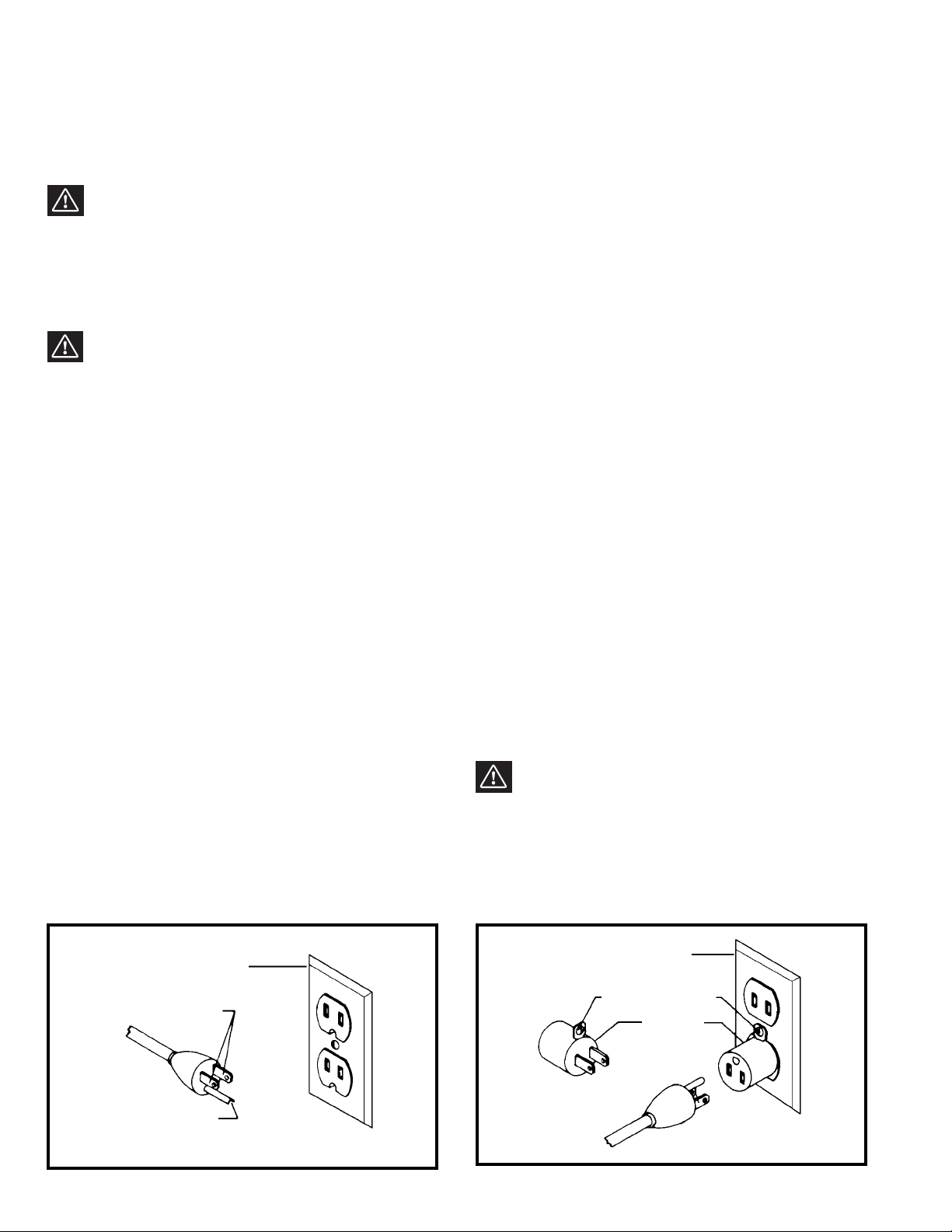
Fig. A Fig. B
GROUNDED OUTLET BOX
CURRENT
CARRYING
PRONGS
GROUNDING BLADE
IS LONGEST OF THE 3 BLADES
GROUNDED OUTLET BOX
GROUNDING
MEANS
ADAPTER
2. Grounded, cord-connected machines intended for use
on a supply circuit having a nominal rating less than 150
volts:
If the machine is intended for use on a circuit that has an
outlet that looks like the one illustrated in Fig. A, the
machine will have a grounding plug that looks like the plug
illustrated in Fig. A. A temporary adapter, which looks like
the adapter illustrated in Fig. B, may be used to connect
this plug to a matching 2-conductor receptacle as shown
in Fig. B if a properly grounded outlet is not available. The
temporary adapter should be used only until a properly
grounded outlet can be installed by a qualified electrician.
The green-colored rigid ear, lug, and the like, extending
from the adapter must be connected to a permanent
ground such as a properly grounded outlet box. Whenever
the adapter is used, it must be held in place with a metal
screw.
NOTE: In Canada, the use of a temporary adapter is not
permitted by the Canadian Electric Code.
WARNING: IN ALL CASES, MAKE CERTAIN THE
RECEPTACLE IN QUESTION IS PROPERLY
GROUNDED. IF YOU ARE NOT SURE HAVE A
QUALIFIED ELECTRICIAN CHECK THE RECEPTACLE.
1. All grounded, cord-connected machines:
In the event of a malfunction or breakdown, grounding
provides a path of least resistance for electric current to
reduce the risk of electric shock. This machine is
equipped with an electric cord having an equipmentgrounding conductor and a grounding plug. The plug must
be plugged into a matching outlet that is properly installed
and grounded in accordance with all local codes and
ordinances.
Do not modify the plug provided - if it will not fit the outlet,
have the proper outlet installed by a qualified electrician.
Improper connection of the equipment-grounding
conductor can result in risk of electric shock. The
conductor with insulation having an outer surface that is
green with or without yellow stripes is the equipmentgrounding conductor. If repair or replacement of the
electric cord or plug is necessary, do not connect the
equipment-grounding conductor to a live terminal.
Check with a qualified electrician or service personnel if
the grounding instructions are not completely
understood, or if in doubt as to whether the machine is
properly grounded.
Use only 3-wire extension cords that have 3-prong
grounding type plugs and matching 3-conductor
receptacles that accept the machine’s plug, as shown in
Fig. A.
Repair or replace damaged or worn cord immediately.
Page 5

Use proper extension cords. Make sure your extension cord is in good condition and is a 3-wire extension cord which
has a 3-prong grounding type plug and matching receptacle which will accept the machine’s plug. When using an
extension cord, be sure to use one heavy enough to carry the current of the machine. An undersized cord will cause
a drop in line voltage, resulting in loss of power and overheating. Fig. D, shows the correct gauge to use depending
on the cord length. If in doubt, use the next heavier gauge. The smaller the gauge number, the heavier the cord.
EXTENSION CORDS
OPERATING INSTRUCTIONS
FOREWORD
Delta ShopMaster Model JT160 is a 6" Variable Speed Bench Jointer with designed cutting capacity of 6" (152mm) width
and 1/8" (3mm) depth. Unit includes; 10 amp, 120 volt motor with variable speed range from 6000 to 11,000 rpm and
cutting speed range from 12,000 to 22,000 cpm, dust chute, center-mounted fence, two-knife cutterhead, cutterhead
guard and lock, wrenches and push blocks.
UNPACKING AND CLEANING
Carefully unpack the machine and all loose items from the shipping container(s). Remove the protective coating from
all unpainted surfaces. This coating may be removed with a soft cloth moistened with kerosene (do not use acetone,
gasoline or lacquer thinner for this purpose). After cleaning, cover the unpainted surfaces with a good quality household
floor paste wax.
5
Fig. D
MINIMUM GAUGE EXTENSION CORD
RECOMMENDED SIZES FOR USE WITH STATIONARY ELECTRIC MACHINES
Ampere Total Length Gauge of
Rating Volts of Cord in Feet Extension Cord
0-6 120
up to
25 18 AWG
0-6 120 25-50 16 AWG
0-6 120 50-100 16 AWG
0-6 120 100-150 14 AWG
6-10 120
up to
25 18 AWG
6-10 120 25-50 16 AWG
6-10 120 50-100 14 AWG
6-10 120 100-150 12 AWG
10-12 120
up to
25 16 AWG
10-12 120 25-50 16 AWG
10-12 120 50-100 14 AWG
10-12 120 100-150 12 AWG
12-16 120
up to
25 14 AWG
12-16 120 25-50 12 AWG
12-16 120
GREATER THAN 50 FEET NOT RECOMMENDED
Page 6
6
DEFINITIONS OF
JOINTING AND PLANING OPERATIONS
Fig. 2
Fig. 3
1. JOINTING OPERATIONS – Jointing cuts or edge
jointing are made to square an edge of a workpiece. The
workpiece is positioned on the jointer with the narrow
edge of the workpiece on the infeed table and the major
flat surface of the workpiece against the fence, as shown
in Fig. 2. The workpiece is moved from the infeed table,
across the cutterhead to the outfeed table.
2. PLANING OPERATIONS – Planing or surfacing are
identical to the jointing operation except for the position
of the workpiece. For planing, the major flat surface of
the workpiece is placed on the infeed table of the jointer
with the narrow edge of the workpiece against the fence,
as shown in Fig. 3. The workpiece is moved from the
infeed table, across the cutterhead to the outfeed table.
Use push blocks when performing planing operations
whenever possible.
Page 7

7
JOINTER PARTS
Fig. 4
1 - Jointer
2 - Fence
3 - Fence Sliding Bracket
4 - Special Nut (for assembling Fence Sliding Bracket to Fence Mounting Bracket)
5 - M8 Flat Washer (for assembling Fence Sliding Bracket to Fence Mounting Bracket)
6 - Spring Loaded Lock Handle (for assembling Fence Sliding Bracket to Fence Mounting Bracket)
7 - M6x1x16mm Button Head Screw (for assembling Fence to Fence Sliding Bracket) -(2)
8 - M6x1 Square Nut (for assembling Fence to Fence Sliding Bracket) -(2)
9 - Fence Mounting Bracket
10 - M6x1x16mm Button Head Screw (for assembling Fence Mounting Bracket to Jointer Base)- (4)
11 - Push Blocks - (2)
12 - Cutterhead Guard
13 - Cutterhead Lock
14 - M6x1x12mm Button Head Screw (for assembling Cutterhead Lock to Jointer Base)
15 - M6x1x12mm Button Head Screw (for assembling Cutterhead Guard to Jointer Base) - (2)
16 - Allen Wrenches - (2)
1
2
3
4
5
6
7
8
9
10
11
12
13
14
15
16
Page 8

8
ASSEMBLY
WARNING: FOR YOUR OWN SAFETY, DO NOT CONNECT THE MACHINE TO THE POWER SOURCE UNTIL
THE MACHINE IS COMPLETELY ASSEMBLED. DO NOT OPERATE THIS MACHINE UNTIL YOU READ AND
UNDERSTAND THE ENTIRE INSTRUCTION MANUAL
Fig. 5
Fig. 6
Fig. 7
Fig. 8
FENCE
1. Assemble the fence mounting bracket (A) Fig. 5, to
the jointer base using the four M6x1x16mm button head
screws (B) Fig. 6.
2. Assemble the fence sliding bracket (C) Fig. 7, to
mounting bracket (A) using the lockhandle (D), M8 flat
washer (E) and special nut (F) Fig. 8.
A
B
B
A
C
D
E
F
Page 9

9
Fig. 9
Fig. 10
Fig. 11
Fig. 12
3. Insert a M6x1x16mm button head screw (G) Fig. 9,
through fence tilting bracket (H) and thread a M6x1
square nut (J) onto threaded end of screw (G) as shown.
DO NOT COMPLETELY TIGHTEN SCREW (G) AT
THIS TIME. Assemble screw and square nut to opposite
end of tilting bracket in the same manner.
4. Slide groove of fence (L) Fig. 10, over square nuts (J)
as shown.
5. Position fence (L) Fig. 11, so that rounded section
(M) on bottom of fence is over cutterhead opening as
shown.
6. Tighten two screws (G) Fig. 12.
H
J
G
J
L
L
M
G
G
Page 10

10
Fig. 13
Fig. 14
Fig. 15
Fig. 16
CUTTERHEAD GUARD
1. Thread the two M6x1x12mm button head screws (A)
Fig. 13, into the two threaded holes in front side of jointer
base. DO NOT COMPLETELY TIGHTEN SCREWS (A)
AT THIS TIME.
2. Slide guard mounting bracket (B) Fig. 14, to the two
screws (A) as shown, and tighten the two screws (A).
CUTTERHEAD LOCK
Assemble cutterhead lock (A) Fig. 15, to the front side of
the jointer base, using the M6x1x12mm button head
screw (B). NOTE: THE CUTTERHEAD LOCK (A) IS TO
BE ENGAGED WITH THE CUTTERHEAD SHAFT AS
SHOWN IN FIG. 15. ONLY WHEN SETTING KNIVES.
ALL OTHER TIMES THE CUTTERHEAD LOCK (A)
SHOULD BE DISENGAGED FROM THE CUTTERHEAD,
AS SHOWN IN FIG. 16.
A
A
A
B
A
B
A
Page 11

11
FASTENING JOINTER TO SUPPORTING SURFACE
If during operation, there is any tendency for the jointer
to tip over, slide or walk on the supporting surface, the
jointer must be secured to the supporting surface with
fasteners through the four holes (A) Fig. 20, in the jointer
base, two of which are shown.
STARTING AND
STOPPING JOINTER
The on/off switch (A) Fig. 21, is located on the front of the
jointer cabinet. To turn the machine “ON,” move the
switch (A) up to the “ON” position. To turn the machine
“OFF,” move the switch (A) down to the “OFF” position.
OPERATING CONTROLS AND ADJUSTMENTS
LOCKING SWITCH IN
THE “OFF” POSITION
IMPORTANT: When the tool is not in use, the switch
should be locked in the “OFF” position to prevent
unauthorized use. Grasp the switch toggle (B) and pull
it out as shown in Fig. 22. With the switch toggle (B)
removed, the switch will not operate. However, should
the switch toggle be removed while the machine is
running, it can be turned “OFF” once, but cannot be
restarted without inserting the switch toggle (B).
Fig. 20
Fig. 21
Fig. 22
A
A
A
B
Page 12
12
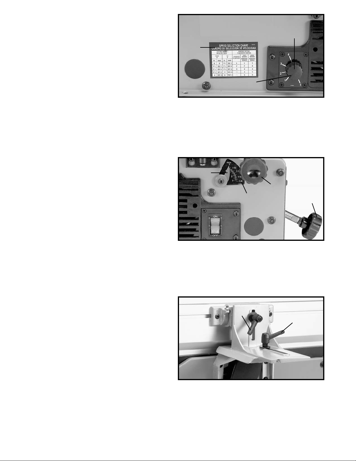
VARIABLE SPEED CONTROL
Your jointer is supplied with a variable speed control
knob (A) Fig. 23, that enables you to operate the machine
at cutterhead speeds between 6000 and 11,000 RPM.
Speed indicators of 1-2-3-4 and 5 are provided on the
speed dial as shown. When the pointer (B) is pointing to
1, the cutterhead speed will be 6000 RPM; 2 – 7250
RPM; 3 – 8800 RPM; 4 – 9750 RPM; and 5 – 11,000
RPM.
SPEED CONTROL CHART
A speed control chart (C) Fig. 23, indicates the recommended cutterhead speed setting when jointing plastics,
soft woods and hard woods from 1-1/2" to 6" wide.
DEPTH OF
CUT ADJUSTMENT
The jointer can be set to cut any depth from a very thin
shaving to 1/8" deep. A dual English/Metric scale (A)
Fig. 24, and pointer (B) are provided to indicate the depth
of cut. To adjust for depth of cut, loosen lock knob (C)
and turn adjusting knob (D) clockwise to lower and counterclockwise to raise the infeed table. After the infeed
table is at the desired setting, tighten lock knob (C).
NOTE: For best results, final positioning of the infeed
table should always be made from the bottom to the up
position.
FENCE ADJUSTMENTS
The fence can be moved across the table and can be
tilted up to 45 degrees, as follows:
1. To move the fence across the table, loosen lock lever
(A) Fig. 25, slide the fence to the desired position on the
table and tighten lever (A). NOTE: Lock lever (A) is spring
loaded and can be repositioned by pulling up on the
lever and repositioning it on the nut located underneath
the lever.
2. To tilt the fence, loosen lever (B) Fig. 25, and tilt the
fence to the desired angle. Then tighten lever (B). NOTE:
Lever (B) is spring loaded and can be repositioned by
pulling out on the lever and repositioning it on the nut
located underneath the lever.
Fig. 23
Fig. 24
Fig. 25
C
A
B
A
B
C
D
B
A
Page 13

13
Fig. 26
Fig. 27
Fig. 28
Fig. 29
3. The fence features adjustable positive stops at the
most used fence positions of 90 degrees and 45 degrees
to the right. To check and adjust the positive stops,
proceed as follows:
4. Place a square (C) Fig. 26, on the table with one end
of the square against the fence as shown. Adjust the
fence until it is exactly 90 degrees to the table.
5. Turn set screw (D) Fig. 27, until it contacts stop (E).
6. Using a square (C) Fig. 28, tilt the table to the 45
degree position and make sure the fence is 45 degrees
to the table. Adjust the fence if necessary.
7. Turn set screw (H) Fig. 29, until it contacts stop (G).
8. These positive stops enable you to rapidly position
the table to the 90 and 45 degree settings.
CAUTION: MAKE SURE THE FENCE IS IN LEVEL
CONTACT WITH THE SURFACE OF THE OUTFEED
TABLE.
C
D
E
C
H
G
Page 14
14
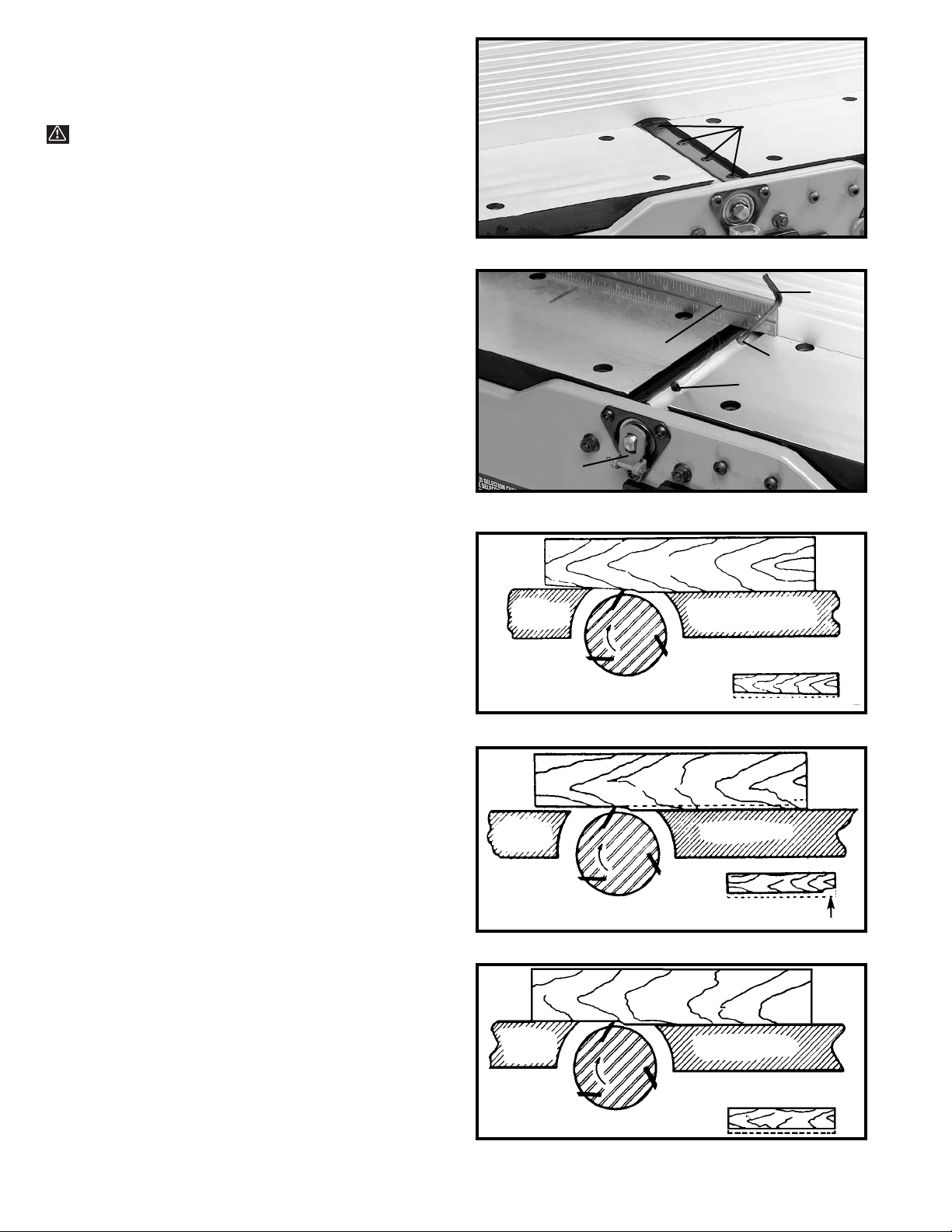
ADJUSTING KNIVES
When it becomes necessary to adjust the knives due to
replacement or wear, proceed as follows:
WARNING: THE KNIVES ARE SHARP.
1. DISCONNECT MACHINE FROM POWER SOURCE
AND REMOVE CUTTERHEAD GUARD.
2. Rotate cutterhead and loosen four screws (A) Fig.
30. NOTE: Do not overly loosen the screws (A). Loosen
one half turn or only enough so knife can slide between
locking plate and cutterhead.
3. Rotate cutterhead and engage cutterhead lock (B)
Fig. 31, on cutterhead shaft as shown. This will position
knives for proper adjustment to the outfeed table.
4. Place a straight edge (C) Fig. 31, on the outfeed
table extending out over the knife as shown. Using
wrench (D) supplied, turn screw (E) until knife just
touches straight edge. Adjust knife at near end of
cutterhead in the same manner turning screw (F).
Tighten four screws (A) Fig. 30, after adjustment is
made.
5. Adjust remaining knife in the same manner and
MAKE SURE CUTTERHEAD LOCK (B) IS DISENGAGED AFTER ADJUSTMENT IS COMPLETED AND
REPLACE CUTTERHEAD GUARD.
6. The following are examples of what will happen if
the knives are not adjusted properly.
7. If the knives are set too low, the result will be as
shown in Fig. 32, and the finished surface will be curved.
8. If the knives are set too high, the work will be
gouged at the end of the cut, as shown in Fig. 33.
9. As a final check, run a piece of work slowly over the
knives for 6 to 8 inches. The wood should rest firmly on
both tables as shown in Fig. 34, with no open spaces
under the finished cut.
Fig. 30
Fig. 31
Fig. 32
Fig. 33
Fig. 34
A
KNIVES
SET TOO LOW
OUT-FEED
TABLE
IN-FEED TABLE
CUTTER
MATERIAL
KNIVES
SET TOO HIGH
IN-FEED TABLE
OUT-FEED
TABLE
CUTTER
GOUGE
MATERIAL
IN-FEED TABLE
CUTTER
OUT-FEED
TAB LE
KNIVES AT
CORRECT HEIGHT
MATERIAL
F
E
D
C
B
Page 15

15
CHIP AND DUST CHUTE
A chip and dust chute (A) Fig. 35, is provided on the
outfeed end of the jointer base for efficient chip removal.
CAUTION: KEEP HANDS OUT OF CHIP AND DUST
CHUTE AT ALL TIMES.
Fig. 35
Fig. 36
CORD STORAGE
A cord storage bracket (A) Fig. 36, is provided on jointer
base for storage of the cord when machine is not in use.
Fig. 37
PUSH BLOCKS
A set of push blocks (A) Fig. 37, is supplied with your
jointer and should be used whenever possible to
minimize all danger to your hands. Fig. 37, illustrates
using the push blocks properly.
A
A
A
Page 16
16
OPERATION
The following directions will give the beginner a start on jointer operations. Use scrap pieces of lumber to check the
settings and to get the feel of the operations before attempting regular work.
NOTE: THE KNIVES ON THE JOINTER WILL NOT WEAR EVENLY BY FEEDING THE WOOD THROUGH THE SAME
SPOT ON THE TABLE EVERY TIME. FEED THE WOOD THROUGH THE JOINTER AT DIFFERENT SPOTS ON THE
TABLE WHEN POSSIBLE, TO HELP ELIMINATE UNEVEN WEAR OF THE KNIVES.
WARNING: ALWAYS USE CUTTERHEAD GUARD AND KEEP HANDS AWAY FROM CUTTERHEAD. USE
PUSH BLOCKS WHENEVER POSSIBLE.
Fig. 38
PLACEMENT OF HANDS
DURING FEEDING
At the start of the cut, the left hand holds the work firmly
against the infeed table and fence, while the right hand
pushes the work toward the knives. After the cut is underway, the new surface rests firmly on the outfeed table
as shown in Fig. 38. The left hand should then be moved
to the work on the outfeed table, at the same time
maintaining flat contact with the fence. The right hand
presses the work forward, and before the right hand
reaches the cutterhead it should be moved to the work
on the outfeed table. CAUTION: NEVER PASS HANDS
DIRECTLY OVER THE CUTTERHEAD.
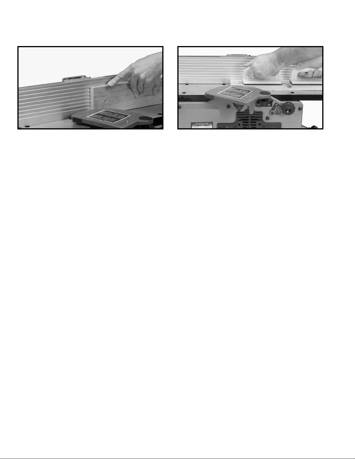
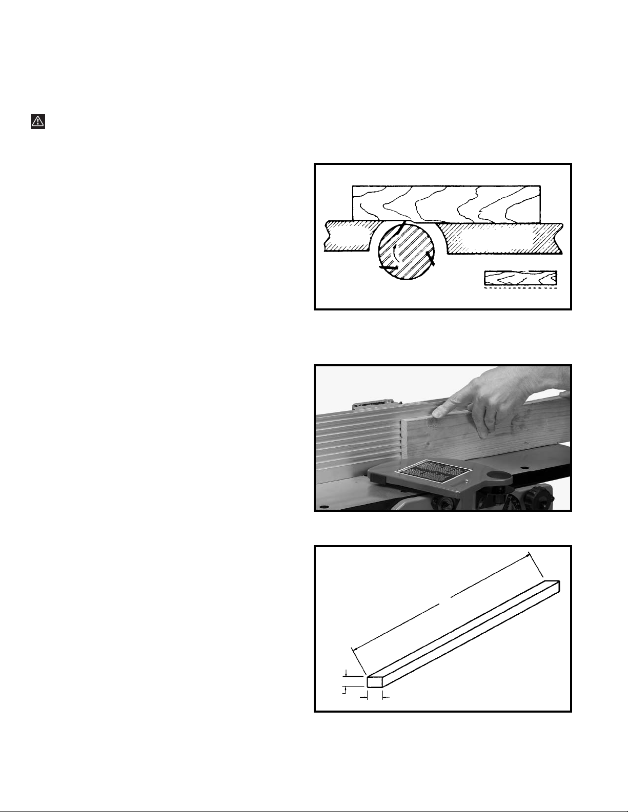
JOINTING AN EDGE
This is the most common operation for the jointer. Set
the guide fence square with the table. Depth of cut
should be the minimum required to obtain a straight
edge. Hold the best face of the piece firmly against the
fence throughout the feed as shown in Fig. 39.
DO NOT PERFORM JOINTING OPERATIONS ON
MATERIAL SHORTER THAN 10 INCHES, NARROWER
THAN 3/4 INCH, OR LESS THAN 1/2 INCH THICK
(REFER TO FIG. 39A).
Fig. 39
Fig. 39A
OUT-FEED
TABLE
IN-FEED TABLE
CUTTER
MATERIAL
3/4" MINIMUM
10" MINIMUM
MINIMUM JOINTING DIMENSIONS
1/2"
MINIMUM
Page 17

17
PLANING WARPED PIECES
If the wood to be planed is dished or warped, take light
cuts until the surface is flat. Avoid forcing such material
down against the table; excessive pressure will spring it
while passing the knives, and it will spring back and
remain curved after the cut is completed.
PLANING SHORT
OR THIN WORK
When planing short or thin pieces, always use push
blocks to minimize all danger to the hands. Fig. 40,
illustrates using the Push Blocks properly.
DO NOT PERFORM PLANING OPERATIONS ON
MATERIAL SHORTER THAN 10 INCHES, NARROWER
THAN 3/4 INCH, WIDER THAN 6 INCHES, OR LESS
THAN 1/2 INCH THICK (REFER TO FIG. 40A).
Fig. 40
Fig. 40A
Fig. 41
Fig. 42
DIRECTION OF GRAIN
Avoid feeding work into the jointer against the grain as
shown in Fig. 41. The result will be chipped and
splintered edges. Feed with the grain as shown in Fig.
42, to obtain a smooth surface.
MINIMUM AND MAXIMUM PLANING DIMENSIONS
1/2"
MINIMUM
3/4" MINIMUM
6" MAXIMUM
10" MINIMUM
IN-FEED TABLE
OUT-FEED
TABLE
CUTTER
WRONG FEED - AGAINST THE GRAIN
MATERIAL
CORRECT FEED - WITH THE GRAIN
IN-FEED TABLE
OUT-FEED
TABLE
CUTTER
MATERIAL
Page 18

18
MAINTENANCE
Fig. 43
Fig. 44
BELT REPLACEMENT
When it becomes necessary to replace the belt on your
jointer, proceed as follows:
1. DISCONNECT MACHINE FROM POWER SOURCE.
2. Remove screw (A) Fig. 43, using Allen wrench
supplied, and remove belt guard (B).
3. Loosen three screws (C) Fig. 44, to release belt
tension and remove belt (D) from pulleys.
4. Assemble new belt to the cutterhead and motor
pulleys. Press down on motor pulley (E) Fig. 44, to
tension belt and tighten three screws (C). NOTE: THERE
SHOULD BE APPROXIMATELY 1/4 INCH DEFLECTION IN THE BELT (D) AT THE CENTER SPAN OF THE
PULLEYS USING LIGHT FINGER PRESSURE. THE
BELT DOES NOT REQUIRE EXCESSIVE TENSION TO
FUNCTION PROPERLY.
5. Replace belt guard (B) Fig. 44.
B
A
B
C
C
C
D
E
Page 19

19
NOTES
Page 20

20
Two Year Limited Warranty
Delta will repair or replace, at its expense and at its option, any Delta machine, machine part, or machine accessory which
in normal use has proven to be defective in workmanship or material, provided that the customer returns the product
prepaid to a Delta factory service center or authorized service station with proof of purchase of the product within two
years and provides Delta with reasonable opportunity to verify the alleged defect by inspection. Delta may require that
electric motors be returned prepaid to a motor manufacturer’s authorized station for inspection and repair or replacement.
Delta will not be responsible for any asserted defect which has resulted from normal wear, misuse, abuse or repair or
alteration made or specifically authorized by anyone other than an authorized Delta service facility or representative. Under
no circumstances will Delta be liable for incidental or consequential damages resulting from defective products. This
warranty is Delta’s sole warranty and sets forth the customer’s exclusive remedy, with respect to defective products; all
other warranties, express or implied, whether of merchantability, fitness for purpose, or otherwise, are expressly
disclaimed by Delta.
Printed in U.S.A.
PARTS, SERVICE OR WARRANTY ASSISTANCE
All Delta Machines and accessories are manufactured to high quality standards and are serviced by a network
of Porter-Cable • Delta Factory Service Centers and Delta Authorized Service Stations. To obtain additional
information regarding your Delta quality product or to obtain parts, service, warranty assistance, or the location
of the nearest service outlet, please call 1-800-223-7278 (In Canada call 1-800-463-3582).
ACCESSORIES
A complete line of accessories is available from your Delta Supplier, Porter-Cable • Delta Factory Service Centers,
and Delta Authorized Service Stations. Please visit our Web Site www.deltamachinery.com for a catalog or
for the name of your nearest supplier.
WARNING: Since accessories other than those offered by Delta have not been tested
with this product, use of such accessories could be hazardous. For
safest operation, only
Delta recommended accessories should be used with this product.
 Loading...