

Delta Jetted Shower, Jetted Shower XO Trim, 18 Series, MultiChoice Jetted Shower, Jetted Shower XO Installation Instructions Manual
...Page 1
Single Handle Monitor®
MultiChoice® Jetted
Shower™ and Jetted
Shower XO® Trim
Installation Instructions
Owners Manual
18 Series
Write purchased model number here.
ASME A112.18.1 / CSA B125.1
ASSE 1016
®
®
U
P
C
THIS VALVE MEETS OR EXCEEDS THE
FOLLOWING STANDARDS:
ASME A112.18.1/CSA B125.1 and ASSE 1016.
CAUTION: This system/device must be set by the
installer to ensure safe, maximum temperature.
Any change in the setting may raise the discharge
temperature above the limit considered safe and
may lead to hot water burns.
NOTICE TO INSTALLER: CAUTION!–As the
installer of this valve, it is your responsibility
to properly INSTALL and ADJUST this valve
per the instructions given. This valve does
not automatically adjust for inlet temperature
changes, therefore, someone must make the
necessary Rotational Limit Stop adjustments at
the time of installation and further adjustments
may be necessary due to seasonal water
temperature change. YOU MUST inform the
owner/user of this requirement by following the
instructions. If you or the owner/user are unsure
how to properly make these adjustments, please
refer to pages 9 and 15 and if still uncertain, call
us at 1-800-345-DELTA.
After installation and adjustment, you must affix
your name, company name and the date you
adjusted the Rotational Limit Stop to the caution
label provided and apply or attach the label to
the back side of the closest cabinet door and
the warning label to the water heater. Leave
this Instruction Sheet for the owner’s/user’s
reference.
WARNING: This pressure balanced bath
valve is designed to minimize the effects
of outlet water temperature changes due to
inlet pressure changes, commonly caused by
dishwashers, washing machines, toilets and
the like. It may not provide protection from hot
water burns when there is a failure of other
temperature controlling devices elsewhere
in the plumbing system, if the rotational limit
stop is not properly set or if the hot water
temperature is changed after the settings
are made or if the water inlet changes due to
seasonal changes.
WARNING: Do not install a shut-off device on
either outlet of this valve. When this type of
device shuts off the water flow, it can defeat
the ability of the valve to balance the hot and
cold water pressures.
Table of Contents:
Warranty ............................................................................. Page 2
18 Series Installation Instructions
Separate Units ..................................................................Pages 3 - 9
Single Units ...................................................................... Pages 10 - 15
Maintenance ....................................................................... Page 16
Replacement Parts ............................................................. Pages 17 - 24
1
You May Need
1/10/12
51915 Rev. D
Page 2

All parts and finishes of the Delta® faucet are
warranted to the original consumer purchaser to
be free from defects in material & workmanship
for as long as the original consumer purchaser
owns their home. Delta Faucet Company
recommends using a professional plumber for all
installation & repair.
Delta will replace, FREE OF CHARGE, during
the warranty period, any part or finish that proves
defective in material and/or workmanship under
normal installation, use & service. Replacement
parts may be obtained by calling 1-800-345DELTA (in the U.S. and Canada) or by writing to:
In the United States:
Delta Faucet Company
Product Service
55 E. 111th Street
Indianapolis, IN 46280
In Canada:
Masco Canada Limited, Plumbing Group
350 South Edgeware Road,
St. Thomas, Ontario, Canada N5P 4L1
This warranty is extensive in that it covers
replacement of all defective parts and even
finish, but these are the only two things that
are covered. LABOR CHARGES AND/OR
DAMAGE INCURRED IN INSTALLATION,
REPAIR, OR REPLACEMENT AS WELL AS ANY
Lifetime Faucet and Finish Limited Warranty
OTHER KIND OF LOSS OR DAMAGES ARE
EXCLUDED. Proof of purchase (original sales
receipt) from the original consumer purchaser
must be made available to Delta for all warranty
claims. THIS IS THE EXCLUSIVE WARRANTY
BY DELTA FAUCET COMPANY, WHICH DOES
NOT MAKE ANY OTHER WARRANTY OF ANY
KIND, INCLUDING THE IMPLIED WARRANTY
OF MERCHANTABILITY.
This warranty excludes all industrial, commercial
& business usage, whose purchasers are
hereby extended a five year limited warranty
from the date of purchase, with all other terms
of this warranty applying except the duration of
the warranty. This warranty is applicable to Delta®
faucets manufactured after January 1, 1995.
Some states/provinces do not allow the exclusion
or limitation of incidental or consequential
damages, so the above limitation or exclusion
may not apply to you. Any damage to this faucet
as a result of misuse, abuse, or neglect, or any
use of other than genuine Delta® replacement
parts WILL VOID THE WARRANTY.
This warranty gives you specific legal rights, and
you may also have other rights which vary from
state/province to state/province. It applies only
for Delta® faucets installed in the United States of
America, Canada, and Mexico.
© 2012 Masco Corporation of Indiana
2
Delta Faucet Company
Product Service
55 E. 111th Street
Indianapolis, IN 46280
www.deltafaucet.com
Page 3
1
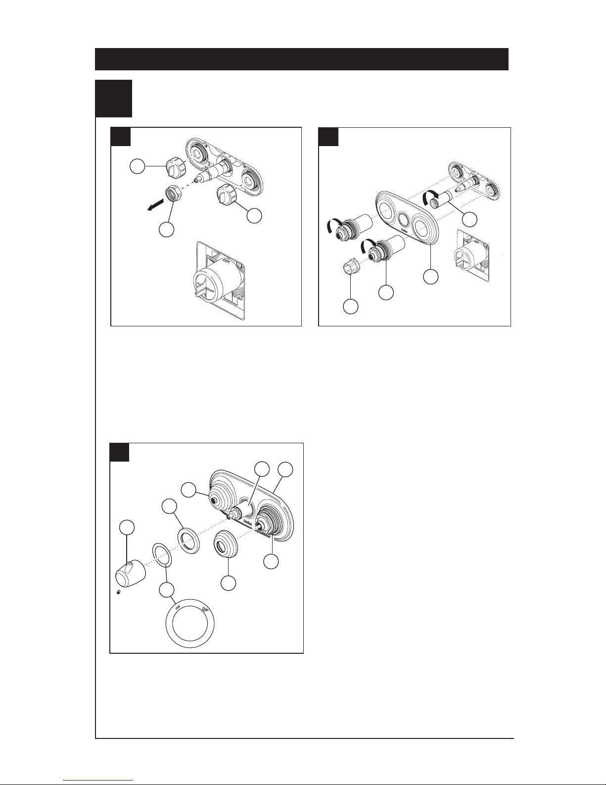
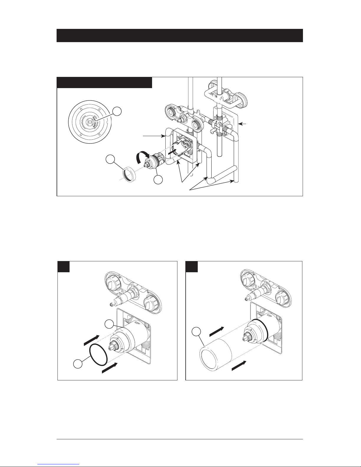
Jetted Shower™ Jet Module Trim Installation
Turn off water supplies. Unscrew test caps
(1) from the body. If this is not a thin wall
mounting, the entire plasterguard may be
removed. Remove bonnet nut (2) from
the body.
Thread sleeve (1) onto brass body, use wrench
to tighten. Place the oval escutcheon (2) over
jet body module. Thread the jet sleeve
assemblies (3) onto the jet body module. Use
the wrench (4) to tighten the sleeve assemblies.
CAUTION: DO NOT OVERTIGHTEN. TIGHTEN
UNTIL THE ESCUTCHEON IS FLAT AGAINST
THE WALL.
3
18 Series Installation - Separate Units
A.
B.
1
1
2
1
2
Assemble the off/on label (1) onto trim ring (2).
Slide trim ring onto sleeve (3) until it bottoms
out on the escutcheon (4). Install handle (5)
onto stem, tighten set screw to secure. Thread
the bonnet assemblies (6) onto the jet sleeve
assemblies (7).
1
2
3
4
5
6
6
7
C.
4
3
Page 4
1
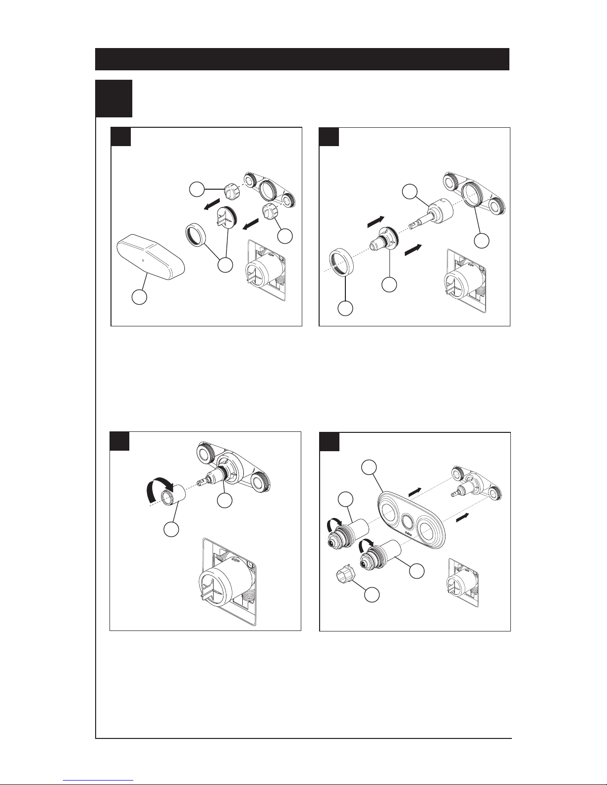
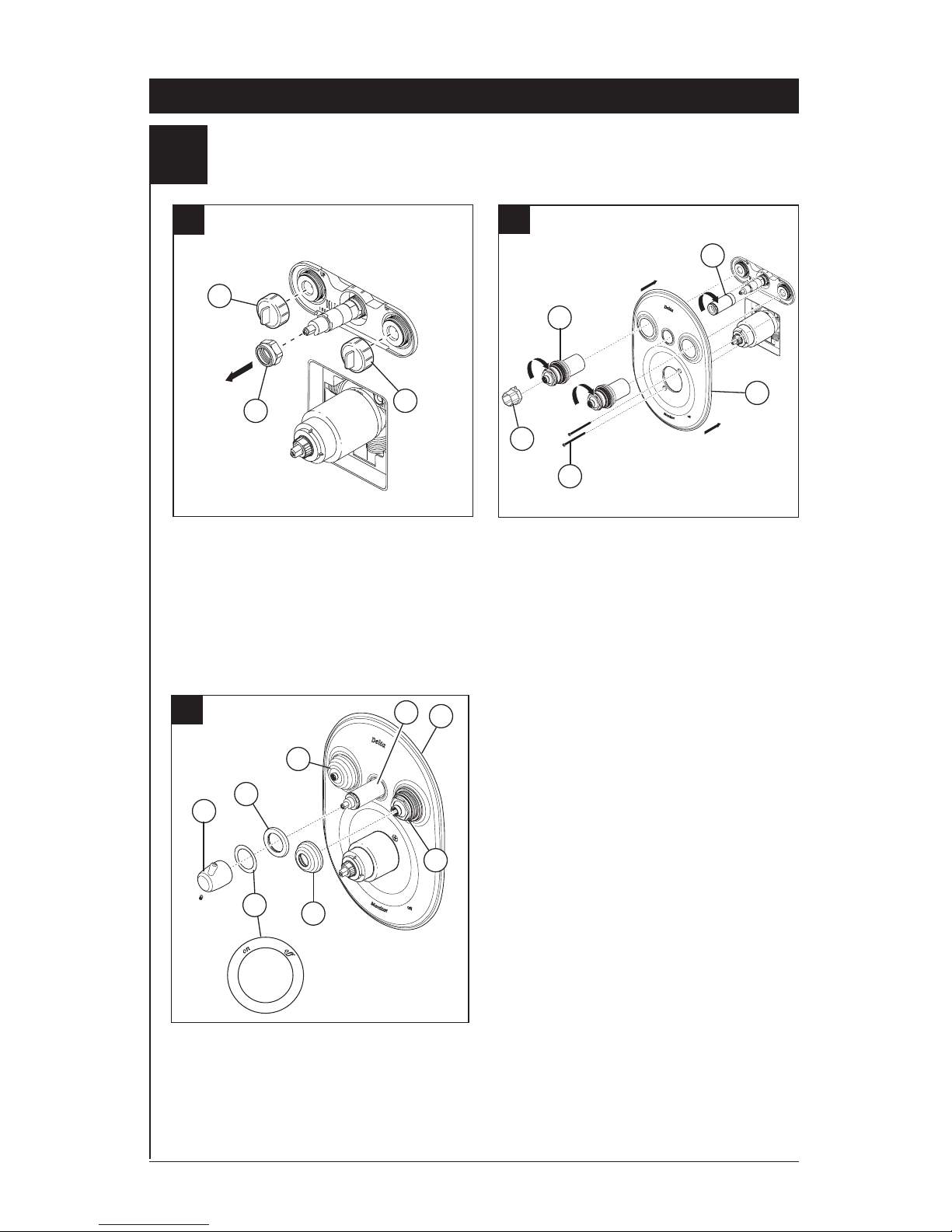
Jetted Shower XO® Jet Module Cartridge and Trim Installation
Turn off water supplies. Remove
plasterguard (1), test caps (2), bonnet nut
and test cap (3) from the body.
Install cartridge (1) into body (2). Slide
sleeve (3) over cartridge stem and onto body.
Secure with bonnet (4). Ensure bonnet is
tightened securely.
4
18 Series Installation - Separate Units
A.
B.
2
2
3
1
2
4
3
Thread trim sleeve (1) onto threaded sleeve (2).
Tighten securely with wrench.
C.
2
1
Place the oval escutcheon (1) over the jet
body module. Thread the jet sleeve
assemblies (2) onto the jet body module. Use
wrench (3) to tighten the sleeve assemblies.
CAUTION: DO NOT OVERTIGHTEN.
TIGHTEN UNTIL THE ESCUTCHEON IS
FLAT AGAINST THE WALL.
D.
3
1
2
1
2
Page 5
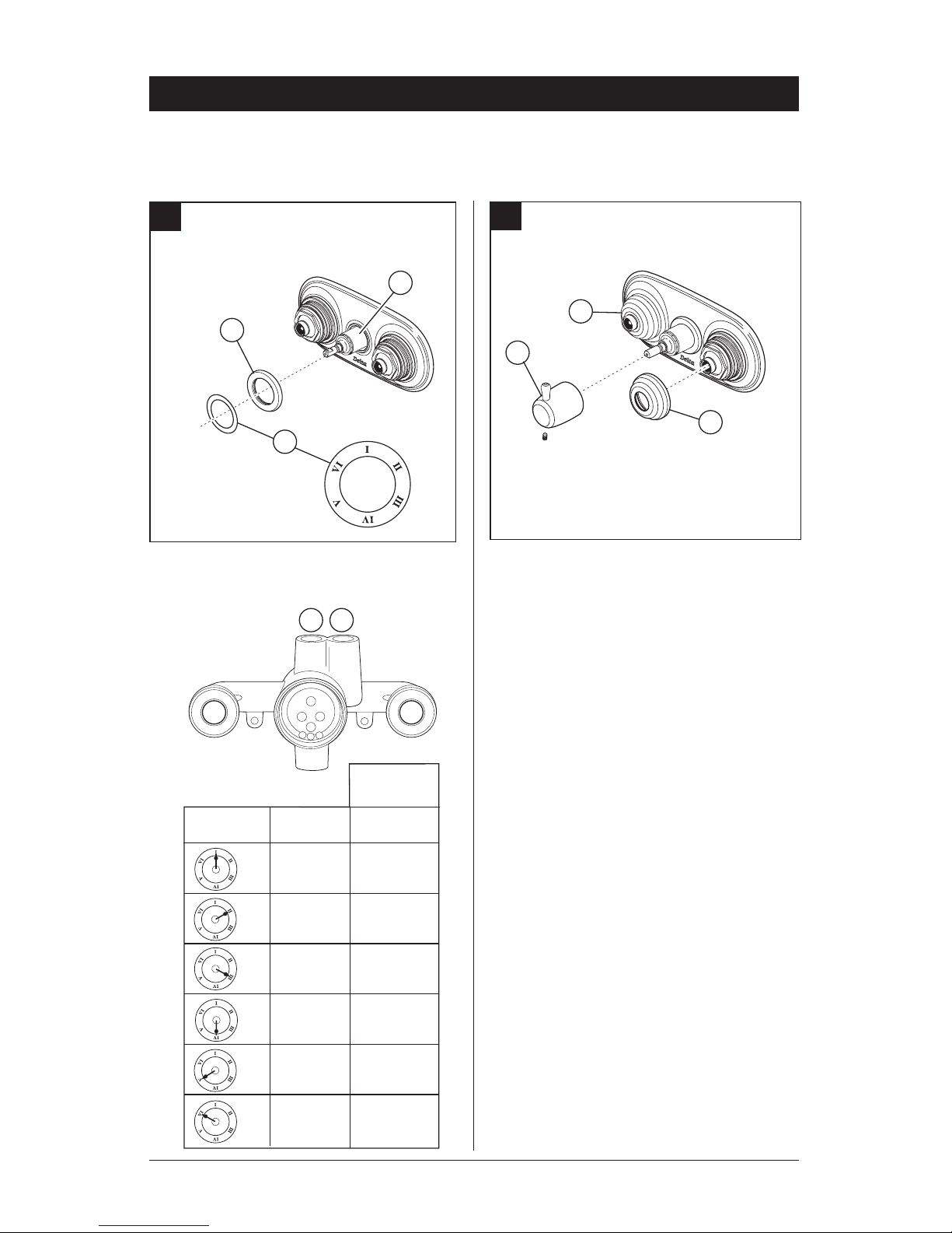
F.
Install handle (1) onto stem, tighten set screw to
secure. Thread the bonnet assemblies (2) onto
the jet sleeve assemblies.
18 Series Installation - Separate Units
1
Assemble label (1) onto trim ring (2). Slide
trim ring onto sleeve (3) until it bottoms out
on the escutcheon.
1
E.
2
5
Jetted Shower XO® Jet Module Cartridge and Trim Installation
3
2
2
1 2
33
1
Handle
Position
1 & 2
2
2 & 3
3
1 & 3
Open
Ports
VI
V
IV
III
II
I
Open
Ports
Non Shared
Cartridge
1
N/A
2
N/A
3
N/A
Page 6
18 Series Installation - Separate Units
2
Valve Cartridge Installation
A.
C.
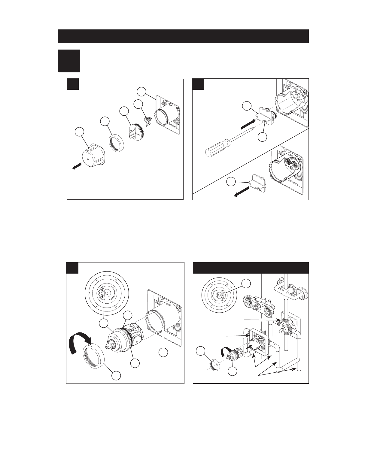
Turn off water supplies. Remove
cover (1), bonnet nut (2) and test cap (3)
from the body. If this is not a thin wall
mounting, the entire plasterguard (4) may
be removed. If screen (5) is in place, remove
before installing cartridge.
B.
Insert adapter assembly (1) into valve body.
Make sure the adapter assembly is correctly
positioned and is pressed all the way down
inside body. Secure adapter with the screw
(2) provided in the adapter assembly.
Remove the retainer (3) from the adapter.
For back to back or reverse installations
(hot on right and cold on left): Rotate cartridge
(1) so the words “HOT SIDE” (2) appear on the
right. Install the cartridge making sure that the
key is fully engaged with the slot in the brass
body (See step C). Slide bonnet nut (3) over
the cartridge and thread onto the body. Hand
tighten securely.
Back to back Installation
Rotate cartridge (1) so the words
“HOT SIDE” (2) appear on the left. Insert
cartridge assembly into valve body. Make
sure the key (3) on the cartridge is fully
engaged with the slot in the brass body (4).
Slide bonnet nut (5) over the cartridge and
thread onto the body. Hand tighten securely.
1
2
3
1
1
3
4
Reverse
Installation
Cold
Hot
1
6
5
2
3
3
4
Normal Installation
(changes not required)
2
2
5
Page 7
C.
D.
A.
B.
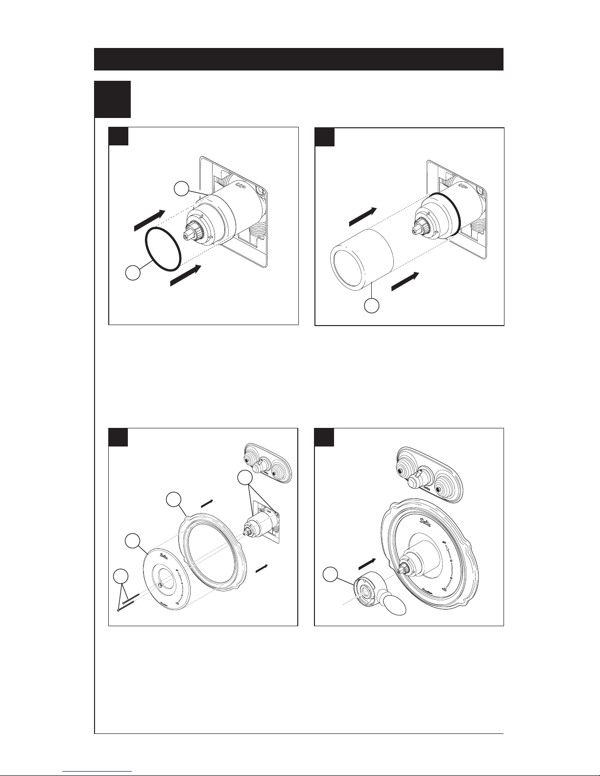
Slide O-ring (1) over cartridge and the
bonnet nut (2). The O-ring, which acts as
a spacer to steady the sleeve, should rest
behind the bonnet nut.
Slide the sleeve (1) over the cartridge, body
and O-ring. Ensure sleeve is properly positioned over the front of cartridge.
Secure the escutcheon (1) and backplate (2)
(if your model has one) to the bracket (3) with
the 2 screws provided (4). Do not overtighten
escutcheon screws.
Install volume control handle (1) with lever to
the right. DO NOT SECURE WITH SCREW.
18 Series Installation - Separate Units
3
Valve Trim Installation
1
2
1
1
2
3
4
1
7
Page 8
8
4
Showerhead and Tub Spout Installation
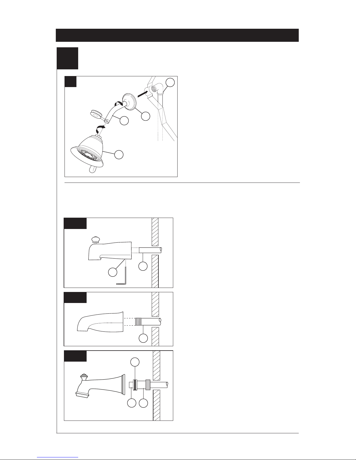
FOR SHOWERHEAD INSTALLATION:
Connect top outlet (1) to shower arm (2)
with proper fittings. To prevent damage to
finish on shower arm, insert wall end of
shower arm into shower flange (3) before
screwing arm into riser connection. Thread
showerhead (4) onto shower arm. Apply
plumber tape to pipe threads on both ends.
Do not overtighten showerhead.
A.
3
2
1
Slip-On Installation
The copper tube (1) must be 1/2” nominal
copper. Important: If it is necessary to cut the
copper tube, the end must be chamfered free
of burrs to prevent cutting or nicking O-ring
inside the spout. Slide spout over copper tube
flush with the finished tub or wall surface.
Tighten set screw (2), but do not overtighten.
4
1
FOR TUB SPOUT INSTALLATION:
Refer to the installation instructions supplied with your spout. Do not connect deck mount spouts
to in-wall valves. Do not use hand showers connected in lieu of a tub spout to a tub/shower
valve. Do not use PEX tubing for tub spout drop.
B-1
B-2
B-3
Iron Pipe Installation
Install threaded pipe nipple (1) to extend past
finished wall. Apply plumber tape to threads
on pipe nipple and screw on tub spout.
Copper Sweat Installation
Remove O-ring (1) from adapter (2). Solder
adapter to tube taking care to keep solder away
from O-ring groove. CAUTION: NO SOLDER
PERMITTED ON OUTSIDE DIAMETER OF
ADAPTER ADJACENT TO O-RING GROOVE.
Cut off tube (3) and replace O-ring on groove of
brass adapter. Thread tub/spout onto adapter,
taking care not to damage O-ring, and hand
tighten until spout is firmly against finished wall
and all slack is taken up behind wall.
2
1
1
2
3
18 Series Installation - Separate Units
Page 9

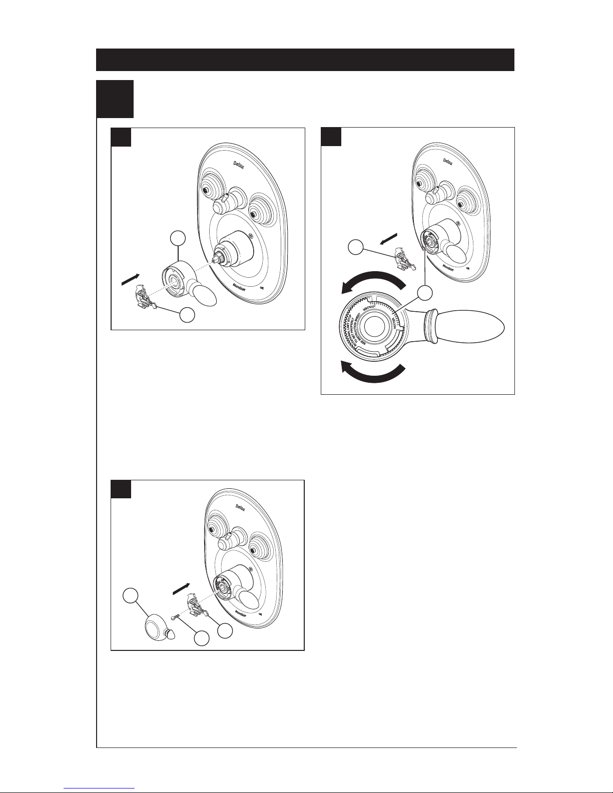
5
Installation and Adjustment of the Rotational Limit Stop
C.
A.
B.
Place the temperature control knob (1)
on volume handle and rotate to the mixed
position (if required). DO NOT SECURE WITH
SCREW. Turn on water supplies; let the water
run until both hot and cold water is as
hot/cold as possible. Place thermometer in
a plastic tumbler, and hold the tumbler in the
water stream. Record the temperature reading.
If the water temperature is above 120°F,
remove the temperature control knob (1) and
rotate the limit stop (2) clockwise one tooth for
every 4°F - 6°F (approximate) change in temperature. If water temperature is cooler than
desired, rotate the limit stop counterclockwise.
IMPORTANT: The first position of the
Rotational Limit Stop (the Limiter) is that
position that restricts the rotation of the stem
the most and is at the maximum clockwise
setting. According to industry standards, the
maximum allowable temperature of the water
exiting from the valve is 120o F. This
temperature may vary in your local area. The
Rotational Limit Stop may need to be
readjusted if the inlet water temperature
changes. For instance, during the winter, the
cold water temperature is colder than it is
during the summer which could result in
varying outlet temperatures. Typical
temperature for a comfortable bath or
shower is between 90o and 110o F.
Secure temperature control knob (1) with
screw (2) and snap control cover (3) onto
knob. NOTE: Secure screw until handle
wobble is reduced, DO NOT FULLY
TIGHTEN. Overtightening will result in
difficulty to operate temperature control knob.
Screw is self locking.
18 Series Installation - Separate Units
1
1
2
2
1
3
9
Hotter
Colder
Page 10
18 Series Installation - Single Units
1
Valve Cartridge Installation
A.
D.
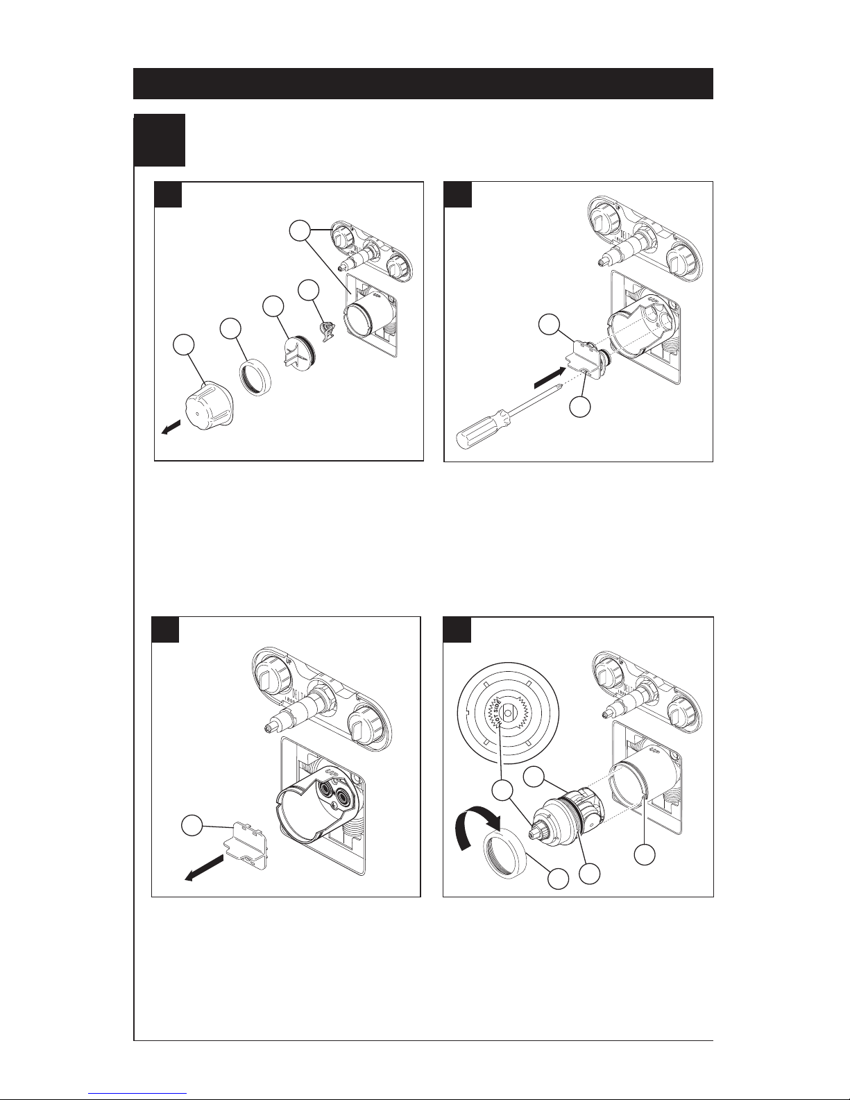
Turn off water supplies. Remove cover (1),
bonnet nut (2) and test cap (3) from the body.
If this is not a thin wall mounting, the entire
plasterguard (4) may be removed. If screen
(5) is in place, remove before
installing cartridge.
B.
Insert adapter assembly (1) into valve body.
Make sure the adapter assembly is correctly
positioned and is pressed all the way down
inside body. Secure adapter with the screw
(2) provided in the adapter assembly.
Rotate cartridge (1) so the words “HOT
SIDE” (2) appear on the left. Insert cartridge
assembly into valve body. Make sure the key
(3) on the cartridge is fully engaged with the
slot in the brass body (4). Slide bonnet nut (5)
over the cartridge and thread onto the body.
Hand tighten securely.
1
2
3
1
2
1
3
4
5
2
C.
Remove the retainer (1) from the adapter.
1
10
4
5
Page 11
E.
F.
Slide O-ring (1) over cartridge and the
bonnet nut (2). The O-ring, which acts as
a spacer to steady the sleeve, should rest
behind the bonnet nut.
Slide the sleeve (1) over the cartridge,
body and O-ring. Ensure sleeve is properly
positioned over the front of cartridge.
18 Series Installation - Single Units
1
2
1
For back to back or reverse installations
(hot on right and cold on left): Rotate
cartridge (1) so the words “HOT SIDE” (2)
appear on the right. Install the cartridge
Back to back Installation
Reverse
Installation
Cold
Hot
1
3
making sure that the key is fully engaged with
the slot in the brass body (see step D). Slide
bonnet nut (3) over the cartridge and thread
onto the body. Hand tighten securely.
Valve Cartridge Installation
11
2
Normal Installation
(changes not required)
Page 12
18 Series Installation - Single Units
12
2
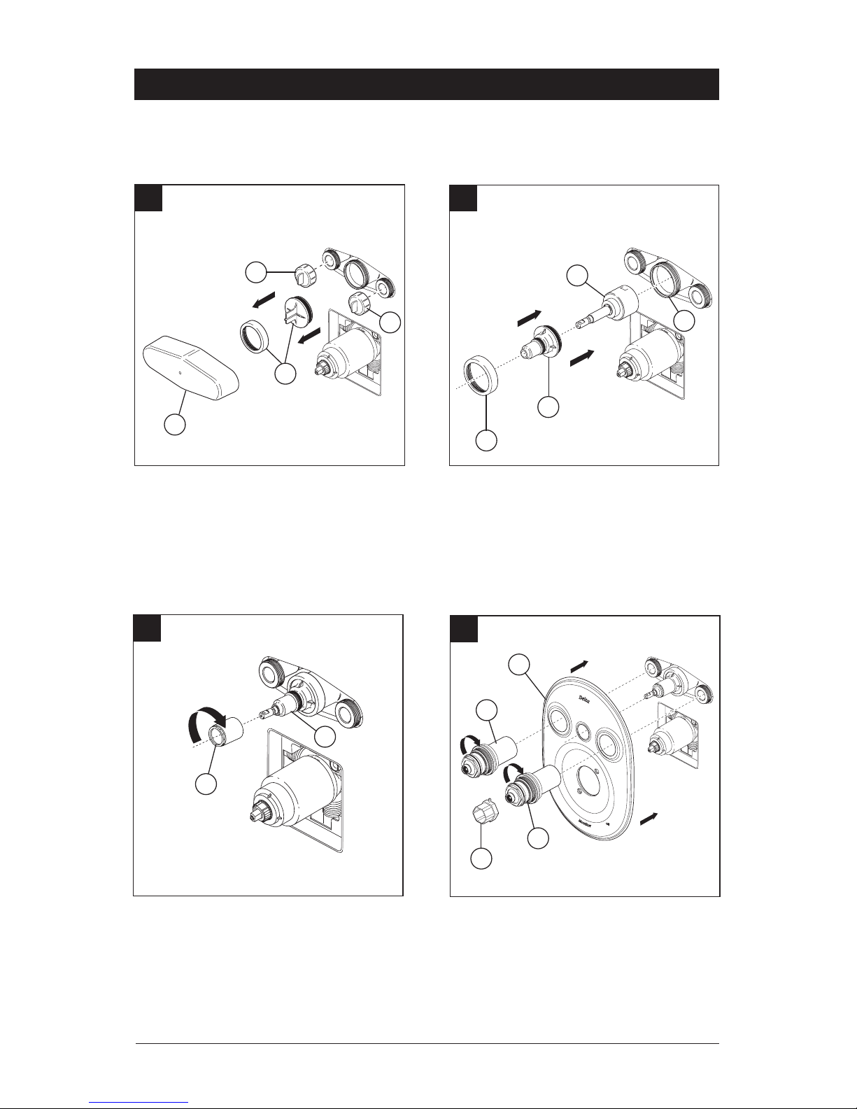
Jetted Shower™ Trim Installation
B.
Thread sleeve (1) onto brass body, use wrench
to tighten. Place escutcheon (2) over jet body
module. Install screws (3). Thread the jet sleeve
assemblies (4) onto the jet body module.
Use the wrench (5) to tighten the sleeve
assemblies. CAUTION: TIGHTEN UNTIL THE
ESCUTCHEON IS FLAT AGAINST THE WALL.
DO NOT OVER TIGHTEN.
A.
1
1
2
4
2
1
Turn off water supplies. Unscrew test caps
(1) from the body. If this is not a thin wall
mounting, the entire plasterguard may be
removed. Remove bonnet nut (2) from
the body.
5
3
Assemble the off/on label (1) onto trim ring (2).
Slide trim ring onto sleeve (3) until it bottoms
out on the escutcheon (4). Install handle (5)
onto stem, tighten set screw to secure. Thread
the bonnet assemblies (6) onto the jet sleeve
assemblies (7).
1
2
3
4
5
6
6
7
C.
Page 13
13
18 Series Installation - Single Units
Jetted Shower XO® Jet Module Cartridge and Trim Installation
Turn off water supplies. Remove
plasterguard (1), test caps (2), bonnet nut
and test cap (3) from the body.
Install cartridge (1) into body (2). Slide
sleeve (3) over cartridge stem and onto body.
Secure with bonnet (4). Ensure bonnet is
tightened securely.
A.
B.
2
2
3
1
2
4
3
Thread trim sleeve (1) onto threaded sleeve (2).
Tighten securely with wrench.
C.
2
1
Place escutcheon (1) over the jet body module.
Thread the jet sleeve assemblies (2) onto the
jet body module. Use wrench (3) to tighten the
sleeve assemblies. CAUTION: TIGHTEN UNTIL
THE ESCUTCHEON IS FLAT AGAINST THE
WALL. DO NOT OVERTIGHTEN.
D.
3
1
2
1
2
Page 14
14
3
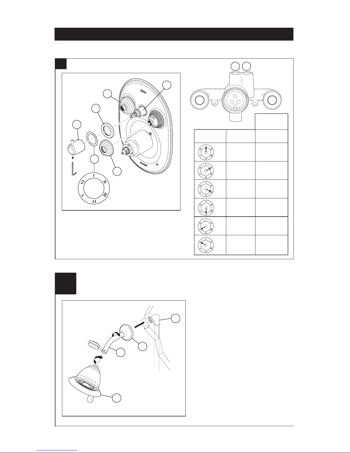
Showerhead Installation
Connect top outlet (1) to shower arm (2)
with proper fittings. Apply plumber tape
to pipe threads on both ends. To prevent
damage to finish on shower arm, insert
wall end of shower arm into shower
flange (3) before screwing arm into
riser connection. Thread showerhead (4)
onto shower arm. Do not overtighten
showerhead.
3
2
1
4
18 Series Installation - Single Units
Jetted Shower XO® Jet Module Cartridge and Trim Installation
Assemble label (1) onto trim ring (2). Slide trim
ring onto sleeve (3) until it bottoms out on the
escutcheon. Install handle (4) onto stem, tighten
set screw to secure. Thread the bonnet assemblies (5) onto the jet sleeve assemblies.
E.
2
3
1 2
33
1
4
5
5
1
Handle
Position
1 & 2
2
2 & 3
3
1 & 3
Open
Ports
VI
V
IV
III
II
I
Open
Ports
Non Shared
Cartridge
1
N/A
2
N/A
3
N/A
Page 15
4
Installation and Adjustment of the Rotational Limit Stop
C.
A.
B.
Install volume control handle (1) with lever
to the right, then turn to the on position.
DO NOT SECURE WITH SCREW. Place the
temperature control knob (2) on volume handle
and rotate to the mixed position (if required).
DO NOT SECURE WITH SCREW. Turn on
water supplies; let the water run until both hot
and cold water is as hot/cold as possible. Place
thermometer in a plastic tumbler, and hold
the tumbler in the water stream. Record the
temperature reading.
If the water temperature is above 120°F,
remove the temperature control knob (1) and
rotate the limit stop (2) clockwise one tooth for
every 4°F - 6°F (approximate) change in temperature. If water temperature is cooler than
desired, rotate the limit stop counterclockwise.
IMPORTANT: The first position of the
Rotational Limit Stop (the Limiter) is that
position that restricts the rotation of the stem
the most and is at the maximum clockwise
setting. According to industry standards, the
maximum allowable temperature of the water
exiting from the valve is 120o F. This
temperature may vary in your local area. The
Rotational Limit Stop may need to be
readjusted if the inlet water temperature
changes. For instance, during the winter, the
cold water temperature is colder than it is
during the summer which could result in
varying outlet temperatures. Typical
temperature for a comfortable bath or
shower is between 90o and 110o F.
Secure temperature control knob (1) with
screw (2) and snap control cover (3) onto
knob. NOTE: Secure screw until handle
wobble is reduced, DO NOT FULLY
TIGHTEN. Overtightening will result in
difficulty to operate temperature control knob.
Screw is self locking.
18 Series Installation - Single Units
1
1
2
2
1
3
Hotter
Colder
2
15
Page 16

Cannot receive more than a trickle of water:
Both hot and cold supply lines must be
pressurized. If only one side is pressurized, the
pressure balance system will not allow adequate
flow of water.
Volume control handle rotates 360
degrees or is not positioned correctly per
escutcheon, (sleeve is also loose). The keys
of the cartridge have not been properly placed
in the keyways in the brass body or keys on
cartridge have been sheared off due to improper
installation. BE SURE TO CORRECT THIS
SITUATION IMMEDIATELY.
Cannot receive enough hot water:
See step 3 and/or check water
heater temperature.
Faucet leaks from tub spout/showerhead:
SHUT OFF WATER SUPPLIES. Replace
Adapter Assembly –Repair Kit RP46073.
If leak persists–
SHUT OFF WATER SUPPLIES
Replace cartridge assembly–RP46463.
Unable to maintain constant water
temperature:
SHUT OFF WATER SUPPLIES. Remove
cartridge assembly, shake cartridge side to
side. Spool should rattle in sleeve. If rattle
cannot be heard, spool may be stuck. Spool
may be freed up by rapping cartridge briskly
sideways into the palm of your hand. If spool
cannot be freed, replace cartridge assembly–
RP46463.
NOTE: If the water in your area has lime, rust,
sand, or other contaminants in it, your pressure
balance valve will require periodic inspection.
The frequency of the inspection will depend on
the amount of contaminants in the water. To
inspect cartridge, remove it from the body and
shake it rigorously. If there is a rattling sound,
the unit is functional and can be reinstalled
in its previous position. If there is no rattle,
replace the cartridge with RP46463.
18 Series Maintenance
Care should be given to the cleaning of this
product. Although its finish is extremely durable, it can be damaged by harsh abrasives
or polish. To clean, simply wipe gently with a
damp cloth and blot dry with a soft towel.
Cleaning and Care
16
Page 17
1
1/10/12
51915 Rev. D
Manual de Instrucciones
para la Instalación del
Accesorio de la Regadera
a Chorro MultiChoice® de
Una Manija Monitor® Jetted
Shower™ y Jetted Shower
XO®
18 Series
Escriba aquí el número del modelo comprado.
ASME A112.18.1 / CSA B125.1
ASSE 1016
®
®
U
P
C
ESTA VÁLVULA CUMPLE O EXCEDE LAS
SIGUIENTES NORMAS: ASME A112.18 1 / CSA
B125.1 y ASSE 1016.
ADVERTENCIA: El instalador debe apostar este
sistema/divisa para garantizar temperatura máximo
y seguro. Cualquier cambio en el ajuste puede
subir la temperatura del agua de descarga sobre
el límite considerado seguro y puede resultar en
quemaduras de agua caliente.
AVISO PARA EL INSTALADOR: PRECAUCIÓN
– Como instalador de esta válvula, es su
responsabilidad de INSTALAR Y AJUSTAR
apropiadamente esta válvula como se describe
en las instrucciones, por lo tanto, debe
haber una persona para hacer los ajustes
necesarios del Tope del Límite Rotacional en el
momento que se haga la instalación y pueda
necesitar ajustes adicionales por los cambios
estacionales de la temperatura del agua. USTED
DEBE informarle al dueño/usuario sobre este
requisito siguiendo las instrucciones. Si usted
o el dueño/usuario no están seguros como
hacer estos ajustes apropiadamente, por favor
refiérase a las páginas del 9 al 15 y si todavía no
está seguro, llámenos al 1-800-345-DELTA.
Después de hacer la instalación y el ajuste,
usted puede agregarle a la etiqueta de aviso
proporcionada, su nombre, el nombre de la
compañía y la fecha cuando ajustó el Tope del
Límite Rotacional y aplicar o fijar la etiqueta al
dorso de la puerta del gabinete más cercano y la
etiqueta de aviso al calentador de agua. Deje la
Hoja de Instrucciones para referencia del dueño/
usuario.
ADVERTENCIA: Esta válvula de presión está
diseñada para minimizar los efectos de los
cambios de temperatura de agua por causa de
los cambios de presión en el agua de entrada,
comúnmente causados por lavadoras de
platos, lavadoras de ropa, inodoros, y otros
aparatos por el estilo. Puede no proporcionar
protección de quemaduras de agua caliente
cuando hay alguna falla de otros aparatos
para el control de temperatura en otro sitio
en el sistema de plomería. También no
proporcionará protección si el tope del límite
rotacional para el ajuste de la temperatura
no está apropiadamente fijo o si cambia la
temperatura del agua caliente después de
hacer los ajustes o si los cambios del agua de
entrada son por los cambios estacionales.
ADVERTENCIA: No instale un aparato de corte
o cierre en cualquiera de las tomas de esta
válvula. Cuando este tipo de aparato cierra el
flujo de agua, puede hacer fallar la habilidad
de la válvula de balancear las presiones del
agua caliente y fría.
Contenido:
Garantías ............................................................................Página 2
Instrucciones para la Instalación de la Serie 18
Unidades Separadas ...........................................................Páginas 3-9
Unidades Sencillas .............................................................Páginas 10 -15
Mantenimiento .....................................................................Página 16
Piezas de Repuesto .............................................................Páginas 17-24
Usted puede necesitar
Page 18

2
Todas las piezas y acabados de la llave Delta®
están garantizados al consumidor comprador
original, de estar libres de defectos de material
y fabricación, por el tiempo que el consumidor
comprador original sea dueño de su casa. Delta
Faucet Company recomienda que use un
plomero profesional para todas las instalaciones
y zreparaciones.
Delta reemplazará, LIBRE DE CARGO, durante
el período de garantía, cualquier pieza o
acabado que pruebe tener defectos de material
y/o fabricación bajo instalación normal, uso y
servicio. Piezas de repuesto pueden ser
obtenidas llamando al 1-800-345-DELTA (en los
Estados Unidos y Canada) o escribiendo a:
En los Estados Unidos:
Delta Faucet Company
Product Service
55 E. 111th Street
Indianapolis, IN 46280
En Canada:
Masco Canada Limited, Plumbing Group
350 South Edgeware Road,
St. Thomas, Ontario, Canada N5P 4L1
Esta garantía es extensiva en lo que cubre el
reemplazamiento de todas las piezas
defectuosas y hasta el acabado, pero éstas
son las únicas dos cosas que están cubiertas.
CARGOS DE LABOR Y/O DAÑOS INCURRIDOS
EN LA INSTALACIÓN, REPARACIÓN, O
REEMPLAZAMIENTO COMO TAMBIÉN
CUALQUIER OTRO TIPO DE PÉRDIDA O
GarantÍa Limitada De Por Vida de la Llave y su Acabado
DAÑOS ESTÁN EXCLUÍDOS. Prueba de
compra (recibo original de venta) del comprador
consumidor original debe de ser disponible a
Delta para todos los reclamos. ESTA ES LA
GARANTÍA EXCLUSIVA DE DELTA FAUCET
COMPANY, QUE NO HACE CUALQUIER
OTRA GARANTÍA DE CUALQUIER TIPO,
INCLUYENDO LA GARANTÍA IMPLÍCITA DE
COMERCIALIZACIÓN.
Esta garantía excluye todo uso industrial,
comercial y de negocio, a cuyos compradores
se les da una garantía limitada extendida de
cinco años desde la fecha de compra, con todos
los otros términos de esta garantía aplicados,
excepto el de duración de ésta. Esta garantía
es aplicable a las llaves de Delta® fabricadas
después de Enero 1, 1995.
Algunos estados/provincias no permiten la
exclusión o limitación de daños incidentales o
consecuentes, de manera que la limitación o
exclusión arriba escrita puede no aplicarle a
usted. Cualquier daño a esta llave, resultado del
mal uso, abuso, o descuido, o cualquier otro uso
de piezas de repuesto que no sean genuinas de
Delta® ANULARÁN LA GARANTÍA.
Esta garantía le da derechos legales específicos,
y usted puede, también tener otros derechos que
varían de estado/provincia a estado/provincia.
Es aplicable sólo a las llaves Delta® instaladas
en los Estados Unidos de America, Canada
y Mexico.
© 2012 Masco Corporación de Indiana
www.deltafaucet.com
Page 19

1
Instalación de Accesorios del Módulo de la Regadera a Chorro
Jetted Shower™
Cierre los suministros de agua. Destornille
las tapas de prueba (1) del cuerpo. Si no es
para instalar en pared delgada, puede quitar
el protector de yeso completo. Quite la tuerca
tapa (2) del cuerpo.
Enrosque la manga (1) en el cuerpo de
bronce. Use una llave de tuercas para apretar. Coloque la placa ovalada (2) sobre el
módulo del cuerpo del chorro. Enrosque los
ensambles de la manga del chorro (3) en el
cuerpo del módulo del chorro. Use una llave de
tuercas (4) para apretar los ensambles de la
manga. AVISO: NO APRIETE DEMASIADO.
APRIETE HASTA QUE LA PLACA QUEDE
PLANA CONTRA LA PARED.
3
Instalación de la Serie 18 - Unidades Separadas
Ensamble la etiqueta para apagar/prender ‘off/on’
(1) en el aro del accesorio (2). Deslice el aro
del accesorio (3) hasta que quede al fondo de
la chapa de cubierta (4). Instale la manija (5) en
la espiga, apriete el tornillo de ajuste para fijar.
Enrosque los ensambles del casquete (6) en los
ensambles de la manga del chorro (7).
1
2
3
4
5
6
6
7
C.
A.
B.
1
1
2
1
2
4
3
Page 20

1
Instalación de Accesorios del Módulo de la Regadera a Chorro
Jetted Shower XO®
Instalación de la Serie 18 - Unidades Separadas
4
Cierre los suministros de agua. Quite
el protector de yeso (1), las tapas de
prueba (2), el capuchón y la tapa de
prueba (3) del cuerpo.
Instale el cartucho (1) en el cuerpo (2).
Deslice la manga (3) sobre la espiga del
cartucho y en el cuerpo. Fije con el
capuchón (4). Asegure que el capuchón
esté apretado fijamente.
A.
B.
2
2
3
1
2
4
3
Enrosque la manga del accesorio (1) en la
manga enroscada (2). Apriete fijamente con
una llave de tuercas.
C.
2
1
Coloque la chapa de cubierta ovalada (1)
sobre el cuerpo del modulo del chorro de
agua. Enrosque los ensambles de la manga
del chorro (2) en el modulo del chorro de
agua. Use una llave de tuercas (3) para
apretar los ensambles de la manga.
AVISO: NO APRIETE DEMASIADO.
APRIETE HASTA QUE LA CHAPA DE
CUBIERTA QUEDE PLANA CONTRA LA
PARED.
D.
3
1
2
1
2
Page 21

F.
Instale la manija (1) en la espiga, apriete el
tornillo de ajuste para fijar. Enrosque los
ensambles del capuchón (2).
Instalación de la Serie 18 - Unidades Separadas
1
Ensamble la etiqueta (1) en el aro del
accesorio (2). Deslice el aro del accesorio
en la manga (3) hasta que quede en el
fondo de la chapa de cubierta.
1
E.
2
5
Instalación de Accesorios del Módulo de la Regadera a Chorro
Jetted Shower XO
®
3
2
2
1
2
33
1
Posición de
la manija
1 y 2
2
2 y 3
3
1 y 3
Abra los
puertos
VI
V
IV
III
II
I
Abra los
puertos
Cartucho no-
compartido
1
N/A
2
N/A
3
N/A
Page 22

Instalación de la Serie 18 - Unidades Separadas
2
Instalación del Cartucho
A.
C.
Cierre los suministros de agua. Quite la
cubierta (1), la tuerca tapa (2) y la tapa de
prueba (3). Si no es para instalar en pared
delgada, puede quitar el protector (4) de
yeso completo. Si la pantalla (5) está en lugar,
quite antes de instalar el cartucho.
B.
Introduzca el adaptador (1) en la válvula.
Asegúrese que el adaptador estén
correctamente colocados dentro de los
orificios en la base de la válvula. Fije el
adaptador con el tornillo (2) suministrado
con el adaptador. Quite el retenedor (3)
del adaptador.
En las instalaciones dorso con dorso (el agua
caliente en la derecha y la fría en la izquierda):
Gire el cartucho (1) de manera que las palabras
“HOT SIDE” (LADO CALIENTE) (2) aparezcan
en la derecha. Instale el cartucho asegurando
que la guía quede totalmente encajada en la
muesca de la pieza de latón. Deslice la tuerca
tapa (3) sobre el cartucho y enrosque en el
cuerpo de la válvula. Apriete a mano bien.
Instalación de Espalda a Espalda
Gire el cartucho (1) de manera que las
palabras ‘HOT SIDE’ (LADO CALIENTE) (2)
aparezcan en la izquierda. Introduzca el
cartucho en la válvula. Asegúrese que la
guía (3) en el cartucho esté totalmente
encajada en la muesca del cuerpo de
latón (4). Deslice la tuerca tapa (5) sobre
el cartucho y enrosque en el cuerpo de la
válvula. Apriete a mano bien.
1
2
3
1
1
3
4
Fría
Caliente
1
6
5
2
3
3
4
2
2
Instalación Normal
(No serequerá cambios)
Instalación
Invertido
5
Page 23

C.
D.
A.
B.
Deslice el aro O (1) sobre el cartucho y la
tuerca tapa (2). El aro O, el cual funciona
como un separador para estabilizar la
manga, debe quedar apoyado en la
tuerca tapa.
Deslice la manga (1) sobre el cartucho, el
cuerpo de la pieza y el aro O.
Fije la roseta con orificio (1) y la placa de
atrás (2) (si su modelo tiene una) al soporte
(3) usando los 2 tornillos suministrados (4).
No apriete demasiado los tornillos de
la roseta.
Instale la manija de control del volumen (1)
con la palanca hacia la derecha, luego gírela a
la posición abierta. NO FIJE CON TORNILLO.
Instalación de la Serie 18 - Unidades Separadas
3
Instalación Final
1
2
1
1
2
3
4
1
7
Page 24

8
Instalación de la Serie 18 - Unidades Separadas
PARA LAS INSTALACIONES DE LAS
CABEZAS DE REGADERA: Conecte
la toma de salida de agua superior (1) al
brazo de la regadera (2) con los accesorios
apropiados. Para prevenir daño al acabado
del brazo de la regadera, introduzca el
extremo que va hacia la pared del brazo
de la regadera dentro del reborde (3) antes
de atornillar el brazo en la conexión de la
tubería vertical. Aplique cinta para plomero
a los enrosques de la tubería. No apriete
demasiado la cabeza de la regadera (4).
A.
3
2
1
4
Instalación de la Cabeza de la Regadera y el Surtidor de la Bañera
Instalación deslizable
El tubo de cobre (1) debe ser de1/2" de cobre
nominal. Importante: Si es necesario cortar el
tubo de cobre, el extremo debe biselarse que
quede libre de rebabas para prevenir cortar
o mellar el aro O dentro del tubo de cobre.
Deslice el surtidor sobre el tubo de cobre al
ras con la bañera o la superficie de la pared
acabada. Apriete el tornillo de ajuste (2), pero
no apriete demasiado.
1
PARA LA INSTALACIÓN DEL SURTIDOR DE LA BAÑERA: Refiérase a las instrucciones
para la instalación suministradas con su surtidor. No conecte los surtidores para las instalaciones en las superficies horizontales en las válvulas dentro de las paredes. No use las regaderas
de mano en vez de un surtidor de bañera conectado a una válvula de bañera/regadera. No use
la tubería PEX como tubería entre la válvula y el surtidor de la bañera.
B-1
B-2
B-3
Instalación de la tubería de Hierro
IInstale una entrerrosca de tubo enroscado
de 1/2” (13 mm) (1) para extenderse por
delante de la pared acabada. Aplique cinta
para plomero a las roscas en la entrerrosca
de tubo y atornille el surtidor de la bañera.
Instalación de Soldadura de Cobre
Quite el aro O (1) del adaptador (2). Suelde el
adaptador al tubo asegurando de mantener
la soldadura lejos de las muesca del aro O.
AVISO: NO SE PERMITE SOLDAR EN EL
DIAMETRO EXTERIOR DEL ADAPTADOR
ADJUNTO A LA MUESCA DEL ARO O. Corte
el tubo (3) y coloque otra vez el aro O en la
muesca del adaptador de latón. Atornille la
bañera/surtidor al adaptador, asegurando no
dañar el aro O, y apriete a mano bien hasta que
el surtidor quede firmemente contra la pared
acabada y no quede flojo detrás de la pared.
2
1
1
2
3
4
Page 25

9
5
Instalación y Ajuste del Tope que Limita la Rotación
C.
A.
B.
Instalación y Ajuste del Tope que Limita la
Rotación Coloque la perilla para el control de
la temperatura (1) en la manija para controlar
el volumen y gire a la posición mixta (si se
requiere). NO FIJE CON TORNILLO. Abra los
suministros de agua; deje que el agua corra
hasta que ambas, el agua caliente y la fría,
estén lo más caliente/fría posible. Coloque el
termómetro en un vaso plástico, y sostenga el
vaso debajo del chorro de agua. Tome nota de
la temperatura.
Si la temperatura del agua es más de 120°F,
quite la perilla para el control de la temperatura (1) y gire el tope (2) en sentido de las
manecillas del reloj un diente por cada
4°F-6°F (aproximadamente) de cambio de
temperatura. Si la temperatura del agua es
más fría de lo deseado, gire el tope en
sentido contrario de las manecillas del reloj.
IMPORTANTE: La primera posición del tope
que limita la rotación (el pare) es aquella que
limita más la rotación de la espiga y es la
que está en la colocación máxima en sentido
contrario a las manecillas del reloj.
De acuerdo a los estándares de la industria,
la temperatura máxima permitida del agua que
sale de la válvula es 120º F. Esta temperatura
puede variar en su área. Si el agua de entrada
cambia de temperatura, se puede requerir el
reajuste del tope que limita la rotación. Por
ejemplo, durante el invierno, la temperatura
del agua fría es más fría que durante el
verano, esto puede resultar en temperaturas
variadas de agua de entrada. La temperatura
típica para un baño o ducha agradable es
entre 90° y 110° F.
Fije la perilla para el control de la temperatura
(1) con un tornillo (2) y coloque a presión la
cubierta del control (3) en la perilla. NOTA:
Fije con un tornillo hasta que se reduzca
el tambalee de la manija, NO APRIETE
TOTALMENTE. Si aprieta demasiado no
podrá operar la perilla para el control de la
temperatura fácilmente. El tornillo se cierra
automáticamente.
Instalación de la Serie 18 - Unidades Separadas
1
1
2
2
1
3
Más Caliente
Más Fría
Page 26

Instalación de la Serie 18 - Unidades Sencillas
1
Instalación del Cartucho
A.
D.
Cierre los suministros de agua. Quite la
cubierta (1), la tuerca tapa (2) y la tapa de
prueba (3). Si no es para instalar en pared
delgada, puede quitar el protector (4) de yeso
completo. Si la pantalla (5) está en lugar, quite
antes de instalar el cartucho.
B.
Introduzca el adaptador (1) en la válvula.
Asegúrese que el adaptador estén
correctamente colocados dentro de los
orificios en la base de la válvula. Fije el
adaptador con el tornillo (2) suministrado
con el adaptador.
Gire el cartucho (1) de manera que las
palabras ‘HOT SIDE’ (LADO CALIENTE)
(2) aparezcan en la izquierda. Introduzca el
cartucho en la válvula. Asegúrese que la guía
(3) en el cartucho esté totalmente encajada en
la muesca del cuerpo de latón (4). Deslice la
tuerca tapa (5) sobre el cartucho y enrosque
en el cuerpo de la válvula. Apriete a
mano bien.
1
2
3
1
2
1
3
4
5
2
C.
Quite el retenedor (1) del adaptador.
1
10
4
5
Page 27

E.
F.
Deslice el aro O (1) sobre el cartucho y la
tuerca tapa (2). El aro O, el cual funciona
como un separador para estabilizar la
manga, debe quedar apoyado en la
tuerca tapa.
Deslice la manga (1) sobre el cartucho, el
cuerpo de la pieza y el aro O.
Instalación de la Serie 18 - Unidades Sencillas
1
2
1
En las instalaciones dorso con dorso (el agua
caliente en la derecha y la fría en la izquierda):
Gire el cartucho (1) de manera que las
palabras “HOT SIDE” (LADO CALIENTE) (2)
aparezcan en la derecha. Instale el cartucho
Instalación de Espalda a Espalda
Instalación Normal (No
serequerá cambios)
Instalación
Invertido
Fría
Caliente
1
3
asegurando que la guía quede totalmente
encajada en la muesca de la pieza de latón.
Deslice la tuerca tapa (3) sobre el cartucho y
enrosque en el cuerpo de la válvula. Apriete a
mano bien.
Instalación del Cartucho
11
2
Page 28

12
2
Instalación de los Accesorios del Jetted Shower™
Instalación de la Serie 18 - Unidades Sencillas
B.
Enrosque la manga (1) en el cuerpo de bronce.
Use una llave de tuercas para apretar. Coloque
la placa ovalada (2) sobre el módulo del cuerpo
del chorro. Instale los tornillos (3). Enrosque
los ensambles de la manga del chorro (4) en
el cuerpo del módulo del chorro. Use la llave
de tuercas (5) para apretar los ensambles de
la manga. AVISO: NO APRIETE DEMASIADO.
APRIETE HASTA QUE LA PLACA QUEDE
PLANA CONTRA LA PARED.
A.
1
1
2
4
2
1
Cierre los suministros de agua. Destornille
las tapas de prueba (1) del cuerpo. Si no es
para instalar en pared delgada, puede quitar
el protector de yeso completo. Quite la tuerca
tapa (2) del cuerpo.
5
3
Ensamble la etiqueta para apagar/prender
‘off/on’(1) en el aro del accesorio (2). Deslice el
aro del accesorio (3) hasta que quede al fondo
de la chapa de cubierta (4). Instale la manija (5)
en la espiga, apriete el tornillo de ajuste para
fijar. Enrosque los ensambles del casquete (6)
en los ensambles de la manga del chorro (7).
1
2
3
4
5
6
6
7
C.
Page 29

13
Instalación de la Serie 18 - Unidades Sencillas
Instalación de Accesorios del Módulo de la Regadera a Chorro
Jetted Shower XO
®
Cierre los suministros de agua. Quite
el protector de yeso (1), las tapas de prueba
(2), el capuchón y la tapa de prueba (3) del
cuerpo.
Instale el cartucho (1) en el cuerpo (2).
Deslice la manga (3) sobre la espiga del
cartucho y en el cuerpo. Fije con el capuchón
(4). Asegure que el capuchón esté
apretado fijamente.
A.
B.
2
2
3
1
2
4
3
Enrosque la manga del accesorio (1) en la
manga enroscada (2). Apriete fijamente con una
llave de tuercas.
C.
2
1
Coloque la chapa de cubierta ovalada (1)
sobre el cuerpo del modulo del chorro de
agua. Enrosque los ensambles de la manga
del chorro (2) en el modulo del chorro de
agua. Use una llave de tuercas (3) para
apretar los ensambles de la manga.
AVISO: APRIETE HASTA QUE LA CHAPA
DE CUBIERTA QUEDE PLANA CONTRA
LA PARED. NO APRIETE DEMASIADO.
D.
3
1
2
1
2
Page 30

14
3
Instalación de la Cabeza de la Regadera
Instalación de la Serie 18 - Unidades Sencillas
Conecte la toma de salida de agua
superior (1) al brazo de la regadera (2)
con los accesorios apropiados. Para
prevenir daño al acabado del brazo
de la regadera, introduzca el extremo
que va hacia la pared del brazo de la
regadera dentro del reborde (3) antes
de atornillar el brazo en la conexión de
la tubería vertical. Aplique cinta para
plomero a los enrosques de la tubería.
No apriete demasiado la cabeza de la
regadera (4).
Instalación de Accesorios del Módulo de la Regadera a Chorro
Jetted Shower XO
®
Ensamble la etiqueta (1) en el aro del accesorio
(2). Deslice el aro del accesorio en la manga
(3) hasta que quede en el fondo de la chapa de
cubierta. Instale la manija (4) en la espiga, apriete el tornillo de ajuste para fijar. Enrosque los
ensambles del capuchón (5).
E.
2
3
1 2
33
1
4
5
5
3
2
1
4
1
Posición de
la manija
1 y 2
2
2 y 3
3
1 y 3
Abra los
puertos
VI
V
IV
III
II
I
Abra los
puertos
Cartucho no-
compartido
1
N/A
2
N/A
3
N/A
Page 31

4
Instalación y Ajuste del Tope que Limita la Rotación
C.
A.
B.
Instale la manija de control del volumen (1) con
la palanca hacia la derecha, luego gírela a la
posición abierta. NO FIJE CON TORNILLO.
Instalación y Ajuste del Tope que Limita la
Rotación Coloque la perilla para el control de la
temperatura (2) en la manija para controlar el
volumen y gire a la posición mixta (si se requiere). NO FIJE CON TORNILLO. Abra los suministros de agua; deje que el agua corra hasta que
ambas, el agua caliente y la fría, estén lo más
caliente/fría posible. Coloque el termómetro en
un vaso plástico, y sostenga el vaso debajo del
chorro de agua. Tome nota de la temperatura.
Si la temperatura del agua es más de 120°F,
quite la perilla para el control de la temperatura (1) y gire el tope (2) en sentido de las
manecillas del reloj un diente por cada
4°F-6°F (aproximadamente) de cambio de
temperatura. Si la temperatura del agua es
más fría de lo deseado, gire el tope en
sentido contrario de las manecillas del reloj.
IMPORTANTE: La primera posición del tope
que limita la rotación (el pare) es aquella que
limita más la rotación de la espiga y es la
que está en la colocación máxima en sentido
contrario a las manecillas del reloj.
De acuerdo a los estándares de la industria,
la temperatura máxima permitida del agua que
sale de la válvula es 120º F. Esta temperatura
puede variar en su área. Si el agua de entrada
cambia de temperatura, se puede requerir el
reajuste del tope que limita la rotación. Por
ejemplo, durante el invierno, la temperatura
del agua fría es más fría que durante el
verano, esto puede resultar en temperaturas
variadas de agua de entrada. La temperatura
típica para un baño o ducha agradable es
entre 90° y 110° F.
Fije la perilla para el control de la temperatura
(1) con un tornillo (2) y coloque a presión la
cubierta del control (3) en la perilla. NOTA: Fije
con un tornillo hasta que se reduzca el tambalee
de la manija, NO APRIETE TOTALMENTE. Si
aprieta demasiado no podrá operar la perilla
para el control de la temperatura fácilmente.
El tornillo se cierra automáticamente.
Instalación de la Serie 18 - Unidades Sencillas
1
1
2
2
1
3
2
Más Caliente
Más Fría
15
Page 32

No puede recibir más de un goteo de agua:
Debe de haceerse sobrepresión en ambas líneas
de suministro de agua caliente y fría. Si solamente
se le hace presión a un solo lado, el sistema de
presión balaceada no permitirá que el agua corra
adecuadamente.
La manija para el control del volúmen rota 360
grados o no está en la posición correcta de
acuerdo al espejo de popa. (El manguito tambien
está flojo). Las llaves del cartucho no han sido
apropiadamente colocadas en el chavetero en el
cuerpo de bronce o las llaves en el cartucho han
sido cortadas por causa de instalación inapropiada.
ASEGURESE DE CORREGIR ESTA SITUACION
INMEDIATAMENTE.
No puede recibir suficiente agua caliente:
Ver el paso 3 y/o examine la temperatura del
calentador de agua.
Si la llave tiene filtraciones del tubo de salida de
la bañera/regadera: CIERRE LOS SUMINISTROS
DE AGUA. Reemplace los asientos, resortes y
sellos de goma - Equipo de Reparación RP46073.
Si la filtración persiste:
CIERRE LOS SUMINISTROS DE AGUA.
Reemplace el ensamble del cartucho - RP46463
Incapaz de mantener una temperatura de
agua constante: CIERRE LOS SUMINISTRO
DE AGUA. Quite el ensamble del cartucho,
Agítelo de lado a lado. El carrete debe de sonar
dentro del manguito. Si no hay sonido, puede
ser que el carrete esté atascado. El carrrete se
puede soltar golpeá ndolo de lado a lado contra la
palma de su mano. Si el carrete no puede soltarse
reemplaze el ensamble del cartucho–RP46463
NOTA: Si el agua en su área contiene cal, moho,
arena, u otros contaminantes su válvula de
presión balanceada requerirá inspección
periódica. La frecuencia de la inspección
dependerá de la cantidad de contaminantes en
el agua. Para inspeccionar el cartucho, saque el
cartucho del cuerpo y agítelo rigurosamente. Si
hay un ruido (traqueteo) la unidad es funcional y
puede ser reinstalada en su posición anterior. Si
no hay traqueteo, reemplace el cartucho con la
pieza RP46463.
Mantenimiento de la Serie 18
Tenga cuidado al ir a limpiar este producto.
Aunque su acabado es sumamente durable,
puede ser afectado por agentes de limpieza
o para pulir abrasivos. Para limpiar su llave,
simplemente frótela con un trapo húmedo y luego
séquela con una toalla suave
Limpieza y Cuidado de su Llave
16
www.deltafaucet.com
Page 33

Instructions d’installation
des éléments de finition
du robinet Monitor® une
manette pour MultiChoice®
Jetted ShowerMC (douche
à gicleurs) et Jetted
Shower XO
®
18 Séries
Inscrivez le numéro de modèle ici.
ASME A112.18.1 / CSA B125.1
ASSE 1016
®
®
U
P
C
Ce robinet satisfait aux exigences des normes
ASME A112.18.1/CSA B125.1 et ASSE 1016 ou
les surpasse.
ATTENTION : L’installateur doit régler l’appareil
pour que la température maximale de l’eau chaude
soit sans danger. Toute modification du réglage
peut rendre l’eau trop chaude à la sortie du robinet
et celle-ci peut causer un échaudage.
AVIS À L’INSTALLATEUR : ATTENTION! –
En qualité d’installateur, vous êtes tenu
d’INSTALLER et de RÉGLER ce robinet
conformément aux instructions. Ce robinet ne
s’adapte pas automatiquement aux fluctuations
de la température de l’eau d’alimentation. Par
conséquent, il faut régler la butée limitatrice
de température au moment de l’installation et
il peut être nécessaire de faire de nouveaux
réglages par la suite en raison des fluctuations
saisonnières de la température de l’eau. VOUS
DEVEZ informer le propriétaire ou l’utilisateur
de cette exigence. En cas de doute quant à
la marche à suivre pour faire ces réglages,
veuillez consulter les pages 9 et 15. En cas de
doute, veuillez appeler au 1-800-345-DELTA.
Après avoir terminé l’installation et le réglage, vous
devez inscrire, sur l’étiquette de mise en garde
fournie, votre nom, le nom de votre entreprise et la
date à laquelle vous avez réglé la butée limitatrice
de température, puis fixer l’étiquette à l’endos de la
porte de la coiffeuse. Vous devez également fixer
l’étiquette d’avertissement au chauffe-eau. Veuillez
laisser ce feuillet d’instructions au propriétaire
ou à l’utilisateur pour qu’il puisse le consulter
au besoin.
MISE EN GARDE : Ce robinet à équilibrage de
pression pour baignoire est conçu pour limiter
les effets des fluctuations de température de
l’eau causées par les variations de la pression
d’alimentation attribuables au fonctionnement
d’un lave-vaisselle, d’une machine à laver, d’un
cabinet d’aisances ou d’un autre appareil qui
consomme de l’eau. Il peut ne pas protéger
l’utilisateur contre l’échaudage en cas de
défectuosité d’un autre dispositif de régulation
de la température, si le réglage de la butée
limitatrice de haute température est mauvais, si
la température de l’eau chaude a été modifiée
après que les réglages ont été effectués ou si la
température de l’eau d’alimentation a changé en
raison du changement de saison.
MISE EN GARDE : N’installez pas de dispositif
d’arrêt sur une sortie quelconque de ce robinet.
En interrompant l’écoulement de l’eau, ce
dispositif peut empêcher le robinet d’équilibrer
les pressions d’eau chaude et d’eau froide.
Table des matières
Garanties ............................................................................ Page 2
Instructions d’installation, série18
Appareils en deux pièces ................................................ Pages 3 - 9
Appareils monobloc...........................................................Pages 10 - 15
Maintenance ....................................................................... Page 16
Pièces de rechange ............................................................ Pages 17 - 24
1
Articles dont vous pouvez avoir besoin:
1/10/1251915 Rev. D
Page 34

2
Toutes les pièces et les finis du robinet Delta®
sont protégés contre les défectuosités de
matériau et les vices de fabrication par une
garantie qui est consentie au premier acheteur
et qui demeure valide tant que celui-ci demeure
propriétaire de sa maison. Delta recommande
de faire appel à un plombier compétent pour
l'installation et la réparation du robinet.
Pendant la période de garantie, Delta
remplacera GRATUITEMENT toute pièce
ou tout fini, présentant une défectuosité de
matériau ou un vice de fabrication pour autant
que l'appareil ait été installé, utilisé et entretenu
correctement. Pour obtenir des pièces de
rechange, veuillez communiquer par téléphone
au numéro 1-800-345-DELTA (aux États-Unis
ou au Canada) et par écrit à l'une des
adresses suivantes :
Aux États-Unis:
Delta Faucet Company
Product Service
55 E. 111th Street
Indianapolis, IN 46280
Au Canada:
Masco Canada Limited, Plumbing Group
350 South Edgeware Road,
St. Thomas, Ontario, Canada N5P 4L1
La présente garantie s'applique au remplacement
de toutes les pièces défectueuses, y compris
le fini, et elle ne couvre que ces éléments. LES
FRAIS DE MAIN-D'OEUVRE ET (OU) LES
DOMMAGES PROVOQUÉS AU COURS DE
L'INSTALLATION, DE LA RÉPARATION OU DU
REMPLACEMENT D'UN ÉLÉMENT AINSI QUE
LES PERTES OU DOMMAGES DE TOUTE
Garantie à vie limitée des robinets et de leurs finis
AUTRE NATURE NE SONT PAS COUVERTS
PAR LA GARANTIE. Toute réclamation en vertu
de la présente garantie doit être adressée à
Delta, accompagnée de la preuve d'achat
(original de la facture) du premier acheteur.
CETTE GARANTIE EST LA SEULE OFFERTE
PAR DELTA FAUCET COMPANY OU DELTA
FAUCET CANADA, SELON LE CAS. ELLE
EXCLUT TOUTE AUTRE GARANTIE, Y
COMPRIS LA GARANTIE IMPLICITE DE
QUALITÉ MARCHANDE.
Les robinets installés dans un établissement
industriel ou commercial ou dans une place
d'affaires sont protégés par une grantie étandue
de cinq ans qui prend effet à compter de la date
d'achat. Toutes les autres conditions de la
garantie de cinq ans sont identiques à celle de la
présente garantie. La présente garantie
s'applique à tous les robinets Delta® fabriqués
après le 1er janvier 1995.
Dans les États ou les provinces où il est interdit
d'exclure ou de limiter les responsabilités à
l'égard des dommages indirects ou fortuits, les
exclusions et les limites susmentionnées ne
s'appliquent pas. Les dommages résultant d'une
mauvaise utilisation, d'une utilisation abusive de
la négligence ou de l'utilisation de pièces autres
que des pièces d'origine Delta® RENDENT LA
GARANTIE NULLE ET SANS EFFET.
La présente garantie vous donne des droits
précis qui peuvent varier selon votre lieu de
résidence. Elle ne s'applique qu'aux robinets
Delta® installés aux États-Unis, au Canada et
au Mexique.
© 2012 Division de Masco Indiana
Page 35

1
Installation des éléments de finition du module de gicleurs
Jetted Shower
MC
Interrompez l’alimentation en eau.
Desserrez les capuchons d’essai (1) et
retirez-les du corps. Si vous n’installez pas
l’appareil dans une paroi mince, vous pouvez
retirer le protecteur complètement. Retirez
l’écrou à portée sphérique (2) du corps.
Vissez le manchon (1) sur le corps en laiton.
Serrez-le avec la clé. Placez la plaque de finition ovale (2) sur le module de gicleurs. Vissez
les manchons de gicleur (3) sur le module
de gicleurs. Utilisez la clé (4) pour serrer les
manchons. ATTENTION : PRENEZ GARDE
DE TROP SERRER. SERREZ JUSQU’À CE
QUE LA PLAQUE DE FINITION SOIT BIEN
APPUYÉE CONTRE LE MUR.
3
Installation – Série 18 - Appareils en deux pièces
Placez l’étiquette off/on (1) sur l’anneau de finition (2). Faites glisser l’anneau de finition sur
le manchon (3) jusqu’à ce qu’il s’appuie sur la
plaque de finition (4). Montez la manette (5)
sur la tige. Fixez-la en serrant la vis de calage.
Montez les enjoliveurs (6) sur les manchons
de giclage (7).
1
2
3
4
5
6
6
7
C.
A.
B.
1
1
2
1
2
4
3
Page 36

1
Installation des éléments de finition du module de gicleurs
Jetted Shower XO®
Installation – Série 18 - Appareils en deux pièces
4
Interrompez l’alimentation en eau.
Retirez le protecteur (1), les capuchons
d’essai (2), l’écrou du chapeau et le
capuchon d’essai (3) du corps.
Montez la cartouche (1) dans le corps (2).
Faites glisser le manchon (3) sur la tige de
la cartouche et sur le corps, puis fixez-le à
l’aide du chapeau (4). Serrez le chapeau
solidement.
A.
B.
2
2
3
1
2
4
3
Vissez le manchon de finition (1) sur le
manchon fileté (2). Serrez solidement avec
la clé.
C.
2
1
Placez la plaque de finition ovale (1) sur le
module de gicleurs. Vissez les manchons de
gicleur (2) sur le module de gicleurs. Utilisez
la clé (3) pour serrer les manchons.
ATTENTION – SERREZ JUSQU’À CE QUE
LA PLAQUE DE FINITION SOIT BIEN
APPUYÉE CONTRE LE MUR. PRENEZ
GARDE DE TROP SERRER.
D.
3
1
2
1
2
Page 37

Installation – Série 18 - Appareils en deux pièces
Installation des éléments de finition du module de gicleurs
Jetted Shower XO®
F.
Placez la manette (1) sur la tige et serrez la vis
de calage. Vissez les chapeaux (2) sur les
manchons de gicleur.
1
Placez l’étiquette (1) sur l’anneau de finition
(2). Faites glisser l’anneau de finition sur le
manchon (3) jusqu’à ce qu’il s’appuie sur la
plaque de finition.
1
E.
2
5
3
2
2
1 2
3
3
1
Position De
Poignée
1 et 2
2
2 et 3
3
1 et 3
Ouvrez
Les Ports
VI
V
IV
III
II
I
Ouvrez
Les Ports
Cartouche
non partagée
1
Sans
objet
2
3
Sans
objet
Sans
objet
Page 38

Installation – Série 18 - Appareils en deux pièces
2
Installation de la cartouche.
A.
C.
Interrompez l’arrivée d’eau. Enlevez le
couvercle (1), l’écrou à portée sphérique (2)
et le capuchon d’essai (3) du corps.
Si vous n’installez pas l’appareil dans une
paroi mince, vous pouvez retirer le protecteur
(4) complètement. Si l’écran (5) est en place,
enlevez avant d’installer la cartouche.
B.
Introduisez l’adaptateur (1) dans le corps
de la soupape. Assurez-vous que les
l’adaptateur sont positionnés correctement
dans les trous à la base du corps. Fixez
l’adaptateur avec la vis (2) se trouvant dans
celui-ci. Retirez la pièce de retenue (3)
de l’adaptateur.
Dans le cas d’une installation dos à dos ou
inversée (eau chaude à droite et eau froide à
gauche) : Tournez la cartouche (1) de sorte que
la mention « HOT SIDE »(2) se trouve du côté
droit. Installez la cartouche en vous assurant
que l’ergot est parfaitement engagé dans la
rainure du corps en laiton. Faites glisser l’écrou à
portée sphérique (3) sur la cartouche et vissez-le
sur le corps. Serrez à la main fermement.
Installation dos à dos
Tournez la cartouche (1) de sorte que la mention « HOT SIDE » (2) se trouve du côté gauche.
Introduisez la cartouche dans le corps de la
soupape. Assurez-vous que l’ergot (3) sur la
cartouche est parfaitement engagé dans la rainure du corps en laiton (4). Faites glisser l’écrou à
portée sphérique (5) sur la cartouche et vissezle sur le corps. Serrez à la main fermement.
1
2
3
1
1
3
4
Installation
Inversée
Eau Froides
Eau Chaude
1
6
5
2
3
3
4
Installation normale
(Non modifiée)
2
2
5
Page 39

C.
D.
A.
B.
Faites glisser le joint torique (1) sur la
cartouche et l’écrou à portée sphérique
(2). Le joint sert de pièce d’espacement
et il stabilise le manchon; il doit se trouver
derrière l’écrou à portée sphérique.
Faites glisser le manchon (1) sur la
cartouche, le corps et le joint torique.
Fixez la rosace (1) et la plaque arrière (2)
(si le modèle que vous installez en
comporte une) sur le support (3) à l’aide
des 2 vis fournies (4). Prenez garde de
serrer les vis de la rosace excessivement.
Installez la manette de réglage de débit (1)
de manière qu’elle pointe vers la droite, puis
placez-la en position d’ouverture. NE LA
FIXEZ PAS AVEC LA VIS.
Installation – Série 18 - Appareils en deux pièces
3
Installation des pièces de finition
1
2
1
1
2
3
4
1
7
Page 40

8
Installation – Série 18 - Appareils en deux pièces
4
Installation de la pomme de douche et du bec de baignoire
INSTALLATION DE LA POMME DE
DOUCHE : Raccordez la sortie supérieure
(1) au tuyau d’alimentation de la pomme de
douche (2) à l’aide des raccords appropriés.
Pour éviter d’abîmer le fini du tuyau de la
pomme de douche, introduisez le côté « mur
» de celui-ci dans la collerette (3) avant de
le visser dans le raccord du tuyau vertical.
Appliquez du ruban de plomberie sur les
filets. Vissez la pomme de douche (4) sur le
tuyau. Appliquez du ruban de plomberie sur
les filets. Prenez garde de serrer la pomme
de douche excessivement.
A.
3
2
1
4
Installation d’un bec coulissant
Le tube de cuivre (1) doit avoir un diamètre
nominal de1/2 po. Important : Si vous devez
couper le tube de cuivre, chanfreinez son
extrémité de sorte qu’elle ne risque pas
d’endommager le joint torique à l’intérieur du
bec. Faites glisser le bec sur le tube de cuivre
de sorte qu’il s’appuie contre la surface finie
de la baignoire ou du mur. Serrez la vis de
calage (3), mais prenez garde de la serrer
excessivement.
1
INSTALLATION DU BEC DE BAIGNOIRE : Consultez les instructions d’installation fournies avec
le bec. Ne raccordez pas à une soupape murale à un bec conçu pour être monté sur une plage. Ne
raccordez pas une douche à main à la sortie d’un robinet de baignoire-douche prévue pour un bec
de baignoire.
N’utilisez pas de tube PEX pour raccorder le bec.
B-1
B-2
B-3
Installation à l’aide d’un tuyau de fer
Installez le manchon fileté (1) 1/2 po (13 mm)
de manière que sa saillie par rapport à la
surface finie du mur. Appliquez du ruban de
plomberie sur les filets du manchon et fixez
celui-ci au bec de baignoire en vissant.
Installation à l’aide d’un tuyau de cuivre brasé
Retirez le joint torique (1) de l’adaptateur (2).
Brasez l’adaptateur au tube en prenant garde
d’échapper du métal d’apport dans la rainure
pour le joint torique. ATTENTION : IL NE
DOIT PAS Y AVOIR DE MÉTAL D’APPORT
SUR LA CIRCONFÉRENCE EXTÉRIEURE
DE L’ADAPTATEUR PRÈS DE LA RAINURE
POUR LE JOINT TORIQUE. Coupez le tube
(3) et remettez le joint torique en place dans
la raInure de l’adaptateur en laiton. Vissez le
bec de baignoire sur l’adaptateur et prenant
garde d’abîmer le joint torique. Serrez le bec
à la main jusqu’à ce qu’il s’appuie solidement
contre la surface finie de la paroi et qu’il
n’y ait plus de jeu derrière le mur.
2
1
1
2
3
Page 41

Installation – Série 18 - Appareils en deux pièces
9
5
Installation et réglage de la butée anti-échaudage
C.
A.
B.
Placez le bouton de réglage de température (1)
sur la manette de réglage de débit et tournezle jusqu’à la position de mélange (au besoin).
NE LE FIXEZ PAS AVEC LA VIS. Rétablissez
l’alimentation en eau. Laissez couler l’eau
jusqu’à ce que l’eau froide soit aussi froide que
possible et que l’eau chaude soit aussi chaude
que possible. Mettez un thermomètre dans un
gobelet en plastique, puis placez le gobelet
sous le jet d’eau et attendez un peu. Notez la
température de l’eau.
Si la température de l’eau sur le thermomètre
est supérieure à 120 °F, retirez le bouton
de réglage de température (1) et tournez
la butée anti-échaudage (2) dans le
sens horaire d’un cran par tranche de
température d’environ 4 à 6 °F. Si l’eau
n’est plus assez chaude, tournez la butée
anti-échaudage dans le sens antihoraire.
IMPORTANT: La première position de la
butée anti-échaudage est celle qui limite le
plus la rotation de la tige; elle se trouve à
l’extrémité de la plage dans le sens horaire.
Selon les normes de l’industrie, la température
maximale de l’eau à la sortie de la soupape
ne doit pas dépasser 120 ° F. La température
peut varier selon la région. Le réglage de la
butée anti-échaudage peut être modifié si la
température de l’eau d’alimentation a changé.
À titre d’exemple, la température de l’eau
froide est plus basse en hiver, ce qui influence
la température de l’eau à la sortie de la
soupape. La température idéale de l’eau pour
un bain ou une douche se situe entre
90 et 110 ° F.
Fixez le bouton de réglage de température (1)
avec la vis (2) et, en poussant fermement sur
celui-ci, calez le couvercle (3) sur le bouton.
NOTE : Serrez la vis jusqu’à ce que la manette
cesse d’osciller. NE LA SERREZ PAS À FOND.
Si vous la serrez excessivement, le bouton de
réglage de température sera difficile à tourner.
La vis est du type à autofreinage.
1
1
2
2
1
3
Plus Chaud
Plus Froid
Page 42

Installation – Série 18 - Appareils monobloc
1
Installation de la cartouche.
A.
D.
Interrompez l’arrivée d’eau. Enlevez le
couvercle (1), l’écrou à portée sphérique (2)
et le capuchon d’essai (3) du corps.
Si vous n’installez pas l’appareil dans une
paroi mince, vous pouvez retirer le protecteur
(4) complètement. Si l’écran (5) est en place,
enlevez avant d’installer la cartouche.
B.
Introduisez l’adaptateur (1) dans le corps
de la soupape. Assurez-vous que les
l’adaptateur sont positionnés correctement
dans les trous à la base du corps. Fixez
l’adaptateur avec la vis (2) se trouvant dans
celui-ci.
Tournez la cartouche (1) de sorte que la mention « HOT SIDE » (2) se trouve du côté gauche.
Introduisez la cartouche dans le corps de la
soupape. Assurez-vous que l’ergot (3) sur la
cartouche est parfaitement engagé dans la rainure du corps en laiton (4). Faites glisser l’écrou à
portée sphérique (5) sur la cartouche et vissezle sur le corps. Serrez à la main fermement.
1
2
3
1
2
1
3
4
5
2
C.
Retirez la pièce de retenue (1) de l’adaptateur.
1
10
4
5
Page 43

E.
F.
Faites glisser le joint torique (1) sur la
cartouche et l’écrou à portée sphérique (2).
Le joint sert de pièce d’espacement et il stabilise le manchon; il doit se trouver derrière
l’écrou à portée sphérique.
Faites glisser le manchon (1) sur la
cartouche, le corps et le joint torique.
Installation – Série 18 - Appareils monobloc
1
2
1
Dans le cas d’une installation dos à dos ou
inversée (eau chaude à droite et eau froide à
gauche) : Tournez la cartouche (1) de sorte
que la mention « HOT SIDE »(2) se trouve
du côté droit. Installez la cartouche en vous
Installation dos à dos
1
3
assurant que l’ergot est parfaitement engagé
dans la rainure du corps en laiton. Faites glisser
l’écrou à portée sphérique (3) sur la cartouche
et vissez-le sur le corps. Serrez à la main
fermement.
Installation de la cartouche.
11
2
Installation
Inversée
Eau Froides
Eau Chaude
Installation normale
(Non modifiée)
Page 44

12
2
Installation des éléments de finition Jetted Shower
MC
Installation – Série 18 - Appareils monobloc
B.
Vissez le manchon (1) sur le corps en laiton.
Serrez-le avec la clé. Placez la plaque de finition (2) sur le module de gicleurs. Montez les
vis (3). Vissez les manchons de gicleur (4) sur
le module de gicleurs. Utilisez la clé (5) pour
serrer les manchons. ATTENTION : PRENEZ
GARDE DE TROP SERRER. SERREZ
JUSQU’À CE QUE LA PLAQUE DE FINITION
SOIT BIEN APPUYÉE CONTRE LE MUR.
A.
1
1
2
4
2
1
Interrompez l’alimentation en eau.
Desserrez les capuchons d’essai (1) et
retirez-les du corps. Si vous n’installez pas
l’appareil dans une paroi mince, vous pouvez
retirer le protecteur complètement. Retirez
l’écrou à portée sphérique (2) du corps.
5
3
Placez l’étiquette off/on (1) sur l’anneau de finition (2). Faites glisser l’anneau de finition sur
le manchon (3) jusqu’à ce qu’il s’appuie sur la
plaque de finition (4). Montez la manette (5)
sur la tige. Fixez-la en serrant la vis de calage.
Montez les enjoliveurs (6) sur les manchons de
giclage (7).
1
2
3
4
5
6
6
7
C.
Page 45

13
Installation – Série 18 - Appareils monobloc
Installation des éléments de finition du module de gicleurs Jetted Shower XO
®
Interrompez l’alimentation en eau. Retirez
le protecteur (1), les capuchons d’essai (2),
l’écrou du chapeau et le capuchon d’essai
(3) du corps.
Montez la cartouche (1) dans le corps (2).
Faites glisser le manchon (3) sur la tige de la
cartouche et sur le corps, puis fixez-le à l’aide
du chapeau (4). Serrez le chapeau solidement.
A.
B.
2
2
3
1
2
4
3
Vissez le manchon de finition (1) sur le manchon
fileté (2). Serrez solidement avec la clé.
C.
2
1
Placez la plaque de finition ovale (1) sur le
module de gicleurs. Vissez les manchons de
gicleur (2) sur le module de gicleurs. Utilisez
la clé (3) pour serrer les manchons.
ATTENTION – SERREZ JUSQU’À CE QUE
LA PLAQUE DE FINITION SOIT BIEN
APPUYÉE CONTRE LE MUR. PRENEZ
GARDE DE TROP SERRER.
D.
3
1
2
1
2
Page 46

3
Installation de la pomme de douche
Raccordez la sortie supérieure (1)
au tuyau d’alimentation de la pomme
de douche (2) à l’aide des raccords
appropriés. Pour éviter d’abîmer le fini du
tuyau de la pomme de douche, introduisez
le côté « mur » de celui-ci dans la
collerette (3) avant de le visser dans le
raccord du tuyau vertical. Appliquez du
ruban de plomberie sur les filets. Vissez
la pomme de douche (4) sur le tuyau.
Appliquez du ruban de plomberie sur les
filets. Prenez garde de serrer la pomme
de douche excessivement.
3
2
1
4
14
Installation – Série 18 - Appareils monobloc
Installation des éléments de finition du module de gicleurs Jetted Shower XO
®
Placez l’étiquette (1) sur l’anneau de finition (2).
Faites glisser l’anneau de finition sur le manchon
(3) jusqu’à ce qu’il s’appuie sur la plaque de finition. Placez la manette (4) sur la tige et serrez
la vis de calage. Vissez les chapeaux (5) sur les
manchons de gicleur.
E.
2
3
1 2
33
1
4
5
5
1
Position De
Poignée
1 et 2
2
2 et 3
3
1 et 3
Ouvrez
Les Ports
VI
V
IV
III
II
I
Ouvrez
Les Ports
Cartouche
non partagée
1
Sans
objet
2
3
Sans
objet
Sans
objet
Page 47

4
Installation et réglage de la butée anti-échaudage
C.
A.
B.
Placez le bouton de réglage de température (1)
sur la manette de réglage de débit et tournezle jusqu’à la position de mélange (au besoin).
NE LE FIXEZ PAS AVEC LA VIS. Rétablissez
l’alimentation en eau. Laissez couler l’eau
jusqu’à ce que l’eau froide soit aussi froide que
possible et que l’eau chaude soit aussi chaude
que possible. Mettez un thermomètre dans un
gobelet en plastique, puis placez le gobelet
sous le jet d’eau et attendez un peu. Notez la
température de l’eau.
Si la température de l’eau sur le thermomètre
est supérieure à 120 °F, retirez le bouton
de réglage de température (1) et tournez
la butée anti-échaudage (2) dans le
sens horaire d’un cran par tranche de
température d’environ 4 à 6 °F. Si l’eau
n’est plus assez chaude, tournez la butée
anti-échaudage dans le sens antihoraire.
IMPORTANT: La première position de la
butée anti-échaudage est celle qui limite le
plus la rotation de la tige; elle se trouve à
l’extrémité de la plage dans le sens horaire.
Selon les normes de l’industrie, la température
maximale de l’eau à la sortie de la soupape
ne doit pas dépasser 120 ° F. La température
peut varier selon la région. Le réglage de la
butée anti-échaudage peut être modifié si la
température de l’eau d’alimentation a changé.
À titre d’exemple, la température de l’eau
froide est plus basse en hiver, ce qui influence
la température de l’eau à la sortie de la
soupape. La température idéale de l’eau pour
un bain ou une douche se situe entre
90 et 110 ° F.
Fixez le bouton de réglage de température (1)
avec la vis (2) et, en poussant fermement sur
celui-ci, calez le couvercle (3) sur le bouton.
NOTE : Serrez la vis jusqu’à ce que la manette
cesse d’osciller. NE LA SERREZ PAS À FOND.
Si vous la serrez excessivement, le bouton de
réglage de température sera difficile à tourner.
La vis est du type à autofreinage.
Installation – Série 18 - Appareils monobloc
1
1
2
2
1
3
15
2
Plus Chaud
Plus Froid
Page 48

Seul un filet d’eau s’écoule du robinet :
Les tuyaux d’eau chaude et d’eau froide doivent être
mis sous pression. Si un seul tuyau est sous pression,
le dispositif d’équlibrage de pression ne fournit pas le
débit d’e au requis.
La poignée de réglage de débit tourne sur
360 degrés ou n’st pas placée correctement
par rapport à la rosace (le manchon est aussi
desserré): Les clavettes de la cartouche sont
mal placées dans les rainures du corps en laiton
ou les clavettes ont été cisaillées en raison d’une
mauvaise installation. CORRIGEZ LA SITUATION
IMMÉDIATEMENT.
L’eau qui s’écoule n’est pas assez chaude.
Consultez à l’étape 3C, ou vérifiez le réglage de
température du chauffe-eau.
Le robinet fuit par le bec ou la pomme
de douche: COUPEZ L’EAU. Remplacez les sièges,
les ressorts et le joint à quatre lobes (1) (kit de
réparation RP46073).
Si la fuite persiste: COUPEZ L’EAU.
Remplacez la cartouche (kit RP46463) (2).
La température n’st pas maintenue constante:
COUPEZ L’EAU. Retirez la cartouche et secouez-la
de côté. Le tiroir doit faire un bruit de cliquetis dans
le manchon. Si vous n’entendez pas de cliquetis, le
tiroir peut être coincé. Pout le décoincer, frappez la
cartouche de côté dans la paume de la main. Si le
tiroir ne peut êtredécoincé, remplacez la cartouche
kit de réparation RP46463 (2).
NOTE : Si l’eau est dure et renferme du calcaire,
du fer, du sable ou d’autres substances du même
genre, le robinet doit faire l’objet d’inspections
périodiques. La fréquence des inspections dépend
de la dureté de l’eau. Pour inspecter la cartouche,
déposez-la du corps du robinet et secouez-la
vigoureusement. Si des cliquetis se font entendre,
la cartouche est en bon état et peut être reposée
correctement. Si la cartouche ne produit pas de
cliquetis, remplacez-la kit de réparation RP46463.
Maintenance – Série 18
16
Il faut le nettoyer avec soin. Même si son fini est
extrêmement durable, il peut être abîmé par des
produits fortement abrasifs ou des produits de
polissage. Il faut simplement le frotter doucement
avec un chiffon humide et le sécher à l'aide d'un
chiffon doux.
Instructions de nettoyage
Page 49

17
T18017 Models / Modelos / Modèles
T18017-XO Models / Modelos / Modèles
RP34785
Pivot Ring & Seal
Aro Pivotado y Empaque
Anneau de pivotement et joint
RP37891
Jet Sleeve
Manga del Chorro
Manchon de Pulsation
RP37896▲
Handle w/Set Screw
Manija con Tornillo de Ajuste
Manette avec Vis de Calage
RP37895▲
Trim Ring
Anillo de Franja
Anneau de Finition
RP26865
Set Screw
Tornillo de Ajuste
Vis de Calage
RP34791
Wrench
Llave
Clée
RP37901
▲
Sleeve
Manguito
Manchon
RP37897▲
Bonnet
Bonete
Chapeau
RP51921
Off/On Label
Etiqueta para
prender/apagar
‘Off/On’
Étiquette Off/On
RP34792▲
Escutcheon
Chapetón
Rosace
RP34785
Pivot Ring & Seal
Aro Pivotado y Empaque
Anneau de pivotement et joint
RP37891
Jet Sleeve
Manga del Chorro
Manchon de Pulsation
RP37896▲
Handle w/Set Screw
Manija con Tornillo de Ajuste
Manette avec Vis de Calage
RP37895▲
Trim Ring
Anillo de Franja
Anneau de Finition
RP26865
Set Screw
Tornillo de Ajuste
Vis de Calage
RP34791
Wrench
Llave
Clée
RP37897▲
Bonnet
Bonete
Chapeau
RP34792▲
Escutcheon
Chapetón
Rosace
RP51920▲
Sleeve Assembly
Ensamble de la manga
Manchon
RP51919
Diverter Cartridge (6 Function)
Cartucho del desiador (6 funciones)
Cartouche d’inverseur (six fonctions)
RP52387
6 Position Label
Etiquetas para las 6 posiciones
Étiquette 6 positions
RP71718
6 Function, Non Shared Diverter Cartridge
Cartucho desviador no-compartido de
6 funciones
Cartouche non partagée pour inverseur à
6 fonctions
Page 50

T18037 Models / Modelos / Modèles
T18037-XO Models / Modelos / Modèles
RP34785
Pivot Ring & Seal
Aro Pivotado y Empaque
Anneau de pivotement et joint
RP37891
Jet Sleeve
Manga del Chorro
Manchon de Pulsation
RP37896▲
Handle w/Set Screw
Manija con Tornillo de Ajuste
Manette avec Vis de Calage
RP37895▲
Trim Ring
Anillo de Franja
Anneau de Finition
RP26865
Set Screw
Tornillo de Ajuste
Vis de Calage
RP34791
Wrench
Llave
Clée
RP37901
▲
Sleeve
Manguito
Manchon
RP37897▲
Bonnet
Bonete
Chapeau
RP51921
Off/On Label
Etiqueta para
prender/apagar
‘Off/On’
Étiquette Off/On
RP34793▲
Escutcheon
Chapetón
Rosace
RP34785
Pivot Ring & Seal
Aro Pivotado y Empaque
Anneau de pivotement et joint
RP37891
Jet Sleeve
Manga del Chorro
Manchon de Pulsation
RP37896▲
Handle w/Set Screw
Manija con Tornillo de Ajuste
Manette avec Vis de Calage
RP37895▲
Trim Ring
Anillo de Franja
Anneau de Finition
RP26865
Set Screw
Tornillo de Ajuste
Vis de Calage
RP34791
Wrench
Llave
Clée
RP37897▲
Bonnet
Bonete
Chapeau
RP34793▲
Escutcheon
Chapetón
Rosace
RP51920▲
Sleeve Assembly
Ensamble de la manga
Manchon
RP51919
Diverter Cartridge (6 Function)
Cartucho del desiador (6 funciones)
Cartouche d’inverseur (six fonctions)
RP52387
6 Position Label
Etiquetas para las 6 posiciones
Étiquette 6 positions
18
RP71718
6 Function, Non Shared Diverter Cartridge
Cartucho desviador no-compartido de
6 funciones
Cartouche non partagée pour inverseur à
6 fonctions
Page 51

T18230 Models / Modelos / Modèles
19
RP34785
Pivot Ring & Seal
Aro Pivotado y Empaque
Anneau de pivotement et joint
RP37891
Jet Sleeve
Manga del Chorro
Manchon de Pulsation
RP37896▲
Handle w/Set Screw
Manija con Tornillo de Ajuste
Manette avec Vis de Calage
RP37895▲
Trim Ring
Anillo de Franja
Anneau de Finition
RP26865
Set Screw
Tornillo de Ajuste
Vis de Calage
RP34791
Wrench
Llave
Clée
RP34794▲
Escutcheon
Chapetón
Rosace
RP28595▲
Temperature Knob and Cover
Perilla de la Temperatura y Cubierta
Poigneé de Réglage de Température
RP32103▲
Handle Assembly
Ensamble de la Manija
Poignée
RP32105
Screw*
Tornillo*
Vis*
RP37901
▲
Sleeve
Manguito
Manchon
RP196▲
Trim Screws
Atornillos de Franja
Vis de Finition
RP12630▲
For Longer Screws
Para Tornillos Más Grandes
Pour Vis Plus Longues
A716▲
RP6023▲
Shower Arm
Brazo de Regadera
Tuyau de Pomme de Douche
RP32102
Rotational Limit Stop
Tope para Limitar
Butée Rotative
RP28598
Decal (Red/Blue)
Etiqueta (Rojo/Azul)
Etiquette (Rouge/Bleu)
RP37897▲
Bonnet
Bonete
Chapeau
RP28601▲
Showerhead
Cabeza de Regadera
Pomme de Douche
RP6025▲
Shower Flange
Pestaña de la Regadera
Collerette
RP46463
Cartridge Assembly
Cartucho
Cartouche
RP46073
Adapter Assembly
Adaptador
Adaptateur
RP23336
O-Ring
Anillo "O"
Joint Torique
RP50880▲
Trim Sleeve
Manga de Franja
Manchon de Finition
*NOTE: Do NOT
overtighten screw.
*NOTA: NO apriete
demasiado el tornillo.
*NOTE : NE serrez
PAS trop la vis.
▲ Specify Finish
Especifíque el Acabado
Précisez le Fini
RP51921
Off/On Label
Etiqueta para
prender/apagar
‘Off/On’
Étiquette Off/On
Page 52

T18230-XO Models / Modelos / Modèles
20
RP34785
Pivot Ring & Seal
Aro Pivotado y Empaque
Anneau de pivotement et joint
RP37891
Jet Sleeve
Manga del Chorro
Manchon de Pulsation
RP37896▲
Handle w/Set Screw
Manija con Tornillo de Ajuste
Manette avec Vis de Calage
RP37895▲
Trim Ring
Anillo de Franja
Anneau de Finition
RP26865
Set Screw
Tornillo de Ajuste
Vis de Calage
RP34791
Wrench
Llave
Clée
RP28595▲
Temperature Knob and Cover
Perilla de la Temperatura y Cubierta
Poigneé de Réglage de Température
RP32103▲
Handle Assembly
Ensamble de la Manija
Poignée
RP32105
Screw*
Tornillo*
Vis*
RP196▲
Trim Screws
Atornillos de Franja
Vis de Finition
RP12630▲
For Longer Screws
Para Tornillos Más Grandes
Pour Vis Plus Longues
RP6023▲
Shower Arm
Brazo de Regadera
Tuyau de Pomme de Douche
RP32102
Rotational Limit Stop
Tope para Limitar
Butée Rotative
RP28598
Decal (Red/Blue)
Etiqueta (Rojo/Azul)
Etiquette (Rouge/Bleu)
RP37897▲
Bonnet
Bonete
Chapeau
RP17454▲ (Metal/Metálico/Métal)
Tub Spout/Pull-Down Diverter
Tubo de Salida para Bañera/
Botón Desviador de Halar
Bec/avec dérivation dérivation
sur Embout
RP28601▲
Showerhead
Cabeza de Regadera
Pomme de Douche
RP6025▲
Shower Flange
Pestaña de la Regadera
Collerette
RP46463
Cartridge Assembly
Cartucho
Cartouche
RP46073
Adapter Assembly
Adaptador
Adaptateur
RP23336
O-Ring
Anillo "O"
Joint Torique
RP50880▲
Trim Sleeve
Manga de Franja
Manchon de Finition
*NOTE: Do NOT overtighten screw.
*NOTA: NO apriete demasiado el tornillo.
*NOTE : NE serrez PAS trop la vis.
▲ Specify Finish
Especifíque el Acabado
Précisez le Fini
RP51920▲
Sleeve Assembly
Ensamble de la
manga
Manchon
RP51919
Diverter Cartridge (6 Function)
Cartucho del desiador (6 funciones)
Cartouche d’inverseur (six fonctions)
RP52387
6 Position Label
Etiquetas para las 6 posiciones
Étiquette 6 positions
RP34794▲
Escutcheon
Chapetón
Rosace
RP71718
6 Function, Non Shared Diverter Cartridge
Cartucho desviador no-compartido de
6 funciones
Cartouche non partagée pour inverseur à
6 fonctions
Page 53

T18240 Models / Modelos / Modèles
21
RP34785
Pivot Ring & Seal
Aro Pivotado y Empaque
Anneau de pivotement et joint
RP37891
Jet Sleeve
Manga del Chorro
Manchon de Pulsation
RP37896▲
Handle w/Set Screw
Manija con Tornillo de Ajuste
Manette avec Vis de Calage
RP37895▲
Trim Ring
Anillo de Franja
Anneau de Finition
RP26865
Set Screw
Tornillo de Ajuste
Vis de Calage
RP34791
Wrench
Llave
Clée
RP34794▲
Escutcheon
Chapetón
Rosace
RP42572▲
Temperature Knob and Cover
Perilla de la Temperatura y Cubierta
Poigneé de Réglage de Température
RP42575▲
Handle Assembly
Ensamble de la Manija
Poignée
RP32105
Screw*
Tornillo*
Vis*
RP37901
▲
Sleeve
Manguito
Manchon
RP196▲
Trim Screws
Atornillos de Franja
Vis de Finition
RP12630▲
For Longer Screws
Para Tornillos Más Grandes
Pour Vis Plus Longues
RP6023▲
Shower Arm
Brazo de Regadera
Tuyau de Pomme de Douche
RP32102
Rotational Limit Stop
Tope para Limitar
Butée Rotative
RP28598
Decal (Red/Blue)
Etiqueta (Rojo/Azul)
Etiquette (Rouge/Bleu)
RP37897▲
Bonnet
Bonete
Chapeau
RP42578▲
Showerhead
Cabeza de Regadera
Pomme de Douche
RP38452▲
Shower Flange
Pestaña de la Regadera
Collerette
RP46463
Cartridge Assembly
Cartucho
Cartouche
RP46073
Adapter Assembly
Adaptador
Adaptateur
RP23336
O-Ring
Anillo "O"
Joint Torique
RP50880▲
Trim Sleeve
Manga de Franja
Manchon de Finition
*NOTE: Do NOT
overtighten screw.
*NOTA: NO apriete
demasiado el tornillo.
*NOTE : NE serrez
PAS trop la vis.
▲ Specify Finish
Especifíque el Acabado
Précisez le Fini
RP51921
Off/On Label
Etiqueta para
prender/apagar
‘Off/On’
Étiquette Off/On
Page 54

T18240-XO Models / Modelos / Modèles
22
RP34785
Pivot Ring & Seal
Aro Pivotado y Empaque
Anneau de pivotement et joint
RP37891
Jet Sleeve
Manga del Chorro
Manchon de Pulsation
RP37896▲
Handle w/Set Screw
Manija con Tornillo de Ajuste
Manette avec Vis de Calage
RP37895▲
Trim Ring
Anillo de Franja
Anneau de Finition
RP26865
Set Screw
Tornillo de Ajuste
Vis de Calage
RP34791
Wrench
Llave
Clée
RP42572▲
Temperature Knob and Cover
Perilla de la Temperatura y Cubierta
Poigneé de Réglage de Température
RP42575▲
Handle Assembly
Ensamble de la Manija
Poignée
RP32105
Screw* / Tornillo* / Vis*
RP196▲
Trim Screws
Atornillos de Franja
Vis de Finition
RP12630▲
For Longer Screws
Para Tornillos Más Grandes
Pour Vis Plus Longues
RP6023▲
Shower Arm
Brazo de Regadera
Tuyau de Pomme de Douche
RP32102
Rotational Limit Stop
Tope para Limitar
Butée Rotative
RP28598
Decal (Red/Blue)
Etiqueta (Rojo/Azul)
Etiquette (Rouge/Bleu)
RP37897▲
Bonnet
Bonete
Chapeau
RP42578▲
Showerhead
Cabeza de Regadera
Pomme de Douche
RP38452▲
Shower Flange
Pestaña de la Regadera
Collerette
RP46463
Cartridge Assembly
Cartucho
Cartouche
RP46073
Adapter Assembly
Adaptador
Adaptateur
RP23336
O-Ring
Anillo "O"
Joint Torique
RP50880▲
Trim Sleeve
Manga de Franja
Manchon de Finition
*NOTE: Do NOT
overtighten screw.
*NOTA: NO apriete
demasiado el tornillo.
*NOTE : NE serrez
PAS trop la vis.
▲ Specify Finish
Especifíque el Acabado
Précisez le Fini
RP42576▲
Tub Spout/Pull-Down Diverter
Tubo de Salida para Bañera/
Botón Desviador de Halar
Bec/avec dérivation dérivation
sur Embout
RP51920▲
Sleeve Assembly
Ensamble de la
manga
Manchon
RP51919
Diverter Cartridge (6 Function)
Cartucho del desiador (6 funciones)
Cartouche d’inverseur (six fonctions)
RP52387
6 Position Label
Etiquetas para
las 6 posiciones
Étiquette 6 positions
RP34794▲
Escutcheon
Chapetón
Rosace
RP71718
6 Function, Non Shared Diverter Cartridge
Cartucho desviador no-compartido de
6 funciones
Cartouche non partagée pour inverseur à
6 fonctions
Page 55

T18255 Models / Modelos / Modèles
23
RP34785
Pivot Ring & Seal
Aro Pivotado y Empaque
Anneau de pivotement et joint
RP37891
Jet Sleeve
Manga del Chorro
Manchon de Pulsation
RP37896▲
Handle w/Set Screw
Manija con Tornillo de Ajuste
Manette avec Vis de Calage
RP37895▲
Trim Ring
Anillo de Franja
Anneau de Finition
RP26865
Set Screw
Tornillo de Ajuste
Vis de Calage
RP34791
Wrench
Llave
Clée
RP34794▲
Escutcheon
Chapetón
Rosace
RP34358▲
Temperature Knob and Cover
Perilla de la Temperatura y Cubierta
Poigneé de Réglage de Température
RP32103▲
Handle Assembly
Ensamble de la Manija
Poignée
RP32105
Screw*
Tornillo*
Vis*
RP37901
▲
Sleeve
Manguito
Manchon
RP196▲
Trim Screws
Atornillos de Franja
Vis de Finition
RP12630▲
For Longer Screws
Para Tornillos Más Grandes
Pour Vis Plus Longues
A716▲
RP6023▲
Shower Arm
Brazo de Regadera
Tuyau de Pomme de Douche
RP32102
Rotational Limit Stop
Tope para Limitar
Butée Rotative
RP28598
Decal (Red/Blue)
Etiqueta (Rojo/Azul)
Etiquette (Rouge/Bleu)
RP37897▲
Bonnet
Bonete
Chapeau
RP34355▲
Showerhead
Cabeza de Regadera
Pomme de Douche
RP34356▲
Shower Flange
Pestaña de la Regadera
Collerette
RP46463
Cartridge Assembly
Cartucho
Cartouche
RP46073
Adapter Assembly
Adaptador
Adaptateur
RP23336
O-Ring
Anillo "O"
Joint Torique
RP50880▲
Trim Sleeve
Manga de Franja
Manchon de Finition
*NOTE: Do NOT
overtighten screw.
*NOTA: NO apriete
demasiado el tornillo.
*NOTE : NE serrez
PAS trop la vis.
▲ Specify Finish
Especifíque el Acabado
Précisez le Fini
RP51921
Off/On Label
Etiqueta para
prender/apagar
‘Off/On’
Étiquette Off/On
Page 56

T18255-XO Models / Modelos / Modèles
24
RP34785
Pivot Ring & Seal
Aro Pivotado y Empaque
Anneau de pivotement et joint
RP37896▲
Handle w/Set Screw
Manija con Tornillo de Ajuste
Manette avec Vis de Calage
RP37895▲
Trim Ring
Anillo de Franja
Anneau de Finition
RP26865
Set Screw
Tornillo de Ajuste
Vis de Calage
RP34791
Wrench
Llave
Clée
RP34358▲
Temperature Knob and Cover
Perilla de la Temperatura y Cubierta
Poigneé de Réglage de Température
RP32103▲
Handle Assembly
Ensamble de la Manija
Poignée
RP32105
Screw*
Tornillo*
Vis*
RP196▲
Trim Screws
Atornillos de Franja
Vis de Finition
RP12630▲
For Longer Screws
Para Tornillos Más Grandes
Pour Vis Plus Longues
A716▲
RP6023▲
Shower Arm
Brazo de Regadera
Tuyau de Pomme de Douche
RP32102
Rotational Limit Stop
Tope para Limitar
Butée Rotative
RP28598
Decal (Red/Blue)
Etiqueta (Rojo/Azul)
Etiquette (Rouge/Bleu)
RP37897▲
Bonnet
Bonete
Chapeau
RP34357▲ (Metal/Metálico/Métal)
Tub Spout/Pull-Up Diverter
Tubo de Salida para Bañera/
Botón Desviador de Alzar
Bec/avec dérivation à tirette
RP34355▲
Showerhead
Cabeza de Regadera
Pomme de Douche
RP34356▲
Shower Flange
Pestaña de la Regadera
Collerette
RP46463
Cartridge Assembly
Cartucho
Cartouche
RP46073
Adapter Assembly
Adaptador
Adaptateur
RP23336
O-Ring
Anillo "O"
Joint Torique
RP50880▲
Trim Sleeve
Manga de Franja
Manchon de Finition
*NOTE: Do NOT overtighten screw.
*NOTA: NO apriete demasiado el tornillo.
*NOTE : NE serrez PAS trop la vis.
▲ Specify Finish
Especifíque el Acabado
Précisez le Fini
RP51920▲
Sleeve Assembly
Ensamble de la
manga
Manchon
RP51919
Diverter Cartridge (6 Function)
Cartucho del desiador (6 funciones)
Cartouche d’inverseur (six fonctions)
RP52387
6 Position Label
Etiquetas para las 6 posiciones
Étiquette 6 positions
RP37891
Jet Sleeve
Manga del Chorro
Manchon de Pulsation
RP34794▲
Escutcheon
Chapetón
Rosace
RP71718
6 Function, Non Shared Diverter Cartridge
Cartucho desviador no-compartido de 6 funciones
Cartouche non partagée pour inverseur à
6 fonctions
Page 57

Using New Trim With Rough R18222 & R18442
Para el uso de un accesorio nuevo con tuberías internas
R18222 & R18442
Utilisation de la nouvelle finition avec les soupapes
R18222 et R18442
R18222 R18442
RP37901
▲
Sleeve
Manguito
Manchon
T18037-XO or
T18017-XO
T18255-XO, T18240-XO
or T18230-XO
✱ If you have R18222 or R18442 installed, you will need to order
RP37901▲ (sleeve) to use the new trim.
✱ Si usted tiene instalado la pieza R18222 o R18442, necesitará
ordenar RP37901▲ (manga) para usar con el accesorio nuevo.
✱ Si vous avez installé la soupape R18222 ou R18442, vous devez com mander l’article RP37901▲ (manchon) et l’utiliser avec la nouvelle finition.
▲ Specify Finish
Especifíque el Acabado
Précisez le Fini
25
✱
Page 58

Page 59

Page 60

 Loading...